
3 MAGNETIC MATERIALS
3.1 INTRODUCTION
Magnetic force is one of the oldest physical phenomena that human knows. The story of
magnetism and magnetic materials begins with minerals called ‘Magnetite (Fe3O4)’, Hematite
(Fe2O3) the first magnetic minerals known to man. Its power of attracting iron was known for
centuries before Christ. Magnetic ores were found in Magnesia, the name of a region of the
ancient Middle East, in what is now Turkey and the word ‘magnet’ owes its origin to this
fact. Magnetism, The phenomenon by which materials assert an attractive or repulsive force
or influence on other materials. However, the underlying principles and mechanisms that
explain the magnetic phenomenon are complex and subtle, and their understanding has
eluded scientists until relatively recent times. Magnetism is a force that arises due to the
motion of electric charges. All materials without exception are magnetic some are strongly
magnetic and some are very weakly magnetic. By, magnetic, it is meant, the ability of a
material to respond to an external magnetic field, or in other words, the degree to which a
material can be magnetised. All materials can be magnetised, with varying degrees of
magnetisation. Nowadays, magnetic materials have greatly influenced our daily lives. Many
of our modern technological devices rely on magnetism and magnetic materials; these include
electric motors, electrical power generators and transformers. Magnetic materials have found
wide use for storing information as magnetic recording tapes, computer disks and credit
cards.
In this chapter we will discuss the origin of magnetism in materials in terms of the magnetic
dipole moments of the individual atoms. A complete understanding of magnetic properties
requires a sound knowledge of quantum mechanics which is beyond this material, but a
qualitative understanding can be achieved. The phenomena of diamagnetism, paramagnetism,
ferromagnetism, anti ferromagnetism and ferrimagnetism (Ferrites) and some of the different
magnetic materials are discussed.
3.2 BASIC CONCEPTS
Natural Magnet
‘Load stone ‘is an example of a natural magnet. It is a mineral called magnetite. Chemically it
is an oxide of iron, having the formula Fe3O4. It contains about 72% of iron. It is heavy and
dark grey to black in color.
Magnetic Dipoles
Magnetic dipoles are found to exist in magnetic materials, which, in some respects, are
analogous to electric dipoles. Magnetic dipoles may be thought of as small bar magnets
composed of north and south poles instead of positive and negative electric charges.
Magnetic dipoles are influenced by magnetic fields in a manner similar to the way in which
electric dipoles are affected by electric fields. Within a magnetic field, the force of the field
itself exerts a torque that tends to orient the dipoles with the field. A familiar example is the
way in which a magnetic compass needle lines up with the earth’s magnetic field.
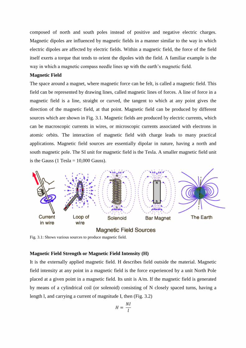
Magnetic Field
The space around a magnet, where magnetic force can be felt, is called a magnetic field. This
field can be represented by drawing lines, called magnetic lines of forces. A line of force in a
magnetic field is a line, straight or curved, the tangent to which at any point gives the
direction of the magnetic field, at that point. Magnetic field can be produced by different
sources which are shown in Fig. 3.1. Magnetic fields are produced by electric currents, which
can be macroscopic currents in wires, or microscopic currents associated with electrons in
atomic orbits. The interaction of magnetic field with charge leads to many practical
applications. Magnetic field sources are essentially dipolar in nature, having a north and
south magnetic pole. The SI unit for magnetic field is the Tesla. A smaller magnetic field unit
is the Gauss (1 Tesla = 10,000 Gauss).
Fig. 3.1: Shows various sources to produce magnetic field.
Magnetic Field Strength or Magnetic Field Intensity (H)
It is the externally applied magnetic field. H describes field outside the material. Magnetic
field intensity at any point in a magnetic field is the force experienced by a unit North Pole
placed at a given point in a magnetic field. Its unit is A/m. If the magnetic field is generated
by means of a cylindrical coil (or solenoid) consisting of N closely spaced turns, having a
length l, and carrying a current of magnitude I, then (Fig. 3.2)

Fig. 3.2: The magnetic field H generated by a cylindrical coil in vacuum and in a medium.
Magnetic induction (or) Magnetic flux density (B)
Magnetic induction or magnetic flux density in any material is the number of magnetic lines
of force passing normally through unit area. The units are w/m2 or Tesla. B represents the
magnitude of the internal field strength within a substance that is subjected to an H field.
Mathematically B can be represented as
Where is the magnetic flux and A is the area of cross section.
Magnetic permeability (μ)
Permeability describes the nature of the material i.e. it is a material property. It is the ease
with which the material allows magnetic lines of force to pass through it or the degree to
which magnetic field can penetrate a given medium is called its permeability. Mathematically
permeability is equal to the ratio of the magnetic induction B inside the material to the
applied magnetic intensity H. Its units are H/m
The value of permeability of free space or μo = 4π x 10-7
H/m.
Relative Permeability (μr)
It is defined as the ratio of permeability of the medium to the permeability of free space i.e.
The magnetic field strength and flux density are related according to
The above equation for vacuum can be written as
Magnetisation
Magnetisation refers to the process of converting a non-magnetic sample into a magnetic
sample. The Intensity of magnetisation (M or I) is defined as the magnetic moment per unit
volume in a material. Its unit is A/m. It is totally depends on the nature of material.
Magnetization of a material is proportional to the magnetic field intensity applied i.e. .
Magnetic susceptibility ( )
Susceptibility describes the nature of the material i.e. it is a material property. It the ease with
which a magnetic material can be magnetised by the magnetising force. The magnetic
susceptibility of a material is the ratio of intensity of magnetisation (M) inside the material to
the magnetising field (H).
Relationship between B, H, M, rand :
Where magnetization M is equal to
i.e.
The first term on the right side of the above equation is due to the external field and the
second term is due to the magnetization.
Thus the magnetic induction (B) in a solid is
The relative permeability,
3.3 ORIGIN OF MAGNETIC MOMENT
The macroscopic magnetic properties of materials are a consequence of magnetic moments
associated with individual electrons. The fundamental reason for the response of a material to

an external magnetic field is that the atoms possess magnetic moments. That is, atom acts like
a tiny magnet. The magnetic properties of solids originate due to the motion of electrons.
There are two types of electron motions: orbital and spin motion. There are three sources that
contribute to atomic magnetic moment:
a) Orbital magnetic moment: Magnetic moment due to the moment of electrons in
orbits around the nucleus, i.e. due to orbital angular momentum.
b) Spin magnetic moment due to electron: Magnetic moment due to spin of the
electrons, i.e. due to spin angular momentum of electron.
c) Spin magnetic moment due to nucleus (Nuclear magnetic moment): Magnetic
moment due to spin of the nucleus, i.e. due to spin angular momentum of nucleus.
The contribution due to spin angular moment of the nucleus i.e. nuclear magnetic moment is
very small (the magnitude of nuclear magnetic moment is 10-3
times that of electronic
magnetic moment) and so their interaction with the external field is masked by the interaction
of the electronic magnetic moment so, it is always neglected.
Orbital Magnetic Moment
In an atom electrons revolve round the nucleus in different orbits these revolving electrons
constitute an electric current in the orbits this is equivalent to current in a closed circuit (fig.
1.3). Suppose an electron is revolving around a nucleus. Let the charge on the electron be ‘e’
and the radius of its orbit be ‘r’. The revolving electron is like a loop of current. The direction
of current in this loop is opposite to the direction of the revolution of the electron. Thus, if the
electron revolves in the clockwise direction, it constitutes an anticlockwise current, and vice
versa. The orbital magnetic moment is given by the equation
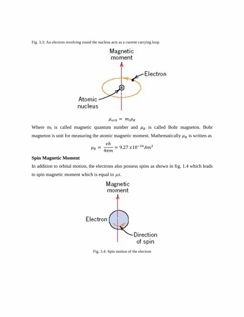
Fig. 3.3: An electron revolving round the nucleus acts as a current carrying loop
Where ml is called magnetic quantum number and is called Bohr magneton. Bohr
magneton is unit for measuring the atomic magnetic moment. Mathematically is written as
Spin Magnetic Moment
In addition to orbital motion, the electrons also possess spins as shown in fig. 1.4 which leads
to spin magnetic moment which is equal to
Fig. 3.4: Spin motion of the electron
3.4 CLASSIFICATION OF MAGNETIC MATERIALS
Now we are going to study the various properties of magnetic materials in terms of the
magnetic properties of the atomic dipoles and the interaction between them.
The first distinction is based on whether the atoms carry permanent magnetic dipoles or not.
Materials which lack permanent dipoles are called diamagnetic. If the atoms of the materials
carry permanent magnetic dipoles such a material may be paramagnetic, ferromagnetic, anti
ferromagnetic, and ferrimagnetic depending on the interaction between the individual dipoles.
If the permanent dipoles do not interact among themselves the material is called
paramagnetic. If the interaction among permanent dipoles is strong such that all dipoles line
up in parallel, the material is ferromagnetic. If permanent dipoles line up in anti parallel
direction, then the material can be anti ferromagnetic or ferrimagnetic. In anti ferromagnetic
material the magnitudes of permanent dipoles aligned parallel and anti parallel are equal and
hence the magnetisation vanishes. In case of ferrimagnetic materials, magnitudes of
permanent dipoles aligned anti parallel are not equal thus exhibiting magnetization.
Diamagnetic Materials
Diamagnetism is a fundamental property of all matter. Diamagnetismis a very weak form of
magnetism. Diamagnetism persists only in presence of an external magnetic field. It is
induced by a change in the orbital motion of electrons due to an applied magnetic field.
Diamagnetic material does not possess permanent dipoles. Dipoles are induced only in
presence of external magnetic field as shown in fig 2.6. The magnitude of the induced
magnetic moment is extremely small, and in a direction opposite to that of the applied field
and hence tends to decrease the magnetic induction present in the material (fig 2.5). Thus
diamagnetism is the phenomenon by which the induced magnetic moment is always in the
opposite direction of the applied field. Thus, the relative permeability is less than unity
(however, only very slightly), and the magnetic susceptibility is negative; that is, the
magnitude of the Bfield within a diamagnetic solid is less than that in a vacuum. The volume
susceptibility for diamagnetic solid materials is on the order of -10-5
. When placed between
the poles of a strong electromagnet, diamagnetic materials are attracted toward regions where
the field is weak. Though diamagnetism is present in all materials but it is masked by other
types of magnetism because it is very weak. It can be observed only when other types of
magnetism are absent.
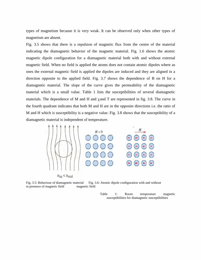
Fig. 3.5 shows that there is a repulsion of magnetic flux from the centre of the material
indicating the diamagnetic behavior of the magnetic material. Fig. 1.6 shows the atomic
magnetic dipole configuration for a diamagnetic material both with and without external
magnetic field. When no field is applied the atoms does not contain atomic dipoles where as
ones the external magnetic field is applied the dipoles are induced and they are aligned in a
direction opposite to the applied field. Fig. 3.7 shows the dependence of B on H for a
diamagnetic material. The slope of the curve gives the permeability of the diamagnetic
material which is a small value. Table 1 lists the susceptibilities of several diamagnetic
materials. The dependence of M and H and and T are represented in fig. 3.8. The curve in
the fourth quadrant indicates that both M and H are in the opposite directions i.e. the ratio of
M and H which is susceptibility is a negative value. Fig. 3.8 shows that the susceptibility of a
diamagnetic material is independent of temperature.
Fig. 3.5: Behaviour of diamagnetic material Fig. 3.6: Atomic dipole configuration with and without
in presence of magnetic field magnetic field
Table 1: Room temperature magnetic
susceptibilities for diamagnetic susceptibilities

Fig. 3.7: B Versus H for diamagnetic and
paramagnetic materials
Examples of diamagnetic materials: Bismuth (Bi), Zinc (Zn), copper (Cu), Silver (Ag), Gold
(Au), Salt (NaCl), Water (H2O), Mercury (Hg), Hydrogen (H2), Ge, Si.
Fig. 3.8: Curves showing M Vs H and χ Vs T for diamagnetic materials
Properties of diamagnetic materials
1. An atom of this material does not contain permanent dipoles.
2. An atom of this material has no magnetic dipole moment.
3. The effect is weak and often masked by other kinds of magnetism.
4. A Dia-magnet is weakly repelled by a normal magnet.
5. Relative permeability is less than 1 but only slightly less than unity.
6. Magnetic susceptibility is negative but only slightly less than unity.
7. Magnetic susceptibility is independent of temperature.

8. Magnetic susceptibility is independent of applied magnetic field strength.
9. Atomic orbitals are completely filled. (no electron is un-paired).
Paramagnetic Materials
A paramagnetic material contains permanent dipoles which are because of incomplete
cancellation of electron spin and orbital magnetic moments which results in a resultant
magnetic moment even in the absence of applied field. In the absence of external magnetic
field the dipoles are randomly oriented resulting in zero net magnetic moment. When external
magnetic field is applied, some of the permanent dipoles try to align in the direction of the
magnetic field (fig. 3.9). Since few dipoles try to align in the direction of the magnetic field
the net magnetic moment produced in the material is small so the material is feebly
magnetised. When placed inside the magnetic field the material allows magnetic lines of force
to pass through it as shown in Fig. 3.10. There is no interaction between the adjacent dipoles
they are acted upon individually. The relative permeability is greater than unity. Magnetic
susceptibility is positive but relatively small value. The susceptibilities of paramagnetic
values range from 10-5
to 102. These materials are used in lasers and masers. Where one can
create the required energy levels of transition. Paramagnetic property of oxygen is used in the
NMR imaging instrument which is used to diagnose the brain tumour or blood clot in t he
brain.
Fig. 3.9 Atomic dipole configuration with and without Fig. 3.10: Behaviour of paramagnetic
external magnetic field for a paramagnetic material material in external magnetic field.

Table 2: Room temperature magnetic susceptibility
for paramagnetic material
Fig. 3.11: Curves showing M Vs H and χ Vs T for
paramagnetic materials
As H increases M also increases in the same fashion which results in a straight line passing
through origin. The slope of the curve gives susceptibility which is positive and relatively
small value. The curve shows that the susceptibility of paramagnetic material is dependent of
temperature. With increase in temperature the susceptibility of the paramagnetic material
decreases.
Properties of paramagnetic materials
1. They attract magnetic lines of force when placed in magnetic field.
2. In the absence of external magnetic field the dipoles are randomly oriented.
3. An atom of this material possesses a non-zero magnetic dipole moment.
4. Possess permanent dipole moment.
5. Relative permeability is slightly greater than unity.
6. Magnetic susceptibility is positive and small.
7. Magnetic susceptibility is independent of applied magnetic field strength but depend
on temperature.
8. With increase in temperature the susceptibility of the material decreases.
9. Examples: Aluminium, Platinum, Manganese, Copper Chloride, Oxygen, solutions of
salts of iron.

Ferromagnetic Materials
Certain metallic materials possess a permanent magnetic moment even in the absence of
external magnetic field which results in very large and permanent magnetisation. Permanent
magnetic moment in ferromagnetic materials is due to uncancelled spins of the electron, there
is some amount of orbital magnetic moment but its value is small when compared with spin
magnetic moment. In a ferromagnetic material the dipoles of the adjacent atoms interact with
each other which results in parallel alignment of all the dipoles (Fig. 3.12). This interaction
between the adjacent atoms is called exchange interaction or exchange coupling. Due to the
parallel alignment if we apply a small value of magnetic field to a ferromagnetic material a
large value of magnetisation is produced. Due to the parallel alignment of the atomic dipoles
the material possesses a characteristic feature called spontaneous magnetisation. In presence
of magnetic field the material allows more number of lines to pass through it as shown in fig.
3.13. In presence of external magnetic field all the atomic dipoles are aligned in the direction
of external magnetic field which results in a characteristic feature called saturation
magnetisation (Ms) there is also corresponding saturation flux density (Bs). The saturation
magnetisation is equal to the product of the net magnetic moment for each atom and the
number of atoms present. For each of iron, cobalt and nickel, the net magnetic moments per
atom are 2.22, 1.72 and 0.60 Bohr magnetons respectively. Ferromagnetic materials possess a
characteristic feature called Hysteresis.
The susceptibility of a ferromagnetic material is temperature dependent. A ferromagnetic
material exhibits two different properties. Below a particular temperature called Curie
temperature it behaves as a ferromagnetic and above that Curie temperature it behaves as a
paramagnetic material (Fig. 3.14). The relative permeability is very large. Magnetic
susceptibility is as high as 106. Thus H<<<M such that B can be written as
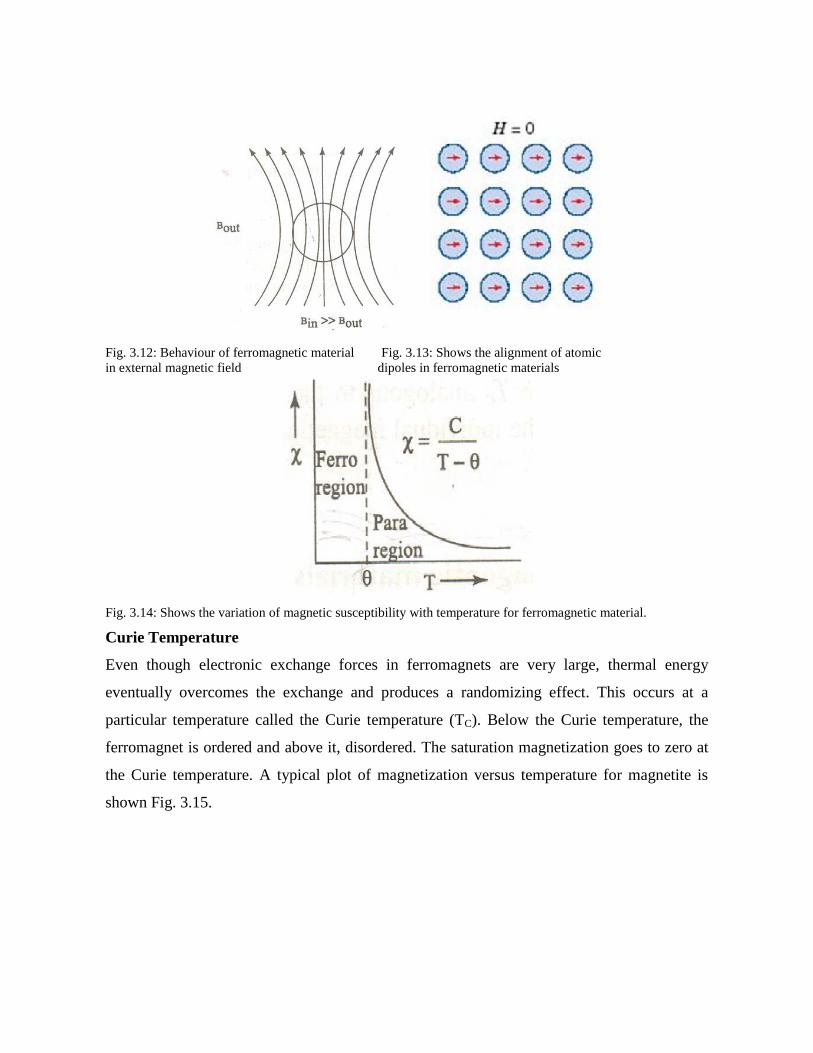
Fig. 3.12: Behaviour of ferromagnetic material Fig. 3.13: Shows the alignment of atomic
in external magnetic field dipoles in ferromagnetic materials
Fig. 3.14: Shows the variation of magnetic susceptibility with temperature for ferromagnetic material.
Curie Temperature
Even though electronic exchange forces in ferromagnets are very large, thermal energy
eventually overcomes the exchange and produces a randomizing effect. This occurs at a
particular temperature called the Curie temperature (TC). Below the Curie temperature, the
ferromagnet is ordered and above it, disordered. The saturation magnetization goes to zero at
the Curie temperature. A typical plot of magnetization versus temperature for magnetite is
shown Fig. 3.15.
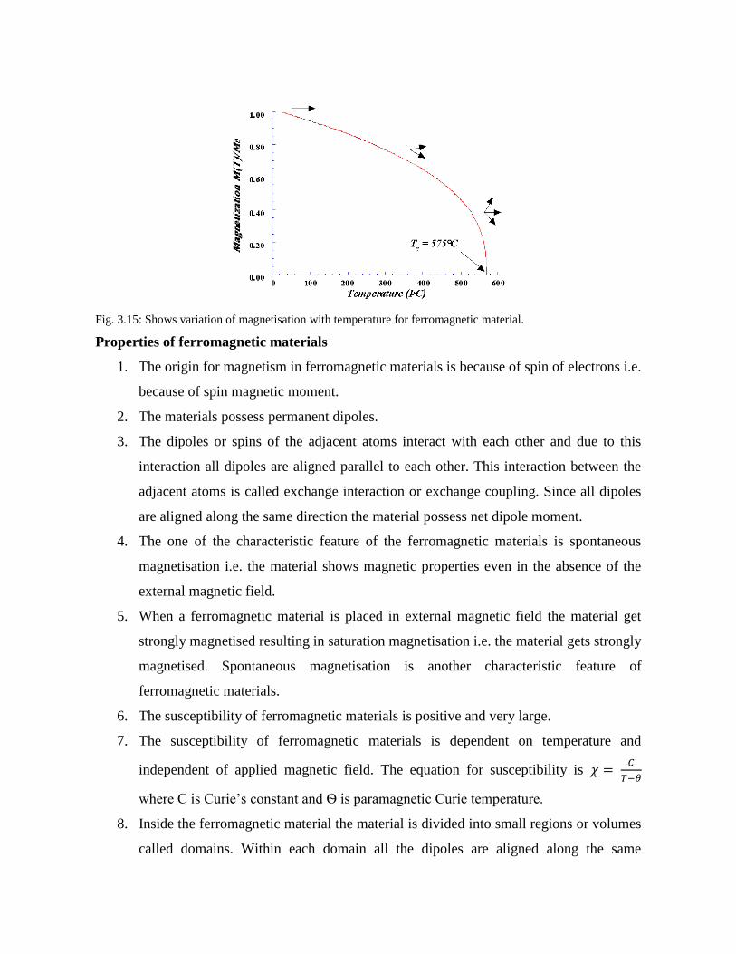
Fig. 3.15: Shows variation of magnetisation with temperature for ferromagnetic material.
Properties of ferromagnetic materials
1. The origin for magnetism in ferromagnetic materials is because of spin of electrons i.e.
because of spin magnetic moment.
2. The materials possess permanent dipoles.
3. The dipoles or spins of the adjacent atoms interact with each other and due to this
interaction all dipoles are aligned parallel to each other. This interaction between the
adjacent atoms is called exchange interaction or exchange coupling. Since all dipoles
are aligned along the same direction the material possess net dipole moment.
4. The one of the characteristic feature of the ferromagnetic materials is spontaneous
magnetisation i.e. the material shows magnetic properties even in the absence of the
external magnetic field.
5. When a ferromagnetic material is placed in external magnetic field the material get
strongly magnetised resulting in saturation magnetisation i.e. the material gets strongly
magnetised. Spontaneous magnetisation is another characteristic feature of
ferromagnetic materials.
6. The susceptibility of ferromagnetic materials is positive and very large.
7. The susceptibility of ferromagnetic materials is dependent on temperature and
independent of applied magnetic field. The equation for susceptibility is
where C is Curie’s constant and Ѳ is paramagnetic Curie temperature.
8. Inside the ferromagnetic material the material is divided into small regions or volumes
called domains. Within each domain all the dipoles are aligned along the same
direction resulting in spontaneous magnetisation. All these domains are randomly
oriented thus resulting in zero net dipole moment.
9. In ferromagnetic materials the flux density (B) or magnetisation (M) is not directly
proportional to applied magnetic field (H), i.e. the ferromagnetic material possess
magnetisation for sometime even when magnetizing field is removed thus exhibiting
the property of hysteresis. This is a characteristic feature of ferromagnetic materials.
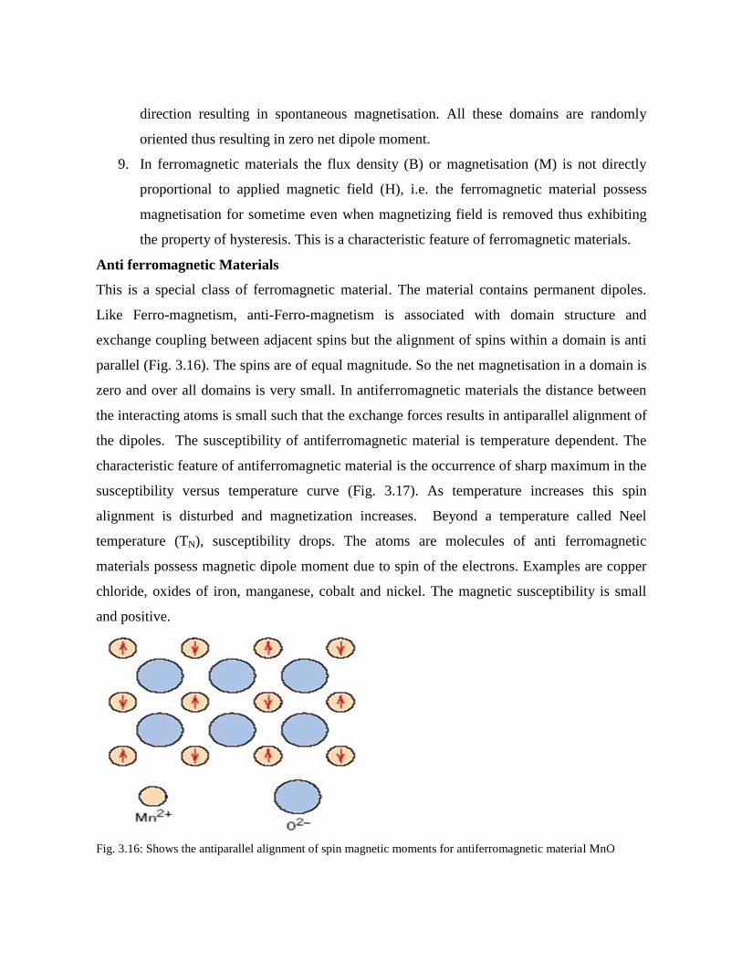
Anti ferromagnetic Materials
This is a special class of ferromagnetic material. The material contains permanent dipoles.
Like Ferro-magnetism, anti-Ferro-magnetism is associated with domain structure and
exchange coupling between adjacent spins but the alignment of spins within a domain is anti
parallel (Fig. 3.16). The spins are of equal magnitude. So the net magnetisation in a domain is
zero and over all domains is very small. In antiferromagnetic materials the distance between
the interacting atoms is small such that the exchange forces results in antiparallel alignment of
the dipoles. The susceptibility of antiferromagnetic material is temperature dependent. The
characteristic feature of antiferromagnetic material is the occurrence of sharp maximum in the
susceptibility versus temperature curve (Fig. 3.17). As temperature increases this spin
alignment is disturbed and magnetization increases. Beyond a temperature called Neel
temperature (TN), susceptibility drops. The atoms are molecules of anti ferromagnetic
materials possess magnetic dipole moment due to spin of the electrons. Examples are copper
chloride, oxides of iron, manganese, cobalt and nickel. The magnetic susceptibility is small
and positive.
Fig. 3.16: Shows the antiparallel alignment of spin magnetic moments for antiferromagnetic material MnO
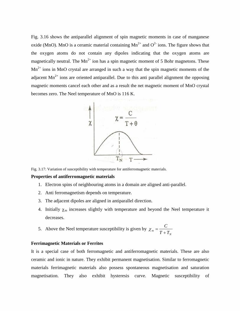
Fig. 3.16 shows the antiparallel alignment of spin magnetic moments in case of manganese
oxide (MnO). MnO is a ceramic material containing Mn2+
and O2-
ions. The figure shows that
the oxygen atoms do not contain any dipoles indicating that the oxygen atoms are
magnetically neutral. The Mn2+
ion has a spin magnetic moment of 5 Bohr magnetons. These
Mn2+
ions in MnO crystal are arranged in such a way that the spin magnetic moments of the
adjacent Mn2+
ions are oriented antiparallel. Due to this anti parallel alignment the opposing
magnetic moments cancel each other and as a result the net magnetic moment of MnO crystal
becomes zero. The Neel temperature of MnO is 116 K.
Fig. 3.17: Variation of susceptibility with temperature for antiferromagnetic materials.
Properties of antiferromagnetic materials
1. Electron spins of neighbouring atoms in a domain are aligned anti-parallel.
2. Anti ferromagnetism depends on temperature.
3. The adjacent dipoles are aligned in antiparallel direction.
4. Initially m increases slightly with temperature and beyond the Neel temperature it
decreases.
5. Above the Neel temperature susceptibility is given by N
mTT
C
Ferrimagnetic Materials or Ferrites
It is a special case of both ferromagnetic and antiferromagnetic materials. These are also
ceramic and ionic in nature. They exhibit permanent magnetisation. Similar to ferromagnetic
materials ferrimagnetic materials also possess spontaneous magnetisation and saturation
magnetisation. They also exhibit hysteresis curve. Magnetic susceptibility of
ferrimagneticmaterials is very large and positive. The magnetic susceptibility is temperature
dependent. Fig. 3.18 shows the variation of susceptibility with temperature for ferrimagnetic
materials. Ferrimagnetic materials are composed of two sets of different transition metal ions
having different values of magnetic moments with antiparallel alignment. Saturation
magnetisation of ferrimagnetic materials is not as high as ferromagnetic materials. Since they
are ceramic in nature they are suitable for high frequency applications and in special magnetic
devices.
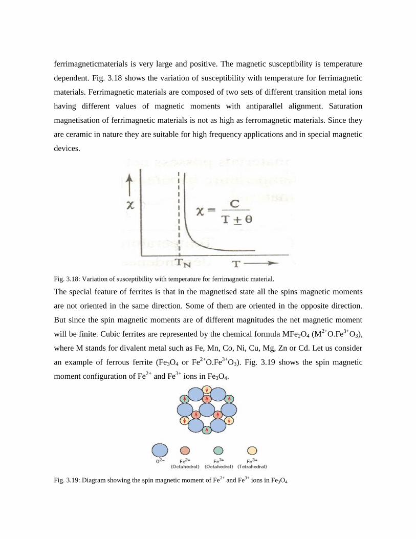
Fig. 3.18: Variation of susceptibility with temperature for ferrimagnetic material.
The special feature of ferrites is that in the magnetised state all the spins magnetic moments
are not oriented in the same direction. Some of them are oriented in the opposite direction.
But since the spin magnetic moments are of different magnitudes the net magnetic moment
will be finite. Cubic ferrites are represented by the chemical formula MFe2O4 (M2+
O.Fe3+
O3),
where M stands for divalent metal such as Fe, Mn, Co, Ni, Cu, Mg, Zn or Cd. Let us consider
an example of ferrous ferrite (Fe3O4 or Fe2+
O.Fe3+
O3). Fig. 3.19 shows the spin magnetic
moment configuration of Fe2+
and Fe3+
ions in Fe3O4.
Fig. 3.19: Diagram showing the spin magnetic moment of Fe2+
and Fe3+
ions in Fe3O4

The cubic cell contains 8 molecules per unit cell. There are 32 O2-
ions, 16 Fe3+
and 8 Fe2+
ions, per unit cell. The oxygen atoms are magnetically neutral. 8 Fe3+
ions and 8 Fe2+
ions
occupy the octahedral sites, i.e. each ion is surrounded by 6 oxygen ions. The spins of all
these ions are oriented parallel to each other. The other 8 Fe3+
ions, occupy tetrahedral sites
i.e. each ion is surrounded by 4 oxygen ions. The spins of these 8 ions in the tetrahedral sites
are all oriented antiparallel with the spins in the octahedral sites. This is illustrated in table 3.
Table 3: The distribution of spin magnetic moments for Fe2+
and Fe3+
ions in a unit cell Fe3O4
The net spin magnetic moment of Fe3+
ions is zero as the 8 spins in the octahedral sites cancel
the 8 antiparallel spins in the tetrahedral sites. The spin magnetic moment of the 8 Fe2+
ions
contribute to the magnetisation per unit cell. This accounts for the spontaneous magnetisation
of ferrites.
Ceramic materials other than cubic ferrites are also ferrimagnetic materials they are hexagonal
ferrites with chemical formula AB12O19 in which A is a divalent metal such as barium, lead or
strontium and B is a trivalent metal ion such as aluminium, gallium, chromium or iron and
garnets with chemical formula M3Fe5O12 where M represents rare earth metal ion such as
samarium, europium, gadolinium or yttrium.
Properties of ferrimagnetic materials
1. Ferrimagnetic materials possess net magnetic moment.
2. Above Curie temperature it becomes paramagnetic.
3. Magnetic susceptibility is very large.

4. Spin alignment is anti parallel of different magnitudes.
5. They have the characteristic property like spontaneous magnetisation and saturation
magnetisation.
6. Ferromagnetic materials behave like Ferromagnetic materials and have hysteresis,
domain structure etc., but being oxide compounds they have large resistivities.
7. They are also called ferrites.
8. Above the Curie temp susceptibility is given by C
mTT
C
Table 4: Differences between various magnetic materials.
Type of
Magnetism Susceptibility Atomic / Magnetic Behavior
Example /
Susceptibility
Diamagnetism Small &
negative.
Atoms
have no
magnetic
moment
Au
Cu
-2.74x10-
6
-0.77x10-
6
Paramagnetism Small &
positive.
Atoms
have
randomly
oriented
magnetic
moments
β-Sn
Pt
Mn
0.19x10⁻⁶
21.04x10-
6
66.10x10-
6
Ferromagnetism
Large &
positive,
function of
applied field,
microstructure
dependent.
Atoms
have
parallel
aligned
magnetic
moments
Fe ~100,000

Antiferromagnetism Small &
positive.
Atoms
have
mixed
parallel
and anti-
parallel
aligned
magnetic
moments
Cr 3.6x10⁻⁶
Ferrimagnetism
Large &
positive,
function of
applied field,
microstructure
dependent
Atoms
have
anti-
parallel
aligned
magnetic
moments
Ba
ferrite ~3
3.5 DOMAIN THEORY OF FERROMAGNETIC MATERIALS
In 1907, Weiss proposed domain theory to explain ferromagnetic behaviour of a
ferromagnetic material. According to him a single crystal of ferromagnetic solid compresses a
large number of small regions, each region is spontaneously magnetised to saturation extent
called a domain as shown in fig. 1.20.
Fig. 3.20: Domain structure of ferromagnetic material.
The separation between the adjacent domains is called domain wall. Each domain is
spontaneously magnetised and all the domains are randomly oriented such that the net

magnetic moment of the crystal is zero. When such a material is placed in the magnetic field
the material get magnetised by two processes
1. Domain wall movement: The domains which are favourably oriented in the direction
of the magnetising field increase in volume at the cost of those that are unfavourably
oriented.
2. Rotation of the domains: Application of higher magnetic fields rotates partially the
domains in the direction of the magnetising field. This results in further increase in the
magnetising field.
In the process of domain growth 4 types of energies are involved.
Exchange energy
The interaction energy makes the adjacent dipoles align themselves. It arises from interaction
of electron spins. It depends upon the interatomic distance. This exchange energy also called
magnetic field energy. It is the energy required in assembling the atomic magnets into a single
domain and this workdone is stored as potential energy.
Anisotropy energy
In ferromagnetic crystals, energy of magnetization is found to be a function of crystal
orientation. i.e., crystals have easy and hard directions of magnetization. The excess energy
required to magnetize it along easy way of direction is called anisotropy energy.
Eg. In bcc iron crystal easy direction of magnetization is [1,0,0], medium way of
magnetization is [1,1,0] and hard way of magnetization direction is [1,1,1].
Domain wall or Bloch wall energy
A thin region that separates adjacent domains magnetized in different directions is called
domain wall or Bloch wall. It is sum of contributions from exchange an crystalline anisotropy
energies in the domain wall regions.
Magnetostriction energy
The change in the dimensions of a ferromagnetic material when it is magnetized is known as
magnetostriction. The deformation is different along different crystal directions but it is
independent of the direction of field. Depending on the nature of the material the dimension
may either increase or decrease.
Eg. For a nickel rod length decreases, for permalloy the length increases in the presence of
magnetic fields.
Reversible and Irreversible domains
If apply a small external field on the ferromagnetic material the domain wall is displaced
slightly away from the minimum energy. But it returns to the original position when the field
is removed. This gives a reversible domain.
In large external fields, the domain wall may be shifted to a more distant position where the
energy curve has passed through a maximum and diminished. On removing the field, the
domain wall cannot cross the energy maximum and so it is unable to return to its initial
position. This gives irreversible domain.
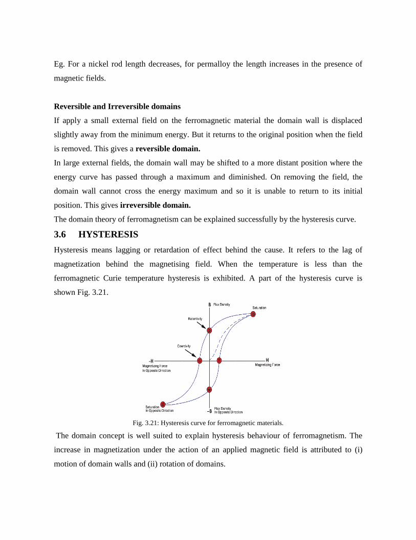
The domain theory of ferromagnetism can be explained successfully by the hysteresis curve.
3.6 HYSTERESIS
Hysteresis means lagging or retardation of effect behind the cause. It refers to the lag of
magnetization behind the magnetising field. When the temperature is less than the
ferromagnetic Curie temperature hysteresis is exhibited. A part of the hysteresis curve is
shown Fig. 3.21.
Fig. 3.21: Hysteresis curve for ferromagnetic materials.
The domain concept is well suited to explain hysteresis behaviour of ferromagnetism. The
increase in magnetization under the action of an applied magnetic field is attributed to (i)
motion of domain walls and (ii) rotation of domains.

When a magnetic field is applied, for small fields, domains that are favourably oriented to the
field and in the easy direction of magnetization grow in size at the expense of less favourably
oriented domains (Fig. 3.22). This results in Block wall movement and when the weak field
is removed the domains revert back to their original state. This reversible wall movement is
indicated by OA in the plot given above. In region ‘A’ the growth of magnetization is slow.
When the field becomes stronger Block wall movement continues but it is mostly irreversible
movement. AB is this region in the plot.
Fig. 3.22: Domain configurations during several stages of magnetisation are represented.
At the point B all domains have got magnetized along their easy directions. A still larger
magnetic field rotates the domains into the field direction, which may be away from the easy
direction thereby storing anisotropy energy. Once the domain rotation is complete the
magnetization reaches to a saturation value (point C on the plot)
On removal of the external field the specimen tends to attain the original configuration by
movement of Block walls. But this movement is hampered by impurities and lattice
imperfections and so some energy is wasted trying to overcome opposition. Further domain
wall movement is irreversible. When the field becomes zero, magnetization has not vanished.
There is a remanent magnetization ‘Br’ at H=0.
This means that a coercive field ‘–Hc‘ has to be applied to demagnetize the specimen. The
amount of energy spent in a hysteresis cycle is energy lost (heat). The area of hysteresis loop
represents energy lost during magnetisation and demagnetisation of the material. This energy
lost is manifested as heat that is generated within the magnetic specimen and is capable of
raising its temperature. The area of the hysteresis loop also classifies soft and hard magnets.

3.7 SOFT AND HARD MAGNETIC MATERIALS
Soft Magnetic Materials
Both ferromagnetic and ferrimagnetic materials are classified as either soft or hard on the
basis of their hysteresis characteristics.
Soft magnetic materials are used in applications requiring frequent reversals of the directions
of magnetization such as cores of transformers, motors, inductors and generators. In soft
magnetic materials the hysteresis losses must be small. More over the soft magnetic materials
are characterised by low remanentmagnetisation, low coercivity, low hysteresis losses, high
magnetic permeability, high initial permeability and high susceptibility so that they can be
easily magnetised and demagnetised. A material possessing these properties can reach its
saturation magnetization with low applied field. Consequently the area is small and hysteresis
loss also reduced. The hysteresis curve is shown in Fig. 3.23.
A low value of coercivity corresponds to the easy movement of domain walls as the magnetic
field changes in magnitude or direction. Structural defects such as imperfections,
irregularities, inclusions, impurities and voids in the magnetic material tend to restrict the
motion of domain walls and thus increase the coercivity. Consequently, a soft magnetic
material must be free of such structural defects.
There is another energy loss in soft magnetic materials i.e. eddy current loss. When the
magnetic flux in a medium is changing, an emf is induced. According to Lenz’s law, the
induced emf is proportional to the frequency of the alternating current. The induced emf sets
up eddy currents in the medium and the power loss due to these eddy currents is equal to
V2/R. Where V is the induced emf and R is the resistance of the medium. Eddy current losses
can be minimized by increasing the resistivity of the magnetic medium. This is accomplished
in ferromagnetic materials: iron-silicon alloys and iron-nickel alloys. The ceramic ferrites are
commonly used for applications requiring soft magnetic materials because they are naturally
electrical insulators.
The eddy currents produce a magnetic field of their own which opposes the main magnetic
field. As the effect of eddy currents is not uniform over the cross section of the material, these

results in a flux distribution which is not uniform, the flux density in the outer portions being
greater than that at the centre. Thus there is a reduction in effective cross section.
So, the magnetic materials used for varying magnetic fields are laminated ( made up of thin
sheets insulated from each other) so as to reduce eddy currents and associated losses, due to
lamination the area of path of eddy currents is reduced giving rise to a large value of
resistance. Eddy current losses are reduced by using thinner plates and a material of higher
resistivity.
Fig. 3.23: Magnetisation curves for soft and hard magnetic materials.
Hard Magnetic Materials
Hard magnetic materials are used in permanent magnets, which must have a high resistance to
demagnetization. A hard magnetic material is characterised by a high remanence, high
coercivity, high saturation flux density as well as a low initial permeability and high
hysteresis energy losses. The hysteresis curve for hard magnetic material is as shown in Fig.
3.23.
The two most important characteristics relative to applications for these materials are the
coercivity and energy product (BH)max. The value of the energy product represents the amount
of energy required to demagnetize a permanent magnet. If (BH)max is large, that material will
be hard in terms of its magnetic characteristics as shown in Fig. 3.24.
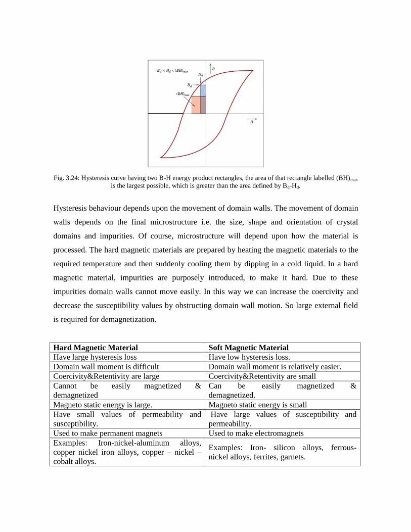
Fig. 3.24: Hysteresis curve having two B-H energy product rectangles, the area of that rectangle labelled (BH)max
is the largest possible, which is greater than the area defined by Bd-Hd.
Hysteresis behaviour depends upon the movement of domain walls. The movement of domain
walls depends on the final microstructure i.e. the size, shape and orientation of crystal
domains and impurities. Of course, microstructure will depend upon how the material is
processed. The hard magnetic materials are prepared by heating the magnetic materials to the
required temperature and then suddenly cooling them by dipping in a cold liquid. In a hard
magnetic material, impurities are purposely introduced, to make it hard. Due to these
impurities domain walls cannot move easily. In this way we can increase the coercivity and
decrease the susceptibility values by obstructing domain wall motion. So large external field
is required for demagnetization.
Hard Magnetic Material Soft Magnetic Material
Have large hysteresis loss Have low hysteresis loss.
Domain wall moment is difficult Domain wall moment is relatively easier.
Coercivity&Retentivity are large Coercivity&Retentivity are small
Cannot be easily magnetized &
demagnetized
Can be easily magnetized &
demagnetized.
Magneto static energy is large. Magneto static energy is small
Have small values of permeability and
susceptibility.
Have large values of susceptibility and
permeability.
Used to make permanent magnets Used to make electromagnets
Examples: Iron-nickel-aluminum alloys,
copper nickel iron alloys, copper – nickel –
cobalt alloys.
Examples: Iron- silicon alloys, ferrous-
nickel alloys, ferrites, garnets.
3.8 FERRITE APPLICATIONS
1. Being Ferro-magnetic but with high resistivity helps ferrites to cut down on eddy
currents in transformer cores up to microwave frequencies.
2. They are used as induction cores, antennas for medium and long wave broad casting,
electronic tuning, auto frequency control, fm, switching etc.
3. Since ferrites have a hysteresis loop they are used as memory elements for rapid
storage and retrieval of digital information by switching the direction of magnetization
in very small toroidal cores.
4. Garnets (Y3Fe5O12) are useful in microwave applications.
5. Ferrite domains are also useful for memory.
6. Magnetic recording uses ferrite material in powder form.
7. Ferrites can be used as magnets.
3.9 MAGNETIC STORAGE
These days scientists are try to find new type of storage devises to store a large amount of
information. By the past few years magnetic materials has evolved as a better solution for
storage of large amount of data. Magnetic recording has become the only method for the
storage of information like audio tapes, VCRs, disk storage media, credit cards and so on.
Recording process
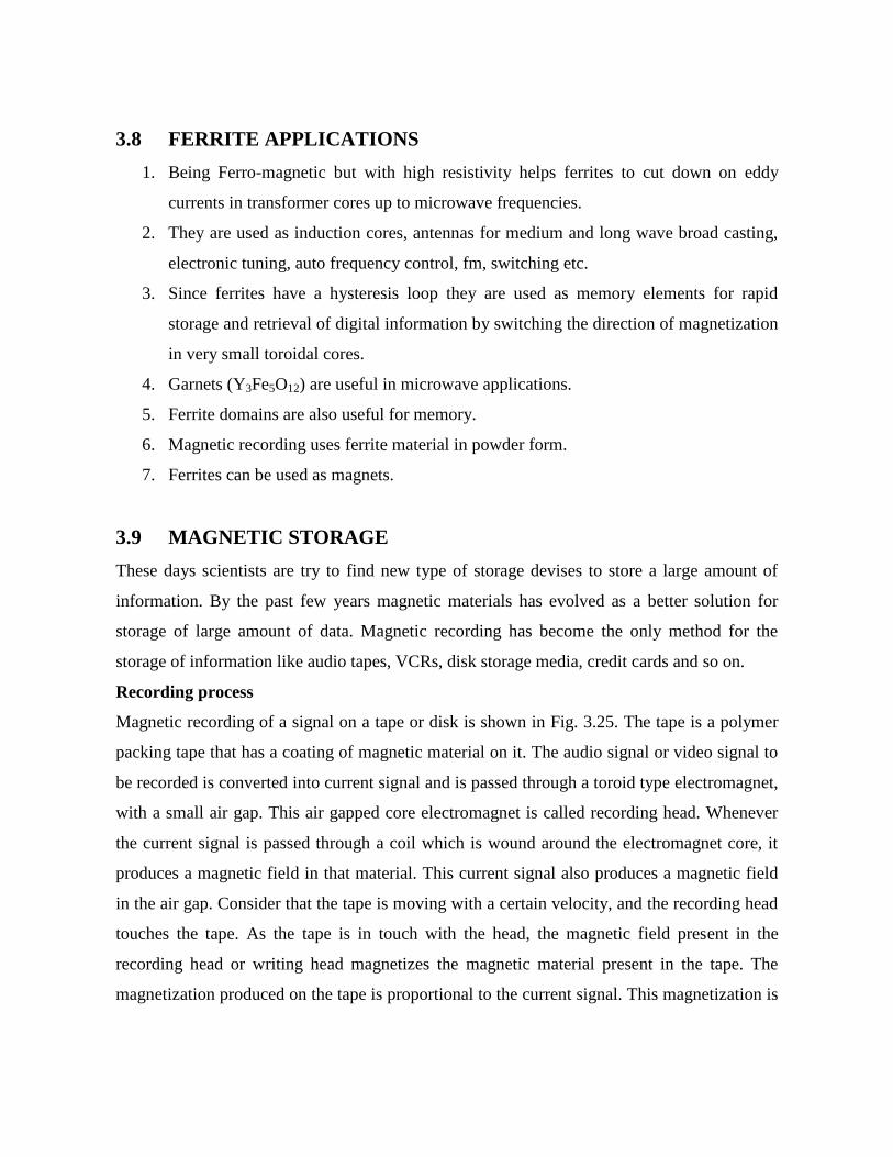
Magnetic recording of a signal on a tape or disk is shown in Fig. 3.25. The tape is a polymer
packing tape that has a coating of magnetic material on it. The audio signal or video signal to
be recorded is converted into current signal and is passed through a toroid type electromagnet,
with a small air gap. This air gapped core electromagnet is called recording head. Whenever
the current signal is passed through a coil which is wound around the electromagnet core, it
produces a magnetic field in that material. This current signal also produces a magnetic field
in the air gap. Consider that the tape is moving with a certain velocity, and the recording head
touches the tape. As the tape is in touch with the head, the magnetic field present in the
recording head or writing head magnetizes the magnetic material present in the tape. The
magnetization produced on the tape is proportional to the current signal. This magnetization is
retained in the material when field is removed or current signal is off. Thus the signal gets
stored in the tape.
Actually the data to be stored or recorded is in the form of time sequence of binary digits (one
and zero) or bits. These bits are converted into an electric current wave form that passes
through a coil of writing head as shown in Fig. 3.25. A ‘one’ bit corresponds to a change in
current polarity, while a zero bit corresponds to no change in polarity of the writing current
signal. Thus a moving disk or tape is magnetized in the positive direction for positive current
and in the negative direction for negative direction for negative current flow.
Fig. 3.25: The process of reading and writing the information digitally onto the storage medium.
Reading process
The recording head used for recording on tape is also used for reading (or playing audio
cassette) the tape. The reading process in a tape is based on the principle of Faraday’s law of
induction (Fig. 3.26). A portion of the magnetic field present in the tape penetrates through
the recording head when the tape is in touch with the head. As the tape is moving with a

constant velocity, voltage is induced due to change in magnetic field. This can be amplified
and then converted back into its original form.
The complete process of writing and reading the information can be better understood from
the Fig. 3.27.
Storage of Magnetic Data (Tapes, Floppy and Magnetic Disc Drives)
Magnetic data can be stored in devices like tapes, floppy and hard disk. The magnetic
materials used for storage should retain the information recorded in them when magnetic field
is removed. This requires high remanentmagnetisation and optimum value of coercivity.
Fig. 3.26: Representation of how data is stored and retrieved using a magnetic storage medium.

Fig. 3.27: The process of reading and writing of information on the recording media.
The coercivity determines the stability of recording. The coercivity cannot be too high, since
it can stop the reading. Regarding magnetic properties, the hysteresis loops for these magnetic
storage media should be relatively large and square.
There are two types of magnetic storage media. Those are particulate and thin film.
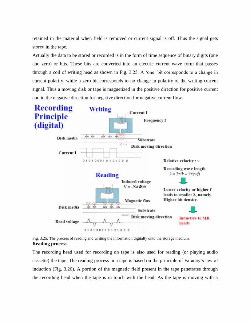
Particulate media consist of very small needle like or acicular particles. Ex: γ-Fe2O3 ferrite,
Co- γ- Fe2O3 ferrite and CrO2. During manufacture these particles are aligned with their long
axes in a direction that parallels the direction of motion of tape. In this each particle acts as a
single domain that can be magnetised only with its magnetic moment lying along the axis.
There are two magnetic states are possible, corresponding to saturation magnetisation along
the axial direction and its opposite. Since there are two states available information can be
stored digitally as 0’s and 1’s. Fig. 3.28 shows γ-Fe2O3 material. Table 5 lists the various
types of particulate media.
Fig. 3.28: A scanning electron micrograph showing microstructure of needle shaped particles of γ-Fe2O3
Table 5: Summary of the characteristics of various particulate media.
The thin film storage technology is the new technology. It provides higher storage capacities
at lower costs. It is employed in hard disk drives. It consists of a multi layered structure. Ex:
Co-Pt-Cr alloy, Co-Cr-Ta alloy (thickness 10 to 50 nm). The thin film is a poly crystalline
material. Each grain within the thin film is a single magnetic domain as shown in fig 2.29.
The grain shape and size must be uniform. The crystallographic direction of easy
magnetization for each grain is aligned in the direction of disk motion (or the direction of
opposite). Table 6 lists the various types of thin film materials. The mechanism of magnetic
storage in these two methods is same i.e. the two magnetic states correspond to domain
magnetization in one direction or its antiparallel direction.
The storage density of thin films is greater than media. Because the packing efficiency of thin
film domains is greater than acicular particles. There is void space in between particles. Bs
values for particulate media lie in between 0.4 and 0.6Tesla. For thin films Bs values lie in
between 0.6 and 1.2Tesla.

Fig. 3.29: A high resolution transmission electron micrograph showing microstructure of Co-Cr-Pt and grain
structure representation
Table 6: Comparison of properties of various Thin-Films compositions for media
3.10 TRANSFORMER
The material to be used as a transformer core should have the following properties
1. It should be ceramic in nature in order to minimize the eddy current losses.
2. The material should have very high permeability such that it can be easily magnetised
and demagnetised.
3. The material should have very high susceptibility.
4. The material should have no coresive field and low remeanent field.
5. The phenomenon of magnetostriction should be small.
For transformer cores we use soft magnetic materials which are easily magnetized and
demagnetized. Ex: Iron-Silicon alloy (97% Fe & 3% Si). In iron-silicon alloy, silicon
increases the permeability, decreases hysteresis loss and eddy current loss, its presence
increases the electrical resistivity. It is useful to the magnetic property, but decreases the
ductility.
Single crystals of this alloy are magnetically anisotropic. But single crystals are very
expensive to prepare. So, for transformer cores, poly crystalline sheets of Fe-Si alloy, which
are anisotropic, are fabricated. Actually the grains in polycrystalline materials are randomly
oriented; due to this their properties are isotropic. But we can develop anisotropy in poly
crystalline materials via plastic deformation, for example by rolling.
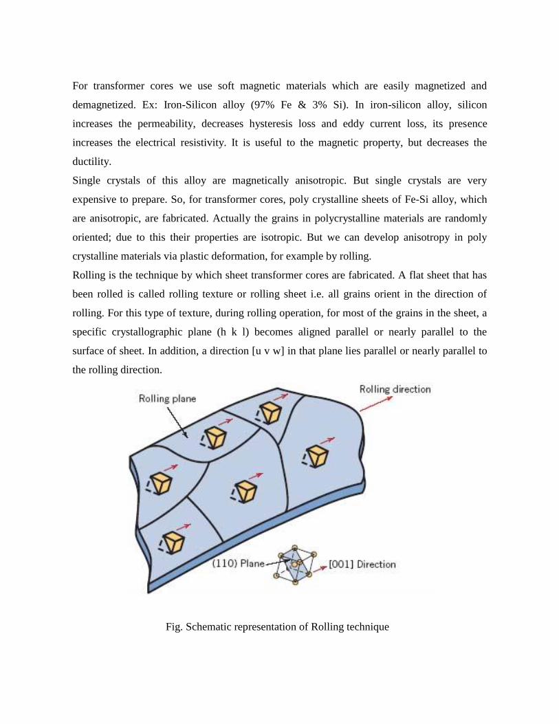
Rolling is the technique by which sheet transformer cores are fabricated. A flat sheet that has
been rolled is called rolling texture or rolling sheet i.e. all grains orient in the direction of
rolling. For this type of texture, during rolling operation, for most of the grains in the sheet, a
specific crystallographic plane (h k l) becomes aligned parallel or nearly parallel to the
surface of sheet. In addition, a direction [u v w] in that plane lies parallel or nearly parallel to
the rolling direction.
Fig. Schematic representation of Rolling technique
For body centred cubic alloys including Fe-Si alloy, the rolling texture is (1 1 0) [0 0 1].
Thus, a rolling texture is indicated by the plane-direction combination (h k l) [u v w]. For
body centred cubic alloys including Fe-Si alloy, the rolling texture is (1 1 0) [0 0 1]. Thus,
transformer cores of this iron-silicon alloy are fabricated such the direction in which the sheet
was rolled, is aligned parallel to the direction of applied magnetic field.
3.11 MOTORS
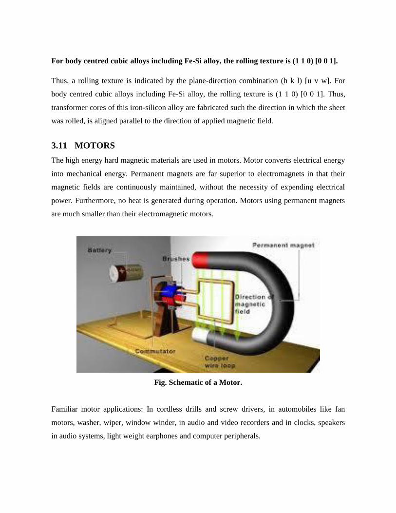
The high energy hard magnetic materials are used in motors. Motor converts electrical energy
into mechanical energy. Permanent magnets are far superior to electromagnets in that their
magnetic fields are continuously maintained, without the necessity of expending electrical
power. Furthermore, no heat is generated during operation. Motors using permanent magnets
are much smaller than their electromagnetic motors.
Fig. Schematic of a Motor.
Familiar motor applications: In cordless drills and screw drivers, in automobiles like fan
motors, washer, wiper, window winder, in audio and video recorders and in clocks, speakers
in audio systems, light weight earphones and computer peripherals.

3.13 PROBLEMS
1. Find the relative permeability of a ferromagnetic material if field strength of 220 A/m
produces a magnetization of 3300 A/m in it.
2. A paramagnetic material has a magnetic field intensity of 104 A/m. If the susceptibility
of the material at room temperature is 3.7 x 10⁻³
, calculate the magnetization and the
flux density in the material.
3. A circular loop of copper having a diameter of 10 cm carries a current of 500 mA.
Calculate the magnetic moment associated with the loop.
4. Calculate the saturation magnetization and saturation flux density for nickel, which
has a density of 8.90 g/cm3. Given that the Avogadro’s number is 6.023 x 10
23
atoms/mol and atomic weight of nickel is 58.71 g/mol.
5. A coil of wire 0.25 m long and having 400 turns carries a current of 15 A. a) What is
the magnitude of the magnetic field strength? b) Compute the flux density B if the coil
is in vacuum.
6. The magnetic flux density with in a bar of some material is 0.63 Tesla at an H field of
5 x 10⁵ A/m. Compute the following for this material a) The magnetic permeability b)
The magnetic susceptibility.
7. Compute a) Saturation magnetization b) Saturation flux density for iron, which has a
net magnetic moment per atom of 2.2 Bohr magnetons and a density of 7.87 g/cm3.
3.14 REVIEW QUESTIONS
1. What are paramagnetic and diamagnetic materials? Explain.
2. Explain how the magnetic materials are classified from the atomic point of view.
3. Write the differences between hard and soft magnetic materials.
4. Explain how ferrites are superior to ferromagnetic materials.
5. What are ferrites? Explain the magnetic properties of ferrites and mention their
applications.
6. Demonstrate that relative permeability and magnetic susceptibility are related to each
other.
7. Define magnetic moment. Explain the origin of magnetic moment at the atomic level.
What is Bohr magneton?
8. Write a short note on hysteresis curve.
9. Explain how hysteresis curve is used to classify magnetic materials.
10. What are ferromagnetic domains? Explain ferromagnetic domains with the help of
hysteresis curve.
11. Explain ferrimagnetism and anti ferromagnetism.
12. Define magnetization and show that .
13. Draw hysteresis loop and show that retentivity and coericivity in it.
14. Define energy product and give its importance in the case of permanent magnets.
15. Classify the magnetic materials based on their magnetic moment.
16. Define the terms permeability, magnetic susceptibility, magnetic flux density,
intensity of magnetic field, magnetization and magnetic moment.
17. Define the terms retentivity and coericivity.
18. What is meant by hysteresis loop and what do we infer from it.
19. What are the requirements of a transformer core material and electromagnet?
20. Define Bohr magneton.
21. Explain how the information is stored magnetically.
22. Explain why soft magnetic material is suitable for design of transformer core.
3.15 MULTIPLE CHOICE QUESTIONS
1. Magnetic materials in which permanent dipoles are absent are called
a) Paramagnetic b) Diamagnetic c) Ferromagnetic d) Ferrimagnetic
2. Magnetic materials in which the dipoles are aligned antiparallel to each other
a) Ferromagnetic b) Diamagnetic c) Ferrimagnetic d) Antiferromagnetic
3. Spontaneous magnetization is present in ________ magnetic materials
a) Dia& Para b) Ferro &Antiferro c) Ferri& Ferro d) Ferro & Para
4. Ferrimagnetic materials are
a) Conductors b) Semiconductors c) Superconductors d) Ceramics

5. Susceptibility of diamagnetic materials is
a) Positive & small b) Positive & large c) Negative & small d) all the above
6. Soft magnetic materials have ______ hysteresis loop area
a) Large b) Small c) Medium d) Cant’ say
7. The units of magnetic field intensity are
a) Am-1
b) Hm-1
c) Wbm-1
d) no units
8. The units of magnetic flux density is
a) Am-1
b) Hm-1
c) Tesla d) Am2
9. Magnetic materials having square shaped hysteresis loop is
a) Diamagnetic b) Paramagnetic c) Antiferromagnetic d) Ferrimagnetic
10. The boundary between domains is called ______ wall
a) Domain b) Potential c) Bloch d) both a & c
11. A paramagnetic material has a magnetic field intensity of 104 A/m. If the susceptibility
of the material at room temperature is 3.7 x 10⁻³
. Then the magnetisation of the
material is _____ A/m
a) 37 b) 57 c) 67 d) 77
12. For antiferromagnetic materials the magnetic susceptibility is maximum at ___
temperature
a) Fermi b) Debye c) Neel d) Curie
13. Magnetic permeability represents the _____ with which a material allows magnetic
lines of force to pass through it
a) Difficult b) Easy c) both a & b d) None
14. Magnetic moment per unit volume of material is called
a)Permeability b)Flux density c)Magnetisation d)Magnetic field intensity
15. Ferrites are _______ materials
a) Ferromagnetic b) Ferroelectric c) Ferroelectric d) Ferrimagnetic
16. The magnetic field strength of silicon is 1000 A/m. If the magnetic susceptibility is -
0.25 x 10⁻⁵
, the flux density in silicon is ______ x 10-3
Wb/m2.

a) 1.25 b) 12.5 c) 125 d) 0.125
17. The magnetisation inside a certain material is 1.4 T when the material is placed inside
a magnetic field of value 6.5 x 10⁻⁴
T the relative permeability of the material is
a) 2000 b) 2001 c) 20000 d) 20001
18. Relative permeability is related to magnetic susceptibility by
a) μr = 1 - א b) μr = 1 - א c) μr = 1 + א d) μr = 1 / א
19. One Bohr magneton is equal to
a) 9.27x10⁻²⁴
A-m2 b)9.1x10
-31 A- m
2 c)9.27x10
-14 A- m
2 d)9.1x10
-24 A- m
2
20. Bohr magneton is a unit for measuring
a) Susceptibility b) Permeability c) Magnetic moment d) Flux density
21. The magnetization retained by the specimen when the magnetizaing field is reduced
from saturation value to zero is known as
a) Coercivity b) Hysteresis c) Retentivity d) Spontaneous magnetisation
22. In which of the following materials the magnetisation is non linearly related to applied
magnetic field
a) Ferromagnetic b) Paramagnetic c) Diamagnetic d) both a & b
23. In which of the following magnetic materials the magnetisation is linearly related to
applied magnetic field
a) Ferro & Para b) Para &Dia c) Dia& Ferro d) All the above
24. The relation between magnetic flux density, applied magnetic field and magnetisation
is
a) B = µo(H+M) b) B = µo(H-M) c) M = µo(H+B) d) H = µo(B+M)
25. Compared with ferromagnetic materials ferrimagnetic materials have
a) More conductivity b) More resistivity c) More susceptibility d) More
permeability
26. The area of the hysteresis loop of a ferromagnetic material gives
a) The coercive force b) The remanent flux density c) The intensity of magnetisation
of the material d) Energy spent in magnetising and demagnetising a material.
27. Of the following materials which are used for making permanent magnets
a) SmCo b) Alnico c) Carbon steel d) All the above
28. The temperature below which certain materials are antiferromagnetic and above which
they are paramagnetic is called ______ temperature
a) Curie b) Neel c) Transition d) Weiss
29. Below the ferromagnetic Curie temperature the ferromagnetic material exhibits B-H
curve in the form of
a) Straight line b) Exponential curve c) Either a or b d) B-H loop
30.The relative permeability of a ferromagnetic material if field of strength 220 amp/meter
produces a magnetisation 3300 amp/ meter in it is
a) 16 b) 160 c) 0.16 d) 1.6


