Download - 3-2 Spot Welding

8/2/2019 3-2 Spot Welding
http://slidepdf.com/reader/full/3-2-spot-welding 1/24
Spot Welding

8/2/2019 3-2 Spot Welding
http://slidepdf.com/reader/full/3-2-spot-welding 2/24
Definition of Resistance
Welding
• Resistance welding is a fusion welding process in
which coalescence of metals is produced at the
faying surfaces by the heat generated at the joint by
the resistance of the work to the flow of electricity.
• Force is applied before, during, and after the
application of current to prevent arcing at the work
piece.
• Melting occurs at the faying surfaces during
welding.

8/2/2019 3-2 Spot Welding
http://slidepdf.com/reader/full/3-2-spot-welding 3/24
Principal Types of Resistance Welds
Electrodesor WeldingTips
Electrodesor WeldingWheels
Electrodesor Dies
ProjectionWelds
Electrodes or Dies
Spot Weld Seam Weld Projection Weld
Upset Weld Flash Weld
After Welding After Welding[Reference: Resistance Welding Manual, RWMA, p.1-3]

8/2/2019 3-2 Spot Welding
http://slidepdf.com/reader/full/3-2-spot-welding 4/24
Typical Equipment of Resistance Spot Welding
(a) (b)
[Reference: Welding Process Slides, The Welding Institute]

8/2/2019 3-2 Spot Welding
http://slidepdf.com/reader/full/3-2-spot-welding 5/24
Advantages of Resistance Spot
Welding Adaptability for Automation in High-Rate
Production of Sheet Metal Assemblies
High Speed
Economical
Dimensional Accuracy

8/2/2019 3-2 Spot Welding
http://slidepdf.com/reader/full/3-2-spot-welding 6/24
Limitations of Resistance Spot
Welding Difficulty for maintenance or repair
Adds weight and material cost to the product, compared witha butt joint
Generally have higher cost than most arc welding equipment
Produces unfavorable line power demands
Low tensile and fatigue strength
The full strength of the sheet cannot prevail across a spotwelded joint
Eccentric loading condition

8/2/2019 3-2 Spot Welding
http://slidepdf.com/reader/full/3-2-spot-welding 7/24
Resistance Welding
• Resistance welding depends on threefactors:
– Time of current flow (T).
– Resistance of the conductor (R)
– Amperage (I).
•
Heat generation is expressed asQ = I2R T, Q = Heat generated.

8/2/2019 3-2 Spot Welding
http://slidepdf.com/reader/full/3-2-spot-welding 8/24
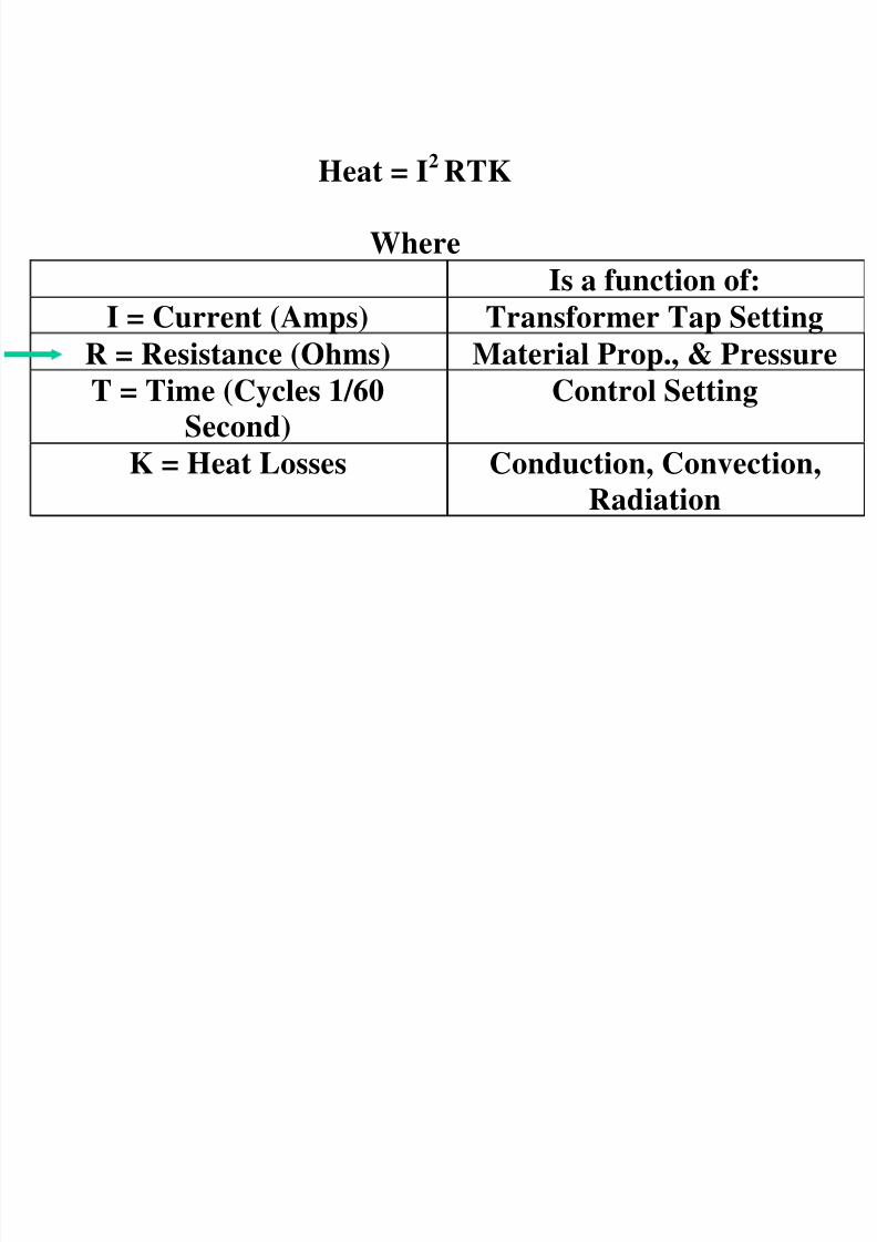
Heat = I2 RTK
Where
Is a function of:
I = Current (Amps) Transformer Tap Setting
R = Resistance (Ohms) Material Prop., & Pressure
T = Time (Cycles 1/60
Second)
Control Setting
K = Heat Losses Conduction, Convection,Radiation

8/2/2019 3-2 Spot Welding
http://slidepdf.com/reader/full/3-2-spot-welding 9/24
Heating Value of Current = RMS Current
Irms=0.707 Ipeak

8/2/2019 3-2 Spot Welding
http://slidepdf.com/reader/full/3-2-spot-welding 10/24
Block Diagram of Single-Phase
Spot Welder
Spot Weld
Main Power Line
Contactor

8/2/2019 3-2 Spot Welding
http://slidepdf.com/reader/full/3-2-spot-welding 11/24
N=np /ns
Vs= Vp /N
Is = Ip N
8/2/2019 3-2 Spot Welding
http://slidepdf.com/reader/full/3-2-spot-welding 12/24
Heat = I2 RTK
Where
Is a function of:
I = Current (Amps) Transformer Tap SettingR = Resistance (Ohms) Material Prop., & Pressure
T = Time (Cycles 1/60
Second)
Control Setting
K = Heat Losses Conduction, Convection,Radiation

8/2/2019 3-2 Spot Welding
http://slidepdf.com/reader/full/3-2-spot-welding 13/24
Contact-Resistance Measurement
ContactArea
Electrode Force
Electrode Force
Small Current
Rec
Rec
Rsc
Rv
Rv
Rec
Rec
Rtotal
Rec = contact resistancebetween electrode
and sheet surface
Rsc = contact resistanceat the faying surface
Rv = volume resistance ofthe sheets

8/2/2019 3-2 Spot Welding
http://slidepdf.com/reader/full/3-2-spot-welding 14/24
Factors Affecting Heat
Generation (Q):
• Welding pressure
– as welding pressure increases both
R and Q decrease.
• Electrodes
– deformation of electrodes
increases contact area. As contactarea increases, both R and Q
decrease.

8/2/2019 3-2 Spot Welding
http://slidepdf.com/reader/full/3-2-spot-welding 15/24
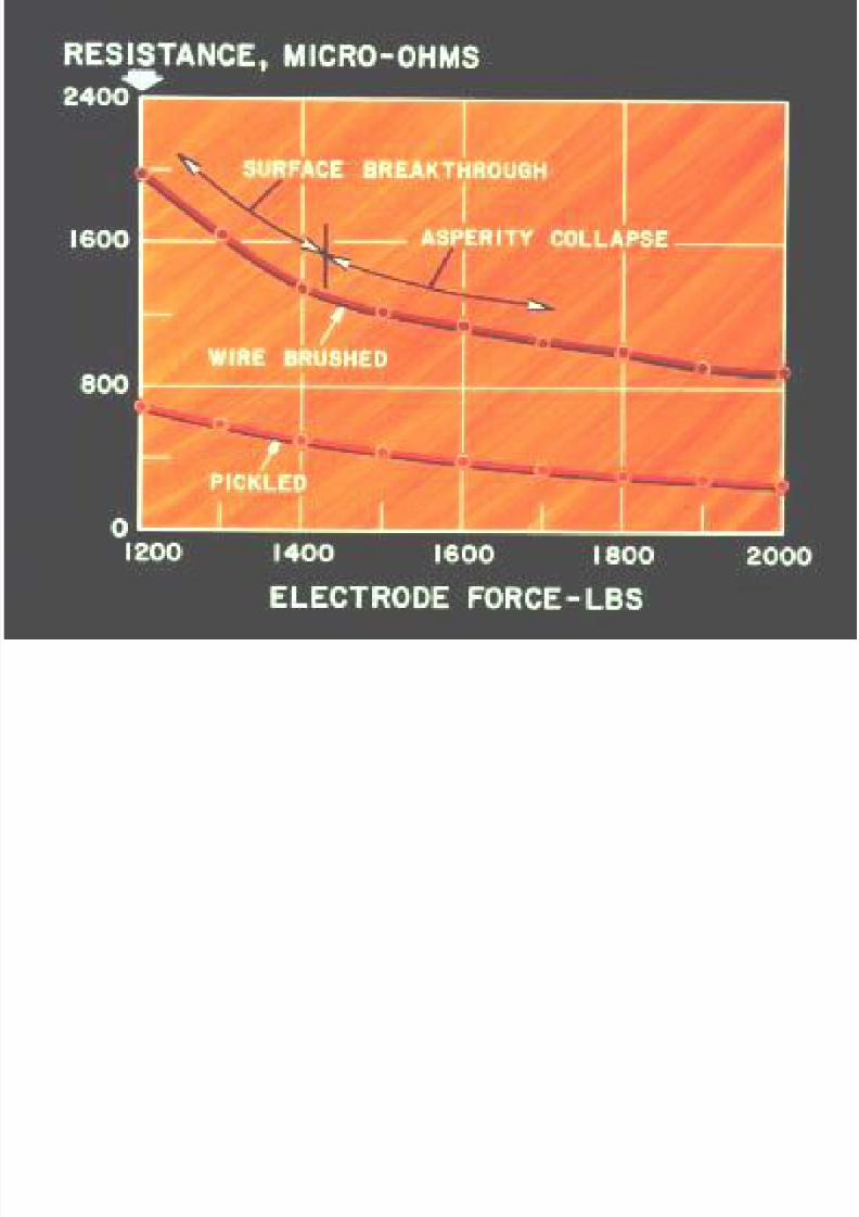
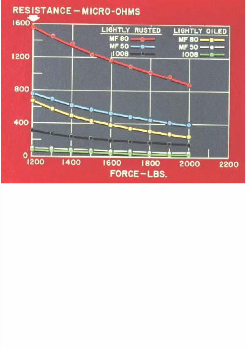
Surface ConditionSteel
Steel
Steel
Steel
Oils/DirtOxide
OxideOils/Dirt
(a) Pickled Conditions
(b) Rusted ConditionsRusty
Pickled
Polished
Electrode Force
R e s i s t i v i t y

8/2/2019 3-2 Spot Welding
http://slidepdf.com/reader/full/3-2-spot-welding 16/24
Resistance Varies with Pressure
Low Pressure Medium Pressure High Pressure
(a) (b) (c)
8/2/2019 3-2 Spot Welding
http://slidepdf.com/reader/full/3-2-spot-welding 17/24

8/2/2019 3-2 Spot Welding
http://slidepdf.com/reader/full/3-2-spot-welding 18/24
Volume-Resistance Measurement
ContactArea
Electrode Force
Electrode Force
Small Current
Rec
Rec
Rsc
Rv
Rv
Rv
Rtotal
Rec = contact resistancebetween electrode
and sheet surface
Rsc = contact resistanceat the faying surface
Rv = volume resistance ofthe sheets
8/2/2019 3-2 Spot Welding
http://slidepdf.com/reader/full/3-2-spot-welding 19/24

8/2/2019 3-2 Spot Welding
http://slidepdf.com/reader/full/3-2-spot-welding 20/24
Resistivity as a Function of Temperature
100 200 300 400 500 600 700 800
10
2030
405060708090
100110120
130
HSLA
Low Carbon
Temperature, °C
R
e s i s t i v i t y , m W
- c m
[Reference: Welding in the Automotive Industry, D.W. Dickinson, p.125]

8/2/2019 3-2 Spot Welding
http://slidepdf.com/reader/full/3-2-spot-welding 21/24
Heat Dissipation
Weld Nugget
Water-Cooled Copper Alloy Electrode
Water-Cooled Copper Alloy Electrode
Base Metal
Base Metal

8/2/2019 3-2 Spot Welding
http://slidepdf.com/reader/full/3-2-spot-welding 22/24
Initial Resistance Through Weldment
Top ElectrodeWater
WeldNugget
Bottom Electrode
Resistance
D i s t a n c e

8/2/2019 3-2 Spot Welding
http://slidepdf.com/reader/full/3-2-spot-welding 23/24
Temperature Readings of A Spot Welding Process
Workpiece
This illustration was takenabout 4/60th of a secondafter the welding currentstarts.
(Note: Temp at Electrode Sheet Interface Higher than Bulk)

8/2/2019 3-2 Spot Welding
http://slidepdf.com/reader/full/3-2-spot-welding 24/24
After 20%
welding time
At the end of
welding time
Temperature
E l e c t r o d e
W o r k p i e c e
Temperature
distribution at
various
location
during
welding.
Temperature Distribution


