2G Mobile Communication Systems 2G Review: GSM
Services Architecture Protocols Call setup Mobility management Security
HSCSD
GPRS Architecture Protocols QoS
EDGE
UMTS Networks 2Andreas Mitschele-Thiel, Jens Mückenheim Oct-08
References
Jochen Schiller: Mobile Communications (German and English), Addison-Wesley, 2000(most of the material covered in this chapter is based on the book)
Michel Mouly, Marie-Bernadette Pautet: The GSM System for Mobile Communications. Telecom Pub, Juni 1992
Jörg Eberspaecher, u. a.: GSM Switching, Services and Protocols. John Wiley and Sons Ltd, 2001
Siegmund Redl, u. a.: GSM and Personal Communications Handbook. Artech House, 1998
Gunnar Heine: GSM Networks: Protocols, Terminology, and Implementation. Artech House Mobile Communications Library. Artech House Publishers, 1998
UMTS Networks 3Andreas Mitschele-Thiel, Jens Mückenheim Oct-08
GSM - Global System for Mobile Communication Pan-European standard
(set by ETSI, European Telecommunications Standardisation Institute) simultaneous introduction of essential services in three phases (1991, 1994,
1996) by the European telecommunication administrations seamless roaming within Europe and worldwide via multimode terminals
GSM is one of the fastest growing communications technology of all time The billionth GSM user was connected in Q1 2004 - just a dozen years after the
commercial launch of the first GSM networks [Projection in 1989: 13 million subscribers in Europe in 2005]
The second billionth GSM user was connected in Q2 2006 - just two and a half years after the first billion
GSM accounts for 82% of the global mobile market (2007) 29% of the global population use GSM technology (2007) The GSM Association (www.gsmworld.com ) currently has operator members in
218 countries and territories. in Germany (2007): 81 mio subscribers in 4 networks:
T-Mobile (D1) and Vodafone (D2), E-plus and O2 23 billion SMS per year (350 SMS per user per year)
o
UMTS Networks 4Andreas Mitschele-Thiel, Jens Mückenheim Oct-08
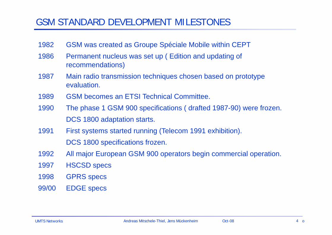
1982 GSM was created as Groupe Spéciale Mobile within CEPT1986 Permanent nucleus was set up ( Edition and updating of
recommendations)1987 Main radio transmission techniques chosen based on prototype
evaluation.1989 GSM becomes an ETSI Technical Committee.1990 The phase 1 GSM 900 specifications ( drafted 1987-90) were frozen.
DCS 1800 adaptation starts.1991 First systems started running (Telecom 1991 exhibition).
DCS 1800 specifications frozen.1992 All major European GSM 900 operators begin commercial operation.1997 HSCSD specs1998 GPRS specs99/00 EDGE specs
GSM STANDARD DEVELOPMENT MILESTONES
o
UMTS Networks 5Andreas Mitschele-Thiel, Jens Mückenheim Oct-08
GSM compared to 1G Systems
Communication mobile, wireless communication; support for voice and data services
Total mobility international access, chip-card enables use of access points of
different providersWorldwide connectivity one number, the network handles localization
High capacity better frequency efficiency, smaller cells, more customers per cell
High transmission quality high audio quality and reliability for wireless, uninterrupted phone
calls at higher speeds (e.g. from cars, trains, etc.) by digital transmission
Security functions access control, authentication via chip-card (SIM) and PIN
o
UMTS Networks 6Andreas Mitschele-Thiel, Jens Mückenheim Oct-08
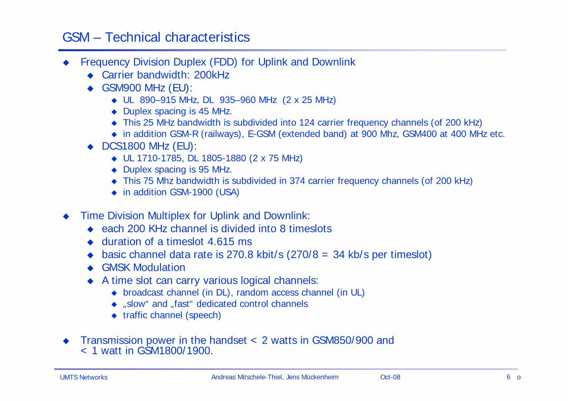
GSM – Technical characteristics
Frequency Division Duplex (FDD) for Uplink and Downlink Carrier bandwidth: 200kHz GSM900 MHz (EU):
UL 890–915 MHz, DL 935–960 MHz (2 x 25 MHz) Duplex spacing is 45 MHz. This 25 MHz bandwidth is subdivided into 124 carrier frequency channels (of 200 kHz) in addition GSM-R (railways), E-GSM (extended band) at 900 Mhz, GSM400 at 400 MHz etc.
DCS1800 MHz (EU): UL 1710-1785, DL 1805-1880 (2 x 75 MHz) Duplex spacing is 95 MHz. This 75 Mhz bandwidth is subdivided in 374 carrier frequency channels (of 200 kHz) in addition GSM-1900 (USA)
Time Division Multiplex for Uplink and Downlink: each 200 KHz channel is divided into 8 timeslots duration of a timeslot 4.615 ms basic channel data rate is 270.8 kbit/s (270/8 = 34 kb/s per timeslot) GMSK Modulation A time slot can carry various logical channels:
broadcast channel (in DL), random access channel (in UL) „slow“ and „fast“ dedicated control channels traffic channel (speech)
Transmission power in the handset < 2 watts in GSM850/900 and < 1 watt in GSM1800/1900.
o
UMTS Networks 7Andreas Mitschele-Thiel, Jens Mückenheim Oct-08
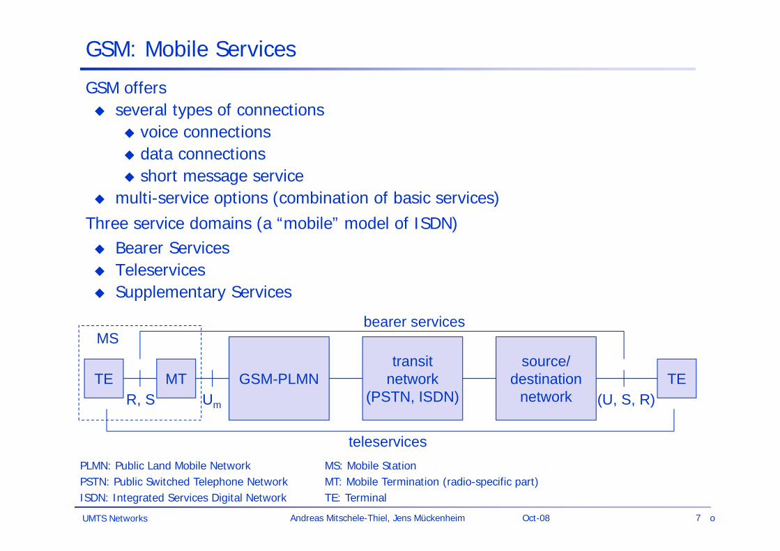
GSM: Mobile Services
GSM offers several types of connections
voice connections data connections short message service
multi-service options (combination of basic services)Three service domains (a “mobile” model of ISDN) Bearer Services Teleservices Supplementary Services
GSM-PLMNtransit
network(PSTN, ISDN)
source/destination
networkTE TE
bearer services
teleservices
R, S (U, S, R)Um
MT
MS
PLMN: Public Land Mobile NetworkPSTN: Public Switched Telephone NetworkISDN: Integrated Services Digital Network
MS: Mobile StationMT: Mobile Termination (radio-specific part)TE: Terminal
o
UMTS Networks 8Andreas Mitschele-Thiel, Jens Mückenheim Oct-08
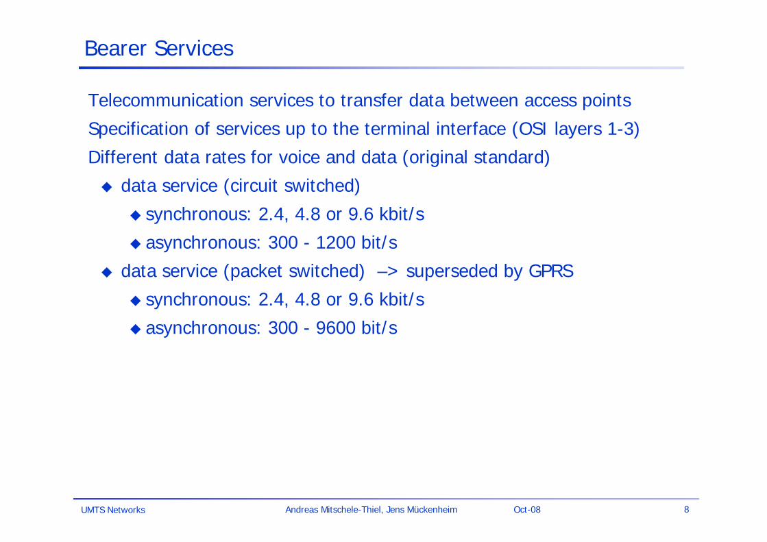
Bearer Services
Telecommunication services to transfer data between access points
Specification of services up to the terminal interface (OSI layers 1-3)
Different data rates for voice and data (original standard)
data service (circuit switched)
synchronous: 2.4, 4.8 or 9.6 kbit/s
asynchronous: 300 - 1200 bit/s
data service (packet switched) –> superseded by GPRS
synchronous: 2.4, 4.8 or 9.6 kbit/s
asynchronous: 300 - 9600 bit/s
UMTS Networks 9Andreas Mitschele-Thiel, Jens Mückenheim Oct-08
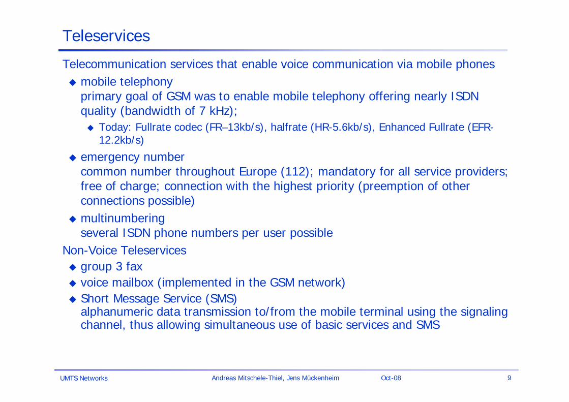
Teleservices
Telecommunication services that enable voice communication via mobile phones mobile telephony
primary goal of GSM was to enable mobile telephony offering nearly ISDN quality (bandwidth of 7 kHz); Today: Fullrate codec (FR–13kb/s), halfrate (HR-5.6kb/s), Enhanced Fullrate (EFR-
12.2kb/s)
emergency numbercommon number throughout Europe (112); mandatory for all service providers; free of charge; connection with the highest priority (preemption of other connections possible)
multinumberingseveral ISDN phone numbers per user possible
Non-Voice Teleservices group 3 fax voice mailbox (implemented in the GSM network) Short Message Service (SMS)
alphanumeric data transmission to/from the mobile terminal using the signaling channel, thus allowing simultaneous use of basic services and SMS

UMTS Networks 10Andreas Mitschele-Thiel, Jens Mückenheim Oct-08
Supplementary services
Services in addition to the basic services
cannot be offered stand-alone
similar to ISDN services besides lower bandwidth due to the radio link
may differ between different service providers, countries and protocol versions
Important services
call forwarding
identification: forwarding of caller number
suppression of number forwarding (CLIP, CLIR)
automatic call-back
conferencing with up to 7 participants
locking of the mobile terminal (incoming or outgoing calls)
...
UMTS Networks 11Andreas Mitschele-Thiel, Jens Mückenheim Oct-08
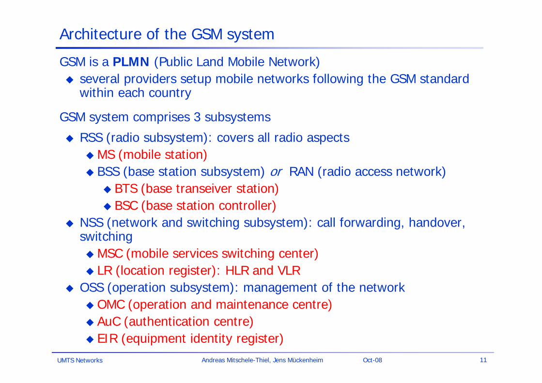
Architecture of the GSM system
GSM is a PLMN (Public Land Mobile Network) several providers setup mobile networks following the GSM standard
within each country
GSM system comprises 3 subsystems
RSS (radio subsystem): covers all radio aspectsMS (mobile station) BSS (base station subsystem) or RAN (radio access network)
BTS (base transeiver station) BSC (base station controller)
NSS (network and switching subsystem): call forwarding, handover, switchingMSC (mobile services switching center) LR (location register): HLR and VLR
OSS (operation subsystem): management of the networkOMC (operation and maintenance centre) AuC (authentication centre) EIR (equipment identity register)
UMTS Networks 12Andreas Mitschele-Thiel, Jens Mückenheim Oct-08
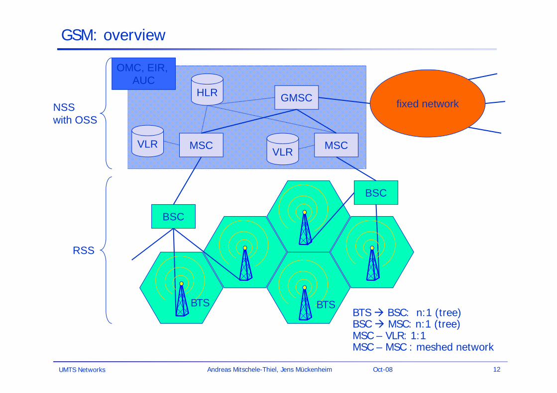
GSM: overview
fixed network
BSC
BSC
MSC MSC
GMSC
OMC, EIR, AUC
VLR
HLRNSSwith OSS
RSS
VLR
BTS BTSBTS BSC: n:1 (tree)BSC MSC: n:1 (tree)MSC – VLR: 1:1MSC – MSC : meshed network
UMTS Networks 13Andreas Mitschele-Thiel, Jens Mückenheim Oct-08
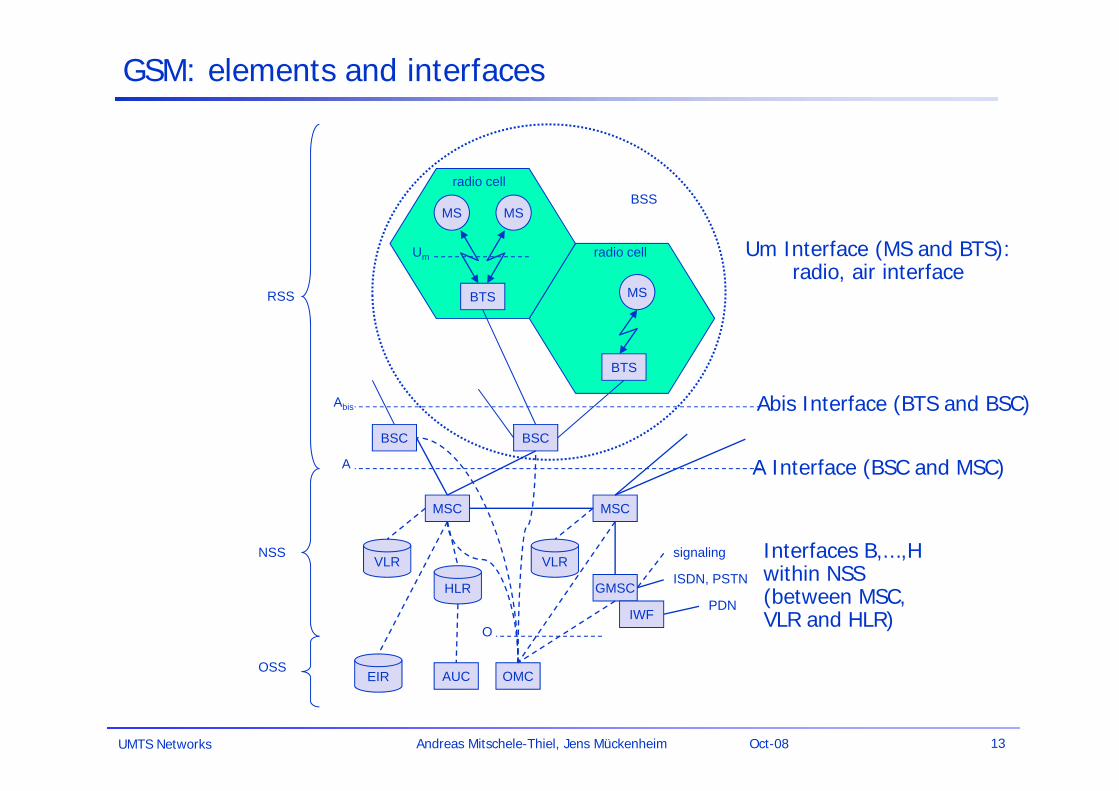
GSM: elements and interfaces
NSS
MS MS
BTS
BSC
GMSC
IWF
OMC
BTS
BSC
MSC MSC
Abis
Um
EIR
HLR
VLR VLR
A
BSS
PDN
ISDN, PSTN
RSS
radio cell
radio cell
MS
AUCOSS
signaling
O
Um Interface (MS and BTS):radio, air interface
Abis Interface (BTS and BSC)
Interfaces B,...,H within NSS (between MSC, VLR and HLR)
A Interface (BSC and MSC)
UMTS Networks 14Andreas Mitschele-Thiel, Jens Mückenheim Oct-08
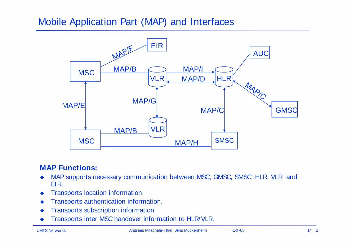
MSC
SMSC
GMSC
EIRAUC
MAP/B
MSC
MAP/E
VLR
VLRMAP/B
MAP/G
HLRMAP/IMAP/D
MAP/H
MAP/C
Mobile Application Part (MAP) and Interfaces
MAP Functions: MAP supports necessary communication between MSC, GMSC, SMSC, HLR, VLR and
EIR. Transports location information. Transports authentication information. Transports subscription information Transports inter MSC handover information to HLR/VLR.
o
UMTS Networks 15Andreas Mitschele-Thiel, Jens Mückenheim Oct-08
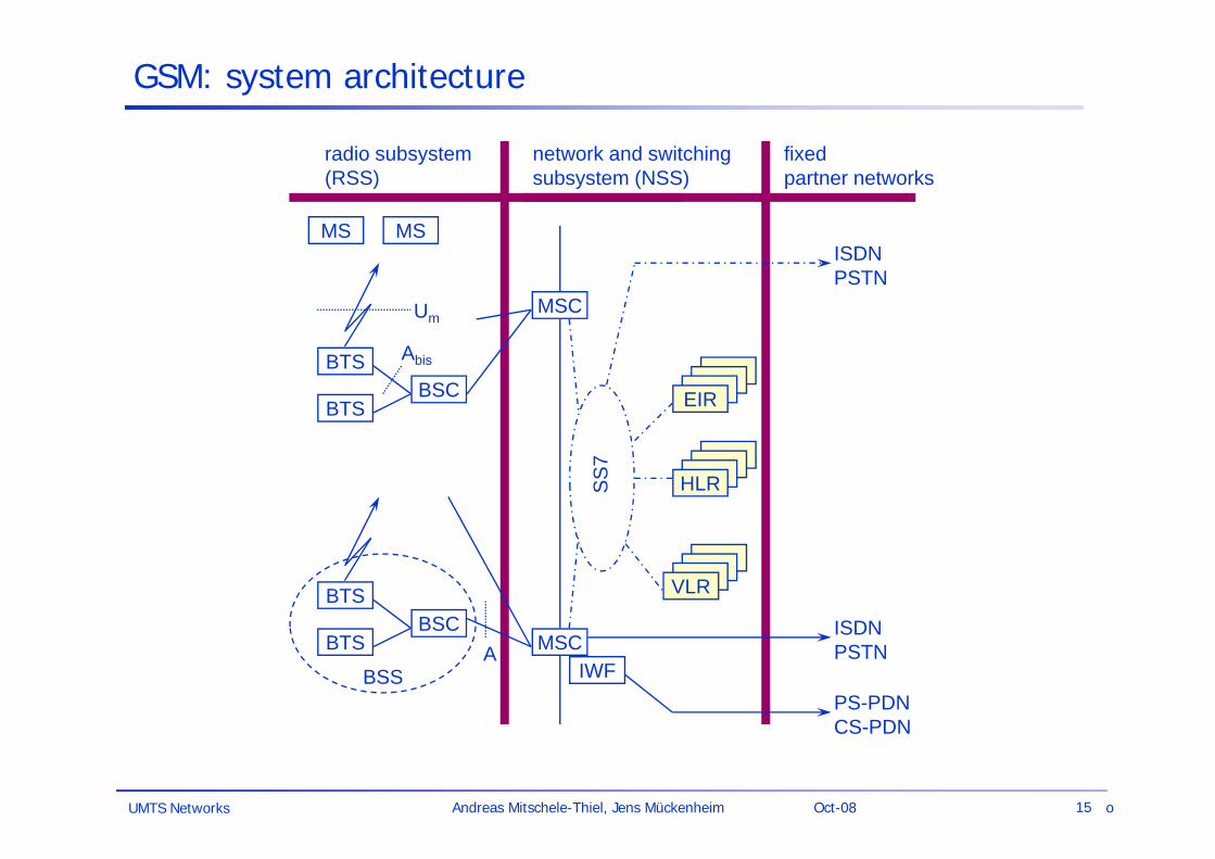
Um
Abis
ABSS
radio subsystem (RSS)
MS MS
BTSBSC
BTS
BTSBSC
BTS
network and switching subsystem (NSS)
MSC
MSC
fixedpartner networks
IWF
ISDNPSTN
PS-PDNCS-PDN
SS7
EIR
HLR
VLR
ISDNPSTN
GSM: system architecture
o
UMTS Networks 16Andreas Mitschele-Thiel, Jens Mückenheim Oct-08
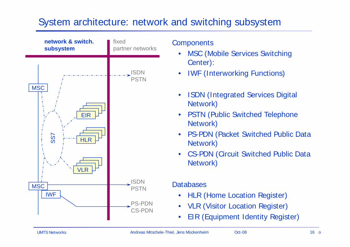
System architecture: network and switching subsystem
Components• MSC (Mobile Services Switching
Center):• IWF (Interworking Functions)
• ISDN (Integrated Services Digital Network)
• PSTN (Public Switched Telephone Network)
• PS-PDN (Packet Switched Public Data Network)
• CS-PDN (Circuit Switched Public Data Network)
Databases• HLR (Home Location Register)• VLR (Visitor Location Register)• EIR (Equipment Identity Register)
network & switch.subsystem
MSC
MSC
fixed partner networks
IWF
ISDNPSTN
PS-PDNCS-PDN
SS7
EIR
HLR
VLR
ISDNPSTN
o
UMTS Networks 17Andreas Mitschele-Thiel, Jens Mückenheim Oct-08
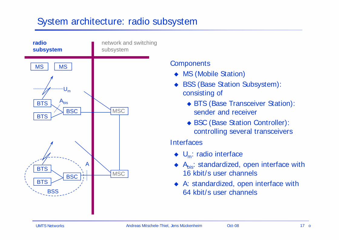
System architecture: radio subsystem
Components MS (Mobile Station) BSS (Base Station Subsystem):
consisting of BTS (Base Transceiver Station):
sender and receiver BSC (Base Station Controller):
controlling several transceiversInterfaces
Um: radio interface Abis: standardized, open interface with
16 kbit/s user channels A: standardized, open interface with
64 kbit/s user channels
Um
Abis
A
BSS
radiosubsystem
network and switchingsubsystem
MS MS
BTSBSC MSC
BTS
BTSBSC
BTSMSC
o
UMTS Networks 18Andreas Mitschele-Thiel, Jens Mückenheim Oct-08
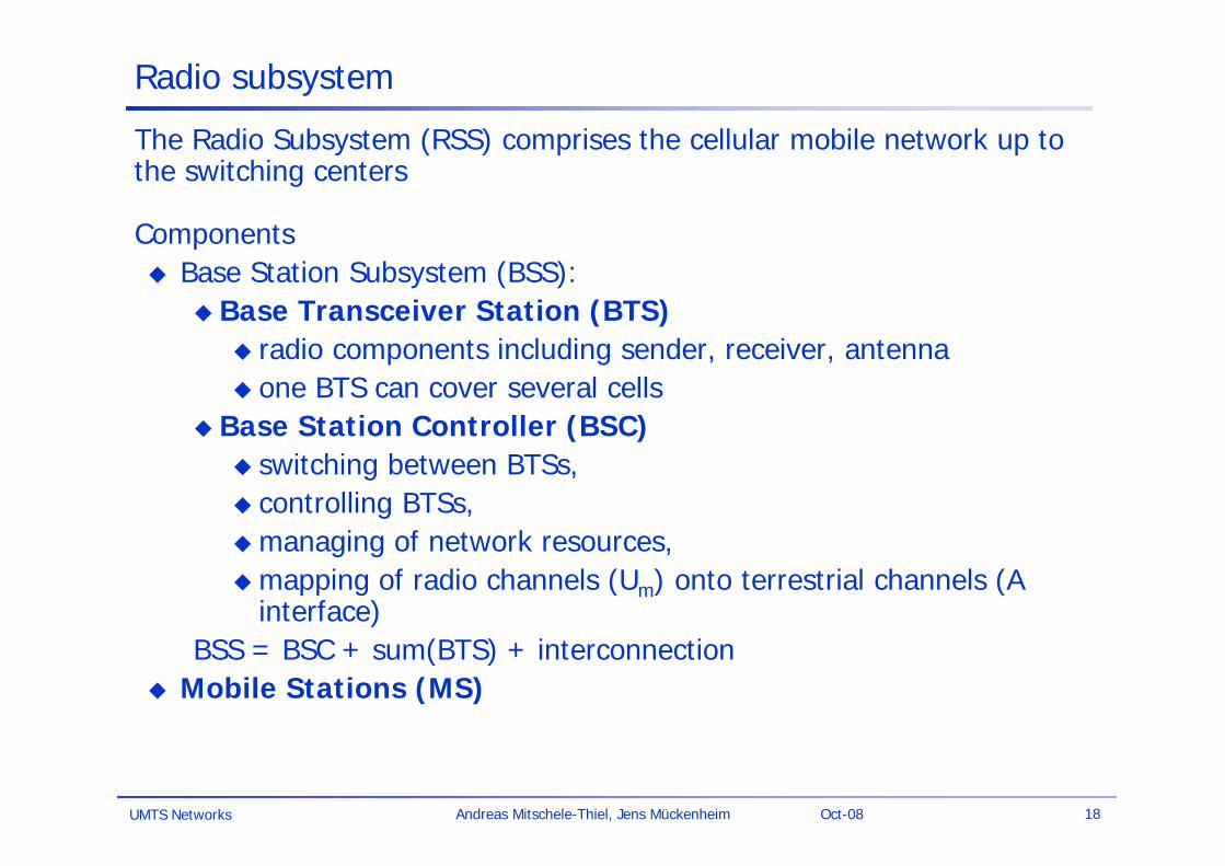
Radio subsystem
The Radio Subsystem (RSS) comprises the cellular mobile network up to the switching centers
Components Base Station Subsystem (BSS):
Base Transceiver Station (BTS) radio components including sender, receiver, antenna one BTS can cover several cells
Base Station Controller (BSC) switching between BTSs, controlling BTSs, managing of network resources, mapping of radio channels (Um) onto terrestrial channels (A
interface)BSS = BSC + sum(BTS) + interconnection
Mobile Stations (MS)
UMTS Networks 19Andreas Mitschele-Thiel, Jens Mückenheim Oct-08
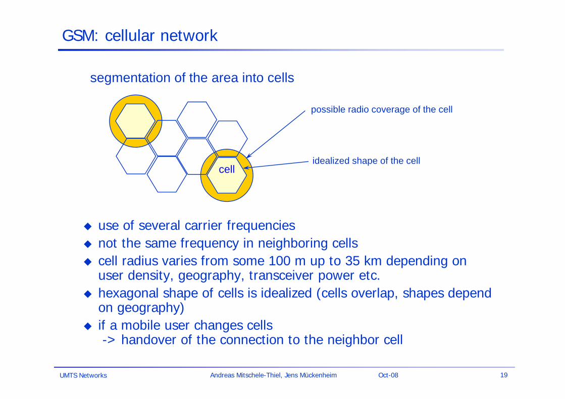
possible radio coverage of the cell
idealized shape of the cellcell
segmentation of the area into cells
GSM: cellular network
use of several carrier frequencies not the same frequency in neighboring cells cell radius varies from some 100 m up to 35 km depending on
user density, geography, transceiver power etc. hexagonal shape of cells is idealized (cells overlap, shapes depend
on geography) if a mobile user changes cells
-> handover of the connection to the neighbor cell
UMTS Networks 20Andreas Mitschele-Thiel, Jens Mückenheim Oct-08
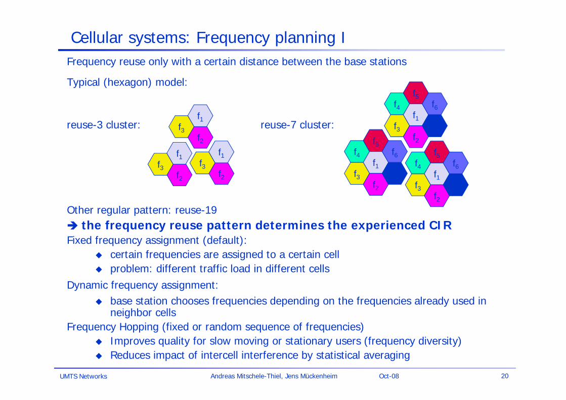
Cellular systems: Frequency planning IFrequency reuse only with a certain distance between the base stations
Typical (hexagon) model:
reuse-3 cluster: reuse-7 cluster:
Other regular pattern: reuse-19 the frequency reuse pattern determines the experienced CIR Fixed frequency assignment (default):
certain frequencies are assigned to a certain cell problem: different traffic load in different cells
Dynamic frequency assignment: base station chooses frequencies depending on the frequencies already used in
neighbor cellsFrequency Hopping (fixed or random sequence of frequencies)
Improves quality for slow moving or stationary users (frequency diversity) Reduces impact of intercell interference by statistical averaging
f4f5
f1f3
f2
f6
f7
f4f5
f1f3
f2
f6
f7
f4f5
f1f3
f2
f6
f7f2
f1f3
f2
f1f3
f2
f1f3
UMTS Networks 21Andreas Mitschele-Thiel, Jens Mückenheim Oct-08
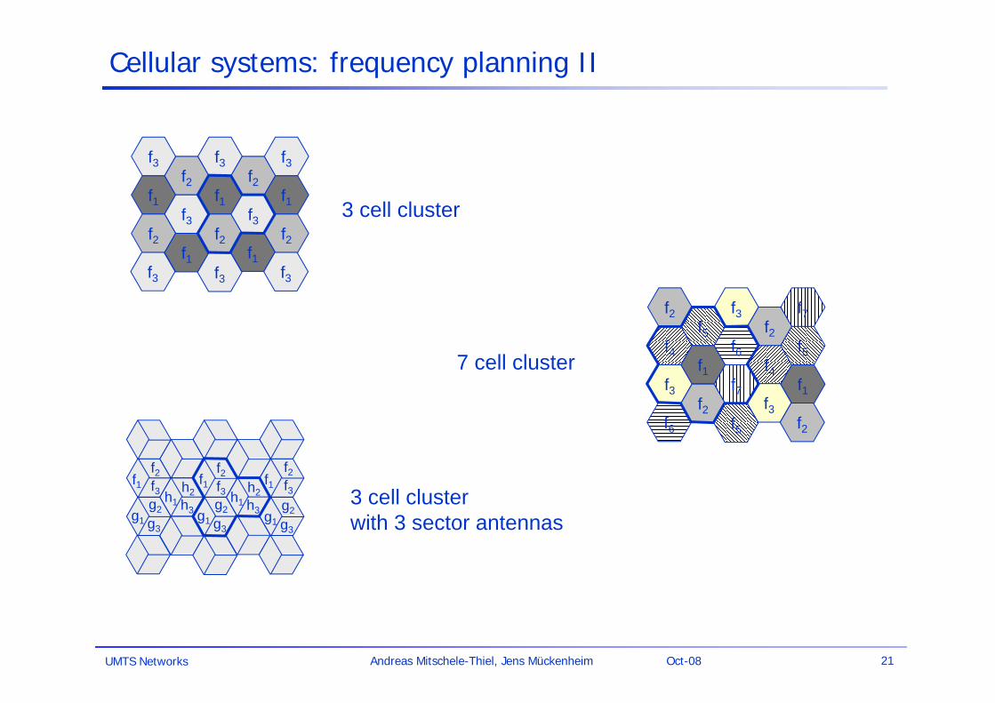
Cellular systems: frequency planning II
f1f2
f3f2
f1
f1
f2
f3f2
f3f1
f2f1
f3f3
f3f3
f3
f4f5
f1f3
f2
f6
f7
f3f2
f4f5
f1f3
f5f6
f7f2
f2
f1f1 f1f2f3
f2f3
f2f3h1
h2h3g1
g2
g3
h1h2h3g1
g2
g3g1
g2
g3
3 cell cluster
7 cell cluster
3 cell clusterwith 3 sector antennas
UMTS Networks 22Andreas Mitschele-Thiel, Jens Mückenheim Oct-08
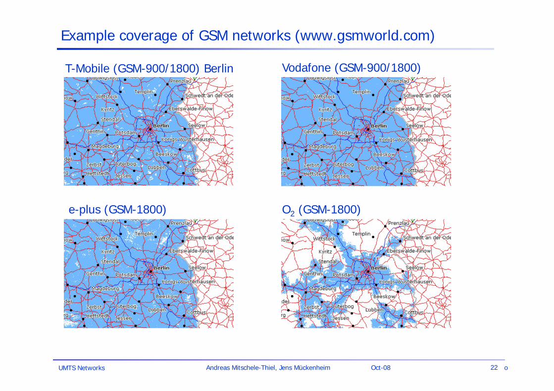
Example coverage of GSM networks (www.gsmworld.com)
e-plus (GSM-1800)
T-Mobile (GSM-900/1800) Berlin
O2 (GSM-1800)
Vodafone (GSM-900/1800)
o
UMTS Networks 23Andreas Mitschele-Thiel, Jens Mückenheim Oct-08
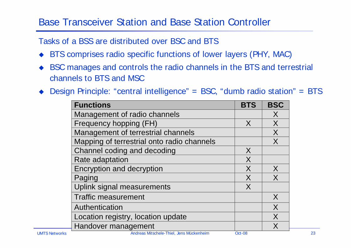
Base Transceiver Station and Base Station Controller
Tasks of a BSS are distributed over BSC and BTS
BTS comprises radio specific functions of lower layers (PHY, MAC)
BSC manages and controls the radio channels in the BTS and terrestrial channels to BTS and MSC
Design Principle: “central intelligence” = BSC, “dumb radio station” = BTS
Functions BTS BSCManagement of radio channels XFrequency hopping (FH) X XManagement of terrestrial channels XMapping of terrestrial onto radio channels XChannel coding and decoding XRate adaptation XEncryption and decryption X XPaging X XUplink signal measurements XTraffic measurement XAuthentication XLocation registry, location update XHandover management X

UMTS Networks 24Andreas Mitschele-Thiel, Jens Mückenheim Oct-08
GSM: Air Interface
FDMA (Frequency Division Multiple Access) / FDD (Frequency Division Duplex)
1 2 3 123124. . .
890 MHz 915 MHz
1 2 3 123124. . .
935 MHz 960 MHz
200 kHz
Uplink Downlink
frequency
TDMA (Time Division Multiple Access)
time
Downlink
87654321
4,615 ms = 1250 bit
Uplink
87654321
UMTS Networks 25Andreas Mitschele-Thiel, Jens Mückenheim Oct-08
Framing Modulation(GMSK)
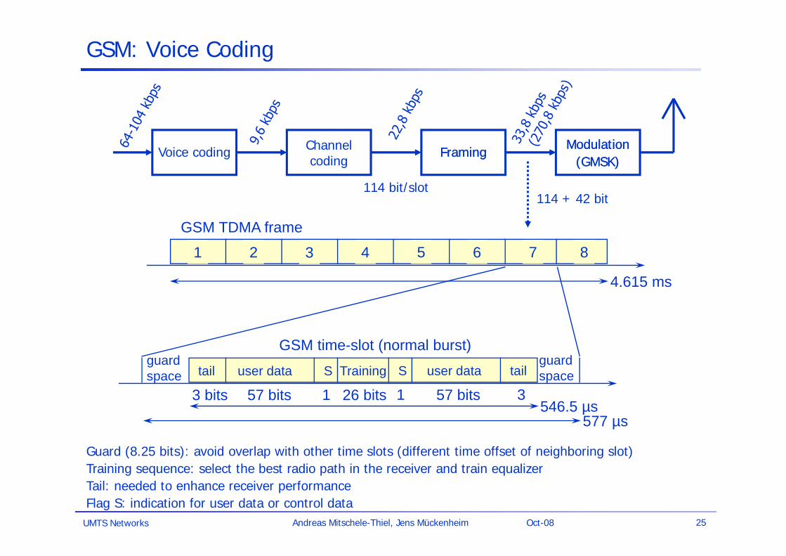
GSM: Voice Coding
Voice coding Channelcoding
Framing Modulation(GMSK)
114 bit/slot114 + 42 bit
Guard (8.25 bits): avoid overlap with other time slots (different time offset of neighboring slot)Training sequence: select the best radio path in the receiver and train equalizerTail: needed to enhance receiver performanceFlag S: indication for user data or control data
1 2 3 4 5 6 7 8
GSM TDMA frame
GSM time-slot (normal burst)
4.615 ms
546.5 µs577 µs
tail user data TrainingSguardspace S user data tail
guardspace
3 bits 57 bits 26 bits 57 bits1 1 3
UMTS Networks 26Andreas Mitschele-Thiel, Jens Mückenheim Oct-08
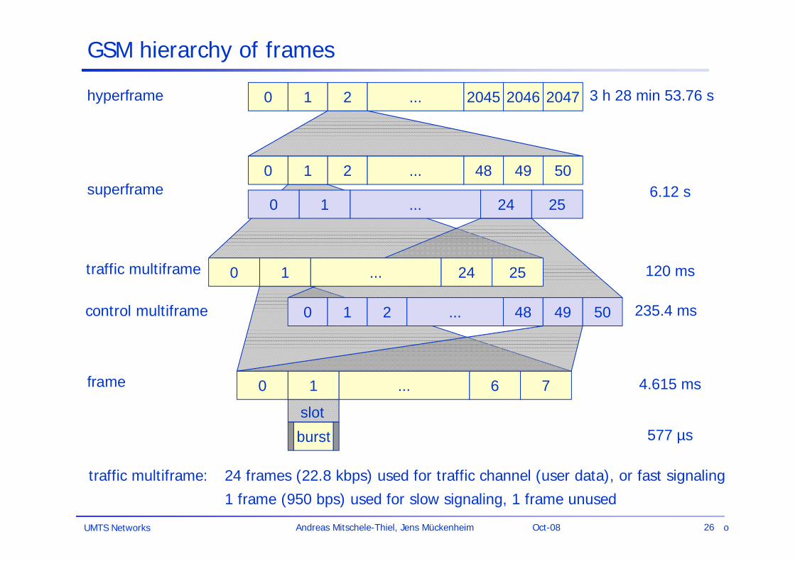
GSM hierarchy of frames
0 1 2 2045 2046 2047...hyperframe
0 1 2 48 49 50...superframe
0 1 6 7...frame
burstslot
577 µs
4.615 ms
120 ms
6.12 s
3 h 28 min 53.76 s
traffic multiframe
0 1 24 25...
0 1 2 48 49 50... 235.4 mscontrol multiframe
0 1 24 25...
traffic multiframe: 24 frames (22.8 kbps) used for traffic channel (user data), or fast signaling
1 frame (950 bps) used for slow signaling, 1 frame unused
o
UMTS Networks 27Andreas Mitschele-Thiel, Jens Mückenheim Oct-08
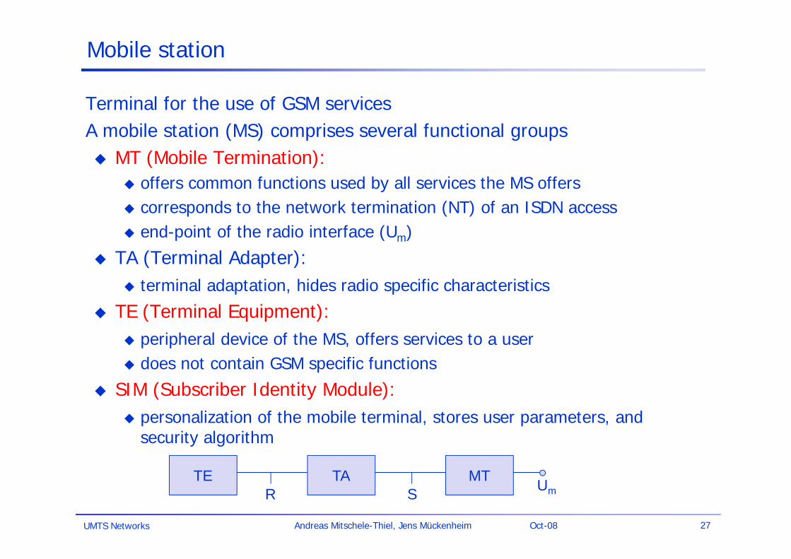
Mobile station
Terminal for the use of GSM servicesA mobile station (MS) comprises several functional groups MT (Mobile Termination):
offers common functions used by all services the MS offers corresponds to the network termination (NT) of an ISDN access end-point of the radio interface (Um)
TA (Terminal Adapter): terminal adaptation, hides radio specific characteristics
TE (Terminal Equipment): peripheral device of the MS, offers services to a user does not contain GSM specific functions
SIM (Subscriber Identity Module): personalization of the mobile terminal, stores user parameters, and
security algorithm
R S UmTE TA MT
UMTS Networks 28Andreas Mitschele-Thiel, Jens Mückenheim Oct-08
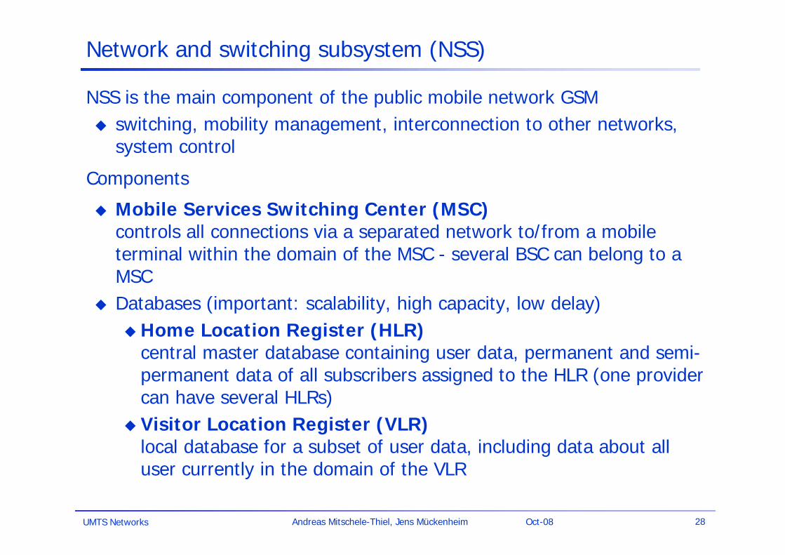
Network and switching subsystem (NSS)
NSS is the main component of the public mobile network GSM switching, mobility management, interconnection to other networks,
system control
Components
Mobile Services Switching Center (MSC)controls all connections via a separated network to/from a mobile terminal within the domain of the MSC - several BSC can belong to a MSC
Databases (important: scalability, high capacity, low delay)Home Location Register (HLR)
central master database containing user data, permanent and semi-permanent data of all subscribers assigned to the HLR (one provider can have several HLRs)
Visitor Location Register (VLR)local database for a subset of user data, including data about all user currently in the domain of the VLR
UMTS Networks 29Andreas Mitschele-Thiel, Jens Mückenheim Oct-08
Mobile Services Switching Center (MSC)
The MSC plays a central role in GSM switching functions (of traffic channels) additional control functions for mobility support management of network resources interworking functions via Gateway MSC (GMSC) integration of several databases
Functions of a MSC
specific functions for paging and call forwarding termination of SS7 (signaling system no. 7), subscriber signalling to
BSS mobility-specific signaling location registration and forwarding of location information provision of new services (fax, data calls) support of short message service (SMS) generation and forwarding of accounting and billing information
UMTS Networks 30Andreas Mitschele-Thiel, Jens Mückenheim Oct-08
Operation subsystem
The OSS (Operation Subsystem) enables centralized operation, management, and maintenance of all GSM subsystems
Components
Authentication Center (AUC) generates user-specific authentication parameters on request of a VLR
authentication parameters used for authentication of mobile terminals and encryption of user data on the air interface within the GSM system
Equipment Identity Register (EIR) registers GSM mobile stations and user rights
stolen or malfunctioning mobile stations can be locked and sometimes even localized
Operation and Maintenance Center (OMC) different control capabilities for the radio subsystem and the network
subsystem
Basic Functions in GSM Systems
Connection Setup Handover Location management Roaming Authentication
UMTS Networks 32Andreas Mitschele-Thiel, Jens Mückenheim Oct-08
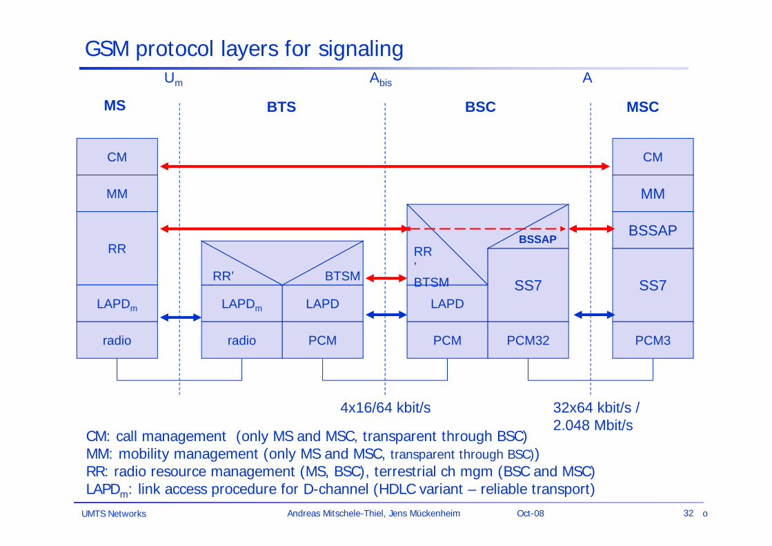
GSM protocol layers for signaling
CM
MM
RR
MM
LAPDm
radio
LAPDm
radio
LAPD
PCM
RR’ BTSM
CM
LAPD
PCM
RR’BTSM
4x16/64 kbit/s
Um Abis A
SS7
PCM32
SS7
PCM3
32x64 kbit/s /2.048 Mbit/s
MS BTS BSC MSC
BSSAP BSSAP
CM: call management (only MS and MSC, transparent through BSC)MM: mobility management (only MS and MSC, transparent through BSC))RR: radio resource management (MS, BSC), terrestrial ch mgm (BSC and MSC)LAPDm: link access procedure for D-channel (HDLC variant – reliable transport)
o

UMTS Networks 33Andreas Mitschele-Thiel, Jens Mückenheim Oct-08
Connection Setup & Radio Resource Assignment
BSBSC MSC
UMTS Networks 34Andreas Mitschele-Thiel, Jens Mückenheim Oct-08
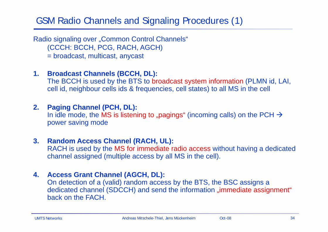
GSM Radio Channels and Signaling Procedures (1)
Radio signaling over „Common Control Channels“ (CCCH: BCCH, PCG, RACH, AGCH) = broadcast, multicast, anycast
1. Broadcast Channels (BCCH, DL):The BCCH is used by the BTS to broadcast system information (PLMN id, LAI, cell id, neighbour cells ids & frequencies, cell states) to all MS in the cell
2. Paging Channel (PCH, DL): In idle mode, the MS is listening to „pagings“ (incoming calls) on the PCH power saving mode
3. Random Access Channel (RACH, UL):RACH is used by the MS for immediate radio access without having a dedicated channel assigned (multiple access by all MS in the cell).
4. Access Grant Channel (AGCH, DL):On detection of a (valid) random access by the BTS, the BSC assigns a dedicated channel (SDCCH) and send the information „immediate assignment“back on the FACH.
UMTS Networks 35Andreas Mitschele-Thiel, Jens Mückenheim Oct-08
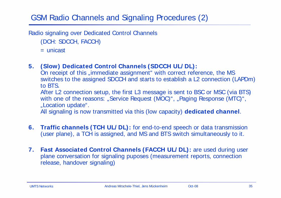
GSM Radio Channels and Signaling Procedures (2)
Radio signaling over Dedicated Control Channels (DCH: SDCCH, FACCH) = unicast
5. (Slow) Dedicated Control Channels (SDCCH UL/DL):On receipt of this „immediate assignment“ with correct reference, the MS switches to the assigned SDCCH and starts to establish a L2 connection (LAPDm) to BTS.After L2 connection setup, the first L3 message is sent to BSC or MSC (via BTS) with one of the reasons: „Service Request (MOC)“, „Paging Response (MTC)“, „Location update“. All signaling is now transmitted via this (low capacity) dedicated channel.
6. Traffic channels (TCH UL/DL): for end-to-end speech or data transmission (user plane), a TCH is assigned, and MS and BTS switch simultaneously to it.
7. Fast Associated Control Channels (FACCH UL/DL): are used during user plane conversation for signaling puposes (measurement reports, connection release, handover signaling)
UMTS Networks 36Andreas Mitschele-Thiel, Jens Mückenheim Oct-08
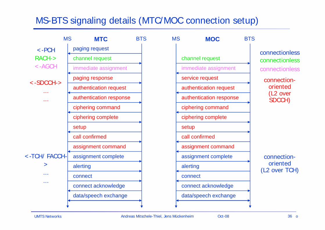
MS-BTS signaling details (MTC/MOC connection setup)
BTSMS
paging request
channel request
immediate assignment
paging response
authentication request
authentication response
ciphering command
ciphering complete
setup
call confirmed
assignment command
assignment complete
alerting
connect
connect acknowledge
data/speech exchange
BTSMS
channel request
immediate assignment
service request
authentication request
authentication response
ciphering command
ciphering complete
setup
call confirmed
assignment command
assignment complete
alerting
connect
connect acknowledge
data/speech exchange
MTC MOC
<-PCHRACH-><-AGCH
<-SDCCH->......
<-TCH/ FACCH->......
connectionless
connection-oriented
(L2 over TCH)
connection-oriented (L2 over SDCCH)
connectionless
connectionless
o
UMTS Networks 37Andreas Mitschele-Thiel, Jens Mückenheim Oct-08
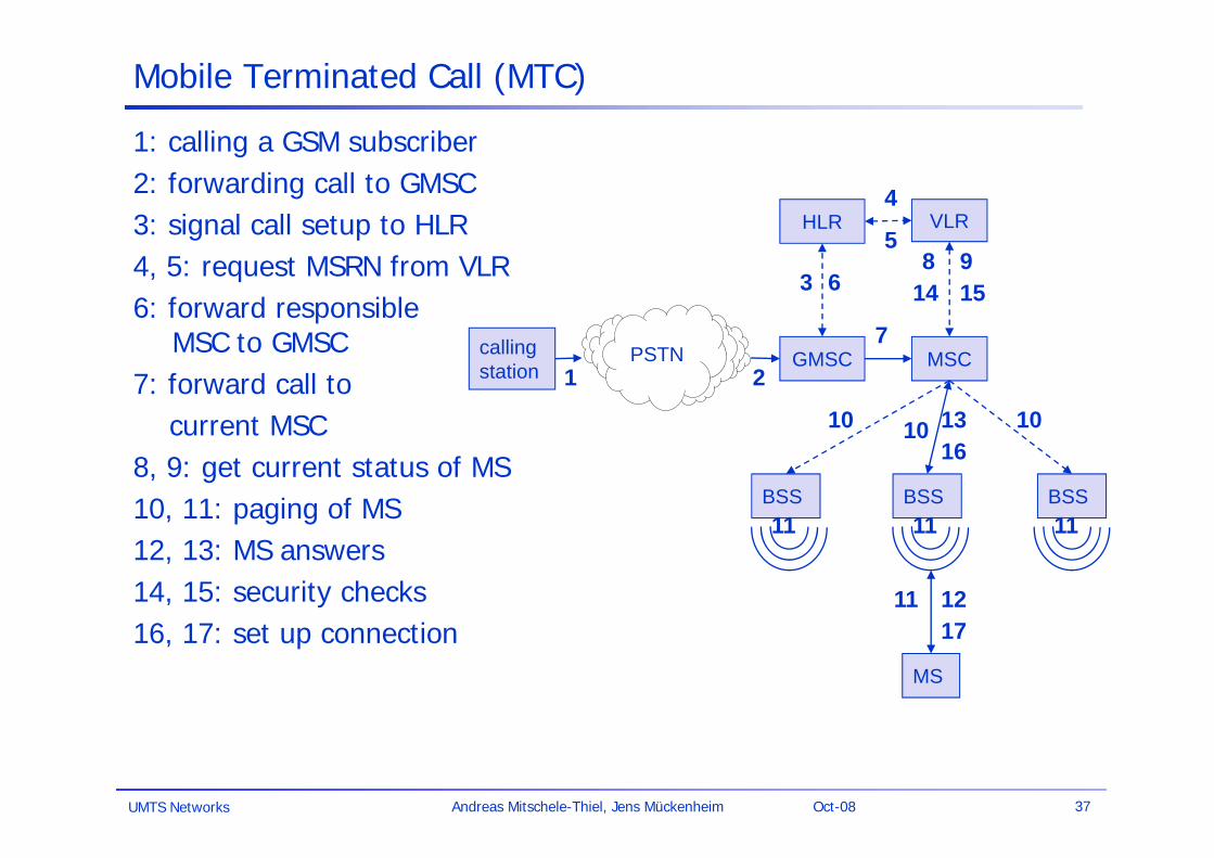
Mobile Terminated Call (MTC)
PSTNcallingstation GMSC
HLR VLR
BSSBSSBSS
MSC
MS
1 2
3
4
5
6
7
8 9
10
11 12
1316
10 10
11 11 11
14 15
17
1: calling a GSM subscriber2: forwarding call to GMSC3: signal call setup to HLR4, 5: request MSRN from VLR6: forward responsible
MSC to GMSC7: forward call to
current MSC8, 9: get current status of MS10, 11: paging of MS12, 13: MS answers14, 15: security checks16, 17: set up connection
UMTS Networks 38Andreas Mitschele-Thiel, Jens Mückenheim Oct-08
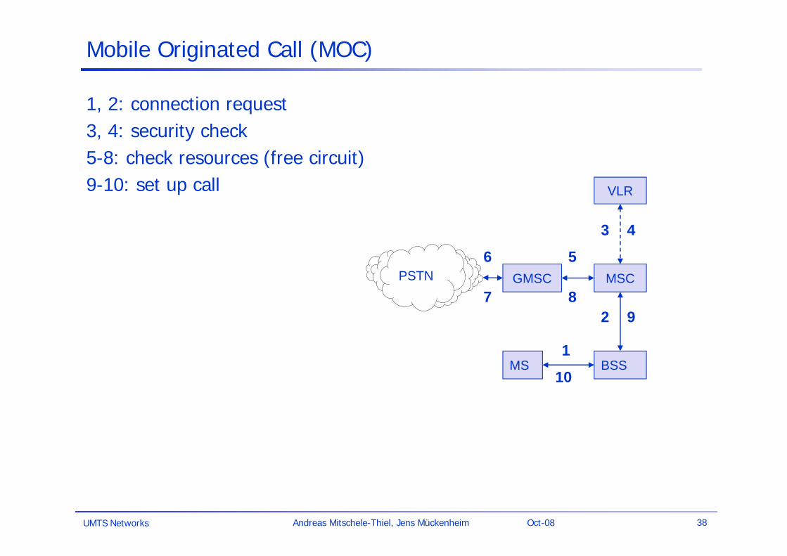
Mobile Originated Call (MOC)
PSTN GMSC
VLR
BSS
MSC
MS1
2
6 5
3 4
9
10
7 8
1, 2: connection request3, 4: security check5-8: check resources (free circuit)9-10: set up call
UMTS Networks 39Andreas Mitschele-Thiel, Jens Mückenheim Oct-08
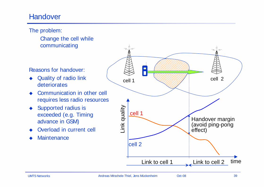
Handover
The problem:Change the cell while communicating
Reasons for handover: Quality of radio link
deteriorates Communication in other cell
requires less radio resources Supported radius is
exceeded (e.g. Timing advance in GSM)
Overload in current cell Maintenance
Link
qua
lity
Link to cell 1 Link to cell 2 time
cell 1
cell 2
Handover margin (avoid ping-pong effect)
cell 1 cell 2
UMTS Networks 40Andreas Mitschele-Thiel, Jens Mückenheim Oct-08
X
BSBS
Before
X
BSBS
During
X
BSBS
After
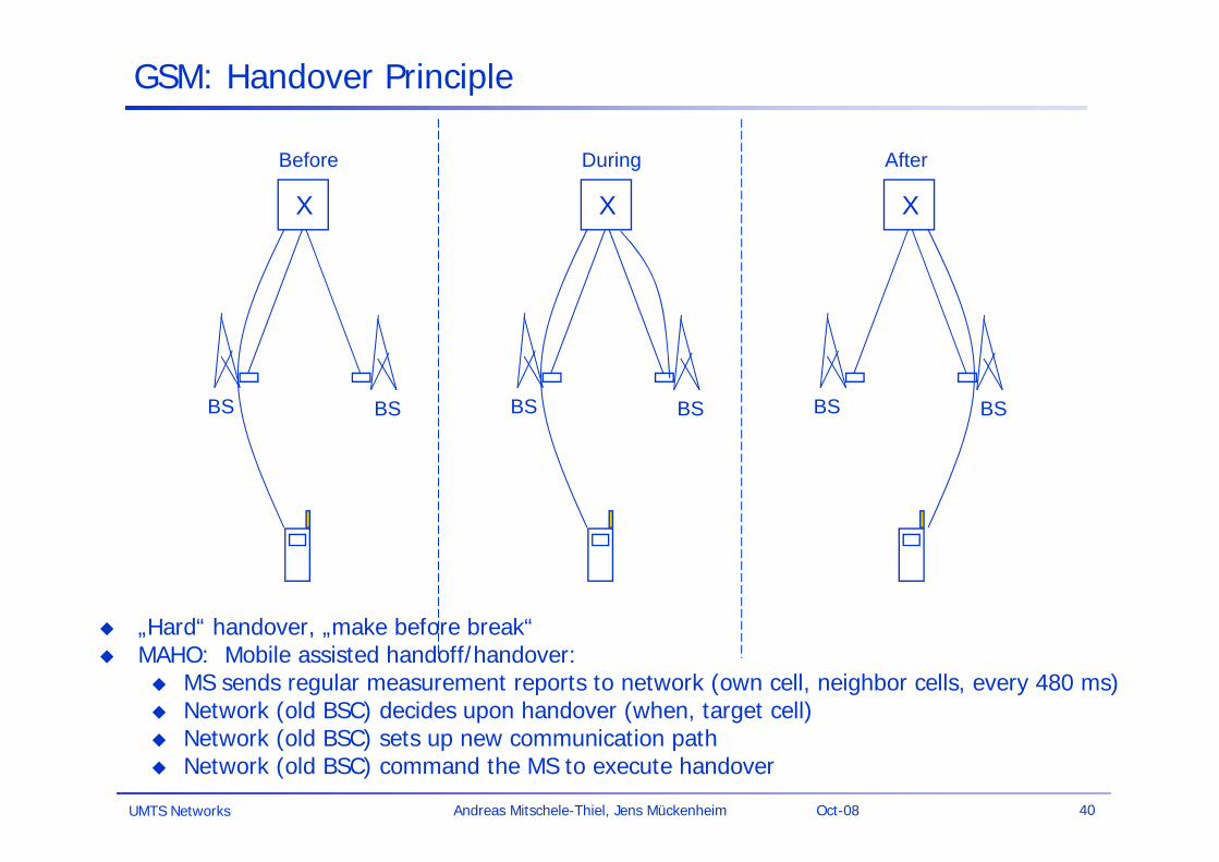
GSM: Handover Principle
„Hard“ handover, „make before break“ MAHO: Mobile assisted handoff/handover:
MS sends regular measurement reports to network (own cell, neighbor cells, every 480 ms) Network (old BSC) decides upon handover (when, target cell) Network (old BSC) sets up new communication path Network (old BSC) command the MS to execute handover
UMTS Networks 41Andreas Mitschele-Thiel, Jens Mückenheim Oct-08
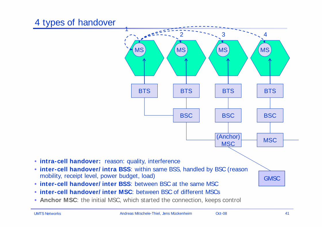
4 types of handover
(Anchor)MSC MSC
BSC BSCBSC
BTS BTS BTSBTS
MS MS MS MS
12 3 4
• intra-cell handover: reason: quality, interference• inter-cell handover/intra BSS: within same BSS, handled by BSC (reason
mobility, receipt level, power budget, load)• inter-cell handover/inter BSS: between BSC at the same MSC• inter-cell handover/inter MSC: between BSC of different MSCs• Anchor MSC: the initial MSC, which started the connection, keeps control
GMSC
UMTS Networks 42Andreas Mitschele-Thiel, Jens Mückenheim Oct-08
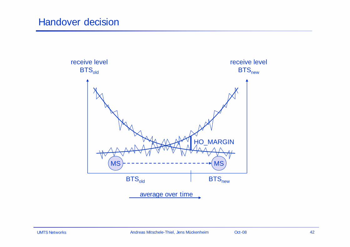
Handover decision
receive levelBTSold
receive levelBTSnew
MS MS
HO_MARGIN
BTSold BTSnew
average over time
UMTS Networks 43Andreas Mitschele-Thiel, Jens Mückenheim Oct-08
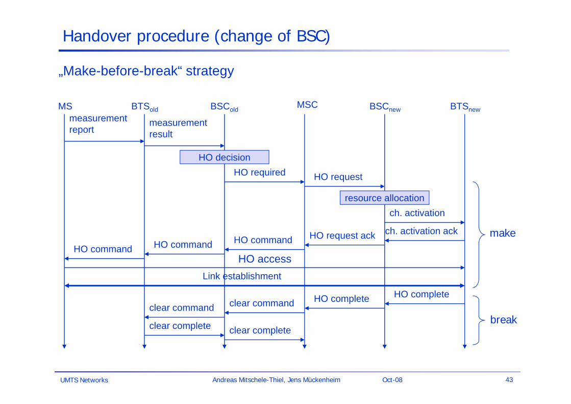
Handover procedure (change of BSC)
HO access
BTSold BSCnew
measurementresult
BSCold
Link establishment
MSCMSmeasurementreport
HO decisionHO required
BTSnew
HO request
resource allocationch. activation
ch. activation ackHO request ackHO commandHO commandHO command
HO completeHO completeclear commandclear command
clear complete clear complete
„Make-before-break“ strategy
make
break
UMTS Networks 44Andreas Mitschele-Thiel, Jens Mückenheim Oct-08
Location Management / Mobility Management
The problem: locate a mobile user from the network side without an actice call/connection
(e.g for an incoming mobile-terminated call)
Two extreme solutions:
Mobile registers with each visited cell(e.g. direct call to the hotel room to reach a person)– signaling traffic to register mobile when cell is changed– network has to maintain location information about each mobile+ low signaling load to page mobile (i.e. in one cell only)
Page mobile using a network- or worldwide broadcast message(e.g. broadcast on TV or radio to contact a person)– heavy signaling load to page the mobile (i.e. in all cells)+ no signaling traffic while mobile is idle
UMTS Networks 45Andreas Mitschele-Thiel, Jens Mückenheim Oct-08
RA
RA
RA RA
RA
RA RA
RA
RA
LocationUpdate
LocationUpdate
LocationUpdate
LocationUpdate
LocationUpdate
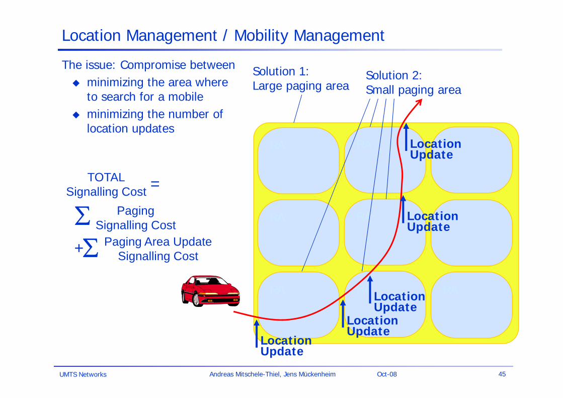
Location Management / Mobility Management
The issue: Compromise between minimizing the area where
to search for a mobile minimizing the number of
location updates
Solution 1:Large paging area
Solution 2:Small paging area
PagingSignalling Cost
Paging Area UpdateSignalling Cost
TOTALSignalling Cost
+
=
UMTS Networks 46Andreas Mitschele-Thiel, Jens Mückenheim Oct-08
Roaming
The problem: Use a network not subscribed to
Roaming agreement needed between network operators to exchange information concerning: Authentication Authorisation Accounting
Examples of roaming agreements: International Roaming: Use available network abroad National Roaming (exception):
Use of T-Mobile network by O2 (E2) subscribers in area with no O2 coverage
UMTS Networks 47Andreas Mitschele-Thiel, Jens Mückenheim Oct-08
Security in GSM
Security service System was designed with a moderate level of security to authenticate the
subscriber using a pre-shared key and challenge-response. access control/authentication
user SIM (Subscriber Identity Module): secret PIN (personal identification number)
SIM network: challenge response method no authentication of network!
confidentiality voice and signaling encrypted on the wireless link (after successful authentication)
anonymity temporary identity TMSI
(Temporary Mobile Subscriber Identity) newly assigned at each new location update encrypted transmission
3 algorithms specified in GSM A3 for authentication (“secret”, open interface) A5 for encryption (standardized) A8 for key generation (“secret”, open interface)
“secret”:• A3 and A8
available in the Internet
• network providers can use stronger mechanisms
UMTS Networks 48Andreas Mitschele-Thiel, Jens Mückenheim Oct-08
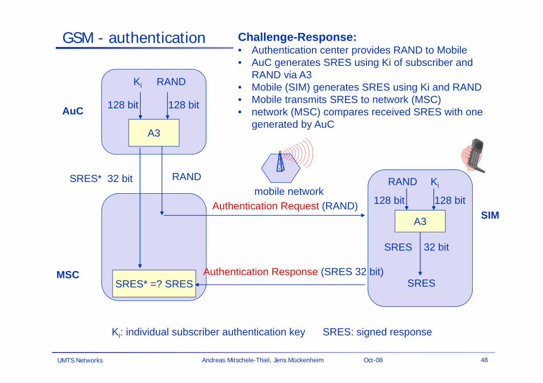
GSM - authentication
A3
RANDKi
128 bit 128 bit
RAND
SRES* =? SRES
A3
RAND Ki
128 bit 128 bit
SRES 32 bit
SRES
Authentication Request (RAND)
Authentication Response (SRES 32 bit)
mobile network
AuC
MSC
SIM
Ki: individual subscriber authentication key SRES: signed response
SRES* 32 bit
Challenge-Response:• Authentication center provides RAND to Mobile• AuC generates SRES using Ki of subscriber and
RAND via A3• Mobile (SIM) generates SRES using Ki and RAND• Mobile transmits SRES to network (MSC)• network (MSC) compares received SRES with one
generated by AuC
UMTS Networks 49Andreas Mitschele-Thiel, Jens Mückenheim Oct-08
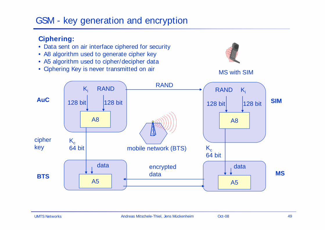
GSM - key generation and encryption
A8
RANDKi
128 bit 128 bit
Kc64 bit
A8
RAND Ki
128 bit 128 bit
SRES
RAND
encrypteddata
mobile network (BTS)
MS with SIM
AuC
BTS
SIM
A5
Kc64 bit
A5MS
data data
cipherkey
Ciphering:• Data sent on air interface ciphered for security• A8 algorithm used to generate cipher key• A5 algorithm used to cipher/decipher data• Ciphering Key is never transmitted on air
UMTS Networks 50Andreas Mitschele-Thiel, Jens Mückenheim Oct-08
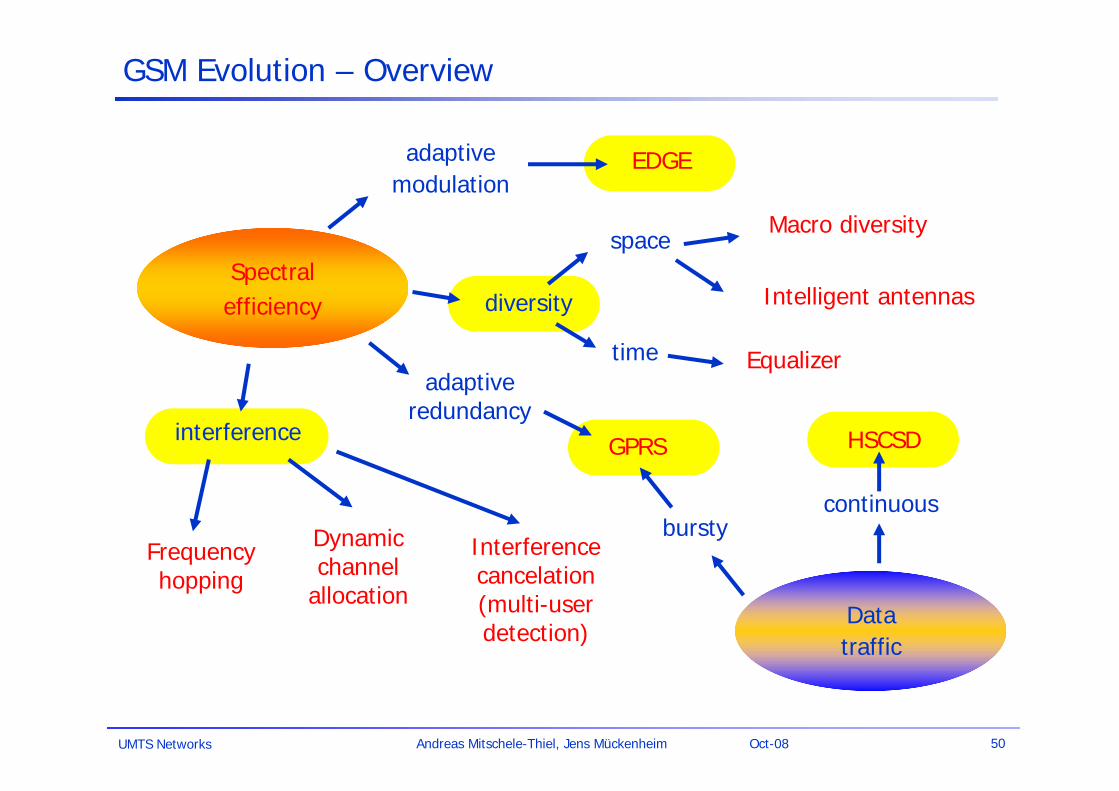
GSM Evolution – Overview
Spectralefficiency
Datatraffic
adaptivemodulation
EDGE
diversity
space
time
Macro diversity
Intelligent antennas
Equalizeradaptive
redundancyinterference
Frequencyhopping
Dynamicchannel
allocation
GPRS
bursty
HSCSD
continuous
Interference cancelation (multi-user detection)
UMTS Networks 51Andreas Mitschele-Thiel, Jens Mückenheim Oct-08
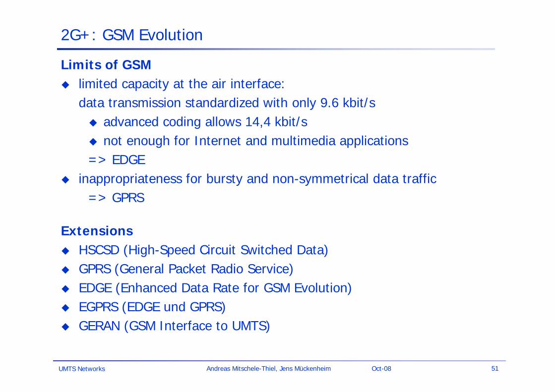
2G+: GSM Evolution
Limits of GSM limited capacity at the air interface:
data transmission standardized with only 9.6 kbit/s advanced coding allows 14,4 kbit/s not enough for Internet and multimedia applications => EDGE
inappropriateness for bursty and non-symmetrical data traffic => GPRS
Extensions HSCSD (High-Speed Circuit Switched Data) GPRS (General Packet Radio Service) EDGE (Enhanced Data Rate for GSM Evolution) EGPRS (EDGE und GPRS) GERAN (GSM Interface to UMTS)
UMTS Networks 52Andreas Mitschele-Thiel, Jens Mückenheim Oct-08
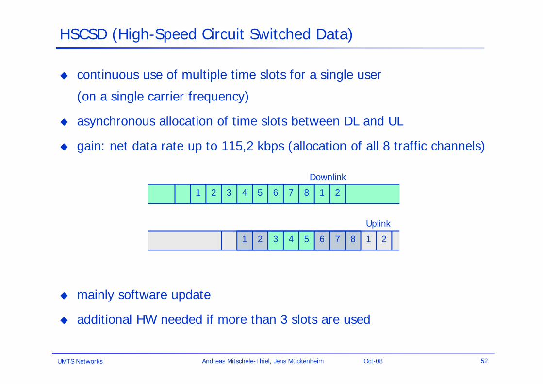
HSCSD (High-Speed Circuit Switched Data)
continuous use of multiple time slots for a single user
(on a single carrier frequency)
asynchronous allocation of time slots between DL and UL
gain: net data rate up to 115,2 kbps (allocation of all 8 traffic channels)
mainly software update
additional HW needed if more than 3 slots are used
Uplink
Downlink
71 2 3 84 5 6 1 2
71 2 3 84 5 6 1 2
UMTS Networks 53Andreas Mitschele-Thiel, Jens Mückenheim Oct-08
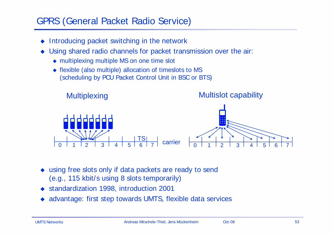
GPRS (General Packet Radio Service)
Introducing packet switching in the network Using shared radio channels for packet transmission over the air:
multiplexing multiple MS on one time slot flexible (also multiple) allocation of timeslots to MS
(scheduling by PCU Packet Control Unit in BSC or BTS)
using free slots only if data packets are ready to send (e.g., 115 kbit/s using 8 slots temporarily)
standardization 1998, introduction 2001 advantage: first step towards UMTS, flexible data services
carrierTS0 1 2 3 4 5 6 7 0 1 2 3 4 5 6 7
Multiplexing Multislot capability
UMTS Networks 54Andreas Mitschele-Thiel, Jens Mückenheim Oct-08
Multiplexing and multislot allocation
GPRS network elements GSN (GPRS Support Nodes): GGSN and SGSN GGSN (Gateway GSN)
interworking unit between GPRS and PDN (Packet Data Network) SGSN (Serving GSN)
supports the MS (location, billing, security) HLR (GPRS Register – GR)
maintains location and security information

UMTS Networks 55Andreas Mitschele-Thiel, Jens Mückenheim Oct-08
connection-orientedpacket switched core
GPRS architecture and interfaces
MS BSS GGSNSGSN
MSC
Um
EIR
HLR/GR
VLR
PDN /Internet
Gb Gn Gi
SGSN
Gn
UMTS Networks 56Andreas Mitschele-Thiel, Jens Mückenheim Oct-08
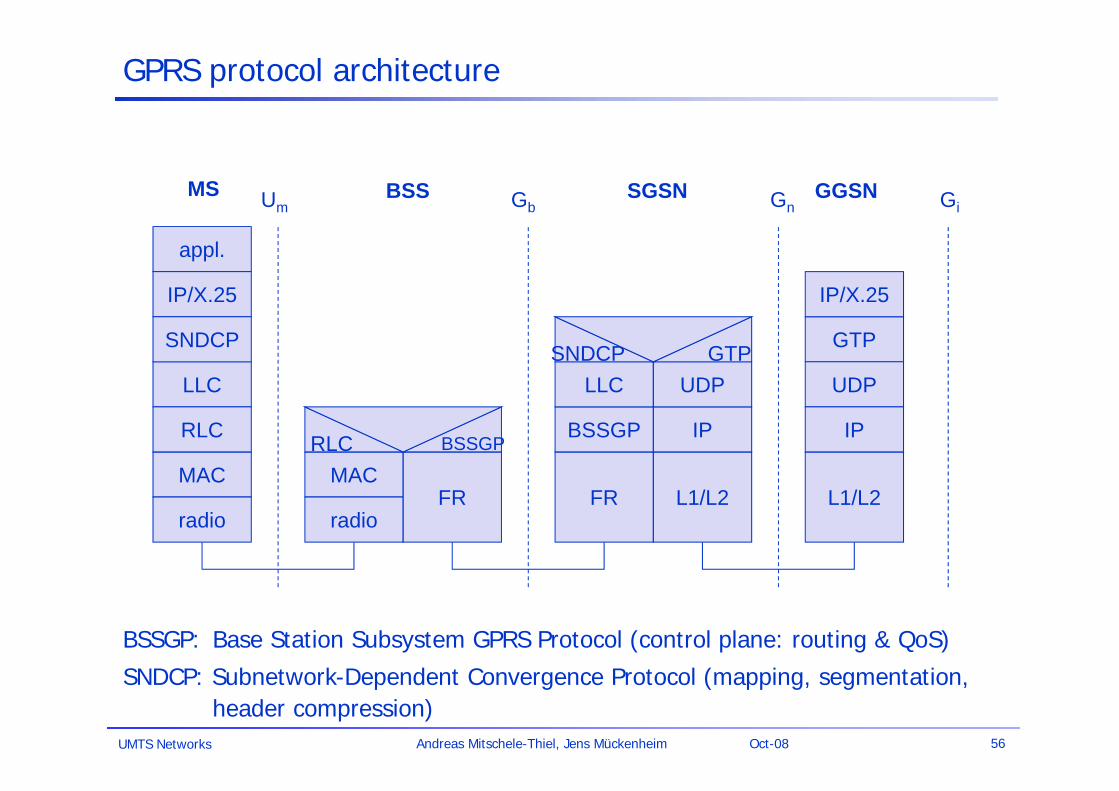
GPRS protocol architecture
appl.
IP/X.25
LLC
GTP
MAC
radio
MAC
radioFR
RLC BSSGP
IP/X.25
FR
Um Gb Gn
L1/L2 L1/L2
MS BSS SGSN GGSN
UDP
Gi
SNDCP
RLC BSSGP IP IP
LLC UDPSNDCP GTP
BSSGP: Base Station Subsystem GPRS Protocol (control plane: routing & QoS)
SNDCP: Subnetwork-Dependent Convergence Protocol (mapping, segmentation, header compression)
UMTS Networks 57Andreas Mitschele-Thiel, Jens Mückenheim Oct-08
GPRS services
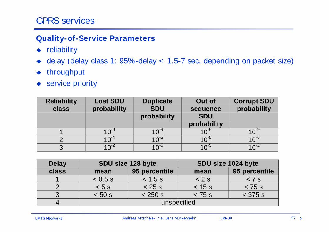
Quality-of-Service Parameters reliability delay (delay class 1: 95%-delay < 1.5-7 sec. depending on packet size) throughput service priority
Reliabilityclass
Lost SDUprobability
DuplicateSDU
probability
Out ofsequence
SDUprobability
Corrupt SDUprobability
1 10-9 10-9 10-9 10-9
2 10-4 10-5 10-5 10-6
3 10-2 10-5 10-5 10-2
Delay SDU size 128 byte SDU size 1024 byteclass mean 95 percentile mean 95 percentile
1 < 0.5 s < 1.5 s < 2 s < 7 s2 < 5 s < 25 s < 15 s < 75 s3 < 50 s < 250 s < 75 s < 375 s4 unspecified
o

UMTS Networks 58Andreas Mitschele-Thiel, Jens Mückenheim Oct-08
GPRS services
End-to-end packet switched traffic (peak channel rates) 28 kbps (full use of 3 time slots, CS-1: FEC) 171.2 kbps (full use of 8 time slots, CS-4: no FEC)
Average aggregate throughput of a cell (Source: H. Menkes, WirelessWeb, Aug. 2002)
95 kbps (for both up and downlink)Assumptions: 4/12 reuse, realistic RF conditions, random traffic Worse figures for individual TCP traffic
Adaptive Coding Schemes (adaptive Forward Error Control – FEC) CS 1: 9.05 Kbps/slot CS 2: 13.4 Kbps/slot CS 3: 15.6 Kbps/slot CS 4: 21.4 Kbps/slot (no Forward Error Correction)
Problems and limits IP-based network => high latency, no guarantees Limited data rate: 27 kbps (3 slot/CS-1) - 64.2 kbps (3 slot/CS-4) Latency/flow control problems with TCP

UMTS Networks 59Andreas Mitschele-Thiel, Jens Mückenheim Oct-08
EDGE (Enhanced Data Rates for GSM Evolution)
Enhanced spectral efficiency depends on: Size of frequency band Duration of usage Level of interference with others (power)
EDGE Technology: EDGE can carry data speeds up to 236.8 kbit/s for 4
timeslots (theoretical maximum is 473.6 kbit/s for 8 timeslots)
Adaptation of modulation depending on quality of radio path GMSK (GSM standard – 1 bit per symbol) 8-PSK (3 bits per symbol)
Adaptation of coding scheme depending on quality of radio path (9 coding schemes)
Gain: data rate (gross) up to 69,2kbps (compare to 22.8kbps for GSM)
complex extension of GSM!
NodeB
UE 1
UE 2
Near-far problem
UMTS Networks 60Andreas Mitschele-Thiel, Jens Mückenheim Oct-08
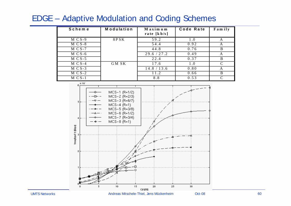
EDGE – Adaptive Modulation and Coding SchemesS c h e m e M o d u la t i o n M a x i m u m
ra te [k b /s ]C o d e R a te F a m i l y
M C S -9 5 9 .2 1 .0 AM C S -8 5 4 .4 0 .9 2 AM C S -7 4 4 .8 0 .7 6 BM C S -6 2 9 .6 / 2 7 .2 0 .4 9 AM C S -5
8 P S K
2 2 .4 0 .3 7 BM C S -4 1 7 .6 1 .0 CM C S -3 1 4 .8 / 1 3 .6 0 .8 0 AM C S -2 1 1 .2 0 .6 6 BM C S -1
G M S K
8 .8 0 .5 3 C
UMTS Networks 61Andreas Mitschele-Thiel, Jens Mückenheim Oct-08
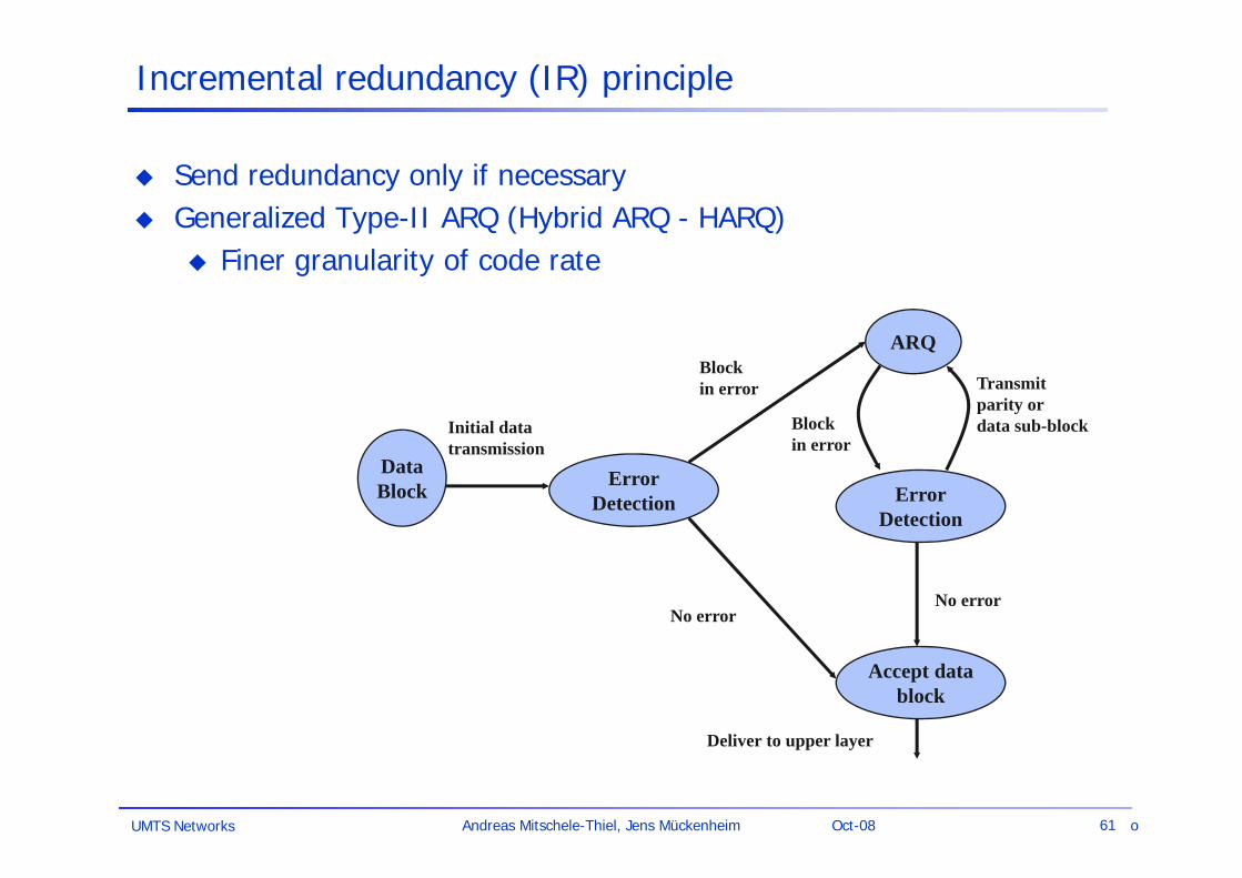
Incremental redundancy (IR) principle
Send redundancy only if necessary Generalized Type-II ARQ (Hybrid ARQ - HARQ)
Finer granularity of code rate
DataBlock Error
Detection
ARQ
ErrorDetection
Accept datablock
Block in error
No error
Initial datatransmission
Block in error
Transmitparity ordata sub-block
No error
Deliver to upper layer
o
UMTS Networks 62Andreas Mitschele-Thiel, Jens Mückenheim Oct-08
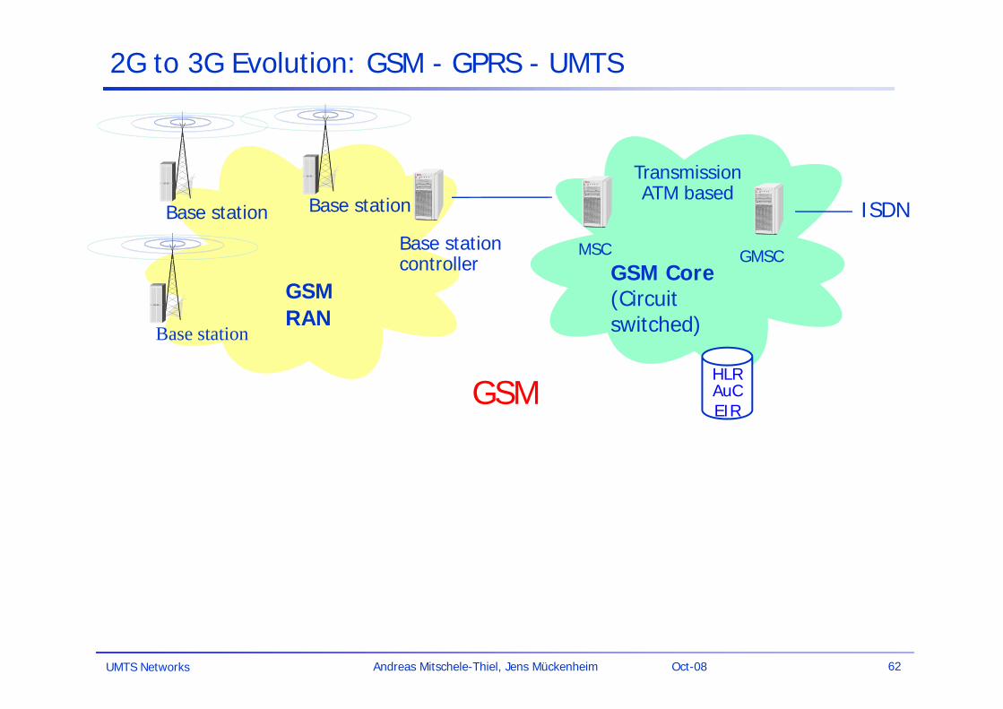
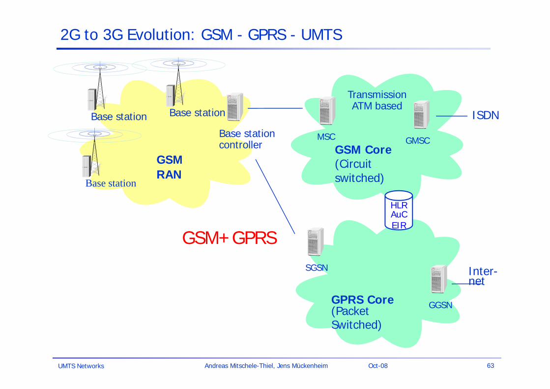
2G to 3G Evolution: GSM - GPRS - UMTS
GSMRAN
Base station
Base stationcontroller
Base station
Base station
MSC
ISDN
GSM Core (Circuit switched)
HLRAuCEIR
GMSC
TransmissionATM based
GSM
UMTS Networks 63Andreas Mitschele-Thiel, Jens Mückenheim Oct-08
2G to 3G Evolution: GSM - GPRS - UMTS
GPRS Core (PacketSwitched)
SGSN
GGSN
Inter-net
GSMRAN
Base station
Base stationcontroller
Base station
Base station
MSC
ISDN
GSM Core (Circuit switched)
HLRAuCEIR
GMSC
TransmissionATM based
GSM+GPRS
UMTS Networks 64Andreas Mitschele-Thiel, Jens Mückenheim Oct-08
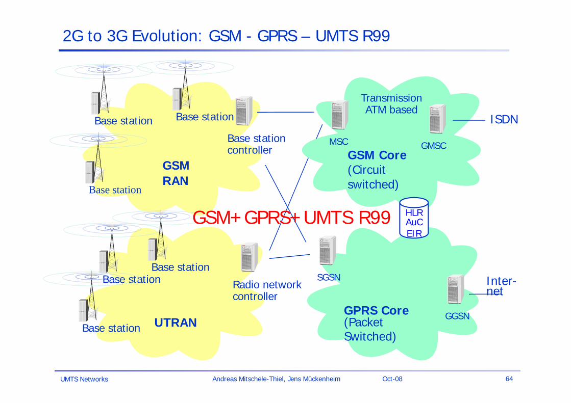
2G to 3G Evolution: GSM - GPRS – UMTS R99
GPRS Core (PacketSwitched)
SGSN
GGSN
Inter-net
GSMRAN
Base station
Base stationcontroller
Base station
Base station
UTRAN
Radio networkcontroller
Base station Base station
Base station
MSC
ISDN
GSM Core (Circuit switched)
HLRAuCEIR
GMSC
TransmissionATM based
GSM+GPRS+UMTS R99
UMTS Networks 65Andreas Mitschele-Thiel, Jens Mückenheim Oct-08
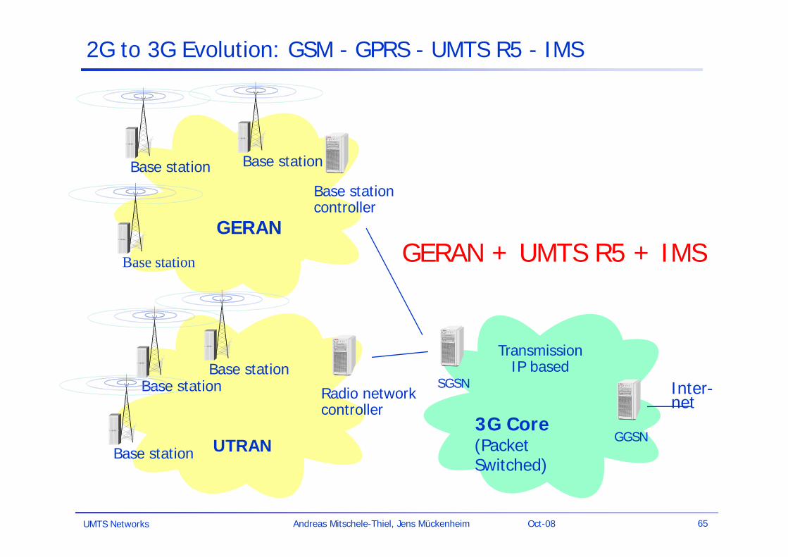
2G to 3G Evolution: GSM - GPRS - UMTS R5 - IMS
GPRS Core (PacketSwitched)
SGSN
GGSN
Inter-net
GSMRAN
Base station
Base stationcontroller
Base station
Base station
UTRAN
Radio networkcontroller
Base station Base station
Base station
TransmissionIP based
3G Core
GERANGERAN + UMTS R5 + IMS
UMTS Networks 66Andreas Mitschele-Thiel, Jens Mückenheim Oct-08
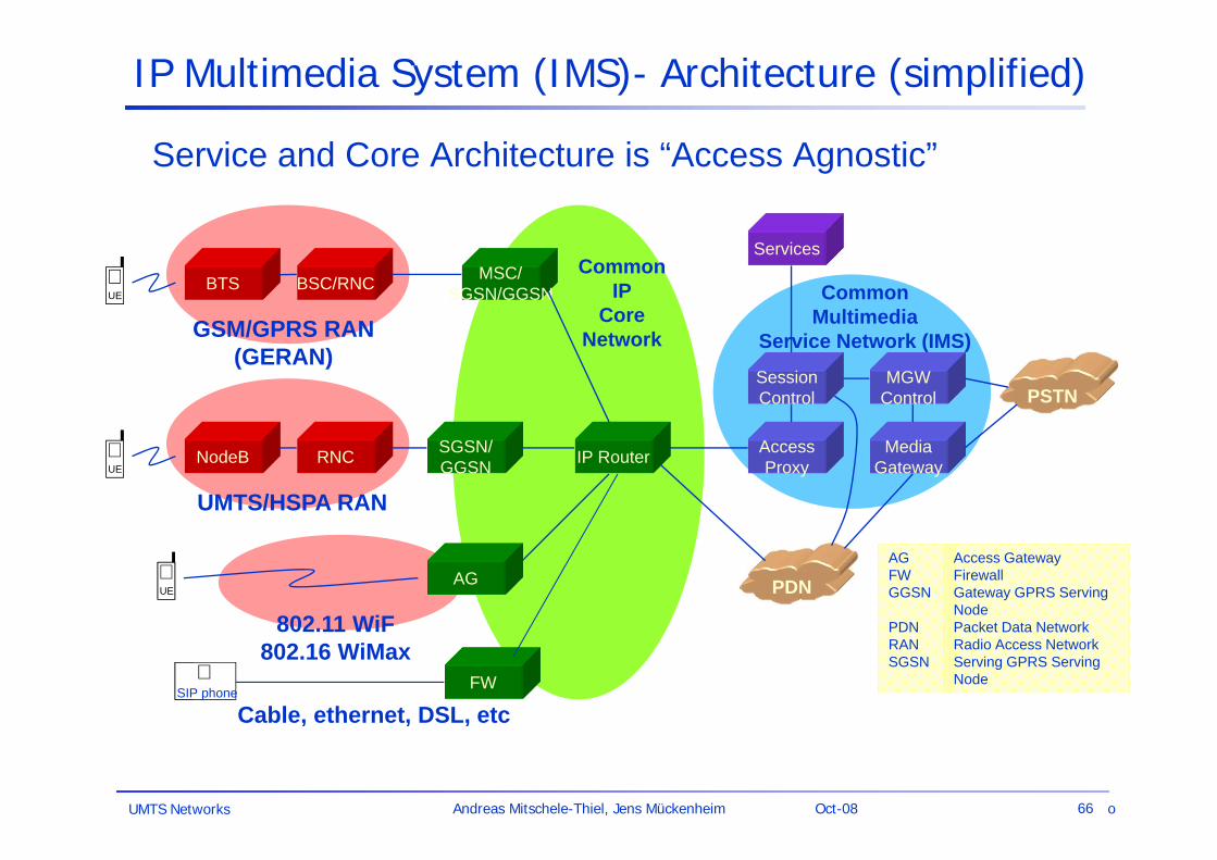
IP Multimedia System (IMS)- Architecture (simplified)
PSTN
PDN
MediaGateway
MGWControl
SessionControl
Services
CommonMultimedia
Service Network (IMS)
AccessProxy
BTS BSC/RNC MSC/SGSN/GGSNUEUE
GSM/GPRS RAN(GERAN)
CommonIP
CoreNetwork
NodeB RNC SGSN/GGSN IP Router
UEUE
UMTS/HSPA RAN
UEUE
802.11 WiF802.16 WiMax
AG
Service and Core Architecture is “Access Agnostic”
AGFW GGSN
PDNRANSGSN
Access GatewayFirewallGateway GPRS Serving NodePacket Data NetworkRadio Access NetworkServing GPRS Serving NodeFWUESIP phone
Cable, ethernet, DSL, etc
o


