Weishaupt Monarch oil burnersSizes 1 and 3
1/2002 GB

2
Description
Weishaupt Monarch oil burners are ofthe fully automatic pressure atomisingtype. Their design has been carefullyconsidered down to the smallestdetail and has been proved successfulover and over again. They meet all thedemands for safety, reliability and lowcost servicing. Weishaupt oil burnersare type tested to EN 267.
The burners are distinguished by avariety of interesting features:
■ Range of application 6 - 65 kg/h (71 - 775 kW)
■ Automatic sequence of operations■ Stable fan characteristics – good
combustion results■ Air regulation on pressure side■ Air damper closed on burner shut-
down ■ Quiet operation■ Complete pre-wired integral switch-
gear■ Hinged burner casing■ Combustion head can be withdrawn
when the burner is hinged open■ The design of the burner makes
installation, adjustment and servicingeasy
ConstructionAll the components are assembled in oneunit. The motor drives the fan and the fuelpump. All the equipment used for theregulation of fuel and air is clearlyarranged and easily accessible. Theburners can be hinged to the left or right,which simplifies service work on thecombustion head, diffuser, nozzles andignition electrodes.
ApplicationThe burners can be used on hot waterboilers, steam boilers, air heaters and forcertain heating processes. The burnersare used in particular on modern, highrated boilers, as they are capable ofovercoming high combustion chamberpressures. RL burners are preferablyused where there is a continuallychanging heat demand.
FuelsDistillate oil and medium oil to DIN 51 603 can be fired.Viscosity:Types Monarch L and RL -< 6 mm2/s at 20°CType Monarch M - ≤ 75 mm2/s at 50°C
RegulationOn L and M type burners, the regulationof oil and air takes place as follows:■ two stage, nozzle head with two
nozzles and a motor controlled,quickly opening air damper.
■ three stage, with three nozzles and amotor controlled, slowly opening airdamper.
The RL burner alters its capacity slowly(sliding). Fuel and air are controlled incompound. The burner can, dependingon the controller and servomotor, beeither:■ sliding two stage (20 s running time)
or■ modulating (42 s running time)
With sliding two stage regulation, thepartial and full load positions are fixedwithin the burner operating range. Theburner slides to one position or the other,depending on the appliance demand,and there are no rapid changes of fuelthroughput .
By fitting a suitable controller into thecontrol panel, the burner can be alteredto modulating operation. Modulatingburners operate at any point within thecapacity range, depending on the heatdemand.
On sliding two stage burners andmodulating burners, the slow capacityalteration ensures a particularly goodmatching to the heating appliance.
Flame supervisionThe burner controller automaticallysequences the operations and monitorsthe flame optically via the flame sensor.
The controller is mounted on the burneron all standard L and M burners, but canbe supplied loose if requested. Togetherwith the control panel, each burner formsone complete unit. On the RL burner, theburner controller is supplied loose forfitting into the control panel.
There is no interference with radio andtelevision reception, as radio interferencecreated during ignition is below thepermitted limits specified by the relevantEMC standards and regulations.
Quiet operationWeishaupt burners operate quietly. All airhandling burner parts have beenaerodynamically designed, the fuel / airmixing noise is reduced to a minimumand rotors and fan wheels aredynamically balanced. For installationswhere special emphasis is placed onburners with low noise levels, soundabsorbers which reduce burner noise byapproximately 70% are available (pleaseask for details).
Oil temperature regulationResidual oil burners are fitted with an oilpreheater. The oil is quickly heated to therequired atomising temperature, due tothe large heat exchange surfacecombined with a relatively small oilvolume. Fast, even heat distributionprevents local overheating andcarbonisation of the oil.
Heated nozzle head and nozzlerecirculation system on residual oilburnersAll residual oil burners are fitted with aheated nozzle head system. After the oiltemperature in the nozzle head has beenreached, the burner starts by means of arelease thermostat. During prepurge,heated oil flows through the nozzle headand oil line system. This ensures thatevenly heated oil is available for flameestablishment.

3
Integral switchgear (distillate oil burner) Monarch M residual oil burner, preheater side
Monarch RL distillate oil burner, compound regulator side
Monarch RL distillate oil burner, regulating drive
Pressure side air regulation
Combustion head removable from behind
Monarch L distillate oil burner, two stage

4
Included in deliveryIndustrial version
Included in burner delivery L1Z-B L3Z-A (LN) L1T-B M1Z-B RL3-A L3T-A M3Z-A
Burner casing with integral air inlet, hinged flange, hinge interlock switch, flange gasket, ● ● ● ● ●Weishaupt burner motor, fan, pump, oil hoses, nozzle assembly, combustion head, ignitiontransformer, ignition cables, ignition electrodes, fixing screws, air damper on fan pressure side.
Oil solenoid valve(s) ● ● ● ● ●
Additional safety valve(s) ● ● ● ● ●and oil pressure switch (on burners >30 kg/h) – – – ● ●
Nozzles(s) ● ● ● ● ●
Burner controller with flame sensor– Type LOA for burners <30 kg/h ● ● – ● –– Type LAL for burners > 30 kg/h ● ● ● ● ●– Type LFL 1.322 with QRA2 – ● – – –
Terminal strip or ● ● ● ● ●Integral switchgear ● ● ● ● –
Servomotor for air regulation ● ● ● ● –
Servomotor for oil / air regulation with regulating cam (sliding two stage burners – – – – ●type SQM 10.15562, 20 s running time; modulating burners type SQM 10.16562, 42 s running time), oil regulator, spill type nozzle
Oil preheater, heated nozzle head and nozzle recirculation system, – – – ● –filter
Parts supplied with integralswitchgearThe integral switchgear version includesall the parts required for operation.1 stage 1 control switch with indicating
lamp1 stage 2 control switch with indicating
lamp1 contactor (motor)1 overload relay
(three phase burners only)
1 contactor for oil preheater on burnertype M1Z-B (2 on burner type M3Z-A)Hours counters can be fitted onrequest at extra cost.
Industrial executionWhere required, a special industrialversion of burner sizes 1 and 3 can besupplied. This version is suitable forprocess applications, e.g. whereoperating conditions are severe. Theseburners differ from the standard versionas follows:
1. Black painted aluminium cover overthe terminal box and air regulator.
2. Waterproof (to IP 65) safety valve andstage 1 and 2 solenoid valves.
3. All external connection cables inconduit.
4. A separate control panel is providedfor the burner switchgear.
The additional prices are shown on page12 (special equipment).
Only possible for burners without integral switchgear
Explanation of type designationR L 3 Z – A version ZMD
E = single phase a.c.D = three phase a.c.
Type of regulationZM = sliding two stage
Code for burner seriesZ = two stage, T = three stage
SizeL = distillate oil EL, M = residual oil M
R = variably regulated burner
Monarch L distillate oil burner, two stage industrial version Aluminium cover
(Standard execution burner)
5
Model overviewTypes of regulation
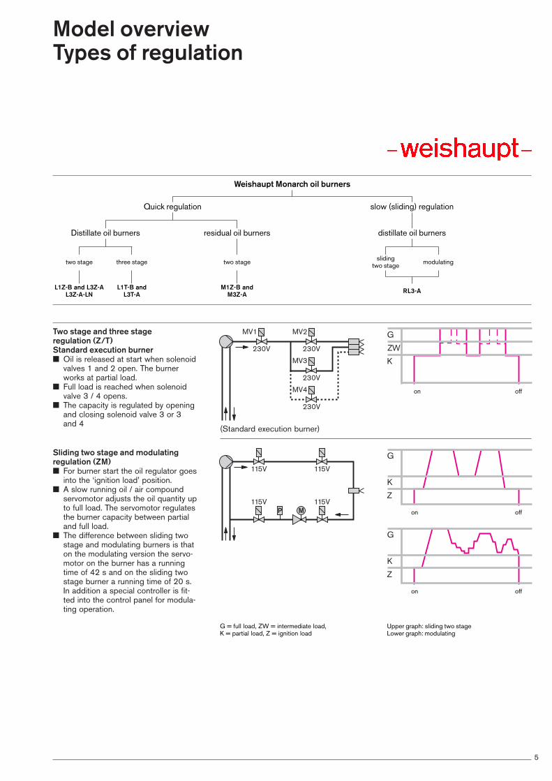
Two stage and three stage regulation (Z/T) Standard execution burner■ Oil is released at start when solenoid
valves 1 and 2 open. The burnerworks at partial load.
■ Full load is reached when solenoidvalve 3 / 4 opens.
■ The capacity is regulated by openingand closing solenoid valve 3 or 3 and 4
Sliding two stage and modulatingregulation (ZM)■ For burner start the oil regulator goes
into the ‘ignition load’ position.■ A slow running oil / air compound
servomotor adjusts the oil quantity upto full load. The servomotor regulatesthe burner capacity between partialand full load.
■ The difference between sliding twostage and modulating burners is thaton the modulating version the servo-motor on the burner has a runningtime of 42 s and on the sliding twostage burner a running time of 20 s.In addition a special controller is fit-ted into the control panel for modula-ting operation.
230V
230V
230V
230V
MV1 MV2
MV3
MV4
115V 115V
115V115VP M
G
K
Z
G
K
Z
Upper graph: sliding two stageLower graph: modulating
G = full load, ZW = intermediate load, K = partial load, Z = ignition load
on
on
G
ZW
K
on off
off
off
Distillate oil burners
two stage
L1Z-B and L3Z-AL3Z-A-LN
L1T-B and L3T-A
M1Z-B and M3Z-A RL3-A
three stage two stage sliding two stage modulating
residual oil burners distillate oil burners
slow (sliding) regulationQuick regulation
Weishaupt Monarch oil burners

6
Size 1 burner selectionBurner rating / combustion chamber pressure
Burner type _______ L1Z-B and L1T-BVersion ____________________ E and DCombustion head type
L1Z-B_____ M1/5a-105Kx33L1T-B _____ M1/5a-105Kx36
Rating kg/h ________________ 6-29kW ______________ 70-345
Burner type _______ L1Z-B and L1T-BVersion ____________________ E and DCombustion head type
L1Z-B_____ M1/5a-100Kx33L1T-B _____ M1/5a-100Kx36
Rating kg/h _______________ 10-35kW _____________ 120-415
Burner type ________________ M1Z-BVersion ____________________ E and DCombustion head type _______________ M1/5a-105Kx33Rating kg/h ________________ 8-31
kW ______________ 90-345
8
6
4
2
0
-20 100 200 300 400 500kW
0 10 20 30 40kg/h [EL]
mbar
8
6
4
2
0
-20 100 200 300 400 500kW
0 10 20 30 40kg/h [EL]
mbar
8
6
4
2
0
-20 100 200 300 400 500kW
0 10 20 30 40kg/h [M]
mbar
7
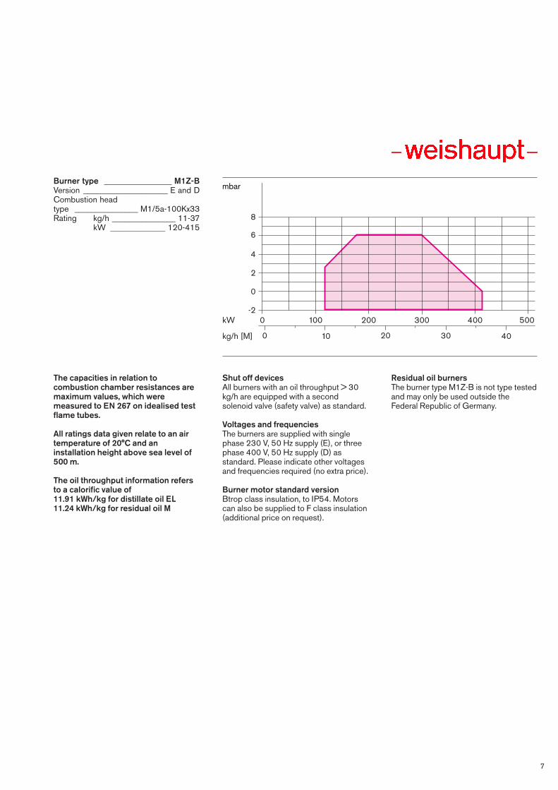
Burner type ________________ M1Z-BVersion ____________________ E and DCombustion head type _______________ M1/5a-100Kx33Rating kg/h _______________ 11-37
kW _____________ 120-415
The capacities in relation tocombustion chamber resistances aremaximum values, which weremeasured to EN 267 on idealised testflame tubes.
All ratings data given relate to an airtemperature of 20°C and aninstallation height above sea level of500 m.
The oil throughput information refersto a calorific value of 11.91 kWh/kg for distillate oil EL11.24 kWh/kg for residual oil M
Shut off devicesAll burners with an oil throughput > 30kg/h are equipped with a secondsolenoid valve (safety valve) as standard.
Voltages and frequenciesThe burners are supplied with singlephase 230 V, 50 Hz supply (E), or threephase 400 V, 50 Hz supply (D) asstandard. Please indicate other voltagesand frequencies required (no extra price).
Burner motor standard versionBtrop class insulation, to IP54. Motorscan also be supplied to F class insulation(additional price on request).
Residual oil burnersThe burner type M1Z-B is not type testedand may only be used outside theFederal Republic of Germany.
8
6
4
2
0
-20 100 200 300 400 500kW
0 10 20 30 40kg/h [M]
mbar

8
Size 3 burner selectionBurner rating / combustion chamber pressure
Burner type ____ L3Z-A, L3T-A, M3Z-AVersion L-Burner _________ E, D, E-C and D-CM-Burner _______________ D and D-CCombustion head type ________________ M2/1a-116x40Rating kg/h-distillate oil EL____ 10-40
kg/h-residual oil M __10.7-46.7kW _______________ 120-525
Burner type ____ L3Z-A, L3T-A, M3Z-AVersion L-Burner _________ E, D, E-C and D-CM-Burner _______________ D and D-CCombustion head type _________________ M5/2a-116x40Rating kg/h-distillate oil EL ____16-65
kg/h-residual oil M ___16.9-69kW _______________190-775
8
6
4
2
0
-20kW
0 10 20 30 40kg/h [EL]
0 10 20 30 40kg/h [M]
100 200 300 400 700 800500 600
50 60 70
50 60 70
mbar
8
6
4
2
0
-20kW
0 10 20 30 40kg/h [EL]
0 10 20 30 40kg/h [M]
100 200 300 400 700 800500 600
50 60 70
50 60 70
mbar

9
Burner type _________________ RL3-AVersion ______________ ZME and ZMDCombustion head type__ M2/1a-116x40Rating kg/h ________________10-44
kW ______________120-525
Burner type _________________ RL3-AVersion ______________ ZME and ZMDCombustion head type _ M5/2a-116x40Rating kg/h _______________ 16-65
kW _____________ 190-775
The capacities in relation tocombustion chamber resistances aremaximum values, which weremeasured to EN 267 on idealised testflame tubes.
All ratings data given relate to an airtemperature of 20°C and aninstallation height above sea level of500 m.
The oil throughput information refersto a calorific value of 11.91 kWh/kg for distillate oil EL11.24 kWh/kg for residual oil M
Shut off devicesAll burners with an oil throughput > 30 kg/h are equipped with a secondsolenoid valve (safety valve) as standard.
Voltages and frequenciesThe burners are supplied with singlephase 230 V, 50 Hz supply (E), or threephase 400 V, 50 Hz supply (D) asstandard. Please indicate other voltagesand frequencies required (no extra price).
Burner motor standard versionBtrop class insulation, to IP54. Motorscan also be supplied to F class insulation(additional price on request).
Residual oil burnersThe burner type M3Z-A is not type testedand may only be used outside theFederal Republic of Germany.
Modulating burnersThe modulating RL3-A burner is basedon the sliding two stage burner. Themodulating feature is obtained by fitting asuitable electrical controller into thepanel (for price see accessories list).
8
6
4
2
0
-20kW
0 10 20 30 40kg/h [EL]
100 200 300 400 700 800500 600
50 60 70
mbar
8
6
4
2
0
-20kW
0 10 20 30 40kg/h [EL]
100 200 300 400 700 800500 600
50 60 70
mbar

10
Order numbers, technical information
Description L1Z-B L1T-B L3Z-A L3Z-AVersion E / D➂ Version E / D➂ Version E / D➄ Version E-C / D-C
Order numbers - Version E or EC with integral switchgear ➀ 211 163 03 211 193 03 211 363 01 711 365 01Version E or EC without integral switchgear ➁ 211 163 04 211 193 04 211 363 02 711 365 02Version D or DC with integral switchgear ➀ 211 164 03 211 194 03 211 364 01 711 366 01Version D or DC without integral switchgear ➁ 211 164 04 211 194 04 211 364 02 711 366 02Version ZME without integral switchgear ➁ – – – –Version ZMD without integral switchgear ➁ – – – –
Version E Version E Version E Version E–CBurner motor 1Z230V, 50 Hz Type ECK07–2 ECK07–2 ECK08/90–2 ECK08/90–2Nominal capacity kW 0.25 0.25 0.76 0.76Nominal load at 230V A 2.3 2.3 6 6Motor pre-fuse A 10 10 16 16Speed rpm 2850 2850 2850 2850Capacitor µF 16 16 25 25
Version D Version D Version D Version D–CBurner motor 3Z230/400V, 50 Hz Type DK07/F-2 DK07/F-2 DK07/F-2 DK07/F-2Nominal capacity kW 0.76 0.76 0.76 0.76Nominal load at 230/400V A 3.6/2.1 3.6/2.1 3.6/2.1 3.6/2.1Motor pre-fuse A 6 6 6 6Speed rpm 2820 2820 2820 2820
Type test No. 5G547/95 5G548/95 5G549/95 5G549/95
Burner controller Type LOA 24.171 ➃ LAL2 LOA 24.171 ➃ LAL2
Servomotor Type –w– 1055/23 – W – 1055/80 –w– 1055/23 –w– 1055/23
Pump Type AE67 AE67 AE97 AE97
Fan galvanised galvanised galvanised galvanisedIgnition transformer V 2 x 5000 2 x 5000 2 x 5000 2 x 5000
Oil hoses DN 8 8 8 8Length / mm 1000 1000 1000 1000Connection 3/8” 3/8” 3/8” 3/8”
Oil preheater Type – – – –Heating capacity / kW – – – –
Weight kg (approx.) 29 29 40 40
➀ A separate control panel is required on installations to TRD 604, 72 hr (operation without continuous supervision). The integral switchgear is therefore omitted.
➁ On burners without integral switchgear, the burner controller is supplied loose. It can bemounted on the burner at extra cost (see page12). A terminal strip is provided in both cases.
➂ L1Z-B and L1T-B burners, versions E and D,can be used with this specification up to 30 kg/h. Over 30 kg/h the additional prices for “LAL 2.25 burner controller in lieu of LOA 24.171” and “Solenoid valve as additionalshut off device” apply (see special equipment,page 12).
➃ Flame monitoring with flame sensor QRB.
➄ L3Z-A burners, versions E and D, can be usedwith this specification up to 30 kg/h. Over 30 kg/h L3Z-A burners versions E-C or D-C should be used (see page 11). These burners are fitted with an LAL 2.25 burner controller and an additional safety solenoid valve as standard.
11
L3T-A L3Z-A-1LN RL3-A M1Z-B M3Z-A M3Z-AVersion E-C, D / D-C Version D-C Version ZME / ZMD Version E / D Version D Version D-C
711 395 01 – – – – – 711 395 02 – – 212 163 04 – – 711 396 01 211 364 23 – – 712 364 03 712 366 03711 396 02 211 364 24 – 212 164 04 712 364 04 712 366 04– – 711 373 02 – – – – – 711 374 02 – – –
Version E Version E–C Version ZME Version E – –ECK08/90–2 ECK08/90–2 ECK08/90–2 ECK07–2 – –0.76 0.76 0.76 0.25 – –6 6 6 2.3 – –16 16 16 10 – –2850 2850 2850 2850 – –25 25 25 16 – –
Version D–C Version D–C Version ZMD Version D Version D Version D–CDK07/F-2 DK07/F-2 DK07–2/2 DK07/F-2 DK07/F-2 DK07/F-20.76 0.76 0.76 0.76 0.76 0.763.6/2.1 3.6/2.1 3.6/2.1 3.6/2.1 3.6/2.1 3.6/2.16 6 6 6 6 62820 2820 2820 2820 2820 2820
5G549/95 5G862/98 5G552/95 – – –
LAL2 LFL1.322 with QRA2 LAL2 LOA 24.571 ➃ LOA 24.171 ➃ LAL2
-w- 1055/80 -w- 1055/80 SQM 10... –w– 1055/23 –w– 1055/23 –w– 1055/23
AE 97 AT 65 AJ6 E4 E4 E4
galvanised galvanised galvanised galvanised galvanised galvanised2 x 5000 2 x 5000 2 x 5000 2 x 5000 2 x 5000 2 x 5000
8 8 8 13 13 131000 1000 1000 500 u. 800 700 u. 1000 700 u. 10003/8” 3/8” 3/8” 1/2” 1/2” 1/2”
– – – EV1B EV2B EV2B– – – 1.8 4.5 4.5
40 40 47 36 55 55

12
Special equipment
Item Description L1… L3…No. M1… M3…
Order No. Order No.1 Hours counter in integral switchgear 1 x L…Z + T 210 000 69 210 000 69
2 x L…Z 210 000 70 210 000 70
2 x M…Z 210 000 70 210 000 70
2 Heating for pump E M…Z 110 004 74 110 004 74
3 Pressure gauge with isolating valve L…Z + T 110 006 63 110 006 63RL – 210 000 92
M…Z 110 008 82 110 008 82
4 Vacuum gauge with isolating valve L…Z + T 110 006 64 110 006 64RL – 110 006 64
M…Z 110 005 70 110 005 70
5 Potentiometer fitted in servomotor (ZM) RL 220 Ohm – 110 002 86RL 1000 Ohm – 110 003 03
6 Solenoid valve as additional shut off device ➀ M…Z 210 000 47 210 000 49
7 Solenoid vlave for post purge L…Z without E. 210 005 99 210 005 92to relieve pressure L…Z with E. 210 007 15 210 005 92
L…T without E. 210 006 20 210 007 07L…T with E – 210 007 07
RL – 210 000 52
M…Z 210 000 88 210 000 54
8 Magnetic clutch for post purge L…Z without E. 210 003 25 210 001 75to relieve pressure L…Z with E. 210 003 90 210 001 75
L…T without E. 210 004 92 210 005 19L…T with E. – 210 005 19
RL without E. – 210 001 44
M…Z without E. 210 003 26 210 003 01M…Z with E. 210 003 91 –
9 Combustion head extensions L1Z 100 mm 210 003 22 –(for standard execution burners) 200 mm 210 003 23 –
L1T 100 mm 210 004 76 –200 mm 210 004 77 –
M1Z 100 mm 210 003 30 –200 mm 210 003 31 –
L3Z 100 mm – 210 000 19200 mm – 210 000 21
L3T 100 mm – 210 004 79200 mm – 210 004 80
RL3 100 mm – 210 000 23200 mm – 210 000 25
M3Z 100 mm – 210 002 29200 mm – 210 002 30
10 Oil meter fitted L1Z 210 005 30 –L1T 210 004 86 –L3Z – 210 004 30L3T – 210 005 27
11 Oil hoses 1300 in lieu of 1000 mm lang L…Z + T 210 003 00 210 003 001000 mm, Gummi, beheizt M…Z 210 002 02 210 002 041300 mm, Gummi, beheizt M…Z 210 002 03 210 002 05
12 Burner controller LAL 2.25 in lieu of LOA 24.171 L…Z Exec. E 210 006 07 –(in combination with LAL 2.25 in lieu of LOA 24.171 L…Z Exec. D 210 002 62 –integral switchgear) LAL 2.25 in lieu of LOA 24.171 M…Z Exec. D 210 006 05 –
LOA 44.252 in lieu of LOA24.171➁ L…Z Exec. E 210 006 10 210 006 10➁LOA 44.252 in lieu of LOA24.171➁ L…Z Exec. D 210 002 52 210 002 52➁LOA 44.252 in lieu of LOA24.171➁ M…Z Exec. D – 210 002 52➁
LOK 16… in lieu of LOA… resp. LALL…Z Exec. E 210 006 11 210 006 18LOK 16… in lieu of LOA… resp. LALL…Z Exec. D 210 003 98 210 003 99
13 Bunrer controller LAL 2.25 in lieu of LOA 24.171 L…Z Exec. E + D 210 002 54 210 002 54(loose, for fitting into LOA 44.252 in lieu of LOA 24.171L…Z Exec. E 210 006 10 210 006 10control panel) LOA 44.252 in lieu of LOA 24.171L…Z Exec. D 210 002 52 210 002 52
LOA 44.252 in lieu of LOA 24.171M…Z Exec. D – 210 002 52
LOK 16… in lieu of LOA… resp. LALL…Z Exec. E + D 210 004 03 210 003 87LOK 16… in lieu of LOA… resp. LALL…Z Exec. E-C + D-C – 210 003 88LOK 16… in lieu of LOA… resp. LALRL… – 210 003 88
LGK16.322 L3Z-A-1LN – 210 005 93
14 Air intake flange RL… Exec. ZME – 210 003 97RL… Exec. ZMD – 210 003 35
15 Intake flange for connection of air duct. 210 000 67 210 000 67
16 Type of protection IP54/Industrial version L…Z 210 003 19 210 002 47L…T 210 006 02 210 006 03RL… – 210 004 17M…Z 210 006 04 210 003 77
Price reductions17 Oil preheater EV2A in lieu of EV2B M…Z Exec. D m. E. – 210 004 68
EV2A in lieu of EV2B M…Z Exec. D o. E. – 210 000 85EV2A in lieu of EV2B M…Z Exec. D-C m. E. – 210 004 69
➀ The additional price applies only to burners withoil throughputs up to 30 kg/h. For burners > 30 kg/h (version C) this solenoid valve is fittedas standard.
➁ Additional price applies to burners L3Z-A / M3Z-A.
Burners supplied to TRD 604, 24 hr / 72 hrSee technical leaflet, print No. 863.

230V
230V
1 143
7 8
115V
115V
230V
230VP
1 143
7 8
5
5a 9
P M
115V 115V
115V 115V
1 135
10 6a95a
644
230V
4
230V
230V
230V
1 12
4
44
230V 230V
230V
1 12
13
Burner fuel systems
1 Pump without inbuilt solenoid valve2 Pump with two inbuilt solenoid valves3 Oil preheater4 Normally closed solenoid valve 4a Normally open solenoid valve5 Normally closed solenoid valve (1st
shut off device in supply line 115 V,electrically connected in series)
5a Normally closed solenoid valve (1stshut off device in return line 115 V,electrically connected in series -fitted against direction of flow)
6 Normally closed solenoid valve (2nd shut off device in supply line115 V, electrically connected inseries)
6a Normally closed solenoid valve (2nd shut off device in return line 115 V, electrically connected in series - fitted against direction offlow)
7 Normally open solenoid valve (stage 1)
8 Normally closed solenoid valve (stage 2)
9 Pressure switch in return10 Oil regulator
11 Nozzle head with one nozzle, withoutshut off device
12 Nozzle head with two / three nozzles,without shut off device
13 Nozzle head R, without integral shutoff device
14 Nozzle head M, with integral shut offdevice
Monarch L1Z-B and L3Z-A burners Monarch L1T-B and L3T-A burners Monarch RL3-A sliding two stage andmodulating burner without shut offdevice
Monarch M1Z-B and M3Z-A burners < 30 kg/h
Monarch M1Z-B and M3Z-A burners > 30 kg/h

14
Dimensions
Monarch L and M Monarch RL
Size1 and 3
Size 3
Monarch L and M, size 1 and 3
Size Dimensions in mmh1 h2 h4 h5 h6 d1 d2 d3 d4 d5 d6 ➁ b1 b2 b3 ➀
1 388 150 290 420 195 M8 135 160–170 120 161/175➀ 128 526/507➀ 153 257/239➀3 435 170 325 460 220 M10 165 186 130/150➁ 161/175➀ 140/160➁ 592/533➀ 153 312/253➀
b4 b6 b7 l1 l2 l3 l4 ➁ l5 l6 l7 r1 r2
1 248 195 210 32 80 8 122 195 168 538 555➀ 6003 280 220 218 47 100 8 124/134➁ 198 188 645 665/650➀ 675
Monarch RL, Size 3
Size Dimensions in mmh1 h2 h3 h4 h6 d1 d2 d3 d4 d5 d6 b1 b2 b3 ➀
3 435 170 150 325 220 M10 165 186 130/150➁ 161/175➀ 140/160➁ 612/553➀ 153 312/253➀
b4 b5 b6 b7 l1 l2 l3 l4 l5 l6 l7 l8 r1 r2
3 280 385 220 218 47 100 8 124/134➁ 198 188 645 220 665/650➀ 650
➀ For version E/version D ➁ For combustion head M2/1a, M5/2a

15
Weishaupt control panelsand MCR technology
Weishaupt control panels for• two stage burners• three stage burners• sliding two stage burners
and modulating burners
The basic control panels contain all burner controls, that means all inbuiltswitchgear necessary for the operationof a burner.
DescriptionWeishaupt control panels conform toapplicable national/international standards.
Switching includes• Power supply• Burner control• Fan control• Start-up/regulation• Door mounted switches• Door mounted indicating lamps
Individual customer requirements can bemet at any time.
Weishaupt MCR technology for• Boiler installations• Thermal process equipment• Ships execution• Building management systems
Together with ist core business of burners and heating systems,Weishaupt are able to offer complexcontrol technology up to BMS level withSPS and DDC systems.
From planning to handover, tailor madesolutions are available from one supplier.

Max Weishaupt GmbH, D - 88475 SchwendiTel.: (07353) 830, Fax.: (07353) 83358Print No. 83002702, July 2002Printed in Germany. All rights reserved.
Weishaupt (U.K.) Ltd.Abbey House, 18-24 Stoke Road, SloughBerkshire SL2 5AGTel.: (01753) 722 085/086, Fax.: (01753) 722 087
Weishaupt (U.K.) Ltd.Neachells Lane, WillenhallWest Midlands, WV13 3RGTel. (01902) 60 98 41, Fax (01902) 63 33 43
Product and customer service-the complete Weishaupt range
Regular maintenance reduces heatingcosts and environmental pollution. Onlya properly adfusted burner can saveenegy end be environmentally friendly.Behind each Weishaupt customer service organisation. The outstandingefforts made in maintenance and servicejustify the enormous trust places inWeishaupt’s burners, for at Weishauptproduct and customer service belongtogether.
Weishaupt customer service is there foryou all year round. Whenever you needhelp, be it the supply of spare parts,technical advice or a site visit. We arethere when you need us.


![Information on ultra-low NO gas burners · NO x emissions below 30 mg/kWh: 4LN-version Weishaupt monarch® burners 2 120 160 140 0 25 100 80 60 0 40 20 50 75 100 Burner rating [%]](https://cdn.vdocuments.us/doc/165x107/60271967503721117a210920/information-on-ultra-low-no-gas-burners-no-x-emissions-below-30-mgkwh-4ln-version.jpg)

