Download - 27 Apr ‘06 1 Integrated Shipbuilding Environment (ISE) ISE4 Project Demonstration April 27, 2006

27 Apr ‘06 1
Integrated Shipbuilding Environment (ISE)
ISE4 Project
Demonstration
April 27, 2006

27 Apr ‘06 2
ISE4 Participants

27 Apr ‘06 3
Presentation Agenda
• Interoperability Demo Scenario• Ship Arrangements Exchanges using AP215 and AP216
– Initial Design in TRIBON
– Transfer from TRIBON to LEAPS
– Modifications in FORAN
– Transfer from FORAN to LEAPS (and ISDP)
– Transfer from ISDP to Intelliship
• Electrical Demonstration using AP212• Engineering Analysis Exchanges using AP218 and AP209• Steel Processing Exchanges using AP218

27 Apr ‘06 4
Interoperability Demo Scenario
• During the demonstrations you are about to witness, we will be exchanging product model data from several disciplines between multiple computer systems
• The scenarios are not necessarily meant to be realistic, but more to convey the types of exchanges and requirements that can be satisfied by the tools developed in the ISE Project
• Data to be exchanged will include product model data used for Ship Arrangements, Electrical, Engineering Analysis, and Steel Processing
• The data will be representative of product models that could be exchanged at any phase of the Life Cycle, from Concept Design through Detail Design through Manufacturing, or continuing through Repair and Overhaul

27 Apr ‘06 5
Description of Exchange Scenarios• The models exchanged represent the TWR841
– Torpedo Weapons Retriever ship with data “Approved for Public Release – Distribution Unlimited”
– Product Models will capture TWR Compartmentation and details of the TWR Engine Room
– These transfers simulate a situation where STEP is in place to enable Shipyards to interoperate smoothly
• Ship Arrangements exchanges represent – Exchanges to go from Concept Design to Detail Design at two different Shipyards– Models developed will be analyzed by Customer and changes will be suggested– Partnering Shipyards will complete the Design and feed data to other applications for
analysis, manufacturing, repair, and lifecycle support
• Electrical Analysis is done on TWR systems during Preliminary Design
• New requirements (such as a request from an outside agency, e.g. Homeland Security) can necessitate model transfer to additional software packages for Engineering Analysis
• Steel Processing scenario shows how design data for a plate can be modified in STEP before being sent to two possible construction yards with different requirements (NGSS and EB)

27 Apr ‘06 6
Lifecycle Phases for Demo Scenario
Evolving Ship Design from Concept to Maturity
Initial Design Detail Design Manufacturing Lifecycle Support
Time

27 Apr ‘06 7
Demo Scenarios for the Four ISE4 Tasks
Four Tasks and Demonstrations
Initial Design Detail Design Manufacturing Lifecycle Support
Engineering FEA Analysis
Concept & Preliminary Design Stage
DetailDesign Stage
Steel Processing
Electrical
Arrangements

27 Apr ‘06 8
Different Representations for Data• Part 21 vs. Part 28
– Part 21 is the traditional STEP physical file format– Part 28 is an XML representation of STEP data
• ARM vs. AIM– ARM (Application Reference Model) objects are in application
area terminology• e.g. “Ship” or “Plate”
– AIM (Application Interpreted Model) objects are in generic terminology
• e.g. “Product” or “Product Representation”
• ISE Project is developing mediation tools to enable a sender and receiver to communicate successfully no matter which format they select for their particular data representations– The ensuing Demos will involve the transfer of models using
both of these formats
27 Apr ‘06 9
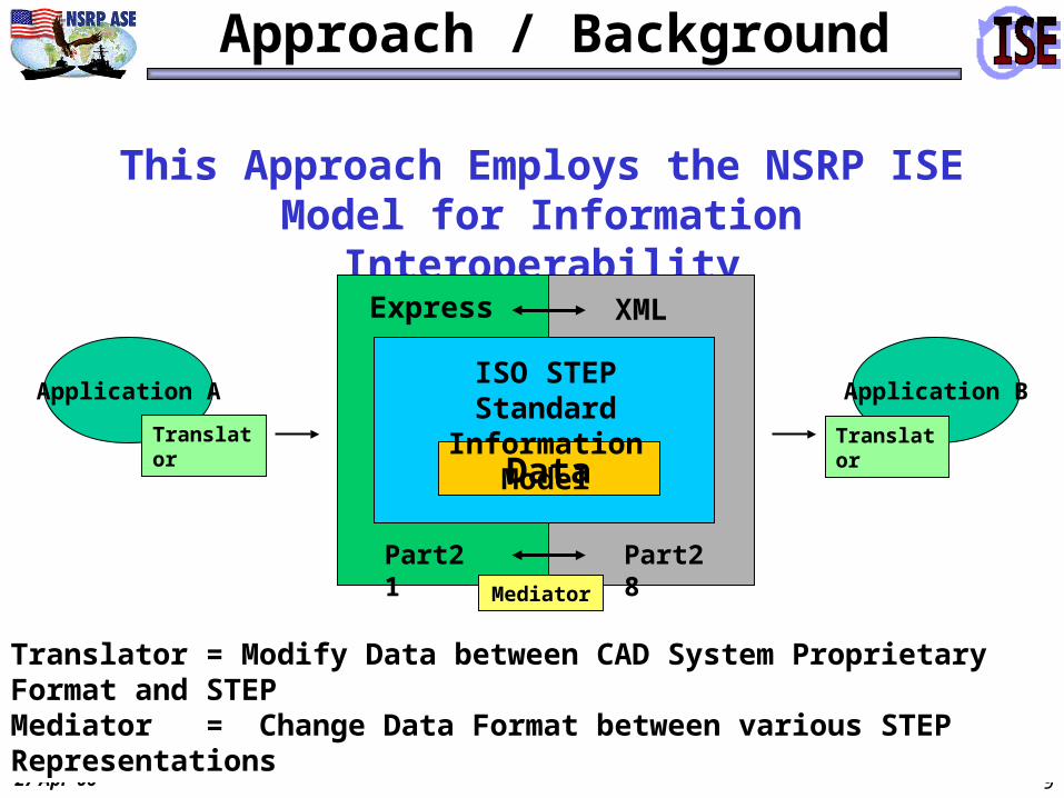
Approach / Background
This Approach Employs the NSRP ISE Model for Information Interoperability
Translator = Modify Data between CAD System Proprietary Format and STEPMediator = Change Data Format between various STEP Representations
Application A
Translator
Application B
Translator
Data
ISO STEP Standard Information Model
XMLExpress
Part21 Part28
Mediator

27 Apr ‘06 10
Systems Involved in the Interoperability Demo
Initial Design Detail Design Manufacturing Lifecycle Support
TRIBON ISDP
LEAPS
LEAPS
Engineering FEA Analysis
FORAN
Preliminary Arrangement
Feed Mfg from ISDP
ModifyArrangement
Partnership Yard
INTELLISHIP
Repair Shipyard
SuggestDesign
ChangesSubmit Design
ApprovalFinal Product Model Delivered to Navy
GDEB NGSS
Steel Processing
Navy AnalysisPrograms
Engineering Analysis
B
B
C
= Mediators Required
Concept & Preliminary Design
DetailDesign
Sener Intergraph
EBC
ADAPT
Key:
Atlantec
= Demonstrated = Not Demonstrated
ElectricalKSS/KM
NavyResponse
Center
AP215P21
AP215P28
AP215P28
AP218P28
AP218P28
AP209P21
AP215P21
AAP212P28
AP212P21
SubmitDesign
For Approval
Arrangements

27 Apr ‘06 11
Integrated Shipbuilding Environment
Washington DC • April 27, 2006
Arrangements Demonstration

27 Apr ‘06 12
Ship Arrangements Demo Details
Initial Design Detail Design Manufacturing Lifecycle Support
TRIBON ISDP
LEAPS
LEAPS
FORAN
Preliminary Arrangement
ModifyArrangement
Partnership Yard
INTELLISHIP
Repair Shipyard
SuggestDesign
ChangesSubmit Design
ApprovalFinal Product Model Delivered to Navy
B
B
= Mediators Required
Concept & Preliminary Design
DetailDesign
Sener
Intergraph
Key:
Atlantec
= Demonstrated = Not Demonstrated
NavyResponse
Center
AP215P21
AP215P28
AP215P28
AP215P21
SubmitDesign
For Approval
Arrangements
Navy AnalysisPrograms
Engineering Analysis

27 Apr ‘06 13
Overview – Tribon Translator
• Developed STEP AP215 Translator for Tribon Initial Design
• Translator Produces file in Part 28 ARM format defined by EB
• Worked with EB to test File Schema and Mediators
Atlantec Enterprise Solutions

27 Apr ‘06 14
Demo Scenario – Tribon Translator
Tribon Initial Design
AtlantecAP215
Translator
TribonOutput
Files
STEP / XMLAP 215 File
MediatorsSTEP
AP 215 File
FORAN
LEAPS
Translation Process – High Level

27 Apr ‘06 15
As-Is Process – Tribon Translator
Vendor Lock-in Ship designers and builders stay with one vendor to be able to transfer data between various design and manufacturing software packages
System-to-System Bridges Custom software can be created to link two software packages These solutions are fragile, as they must be updated with every version change in either software package Usefulness is limited to the two systems connected
Manual Reentry Ship designers and builders can manually reenter data in a second system This process is expensive, labor-intensive, and error prone
Initial Design Integration Options: Currently Available

27 Apr ‘06 16
ISE Process – Tribon Translator
No Vendor Lock-in Using STEP standards and translators ship designers and shipbuilders can move data between software packages provided by different vendors
No System-to-System Links Using STEP standards and translators there is no need to build system-to-system bridge software. A translator bridges each software package to the standard All software systems bridged to the standard are interoperable
No Manual Reentry With automated transfers via the standard, manual reentry can be avoided
Initial Design Integration Options: With STEP and ISE Translators

27 Apr ‘06 17
Overview – LEAPS AP215 Translators
Project accomplishments:
• Developed STEP AP215 Import and Export Translators for Navy LEAPS system.
• PDSC is ISO Editor of STEP AP215. Provided AP215 documents, ARM/AIM EXPRESS schemas, and training/consulting to ISE team.
• Developed and maintained ISE AP215 Implementation Agreements and Issues Logs for ISE Team.
• Submitted 20 SEDS (Standard Enhancement and Discrepancy System) to ISO for inclusion in next version of ISO AP215 standard.
Product Data Services Corporation (PDSC) for NSWC Carderock Division

27 Apr ‘06 18
Overview – LEAPS AP215 Translators
LEAPS – Leading Edge Application for Prototyping Systems
• Central Navy Repository for Ship design and analysis.
• Developed and supported by NSWC Carderock Division.
• Common database for 3D Product Model Data and Analysis results for new Ship Acquisition.
• Direct translators from ASSET for initial arrangements and to NAVSEA analysis software for performance and vulnerability assessments.

27 Apr ‘06 19
Overview – LEAPS AP215 Translators
LEAPS – Leading Edge Application for Prototyping Systems
Analysis Tools
Focus O bject M odel
M odelingTools
A SS E T
Part Library
R adar S ignature
IR S ign ature
Vulnerability
C ost
S im S m art
E lectrical Sys.
M anning
P ropulsors
R M &A
Structures
O ther CA D
O ther CA D
STEP
G atew ay
VisM ockUp
E ditor
Analysis Tools
Focus O bject M odel
M odelingTools
A SS E T
Part Library
R adar S ignature
IR S ign ature
Vulnerability
C ost
S im S m art
E lectrical Sys.
M anning
P ropulsors
R M &A
Structures
R adar S ignature
IR S ign ature
Vulnerability
C ost
S im S m art
E lectrical Sys.
M anning
P ropulsors
R M &A
Structures
O ther CA D
O ther CA D
STEP
O ther CA D
O ther CA D
STEP
G atew ay
VisM ockUp
E ditor G atew ay
VisM ockUp
E ditor

27 Apr ‘06 20
As-Is Process - LEAPS AP215 Translators
LEAPS – Leading Edge Application for Prototyping Systems
• Existing LEAPS geometry data exchange capability for IGES surfaces developed by NSWC Carderock Division.
• Previous STEP AP216 (surfaces) import and export translator project completed in 2003-04 by NSWCCD, PDSC, and Atlantec under Navy e-Business Office funding.
27 Apr ‘06 21
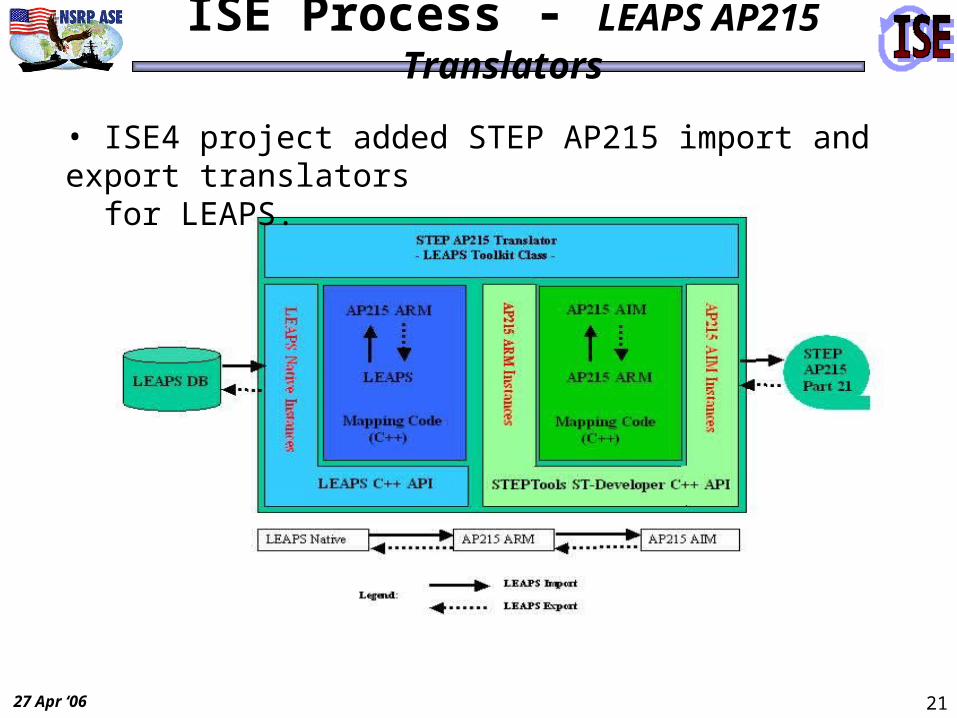
ISE Process - LEAPS AP215 Translators
• ISE4 project added STEP AP215 import and export translators for LEAPS.

27 Apr ‘06 22
Sample Processes-(LEAPS-CBD)
GRIDGEN
CFX
AUTOCADAutoCAD
LEAPS Product ModelLEAPS Product Model
• Generic Class Structure
• Product Model Schema– NAVSEA Ship Focus Object
Model
• Product Model Data
Design Product ModelIRENE
RTS
TSSM
SMP
ASAP/SVM
CONTAM
EXCEL-COST
T
T
T
T
T
T
T
TLEAPS/Editor
ASSET
SBAAT
T
T
Initialize Federates
T
Logged Fed’n Data
T
PRO/E
CATIA
T
ST
EP
/IGE
S
T
T
T
UGT
T
LEAPS/Editor
ST
EP
/IGE
S
CFX
GRIDGEN
CONTAM
Analysis
Developed and implementedby JS CBD FY02 & FY03
Virtual Mockup
Presentation Mgr
DOORS
Initialize Federates

27 Apr ‘06 23
LEAPS Activity
VisMockup
IRENE
EXCEL
TSSM
SMP
SVM/ASAP
EMENG
SDWE
GENERAL
LEAPSLEAPSProduct ModelProduct Model
• Generic Class Structure• Product Model Schema–NAVSEA Ship Focus Object Model
• Product Model Data
T
T
T
T
T
T
T
T
LEAPS Product ModelLEAPS Product Model
Presentation Mgr
RTS
ASSET Surface
ASSET Sub
HLA Federate(s)T
CAD
FORAN
TRIBONT
STEP(214)IGES
T
T
T
IntellShipT
CFX
RTC
BAM
GMULT/GCPL
T
MultihullArrange
LEAPSEditor
In Development ExistingBeta Code Other
STEP/IGES
T
T
SHIP AP’sSTEP(216)STEP(215)STEP(218)STEP(227)
T
Capture HLA Sim Data
SHIPIR
CONTAM
FKS
DOORS S3D
VERES
PlannedD
SWPE
27 Apr ‘06 24
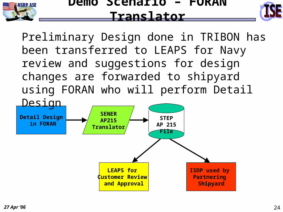
Demo Scenario – FORAN Translator
Detail Design in FORAN
ISDP used by Partnering Shipyard
LEAPS for Customer Review
and Approval
Preliminary Design done in TRIBON has been transferred to LEAPS for Navy review and suggestions for design changes are forwarded to shipyard using FORAN who will perform Detail Design
SENERAP215
Translator
STEPAP 215 File

27 Apr ‘06 25
SENER - FORAN
L I S T O F C O M P A R T M E N T S O F T H E T W R S H I P ’ S F O R A N 3 D M O D E L
C O M P A R T M E N T
N U M B E R
D E S C R I P T I O N L O N G .
P O S I T I O N S I
D E S H I P ’ S Z O N E
S e e F i g
1 L A Z A R E T T E F r . 2 5 – 2 8 P - S B E L O W M A I N D E C K 2
2 E N G I N E R O O M F r . 1 6 – 2 3 P - S B E L O W M A I N D E C K 1
3 P U M P R O O M F r . 1 2 – 1 6 P - S B E L O W M A I N D E C K 1
4 P R O V I S I O N S T O R E R O O M F r . 1 0 . 5 - 1 2 C B E L O W M A I N D E C K 2
5 O B S E R V E R S B E R T H I N G F r . 9 . 5 – 1 2 S B E L O W M A I N D E C K 2
6 C R E W B E R T H I N G F r . 6 – 9 . 5 P - S B E L O W M A I N D E C K 2
7 B O W T H U S T E R S P A C E F r . 4 . 5 – 6 P - S B E L O W M A I N D E C K 2
8 B O S U N S S T O R E S F r . 2 – 4 . 5 P - S B E L O W M A I N D E C K 2
9 V O I D S P A C E F r . 2 – 4 . 5 P - S D O U B L E B O T T O M 1
1 0 C H A I N S L O C K E R F r . 1 . 5 – 2 C B E L O W M A I N D E C K 2
1 1 C . O . S T A T E R O O M F r . 4 . 5 – 7 P D E C K H O U S E 3
1 2 C . P . O . S T A T E R O O M F r . 4 . 5 – 7 S D E C K H O U S E 3
1 3 W A S H R O O M , W C &
S H O W E R F r . 7 – 8 . 5 P D E C K H O U S E 3
1 4 E L E C T R I C A L
E Q U I P M E N T R O O M F r . 7 – 8 S D E C K H O U S E 3
1 5 A I R H A N D L I N G R O O M F r . 8 – 1 0 S D E C K H O U S E 3
1 6 G A L L E Y F r . 1 0 – 1 3 . 5 S D E C K H O U S E 3
1 7 B O S U N S ’ S L O C K E R –
D E C K G E A R F r . 1 3 . 5 –
1 4 . 5 S D E C K H O U S E 3
1 8 S H E L T E R D E C K A R E A F r . 1 3 . 5 – 1 5 P D E C K H O U S E
( O P E N A I R S P A C E ) 1
1 9 M E S S / L O U N G E F r . 8 . 5 –
1 3 . 5 P D E C K H O U S E 3
2 0 P I L O T H O U S E F r . 6 – 1 0 P - S P I L O T H O U S E 1
2 1 F O R E P E A K F r . ( - 2 ) – 2 P - S B E L O W M A I N D E C K 1
2 2 B A L L A S T T A N K N o . 1 F r . 6 – 9 S D O U B L E B O T T O M 3
2 3 B A L L A S T T A N K N o . 2 F r . 6 – 9 P D O U B L E B O T T O M 1
2 4 B A L L A S T T A N K N o . 3 F r . 2 3 – 2 5 S B E L O W M A I N D E C K 3
2 5 B A L L A S T T A N K N o . 4 F r . 2 3 – 2 5 P B E L O W M A I N D E C K 2
2 6 P O T A B L E W A T E R T A N K
N o . 1 F r . 1 2 . 5 –
1 5 . 5 S I N S I D E P U M P R O O M 2
2 7 P O T A B L E W A T E R T A N K
N o . 2 F r . 1 2 . 5 –
1 5 . 5 P I N S I D E P U M P R O O M 2
2 8 F U E L O I L T A N K N o . 1 F r . 9 – 1 2 S D O U B L E B O T T O M 3
2 9 F U E L O I L T A N K N o . 2 F r . 9 – 1 2 P D O U B L E B O T T O M 1
3 0 F U E L O I L T A N K N o . 3 F r . 1 6 – 2 2 C B E L O W E N G I N E R O O M 2
2 0
23
9
2 1
2 32 9
1 8
F i g . 1
1
3 0
2 7
2 6
6
4
5
78
1 0
2 5
F i g . 2
1 1
1 31 9
1 6
2 22 8
1 4
1 5
2 4
1 7
1 2
F i g . 3
L I S T O F C O M P A R T M E N T S O F T H E T W R
S H I P ’ S F O R A N 3 D M O D E L ( 1 o f 2 )
L I S T O F C O M P A R T M E N T S O F T H E T W R S H I P ’ S F O R A N 3 D M O D E L
C O M P A R T M E N T
N U M B E R
D E S C R I P T I O N L O N G .
P O S I T I O N S I
D E S H I P ’ S Z O N E
S e eF i g
3 1 F U E L O I L D A Y T A N K
N o . 4 F r . 2 3 - 2 4 S B E L O W M A I N D E C K 4
3 2 F U E L O I L D A Y T A N K
N o . 5 F r . 2 3 - 2 4 P B E L O W M A I N D E C K 4
3 3 L U B R I C A T I N G O I L
S T O R A G E T A N K F r . 2 3 - 2 3 . 5 P B E L O W M A I N D E C K 4
3 4 W A S T E O I L T A N K F r . 1 4 . 5 - 1 6 C I N S I D E P U M P R O O M 6
3 5 S E W A G E T A N K F r . 1 2 . 5 -
1 3 . 5 C I N S I D E P U M P R O O M 6
3 6 W A S H R O O M , W C &
S H O W E R F r . 9 . 5 - 1 2 P B E L O W M A I N D E C K 5
3 7 P A S S A G E W A Y F r . 8 . 5 -
1 0 . 5 C B E L O W M A I N D E C K 5
3 8 P A S S A G E W A Y F r . 7 - 8 . 5 P - S D E C K H O U S E 4
3 9 S T A I R S F r . 8 - 1 0 . 5 S D E C K H O U S E 4
4 0 E X H A U S T T R U N K - I N -
D E C K H O U S E F r . 1 4 . 5 - 1 5 S D E C K H O U S E 4
4 1 V E N T T R U N K - I N -
S H E L T E R D E C K A R E A ( V E N T I L A T O R ’ S B A S E )
F r . 1 4 . 5 - 1 5 P D E C K H O U S E 5
4 2 S T A I R S F r . 1 3 . 5 - 1 5 S D E C K H O U S E 4
4 3 P A S S A G E W A Y F r . 2 3 - 2 5 C B E L O W M A I N D E C K 4
4 4 C Y L I N D E R L O D G I N G T H E B O W T H R U S T E R
F r . 5 1 / 3 P - S
C I L I N D R I C A L H O L L O W I N S I D E B O W T H R U S T E R
S P A C E
6
4 5
H O L L O W I N S H I P ’ S H U L L - M A I N D E C K
D U E T O T O R P E D O ’ S R A M P
F r . 2 0 . 5 - 2 8 S
O N T O P O F L A Z A R E T T E ,
B A L L A S T T K . N o . 3 , F U E L O I L T A N K
N o . 4 A N D E N G I N E R O O M
5
4 6 E X H A U S T T R U N K -
I N S I D E P U M P R O O M F r . 1 4 . 5 - 1 6 S I N S I D E P U M P R O O M 5
4 7 V E N T T R U N K -
I N S I D E P U M P R O O M F r . 1 4 . 5 - 1 6 P I N S I D E P U M P R O O M 5
3 1
3 2
3 3
3 83 94 2
4 34 0
F i g . 4
F i g . 5
4 5
4 6
4 74 1
3 6
3 7
4 5
F i g . 6
4 4
3 43 5
L I S T O F C O M P A R T M E N T S O F T H E T W R
S H I P ’ S F O R A N 3 D M O D E L ( 2 o f 2 )
FORAN Ship ArrangementsDetailed Design
Selective STEP Export to LEAPS
SpacesDeck zones
Zones
( P21 AP215-AIM STEP FILE)
Decks and Bulkheads
Details
List of Ship Spaces
Hull Forms
FORAN – ISE4 AP215 STEP Translator
FORAN – ISE4 Import STEP Translator
TRIBON - LEAPS
AP215 – SHIP ARRANGEMENTS

27 Apr ‘06 26
Demo Scenario - LEAPS AP215 Import
Part21 file from FORAN

27 Apr ‘06 27
Demo Scenario - LEAPS AP215 Import
Imported Product Model Data in LEAPS

27 Apr ‘06 28
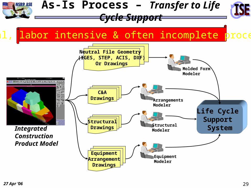
Overview – Transfer to Life Cycle Support
• Transfer construction product model to Life Cycle Support for– Engineering support
• Onboard applications• Distance support• Maintenance aids• Analysis tools
– Decision support / simulation– Logistics support
• Typical deliverables are drawings / documents– Must be re-converted to electronic data– Manual, labor intensive, incomplete process– Integrated Product Model often lost
• ISE information models designed to interoperate and preserve integrated product model – Supports automated, complete process
27 Apr ‘06 29
As-Is Process – Transfer to Life Cycle Support
Life Cycle Support SystemIntegrated
ConstructionProduct Model
Neutral File Geometry (IGES, STEP, ACIS, DXF)
Or Drawings
C&ADrawings
EquipmentArrangement
Drawings
StructuralDrawings
Molded FormModeler
ArrangementsModeler
StructuralModeler
EquipmentModeler
Manual, labor intensive & often incomplete process

27 Apr ‘06 30
ISE Process – Transfer to Life Cycle Support
Life Cycle Support System
Integrated ConstructionProduct Model
AP 216Molded Form
Data
AP 215 Arrangements
Data
AP 218Structural
Data
AP 227 Equipment
Data
Highly automated, integrated, complete process
ISETranslators
ISETranslators
ISETranslators
ISETranslators
Integrated Life CycleProduct Model

27 Apr ‘06 31
Demo Scenario–Transfer to Life Cycle Support
Integrated ConstructionProduct Model
AP 216Molded Form
Data
AP 218Structural
Data
AP 227 Equipment
Data
ISETranslators
ISETranslators
ISETranslators
ISETranslators
Integrated Life CycleProduct Model
ISDP: Integrated Ship Design & Production
IntelliShip
Previous exchange
Compartments created using existing molded forms
ISE exchanges interoperate & preserve product model
AP 215 Arrangements
Data

27 Apr ‘06 32
Electrical Demo Details
Initial Design Detail Design Manufacturing Lifecycle Support
ISDP
Engineering FEA Analysis
Preliminary Arrangement
ModifyArrangement
Repair Shipyard
Steel Processing
= Mediators Required
Concept & Preliminary Design
Intergraph
Key: = Demonstrated = Not Demonstrated
ElectricalKSS/KM
AAP212P28
AP212P21
DetailDesign
Arrangements

27 Apr ‘06 33
Project Objectives
Exchange and ARCHIVE electrical shipbuilding data using STEP AP212 (developed by the auto industry).
Adopt XML to exchange STEP data.
Lay the groundwork to exchange data between CAD and knowledge-based software systems using STEP.
Leverage existing initiatives in the industry (STEP Part 21, STEP Part 28, STEP AP212, and the Navy XML repository).
Publish project results.

27 Apr ‘06 34
Knowledge Systems Solutions
Knowledge management products and expert system software
Navy (SPAWAR) C4ISR
Ship Shore Installation Design Tool
(SSIDT)
KSS KnowledgeManager
Product to createuser-defined
knowledge bases
Air Force (OC-ALC) SBIR
Knowledge-based reverseengineering & automatic
creation of 3D CAD models
Navy (NAVSEA) SBIR
Knowledge-based retentionof shipbuilding expertise
*
* *
Transition of NSRP STEP translator technology*

27 Apr ‘06 35
Spiral Development
Knowledge-based system STEP XML AP212
TWRLightingTWR
Power Distribution
SystemSpec
FrameworkDesign
Single C4ISREquipment
Single C4ISRCircuit
Full C4ISRSystem
Generic Objects
DesignConfigurator
Integrated Prototype
Component Design File Data
Import
NavyAir Force
Commercial
STEP – Data – Translator
Full Engineering& Design Data Sets

27 Apr ‘06 36
Knowledge Management Demonstration
TWR Power Distribution System
Collect data and information into a knowledge base
Perform calculations and design functions

27 Apr ‘06 37
Component Design Framework
KnowledgeBasedSystem
ComponentPart
Catalog
ObjectClasses
STEP.stpFiles
AP SchemasAP
SchemasCAD Systems
Med
iato
rsM
edia
tors
DesignConfigurator
AP Schemas
AP Schemas
AP Schemas
Design File
Component Structure
CDF • Component Structure
• Multiple AP’s & Schemas
• Auto-configured Objects
• Structured Design File
• KB CAD (future)
• CAD KB (future)

27 Apr ‘06 38
Electrotechnical Results
Developed Component Design Framework for data translation and archival using STEP AP212.
Knowledge Management (knowledge & rules)
Engineering Data (results)
Created reusable STEP toolsets (mediator stylesheets) for DoN repository.
Tested AP212 with diverse electrotechnical test cases.
Demonstrated the joint use of STEP and XML with new programming resources.

27 Apr ‘06 39
Electrotechnical Future
– Continued joint service implementation and benefit.
– ISE4 follow-on project• Facilitates detailed engineering along with early
conceptual electrical engineering.
• Integrates knowledge management with 2D and 3D CAD via STEP formatted files.
– Automatically generate knowledge bases from existing CAD data elements.

27 Apr ‘06 40
Engineering Analysis Demo Details
DetailedDesign Stage
NGSS, Intergraph
EBCElectrical
Concept & Preliminary Design Engineering
FEA Analysis
XSLTs
NGSS, Intergraph
EBC
ADAPT
AP218P28
AP209P21
ISDP
Steel Processing
Initial Design Detail Design Manufacturing Lifecycle Support
DetailDesign
Arrangements

27 Apr ‘06 41
Engineering Analysis Project
Final DemonstrationApril 27, 2006
Washington, DC
ISE-4
L = Left Screen

27 Apr ‘06 42
Engineering Analysis Project
Final DemonstrationApril 27, 2006
Washington, DC
ISE-4
R= Right Screen
Note: This was a simultaneous 2-screen demo; L = Left screen, R = Right screen.
27 Apr ‘06 43
Participating Organizations:
• General Dynamics / Electric Boat – Task Lead
• Northrop Grumman Ship Systems
• Intergraph Corporation
Engineering Analysis Task
L

27 Apr ‘06 44
Individual Participants:• Burt Gischner
• Ron Wood
• Steve Gordon
• Denny Moore
• Ted Briggs
• Art Hundiak
• Tom Rando
• Heidi Preston
• Steve Skrabacz
Engineering Analysis Task
R

27 Apr ‘06 45
Engineering Analysis Task
Focus and Outline:
• Multiple ISO STEP Application Protocols (APs)– Primarily AP218 and AP209
• Different file exchange formats– Traditional STEP Express and XML forms
• Leverage existing CAE software
Demonstrations:
• Demo 1 - Accommodating different formats– Both Part21 (Express) and Part28 Ed. 2 (XML)– Using mediation (XSLT transformation)
• Demo 2 - Using parametric geometry – AP218 ‘Implicit’ and ‘Explicit’ Geometry– Creating explicit from implicitL

27 Apr ‘06 46
Engineering Analysis Task Goals
Task Goals and Objectives:
• Extend interoperability capabilities by employing both the newer shipbuilding APs and the other existing ISO STEP 10303 standards.
• Build on work accomplished under previous ISE projects and related efforts.
• Illustrate flexible use of both STEP Express and XML formats for exchange and mediation.
• Demonstrate TWR structural model exchange from AP218 to AP209 for use with various engineering finite element analysis software packages
• Leverage these methodologies for both future Product Lifecycle Management (PLM) and Long Term Data Retention (LTDR) efforts.L

27 Apr ‘06 47Ready for Implementation
Interoperability
Extend ISO 10303 Interoperability
R

27 Apr ‘06 48
• The utility of the ISO STEP 10303-209 (AP209) for supporting interoperability and collaborative design (combining design geometry with detailed finite element analysis) has already been demonstrated in other venues (e.g. PDES).
• All of that collaboration has been based upon exchange of traditional STEP files encoded in Express (Part21).
• In this ISE-4 task we demonstrate extensions to that approach by integrating with STEP application protocols for ship structure (primarily AP218), and by employing more flexible collaboration and exchange scenarios using XML (Part28) encoded files.
Engineering Analysis Approach
PDES, Inc. R
R

27 Apr ‘06 49
Data
ISO STEP Standard Information Model
<XML>Express
Part21 Part28
The STEP Standards can be delivered (“wrapped”) in multiple forms, yet contain
exactly the same data!
ISO STEP 10303 Information Model = Core Content
ISE Paradigm
R

27 Apr ‘06 50
XML Mediation Addresses CAx Interoperability among the Ship APs and with other Existing ISO STEP APs
Ship CAD Tools
STP (Express) Files
XML Files
XSLTInteroperabilityCAE
Analysis Tools
Engineering Analysis Approach / Progress
CAx = CAD / CAE / CAM
CAD CAE
CAD CAM
L

27 Apr ‘06 51
Interoperability Backdrop
Ship CAD Tools
CAE Tools
STP
AP218 AP209
XML
R

27 Apr ‘06 52
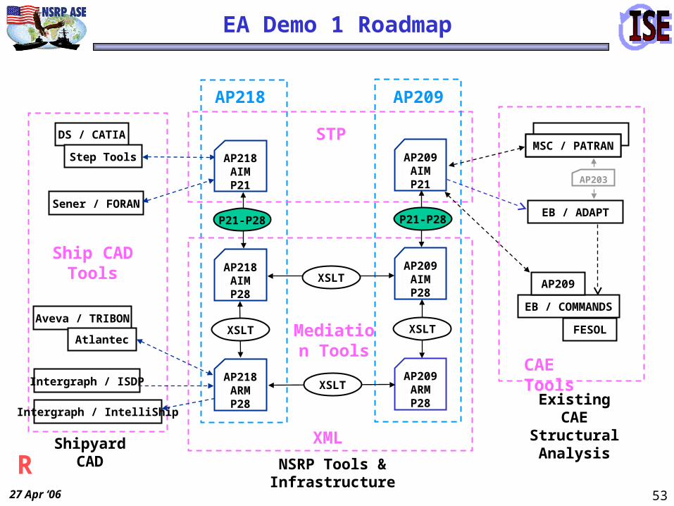
EA Demo 1 Roadmap
Ship CAD Tools
CAE Tools
AP218
STP
AP209
XMLShipyard CAD
DS / CATIA
Sener / FORAN
Intergraph / ISDP
Aveva / TRIBON
Intergraph / IntelliShip
Atlantec
Step Tools
AP218ARMP28
AP218AIMP21
AP209AIMP21
EB / COMMANDS
FESOL
AP209
Existing CAE Structural Analysis
MSC / PATRAN
EB / ADAPT
AP203
?
R
27 Apr ‘06 53
Ship CAD Tools
CAE Tools
AP218
STP
AP209
AP209AIMP21
XML
Mediation Tools
AP218AIMP28
AP209AIMP28
AP209ARMP28
XSLT XSLT
P21-P28 P21-P28
XSLT
XSLT
NSRP Tools & Infrastructure
Shipyard CAD
DS / CATIA
Sener / FORAN
Intergraph / ISDP
Aveva / TRIBON
Intergraph / IntelliShip
EB / COMMANDS
FESOL
AP209
Existing CAE Structural Analysis
Atlantec
Step Tools
AP218ARMP28
AP218AIMP21
MSC / PATRAN
EB / ADAPT
AP203
EA Demo 1 Roadmap
R

27 Apr ‘06 54
Actual EA Demo 1 Flow
DS / CATIA
Ship CAD Tools
Sener / FORAN
Aveva / TRIBON
MSC / PATRAN
CAE Tools
EB / COMMANDS
FESOL
AP209
STI
AP218ARMP28
AP218AIMP21
Atlantec
AP218
AP209AIMP21
STP
AP209
AP218AIMP28
AP209AIMP28
AP209ARMP28
XSLT XSLT
P21-P28 P21-P28
XSLT
XSLT
XML
Mediation
Intergraph / IntelliShip
EB / ADAPT
AP203
Intergraph / ISDP
L

27 Apr ‘06 55
XML
STPSTP
NSRP ISE Demo GUI
Mediator GUI
R

27 Apr ‘06 56
Multiple APs
• Different ISO STEP Application Protocols have differing file content.– AP218 (Ship Structures) vs. AP209 (Composite and Metallic Structural
Design & Analysis).
• Several ship CAD vendors have selected XML (Part28) format for data exchange.
• Other CAx (CAD and CAE) vendors employ existing (older) ISO STEP exchange files in Express (Part21) format.
• AP203 (IS, 1994) has had more than a decade of usage. Along with AP214, they are the most commonly used APs. They are pervasively used for CAD geometry exchange in various industries today.
How can that work?
L

27 Apr ‘06 57
AP218: Ship Structures
L

27 Apr ‘06 58
Configuration Control, Approvals
• Part, product definitions
• Finite element analysis model, controls, and results
Configuration Control, Approvals
• Part, product definitions
• Finite element analysis model, controls, and results
Analysis Discipline Product Definitions
• Finite Element Analysis–Model (Nodes, Elements, Properties,...)–Controls (Loads, Boundary Constraints,...)
–Results (Displacements, Stresses,...)
• Analysis Report
Analysis Discipline Product Definitions
• Finite Element Analysis–Model (Nodes, Elements, Properties,...)–Controls (Loads, Boundary Constraints,...)
–Results (Displacements, Stresses,...)
• Analysis Report
Design Discipline Product Definition
• Shape Representations
• Assemblies
Design Discipline Product Definition
• Shape Representations
• Assemblies
Information Shared Between Analysis & Design
• 3D Shape Representations
• Composite Constituents
• Material Specifications & Properties
• Part Definitions
Information Shared Between Analysis & Design
• 3D Shape Representations
• Composite Constituents
• Material Specifications & Properties
• Part Definitions
Composite Constituents
• Ply Boundaries, Surfaces
• Laminate Stacking Tables
• Reinforcement Orientation
Composite Constituents
• Ply Boundaries, Surfaces
• Laminate Stacking Tables
• Reinforcement Orientation
Material Specifications & Properties
• Composites
• Homogeneous (metallics)
Material Specifications & Properties
• Composites
• Homogeneous (metallics)
3D Shape Representation
• AP202/203 Commonality Plus Composite Specific 3D Shapes
– Advanced B-Representation– Faceted B-Representation– Manifold Surfaces With Topology– Wireframe & Surface without Topology– Wireframe Geometry with Topology– Composite Constituent Shape Representation
3D Shape Representation
• AP202/203 Commonality Plus Composite Specific 3D Shapes
– Advanced B-Representation– Faceted B-Representation– Manifold Surfaces With Topology– Wireframe & Surface without Topology– Wireframe Geometry with Topology– Composite Constituent Shape Representation
AP209: Composite & Metallic Structural Analysis & Related Design
R

27 Apr ‘06 59
ISO STEP 10303-218 (AP218) Ship Structures
PDM
Geometric Shape Representations
Structural Parts and Features
CAD
Configuration Management, Class Approval
General Characteristics, Hull Cross Section, Weight Description Production Design &
Engineering Data
Wireframe, Non_Manifold Surfaces, Brep Solids
ISO STEP 10303-218 (AP218)
“Explicit” Geometry “Implicit” Geometry
(Parametric Geometry)
L

27 Apr ‘06 60
PDM
Product Data Management
PDM Info
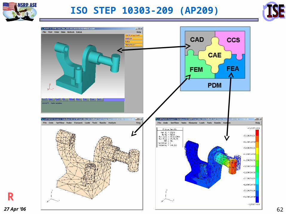
AP209 = CAD + CCS + CAE + FEM + FEA + PDM
ISO STEP 10303-209 (AP209)
One can use STEP APs with any one or more of these pieces.
AP209
CADNominal CAD Geometry
CAEIdealized CAE “Simulation-Specific”
Geometry
FEAFinite Element Analysis FEA
Controls & Results
FEMFinite
Element Model(s) FEM
CCS
Composite Constituent
Shape(s) CCS
R

27 Apr ‘06 61
AP218: Ship Structures
Structural System Tank StructureL
27 Apr ‘06 62
ISO STEP 10303-209 (AP209)
R

27 Apr ‘06 63
This NSRP ISE-4 Task Demo
PDM
First Step is to Create a Starting AP209 File with
Explicit Geometric Shape Representations
CAD
Configuration Management, Class Approval
Multiple STEP Application Protocols, Different Formats: XML (P28), Express (P21)
AP218 P28 ARM
PDM
CAD
AP209 P21 AIM
XSLTs
L

27 Apr ‘06 64
PDM
CAD
PDM
CAE
FEM FEA
AP209
The Next Demo Step is to Illustrate Analysis of the
Exchanged Ship Structure
• Automated Creation of Idealized (Analysis) Geometry• Construct the Finite Element Model(s)• Solve, Display, and Interpret Analysis Results
All These can be Merged into a Single “Growing” AP209 File or Repository for LTDR and PLM
This NSRP ISE-4 Task Demo
R
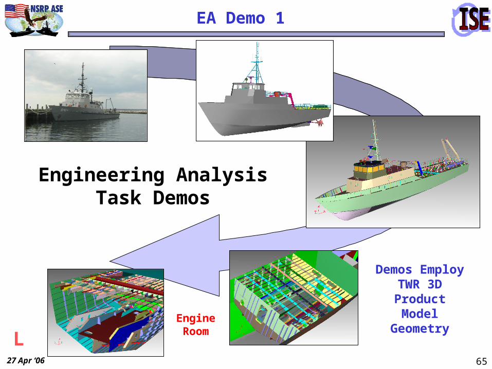
27 Apr ‘06 65
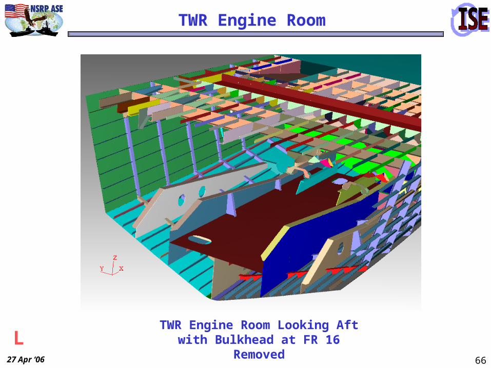
Demos Employ TWR 3D
Product Model GeometryEngine
Room
Engineering Analysis Task Demos
EA Demo 1
L
27 Apr ‘06 66
TWR Engine Room Looking Aft with Bulkhead at FR 16 Removed
TWR Engine Room
L

27 Apr ‘06 67
Engines are Supported on Outboard and
Inboard Girders
TWR Engine Room
Twin Caterpillar Diesel Propulsion
EnginesFuel Oil Tank Top
R

27 Apr ‘06 68
Selected TWR Engine Room Solid Model Geometry with Port
Caterpillar Engine
Partial Design Change - Additional Brackets Inserted at FR 17 & FR 19
TWR Engine Room
L

27 Apr ‘06 69
Selected TWR Engine Room Solid Model Geometry with Port
Caterpillar Engine
TWR Engine Room
R

27 Apr ‘06 70
Port-Side Outboard Girder - Solid Model
Geometry for Analysis
TWR Engine Room Fuel Oil Tank & Engine Support Structure
Shown in Intergraph’s ISDP Software
Demo Geometry in ISDP
L

27 Apr ‘06 71
Demo 1
Engineering Analysis Task
Demonstrations:
• Demo 1 - Accommodating different formats– Both Part21 (Express) and Part28 Ed. 2 (XML)– Using mediation (XSLT transformation)
• Demo 2 - Using parametric geometry – AP218 ‘Implicit’ and ‘Explicit’ Geometry– Creating explicit from implicit
L

27 Apr ‘06 72
Demo 1
Engineering Analysis Task
Demonstrations:
• Demo 1 - Accommodating different formats– Both Part21 (Express) and Part28 Ed. 2 (XML)– Using mediation (XSLT transformation)
• Demo 2 - Using parametric geometry – AP218 ‘Implicit’ and ‘Explicit’ Geometry– Creating explicit from implicit
R

27 Apr ‘06 73
Port-Side Outboard Girder - Solid Model Geometry
Outboard Girder – Mid-Surface Shell Geometry for Analysis
Demo Geometry
Nominal (CAD) and Idealized (Analysis) Geometry in EB’s ADAPT code
L

27 Apr ‘06 74
Outboard Girder – Shell Finite Element Analysis Model
6 “G” Simulated Shock Loads Applied in Vertical and Athwartship Directions
Shock Stress FE Analysis Model
L
27 Apr ‘06 75
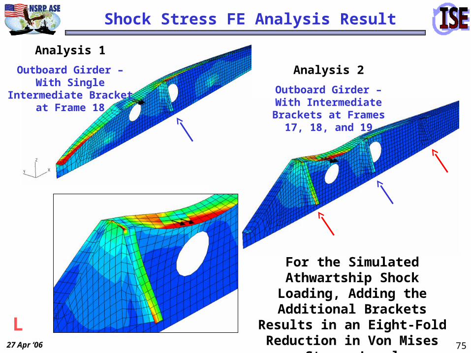
Analysis 2
Outboard Girder – With Intermediate Brackets at
Frames 17, 18, and 19
Analysis 1
Outboard Girder – With Single Intermediate Bracket at Frame 18
For the Simulated Athwartship Shock Loading, Adding the
Additional Brackets Results in an Eight-Fold Reduction in
Von Mises Stress Level
Shock Stress FE Analysis Result
L

27 Apr ‘06 76
Demo 2
Engineering Analysis Task
Demonstrations:
• Demo 1 - Accommodating different formats– Both Part21 (Express) and Part28 Ed. 2 (XML)– Using mediation (XSLT transformation)
• Demo 2 - Using parametric geometry – AP218 ‘Implicit’ and ‘Explicit’ Geometry– Creating explicit from implicit
R

27 Apr ‘06 77
AP218 Implicit Geometry
Various parts and features have parametric definitions in AP218 implicit geometry.
T Bar Cross Section Drain Hole Cutout
Bulbflat Cross Section
Outward Round Corner Cutout
L

27 Apr ‘06 78
EA Demo 2 uses ESTEP AP218 Test Case 2 (based on TWR Frame 12) from the ISE-2 project as input.
A prototype demonstrator code creates the explicit geometry, visualizes both, allows parametric change, an exports a STEP file.
EA Demo 2
L

27 Apr ‘06 79
Ship CAD Tools
CAE Tools
AP218
STP
AP2XX
AP203AIMP21
DS / CATIA
Sener / FORAN
EB / COMMANDS
FESOL
AP209
Existing CAE Structural Analysis
Step Tools AP218AIMP21
MSC / PATRAN
EB / ADAPT
AP203
EA Demo 2 Roadmap
STEPP21
Reader
3DViewer
MathLib
‘OneStop’
AIM218
Valid.
ManifoldSolid
Generator
ARMLister
PrototypeDemonstrator
AP218 Implicit to Explicit Geometry
& Visualizer
Implicit & ExplicitGeometry
Explicit Geometry
• Modular Java software
• Multiple project funding & support (EB, CNST, ISE)
ImplicitGeometry
Explicit Geometry
L

27 Apr ‘06 80
EA Demo 2
Part Selector and Parameter Change
Implicit (Parametric)
Geometry
CreatedExplicit
GeometryL
27 Apr ‘06 81
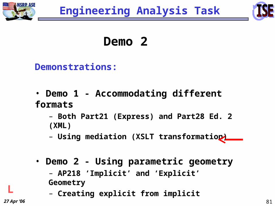
Demo 2
Engineering Analysis Task
Demonstrations:
• Demo 1 - Accommodating different formats– Both Part21 (Express) and Part28 Ed. 2 (XML)– Using mediation (XSLT transformation)
• Demo 2 - Using parametric geometry – AP218 ‘Implicit’ and ‘Explicit’ Geometry– Creating explicit from implicit
L

27 Apr ‘06 82
60 Degree Bevel
Outward Round Corner
Circular Cutout
Round Corner Rectangular Cutout
Inward Round CornerExamples of AP218
Parametric Features
EA Demo 2 – Implemented Features
L

27 Apr ‘06 83
AP218
ImplicitGeometry
Explicit Geometry
AP203
1. Implicit Explicit
2. Solid Import
3. Solid (TET) Meshing
EA Demo 2A
FEMAP Example
L

27 Apr ‘06 84
• It is an innovative integration of STEP and XML technologies– Supports sharing of geometry & geometric product models
• It employs a permissive (mediation) architecture– Lets each enterprise choose its own tool set
• It is accessible to both large and small shipyards– The only system dependency is Web infrastructure– Utilizes open standards
• It can be incorporated into CAD platforms used by U.S. shipbuilders and into software from other collaborating vendors
These demos show that the ISE approach and architecture do represent an innovative, practical solution to the information interoperability challenge.
ISE Approach
L

27 Apr ‘06 85
Steel Processing Demo Details
Initial Design Detail Design Manufacturing Lifecycle Support
ISDP
Engineering FEA Analysis
Preliminary Arrangement
Feed Mfg from ISDP
ModifyArrangement
Partnership Yard
Repair ShipyardGDEB NGSS
Steel Processing
= Mediators Required
Concept & Preliminary Design
DetailDesign
Intergraph
Key: = Demonstrated = Not Demonstrated
Electrical
AP218P28
Arrangements

27 Apr ‘06 86
Agenda - Steel Processing
• Objectives/Proposed scope
• Manufacturing Rules Description/ Applicability
• Demonstration Scenario
• Benefits

27 Apr ‘06 87
Objectives/Scope
• General Objectives (from NSRP SIP)– Decouple CAM from CAD – Enable efficient partnering among yards
• Project Scope– Create a framework for defining manufacturing
rules/processes– Develop a Yard-Neutral Mfg Model (STEP AP218)
• Suitable for work package definition
• Make recommended enhancements to specification as required
– Apply manufacturing rules to generate a manufacturing product model that respects the requirements of a given yard

27 Apr ‘06 88
Usage Scenario S
hip
yard
A
Shop B
STEP 218STEP 218
Sh
ipya
rd B
Shop A
STEP 218 STEP 218
CAD(Detailed Design)
Steel Processor(Lofting/
Mfg Engineering)
Steel Processor(Lofting/
Mfg Engineering)
Mfg Rules
Mfg Rules

27 Apr ‘06 89
Mfg Product Model
Shell Plate Design
CAD
Develop Flat Plate
Specialized Macro
Add Excess Stock for Rolling
Manufacturing Rule
Adjust Size for Weld Shrinkage
Manufacturing Rule
Yard Processes and Assembly Plan
Add Edge Prep & Punch-marking
Sourc
ePro
cess
ManufacturingDesign

27 Apr ‘06 90
Rules Application
• Data Creation– Creation of manufacturing data based on the input data and rules
– Examples• Feature definition (edge preps, added/removed mat’l)
• Annotation creation and positioning
• Process definition
• Data extractions for post-processing applications (reports, mfg aids, nesting)
• Data Verification– Check the data for conformance to a set of yard-specific processes, geometry
correctness (e.g., closed parts), consistency, and produce-ability
– Examples• Data integrity (content, structure, associations)
• Geometry correctness
• Structural part relationships
• Correlation of processes applied to structural data

27 Apr ‘06 91
Demonstration Example
Deck Plates
Bulkhead

27 Apr ‘06 92
Yard-Specific Annotation Ex.
Thickness Throw Indicator(Northrop Grumman Ship Systems)
Thickness Throw Indicator(General Dynamics Electric Boat)
Stiffener
Marking Line

27 Apr ‘06 93
Demonstration ScenarioN
ort
hro
p G
rum
man
Avo
nd
ale
Shop B
STEP 218
Gen
eral
Dyn
amic
sE
lect
ric
Bo
at
Shop A
Launch Demo
STEP 218
1
2
ISDPISDP Steel ProcessorSteel Processor
Steel ProcessorSteel Processor
1Apply manufacturing rules for NG Avondale
2Apply manufacturing rules for GD Electric Boat
STEP 218
Mfg Rules
STEP 218
Mfg Rules

27 Apr ‘06 94
Benefits of Approach - Steel Processing
• Explicit definition and application of rules to structural data– Maintained separate from design/lofting systems– Streamline manufacturing product model creation
and verification
• Evolution of ship structural standards– Use STEP specifications as the native
import/export format and as a framework for the internal structure
27 Apr ‘06 95
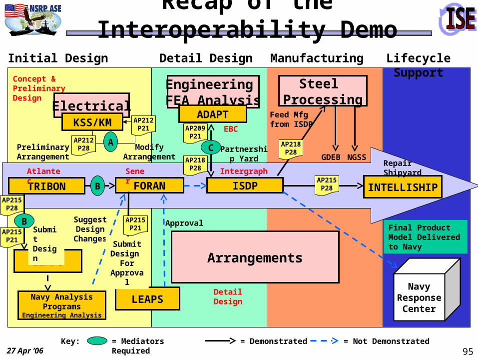
Recap of the Interoperability Demo
Initial Design Detail Design Manufacturing Lifecycle Support
TRIBON ISDP
LEAPS
LEAPS
Engineering FEA Analysis
FORAN
Preliminary Arrangement
Feed Mfg from ISDP
ModifyArrangement
Partnership Yard
INTELLISHIP
Repair Shipyard
SuggestDesign
ChangesSubmit Design
ApprovalFinal Product Model Delivered to Navy
GDEB NGSS
Steel Processing
B
B
C
= Mediators Required
Concept & Preliminary Design
DetailDesign
Sener Intergraph
EBC
ADAPT
Key:
Atlantec
= Demonstrated = Not Demonstrated
ElectricalKSS/KM
NavyResponse
Center
AP215P21
AP215P28
AP215P28
AP218P28
AP218P28
AP209P21
AP215P21
AAP212P28
AP212P21
SubmitDesign
For Approval
Arrangements
Navy AnalysisPrograms
Engineering Analysis

27 Apr ‘06 96
Availability of ISE Project Results
• ISE Project has:– Developed Information Models based on STEP – Created Mediator Tools– Verified that the above meet requirements of U.S. shipyards and
work with currently available CAD tools– Published Implementors Agreements to enable others to use these
tools effectively– Registered ISE Schemas with the DONXML Repository– Identified proposed changes/corrections to ISO STEP Standards– Created a Website to contain the relevant software tools, schemas,
etc. as provided by the ISE Project
• www.isetools.org– JEN-X Mediator from EXPRESS to XML will be publicly
available on Sourceforge and PDES, Inc. Websites

27 Apr ‘06 97
Goal: Implement in Production
• The ISE Project has developed tools and demonstrated interoperability between shipyards in the areas of:– Structure– Piping– HVAC– Common Parts Catalog Interfaces– Ship Arrangements– Electrical– Engineering Analysis– Steel Processing
• The goal of current and future efforts is to make these techniques and tools available in production and to all U.S. shipyards– STEP Shipbuilding Translators– XML Tools– Common Parts Catalog Interfaces
• A Website has been established to contain the relevant software tools, schemas, etc. as provided by the ISE Project– www.isetools.org
ISE2
ISE3
ISE4

27 Apr ‘06 98
Continuing Efforts
• An ISE4 Follow-On Project was awarded for 2006: – Electrical: Finish task including addition of 3D information– Program Management: Continue support and involvement of
ISO and DONXML activities
• An ISE Systems Technology Panel Project was awarded for 2006:– Steel Processing: Continue efforts with emphasis on STEP-NC
• Future Projects: Complete the Information Interoperability Roadmap– Goal is to turn all boxes “Blue”– ISE Project is providing tools to turn boxes from “Red” to
“Yellow” and then to “Green”– Customer must invoke Requirements on Contracts in order to
get these tools Implemented in Production

27 Apr ‘06 99
Information Interoperability Roadmap
Ship Product Model Data
Ship Structural Envelope
Distribution Systems
Equipment / Subsystems
Life Cycle Maintenance
Miscellaneous
HVACISO AP 227:2005
PipingISO AP 227:2005
Ship ArrangementISO AP 215:2004
Ship Moulded FormsISO AP 216:2003
Ship StructuresISO AP 218:2004
Reference Data Libraries
ISO 15926
Common Parts Catalog (CPC)
Mechanical SystemsISO AP 227:2005
Cable TraysISO AP 227:2005
Finite Element Analysis
ISO AP 209:2001
Product Config/ Geometry
ISO AP 203:1994
Systems EngineeringISO AP 233
Computational Fluid DynamicsISO AP 237
Logistics / SparesISO AP 232:2002
Outfit & FurnishingsNSRP 0428:1992
Manufacturing Support
ISO APs 224, 238, 240
Standard Approved
Information Model
Prototype Translators
Testing Framework
Deployment, integration,testing
Standard In Work
Product Life Cycle SupportISO AP 239
ElectricalISO AP 212:2001
Note: Circled boxes have been addressed under the ISE Project

27 Apr ‘06 100
Conclusions• These testing, modeling, and simulation efforts are part of
an attempt to develop a suite of product model data exchange tools that will enable U.S. shipyards to become more productive
• These efforts revolve around implementation of the ISO 10303 STEP Shipbuilding standards and XML technology
• The APs that enable these exchanges have completed their development and approval as International Standards
• The primary focus has shifted to testing and validating their implementations
ISE Tools Enable Interoperability between Shipyards and Reduce the Life Cycle Cost of Ships

27 Apr ‘06 101
• Two major challenges lie ahead of us:– Commercialization of this technology
– Continuing to prototype standards based data exchange in other application areas
• In order to increase the availability and lower the price of production ready tools:– The ship owner / operator needs to insist that data be delivered in a system
neutral format
– The shipbuilder needs to insist that STEP functionality be an integral part of computer software products
• The next challenge is to move this technology into the mainstream and insure that the technology is mature enough to transition into commercial CAD, CAE, CAM, and PDM products
Challenges

27 Apr ‘06 102
Summary
• Enabling interoperability is a major challenge in achieving the goals of NSRP
• Achieving these goals will have a major impact on reducing the cost of ships
• The ISE Project is attacking these problems in many different disciplines and environments
• Although ISE has been very successful, much work remains to achieve our goals


