www.iaset.us edi [email protected]
MIXED CONVECTION IN TWO-SIDED PARALLEL AND OPPOSITE LID-DRIVEN
DIFFERENTIALLYHEATED PARALLELOGRAMMICCAVITY
MOHAMMED YOUS IF JABBAR
Department of Mechanical Engineering, College of Engineering, Babylon University, Babylon, Iraq
ABSTRACT
Mixed convection in a two-sided parallel and opposite lid-driven differentially heated parallelogrammic cavity has
been investigated and solved numerically using the fin ite volume method. The top and bottom walls of the cavity are
horizontal and thermally insulated, whereas the left and right moving walls are maintained at different hot and cold
constant temperatures, respectively. Two different orientations of the wall movement have been considered depending on
the direction of moving walls, and then four cases are considered. Calculations have been made for a wide range of
Richardson numbers from 0.01-100 and various side wall inclination angles with gravitational d irect ion (-60o≤Φ≤60
o).
Effort is focused on the interaction of forced convection with natural convection. The working fluid is air, so that the
Prandtl number equals to 0.71. Flow and heat transfer characteristics inside the cavity have been presented and discussed in
terms of streamtraces, isotherms and local and average Nusselt number along the cold and heated walls for various
combinations of different governing parameters. The accuracy of the numerical method is checked by comparisons with
previously published works and the results showed an excellent agreement. The obtained results showed that the positive
values of Φ cause a greater increase in local Nusselt number than the same negative values of Φ, and both of them have
great effects on the heat transfer phenomenon.
KEYWORDS: Mixed Convection, Two-Sided, Lid -Driven, Parallelogrammic Cavity, Parallel or Opposite Motion,
Fin ite Volume
Table 1
Nomenclature
Symbol Description Unit
Gravitational accelerat ion m/s2
Gr Grashof number
H Length of the parallelogrammic cavity sidewall m
k Thermal conductivity of flu id W / m. K
n The normal d irection with respect to the left side wall
Average Nusselt number
P Dimensionless pressure
p Pressure N/m2
Pr Prandtl number
Re Reynolds number
Ri Richardsonnumber
T Temperature K
Tc Temperature o f the cold surface K
Th Temperature o f the hot surface K
U Dimensionless velocity component in x-direct ion
u Velocity component in x-direction m/s
V Dimensionless velocity component in y-direct ion
International Journal of Mechanical Engineering (IJME) ISSN(P): 2319-2240; ISSN(E): 2319-2259 Vol. 3, Issue 3, May 2014, 13-36
© IASET
14 Mohammed Yousif Jabbar
www.iaset.us edi [email protected]
Table 1: Contd.,
v Velocity component in y-direction m/s
VP Lid velocity of two sided lid-driven side walls m/s
W Width of the parallelogrammic cavity m
X Dimensionless Coordinate in horizontal direct ion
x Cartesian coordinate in horizontal d irect ion m
Y Dimensionless Coordinate in vertical direct ion
y Cartesian coordinate in vertical d irection m
Greek Symbols
α Thermal diffusivity m2/s
β Volumetric coefficient of thermal expansion K-1
θ Dimensionless temperature
Φ
Sidewall inclination angle from vertical degree
Kinemat ic viscosity of the fluid m2/s
ρ Density of the fluid kg/m3
Subscripts
h Hot
c Cold
INTRODUCTION
Flu id flow and heat transfer in enclosures driven by moving boundaries are encountered in a variety of
engineering and industrial applications, including cooling of electronic components, ventilation in building and fluid
movement in solar energy collectors, furnaces, lubricat ion technologies, material processing, chemical processing
equipments, drying technologies, etc. Analysis of mixed convection flow requires usually an understanding of the two
limit ing regimes: force and natural convection. The mixed convection transport is complex because of the interaction of the
buoyancy force with the shear force. The most important question in a mixed convection process is the effect of the
buoyancy on the forced convection transport rates. Depending on their relat ive direct ions to the direction of the inertia
driven flow, the buoyancy forces may aid or oppose the forced flow, causing an increase or a decrease in heat transfer
rates [1]. Nakauura and Asako [2- 4] investigated a two-dimensional free convection heat transfer within a cavity having a
parallelogram shaped cross section and defined by two vertical walls of different temperatures and two oblique parting
walls. Different thermal conditions on the parting walls were considered. The first ref. [2], two thermal conditions
namely, (1) linear temperature variation and (2) a perfect thermal insulator. Then, the second ref. [3] piled five cavit ies of
the same shapes vertically, and very thin films were used for the parting plates. Vise verse, in the third ref. [4], the
thickness of the parting plates and the heat conduction in them were taken into account. Experimental results were
compared and agreed with the numerical ones. Two-d imensional free convection flow in a parallelogram-shaped cavity has
beennumerically studied by Naylor and Oasthuizen [5]. It has been found that the positive wall angle causes a greater
reduction in the overall Nusselt number than the same negative value. Double diffusive natural convection in a
parallelogrammic cavities was numerically studied by Costa [6], and the same cavities filled with fluid -saturated porous
media was numerically studied by Costa [7] too. Results showed clearly the strong potential of parallelogrammic
enclosures filled with flu id-saturated porous media for heat and mass transfer applications. New empirical correlations at
high Rayleigh number for steady-state free convection in two dimensional air filled parallelogrammic cavities with
isothermal discrete heat sources were proposed by Maria et al. [8]. The proposed calculations cover a wide range of
Rayleigh numbers and apply to natural convection in parallelogrammic cavities with slight to high inclinations. The same
parallelogrammic cavity that proposed by Maria et al. [8] was numerically treated by Bairi et al. [9] but in case of transient
two dimensional natural convection. Numerical results were complemented by experimental thermal measurements at
Mixed Convection in Two-Sided Parallel and Opposite Lid-Driven Differentially Heated Parallelogrammic Cavity 15
Impact Factor (JCC): 3.2766 Index Copernicus Value (ICV): 3.0
steady state. The small deviat ion between the measurements and calculations serves to validat e the model used and to
properly size real devices.
Driven cavity problems were studied by many researchers in various shapes enclosures with moving either
single-sided or two-sided facing or non-facing walls or three to four lid driven walls with constant or oscillating velocit ies
in their planes. For example, the efforts of Aydin and Yang [1] investigated the transport mechanism of laminar mixed
convection in a shear and buoyancy driven square cavity having a locally heated lower and moving cooled side walls.
It was found that the flow and temperature fields were symmetrical about the mid length of the cavity as a result of the
symmetrical boundary conditions. Kuhlmann et al. [10] investigated numerically and experimentally the flow in
rectangular cavities driven by two facing side walls “anti-parallel walls motion”. The non-linear behavior o f the results was
explored by an experiment in which the separation of the moving walls was about twice the distance of the stationary
walls. The steady-state two-dimensional mixed convection problems in a vertical two-sided lid driven differentially heated
square cavity were numerically investigated by Oztop and Dagtekin [11]. They found that both Richardson number and
direction of moving walls affected the fluid flow and heat transfer in the cavity. The study of Mahapatra et al. [12]
addressed the mechanical modeling aspects of transport phenomena in a steady -state, two-dimensional, laminar flow
accompanied by heat transfer in a lid-driven differentially heated square cavity in presence of radioactively absorbing,
emitting and scattering gray medium. They concluded that the Richardson number is the important governing parameter
that decides the dominance of either the natural convection or the forced convection. Luo and Yang [13] presented a
continuation method to calculate flow bifurcat ion with/without heat transfer in a two sides lid -driven cavity with an aspect
ratio of 1.96. They established a thumb-shaped boundary line in terms of Grashof and Reynolds number.
Al-amiri et al. [14] conducted a numerical study to analyze the mixed convection heat transfer in a lid -driven cavity with a
sinusoidal wavy bottom surface.
The results of this investigation illustrated that the average Nusselt number increased with an increase in both the
amplitude of the wavy surface and Reynolds number. In the works of Shah et al. [15&16], a numerical study was
conducted for a laminar, viscous, subsonic compressible flow in a two dimensional, two sided, lid-driven cavity using a
multi-domain spectral element method for equal and unequal walls temperatures. An analysis of the flow evolution showed
that with increasing the temperature difference between the opposite moving walls, the steady-state flow changes from a
single vortex pattern in equal wall temperature [15] to a two vortex pattern with increasing the temperature difference
between the opposite moving walls in unequal walls temperatures [16]. A conjugated heat transfer by mixed convection
and conduction in rectangular lid-driven cavities with thick bottom wall has been numerically studied by Oztop et al. [17].
They showed that the heat transfer decrease with increasing the thermal conductivity ratio, Richardson number and
thickness ratio of the wall. A numerical simulat ion of Wahba [18&19] for incompressible flow in two-sided and four sided
non-facing lid driven cavities has been documented, respectively. The results explained that as the Reynolds number was
increased, the size of the secondary vortices started to increase at the expense of the primary vortices, while maintaining
symmetry with respect to the cavity diagonal in a two-sided, non-facing, lid-driven cavity [18]. Noor et al. [20] studied
numerically the flow and heat transfer ins ide a square cavity with a double sided oscillating lids. It is obvious from the
results that the flow patterns change at different frequencies for Reynolds numbers greater than 300. The three-d imensional
flow structures and the companion heat transfer rates in double lid -driven cubic cav ity heated from the top and cooled from
below were studied by Ouertatani et al. [21]. It is discovered that a remarkable heat transfer improvement of up to 76% can
be reached for the particular combination of Reynolds number of 400 and Richardson number of 1. Basak et al. [22] made
16 Mohammed Yousif Jabbar
www.iaset.us edi [email protected]
an analysis of mixed convection in a lid -driven porous square cavity with linearly heated side walls. It was observed that
Nusselt number for higher Prandtl and Darcy numbers was found to increase monotonically at both Reynolds=10 & 100.
The simulation of Perumal and Dass [23-24] of incompressible flows in two sided lid-driven square cavities was computed
by using the Finite Difference Method (FDM) [23] o r by the Lattic Boltzmann (LBM)[24], respectively. All the LBM
results compared very well with the only existing (and accurate) set of FDM results. This not only lends credibility to, but
also benchmarks these FDM results for the LBM results flow configuration. Later, Perumal and Dass [25] used the LBM in
computation of two- dimensional lid-driven square cavity flows and also two sided rectangular cavity flows with parallel
walls motion. Sivakumar et al. [26] concluded that the heat transfer rate enhanced or reduced the heating portion and when
the portion was at middle or top of the hot wall of the cavity. By using the differential quadratic technique, Ogut [27],
obtained that the cavity inclination angle did not have a significant effect on heat transfer and fluid flow with Ri=0.1.
But, enhances with increasing Richardson number and a pure conduction heat transfer were done when Ri=10 and
Φ=180o. The steady-state two-dimensional mixed convection problems in a square cavity were numerically studied by
Saha et al. [28]. Hasan et al. [29] made a nume rical investigation of the effect of the internal heat generation or absorption
on mixed convection characteristics in a lid-driven tilted, square cavity (inclined 30o with the horizontal). They found that
the internal heat generation in the cavity was found to decrease the heat transfer from the base wall, while the heat
absorption in the cavity enhanced the heat transfer from it. Sivasankaran et al. [30] performed a numerical study on mixed
convection in a lid-driven square cavity.
They observed that the non-uniform heating on both walls provideda higher heat transfer rate than non -uniform
heating of one wall. Cheng and Liu [31] indicated that the heat transfer rate increased with increasing Richardson number,
regardless the orientation of the temperature gradient imposed from computed average Nusselt number. Later, Cheng [32]
kept a Grash of number at a constant value and varied Richardson and Prandtl numbers in a lid-driven square cavity to
study the characteristic of mixed convection heat transfer in it. The computed average Nusselt number at the hot bottom
wall indicated that the heat transfer increased continuously with increasing both Reynolds and Grash of numbers.
Simulation of double-diffusive mixed convective flow in a rectangular cavity with ins ulated moving lid was reported by
Teamah and El-Maghlany [33].
The results illustrated that both heat and mass transfer increased as the Richardson number was decreased for both
upper surface movements to the left and right. The control of mixed convection in a lid-driven square cavity was
performed using a short triangular conductive fin by Sun et al. [34]. It was observed from the results that the triangular fin
is a good control parameter for heat transfer, temperature distribution and flow field. Bhuvaneswari et al. [35] performed a
numerical analysis to understand the mixed convection flow and heat and mass transfer with soret effect in a two-sided
lid -driven square cavity. It was concluded that the heat and mass transfer rates were reduced if both walls were moving in
same direction, while heat and mass transfer rates were enhanced if the walls were moving in the opposite direction.
Erturk and Dursun [36] performed a numerical solution of the flow in a driven skewed cavity for Reynolds number of
100 and 1000 fo r a wide variety of skew angles ranging between 15° to 165° with 15° increments.
Mixed Convection in Two-Sided Parallel and Opposite Lid-Driven Differentially Heated Parallelogrammic Cavity 17
Impact Factor (JCC): 3.2766 Index Copernicus Value (ICV): 3.0
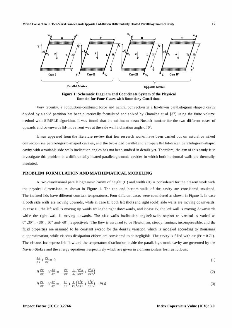
Figure 1: Schematic Diagram and Coordinate System of the Physical
Domain for Four Cases with Boundary Conditions
Very recently, a conduction-combined force and natural convection in a lid-driven parallelogram shaped cavity
divided by a solid partition has been numerically formulated and solved by Chamkha et al. [37] using the finite volume
method with SIMPLE algorithm. It was found that the minimum mean Nusselt number for the two different cases of
upwards and downwards lid-movement was at the side wall inclination angle of 0o.
It was appeared from the literature rev iew that few research works have been carried out on natural or mixed
convection ina parallelogram-shaped cavities, and the two-sided parallel and anti-parallel lid-driven parallelogram-shaped
cavity with a variable side walls inclination angles has not been studied in details yet. Therefore; the aim of this study is to
investigate this problem in a differentially heated parallelogrammic cavities in which both horizontal walls are thermally
insulated.
PROBLEM FORMULATION AND MATHEMATICAL MODELING
A two-dimensional parallelogrammic cavity of height (H) and width (H) is considered for the present work with
the physical dimensions as shown in Figure 1. The top and bottom walls of the cavity are considered insulated.
The inclined lids have different constant temperatures. Four different cases were considered as shown in Figure 1. In case
I, both side walls are moving upwards, while in case II, both left (hot) and right (cold) side walls are moving downwards.
In case III, the left wall is moving up wards while the right downwards, and incase IV, the left wall is moving downwards
while the right wall is moving upwards. The side walls inclination angle(Φ)with respect to vertical is varied as
0° ,30° , - 30° , 60° and- 60°, respectively. The flow is assumed to be Newtonian, steady, laminar, incompressible, and the
flu id properties are assumed to be constant except for the density variation which is modeled according to Boussines
q approximation, while viscous dissipation effects are considered to be negligible. The cavity is filled with air (Pr = 0.71).
The viscous incompressible flow and the temperature distribution inside the parallelogrammic cavity are governed by the
Navier–Stokes and the energy equations, respectively which are given in a dimensionless form as follows:
(1)
(2)
(3)
18 Mohammed Yousif Jabbar
www.iaset.us edi [email protected]
(4)
The governing equations are transformed into dimensionless forms under the following non -dimensional
variables:
(5)
The previous dimensionless numbers are defined as:-
(6)
The governing parameters in this problem is Richards on number, Ri =Gr/Re2, which characterizes the relative
importance of buoyancy to forced convection. To vary Richardson number, Grash of number is fixed at Gr =104 while
changing Reynolds number through the plate velocity VP(10 ≤ Re ≤ 1000). The calculations are done with Reynolds
number identical at both sides of the cavity. Investigations through the cavity are made for ranges of the Richardson
number from 0.01 to 100. Two-sided lid-driven cavity is analyzed according to the direction of moving plate, as shown in
Figure 1. The rate of heat transfer is expressed in terms of average Nusselt number ( ) as fo llows :
Φ
(7)
Boundary Conditions
The boundary conditions which are used in the present study, can be arranged as follows:
The top wall of the parallelogrammic cavity is considered adiabatic, so that:
Y= Φ ,
, U = V = 0 (8)
The bottom wall of the parallelogrammic cavity is considered adiabatic, so that:
Y=0,
, U = V=0 (9)
The left inclined side wall is maintained at a uniform hot temperature (TH), so that:
0≤X≤ Φ Φ Φ Φ (01)
The right inclined side wall is maintained at a uniform co ld temperature(TC), so that:
1 ≤X≤ 1+ Φ , Φ Φ Φ (10)
NUMERICAL SCHEME AND VALIDATION
Continuity, Navier–Stokes and energy Eqs.(1) through (4) with corresponding boundary conditions given in
Eqs. (8-11) are solved using the finite volume approach [38, 39]. The diffusion terms are approximated by a second order
central difference scheme which gives a stable solution. Furthermore, a second order upwind differencing scheme is
adopted for the convective terms. The finite volume method along with the SIMPLE algorithm is applied to transfer the
partial differential equations to algebraic relat ions. Then, the SIP (Strongly Implicit Procedure) algorithm is used to solve
the obtained algebraic equations. The present code utilizes the collocated variable arrangement. The iterative solution is
Mixed Convection in Two-Sided Parallel and Opposite Lid-Driven Differentially Heated Parallelogrammic Cavity 19
Impact Factor (JCC): 3.2766 Index Copernicus Value (ICV): 3.0
continued until the residuals for all computational cells became less than 10-6
for all dependent variables. The description
of this solution method is given very well in Ferzinger and Peric [40], and the details are not given here for brevity. In the
present work, eight combinations (40 x 40, 50 x 50, 60 x 60, 70 x 70, 80 x 80, 100 x 100, 120 x 120 and 150 x 150) of
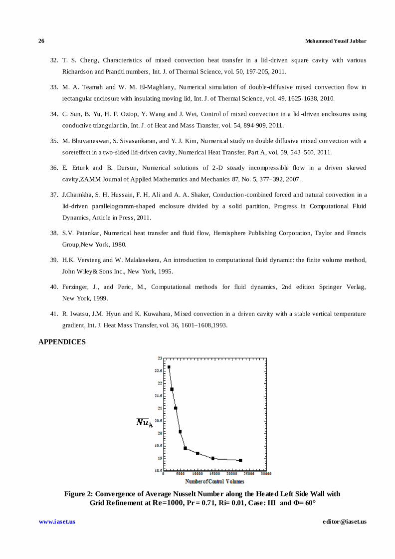
non-uniform grids are used to test the effect of grid size on the accuracy of the predicted results. Figure 2 shows the
convergence of the average Nusselt number , at the left heated side wall of the parallelogram-shaped enclosure with
grid refinement. It is observed that the grid independence is achieved with the combination of (120x120) control volumes,
where there is insignificant change in the average Nusselt number with the improvement in finer grid. The agreement
is found to be excellent, which verifies the present computations indirectly.
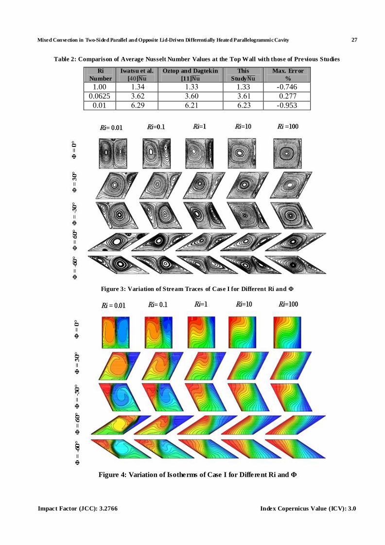
The validation of present computer code has been verified for the mixed convection in a lid-driven cavity with a
stable vertical temperature gradient problem by Iwatsu et al. [41] and Oztop and Dagtekin [11]. As can be seen from
Table 2, there is a good agreement for average Nusselt numbers at the top wall obtained in the present study when
compared to those of [41&11].
RESULTS AND DISCUSSIONS
Mixed convection in a parallelogrammic cavity whose left and right walls move in same direction
(parallel mot ion) or opposite (anti-parallel mot ion) direction with a constant velocity, is the problem analyzed in the
present study. The boundary conditions for parallel and anti parallel walls mot ion cases are shown in Figure 1.
Parallel Walls Motion
For case I, Figure 3 depicts the stream traces obtained for five different values of Richardson numbers
(Ri=0.01, 0.1, 1, 10 and 100). In addit ion, the cavity inclination angle is varied as (Φ=0o, 30
o, 60
o, -30
o, and -60
o). Here, the
left and right walls move upwards, and the line somewhere parallel to them is in the same d irection with same velocity.
At Ri=0.01 and Φ=0°, the stream traces form two primary quazi-symmetrical vortices, and another two secondary vortices
near the top horizontal wall o f the cavity. It is noted that for the left primary vortex, the forces due to moving left lid and
buoyancy act in the same clock-wise direction (aiding). Vise verse, the lager force due to moving right lid and small
buoyancy force act in opposite directions (opposing). As the Richardson number increases (Ri=0.1, 1, 10 and 100),
the natural convection plays a dominate role, making the left primary vortex to grow up and continues to increase in size
and fill almost the cavity. The right primary vortex is gradually eliminated, because the natural convection opposes its
circulat ion, and the left dominant vortex compresses it to the right wall. Then, the right vortex becomes very thin at
Ri=100, and the two secondary vortices are disappeared with the first step of increasing of Richardson number (Ri=0.1).
When Ri=0.01 and Φ=30o, the two primary vortices are existed too, but the left primary vortex occupies most of the cavity
if it is compared with the same case of Φ=0°. The expansion of the left primary vortex is formed as a result of increasing of
inclination angle then, it pushed the right primary vortex toward the upper right corner. With the increasing of
Ri=0.1, 1, 10 and 100, the expansion of the left primary vortex continues generally but at Ri=10 a nd 100, the right primary
eliminating vortex begins to shrink into two small vort ices at the upper acute and lower obtuse right angles, respectively.
With further increase in inclination angle, Φ=60° and at Ri=0.01, it is noted that the two new small and weak vortices are
appeared and distributed above and under the left large vortex. With the increasing in Ri=0.1, 1, 10 and 100, the two small
vortices are disappeared, the left primary vortex remained dominant too, and the right vortex is eliminated and pre sented to
the upper right corner but doesn’t shrink into two vortices as that happened in the previous step of Φ=30o.

20 Mohammed Yousif Jabbar
www.iaset.us edi [email protected]
The phenomenon is completely reversed when Φ=-30o and Φ=-60
o at Ri=0.01. Here, the right primary vortex
becomes dominant, while the left was dominant when Φ=30o and Φ=60
o. At the same point of comparison, when the
Richardson number continues to increase, the right primary vortex becomes gradually smaller and presen ted downwards to
the right acute bottom angle at Ri=100. The right eliminating vortex doesn’t shrink into two small vortices as that
happened in the right primary vortex when Φ=30o.
The isotherms for mixed convection with different values of Richardson number and Φ are shown in Figure 4,
for case I, lower value of Ri=0.01 with Φ=0o, the same two primary vortices that seen in the stream traces are found here
but in isotherms form. Implying that the flu id is heated from the hot wall on the left and cooled by the cold wall on the
right. Then, at this Richardson number (Ri=0.01), the forced convection implies to dominate over the natural convection.
This heat transfer phenomenon can be noticed form a quasi-symmetrical and steeper thermal grad ients between
two counter-vortices, and there are no isotherms penetration or observed on the core of each vortex. As the Richardson
number increases (Ri=0.1), the isotherms distorted and compressed towards the cold side wall and begin to penetrate
towards the core of the cavity. The isotherms patterns indicate that the energy transfer through the cavity becomes similar
to that of pure natural convection at Ri=1, 10 and 100. As well as, the isotherms nearly be horizontal in the central region
of the cavity. This means, the heat transfer through the cavity central region main ly occurs by conduction. As the wall
inclination angle Φ increases to 30o, an earlier highly compressed isotherm is seen toward the right wall when
Ri=0.01 and 0.1 and the forced convection is dominant. Further increases in Richardson number (Ri=1, 10 and 100) make
the heat transfer dominated by the natural convection. When Φ=60o, the isotherms have the same behavior of Φ=30
o, but at
Ri=10 and 100, the distribution of the isotherms being nearly parallel one to each other, implies basically that the cavity is
in a quasi-conduction domain.
The main difference between the isotherms of Φ=30o and Φ=-30
o, Φ=60
o and Φ=-60
o, are the isotherms clustered
towards the hot left wall instead of the cold right wall, and the same methods of heat transfer (fo rce and natural) convection
and conduction are repeated.
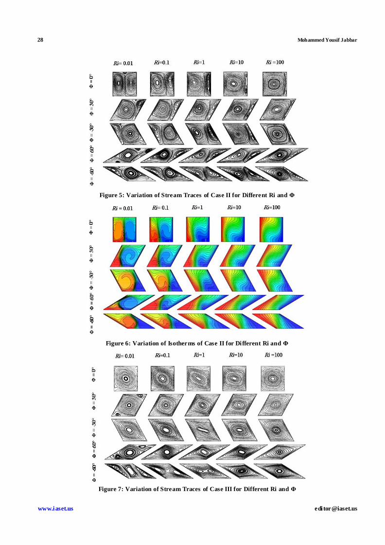
For case II, this is the case where both lid-driven walls move downwards in which the opposing forces of
buoyancy and shear are on the left, and the aiding fo rces are on the right. Therefore, it is expected that, the main circulation
occurs on the right of the cavity. Stream- traces and isotherms for Richardson number from 0.01-100 and Φ=0o-60
o and
Φ=0o- (-60
o), are presented in Figures (5 & 6). It is very clear from the stream traces and isotherms contours that they don’t
change so much, and all events that take place in case I, are inversely repeated in case II.
Opposite Walls Motion
Figures (7-10) give the obtained stream traces and isotherms patterns. Here the left and right walls move in
opposite direction along the line somewhere parallel to them with the same velocity.
For case III, the left wall moves upwards, and the right wall moves downwards for Ri=0.01 -100 and Φ=0°-60°
and Φ=0°- (-60°), as shown in Figure 7. For Ri=0.01 and Φ=0o, a single primary large vortex centered at the geometric
center of the cavity is formed. It is noted that the forces due to moving lids and buoyancy act in the same (aid ing) direction.
In addition, the circulation is clockwise and some perturbations are seen in stream traces in the upper right and lower left
corners due to impingements of the fluid to the horizontal walls. Even if the Richardson number increases (0.1 -100),
the perturbations at the upper right and lower left corners are gradually diminished, and circu lations become stronger, more
Mixed Convection in Two-Sided Parallel and Opposite Lid-Driven Differentially Heated Parallelogrammic Cavity 21
Impact Factor (JCC): 3.2766 Index Copernicus Value (ICV): 3.0
uniform and s mother. Similar phenomenon has been observed with two side lid -driven cavity in the literature by Oz top
and Dagtekin [11], Mahapatra et al. [12] and Perumal and Dass [23]. When the side wall angle increases to 30o, the empty
space is filled with two secondary anti-clockwise vortices near the top right and bottom left corners of the cavity.
Then, when Φ=60o, another third clockwise very small vortex is seen at the left acute angle. As the Richardson number is
increased (0.1-100) for Φ=30° and 60°, the two anti-clockwise and the third clockwise vortices are disappeared, and the
stream traces patterns become stronger, smoother and more uniform, especially at Ri=100. At Φ=-30o and Ri=0.1-100,
this case is similar to the case when Φ=0o, and the stream traces don’t change so much. But, for low Ri=0.01, the denoted
perturbation is less than that when Φ=0o.
For lower Richardson number (Ri=0.01) and Φ=-60o, a new behavior is appeared, the forced convection is
dominant, and strong circulations result in with a three midd le, left and right vortices. The left and right vortices induced
because of moving lids compresses the middle vortex induced due to buoyancy. Thus, all three vortices generated are
almost in same size. When the Richardson number increases (0.1 -100), the natural convection begins to dominate
generally, which is reflected by the increased size of the middle vortex and compression in the two (left and right) vortices
near to both and format ion of a single large clockwise vortex which occupies most of the cavity at Ri=100. It is also
observed (Figure 8, Ri=0.01 and Φ=0o) that the single primary vortex is repeated but in isotherms form.
And, the temperature distribution decreases from the lower to upper of the left hot wall and from upper to lower of the
right cold wall. In what concerns heat transfer, the isotherms show that heat is extracted from the lower left hot wall and
reaches the right cold wall along its length.
The single large primary vortex observed on the stream trace is also observed on the isotherms. Here, the
isotherms are also found to be non-symmetric, showing fo rced convection dominant heat transfer. It is very important to
observe that the effect of the buoyancy force on the isotherms is very clear as Richardson number increases from 0.1 to
100, and a thinner layer of isotherms is near the right vertical wall. This means high heat transfer occurs compared to other
cases, particularly when both natural and forced convection are of the same order. However, the isotherms patterns
corresponding to that of pure natural convection and horizontal isotherms in the core of the cavity indicate that the heat is
transferred like that of conduction. As wall inclination angle increases to 30o, -30
o and 60
o, there is no dramatic change
takes place, only the isotherms patterns distorted to the left or to the right according to the cavity inclination angles.
But, at Φ=60o, a symmetrical behavior about the short diagonal is clearly seen for all values of Richardson number.
This leads to conclude that the mixed convection is appeared earlier here and to be dominant.
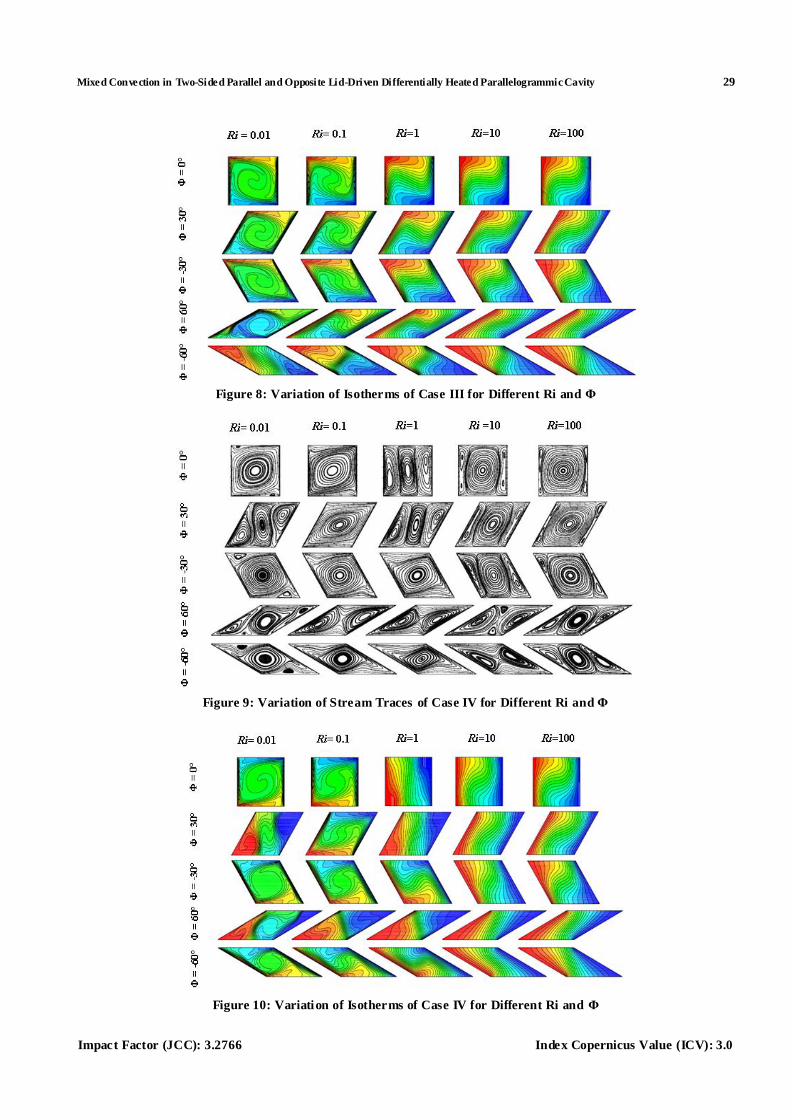
For case IV, Figure (9-10), the left hot wall moves downwards and the right cold wall moves upwards.
The stream traces at Ri=0.01 and Φ=0o illustrate that the strength of lid anti-clockwise circulation is larger than that of
buoyancy clockwise circulation. The most area of the cavity occupied by the primary anti-clockwise circulation and the
two secondary small clockwise vortices at the upper left and lower right corners of the cavity. As Richardson number
increases to 0.1, the two secondary clockwise vortices are disappeared as a result of buoyancy effect. In addition, at Ri=0.1
and Φ=0o, some perturbation is seen in stream traces in the upper left and lower right corners due to impingement of the
flu id to the horizontal walls. With further increases in Richardson number (1 to 100), the new behavior that appeared in
case III when Ri=0.01 and Φ=-60o is again repeated here. Hence, the primary anti-clockwise vortex is divided into three
identical vortices, left, right and middle. As mentioned before, the left anti-clockwise vortex is formed as a result of
opposing of force and natural convection. Vise verse, the aiding of force and natural convection result in a right
22 Mohammed Yousif Jabbar
www.iaset.us edi [email protected]
anti-clockwise vortex. Mean while, the middle vortex is generated due to buoyancy force (natural convection). Thus, the
middle vortex increases in size with the increase in Richardson number, then presses the left and right vortices to the left
hot and right cold walls, respectively. This leads to form a large primary vortex fills almost the cavity and a very thin left
and right vortices, at Ri=100.
Because of the reversed circulations were appeared in case IV as compared with case III, the same isotherms
contours that appeared in case III are inversely repeated here (case IV), Figure 10 doesn’t change so much. Only,
when Ri=1 and Φ=0o and 30
o, a thicker layer o f isotherms are clustered to the top right vertical wall and decreased from
the top to bottom. The isotherms patterns forming flatter vertical lines indicate that the heat transfer assumed that of pure
conduction in the vertical mid -plan. When Ri=0.01 and Φ=30o, the isotherms are pressed and clustered towards the core of
the cavity more than the isotherms of the previous same case, vise verse that happened when Ri=0.01 and Φ=0o of case IV.
Generally, the isotherms patterns in case IV is flatter than that of case III when Ri=0.01 -0.1, the forced convection is
dominant and to be natural for Ri=1-100.
Heat Transfer Characteristics
According to the lid upwards or downwards movement, the local Nusselt number (Nu y) versus the vertical
distance (Y) can be analyzed as fo llows;
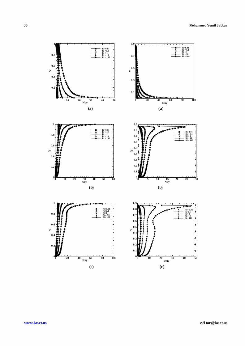
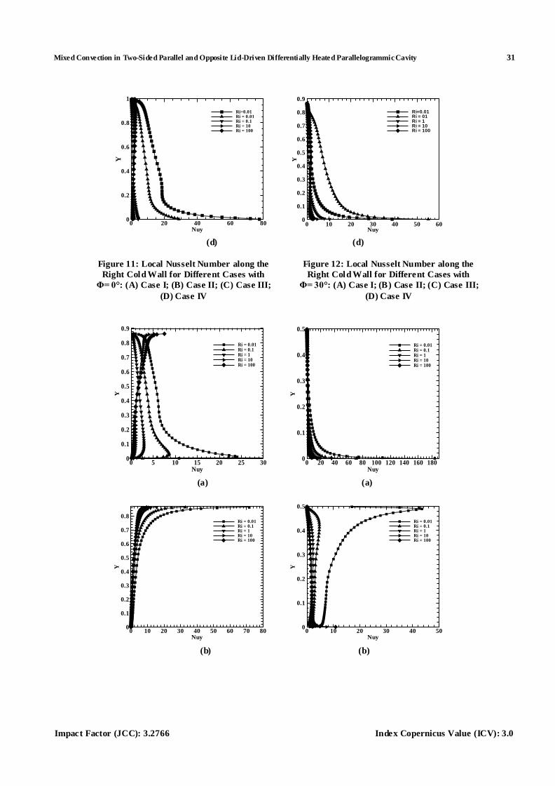
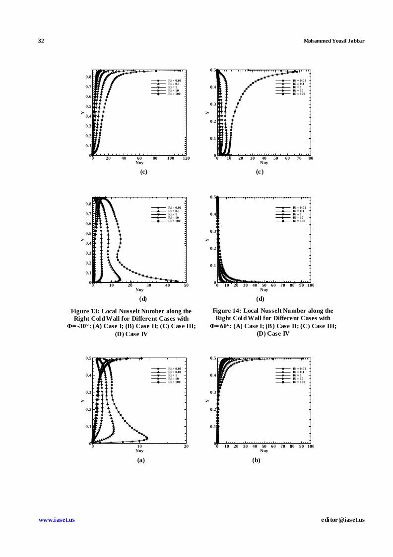
When the right cold wall moves upwards (case I and IV), Figures (11 a& d), it is very obvious, due to the forced
convection affecting negatively on the heat transfer here, the local Nusselt number is decreasing from the bottom to top
along the right cold wall fo r a given Richardson number. Then, we can say the Nusselt number is a decreasin g function of
Richardson number. At high Richardson numbers, the variation of Nusselt number is negligibly small because of the
dominant natural convection. From Figures (12 and 14), (a & d) with increasing the positive value of wall inclination
angle, a similar trend to that of Figures (11 a & d) with reduced local Nusselt number at different Richardson number has
been observed. A similar behavior has been seen in the literature by Oztop and Dagtekin [11]. But, when the value of
sidewall inclination angle decreases negatively, Figures (13 and 15), (a & d), for Ri=0.01 and 0.1, the variation of the local
Nusselt number is complex and has a maximum and min imum points due to the effect of the primary and secondary
vortices on the surfaces, especially for the forced convection dominant flow (Ri=0.01). The maximum local Nusselt
number as a result of impingement of the flu id on hot or cold surfaces, then the thermal boundary layer is grown up.
The min imum local Nusselt number corresponds to the surface when the detachment of the thermal boundary layer occurs.
It should be noted that for Ri> 0.1, the variation of Nusselt number in the negative decrease of sidewall inclination angle
for a given Richardson number is bigger than that of the positive increase because of the dominated forced convection.
When the right cold wall moves downwards (case II and III). Figures (11, 12 and 14), (b & c) for the positive increases and
Figures (13 and 15), (b & c), for negative decreases wall inclination angle, it is very clear that all behaviors of the local
Nusselt number are inversely repeated when the right cold wall moves upwards. A similar behavior has been seen in the
literature by Cheng and Liu [31].
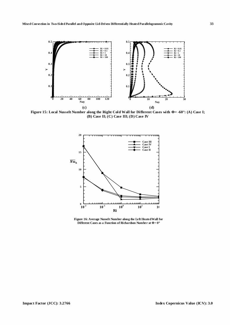
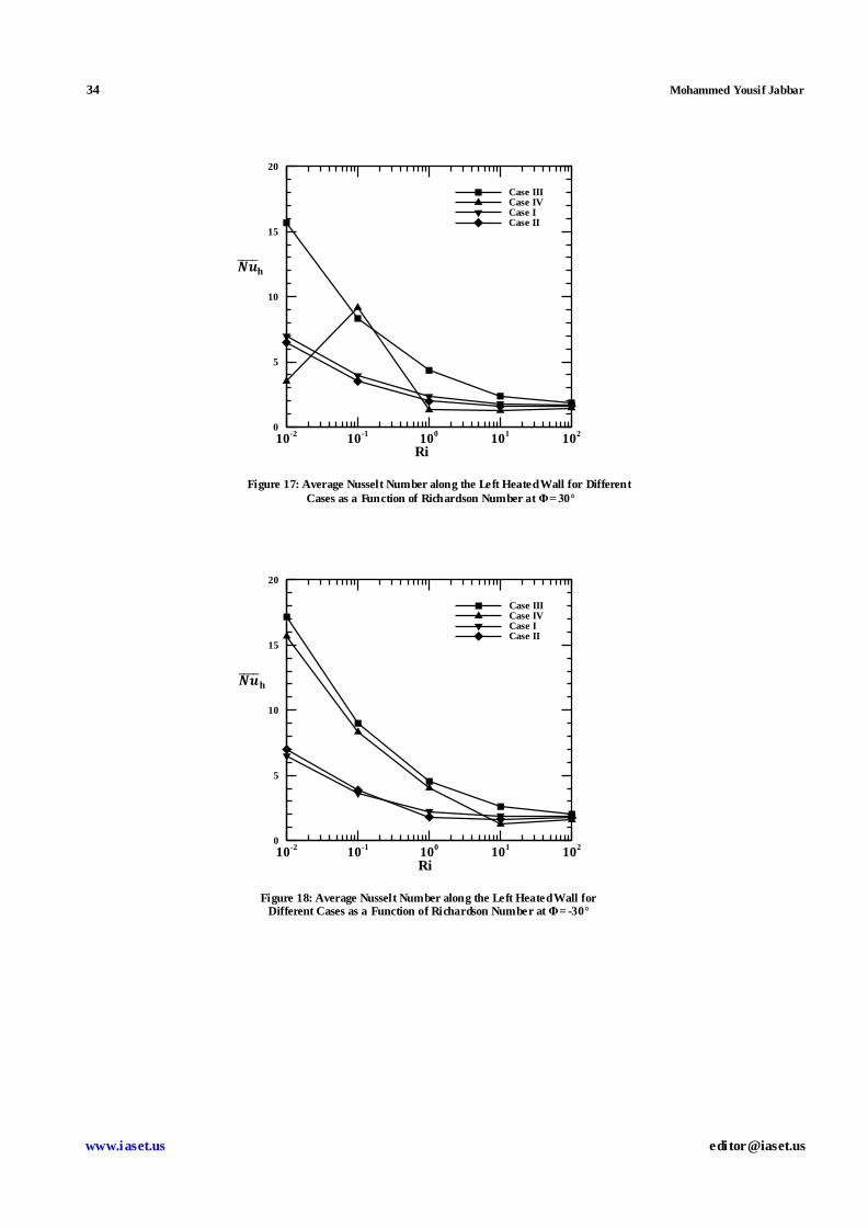
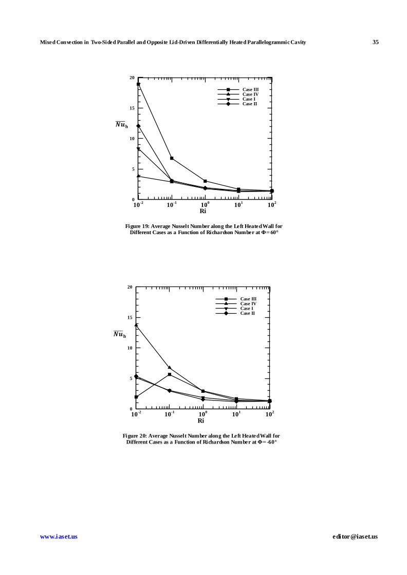
Finally, the effect of decreasing and increasing of the average Nusselt number with increasing of Richardson
number along the left heated wall for different cases of study are presented in Figures (16-20). We should note that for
10≤Ri≤100, the variation of the average Nusselt number is negligib ly small because of the dominant natural convection.
Generally, it has been observed that for Ri<1, the forced convection is the dominated regime, Ri>1 is th e natural
convection dominated regime and Ri=1 is the mixed one for different values of wall inclination angle. But, in Figure 17,
Mixed Convection in Two-Sided Parallel and Opposite Lid-Driven Differentially Heated Parallelogrammic Cavity 23
Impact Factor (JCC): 3.2766 Index Copernicus Value (ICV): 3.0
for case IV, Φ=30°, and Figures 20, for case III,Φ=-60°, the average Nusselt number has the minimum value in these cases
at Ri=0.0, this is due to the fluid which is relatively stagnant at the bottom and top of the left heated wall, respectively. We
can see that for Ri<1, the maximum average Nusselt number is 17.2 atΦ=-30° (case III), and the min imum is 4.0 at Φ=60°
(case IV), for Ri=1, the maximum is 5.0 at Φ=0, 30° and -30° (case III), and the minimum is 1.0 at Φ=0° and 30° (case IV)
and when Ri>1, the average Nusselt number is between 1.0 and 2.0. Generally, the maximum average Nusselt number
along the left heated wall is 17.2 at Φ=-30° and Ri=0.01 (case III), and the maximum local Nusselt number along the right
cold wall is 180 at Φ=60o and Ri=0.01 (case I).
CONCLUSIONS
Parallelogrammic shaped cavity is very attractive to build more complex and complete structures that gives a
good heat transfer performance. The present study deals mainly with parallelogrammic cavities filled with air. It has been
concerned with the numerical modeling of mixed convection in two sided lid -driven differentially heated cavities. It has
been done for four different cases described by the direction of sliding of vertical or inclined walls. The governing
parameters are, Richardson number (Ri) and sidewalls inclination angle (Φ), which describe the heat transfer regime in
mixed convection. From the results of the present investigation, the conclusions can be made as follows:
Commonly, the Richardson number has a greater effect on the heat transfer phenomenon. For Ri<1, the forced
convection is dominated on flow and heat transfer, for Ri>1, the natural convection is dominated, then for Ri=1,
the two regimes are seen (mixed convection). But, at case III, because of greater shear force effect induced by the
greater negative inclination angle (Φ) is added to the buoyancy force, then unusual behavior is s een,
at Ri=0.01 and Φ=-60°, Figure 7, an earlier mixed convection regime is started instead of forced convection.
When the direction of the two moving walls is the same, the heat transfer is reduced and if they are moving in
opposite direction, it is enhanced.
Generally, the average Nusselt number along the left heated wall decreases with increasing values of Richardson
number for all values of side walls inclination angles.
It is found that the local Nusselt number along the right cold wall is a decreasing function for cases I and IV,
and an increasing function for cases II and III, for different values of sidewall inclination angle.
For the positive increase in the value of (Φ), the maximum local Nusselt number for the right cold wall is
predicted to be 180 at Φ=60° (case I), and the min imum is to be 25 at Φ=30° (case II). But, for the negative
decrease of (Φ), the maximum local Nusselt number fo r the right cold wall is to be 117 at Φ=-60° (case III),
and the minimum is 12 at Φ=-60° too but for case I. In general, the maximum local Nusselt number for the
upward lid movements of the right cold wall is 180 at Φ=60° (case I), and the minimum is 12 at Φ=-60° (case I).
Then, the positive values of (Φ) cause a greater increases in local Nusselt number than the same negative values
of (Φ).
It is clearly seen that the maximum average Nusselt number along the left heated wall is predicted to be at Φ=60o,
(Ri=0.01 and case III), and the min imum is at Φ=-60°,(Ri=0.01 and case IV). Generally, for all values of Φ except
at Φ=-60°, case III takes almost the greatest values of average Nusselt number with the increasing of Richardson
number.
24 Mohammed Yousif Jabbar
www.iaset.us edi [email protected]
REFERENCES
1. O. Aydenand Wen-Jei Yang, Mixed convection in cavities with a locally heated lower wall and moving side wall,
Numerical Heat Transfer, Part A, vol. 37, 695-710, 2000.
2. Hiroshi Nakamura and Yutaka Asako, Heat transfer in parallelogrammic shaped enclosure, Bulletin of JSME,
vol. 23, No. 185, 1827-1834, 1980.
3. Yutaka Asako and Hiroshi Nakamura, Heat transfer in parallelogrammic shaped enclosure, Bulletin of JSME,
vol. 25, No. 207, 1412-1418, 1982.
4. Yutaka Asako and Hiroshi Nakamura, Heat transfer in parallelogrammic shaped enclosure, Bulletin of JSME,
vol. 27, No. 228, 1144-1151, 1984.
5. D. Naylor and P. H. Oosthuizen, A numerical study of free convection heat transfer in a parallelogram-shaped
enclosure, International Journal of Numerical Methods for Heat & Flu id Flow, vol. 4, 553-559, 1994.
6. V. A. Costa, Double diffusive natural convection in parallelogrammic enclosures, Int. J. of Heat and Mass
Transfer, vol. 47, 2913-2926, 2004.
7. V. A. F. Costa, Double diffusive natural convection in parallelogrammic enclosures filled with fluid -saturated
porous media, Int. J. of Heat and Mass Transfer, vol. 47, 2699-2714, 2004.
8. J. M. G. D. Maria, A. Bairi and V. A. F. Costa, Empirical correlat ion at high ra for steady -state free convection in
2d air-filled parallelogrammic enclosures with isothermal discrete heat sources, Int. J. of Heat and Mass Transfer,
vol. 53, 3831-3838, 2010.
9. A. Bairi, J. M. G. D. Maria and N. Laraqi, Transient natural convection in parallelogrammic enclosures with
isothermal hot wall. experimental and numerical study applied to on -board electronics, Applied Thermal
Engineering, vol. 30, 1115-1125, 2010.
10. H. C. Kuhlmann, S. Albensoeder and C. Blohm, Flow instabilit ies in the two-sided lid-driven cavity,
12th
International Couette-Taylor Workshop, September 6-8, 2001,Evanston, USA.
11. H. F. Oztopand I. Dagtekin, Mixed convection in two-sided lid-driven differentially heated square cavity,
Int. J. of Heat and Mass Transfer, vol. 47, 1761-1769, 2004.
12. S. K. Mahapatra, P. Nada and A. Sarkar, interaction of mixed convection in two-sided lid-driven differentially
heated square enclosure with radiation in presence of participating medium, Heat and Mass Transfer,
vol. 42, 739-757, 2006.
13. W. J. Luo and R. J. Yang, Multip le fluid flow and heat transfer solutions in two-sided lid-driven cavity, Int. J. of
Heat and Mass Transfer, vol. 50, 2394-2405, 2007.
14. A. Al-Amiri, K. Khanafer, J. Bull and I. Pop, Effect of sinusoidal wavy bottom surface on mixed convection heat
transfer in alid-driven cavity, Int. J. of Heat and Mass Transfer, vol. 50, 1771-1780, 2007.
15. P. Shah, B. Rovagnati, F. Mashayek and G. B. Jacobs, Subsonic compressible flow in two -sided lid-driven cavity.
part i: equal walls temperatures, Int. J. o f Heat and Mass Transfer, vol. 50, 4206-4218, 2007.
Mixed Convection in Two-Sided Parallel and Opposite Lid-Driven Differentially Heated Parallelogrammic Cavity 25
Impact Factor (JCC): 3.2766 Index Copernicus Value (ICV): 3.0
16. P. Shah, B. Rovagnati, F. Mashayek and G. B. Jacobs, Subsonic compressible flow in two-sided lid-driven cavity.
part ii: unequal walls temperatures, Int. J. o f Heat and Mass Transfer, vol. 50, 4219-4228, 2007.
17. H. F. Oztop, C. Sun and B. Yu, Conjugate-mixed convection heat transfer in a lid-driven enclosure with thick
bottom wall, Int. Communications in Heat and Mass Transfer, vol. 35, 779-785, 2008.
18. E. Wahba, Bifurcat ion phenomena for two -sided non-facing lid-driven cavity flow, wseas international conference
on engineering mechanics, structures, Engineering Geology(EMESEG '08), July 22-24, 2008,Heraklion, Crete
Island, Greece.
19. E. M. Wahba, Multip licity of states for two-sided and four-sided lid-driven cavity flows, Computers and Fluids,
vol. 38, 247-253, 2009.
20. D. Z. Noor, P. R. Kanna, M. Chern, Flow andheat transfer in a driven square with double-sided oscillating lids in
anti-phase, Int. J. of Heat and Mass Transfer, vol. 52, 3009-3023, 2009.
21. N. Ouertatani, N. B. Cheikh, B. B. Beya, T. Lili and A. Campo, Mixed convection in a double lid -driven cubic
cavity, Int. J. of Thermal Science, vol. 48, 1265-1272, 2009.
22. T. Basak, S. Roy, S. K. Singh and I. Pop, Analysis of mixed convection in a lid-driven porous square with linearly
heated side walls, Int. J. of Heat and Mass Transfer, vol. 53, 1819-1840, 2010.
23. D. A. Perumal and A. K. Dass, Simulation of Incompressible Flows in Two-Sided Lid-Driven Square Cavities.
Part I-FDM, CFD Letters, vol. 2(1), 13-24, 2010.
24. D. A. Perumal and A. K. Dass, Simulat ion of incompressible flows in two-sided lid-driven square cavities. Part II-
LBM, CFD Letters, vol. 2(1), 25-38, 2010.
25. D. A. Perumal and A. K. Dass, Multiplicity of steady solutions in two-dimensional lid-driven cavity flows by
Lattice Boltzmann method, Computer and Mathematics with Applications, vol. 61, 3711-3721, 2011.
26. V. Sivakumar, S. Sivasankaran, P. Prakash and J. Lee, Effect of heating location and size on mixed convection in
lid -driven cavit ies, Computer and Mathematics with Applicat ions, vol. 59, 3053-3065, 2010.
27. E. B. Ogut, Mixed convection in an inclined lid-driven enclosure with a constant flux heater using differential
quadrature (DQ) method, Int. J. of Physics Science, vol. 5(15), 2287-2303, 18 November, 2010.
28. S. Saha, G. Saha and N. Hasan, Mixed convection in a lid-driven with an internal heat source, Proceeding of the
13th
Annual Paper Meet, 25 September, 2010, Dhaka.
29. M. N. Hasan, N. Hasan, Md. Q. Islam, S. Saha and G. Saha, Effect of internal heat generation or absorption on
mixed convection characteristics in a tilted lid-driven square enclosure, Proceeding of the 13th
Annual Paper
Meet, 25 September, 2010, Dhaka.
30. S. Sivasankaran, V. Sivakumar and P. Prakash, Numerical study on mixed convection in a lid -driven cavity with
non-uniform heating on both side walls, Int. J. of Heat and Mass Transfer, vol. 53, 4304-4315, 2010.
31. T. S. Cheng and W. H. Liu, Effect of temperature gradient orientation on the characteristics of mixed convection
flow in a lid-driven square cavity, Computers and Fluid, vol. 39, 965-978, 2010.
26 Mohammed Yousif Jabbar
www.iaset.us edi [email protected]
32. T. S. Cheng, Characteristics of mixed convection heat transfer in a lid -driven square cavity with various
Richardson and Prandtl numbers, Int. J. of Thermal Science, vol. 50, 197-205, 2011.
33. M. A. Teamah and W. M. El-Maghlany, Numerical simulation of double-diffusive mixed convection flow in
rectangular enclosure with insulating moving lid, Int. J. of Thermal Science, vol. 49, 1625-1638, 2010.
34. C. Sun, B. Yu, H. F. Oztop, Y. Wang and J. Wei, Control of mixed convection in a lid -driven enclosures using
conductive triangular fin, Int. J. of Heat and Mass Transfer, vol. 54, 894-909, 2011.
35. M. Bhuvaneswari, S. Sivasankaran, and Y. J. Kim, Numerical study on double diffusive mixed convection with a
soreteffect in a two-sided lid-driven cavity, Numerical Heat Transfer, Part A, vol. 59, 543–560, 2011.
36. E. Erturk and B. Dursun, Numerical solutions of 2-D steady incompressible flow in a driven skewed
cavity,ZAMM Journal of Applied Mathematics and Mechanics 87, No. 5, 377–392, 2007.
37. J.Chamkha, S. H. Hussain, F. H. Ali and A. A. Shaker, Conduction-combined forced and natural convection in a
lid -driven parallelogramm-shaped enclosure divided by a solid partition, Progress in Computational Fluid
Dynamics, Article in Press, 2011.
38. S.V. Patankar, Numerical heat transfer and fluid flow, Hemisphere Publishing Corporation, Taylor and Francis
Group,New York, 1980.
39. H.K. Versteeg and W. Malalasekera, An introduction to computational flu id dynamic: the finite volume method,
John Wiley& Sons Inc., New York, 1995.
40. Ferzinger, J., and Peric, M., Computational methods for fluid dynamics, 2nd edition Springer Verlag,
New York, 1999.
41. R. Iwatsu, J.M. Hyun and K. Kuwahara, Mixed convection in a driven cavity with a stable vertical temperature
gradient, Int. J. Heat Mass Transfer, vol. 36, 1601–1608,1993.
APPENDICES
Figure 2: Convergence of Average Nusselt Number along the Heated Left Side Wall with
Grid Refinement at Re=1000, Pr = 0.71, Ri= 0.01, Case: III and Φ= 60°
Mixed Convection in Two-Sided Parallel and Opposite Lid-Driven Differentially Heated Parallelogrammic Cavity 27
Impact Factor (JCC): 3.2766 Index Copernicus Value (ICV): 3.0
Table 2: Comparison of Average Nusselt Number Values at the Top Wall with those of Previous Studies
Ri
Number
Iwatsu et al.
[01]
Oztop and Dagtekin
[11]
This
Study
Max. Error
%
1.00 03.0 03.. 1.33 -0.746
0.0625 .3.3 .3.1 .3.0 13300
0.01 .336 .330 .33. -0.953
Figure 3: Variation of Stream Traces of Case I for Different Ri and Φ
Figure 4: Variation of Isotherms of Case I for Different Ri and Φ
28 Mohammed Yousif Jabbar
www.iaset.us edi [email protected]
Figure 5: Variation of Stream Traces of Case II for Different Ri and Φ
Figure 6: Variation of Isotherms of Case II for Different Ri and Φ
Figure 7: Variation of Stream Traces of Case III for Different Ri and Φ
Mixed Convection in Two-Sided Parallel and Opposite Lid-Driven Differentially Heated Parallelogrammic Cavity 29
Impact Factor (JCC): 3.2766 Index Copernicus Value (ICV): 3.0
Figure 8: Variation of Isotherms of Case III for Different Ri and Φ
Figure 9: Variation of Stream Traces of Case IV for Different Ri and Φ
Figure 10: Variation of Isotherms of Case IV for Different Ri and Φ
30 Mohammed Yousif Jabbar
www.iaset.us edi [email protected]
(a) (a)
(b) (b)
(c) (c)
Nuy
Y
10 20 30 40 50
0.2
0.4
0.6
0.8
1
Ri=0.01Ri =0.1Ri = 1Ri = 10Ri = 100
Nuy
Y
0 20 40 60 80 100
0.1
0.3
0.5
0.7
0.9
Ri=0.01Ri = 0.1Ri = 1Ri = 10Ri = 100
Nuy
Y
0 10 20 30 40 50 600
0.2
0.4
0.6
0.8
1
Ri=0.01Ri = 0.1Ri = 1Ri = 10Ri = 100
Nuy
Y
0 5 10 15 20 25 300
0.1
0.2
0.3
0.4
0.5
0.6
0.7
0.8
0.9
Ri=0.01Ri = 0.1Ri = 1Ri = 10Ri = 100
Nuy
Y
0 20 40 60 80 1000
0.2
0.4
0.6
0.8
1
Ri=0.01Ri=0.1Ri=1Ri = 10Ri= 100
Nuy
Y
0 10 20 30 40 500
0.1
0.2
0.3
0.4
0.5
0.6
0.7
0.8
0.9
Ri = 0.01Ri=0.1Ri = 1Ri =10Ri = 100
Mixed Convection in Two-Sided Parallel and Opposite Lid-Driven Differentially Heated Parallelogrammic Cavity 31
Impact Factor (JCC): 3.2766 Index Copernicus Value (ICV): 3.0
(d) (d)
(a) (a)
(b) (b)
Nuy
Y
0 20 40 60 800
0.2
0.4
0.6
0.8
1
Ri=0.01Ri = 0.01Ri = 0.1Ri = 10Ri = 100
Nuy
Y
0 10 20 30 40 50 600
0.1
0.2
0.3
0.4
0.5
0.6
0.7
0.8
0.9
Ri=0.01Ri = 01Ri = 1Ri = 10Ri = 100
Nuy
Y
0 5 10 15 20 25 300
0.1
0.2
0.3
0.4
0.5
0.6
0.7
0.8
0.9
Ri = 0.01Ri = 0.1Ri = 1Ri = 10Ri = 100
Nuy
Y
0 20 40 60 80 100 120 140 160 1800
0.1
0.2
0.3
0.4
0.5
Ri = 0.01Ri = 0.1Ri = 1Ri = 10Ri = 100
Nuy
Y
0 10 20 30 40 50 60 70 800
0.1
0.2
0.3
0.4
0.5
0.6
0.7
0.8Ri = 0.01Ri = 0.1Ri = 1Ri = 10Ri = 100
Nuy
Y
0 10 20 30 40 500
0.1
0.2
0.3
0.4
0.5
Ri = 0.01Ri = 0.1Ri = 1Ri = 10Ri = 100
Figure 11: Local Nusselt Number along the
Right Cold Wall for Different Cases with
Φ= 0°: (A) Case I; (B) Case II; (C) Case III;
(D) Case IV
Figure 12: Local Nusselt Number along the
Right Cold Wall for Different Cases with
Φ= 30°: (A) Case I; (B) Case II; (C) Case III;
(D) Case IV
32 Mohammed Yousif Jabbar
www.iaset.us edi [email protected]
(c) (c)
(d) (d)
(a) (b)
Nuy
Y
0 20 40 60 80 100 1200
0.1
0.2
0.3
0.4
0.5
0.6
0.7
0.8Ri = 0.01Ri = 0.1Ri = 1Ri = 10Ri = 100
Nuy
Y
0 10 20 30 40 50 60 70 800
0.1
0.2
0.3
0.4
0.5
Ri = 0.01Ri = 0.1Ri = 1Ri = 10Ri = 100
Nuy
Y
0 10 20 30 40 500
0.1
0.2
0.3
0.4
0.5
0.6
0.7
0.8Ri = 0.01Ri = 0.1Ri = 1Ri = 10Ri = 100
Nuy
Y
0 10 20 30 40 50 60 70 80 90 1000
0.1
0.2
0.3
0.4
0.5
Ri = 0.01Ri = 0.1Ri = 1Ri = 10Ri = 100
Nuy
Y
0 10 200
0.1
0.2
0.3
0.4
0.5
Ri = 0.01Ri = 0.01Ri = 1Ri = 10Ri = 100
Nuy
Y
0 10 20 30 40 50 60 70 80 90 1000
0.1
0.2
0.3
0.4
0.5
Ri = 0.01Ri = 0.1Ri = 1Ri = 10Ri = 100
Figure 13: Local Nusselt Number along the
Right Cold Wall for Different Cases with
Φ= -30°: (A) Case I; (B) Case II; (C) Case III;
(D) Case IV
Figure 14: Local Nusselt Number along the
Right Cold Wall for Different Cases with
Φ= 60°: (A) Case I; (B) Case II; (C) Case III;
(D) Case IV
Mixed Convection in Two-Sided Parallel and Opposite Lid-Driven Differentially Heated Parallelogrammic Cavity 33
Impact Factor (JCC): 3.2766 Index Copernicus Value (ICV): 3.0
(c) (d)
Figure 15: Local Nusselt Number along the Right Cold Wall for Different Cases with Φ= -60°: (A) Case I;
(B) Case II; (C) Case III; (D) Case IV
Nuy
Y
0 20 40 60 80 100 1200
0.1
0.2
0.3
0.4
0.5
Ri = 0.01Ri = 0.1Ri = 1Ri = 10Ri = 100
Nuy
Y
0 10 20 300
0.1
0.2
0.3
0.4
0.5
Ri = 0.01Ri = 0.1Ri = 1Ri = 10Ri = 100
10-2
10-1
100
101
102
0
5
10
15
20
Case IIICase IVCase ICase II
Figure 16: Average Nusselt Number along the Left Heated Wall for
Different Cases as a Function of Richardson Number at Φ= 0°
Ri
34 Mohammed Yousif Jabbar
www.iaset.us edi [email protected]
10-2
10-1
100
101
102
0
5
10
15
20
Case IIICase IVCase ICase II
Figure 17: Average Nusselt Number along the Left Heated Wall for Different
Cases as a Function of Richardson Number at Φ= 30°
Ri
10-2
10-1
100
101
102
0
5
10
15
20
Case IIICase IVCase ICase II
Figure 18: Average Nusselt Number along the Left Heated Wall for Different Cases as a Function of Richardson Number at Φ= -30°
Ri
Mixed Convection in Two-Sided Parallel and Opposite Lid-Driven Differentially Heated Parallelogrammic Cavity 35
www.iaset.us edi [email protected]
10-2
10-1
100
101
102
0
5
10
15
20
Case IIICase IVCase ICase II
Figure 19: Average Nusselt Number along the Left Heated Wall for Different Cases as a Function of Richardson Number at Φ= 60°
Ri
10-2
10-1
100
101
102
0
5
10
15
20
Case IIICase IVCase ICase II
Figure 20: Average Nusselt Number along the Left Heated Wall for Different Cases as a Function of Richardson Number at Φ= -60°
Ri


