Download - 17510578-Opal 090 B-02 15-EN - Agroinform

Operating Instructions
Mounted Reversible Ploughs Opal 090 B
- en -
Item no . 17510578 00/01.15 /
LEMKEN India Agro Equipment Pvt Ltd. Plot No. D-59, MIDC,
Butibori, Nagpur - 441108, Maharashtra, India
Phone: +91 - 7104-305400 Fax: +91 - 7104-305444
E-Mail: [email protected]


1
Dear customer,
Thank you for the trust you have placed in us by purchasing this device. The de-vice can only be used to its full advantage when operated and used properly. When the device was delivered, you will already have been instructed in opera-tion, adjustment and maintenance by your dealer. However, this brief instruction is not a substitute for thorough study of the operating instructions.
These operating instructions will help to familiarise you with the LEMKEN India Agro Equipment Pvt Ldt.device and the options available for using it.
The operating instructions contain important information about how to operate the device safely, properly and efficiently. Following the instructions will help to pre-vent hazards, faults and down times and will increase reliability and service life. Read the operating instructions carefully and attentively before commissioning.
Make sure that the operating instructions are always available at the location where the device is used.
The operating instructions must be read and followed by anyone who is involved in carrying out the following work:
Coupling and uncoupling
Adjustments
Operation
Maintenance and repairs
Troubleshooting, and
Final shutdown and disposal.

2
Spare parts ordering
This device is supplied with a specification listing all assemblies that are relevant for the product. The spare parts list valid for your device includes both those as-semblies relevant to you and those that are not intended for your device. Make sure that you only order spare parts that belong to the assemblies that can be found on your specification or the enclosed print out. When ordering spare parts, state the type designation and serial number of the device. This information can be found on the type plate. Enter this data in the fields below so that it is always to hand.
Type designation:
Serial number:
Remember that you should only use genuine LEMKEN spare parts. Reproduction parts have a negative influence on the function of the device, have a shorter ser-vice life and present risks and hazards that cannot be estimated by LEMKEN India Agro Equipment Pvt Ldt.. They also increase the maintenance costs.
Service and spare parts
Information on service and spare parts is available from your local dealer or our website at www.lemken.com.

Contents
3
CONTENTS
Contents ........................................................................................................................... 3
1 General information .................................................................................................. 8
1.1 Liability ........................................................................................................................... 8
1.2 Guarantee ....................................................................................................................... 8
1.3 Copyright ....................................................................................................................... 9
1.4 Optional accessories .................................................................................................... 9
2 Symbols used in the Operating Instructions ........................................................ 10
2.1 Hazard classes ............................................................................................................ 10
2.2 Information ................................................................................................................... 10
2.3 Environmental protection ........................................................................................... 10
2.4 Indication of passages ................................................................................................ 11
3 Safety measures and precautions ......................................................................... 12
3.1 Target group ................................................................................................................ 12
3.2 Intended use ................................................................................................................ 12
3.3 Safety features of the device ...................................................................................... 13
3.4 Safety and warning signs ........................................................................................... 13
3.4.1 General information ................................................................................................... 13
3.4.2 Position of warning symbols ...................................................................................... 14
3.4.3 Meaning of warning signs .......................................................................................... 14
3.5 Special safety instructions ......................................................................................... 16
3.6 Hazardous areas .......................................................................................................... 17
3.6.1 Hazardous areas during operation of the device ....................................................... 18
3.7 Residual risks .............................................................................................................. 18
3.7.1 Hazard caused by mechanical systems ..................................................................... 18
3.7.2 Hazard caused by hydraulic systems ........................................................................ 19
3.8 Applicable rules and regulations ............................................................................... 19
3.9 Operation on public highways ................................................................................... 19
3.9.1 Lighting system and identification .............................................................................. 19

Contents
4
3.9.2 Requirements of the tractor ....................................................................................... 20
3.9.3 Axle loads .................................................................................................................. 21
3.9.4 Check before departure ............................................................................................. 25
3.9.5 Correct behaviour in road traffic ................................................................................ 26
3.10 Obligation of the operator .......................................................................................... 26
3.11 Operating the device safely ........................................................................................ 27
3.11.1 General information ................................................................................................ 27
3.11.2 Personnel selection and qualifications ................................................................... 28
3.11.3 Hydraulic system .................................................................................................... 28
4 Handing over the Implement .................................................................................. 29
5 Layout and description ........................................................................................... 30
5.1 Overview ...................................................................................................................... 30
5.2 Description ................................................................................................................... 31
5.2.1 Headstock .................................................................................................................. 31
5.2.2 Turnover device ......................................................................................................... 31
5.2.3 Optiquick adjustment system ..................................................................................... 31
5.2.4 Basic frame ................................................................................................................ 31
5.2.5 Depth wheel ............................................................................................................... 31
5.2.6 Plough bodies ............................................................................................................ 32
5.2.7 Additional tools .......................................................................................................... 32
5.2.8 Disc coulters .............................................................................................................. 34
6 Preparations on tractor .......................................................................................... 35
6.1 Tyres ............................................................................................................................. 35
6.2 Lifting rods ................................................................................................................... 35
6.3 Top Link ....................................................................................................................... 35
6.4 Chains and stabilisers of the three-way linkage ....................................................... 35
6.5 Hydraulics .................................................................................................................... 35
6.6 Hydraulic equipment required .................................................................................... 36
7 Preparing the implement ........................................................................................ 37
7.1 General ......................................................................................................................... 37
7.2 Upper control link length ............................................................................................ 37

Contents
5
7.3 Depth wheel ................................................................................................................. 37
7.4 Skimmer ....................................................................................................................... 37
7.5 Setting the outer screw of the Optiquick adjustment centre ................................... 38
7.1 Clearance required for turning ................................................................................... 38
7.2 Three-point connection............................................................................................... 39
8 Attaching the implement ........................................................................................ 40
8.1 Specific safety information ......................................................................................... 40
8.2 General ......................................................................................................................... 40
9 Uncoupling the implement ..................................................................................... 42
9.1 Specific safety information ......................................................................................... 42
9.2 General ......................................................................................................................... 42
10 Driving on public roads .......................................................................................... 44
10.1 Laws and regulations .................................................................................................. 44
11 Operation ................................................................................................................. 45
11.1 Specific safety information ......................................................................................... 45
11.2 Turning the plough frame ........................................................................................... 45
11.3 Setting the front furrow width .................................................................................... 46
11.3.1 General information ................................................................................................ 46
11.3.2 Front furrow width, mechanical ............................................................................... 46
11.4 Setting the tractor/plough pull line ............................................................................ 47
11.5 Angle ............................................................................................................................ 47
11.5.1 General information ................................................................................................ 47
11.5.2 Inclination setting (double-acting) ........................................................................... 48
11.5.3 Inclination setting (single-acting) ............................................................................ 48
11.6 Working depth ............................................................................................................. 49
11.7 DURAL plough body ................................................................................................... 49
11.7.1 Contact angle ......................................................................................................... 49
11.7.2 Working width per body .......................................................................................... 50
11.7.3 Tail Pieces .............................................................................................................. 51

Contents
6
11.8 Skimmers ..................................................................................................................... 52
11.8.1 General................................................................................................................... 52
11.8.2 Working depth ........................................................................................................ 52
11.8.3 Adjusting the projection angle ................................................................................ 52
11.8.4 Lateral position ....................................................................................................... 53
11.8.5 Forwards or backwards .......................................................................................... 53
11.8.6 Trashboard ............................................................................................................. 54
11.9 Sword Coulter .............................................................................................................. 54
11.10 Disc coulters ................................................................................................................ 55
11.10.1 General ............................................................................................................... 55
11.10.2 Working depth ..................................................................................................... 55
11.10.3 Moving the disc coulter forwards or backwards................................................... 56
11.10.4 Disc coulter inclination ........................................................................................ 56
11.11 Depth control wheel .................................................................................................... 57
11.11.1 General ............................................................................................................... 57
11.11.2 Mounting ............................................................................................................. 57
11.12 Working depth adjustment ......................................................................................... 58
11.13 Shearing protection .................................................................................................... 59
12 Put the implement out of operation ....................................................................... 60
12.1 Shutting down the implement in an emergency ....................................................... 60
12.2 Disposal ....................................................................................................................... 60
13 Maintenance and repairs ........................................................................................ 61
13.1 Special safety instructions ......................................................................................... 61
13.1.1 General................................................................................................................... 61
13.1.2 Working under the raised device ............................................................................ 61
13.1.3 Immobilise the implement for maintenance and repairs ......................................... 62
13.1.4 Working on the hydraulics ...................................................................................... 62
13.1.5 Personnel qualifications ......................................................................................... 62
13.1.6 Protective equipment .............................................................................................. 63
13.1.7 Utilised tool ............................................................................................................. 63
13.2 Environmental protection ........................................................................................... 64
13.3 Maintenance intervals ................................................................................................. 64

Contents
7
13.3.1 After the initial start-up (at the latest after 2 hours) ................................................. 64
13.3.2 Daily inspection ...................................................................................................... 64
13.3.3 Weekly inspection .................................................................................................. 65
13.4 Tightening torques ...................................................................................................... 65
13.4.1 General information ................................................................................................ 65
13.4.2 Bolts and nuts made of steel .................................................................................. 66
13.4.3 Wheel bolts and wheel nuts .................................................................................... 66
13.5 Tyre pressure ............................................................................................................... 67
13.6 Check the connections to the tractor ........................................................................ 67
13.6.1 Hydraulic connections ............................................................................................ 67
13.6.2 Electrical connections ............................................................................................. 68
13.6.3 Lubrication chart ..................................................................................................... 69
14 Troubleshooting ...................................................................................................... 70
14.1 Hydraulic equipment ................................................................................................... 70
14.2 Plough intake and depth control, slippage ............................................................... 73
14.3 Miscellaneous .............................................................................................................. 73
15 Technical data ......................................................................................................... 74
15.1 Permissible power range and weight ........................................................................ 74
16 Identification plate .................................................................................................. 75
Index ............................................................................................................................... 76

General information
8
1 GENERAL INFORMATION
1.1 Liability
The "Standard Terms and Conditions of Sales and Delivery" of LEMKEN GmbH & Co. KG, in particular Section IX, shall apply. Liability. In line with the dimensions cited in these conditions the LEMKEN GmbH & Co. KG shall not be held liable for any personal or material damage, when such damage is caused by one or more of the following reasons:
improper use of the device, see also section entitled "Intended use",
non-compliance with the operating instructions and the enclosed safety instruc-tions,
unauthorised changes to the device,
inadequate monitoring of parts which are subject to wear,
maintenance work that has not been conducted properly or in good time,
the use of spare parts that are not original LEMKEN GmbH & Co. KG spare parts,
accidents or damage through outside influences or force majeure
1.2 Guarantee
The "Standard Terms and Conditions of Sales and Delivery" of LEMKEN GmbH & Co. KG shall apply at all times.
The guarantee period shall be one year from the date of receipt of the implement. We shall rectify any implement faults in accordance with the LEMKEN guarantee guidelines.

General information
9
1.3 Copyright
These operating instructions represent a document in terms of the law on unfair competition.
Copyright is retained by
LEMKEN GmbH & Co. KG
Weseler Strasse 5
D-46519 Alpen, Germany
These operating instructions are intended to be used by the user of the imple-ment. They contain texts and drawings which must not be
reproduced,
divulged or
communicated in any other way in whole or in part without the express permis-sion of the manufacturer.
Infringements will result in a claim for damages.
1.4 Optional accessories
LEMKEN implements may be equipped with various accessories. The operating instructions below describe both series components and optional accessories.
Please note: These accessories will vary depending on the type of equipment.

Symbols used in the Operating Instructions
10
2 SYMBOLS USED IN THE OPERATING INSTRUCTIONS
2.1 Hazard classes
The following symbols are used in the Operating Instructions for particularly im-portant information:
DANGER
Denotes an imminent hazard with high risk, which will result in death or severe physical injury, if not avoided.
WARNING
Denotes a possible hazard with medium risk, which could result in death or severe physical injury, if not avoided.
CAUTION
Denotes a low-risk hazard, which could cause light or medium physical injury or property damage, if not avoided.
2.2 Information
Denotes special user tips and other particularly useful or important information for operation and efficient utilisation.
2.3 Environmental protection
Indication of special recycling and environmental protection measures.

Symbols used in the Operating Instructions
11
2.4 Indication of passages
The following symbols are used for particular passages in the operating instruc-tions:
Indicates work steps
Indicates enumerations

Safety measures and precautions
12
3 SAFETY MEASURES AND PRECAUTIONS
General safety instructions for the operator are specified in the chapter entitled «Safety measures and precautions». At the start of some main chapters the safety instructions, which refer to all work to be carried out in this chapter, are listed to-gether. Each safety-relevant work step includes other safety instructions specific to the work step.
3.1 Target group
These operating instructions are restricted exclusively to the use of the device by trained technicians and instructed persons.
3.2 Intended use
The device is manufactured in accordance with state-of-the-art standards and the recognised safety rules. However, the use of the device may result in a risk to life and limb of the user or third parties, or cause damage to the device and other ma-terial property. The device may be operated in a technically perfect condition only, in accordance with its designated use and by safety-conscious persons in compli-ance with the operating instructions.
Intended use also includes:
compliance with the operating instructions and implementation of the work steps indicated in the operating instructions,
compliance with the safety and warning signs on the device,
observance of the power limits of the tractor and device,
observance of all maintenance specifications and additional checks,
the use of original spare parts,
the use of the listed auxiliary and operating materials as well as their environ-mentally friendly disposal.
Safe operation is not guaranteed unless all instructions, settings and power limits applicable to the device are observed.
The machine is only suitable for the usual agricultural use.

Safety measures and precautions
13
3.3 Safety features of the device
To protect the operator and the device, the device is equipped with special safety features in accordance with country specific requirements.
Always keep all safety devices in working order.
3.4 Safety and warning signs
3.4.1 General information
The implement features all equipment which ensures safe operation. If hazardous areas could not be completely secured with respect to operational safety, warning signs are affixed which indicate these re-sidual risks. Damaged, lost or illegible warning signs must be replaced immedi-ately.

Safety measures and precautions
14
3.4.2 Position of warning symbols
3.4.3 Meaning of warning signs
Please familiarise yourself with the meaning of the warning signs.
The following explanations provide detailed information.
Please read and observe the operating in-structions and safety instructions before starting up the implement for the first time.
Safety measures and precautions
15
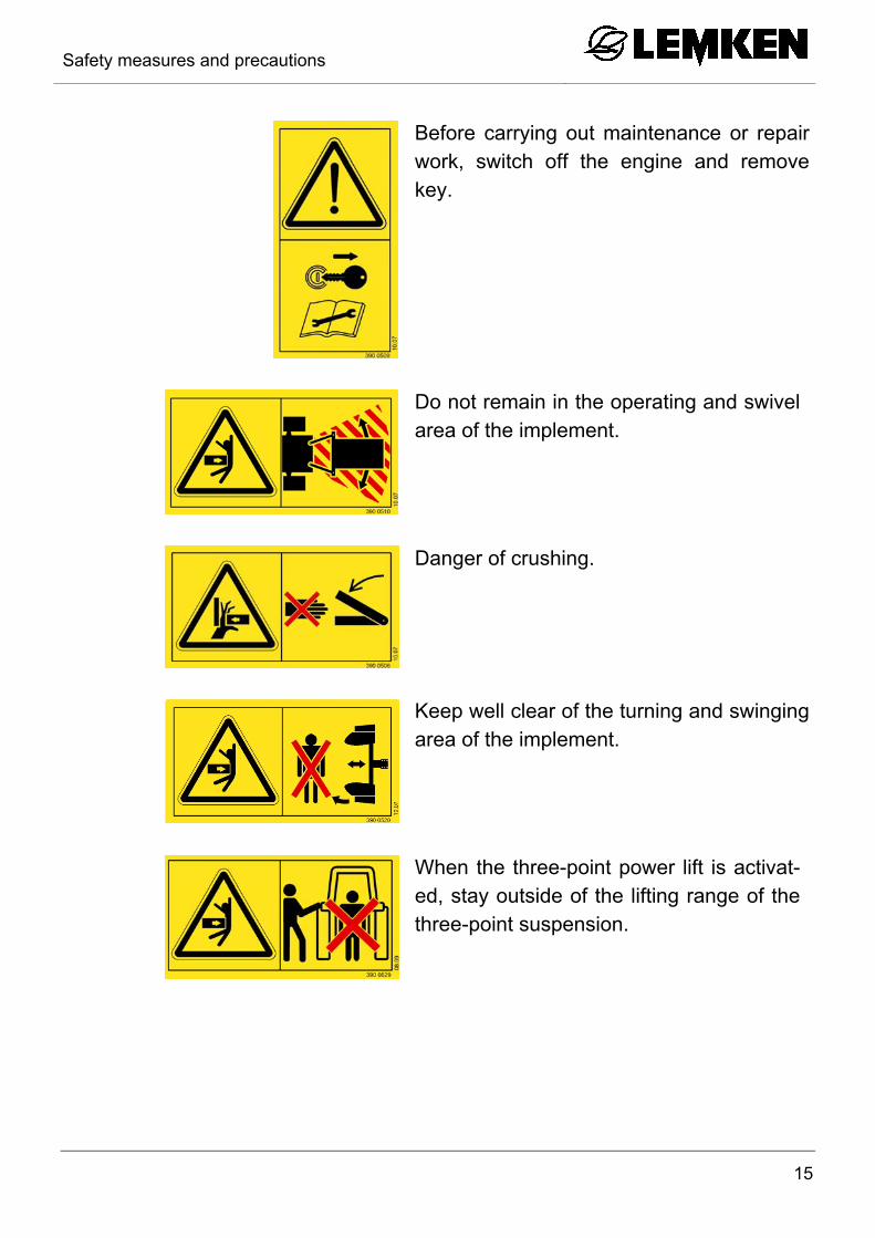
Before carrying out maintenance or repair work, switch off the engine and remove key.
Do not remain in the operating and swivel area of the implement.
Danger of crushing.
Keep well clear of the turning and swinging area of the implement.
When the three-point power lift is activat-ed, stay outside of the lifting range of the three-point suspension.

Safety measures and precautions
16
3.5 Special safety instructions
WARNING
Risk of injury due to non-observance of the currently valid occupational safety guidelines
If the currently valid occupational safety guidelines are bypassed or safety equipment is rendered unusable when handling the de-vice, there is a risk of injury.
The operator must personally monitor all work on and with the device.
The operator instructs his personnel in occupational safety ac-cording to the currently valid occupational safety guidelines.
WARNING
Risk of injury due to foreign objects ejected at high speed
During work there is a risk of injury to the face and body by lumps of earth, soil constituents or stones ejected at high speed.
During work there must be nobody directly in front of, behind or next to the device.
During work nobody must accompany the device.

Safety measures and precautions
17
WARNING
Risk of injury when freeing casualties
When rescuing people trapped or injured by the device, there is a risk of additional serious injury to the casualty if the hydraulic con-nections were not connected according to their colour coding as described in the section entitled "Required hydraulic equipment". As a result, functions may run in the opposite direction or may be inverted.
Before actuating the hydraulics, check that the hydraulic con-nections of the device are connected to the tractor according to the colour coding.
If there is no identification on the tractor and on the device or if the connections are not connected to the tractor according to their identification, it may not be possible to free the person safely.
If in doubt, leave casualties to be freed by specially trained rescue personnel.
WARNING
Risk of injury on parked implement
The implement is not a toy!
Climbing onto the parked implement can result in severe injuries, e.g. due to slipping or tripping.
Do not climb onto the parked implement.
3.6 Hazardous areas
WARNING
Moving hazardous area
The hazardous area of the device moves during operation of the device!
During operation of the device there must be nobody in front of the actual hazardous area, as the hazardous area moves with the device!

Safety measures and precautions
18
3.6.1 Hazardous areas during operation of the device
3.7 Residual risks
Residual risks are particular hazards which occur when handling the device and which cannot be eliminated despite a design in accordance with safety require-ments.
Residual risks are not usually obvious and may be the source of a potential injury or health hazard.
3.7.1 Hazard caused by mechanical systems
There is a risk of accidents due to crushing, cutting and striking body parts
on abruptly moving machine parts,
on moving machine parts caused by stored mechanical energy in elastic parts, such as springs,
on an inadequately stable device,
on the general shape or mounting location of components.

Safety measures and precautions
19
3.7.2 Hazard caused by hydraulic systems
There is a risk of injury to body parts, in particular the face, eyes and unprotected areas of skin, caused by burns and contamination with hydraulic fluid
due to hot/pressurised hydraulic fluid spraying out of leaking joints or lines,
due to bursting, pressurised lines or components.
3.8 Applicable rules and regulations
The applicable rules which must be observed during operation of the device are listed below:
Observe the currently valid national highway code!
Observe the currently valid national laws and regulations for occupational safe-ty.
Observe the currently valid national laws and regulations for operational safety.
3.9 Operation on public highways
3.9.1 Lighting system and identification
A proper lighting system, identification and equipment must be on the device if it is to be transported on public roads. Further information can be requested from the appropriate authorities.

Safety measures and precautions
20
3.9.2 Requirements of the tractor
Ensure that the tractor with mounted device always reaches the stipulated brak-ing deceleration.
Observe the permitted axle loads, gross weights and transportation dimensions, see also section entitled "Axle loads"!
Observe the permitted power limit of the tractor!
WARNING
Risk of accidents due to inadequate steerability
A tractor which is too small or which has inadequate front ballast cannot be manoeuvred safely or steered with adequate tracking stability. As a result, the driver or other road users may be injured or killed.
Only use a tractor which can be adequately ballasted and safely manoeuvred.
Ensure that the front axle of the tractor is always loaded with at least 20% of the net weight of the tractor. See section on "Axle loads".

Safety measures and precautions
21
3.9.3 Axle loads
Implements mounted to the front and rear three-point linkage must not result in the following being exceeded:
permissible gross weight of tractor,
permissible axle loads of tractor,
the tractor's tyre load-carrying capacities.
The tractor's front axle must always be loaded with at least 20 % of the tractor's curb weight.
The following data are required for the calculation:
from the tractor operating instructions,
from the implement operating instructions,
which are to be documented through remeasuring.

Safety measures and precautions
22
Data from tractor operating instructions
Take the following data from your tractor's operating instructions:
Abbreviation Data
TL Tractor kerb weight (kg) _______ kg
TV Front axle load (kg) of empty tractor _______ kg
TH Rear axle load (kg) of empty tractor _______ kg
Data from implement operating instructions
Take the following data from these operating instructions or from the documents for the front weight or rear weight:
Abbreviation Data
GH Gross weight (kg) for rear mounting implement or rear weight
_______ kg
GV Gross weight (kg) for front mounting implement or front weight
_______ kg
d Distance (m) between centre of lower control link ball and centre of gravity for rear mounting imple-ment or rear weight
_______ m

Safety measures and precautions
23
Data to be determined through remeasuring are
Determine the following data through remeasuring:
Abbreviation Data
a Distance (m) between centre of gravity for front mounting implement or front weight and centre of front axle
_______ m
b Tractor wheelbase (m) _______ m
c Distance (m) between centre of rear axle and centre of lower control link
_______ m

Safety measures and precautions
24
Calculation of minimum ballasting value at front GV min for rear mounting implement
Enter the calculated minimum ballasting value, as required at the front of the tractor, into the table.
Calculation of minimum ballasting value at rear GH min for front mounting im-plement
Enter the calculated minimum ballasting value, as required at the rear of the tractor, into the table.
Calculation of actual gross weight Gtat
Enter the value for the calculated actual gross weight and the permissible gross weight as given in the tractor's operating instructions into the table.
Calculation of actual front axle load TV tat
Enter the value for the calculated actual front axle load and the permissible front axle load as given in the tractor's operating instructions into the table.
GV x a – TH x b + (0.45 x TL x b)
b + c + d GH min =
GV x (a + b) + TV x b – GH x (c + d)
b TV tat =
Gtat = GV + TL + GH
GH x (c + d) – TV x b + (0.2 x TL x b)
a + b GV min =

Safety measures and precautions
25
Calculation of actual rear axle load TH tat
Enter the value for the calculated actual rear axle load and the permissible rear axle load as given in the tractor's operating instructions into the table.
Tyre load-carrying capacity
Enter double the value (for two tyres) for the permissible tyre load-carrying ca-pacity (see, e.g. tyre manufacturer's documentation) into the table.
Table Actual value ac-cording to calcula-
tion
Permissible value according to tractor
operating instructions
Double permissible tyre load-carrying
capacity [two tyres]
Minimum ballas-ting, front
GV min kg - -
Minimum ballas-ting, rear
GH min kg - -
Gross weight G tat kg < TL kg -
Front axle load TV tat kg < TV kg < kg
Rear axle load TH tat kg < TH kg < kg 3.9.4 Check before departure
Before driving with the implement raised, lock the control lever of the control unit; otherwise it may drop and the implement may be unintentionally lowered.
Mount and check the transport equipment such as the lighting system, warning signs and protective devices.
The actuating cables for the quick-release couplings of the tractor must hang loose and must not actuate themselves in any position.
Before starting up and operating the implement, check the immediate vicinity around it. No-one must be standing in this area!
Ensure that visibility is adequate.
Observe permitted axle loads, total weights and transportation dimensions.
TH tat = Gtat - TV tat

Safety measures and precautions
26
3.9.5 Correct behaviour in road traffic
When driving on public highways, observe the relevant statutory national regu-lations.
Driving behaviour, steering and braking performance are influenced by ballast weights.
Ensure that the tractor has adequate steering and braking performance.
When driving around corners, take into account the wide radius and the inertia of the device.
It is prohibited to transport people on the device. 3.10 Obligation of the operator
Before switching on the device, read the operating instructions.
Follow the safety instructions!
Wear appropriate protective clothing when carrying out any work on the device. Protective clothing must be tight-fitting!
Observe generally accepted and other obligatory regulations for the prevention of accidents and protection of the environment and add them to the operating instructions!
The operating instructions are an important component of the device.
Ensure that the operating instructions are always ready available at the installa-tion location of the device and are kept for the entire service life of the device.
If the device is sold or the operating company changes, pass on the operating instructions with the device!
Keep all safety instructions and danger warnings on the device in a completely legible state. The affixed safety and warning signs provide important information on safe operation. Comply with them to ensure your safety!
Do not alter, retrofit or modify the device, potentially impairing safety, without the approval of the manufacturer. The manufacturer is not liable for any damage resulting from arbitrary modifications to the device!
Operate the device only in compliance with all connection and default values provided by the manufacturer!
Use original spare parts only!

Safety measures and precautions
27
3.11 Operating the device safely
3.11.1 General information
Before starting work, familiarise yourself with all equipment and actuating ele-ments as well as their functions.
Do not operate the device until all protective devices have been attached and are in the safety position.
Always attach the device in accordance with the regulations and only on the stipulated devices.
Always exercise extreme caution when mounting the device on or removing it from the tractor.
In the area of the three-point linkage there is a risk of injury from crushing and/or shearing.
Before mounting the device on or removing it from the three-point linkage, move the operating equipment into the position which prevents the device from being uninitentionally raised or lowered.
When actuating the external control for the three-point attachment, do not walk between the tractor and device.
It is prohibited to be within the hazardous area of the machine and to climb up on the implement while it is operating.
In the wider operating range of the device there is a risk of injury, e.g. from ejected stones.
Before actuating hydraulic equipment (such as flap devices), ensure that there is nobody in the flap area. Risk crushing and/or shearing by remote power op-erated parts.
Never stand between tractor and device. This is only permitted when the tractor is secured against rolling away by the parking brake and the chocks.
Always keep the device in a clean state to prevent the risk of fire.
Before leaving the tractor, deposit the device on the ground.
Switch off the engine.
Remove the ignition key.

Safety measures and precautions
28
3.11.2 Personnel selection and qualifications
The driver of the tractor must have the appropriate driving licence.
Any work on the device may be carried out by trained and instructed personnel only. Personnel must not be on drugs, intoxicated or taking medication.
Servicing and maintenance work may be carried out by trained technicians or appropriately instructed persons only.
Only electricians may work on the electrical components in accordance with the electro-technical regulations.
3.11.3 Hydraulic system
The hydraulic system is under high pressure.
When connecting hydraulic cylinders and motors, ensure that the specified hy-draulic hose connection is used.
When connecting the hydraulic hoses to the tractor hydraulics, make sure that the hydraulic system is depressurised on both the tractor and the implement.
If there are hydraulic functional connections between the tractor and the imple-ment, coupling sleeves and plugs must be identified to prevent operating errors. If the connections are reversed, the function is reversed (e.g. raising/lowering) - Risk of accident.
Check hydraulic hose lines regularly and replace if damaged or showing signs of aging. The replacement hose lines must meet the technical requirements stipulated by the implement manufacturer.
When searching for leaks, use appropriate equipment because of the risk of in-jury.
Fluid (hydraulic fluid) which escapes under high pressure can penetrate the skin and cause severe injuries. If injuries occur, call a doctor immediately. Risk of in-fection.
Before working on the hydraulic system, set down the implement, depressurise the system and shut down the motor.

Handing over the Implement
29
4 HANDING OVER THE IMPLEMENT
As soon as the implement is delivered, ensure that it corresponds with the order package.
Also check the type and completeness of any supplied accessories.
When the device is handed over, your dealer will explain how it works.
As soon as the implement is handed over, familiarise yourself with the imple-ment and its functions.

Layout and description
30
5 LAYOUT AND DESCRIPTION 5.1 Overview
1 Headstock
2 Turnover device
3 Cross shaft
4 Optiquick adjustment centre
5 Basic frame
6 Depth wheel
7 Plough body
8 Additional tools (skimmer, trash-board)
9 Disc coulters - not shown
7
7
3
1
8
2
5 44

Layout and description
31
5.2 Description 5.2.1 Headstock
The headstock with top link pin and cross shaft conforms to ISO 730.
Cross shaft L2/Z2 conforms to category 2.
The top link pin conforms to category 1 + 2.
5.2.2 Turnover device
Ploughs in the Opal 090 series are fitted with the hydraulic D65 turnover device. 5.2.3 Optiquick adjustment system
The plough line and the front furrow width can be adjusted independently. This permits ploughing without lateral force at every working width.
5.2.4 Basic frame
Ploughs in the Opal 090 series have a 90 x 90 x 7 mm square profile frame.
The underframe clearance is 70 cm.
5.2.5 Depth wheel
The plough can be fitted with a 195 R15 depth control wheel, 650 x 198 mm

Layout and description
32
5.2.6 Plough bodies
Dural
The plough body consists of:
Mouldboard, made up of a shin (1) and a mouldboard (2), or slats (5).
Share, made up of a wing (3) and a point (4).
Frog (6)
Landside (7)
5.2.7 Additional tools
The following additional tools are available as accessories:
2
4
3
3
7
7
1
5
4
3

Layout and description
33
Trashboard (1)
Skimmer D1 (2) or M3 (3)
Sword coulter (4)
1
2
4
3

Layout and description
34
5.2.8 Disc coulters
The large, beaded (1) disk coulter provides for a clean furrow.
1
Preparations on tractor
35
6 PREPARATIONS ON TRACTOR
6.1 Tyres
The air pressure must be identical, particularly on the rear tractor tyres. Under dif-ficult conditions, additional wheel weights should be used or the tyres topped up evenly with water. See operating instructions of the tractor manufacturer.
6.2 Lifting rods
The lifting rods should be adjusted so they are as short as possible and of equal length. See operating instructions from the tractor manufacturer.
6.3 Top Link
Where there are alternative fitting positions at the tractor for the top link, fit the top link tractor-sided as hight as possible.
6.4 Chains and stabilisers of the three-way linkage
The chains or stabilisers must be adjusted so that they ensure adequate lateral movement of the lower link of the tractor during work.
They must be laterally locked if the lower links are raised and are in the transport position.
Some makes of tractor are equipped with automatic side struts, which must be specially adjusted. If the tractor suddenly pulls to one side or the implement works with different widths on the right and left, this may be caused by the side strut not having been released. The function of the locking device of the auto-matic side strut should be checked and re-adjusted if neces-sary. See the operating manual provided by the tractor manu-facturer.
6.5 Hydraulics
For work the tractor hydraulics must be set to ’Draft’ or ’Mixed’ Control. See manu-facturer’s instructions.

Preparations on tractor
36
6.6 Hydraulic equipment required
The implement is supplied as standard with separate hydraulic connections for each consumer. The protecting caps on the hydraulic connections are coloured and the hydraulic connections themselves are marked alphanumerically.
In order to activate the hydraulic devices, the tractor must be equipped with the following spool valves:
Consumer Single-acting Double-acting
Turnover ram (with return connection on tractor)
1
Turnover ram 1
Preparing the implement
37
7 PREPARING THE IMPLEMENT 7.1 General
Before using the implement for the first time, we recommend that you set it up as described below while you are still in the yard and familiarise yourself with the im-plement and its functions. The settings are adjusted with the implement mounted on the tractor.
7.2 Upper control link length
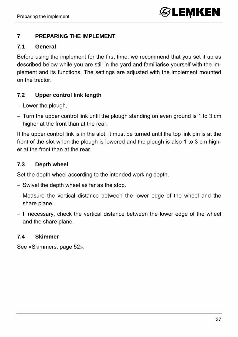
Lower the plough.
Turn the upper control link until the plough standing on even ground is 1 to 3 cm higher at the front than at the rear.
If the upper control link is in the slot, it must be turned until the top link pin is at the front of the slot when the plough is lowered and the plough is also 1 to 3 cm high-er at the front than at the rear.
7.3 Depth wheel
Set the depth wheel according to the intended working depth.
Swivel the depth wheel as far as the stop.
Measure the vertical distance between the lower edge of the wheel and the share plane.
If necessary, check the vertical distance between the lower edge of the wheel and the share plane.
7.4 Skimmer
See «Skimmers, page 52».

Preparing the implement
38
7.5 Setting the outer screw of the Optiquick adjustment centre
The outer screw (1) has been set to an ex-treme position to save space during trans-portation.
Adjust the outer screw (1) to the approx-imate length of the main link (2).
Carry out fine adjustments in the field.
7.1 Clearance required for turning
Lift the plough completely before turning it.
Check whether there is sufficient clear-ance between the plough and the ground for turning.
If there is insufficient clearance:
Turn the inner screw (3) to make it long-er.
Move the cross shaft (4) to a lower posi-tion or connect the top link in a higher position on the plough headstock.
1 2
4
4

Preparing the implement
39
7.2 Three-point connection
WARNING
Loss of the implement
The category of the three-point linkage on the tractor and the cat-egory of the cross shaft and top link pin must correspond, other-wise the cross shaft and top link pin may slip out of the connection when travelling on uneven ground or as a result of vibration.
Always ensure that the category of the three-point linkage and the diameter of the cross shaft and top link pin are exactly the same.
The maximum permissible tractor power and dimensions for each category in ac-cordance with ISO 730-1 are set out in the table below.
Tractor power Cat.
Diameter of drawbar
pivot (mm)
Length of drawbar
(shoulder distance)
(mm)
Distance, tractor lower
links (mm)
Distance between cross shaft and in-tersection point ex-
tension of lower links (mm)
kW hp A B C D 22 - 51 30 - 70 2 28 825 435 1800 - 2400

Attaching the implement
40
8 ATTACHING THE IMPLEMENT 8.1 Specific safety information
WARNING
Risk of injury from the parked implement
Never enter the danger zone between the tractor and imple-ment.
Read and observe the "Safety measures and precautions" sec-tion and the special safety instructions "Risk of injury from the parked implement".
The implement is not a play area.
Climbing on the parked implement may cause serious injuries, e.g. as a result of slipping or tripping.
Do not climb on the parked implement.
8.2 General
A plough which has been parked in the working position should be mounted on the tractor as follows:
Switch the tractor hydraulic system to position control.
Connect the lower links to the cross shaft (1).
Secure the lower links.
Pivot the stand (2) upwards.
Push spring clamps over the outer screw (3).
Secure the spring clamps.
1 2
3
5

Attaching the implement
41
Connect the top link so that it slopes upwards towards the plough during ploughing work.
Secure the top link pin (4).
Only use the top link pin supplied with the plough.
Switch the tractor hydraulic system to the float position.
Connect the hydraulic hoses.
During ploughing, switch the hydraulic system to draft control or mixed control. See the tractor manufacturer's operating instructions.
4

Uncoupling the implement
42
9 UNCOUPLING THE IMPLEMENT 9.1 Specific safety information
WARNING
Risk of injury from the parked implement
Never enter the danger zone between the tractor and imple-ment.
Read and observe the "Safety measures and precautions" sec-tion and the special safety instructions "Risk of injury from the parked implement".
The implement is not a play area.
Climbing on the parked implement may cause serious injuries, e.g. as a result of slipping or tripping.
Do not climb on the parked implement.
9.2 General
Unhitch the plough from the tractor as fol-lows:
The plough should be in the right-hand working position.
The plough must always be parked on firm, level ground.
Turn the plough frame into the working position.
Switch the tractor hydraulic system to position control.
Lower the plough completely.
Switch off the tractor engine.
Uncoupling the implement
43
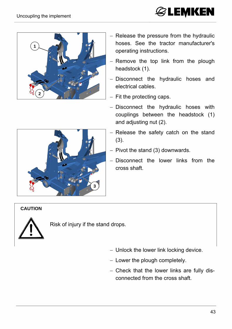
Release the pressure from the hydraulic hoses. See the tractor manufacturer's operating instructions.
Remove the top link from the plough headstock (1).
Disconnect the hydraulic hoses and electrical cables.
Fit the protecting caps.
Disconnect the hydraulic hoses with couplings between the headstock (1) and adjusting nut (2).
Release the safety catch on the stand (3).
Pivot the stand (3) downwards.
Disconnect the lower links from the cross shaft.
CAUTION
Risk of injury if the stand drops.
Unlock the lower link locking device.
Lower the plough completely.
Check that the lower links are fully dis-connected from the cross shaft.
1
2
3

Driving on public roads
44
10 DRIVING ON PUBLIC ROADS 10.1 Laws and regulations
All national laws and regulations relating to transport on public roads must be ob-served.

Operation
45
11 OPERATION 11.1 Specific safety information
CAUTION
Read and observe the "Safety measures and precautions" sec-tion.
This implement should always be used, operated and repaired by persons who are familiar with it and aware of the risks.
Before carrying out any adjustment or repair work or rectifying any malfunctions, always ensure that the driveline is switched off and the engine is stationary. Remove the ignition key.
DANGER
Risk of accidents during adjustment work
During all adjustment work there is a risk of crushing, cutting, trapping or knocking the hands, feet or body on heavy parts which may be under spring pressure and/or have sharp edges.
Adjustment work must always be carried out by trained personnel.
Always wear appropriate protective clothing.
Always follow the safety and accident prevention rules.
11.2 Turning the plough frame
DANGER
Observe the safety and precautionary measures, see page 12.
Before turning the plough, always ensure that nobody is stand-ing within the folding and swivelling range of the plough.
Only operate the turnover device from the tractor cab.
Ensure that the hydraulic hoses do not kink.
Always keep the hose connections clean.
Operation
46
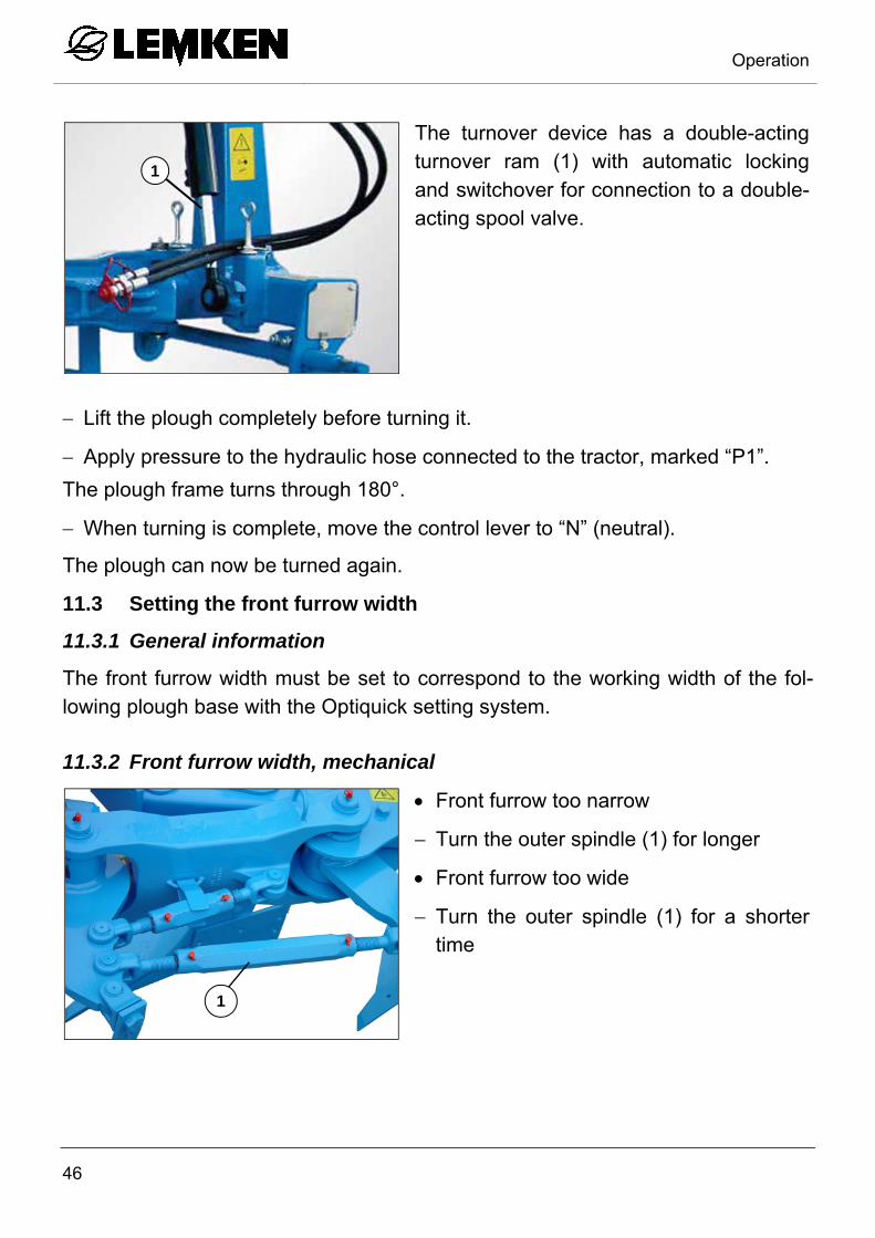
The turnover device has a double-acting turnover ram (1) with automatic locking and switchover for connection to a double-acting spool valve.
Lift the plough completely before turning it.
Apply pressure to the hydraulic hose connected to the tractor, marked “P1”.
The plough frame turns through 180°.
When turning is complete, move the control lever to “N” (neutral).
The plough can now be turned again.
11.3 Setting the front furrow width
11.3.1 General information
The front furrow width must be set to correspond to the working width of the fol-lowing plough base with the Optiquick setting system.
11.3.2 Front furrow width, mechanical
Front furrow too narrow
Turn the outer spindle (1) for longer
Front furrow too wide
Turn the outer spindle (1) for a shorter time
1
1

Operation
47
11.4 Setting the tractor/plough pull line
Set the tractor/plough pull line using the inner screw (2) so that there is no side pull.
Tractor pulls towards the ploughed land:
Turn the screw (2) to make it shorter.
Tractor pulls towards the unploughed land:
Turn the screw (2) to make it longer.
Never shorten the inner screw too much; this saves turning en-ergy, reduces oil heating, increases the lift height, reduces landside wear and reduces the traction requirement.
The inner screw is too long if the tractor pulls towards the ploughed land, the lower links are too tight and cannot move freely, or the lower links or headstock collide with parts of the tractor.
11.5 Angle
11.5.1 General information
When ploughing, the base blade should be almost vertical to the ground as seen from the direction of travel. The correct angle is set when the ploughing pattern is uniform.
If this is not the case, then the angular adjustment must be altered as described below.
2
Operation
48
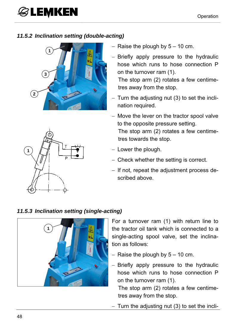
11.5.2 Inclination setting (double-acting)
Raise the plough by 5 – 10 cm.
Briefly apply pressure to the hydraulic hose which runs to hose connection P on the turnover ram (1). The stop arm (2) rotates a few centime-tres away from the stop.
Turn the adjusting nut (3) to set the incli-nation required.
Move the lever on the tractor spool valve to the opposite pressure setting. The stop arm (2) rotates a few centime-tres towards the stop.
Lower the plough.
Check whether the setting is correct.
If not, repeat the adjustment process de-scribed above.
11.5.3 Inclination setting (single-acting)
For a turnover ram (1) with return line to the tractor oil tank which is connected to a single-acting spool valve, set the inclina-tion as follows:
Raise the plough by 5 – 10 cm.
Briefly apply pressure to the hydraulic hose which runs to hose connection P on the turnover ram (1). The stop arm (2) rotates a few centime-tres away from the stop.
Turn the adjusting nut (3) to set the incli-
1
1
3
2
1

Operation
49
nation required.
Raise the plough completely.
Turn the plough completely.
Turn the plough back after 3–6 seconds.
Lower the plough.
Check whether the setting is correct.
If not, repeat the adjustment process de-scribed above.
11.6 Working depth
The working depth is set using the tractor hydraulics and, if fitted, the plough‘s depth wheel. For instructions on setting the tractor hydraulics, please refer to the operating instructions provided by the tractor manufacturer. The tractor hydraulics should be set to draft control or mixed control.
The depth wheel on the plough should only act as a depth control wheel and should prevent the plough from working too deep. Therefore the weight of the plough should be transferred to the tractor as far as possible to avoid excess wheel slip. Excess wheel slip causes premature tyre wear and increases fuel con-sumption.
11.7 DURAL plough body
11.7.1 Contact angle
The clearance between the share tips and the plough frame should be the same for all plough bodies. The dimension D should be approx. 1.5 cm. The necessary adjust-ment is made with the adjusting screw (1).
Loosen the body screw (2) and the clamping screw (3).
A
1
2
D
1

Operation
50
The bodies are mounted with the contact angle central to the ground. The contact angle can be changed with the adjusting screw (1) if required.
Adjust the adjusting screw (1).
Larger contact angle, notch (4) => better heeling.
Smaller contact angle, (5) => better depth guidance.
Then re-tighten all the screws.
See «Tightening torques, page 65».
11.7.2 Working width per body
The working width per body can be adjust-ed using wedges (1) which are bolted in place between the leg (2) and the frog (3). Three working widths per body are possib-le.
Narrow side of the wedge (1) pointing forwards => reduced working width per body
Without wedges => medium working width per body
Wide side of the wedge (1) pointing for-wards => increased working width per body
1
3
4
5
13
2
Operation
51
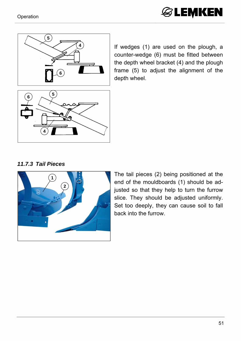
If wedges (1) are used on the plough, a counter-wedge (6) must be fitted between the depth wheel bracket (4) and the plough frame (5) to adjust the alignment of the depth wheel.
11.7.3 Tail Pieces
The tail pieces (2) being positioned at the end of the mouldboards (1) should be ad-justed so that they help to turn the furrow slice. They should be adjusted uniformly. Set too deeply, they can cause soil to fall back into the furrow.
4
5
6
6 5
4
1
2

Operation
52
11.8 Skimmers
11.8.1 General
The skimmers (1) should penetrate ap-proximately 5 - 10 cm deep into the soil and, when viewed from above, should ex-tend approximately 2 - 3 cm beyond the side of the share line.
11.8.2 Working depth
Loosen the bolts (2).
Set the skimmers (1) to the depth re-quired.
Tighten the bolts (2), see «Tightening torques, page 65».
11.8.3 Adjusting the projection angle
Loosen the bolts (2).
Move the skimmers (1) to the angle re-quired.
Tighten the bolts (2), see «Tightening torques, page 65».
Check the lateral position, see «Lateral position, page 53».
»»
1
1 2
1 2
Operation
53
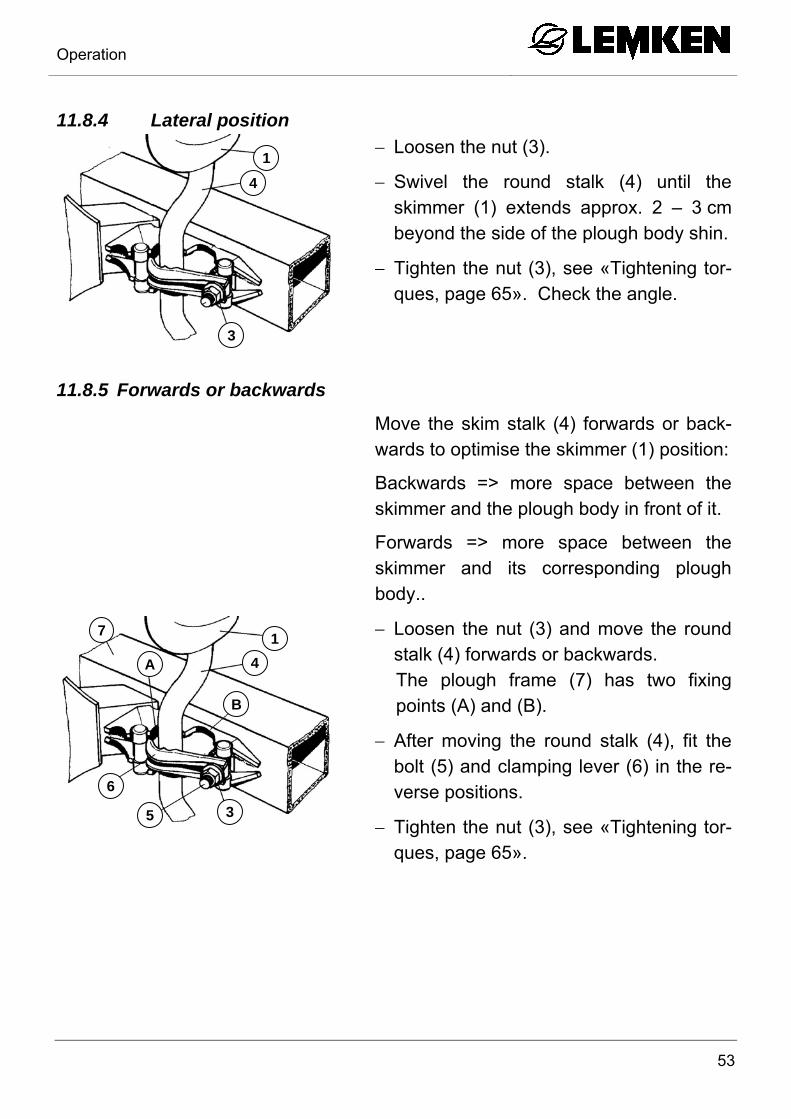
11.8.4 Lateral position
Loosen the nut (3).
Swivel the round stalk (4) until the skimmer (1) extends approx. 2 – 3 cm beyond the side of the plough body shin.
Tighten the nut (3), see «Tightening tor-ques, page 65». Check the angle.
11.8.5 Forwards or backwards
Move the skim stalk (4) forwards or back-wards to optimise the skimmer (1) position:
Backwards => more space between the skimmer and the plough body in front of it.
Forwards => more space between the skimmer and its corresponding plough body..
Loosen the nut (3) and move the round stalk (4) forwards or backwards. The plough frame (7) has two fixing points (A) and (B).
After moving the round stalk (4), fit the bolt (5) and clamping lever (6) in the re-verse positions.
Tighten the nut (3), see «Tightening tor-ques, page 65».
3
1
4
3
1
5
6
4
7
A
B
Operation
54
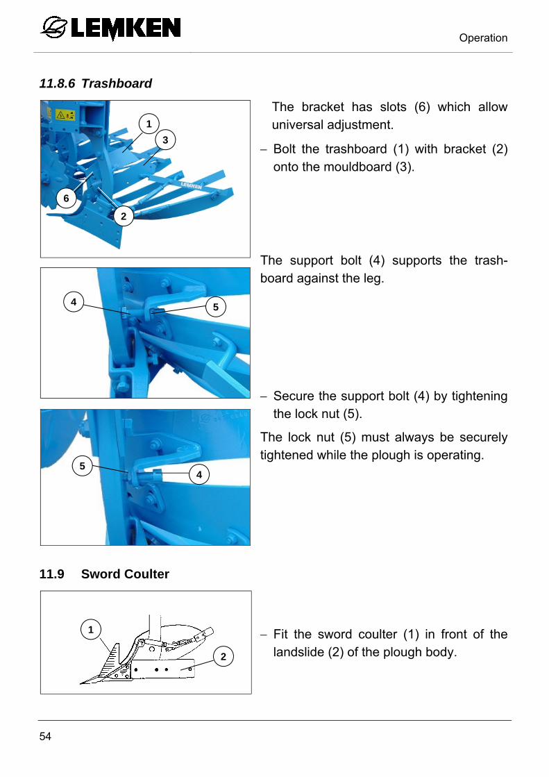
11.8.6 Trashboard
The bracket has slots (6) which allow universal adjustment.
Bolt the trashboard (1) with bracket (2) onto the mouldboard (3).
The support bolt (4) supports the trash-board against the leg.
Secure the support bolt (4) by tightening the lock nut (5).
The lock nut (5) must always be securely tightened while the plough is operating.
11.9 Sword Coulter
Fit the sword coulter (1) in front of the landslide (2) of the plough body.
2
3
6
1
4 5
4 5
2
1

Operation
55
11.10 Disc coulters
11.10.1 General
The disc coulters should operate at a depth of approximately 7 - 9 cm and should run approximately 2 - 3 cm to the side of the vertical shin.
11.10.2 Working depth
To adjust the working depth of the disc coulter:
Loosen the bolt (1).
Move the coulter arm (2) as required.
Before tightening the bolt (1) ensure that the teeth on the coulter arm (2) and adja-cent swivel bearing (3) are meshing to-gether correctly.
2
3
3
Operation
56
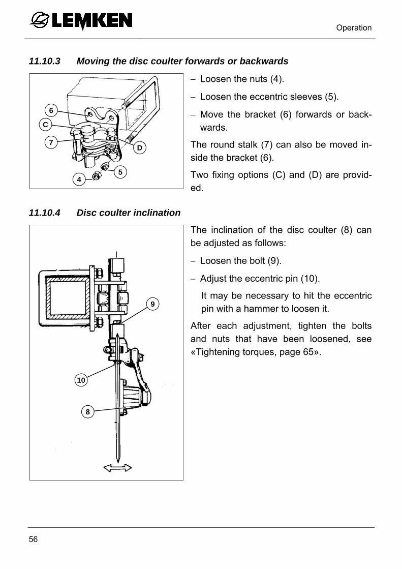
11.10.3 Moving the disc coulter forwards or backwards
Loosen the nuts (4).
Loosen the eccentric sleeves (5).
Move the bracket (6) forwards or back-wards.
The round stalk (7) can also be moved in-side the bracket (6).
Two fixing options (C) and (D) are provid-ed.
11.10.4 Disc coulter inclination
The inclination of the disc coulter (8) can be adjusted as follows:
Loosen the bolt (9).
Adjust the eccentric pin (10).
It may be necessary to hit the eccentric pin with a hammer to loosen it.
After each adjustment, tighten the bolts and nuts that have been loosened, see «Tightening torques, page 65».
D
C
7
6
54
10
9
8

Operation
57
Never reverse the tractor and implement while the disc coulters are still in the soil.
11.11 Depth control wheel
11.11.1 General
The plough can be supplied with a depth control wheel (1).
The depth control wheel (1) only has a depth control function. Set the tractor hy-draulics and top link length accordingly. See the tractor manufacturer's operating instructions.
11.11.2 Mounting
The depth control wheel and its bracket (2) are bolted onto the plough frame.
1
2

Operation
58
11.12 Working depth adjustment
Adjust the working depth using the screw (3).
Turn the screw (3) to make it shorter
=> increases working depth
Turn the screw (3) to make it longer
=> reduces working depth
If the adjustment range of the screw is in-adequate, the working depth can also be set using the bolts (4).
Turn the bolts (4) to make them shorter
=> increases working depth
Turn the bolts (4) to make them longer
=> reduces working depth
Ensure that both bolts (4) are set to the same length.
4
2
3

Operation
59
11.13 Shearing protection
DANGER
There are pinch and shear points in the area around the shearing protection.
Never stand in the plough body trip zone while ploughing is tak-ing place.
The plough bodies trip upwards when the shear bolt is overload-ed.
Keep a safe distance away.
Only shear bolts of the size and quality shown below should be used as these are the only bolts which provide effective protection against damage.
When a shear bolt (1) has broken, proceed as follows:
Loosen the bolt (2).
Remove the remains of the shear bolt.
Raise the implement and pivot the tripped plough body back into its working position.
Fit a new shear bolt (1).
Carefully tighten the shear bolt (1) and the bolt (2). See «Tightening torques, page 65».
Plough types Shear bolt
Size
Opal 090 M 14X60 - 8.8
M 14X75 - 8.8
1
2

Put the implement out of operation
60
12 PUT THE IMPLEMENT OUT OF OPERATION
12.1 Shutting down the implement in an emergency
In an emergency shut down the implement via the tractor.
Switch the tractor engine off.
Remove the ignition key.
CAUTION
Damage caused by improper storage of the implement
If incorrectly or improperly stored, the implement may be dam-aged, e.g. by humidity and dirt.
The implement should be deposited on a flat and adequately sta-ble base only.
Clean the implement prior to storage.
Lubricate the implement according to "Lubrication diagram".
12.2 Disposal
Metal and plastic components must be recycled.
When disposing of the implement, ensure that the individual compo-nents as well as the auxiliary and operating materials are disposed of in an environmentally friendly manner.

Maintenance and repairs
61
13 MAINTENANCE AND REPAIRS
13.1 Special safety instructions
13.1.1 General
WARNING
Risk of injury when carrying out maintenance and repair work
There is always the risk of injury when carrying out maintenance and repair work.
Use suitable tools, suitable climbing aids, platforms and support elements.
Always wear protective clothing.
Carry out maintenance and repair work only on an extended and deposited device or on a device secured by suitable sup-port elements to prevent it from extending or dropping.
13.1.2 Working under the raised device
WARNING
Risk of accident due to lowering and extending of compo-nents and devices
It is extremely dangerous to work under raised or next to retracted components and devices.
Always secure the tractor to prevent it from rolling away. Re-move the ignition key and secure the tractor to prevent it from being started up by unauthorised persons.
Support and secure raised or retracted components and devic-es with suitable support elements.

Maintenance and repairs
62
13.1.3 Immobilise the implement for maintenance and repairs
WARNING
Risk of accidents when tractor starts up
Injuries may occur if the tractor starts moving during maintenance and repair work.
Switch off the tractor engine before carrying out any work on the implement.
Secure the tractor against unintentional starting.
Remove the ignition key.
Affix a warning sign in front of the implement and in front of the tractor to advise outsiders of maintenance work.
Secure the tractor against rolling away using wheel chocks.
13.1.4 Working on the hydraulics
WARNING
Risk of accident from spurting hydraulic fluid
Fluid (hydraulic fluid) which escapes under high pressure may penetrate your skin and cause severe injuries. If injuries occur, call a doctor immediately. Always depressurise the hydraulic system before working on it.
Always wear appropriate protective clothing before working on the hydraulic system.
13.1.5 Personnel qualifications
CAUTION
Risk of accident due to inadequate qualifications of the maintenance and repair personnel
Maintenance and repair work require appropriate training.
All maintenance and repair work may only be carried out by trained and instructed personnel.

Maintenance and repairs
63
13.1.6 Protective equipment
CAUTION
Risk of accident due to working without protective equipment
There is always an increased risk of accidents when carrying out maintenance work and repairs.
Always wear appropriate protective equipment.
13.1.7 Utilised tool
WARNING
Risk of accident due to use of unsuitable tool
If working with an unsuitable or defective tool, there is a risk of ac-cidents and injuries.
Perform all work on the device with a suitable and functional tool only. This applies in particular to the use of lifting gear.
WARNING
Risk of back injuries
If your posture is not correct when installing or fixing heavy or cumbersome components, you may suffer back injuries which re-quire long convalescence.
Installation and maintenance work may be carried out by trained and instructed personnel only.
Perform all work on the device with a suitable and functional tool only. This applies in particular to the use of lifting gear.
WARNING
Risk of accident due to tool slipping off
If applying a large force, e.g. when loosening bolts, the tool may slip off. This may result in hand injuries on sharp-edged parts.
Avoid applying a large force by using suitable auxiliary equip-ment (e.g. extensions).
Check nuts and bolt heads, etc. for wear and, if required, consult an expert.
Maintenance and repairs
64
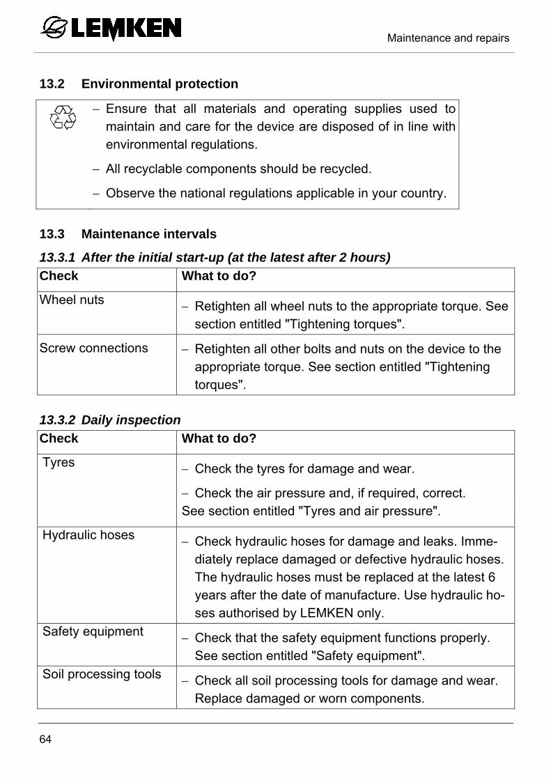
13.2 Environmental protection
Ensure that all materials and operating supplies used to maintain and care for the device are disposed of in line with environmental regulations.
All recyclable components should be recycled.
Observe the national regulations applicable in your country.
13.3 Maintenance intervals
13.3.1 After the initial start-up (at the latest after 2 hours)
Check What to do?
Wheel nuts Retighten all wheel nuts to the appropriate torque. See section entitled "Tightening torques".
Screw connections Retighten all other bolts and nuts on the device to the appropriate torque. See section entitled "Tightening torques".
13.3.2 Daily inspection
Check What to do?
Tyres Check the tyres for damage and wear.
Check the air pressure and, if required, correct. See section entitled "Tyres and air pressure".
Hydraulic hoses Check hydraulic hoses for damage and leaks. Imme-diately replace damaged or defective hydraulic hoses. The hydraulic hoses must be replaced at the latest 6 years after the date of manufacture. Use hydraulic ho-ses authorised by LEMKEN only.
Safety equipment Check that the safety equipment functions properly. See section entitled "Safety equipment".
Soil processing tools Check all soil processing tools for damage and wear. Replace damaged or worn components.

Maintenance and repairs
65
13.3.3 Weekly inspection
Check What to do?
Wheel nuts Check that all wheel nuts are tight and, if re-quired, retighten the wheel nuts to the appro-priate torque.
Screw connections Retighten all other bolts and nuts on the device to the appropriate torque.
If required, secure the screw connections with locking compound.
See section entitled "Tightening torques".
13.4 Tightening torques
13.4.1 General information
Once loosened, secure self-locking nuts against self-loosening by
exchanging the nuts with new self-locking nuts.
using safety washers.
using thread-locking compounds, such as Loctite.
The following tightening torques refer to screw threaded fittings not specifically mentioned in these operating instructions. Special tightening torques are indicated in the text.
Maintenance and repairs
66
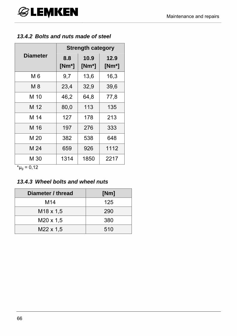
13.4.2 Bolts and nuts made of steel
Diameter
Strength category
8.8 [Nm*]
10.9 [Nm*]
12.9 [Nm*]
M 6 9,7 13,6 16,3
M 8 23,4 32,9 39,6
M 10 46,2 64,8 77,8
M 12 80,0 113 135
M 14 127 178 213
M 16 197 276 333
M 20 382 538 648
M 24 659 926 1112
M 30 1314 1850 2217
*μg = 0,12
13.4.3 Wheel bolts and wheel nuts
Diameter / thread [Nm]
M14 125
M18 x 1,5 290
M20 x 1,5 380
M22 x 1,5 510

Maintenance and repairs
67
13.5 Tyre pressure DANGER
Too high a tyre pressure can cause the tyres to burst and too low a tyre pressure can result in overloading of the tyres.
The tyre pressure shown below is permitted, depending on tyre size, tread and PR number or load index. The PR number or load index and tread designation are vulcanised into the tyres.
Tyre size Tread Ply ra-
ting [PR]Maximum permissible
tyre pressure [bar]
195 R 15 --- 4 2.3
13.6 Check the connections to the tractor
13.6.1 Hydraulic connections
WARNING
Risk of accidents due to escaping hydraulic fluid
Hydraulic fluid which is ejected under high pressure (hydraulic oil) can penetrate the skin and cause serious injuries. In the event of injuries, consult a doctor immediately.
Due to the risk of injury, always use suitable tools when looking for leaks.
Always wear appropriate protective clothing.
Carry out a visual inspection of the hydraulic couplings.
Look for leaking hydraulic oil at the hydraulic couplings.
Connect the hydraulic lines to the tractor.
Check that the hoses are leak-free when under pressure.
Faulty or leaking couplings must be repaired or replaced immediately by a special-ist workshop.

Maintenance and repairs
68
13.6.2 Electrical connections
Carry out a visual inspection of the plugs and cables.
Look for bent or broken contact pins on the plugs and exposed areas on the cables.
Apply anti-corrosion spray to the electrical contacts.
Faulty plugs or cables must be repaired or replaced immediately by a specialist workshop.

Maintenance and repairs
69
13.6.3 Lubrication chart
Every Before and after
10 50 100 a long
operating hours winter break
Turnover device bearing and ram pivots
x x
Optiquick
adjustment centre x x
Turnbuckles
x
Swivelling axes on depth wheel
x x
Depth wheel bearing
x x
Disc coulter bearing
x x
Screw thread of the inclination adjust-ment device
x

Troubleshooting
70
14 TROUBLESHOOTING 14.1 Hydraulic equipment
Fault Cause Solution
Plough rattles during the first stage of turning.
Plough frame is moving ahead, a vacuum is cre-ated in the turnover ram.
Fit a smaller throttle in the turnover ram connection (T).
V
P
T

Troubleshooting
71
Fault Cause Solution
Plough frame turns as far as the middle position and stays there.
The tractor hydraulics are not reaching the switch-over pressure needed for the turnover ram.
The preset switch-over pressure can be reduced by re-moving the washers (U). Removing one washer equates to a switchover pres-sure reduction of approx. 10 bar. The washers (U) are lo-cated behind the plug (V).
Check the trac-tor's hydraulic system.
Maintain the hy-draulic system if necessary.
V
P
T

Troubleshooting
72
Fault Cause Solution
The plough frame turns but the turnover ram switches over be-fore reaching the half-turned position and the plough frame turns back again.
The pre-set switchover pressure is too low.
Increase the pre-set switchover pressure by fit-ting additional washers (U).
The bearings of the turn-over device are dam-aged.
Check the bea-rings.
Replace the bearings if nec-essary.
The turnover ram switches over immediately without turning the plough frame.
The pre-set switchover pressure is too low.
Increase the pre-set switchover pressure by fit-ting additional washers (U).
The cone or cone seat in the switchover valve is faulty or leaking.
Replace the tur-nover ram.
Troubleshooting
73
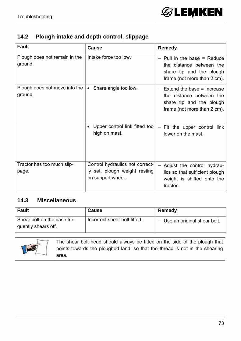
14.2 Plough intake and depth control, slippage
Fault Cause Remedy
Plough does not remain in the ground.
Intake force too low. Pull in the base = Reduce the distance between the share tip and the plough frame (not more than 2 cm).
Plough does not move into the ground.
Share angle too low. Extend the base = Increase the distance between the share tip and the plough frame (not more than 2 cm).
Upper control link fitted too high on mast.
Fit the upper control link lower on the mast.
Tractor has too much slip-page.
Control hydraulics not correct-ly set, plough weight resting on support wheel.
Adjust the control hydrau-lics so that sufficient plough weight is shifted onto the tractor.
14.3 Miscellaneous
Fault Cause Remedy
Shear bolt on the base fre-quently shears off.
Incorrect shear bolt fitted. Use an original shear bolt.
The shear bolt head should always be fitted on the side of the plough that points towards the ploughed land, so that the thread is not in the shearing area.

Technical data
74
15 TECHNICAL DATA 15.1 Permissible power range and weight
Description Number of
furrows Weight
Tractor power
kg (approx.) hp kW
Opal 090 2 340 30-45 22-33
Opal 090 2 + 1 465 45-60 33-44
Opal 090 3 460 55-70 40-51

Identification plate
75
16 IDENTIFICATION PLATE
The identification plate (1) is situated on the front of the three-point tower.
1

Index
76
INDEX
Additional tools ..................................................................................................... 32
Adjusting the projection angle .............................................................................. 52
Angular adjustment ............................................................................................... 47
Axle loads ............................................................................................................. 21
Contact angle ....................................................................................................... 49
Depth control wheel .............................................................................................. 57
Depth wheel .......................................................................................................... 37
Disc coulters ......................................................................................................... 55
Dural ..................................................................................................................... 32
DURAL plough body ............................................................................................. 49
Front furrow width ................................................................................................. 46
Hydraulic equipment ............................................................................................. 36
Hydraulics ............................................................................................................. 35
IDENTIFICATION PLATE ..................................................................................... 75
MAINTENANCE ................................................................................................... 61
Plough body .......................................................................................................... 32
Power range ......................................................................................................... 74
Preparations on tractor ......................................................................................... 35
REPAIRS .............................................................................................................. 61
Shearing protection .............................................................................................. 59
Skimmer ............................................................................................................... 37
Skimmers .............................................................................................................. 52
Sword Coulter ....................................................................................................... 54
Tail Pieces ............................................................................................................ 51
TECHNICAL DATA ............................................................................................... 74
Three-point connection ......................................................................................... 39
Top Link ................................................................................................................ 35

Index
77
Trashboard ........................................................................................................... 54
Tyre pressure ....................................................................................................... 67
Tyres ..................................................................................................................... 67
UNCOUPLING ...................................................................................................... 42
Warning signs ....................................................................................................... 13
Working depth ...................................................................................................... 49
Working depth adjustment .................................................................................... 58


