
1/24/2006 1
Verilog HDL Introduction
ECE 554 Digital Engineering Laboratory
Charles R. Kime and Michael J. Schulte(Updated: Kewal K. Saluja)
1/24/2006 2
Overview
Simulation and Synthesis Modules and Primitives Styles Structural Descriptions Language Conventions Data Types Delay Behavioral Constructs Compiler Directives Simulation and Testbenches
1/24/2006 3
Simulation and Synthesis
Simulation tools typically accept full set of Verilog language constructs
Some language constructs and their use in a Verilog description make simulation efficient and are ignored by synthesis tools
Synthesis tools typically accept only a subset of the full Verilog language constructs• In this presentation, Verilog language constructs not
supported in Synopsys FPGA Express are in red italics• There are other restrictions not detailed here, see
[2].
1/24/2006 4
Modules
The Module Concept• Basic design unit• Modules are:
Declared Instantiated
• Modules declarations cannot be nested
1/24/2006 5
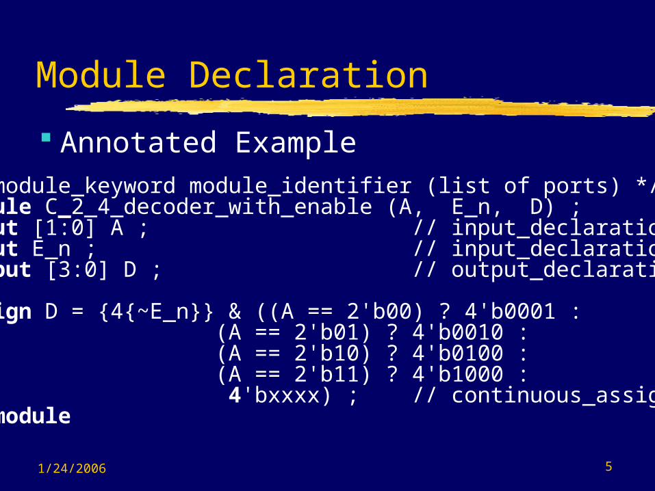
Module Declaration
Annotated Example/* module_keyword module_identifier (list of ports) */module C_2_4_decoder_with_enable (A, E_n, D) ; input [1:0] A ; // input_declarationinput E_n ; // input_declarationoutput [3:0] D ; // output_declaration
assign D = {4{~E_n}} & ((A == 2'b00) ? 4'b0001 : (A == 2'b01) ? 4'b0010 :
(A == 2'b10) ? 4'b0100 : (A == 2'b11) ? 4'b1000 :
4'bxxxx) ; // continuous_assignendmodule

1/24/2006 6
Module Declaration
Identifiers - must not be keywords! Ports
• First example of signals • Scalar: e. g., E_n• Vector: e. g., A[1:0], A[0:1], D[3:0], and D[0:3]
Range is MSB to LSB Can refer to partial ranges - D[2:1]
• Type: defined by keywords input output inout (bi-directional)
1/24/2006 7
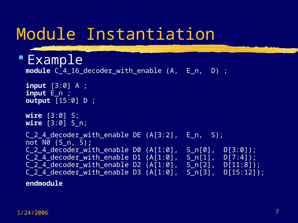
Module Instantiation
module C_4_16_decoder_with_enable (A, E_n, D) ;
input [3:0] A ; input E_n ; output [15:0] D ;
wire [3:0] S;wire [3:0] S_n;
C_2_4_decoder_with_enable DE (A[3:2], E_n, S);not N0 (S_n, S);C_2_4_decoder_with_enable D0 (A[1:0], S_n[0], D[3:0]);C_2_4_decoder_with_enable D1 (A[1:0], S_n[1], D[7:4]);C_2_4_decoder_with_enable D2 (A[1:0], S_n[2], D[11:8]);C_2_4_decoder_with_enable D3 (A[1:0], S_n[3], D[15:12]);
endmodule
Example

1/24/2006 8
Module Instantiation
• Single module instantiation for five module instances
C_2_4_decoder_with_enable DE (A[3:2], E_n, S),D0 (A[1:0], S_n[0], D[3:0]),D1 (A[1:0], S_n[1], D[7:4]),D2 (A[1:0], S_n[2], D[11:8]),D3 (A[1:0], S_n[3], D[15:12]);
• Named_port connection
C_2_4_decoder_with_enable DE (.E_n (E_n), .A (A[3:2]) .D (S));// Note order in list no longer important (E_n and A interchanged).
More Examples

1/24/2006 9
Primitives
Gate Level• and, nand• or, nor• xor, xnor• buf , not• bufif0, bufif1, notif0, notif1 (three-state)
Switch Level• *mos where * is n, p, c, rn, rp, rc; pullup,
pulldown; *tran+ where * is (null), r and + (null), if0, if1 with both * and + not (null)
1/24/2006 10
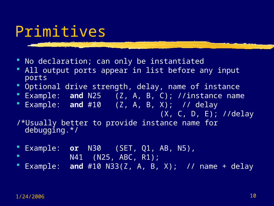
Primitives
No declaration; can only be instantiated All output ports appear in list before any input ports Optional drive strength, delay, name of instance Example: and N25 (Z, A, B, C); //instance name Example: and #10 (Z, A, B, X); // delay (X, C, D, E); //delay/*Usually better to provide instance name for
debugging.*/
Example: or N30 (SET, Q1, AB, N5), N41 (N25, ABC, R1); Example: and #10 N33(Z, A, B, X); // name + delay

1/24/2006 11
Styles
Structural - instantiation of primitives and modules
RTL/Dataflow - continuous assignments
Behavioral - procedural assignments

1/24/2006 12
Style Example - Structural
module half_add (X, Y, S, C);
input X, Y ;output S, C ;
xor (S, X, Y) ;and (C, X, Y) ;
endmodule
module full_add (A, B, CI, S, CO) ;
input A, B, CI ;output S, CO ;
wire N1, N2, N3;
half_add HA1 (A, B, N1, N2), HA2 (N1, CI, S, N3);
or P1 (CO, N3, N2);
endmodule

1/24/2006 13
Style Example - RTL/Dataflow
module fa_rtl (A, B, CI, S, CO) ;
input A, B, CI ;output S, CO ;
assign S = A ^ B ^ CI; //continuous assignment
assign CO = A & B | A & CI | B & CI; //continuous assignment
endmodule

1/24/2006 14
Style Example - Behavioral
module fa_bhv (A, B, CI, S, CO) ;
input A, B, CI ;output S, CO ;
reg S, CO; // required to “hold” values between events.
always@(A or B or CI) //; begin
S <= A ^ B ^ CI; // procedural assignment CO <= A & B | A & CI | B & CI;// procedural assignment end endmodule

1/24/2006 16
Connections
By position association• module C_2_4_decoder_with_enable (A, E_n, D);• C_4_16_decoder_with_enable DX (X[3:2], W_n,
word);• A = X[3:2], E_n = W_n, D = word
By name association• module C_2_4_decoder_with_enable (A, E_n, D);• C_2_4_decoder_with_enable DX (.E_n(W_n), .A(X[3:2]),
.D(word));• A = X[3:2], E_n = W_n, D = word
1/24/2006 17
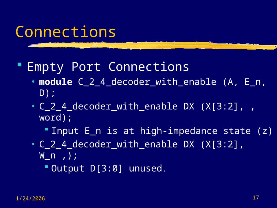
Connections
Empty Port Connections• module C_2_4_decoder_with_enable (A, E_n, D);• C_2_4_decoder_with_enable DX (X[3:2], , word);
Input E_n is at high-impedance state (z)• C_2_4_decoder_with_enable DX (X[3:2], W_n ,);
Output D[3:0] unused.

1/24/2006 18
Arrays of Instances
{ , } is concatenate Example
module add_array (A, B, CIN, S, COUT) ;
input [7:0] A, B ;input CIN ;output [7:0] S ;output COUT ;
wire [7:1] carry;
full_add FA[7:0] (A,B,{carry, CIN},S,{COUT, carry});// instantiates eight full_add modules
endmodule

1/24/2006 19
Language Conventions
Case-sensitivity• Verilog is case-sensitive.• Some simulators are case-insensitive• Advice: - Don’t use case-sensitive feature!• Keywords are lower case
Different names must be used for different items within the same scope
Identifier alphabet:• Upper and lower case alphabeticals• decimal digits• underscore

1/24/2006 20
Language Conventions
Maximum of 1024 characters in identifier First character not a digit Statement terminated by ; Free format within statement except for within
quotes• Strings enclosed in double quotes and must be on a single
line Comments:
• All characters after // in a line are treated as a comment• Multi-line comments begin with /* and end with */
Compiler directives begin with // synopsys Built-in system tasks or functions begin with $

1/24/2006 21
Logic Values
Verilog signal values• 0 - Logical 0 or FALSE• 1 - Logical 1 or TRUE• x, X - Unknown logic value• z, Z - High impedance condition
Also may have associated signal and charge strengths for switch level modeling of MOS devices
• 7 signal strengths plus 3 charge strengths
1/24/2006 22
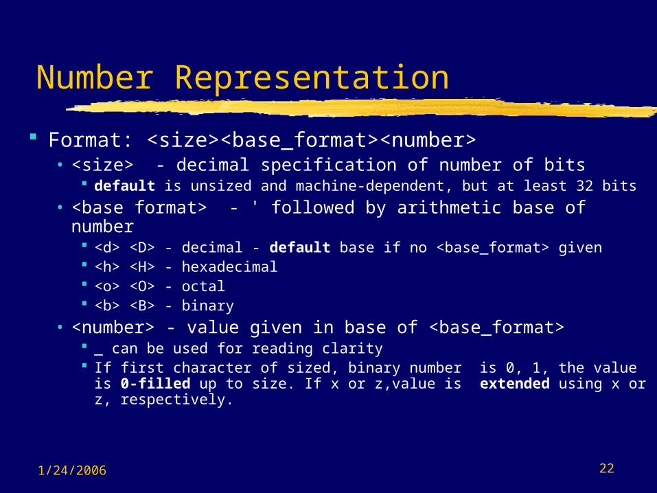
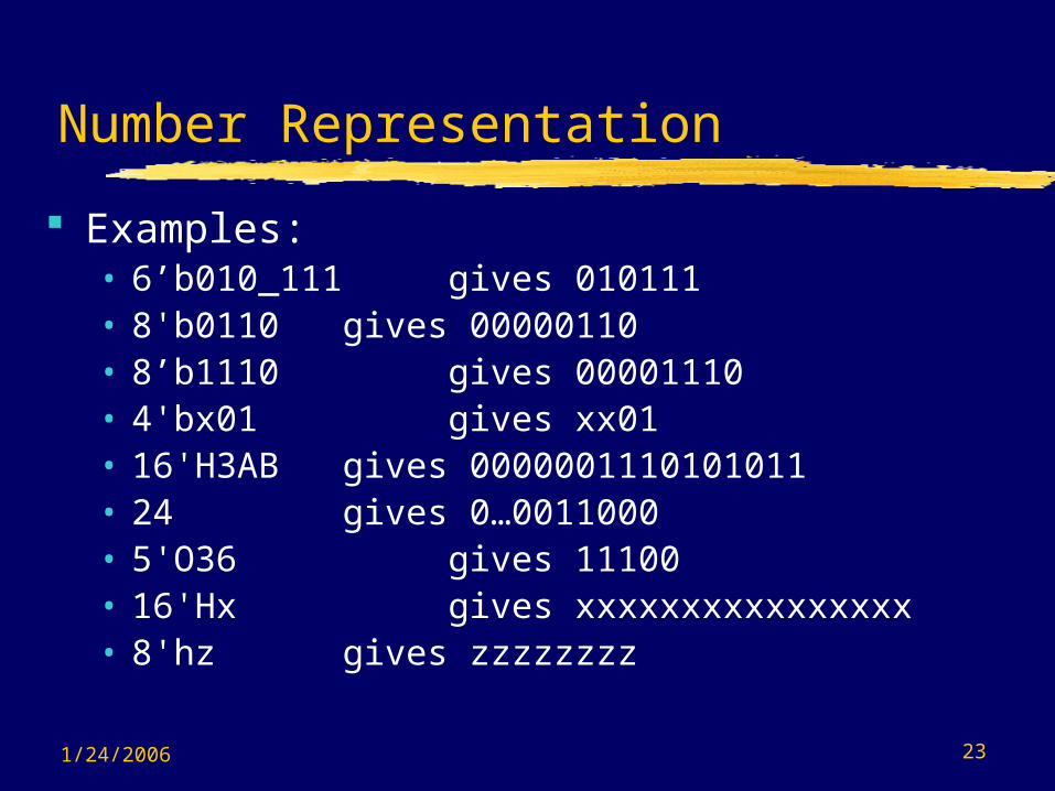
Number Representation
Format: <size><base_format><number>• <size> - decimal specification of number of bits
default is unsized and machine-dependent, but at least 32 bits
• <base format> - ' followed by arithmetic base of number <d> <D> - decimal - default base if no <base_format> given <h> <H> - hexadecimal <o> <O> - octal <b> <B> - binary
• <number> - value given in base of <base_format> _ can be used for reading clarity If first character of sized, binary number is 0, 1, the value is 0-
filled up to size. If x or z,value is extended using x or z, respectively.
1/24/2006 23
Number Representation
Examples:• 6’b010_111gives 010111• 8'b0110 gives 00000110• 8’b1110 gives 00001110• 4'bx01 gives xx01• 16'H3AB gives 0000001110101011• 24 gives 0…0011000• 5'O36 gives 11100• 16'Hx gives xxxxxxxxxxxxxxxx• 8'hz gives zzzzzzzz
1/24/2006 24
Variables
Nets• Used for structural connectivity
Registers• Abstraction of storage (May or may not be
real physical storage) Properties of Both
• Informally called signals• May be either scalar (one bit) or vector
(multiple bits)
1/24/2006 25
Data Types - Nets - Semantics wire - connectivity only; no logical tri - same as wire, but indicates will be
3-stated in hardware wand - multiple drivers - wired and wor - multiple drivers - wired or triand - same as wand, but 3-state trior - same as wor but 3-state supply0 - Global net GND supply1 - Global Net VCC (VDD) tri0, tri1, trireg

1/24/2006 26
Net Examples
wire x; wire x, y; wire [15:0] data, address; wire vectored [1:7] control; wire address = offset + index; wor interrupt_1, interrupt_2; tri [31:0] data_bus, operand_bus; Value implicitly assigned by connection to
primitive or module output
1/24/2006 27
Initial Value & Undeclared Nets
Initial value of a net• At tsim = 0, initial value is x.
Undeclared Nets - Default type• Not explicitly declared default to wire• default_nettype compiler directive can
specify others except for supply0 and supply1
1/24/2006 28
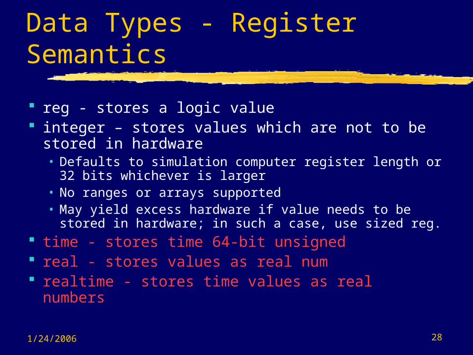
Data Types - Register Semantics
reg - stores a logic value integer – stores values which are not to be
stored in hardware• Defaults to simulation computer register length or
32 bits whichever is larger• No ranges or arrays supported• May yield excess hardware if value needs to be
stored in hardware; in such a case, use sized reg. time - stores time 64-bit unsigned real - stores values as real num realtime - stores time values as real numbers
1/24/2006 29
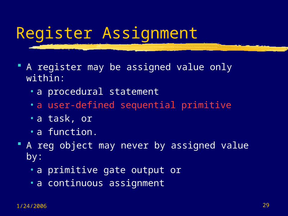
Register Assignment
A register may be assigned value only within:• a procedural statement• a user-defined sequential primitive• a task, or • a function.
A reg object may never by assigned value by:• a primitive gate output or • a continuous assignment
1/24/2006 30
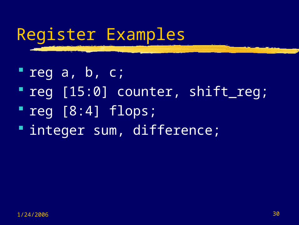
Register Examples
reg a, b, c; reg [15:0] counter, shift_reg; reg [8:4] flops; integer sum, difference;

1/24/2006 31
Strings
No explicit data type Must be stored in reg whose size is
8*(num. of characters) reg [255:0] buffer; //stores 32
characters

1/24/2006 32
Constants (Paramters)
Declaration of parameters• parameter A = 2’b00, B = 2’b01, C =
2’b10;• parameter regsize = 8;
reg [regsize - 1:0]; /* illustrates use of parameter regsize */
1/24/2006 33
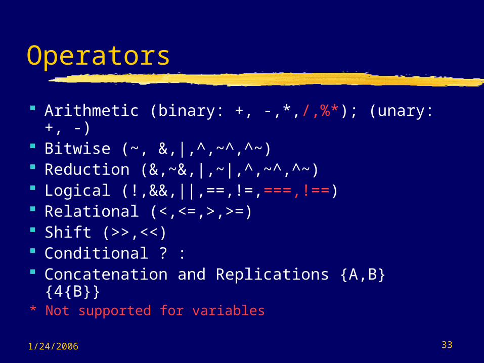
Operators
Arithmetic (binary: +, -,*,/,%*); (unary: +, -) Bitwise (~, &,|,^,~^,^~) Reduction (&,~&,|,~|,^,~^,^~) Logical (!,&&,||,==,!=,===,!==) Relational (<,<=,>,>=) Shift (>>,<<) Conditional ? : Concatenation and Replications {A,B}
{4{B}}* Not supported for variables

1/24/2006 34
Expression Bit Widths
Depends on:• widths of operands and• types of operators
Verilog fills in smaller-width operands by using zero extension.
Final or intermediate result width may increase expression width
1/24/2006 35
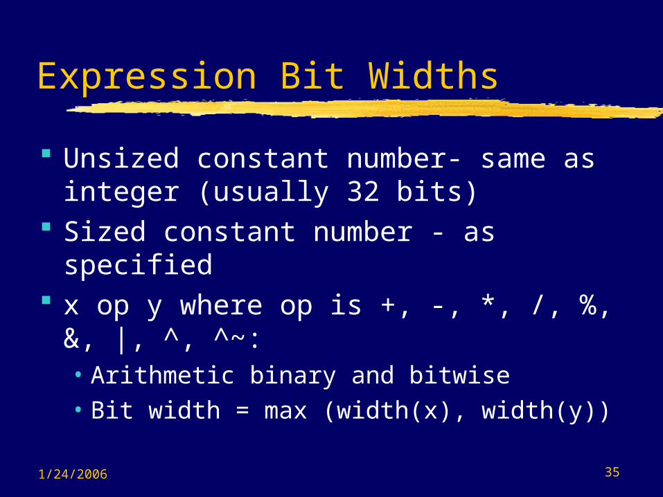
Expression Bit Widths
Unsized constant number- same as integer (usually 32 bits)
Sized constant number - as specified x op y where op is +, -, *, /, %, &, |,
^, ^~:• Arithmetic binary and bitwise• Bit width = max (width(x), width(y))
1/24/2006 36
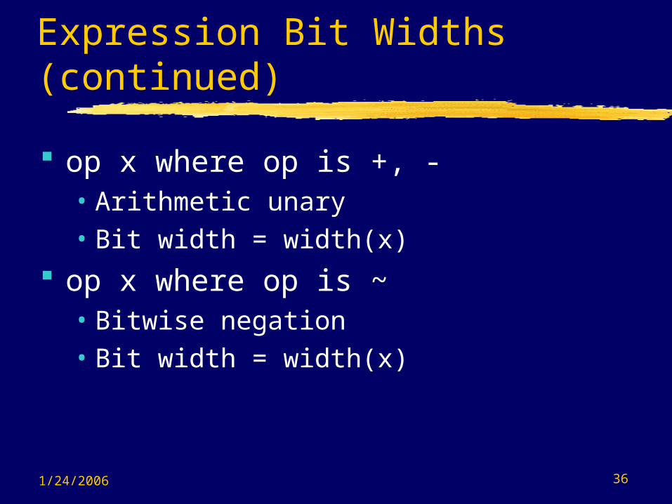
Expression Bit Widths (continued)
op x where op is +, - • Arithmetic unary• Bit width = width(x)
op x where op is ~• Bitwise negation• Bit width = width(x)
1/24/2006 37
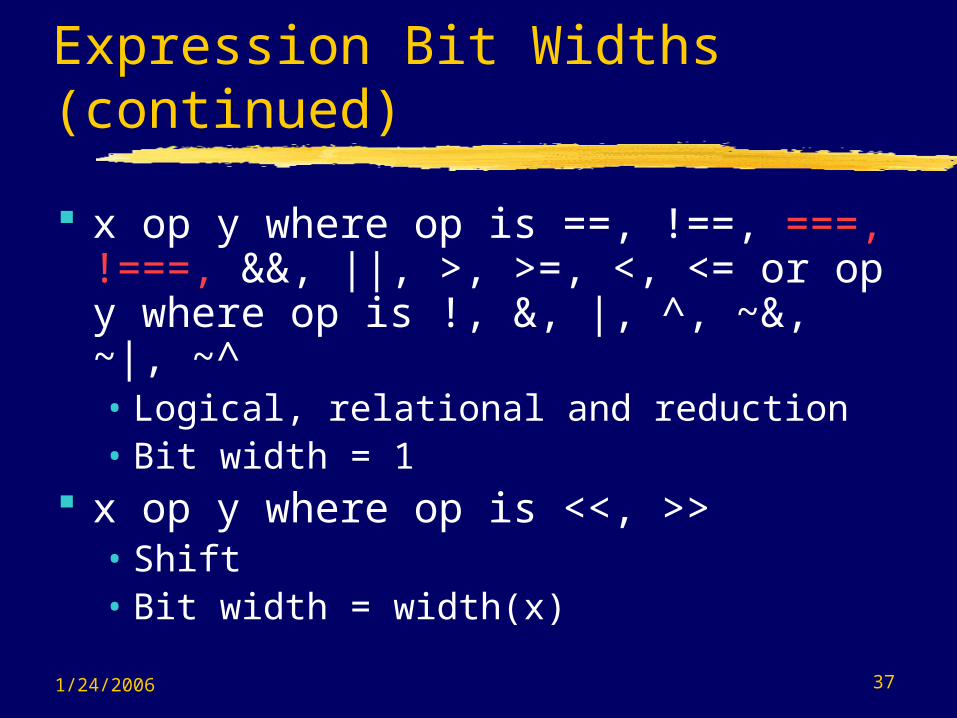
Expression Bit Widths (continued)
x op y where op is ==, !==, ===, !===, &&, ||, >, >=, <, <= or op y where op is !, &, |, ^, ~&, ~|, ~^ • Logical, relational and reduction• Bit width = 1
x op y where op is <<, >>• Shift• Bit width = width(x)
1/24/2006 38
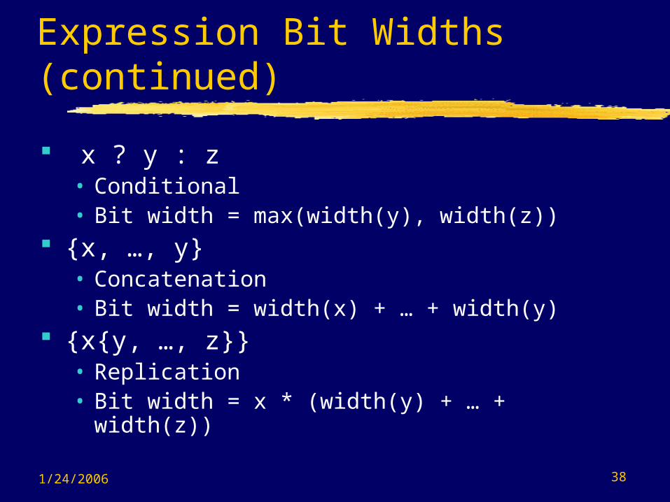
Expression Bit Widths (continued)
x ? y : z • Conditional• Bit width = max(width(y), width(z))
{x, …, y}• Concatenation• Bit width = width(x) + … + width(y)
{x{y, …, z}} • Replication• Bit width = x * (width(y) + … + width(z))

1/24/2006 39
Expressions with Operands Containing x or z
Arithmetic• If any bit is x or z, result is all x’s.• Divide by 0 produces all x’s.
Relational• If any bit is x or z, result is x.
Logical• == and != If any bit is x or z, result is x.• === and !== All bits including x and z values
must match for equality

1/24/2006 40
Expressions with Operands Containing x or z Bitwise
• Defined by tables for 0, 1, x, z operands. Reduction
• Defined by tables as for bitwise operators. Shifts
• z changed to x. Vacated positions zero filled. Conditional
• If conditional expression is ambiguous (e.g., x or z), both expressions are evaluated and bitwise combined as follows: f(1,1) = 1, f(0,0) = 0, otherwise x.
1/24/2006 41
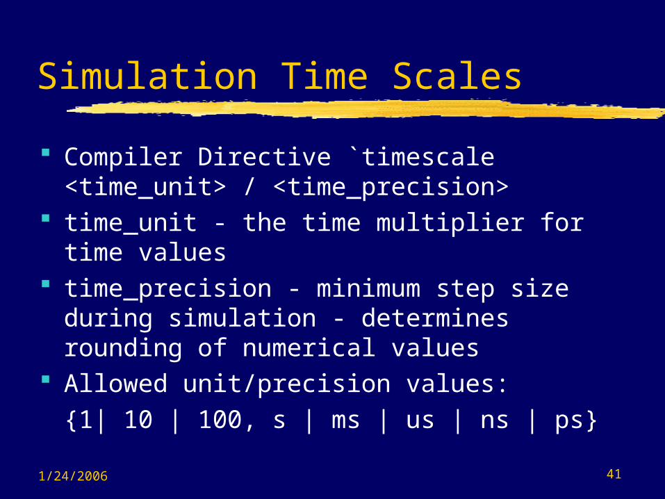
Simulation Time Scales
Compiler Directive `timescale <time_unit> / <time_precision>
time_unit - the time multiplier for time values
time_precision - minimum step size during simulation - determines rounding of numerical values
Allowed unit/precision values: {1| 10 | 100, s | ms | us | ns | ps}

1/24/2006 42
Example: `timescale 10ps / 1ps nor #3.57 (z, x1, x2);nor delay used = 3.57 x 10 ps = 35.7 ps => 36 ps
Different timescales can be used for different sequences of modules
The smallest time precision determines the precision of the simulation.
Simulation Time Scales (continued)

1/24/2006 43
Behavioral Constructs
Concurrent communicating behaviors => processes same as behaviors
Two constructs• initial - one-time sequential activity flow - not
synthesizable but good for testbenches• Always - cyclic (repetitive) sequential activity
flow
Use procedural statements that assign only register variables (with one exception)
1/24/2006 44
Behavioral Constructs (continued)
Continuous assignments and primitives assign outputs whenever there are events on the inputs
Behaviors assign values when an assignment statement in the activity flow executes. Input events on the RHS do not initiate activity - control must be passed to the statement.

1/24/2006 45
Behavioral Constructs (continued)
Body may consist of a single statement or a block statement
A block statement begins with begin and ends with end
Statements within a block statement execute sequentially
Behaviors are an elaborate form of continuous assignments or primitives but operate on registers (with one exception) rather than nets
1/24/2006 46
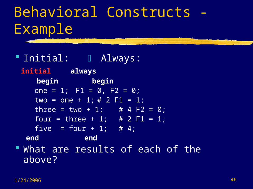
Behavioral Constructs - Example
Initial: Always: initial always begin begin
one = 1; F1 = 0, F2 = 0; two = one + 1; # 2 F1 = 1; three = two + 1; # 4 F2 = 0; four = three + 1; # 2 F1 = 1; five = four + 1; # 4; end end
What are results of each of the above?

1/24/2006 47
Procedural Assignments
Types • = blocking assignment• assign = continuous assignment• <= non-blocking assignment
Assignments (with one exception) to:• reg• integer• real• realtime• time
1/24/2006 48
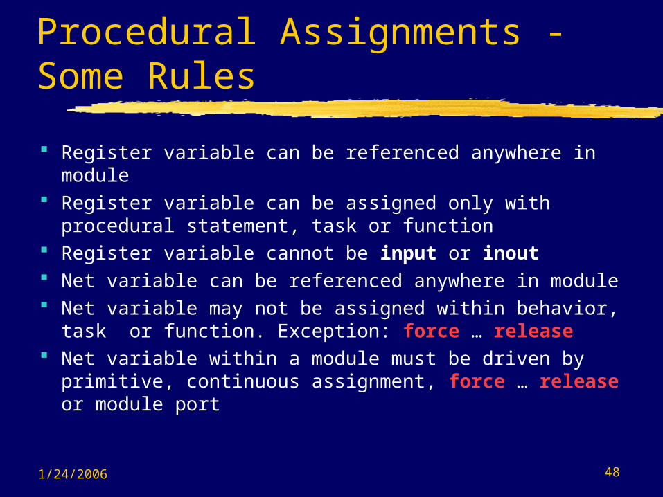
Procedural Assignments - Some Rules
Register variable can be referenced anywhere in module
Register variable can be assigned only with procedural statement, task or function
Register variable cannot be input or inout Net variable can be referenced anywhere in module Net variable may not be assigned within behavior,
task or function. Exception: force … release Net variable within a module must be driven by
primitive, continuous assignment, force … release or module port

1/24/2006 49
Procedural Timing, Controls & Synchronization
Mechanisms• Delay Control Operator (#)• Event Control Operator (@)*• Event or• Named Events – not used much• wait construct
*Ignored by FPGA express unless a synchronous trigger that infers a register
1/24/2006 50
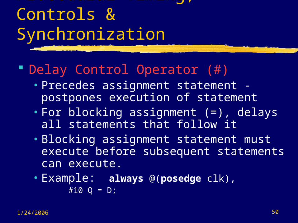
Procedural Timing, Controls & Synchronization
Delay Control Operator (#)• Precedes assignment statement -
postpones execution of statement• For blocking assignment (=), delays all
statements that follow it• Blocking assignment statement must
execute before subsequent statements can execute.
• Example: always @(posedge clk),#10 Q = D;

1/24/2006 51
Procedural Timing, Controls & Synchronization
Event Control Operator (@)*• Synchronizes the activity flow of a behavior to an event
(change) in a register or net variable or expression• Example 1: @ (start) RegA = Data;• Example 2: @(toggle) begin
…
@ (posedge clk) Q = D; … end
*Ignored by FPGA express unless a synchronous trigger that infers a register
1/24/2006 52
Procedural Timing, Controls & Synchronization
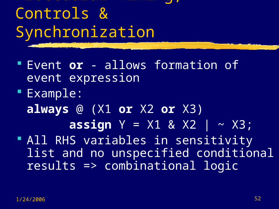
Event or - allows formation of event expression
Example:always @ (X1 or X2 or X3) assign Y = X1 & X2 | ~ X3;
All RHS variables in sensitivity list and no unspecified conditional results => combinational logic

1/24/2006 53
Procedural Timing, Controls & Synchronization
Meaning of posedge: 0 -> 1, 0 -> x, x -> 1
Special Example:always @ (set or reset or posedge clk) begin
if (reset == 1) Q = 0; else if (set == 1) Q = 1; else if (clk == 1) Q = data;
end// Does this work correctly? Why or why not?
1/24/2006 54
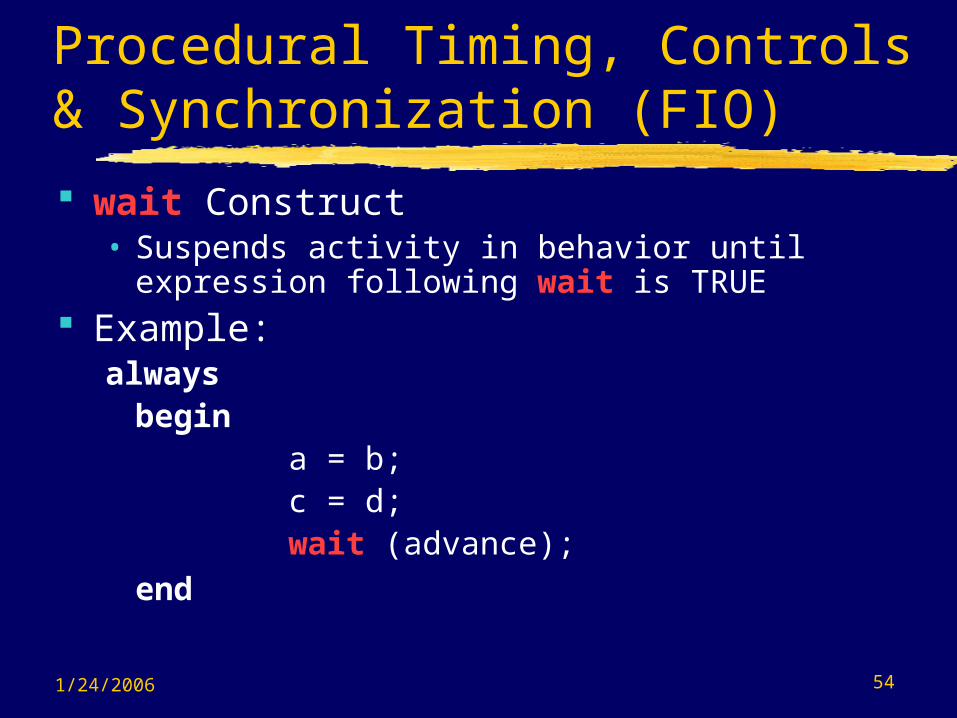
Procedural Timing, Controls & Synchronization (FIO)
wait Construct• Suspends activity in behavior until expression
following wait is TRUE Example:
alwaysbegin
a = b; c = d; wait (advance);
end

1/24/2006 55
Blocking Assignments Identified by = Sequence of blocking assignments executes
sequentially Example: always @(posedge clk)
begin b = 0; c = 0; b = a + a;
c = b + a; d = c + a;end

1/24/2006 56
Non-Blocking Assignments Identified by <= Sequence of non-blocking assignments executes
concurrently Example 1:
always @(posedge clk) begin
b <= 0; c <= 0;b <= a + a; c <= b + a; d <= c + a; end
/*Calculates b = 2a, c = b + a, d <= c + a. All values used on RHS are those at posedge clock. Note that there are two assignments to b and c. Only the last one is effective. */

1/24/2006 57
Blocking Assignments - Inter-Assignment Delay
Delays evaluation of RHS and assignment to LHS
Example: always @(posedge clk)
beginb = 0; c = 0;b = a + a; // uses a at posedge clock
#5 c = b + a; // uses a at posedge clock + 5d = c + a; // uses a at posedge clock + 5
end /*c = 2 a(at posedge clock)+ a(at posedge clock + 5) d = 2 a(at posedge clock) + 2 a(at posedge
clock + 5)*/

1/24/2006 58
Delays assignment to LHS and subsequent statements, not evaluation of RHS
Example: always @(posedge clk)
beginb = 0; c = 0;b = a + a; // uses a at posedge clockc = #5 b + a; // uses a at posedge clock d = c + a; // uses a at posedge clock +
5 end /* c = 3 a(at posedge clock) d = 3a (at posedge clock)+ a (at posedge clock + 5)*/
Blocking Assignment - Intra-Assignment Delay
1/24/2006 59
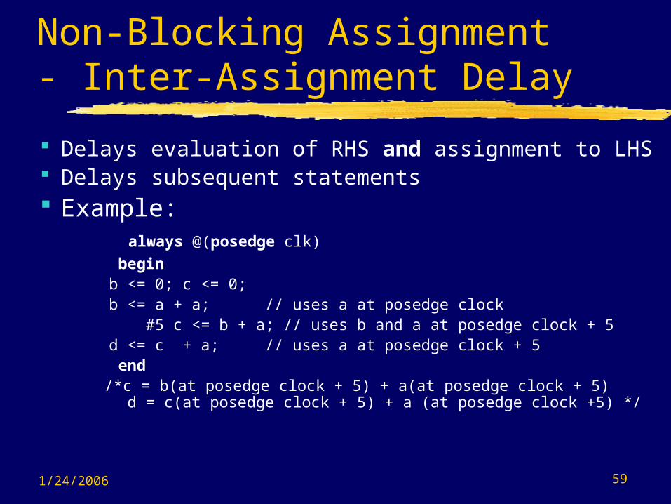
Non-Blocking Assignment - Inter-Assignment Delay
Delays evaluation of RHS and assignment to LHS Delays subsequent statements Example: always @(posedge clk)
beginb <= 0; c <= 0;b <= a + a; // uses a at posedge clock
#5 c <= b + a; // uses b and a at posedge clock + 5d <= c + a; // uses a at posedge clock + 5
end /*c = b(at posedge clock + 5) + a(at posedge clock + 5) d =
c(at posedge clock + 5) + a (at posedge clock +5) */
1/24/2006 60
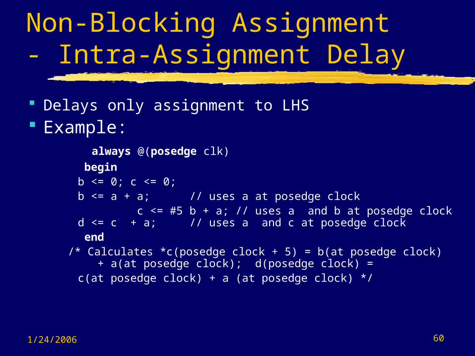
Non-Blocking Assignment - Intra-Assignment Delay
Delays only assignment to LHS Example: always @(posedge clk)
beginb <= 0; c <= 0;b <= a + a; // uses a at posedge clock
c <= #5 b + a; // uses a and b at posedge clock d <= c + a; // uses a and c at posedge
clock end
/* Calculates *c(posedge clock + 5) = b(at posedge clock) + a(at posedge clock); d(posedge clock) =c(at posedge clock) + a (at posedge clock) */

1/24/2006 61
Activity ControlOverview Constructs for Activity Control
• Conditional operator• case statement• if … else statement• Loops : repeat, for, while, forever• disable statement• fork … join statement
Tasks and Functions

1/24/2006 62
Conditional Operator
? … : Same as for use in continuous
assignment statement for net types except applied to register types
Example:always@(posedge clock)
Q <= S ? A : B //combined DFF and 2-to-1 MUX
1/24/2006 63
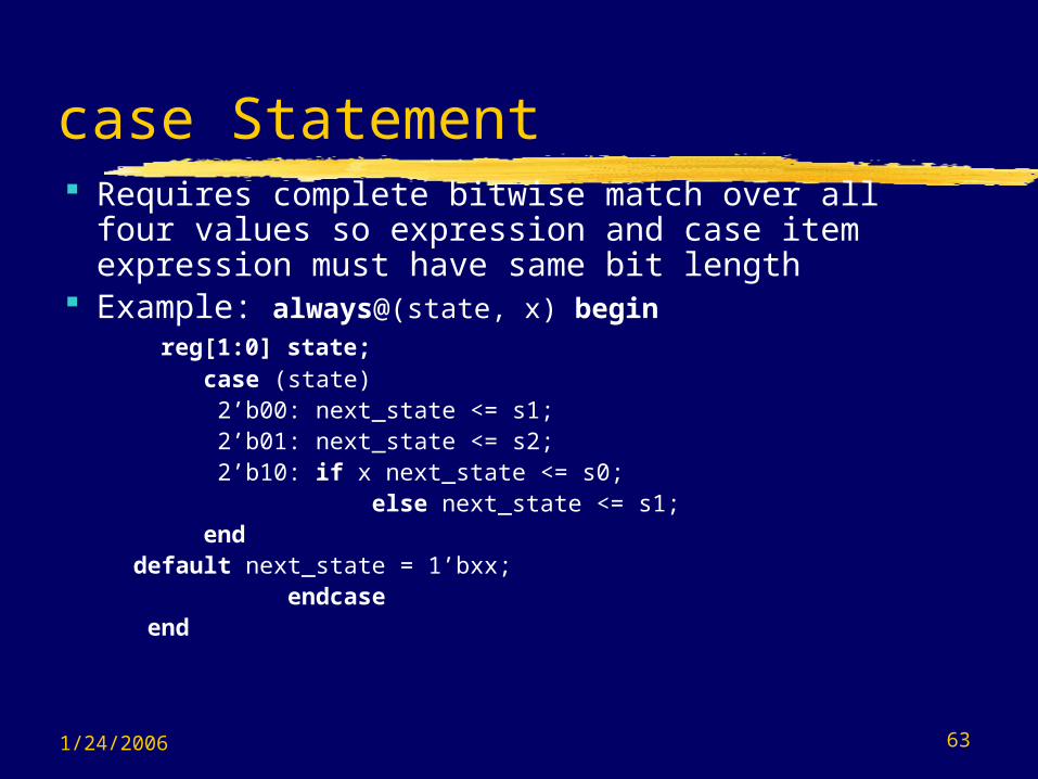
case Statement Requires complete bitwise match over all four
values so expression and case item expression must have same bit length
Example: always@(state, x) begin reg[1:0] state;
case (state) 2’b00: next_state <= s1;
2’b01: next_state <= s2; 2’b10: if x next_state <= s0; else next_state <= s1;
enddefault next_state = 1’bxx;
endcase end

1/24/2006 64
casex Statement Requires bitwise match over all but positions
containing x or z; executes first match encountered if multiple matches.
Example:always@(code) begin
casex (code) 2’b0x: control <= 8’b00100110; //same for 2’b0z2’b10: control <= 8’b11000010;2’b11: control <= 8’b00111101; default control <= 8b’xxxxxxxx;
endcaseend
1/24/2006 65
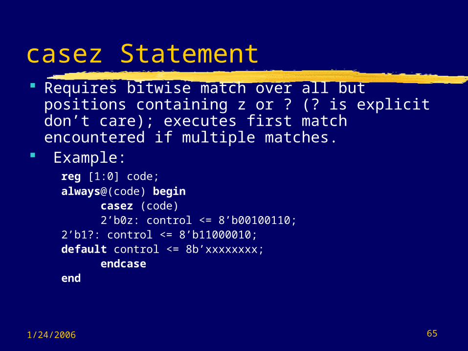
casez Statement Requires bitwise match over all but positions
containing z or ? (? is explicit don’t care); executes first match encountered if multiple matches.
Example:reg [1:0] code;always@(code) begin
casez (code) 2’b0z: control <= 8’b00100110;
2’b1?: control <= 8’b11000010;default control <= 8b’xxxxxxxx;
endcaseend
1/24/2006 66
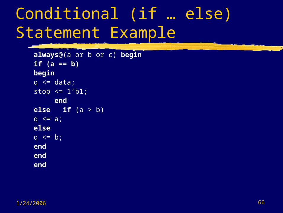
Conditional (if … else) Statement Example
always@(a or b or c) beginif (a == b)
beginq <= data;stop <= 1’b1;
endelse if (a > b)
q <= a;else
q <= b;end
endend

1/24/2006 67
Conditional (if … else) Statement (continued)
Must be careful to define outcome for all possible conditions – failure do do so can cause unintentional inference of latches!
else is paired with nearest if when ambiguous - use begin and end in nesting to clarify.
Nested if … else will generate a “serial” or priority like circuit in synthesis which may have a very long delay - better to use case statements to get “parallel” circuit.
1/24/2006 68
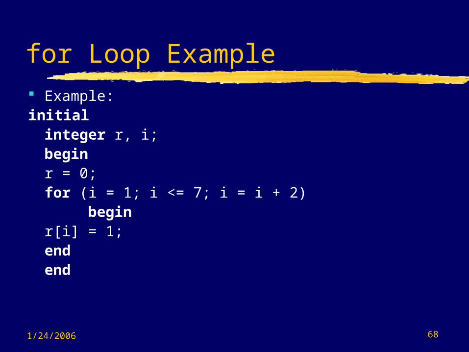
for Loop Example Example:initial
integer r, i;begin
r = 0; for (i = 1; i <= 7; i = i + 2)
beginr[i] = 1;
end end
1/24/2006 69
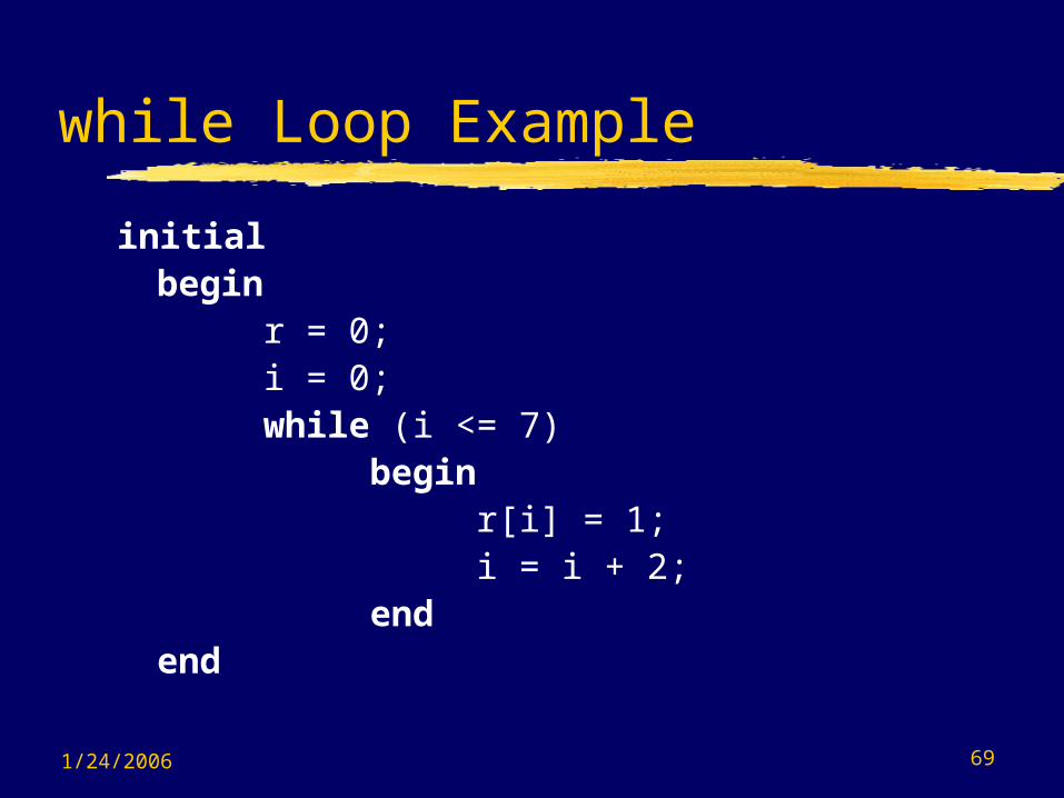
while Loop Example
initialbegin
r = 0; i = 0;while (i <= 7)
beginr[i] = 1;i = i + 2;
end end

1/24/2006 70
forever Loop Example
initialbegin
clk = 0; forever
begin#50 clk = 1;#50 clk = 0;
end end
Usually used in testbenches rather than for synthesized logic.

1/24/2006 71
Tasks Declared within a module Referenced only by a behavior within the module Parameters passed to task as inputs and inouts
and from task as outputs or inouts Local variables can be declared Recursion not supported although nesting
permitted (nested copies of variables use same storage)
See Fig. 7.43 p. 226 of [5]for rules
1/24/2006 72
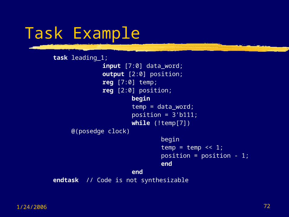
Task Exampletask leading_1;
input [7:0] data_word; output [2:0] position; reg [7:0] temp; reg [2:0] position; begin temp = data_word; position = 3'b111; while (!temp[7])
@(posedge clock) begin temp = temp << 1; position = position - 1; end end
endtask // Code is not synthesizable

1/24/2006 73
Functions
Implement combinational behavior No timing controls or tasks which implies no
while May call other functions with no recursion Reference in an expression, e.g. RHS No output or inout allowed Implicit register having name and range of
function

1/24/2006 74
Function Example
function [2:0] leading_1; input [7:0] data_word;
reg [7:0] temp; begin
temp = data_word; leading_1 = 3'b111; while (!temp[7]) begin temp = temp << 1; leading_1 = leading_1 - 1; end end
endfunction Is the above code synthesizable?
No

1/24/2006 75
Compiler Directives
Useful for controlling what is synthesized and the resulting logic
Warning: Not recognized by other compilers – therefore reduce code portability
Examples:• // synopsys translate_off
Code here describes something that is not to be synthesized such at a simulation testbench -can contain non-synthesizable constructs such as delays)
// synopsys translate_on
1/24/2006 76
Compiler Directives (Continued)
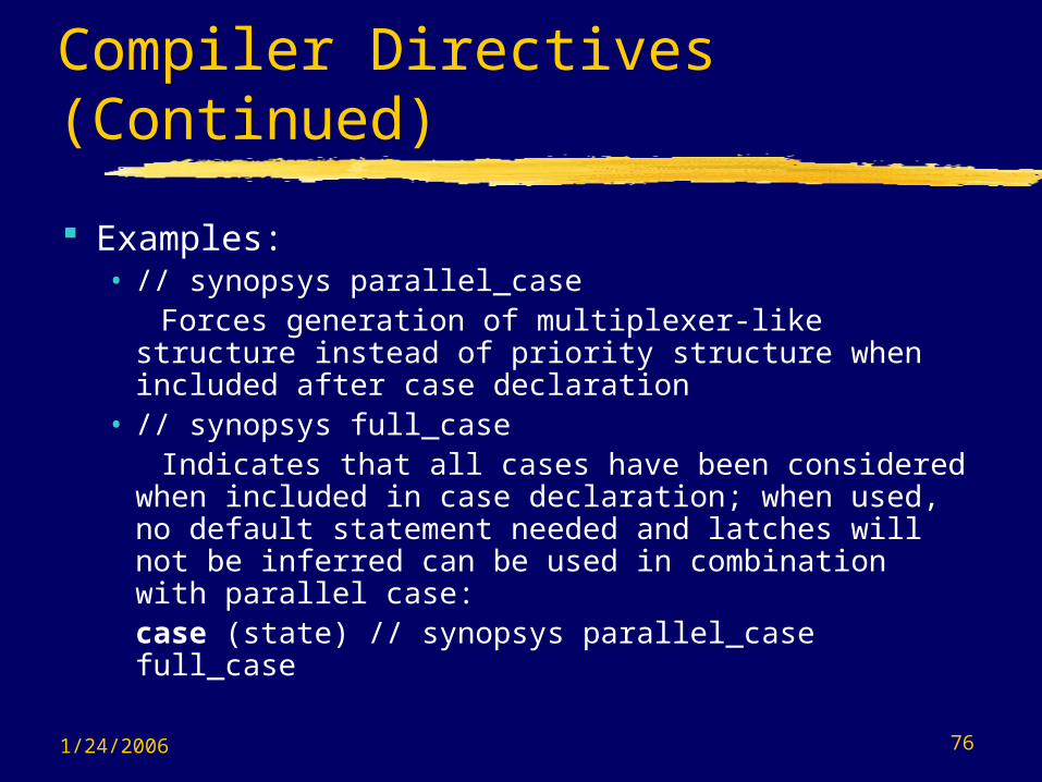
Examples:• // synopsys parallel_case Forces generation of multiplexer-like structure
instead of priority structure when included after case declaration
• // synopsys full_case Indicates that all cases have been considered
when included in case declaration; when used, no default statement needed and latches will not be inferred can be used in combination with parallel case:case (state) // synopsys parallel_case full_case
1/24/2006 77
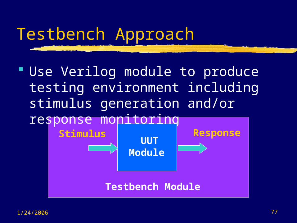
Testbench Approach
Use Verilog module to produce testing environment including stimulus generation and/or response monitoring
UUTModule
Stimulus Response
Testbench Module
1/24/2006 78
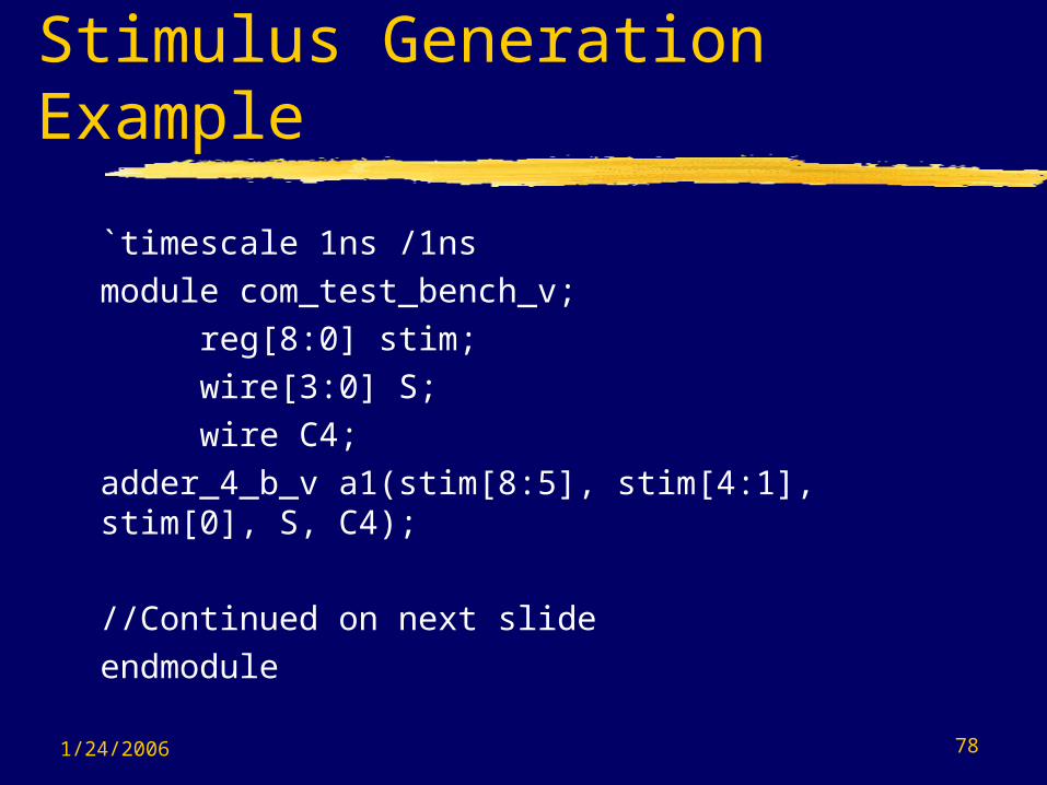
Stimulus Generation Example
`timescale 1ns /1nsmodule com_test_bench_v;
reg[8:0] stim; wire[3:0] S; wire C4;
adder_4_b_v a1(stim[8:5], stim[4:1], stim[0], S, C4);
//Continued on next slideendmodule
1/24/2006 79
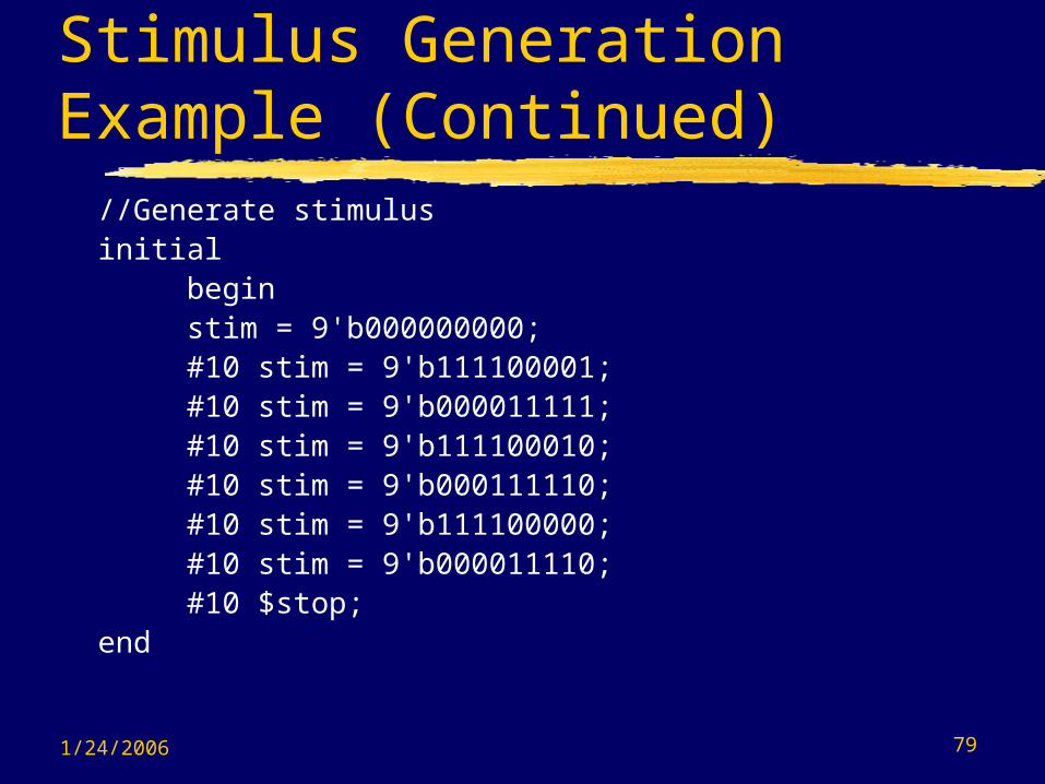
Stimulus Generation Example (Continued)
//Generate stimulusinitial
begin stim = 9'b000000000; #10 stim = 9'b111100001; #10 stim = 9'b000011111; #10 stim = 9'b111100010; #10 stim = 9'b000111110; #10 stim = 9'b111100000; #10 stim = 9'b000011110; #10 $stop;
end
1/24/2006 80
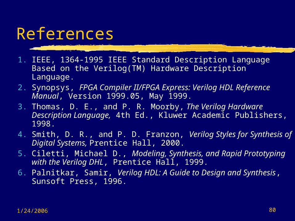
References1. IEEE, 1364-1995 IEEE Standard Description Language
Based on the Verilog(TM) Hardware Description Language.2. Synopsys, FPGA Compiler II/FPGA Express: Verilog HDL
Reference Manual, Version 1999.05, May 1999.3. Thomas, D. E., and P. R. Moorby, The Verilog Hardware
Description Language, 4th Ed., Kluwer Academic Publishers, 1998.
4. Smith, D. R., and P. D. Franzon, Verilog Styles for Synthesis of Digital Systems, Prentice Hall, 2000.
5. Ciletti, Michael D., Modeling, Synthesis, and Rapid Prototyping with the Verilog DHL, Prentice Hall, 1999.
6. Palnitkar, Samir, Verilog HDL: A Guide to Design and Synthesis, Sunsoft Press, 1996.


