
12/06/200312/06/2003 11
Direct-Off-Line Single-Ended Direct-Off-Line Single-Ended Forward ConvertersForward Converters
andandThe Right-Half-Plane ZeroThe Right-Half-Plane Zero
Presented by:Presented by:
Geetpal KaurGeetpal Kaur
EE136 StudentEE136 Student
12/06/200312/06/2003 22
Direct-Off-Line Single-Ended Direct-Off-Line Single-Ended Forward ConverterForward Converter
The power stage of a typical The power stage of a typical single-ended forward convertersingle-ended forward converter
Ls carries a large DC current Ls carries a large DC current componentcomponent
The term “Choke” is used to The term “Choke” is used to describe this componentdescribe this component
The general appearance of the The general appearance of the power stage is similar to the power stage is similar to the flyback unitflyback unit

12/06/200312/06/2003 33
Forward converter with energy Forward converter with energy recovery windingrecovery winding

12/06/200312/06/2003 44
Operating PrinciplesOperating Principles
When transistor Q1 turns onWhen transistor Q1 turns on
Supply voltage Vcc is applied to Supply voltage Vcc is applied to the primary winding P1the primary winding P1
As a result a secondary voltage As a result a secondary voltage Vs is developed and applied to Vs is developed and applied to output rectifier D1 and choke Lsoutput rectifier D1 and choke Ls

12/06/200312/06/2003 55
Operating PrinciplesOperating Principles
The voltage across the choke Ls The voltage across the choke Ls will be Vs less the output voltage will be Vs less the output voltage VoutVout
The current in Ls will increase The current in Ls will increase linearly linearly
di / dt = (Vs – Vout) / Lsdi / dt = (Vs – Vout) / Ls

12/06/200312/06/2003 66
Operating PrinciplesOperating Principles
At the end of an on periodAt the end of an on period
Q1 will turn offQ1 will turn off
Secondary voltages will reverseSecondary voltages will reverse
Choke current IChoke current ILL will continue to will continue to flow in the forward directionflow in the forward direction

12/06/200312/06/2003 77
Operating PrinciplesOperating Principles
As a result diode D2 will turn onAs a result diode D2 will turn on
D2 allows the current to D2 allows the current to continue circulating in the loop continue circulating in the loop D2, Ls, Co, and loadD2, Ls, Co, and load
The voltage across the choke Ls The voltage across the choke Ls will reversewill reverse

12/06/200312/06/2003 88
Operating PrinciplesOperating Principles
The current in Ls will decreseThe current in Ls will decrese -di / dt = Vout / Ls-di / dt = Vout / Ls

12/06/200312/06/2003 99
Output VoltageOutput Voltage
VVoutout = (V = (Vss * t * tonon) / (t) / (tonon + t + toffoff))
Vs = secondary voltage, peak VVs = secondary voltage, peak V
ton = time that Q1 is conduction, ton = time that Q1 is conduction, µsµs
12/06/200312/06/2003 1010
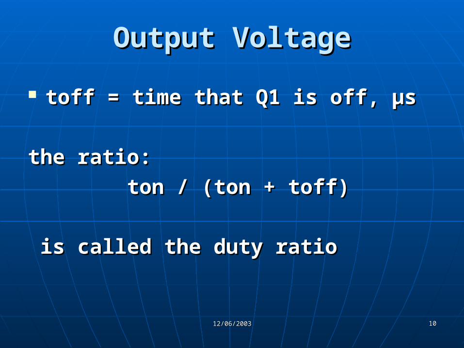
Output VoltageOutput Voltage
toff = time that Q1 is off, µstoff = time that Q1 is off, µs
the ratio:the ratio:
ton / (ton + toff)ton / (ton + toff)
is called the duty ratiois called the duty ratio

12/06/200312/06/2003 1111
Circuit SimulationCircuit Simulation

12/06/200312/06/2003 1212
The Right-Half-Plane ZeroThe Right-Half-Plane Zero
The difficulty of obtaining a The difficulty of obtaining a good stability margin and good stability margin and high-frequency transient high-frequency transient performance from the performance from the continuous-inductor-mode continuous-inductor-mode flyback and boost convertersflyback and boost converters

12/06/200312/06/2003 1313
Causes of the RHP ZeroCauses of the RHP Zero
A negative zero in the small-A negative zero in the small-signal duty cycle control to signal duty cycle control to output transfer functionoutput transfer function
The negative sign locates this The negative sign locates this zero in the right half of the zero in the right half of the complex frequency planecomplex frequency plane

12/06/200312/06/2003 1414
The RHP ZeroThe RHP ZeroA simplified ExplanationA simplified Explanation
The right-half-plane (RHP) zero The right-half-plane (RHP) zero has the same 20dB/decade rising has the same 20dB/decade rising gain magnitude as a gain magnitude as a conventional zero, but with 90º conventional zero, but with 90º phase lag instead of lead phase lag instead of lead

12/06/200312/06/2003 1515
Effects of Increasing Duty RatioEffects of Increasing Duty Ratio
The peak inductor current The peak inductor current increases in each switching cycleincreases in each switching cycle
The diode conduction time The diode conduction time decreasesdecreases
This is the circuit effect which is This is the circuit effect which is mathematically the RHP Zeromathematically the RHP Zero

12/06/200312/06/2003 1616
The RHP ZeroThe RHP ZeroA simplified ExplanationA simplified Explanation
12/06/200312/06/2003 1717
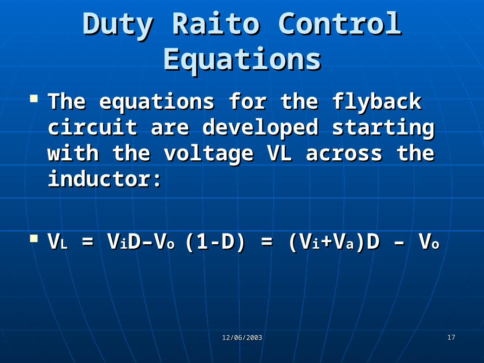
Duty Raito Control EquationsDuty Raito Control Equations
The equations for the flyback The equations for the flyback circuit are developed starting circuit are developed starting with the voltage VL across the with the voltage VL across the inductor:inductor:
VVLL = V = ViiD–VD–Vo o (1-D) = (V(1-D) = (Vii+V+Vaa)D – V)D – Voo

12/06/200312/06/2003 1818
Duty Raito Control EquationsDuty Raito Control Equations
Modulating the duty ratio D by a Modulating the duty ratio D by a small AC signal d whose small AC signal d whose frequency is much smaller than frequency is much smaller than the switching frequency the switching frequency generated an ac inductor voltage generated an ac inductor voltage ννLL::
ννLL = (Vi + Va)d – = (Vi + Va)d – ννo(1-D) =o(1-D) =
(Vi + Vo)d (Vi + Vo)d

12/06/200312/06/2003 1919
Duty Raito Control EquationsDuty Raito Control Equations
RHP zero frequency:RHP zero frequency:
ωωz z = Vi / L IL= Vi / L IL
12/06/200312/06/2003 2020
Current-Mode Control EquationsCurrent-Mode Control Equations
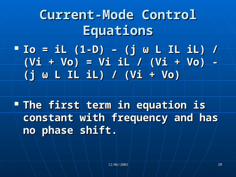
Io = iL (1-D) – (j Io = iL (1-D) – (j ωω L IL iL) / (Vi + L IL iL) / (Vi + Vo) = Vi iL / (Vi + Vo) - (j Vo) = Vi iL / (Vi + Vo) - (j ωω L IL L IL iL) / (Vi + Vo)iL) / (Vi + Vo)
The first term in equation is The first term in equation is constant with frequency and has constant with frequency and has no phase shift.no phase shift.
12/06/200312/06/2003 2121
Current-Mode Control EquationsCurrent-Mode Control Equations
This term dominates at low This term dominates at low frequency. frequency.
It represents the small-signal It represents the small-signal inductor current, which is inductor current, which is maintained constant by the inner maintained constant by the inner current control loop, thus current control loop, thus eliminating the inductor pole.eliminating the inductor pole.

12/06/200312/06/2003 2222
Current-Mode Control EquationsCurrent-Mode Control Equations
It dominates at frequencies It dominates at frequencies above ωz where the magnitudes above ωz where the magnitudes of the two terms are equal. of the two terms are equal.
The RHP zero frequency ωz may The RHP zero frequency ωz may be calculated by equating the be calculated by equating the two terms of equation (9.9). two terms of equation (9.9).

12/06/200312/06/2003 2323
Current-Mode Control EquationsCurrent-Mode Control Equations
The second term increases with The second term increases with frequency, yet the phase lags by frequency, yet the phase lags by 90º, characteristic of the RHP 90º, characteristic of the RHP zero. zero.


![[IJCST-V3I5P1]: Er. Jashandeep Kaur, Er.Rupinder Kaur Gurm](https://cdn.vdocuments.us/doc/165x107/563dba34550346aa9aa393e2/ijcst-v3i5p1-er-jashandeep-kaur-errupinder-kaur-gurm.jpg)


