
Block-ZylinderNenndruck: 400barPrüfdruck: 600barMax. Hub: 500mmKolben Ø: 16 bis 100mmEinsatzgebiet:• Formenbau• Werkzeugbau• VorrichtungsbauEndlagenabfrage: als BLZNI400
Block cylinder
Nominal pressure: 400bar
Test pressure: 600bar
Max. stroke: 500mm
Piston Ø: 16 to 100mm
Application area:
• Mould-making
• Tool manufacturing
• Fixture construction
Sensing of end position: as BLZNI400
Vérin bloc
Pression nominale: 400 bar
Pression de contrôle: 600 bar
Max. Course: 500 mm
Piston Ø: 16 à 100mm
Domain d’utilisation:
• Construction de moulages
• Construction d’outillage
• Construction de fixations
Détection de fin de course: en BLZNI400
Hydraulik-BlockzylinderBlock cylindersVérins blocs
BLZ400-05-2014
BLZ400BLZNI400
HEB Hydraulik-Elementebau GmbH
[email protected], www.heb-zyl.com

Allgemeine Beschreibungund Hinweise
Bauweise:
Blockzylinder mit sehr kleinenBaulängen
Kolbenstangenlauffläche hartver-chromt, geschliffen und poliert
Kolben-Ø und Kolbenstangen-Ønach DIN/ISO 3320
Hübe (Hubtoleranz DIN/ISO 2768m)nach Kundenwunsch 0,1mm bis500mm oder Standardhübe (S.4)
Bei großen Hublängen ist die maxi-mal mögliche Hublänge zu beachten
Abfrage:
Der BLZNI400 ist serienmäßig soausgelegt, dass nur bei Erreichender Hubendlage ein Schaltimpulsabgegeben wird (d.h. der Zylindermuss den angegebenen Hub voll-ständig fahren können)
Eine Schaltpunktvorverlagerungstangen- und/oder kolbenseitig umbis zu 5mm auf Kundenwunschohne Maßänderung möglich (d.h.Zylinderhub wird zwar voll ausge-nutzt, der Schaltimpuls stehtjedoch entsprechend dem vorver-legten Schaltpunkt schon vorherzur Verfügung).Durch folgenden Zusatz zur Bestell-bezeichnung kann eine gewünschteSchaltpunktverlagerung kenntlichgemacht werden:SPS3* = Schaltpunkt stangenseitig3mm vor EndlageSPK3* = Schaltpunkt kolbenseitig3mm vor EndlageSPB3* = Schaltpunkt beidseitig3mm vor Endlage(* Schaltpunktverlagerung 1-5mmeinsetzen)
Die Wiederholgenauigkeit liegt bei0,05mm
Zur Vermeidung von Fehlschaltun-gen (Hysterese) ist ein Mindesthubvon 3mm einzuhalten
Ein nachträgliches Verstellen deseinmal festgelegten Schaltpunktesist nicht möglich
HEB Hydraulik-Elementebau GmbH / Tel. (0761) 13 0 99-0, Fax (0761) 13 50 662
General description and
informations
Construction:
Block cylinders with very small
lengths
Piston-rod hard-chrome plated,
ground and polished
Piston-Ø and Piston-rod-Ø according
to DIN/ISO 3320
Strokes (Stroke tolerance according to
DIN/ISO 2768m) according to custo-
mer request 0,1mm to 500mm or stan-
dard strokes (p.4)
With large strokes consider the maxi-
mum stroke
Query:
The BLZNI400 is equiped in series so
that a sensing impulse is only given if it
reaches the end of stroke (that means,
the cylinder must be able to execute
the indicated total stroke)
The sensing point shift piston-rod
and/or piston side by up to 5mm on
request without dimensional change is
possible (that means, in this case, the
cylinder stroke is fully utilized but cor-
responding to the displaced sensing
point, the sensing impulse is available
before).
A displacement of the sensing point
can be marked by the following sup-
plement:
SPS3* = sensing point rod-side 3mm
before stroke end
SPK3* = sensing point piston-side
3mm before stroke end
SPB3* = sensing point both-side 3mm
before stroke end
(* enter the desired displacement of the
sensing point from 1-5mm)
The repeat accuracy is 0,05mm
To avoid faulty switching (hysteresis) a
minimum stroke of 3mm has to be
considered
The once fixed sensing point cannot be
displaced subsequently
Description générale et des
informations
Construction:
Vérins-bloc avec des longueurs très
petites
Tige de piston chromées durement,
meulées et polies
Ø-piston et Ø-tige de piston selon
DIN/ISO 3320
Course (Tolérance de course confor-
mes à la norme DIN/ISO 2768m) selon
la demande du client 0,1 mm à 500mm
ou course standardisées (p.4)
Avec de grandes courses considérer le
maximum course est observée
Détection:
Le BLZNI400 est équipé en série de
sorte que l'impulsion de détection n'est
donné que si elle atteint la fin de la
course (ce qui signifie, le cylindre doit
être capable d'exécuter le coup indi-
quée au total)
Un déplacement du point de détection
côté tige et/ou côté piston est possible
jusqu´à 5 mm selon le souhait du client
(c´est à dire la course du cylindre est
en effet entièrement utilisée, mais
l´impulsion de détection est disponible
déjà avant correspondant le déplace-
ment du point de détection).
Si vous souhaitez un déplacement du
point de commutation il faut ajouter à la
référence de commande une phrase
supplémentaire telle que la suivante:
SPS3* = point de détection côté tige
3 mm avant la fin de course
SPK3* = point de détection côté piston
3 mm avant la fin de course
SPB3* = point de détection aux deux
côtés 3mm avant la fin de course
(* Entrer dans le déplacement souhaité
du point de détection de 1 à 5mm)
La précision de répétition est de
0,05 mm
Pour éviter faux couplage (hystèrèsis) il
faut observer une course minimale de
3 mm
Il n'est pas possible de régler le point
de détection aprés qu'il à eté déter-
miné une fois
•
•
•
•
•
•
•
•
•
•
BLZ400

•
•
•
•
•
•
•
BLZ400
Allgemeine Beschreibungund Hinweise
Kolbengeschwindigkeit:
Für höhere Geschwindigkeiten isteine Änderung der Anschlussgrößenund eine Endlagendämpfung oderexterne Hubbegrenzung notwendig(Bitte kontaktieren Sie uns)
Die Endlagendämpfung mit progres-sivem Übergang in die Dämpfungs-phase ist grundsätzlich ab Kolben-Ø20mm lieferbar
Dichtung:
Die Kolbenstangendichtung bestehtstandardmäßig aus einem PU-Nutring (weitere Dichtungsvariantenauf Anfrage)
Die Kolbendichtung besteht stan-dardmäßig aus PTFE und ist beson-ders reibungsarm, alternativ für sta-tische Dichtheit gibt es eine spezielleDichtung (S35)
Die Standarddichtungen sind fürHydroflüssigkeiten der Typen H, HL,HLP nach DIN 51524 / 51525 und denTemperaturbereich von -20°C bis+90°C geeignet
Beim Betrieb mit anderen Druckflüs-sigkeiten oder höheren Temperatu-ren sind andere Dichtungswerkstoffeerforderlich (bitte beachten Sieunsere Sonderaussattungen oderkontaktieren Sie uns)
Grundsätzlich erhältlich sind verän-derte Bauformen, Zylinder mit Küh-lung sowie Sonderanfertigungennach Kundenwunsch - bitte kontak-tieren Sie uns
e-mail: [email protected] / homepage: http://www.heb-zyl.com 3
General description and
informations
Piston speed:
For higher speeds is a change of
dimensions of connections and a stro-
ke-end damping or external stroke limi-
tation are required (please contact us)
The stroke-end damping with progres-
sive transition to damping phase avai-
lable for piston-Ø above 20mm
Seal:
The piston rod seal typically consists of
a PU-ring in groove (other seals on
request)
The piston seal typically consists of
PTFE and is extremely low friction, as
an alternative for static sealing there is
a special seal (S35)
The standard seals are suitable to
hydraulic fluids of the type H, HL, HLP
according to DIN51524/51525 and to
temperatures from -20°C to +90°C
For operation with other fluids or higher
temperatures, other sealing materials
are required (please note our special
equipment or contact us)
Generally available are altered designs,
cylinder with cooling as well as custom
made cylinders - please contact us
Description générale et des
informations
Vitesse du piston:
Pour des vitesses supérieures est un
changement de dimensions de conne-
xions et un amortissement de fin de
course ou externe limitation de course
sont nécessaires (s'il vous plaît contac-
tez-nous)
L´amortissement en fin de course avec
survenance progressif dans la phase
d´amortissement est principalement
livrable à partir d´un piston ø 20mm
Joint:
Le joint de tige se compose générale-
ment d'un PU-anneau (autres joints sur
demande)
Le joint de piston se compose
généralement de PTFE et de frottement
extrêmement faible, comme une alter-
native pour étanchéité statique est un
sceau spécial (S35)
Les joints standard sont concus pour
de fluides hydrauliques des types H,
HL, HLP conformément aux normes
DIN51524/51525 et pour des tempéra-
tures de -20°C à +90°C
Pour le fonctionnement avec d'autres
fluids hydrauliques ou des températu-
res plus élevées, autres matériaux
d'étanchéité sont requis (s'il vous plaît
noter que notre équipement spécial ou
contactez-nous)
Généralement disponibles sont modi-
fiées conçoit, cylindre à refroidisse-
ment ainsi que les bouteilles fabriquées
sur mesure - s'il vous plaît contactez-
nous

Technische Daten Technical data Caractéristiques techniques
HEB Hydraulik-Elementebau GmbH / Tel. (0761) 130 99-0, Fax (0761) 13 50 664 BLZ400
Kolben - Ø mm 16 20 25 32 40 50 63
Piston - Ø mm • Ø - piston mm
Baureihe BLZ BLZNI BLZ BLZNI BLZ BLZNI BLZ BLZNI BLZ BLZNI BLZ BLZNI BLZ BLZNI
Construction • Construction Hübe
strokes • courses
10 ● ● ● ●
15 ● ● ● ● ● ● ● ● ● ● ● ●
20 ● ● ● ● ● ● ● ● ● ● ● ● ●
25 ● ● ● ● ● ● ● ● ● ● ● ●
30 ● ● ● ● ● ● ● ● ● ● ● ●
40 ● ● ● ● ● ● ● ● ● ● ● ●
50 ● ● ● ● ● ● ● ● ● ● ● ●
60 ● ● ● ● ● ● ●
70 ●
80 ● ● ● ● ●
100 ● ● ● ● ●
Kurze Lieferzeiten durch Standardhübe Funktionsart 200, 201, 206 gemäß Tabelleund Zwischenhübe beim BLZ400 durch Begrenzungshülsen Short delivery time through standard strokes mode of operation 20, 201, 206 according to table
and intermediate strokes when BLZ400 with limiter sleeves
Délai de livraison bref avec courses stadardisées mode de fonctionnement 200, 201, 206 selon table
et entre-courses quand BLZ400 avec douilles de limitation
Kolben - Ø mm 16 20 25 32 40 50 63 80 100
Piston - Ø mm • Ø - piston mm
Kolbenstangen - Ø mm 10 12 16 20 25 32 40 50 60
Piston-rod - Ø mm • Ø - tige de piston mm
Kolbenfläche stoßend - cm2 • Piston area pushing - cm2 • Surface de piston poussante - cm2
2,01 3,14 4,91 8,04 12,56 19,63 31,16 50,24 78,50
Kolbenfläche ziehend cm2 • Piston area pulling - cm2 • surface de piston tirante - cm2
1,22 2,00 2,90 4,90 7,65 11,59 18,60 30,61 50,24
Kolbenkraft stoßend - daN • Piston force pushing - daN • Force de piston poussante - daN
100 bar 201 314 491 804 1256 1963 3116 5024 7850 150 bar 301 471 736 1206 1884 2944 4674 7536 11775 200 bar 402 628 982 1608 2512 3926 6232 10048 15700 300 bar 603 942 1473 2412 3768 5889 9348 15072 23550 400 bar 804 1256 1964 3216 5024 7852 12464 20096 31400
Kolbenkraft ziehend - daN • Piston force pulling - daN • Force de piston tirante - daN
100 bar 122 200 290 490 765 1159 1860 3061 5024 150 bar 183 300 439 735 1147 1738 2790 4591 7536 200 bar 244 400 580 980 1530 2318 3720 6122 10048 300 bar 366 600 870 1470 2295 3477 5508 9183 15072 400 bar 488 800 1160 1960 3060 4636 7440 12244 20096
Dämpfungsweg - 7 7 8 8 8 10 11 12Cushioning path • Course d’amortissement
Kolben - Ø mm 16 20 25 32 40 50 63 80 100
Piston - Ø mm • Ø - piston mm

• Standardlage der Entlüftungsschrauben Zylinderseite siehe helle Markierung • Standard position of the bleeder screws see the bright marking• Position standard des vis de purge voir le marquage de couleur claire
S5
S7
S9
S13
S14
S35
B1
B1.1
M1.1
e-mail: [email protected] / homepage: http://www.heb-zyl.com
Sonderausstattungen Special equipments Equipements optionnels
5BLZ400
S4.120
S10.120
N2
N4
N2.1
N4.1
Mögliche Lage der EntlüftungsschraubenPosition of the bleeder screws
Position des vis de purge
1
2 3 4 2 3 3 4 2 3 4 3 4 2 2 4 2 3 4
2 4 2 4 2 4 - 4 2 2 4 2 4
EntlüftungBleeding
Purge d'air
BLZ400
BLZNI400
1.1
EntlüftungBleeding
Purge d'air
1.2
EntlüftungBleeding
Purge d'air
2 / 2.1 /
3 / 3.1 / 5.1
EntlüftungBleeding
Purge d'air
4.1
EntlüftungBleeding
Purge d'air
6 / 6.1
EntlüftungBleeding
Purge d'air
6.4 / 6.14
EntlüftungBleeding
Purge d'air
7 / 7.1
EntlüftungBleeding
Purge d'air
8 / 8.1
EntlüftungBleeding
Purge d'air
• Hochhitzebeständige Dichtungen für Hydroflüssigkeiten der Typen H, HL, HLP - DIN 51524/51525
und Temperaturen ab +100°C bis +200°C
High heat-resistant seals for hydraulic fluids type H, HL, HLP – German Standard DIN 51524/51525
and for temperatures from +100°C up to +200°C
Garnitures réstistantes aux températures très élevées pour liquides type H, HL, HLP – DIN 51524/51525
et des températures de +100°C jusqu’ à +200°C
• Beidseitige Entlüftungsschrauben für Schlauchanschluß
Bleed screws on both sides for hose connections
Vis de purge d’air, des deux côtés, pour raccord tuyau
• Vom Standard abweichende Leitungsanschlüsse
Non-standard connections
Raccords tuyaux autres que raccords standards
• Kolbenstangenlauffläche gehärtet und hartverchromt
Piston-rod hardened and hard-chrome plated
Tige de piston trempée et chromée durement
• Kolbenstangen aus V2A, Werkstoff 1.4301, hartverchromt
Piston-rod stainless steal, mat. no. 1.4301, hard-chrome plated
Tige du piston en acier inoxydable, matériau numeró 1.4301, chromée durement
• Kolben statisch dicht
Piston with static sealing effect
Piston avec effet hermétique
• Kolbenstangenende mit Außengewinde
Piston-rod end with externall thread
Fin de la tige de piston avec filet extérieur
• Kolbenstangenende mit Außengewinde nach Kundenwunsch (Bitte L3, L4, d2G angeben)
Piston-rod end with external thread according to the wishes of the customer (please indicate L3, L4, d2G)
Fin de la tige de piston avec filet extérieur selon la demande du client (s'il vous plaît indiquez L3, L4, d2G)
• Kolbenstangenende mit Innengewinde nach Kundenwunsch (Bitte a4, a5, a6 angeben)
Piston-rod end with internal thread according to the wishes of the customer (please indicate a4, a5, a6)
Fin de la tige de piston avec filet intérieur selon la demande du client (s'il vous plaît indiquez a4, a5, a6)
• Nut zur Justierung auf Seite 2 (N2) und/oder auf Seite 4 (N4)
Groove for adjustment on page 2 (N2) and/or on page 4 (N4)
Rainure pour ajustement à la page 2 (N2) et/ou à la page 4 (N4)
• Nut zur Justierung auf Seite 2 (N2) und/oder auf Seite 4 (N4) nach Kundenwunsch (Bitte h, b, t angeben)
Groove for adjustment on page 2 (N2) and/or on page 4 (N4) to the wishes of the customer (Please indicate h, b, t)
Rainure pour ajustement à la page 2 (N2) et/ou à la page 4 (N4) désir du client (S'il vous plait indiquez h, b, t)• Stangenseitiger Zentrierbund
Rod-side with centering collar ZE
Côté tige avec collet de centrage
Näherungsschalter mit Winkelstecker
Proximity sensor with angular plug S4
Détecteur de proximité avec connecteur coudé
• Näherungsschalter mit Geradstecker
Proximity sensor with straight plug S10
Détecteur de proximité avec connecteur droit
• Näherungsschalter und Stecker für Temperaturen bis +120°C
Proximity sensor and plug for temperatures up to +120°C
Détecteur de proximité é connecteur pour des températures jusqu’ à +120°C

Schalthysterese Switching hysteresis Course différentielle ≤ 15 %
Betriebsspannung Supply voltage Tension d’emploi 10 . . . 30 VDC
Inkl. Restwelligkeit Incl. ripple Ondulation résiduelle ≤ 15 %
Strombelastbarkeit Load current Courant admissible 130 mA
Schaltfrequenz max Switching frequency max Fréquence max de commutation 400 Hz
Spannungsabfall Voltage drop Chute de tension 2,5V
Stromaufnahme ohne Last Current consumption without load Consommation de courant sans charge 25 mA
kurzschlußfest Short cicuit protected Protection contre les courtscircuits ja / yes / oui
Gehäusewerkstoff Housing material Matérial du boîtier No 1.4104
Umgebungstemperatur Ambient operation temperature Témperature d’emploi -25° C . . . +70° C
Anschlußart Connection type Raccordement Pu-Flex-Kabel, 3 x 0,14mm2 x 3000 mm
Steckverbinder (s. u.) Plug connection (see below) Connecteur (voir ci-dessous)
Hochdruckfest bis High pressure rated to 500 bar Résistant aux pression de jusq’à 500 bar an aktiver Fläche of the active surface 500 bar au droit de la face sensible
Schutzart IP 68 Protection class IP 68 of the Degré de protection IP 68 au droitan aktiver Fläche active surface de la face sensible
PNP-Schließer/plusschaltend –
PNP-Normally-open/positive sensing Last / burden / charge
PNP contact à fermeture/commutation positive +
Lieferbare Steckverbindungen Available plug connections Connecteurs livrables
Winkelsteckverbinder „S4“Angular plug ”S4”
Connecteur coudé ”S4”
Geradesteckverbinder „S10“Straight plug ”S10”
Connecteur droit ”S10”
LED gelb = Funktionsanzeige grün = Betriebsspannung Schutzart IP 67
LED yellow = operating indicator green = operating voltage Protection class IP 67
LED jaune = indicateur de fonctionnement verte = tension de service Mode de protection IP 67
blau – / blue – / bleu –
schwarz = Schaltkontaktblack = Switch contact
noir = contact de commutation
braun + / brown + / brun +
Kolben mm • Piston • tige de piston 16 20 25 32 40 50 63 80 100
d10f7 2, 2.1 36 38 46 52 60 72 94 115 150
d11f7 7, 7.1 30 30 38 42 48 62 82 90 125
L20 2 2 2 3 3 3 3 4 4
bN9 8 8 10 12 12 14 20 22 28
t 2 2 2 3 3 5 5 7 7
BLZ400 30 30 33 38 40 44 50 60 64
206/214 40 41 44 47 49 58 59 68 73
h BLZNI400 213/219 41 44 47 49 58 59 68 73
209/211/216/218 59 61 62 67 74 85 95 101
Zentrierbund „ZE“centering collar
collet de centrage
Nut „N4-N2“/„N4.1-N2.1“Groove
Rainure
HEB Hydraulik-Elementebau GmbH / Tel. (0761) 130 99-0, Fax (0761) 13 50 666 BLZ400

Funktionsarten Modes of operation Modes de fonctionnement
e-mail: [email protected] / homepage: http://www.heb-zyl.com 7
à double effet,
amortissement de fin de course
à l'arrière
à effet double,
amortissement de fin de course
à l'avant
à effet double,
amortissement de fin de course
des deux côtès
à effet double,
sur les deux côtés
le même milieu
à effet simple,
tirant,
retour par force extérieur
à effet simple,
poussant,
retour par force extérieur
Description
Sinnbild nach DIN/ISO 1219/1 • Symbol according to DIN/ISO 1219/1 • Symbole selon DIN/ISO 1219/1
Bezeichnung • Order specification • Référence de commande
Beschreibung Description
200
201
206
209
211
213
einfachwirkend, stoßend arbeitend, Rücklauf durch äußere Kraft
einfachwirkend, ziehend arbeitend,Rücklauf durch äußere Kraft
single-acting,
drawing action,
return by external force
single-acting,
pushing action,
return by external force
double-acting,
at both sides
the same medium
doppeltwirkend, auf beiden Seiten das gleiche Medium
doppeltwirkend, Endlagendämpfung beidseitig
double-acting,
stroke-end cushioning at frontdoppeltwirkend, Endlagendämpfung vorn
doppeltwirkend, Endlagendämpfung hinten
double-acting,
stroke-end cushioning at base
à effet double,
tige de piston traversantedoppeltwirkend, durchgehende Kolbenstange
double-acting,
continuous piston-rod
à effet double,
tige de piston traversante,
amortissement de fin de course
des deux côtés
doppeltwirkend, durchgehende Kolbenstange,Endlagendämpfung beidseitig
double-acting,
continuous piston-rod,
stroke-end cushioning
at both sides
à double effet,
tige de piston traversante,
amortissement de fin de course
des deux côtés
doppeltwirkend, durchgehende Kolbenstange,Endlagendämpfung einseitig
double-acting,
continuous piston-rod,
stroke-end cushioning
at one side
double-acting,
stroke-end cushioning
at both sides
BLZ400
214
216
218
à effet double,
tige de piston traversante,
amortissement de fin de course
d'un côté
doppeltwirkend, durchgehende Kolbenstange,Endlagendämpfung einseitig,
double-acting,
continuous piston-rod,
stroke-end cushioning,219

1.11.2
1
2
2.1
3
3.1
4.1
Übersicht der lieferbaren Summary of the deliverable Apercu sur les modes de
Bauformen construction forms construction livrables
HEB Hydraulik-Elementebau GmbH / Tel. (0761) 130 99-0, Fax (0761) 13 50 668
2 Querbohrungen, ab 160 bar Abstützung erforderlich
2 cross borings, from 160 bar a support is necessary
2 alésages transversaux, à partir de 160 bar un support est nécessaire
2 Gewindebohrungen, ab 160 bar Abstützung erforderlich
2 thread borings, from 160 bar a support is necessary
2 alésages filetés, à partir de 160 bar un support est nécessaire
4 Längsbohrungen mit Senkung hinten
4 longitudinal borings with counter bore at base
4 alésages longitudinaux avec lamage à l'arrière
4 Gewindebohrungen vorne
4 thread borings at front
4 alésages filetés à l'avant
4 Längsbohrungen mit Senkung vorne
4 longitudinal borings with counter bore at front
4 alésages longitudinaux avec lamage à l'avant
4 Gewindebohrungen hinten
4 thread borings at base
4 alésages filetés à l'arrière
4 Querbohrungen, O-Ring-Anschlüsse Seite 1,
ab 160bar Abstützung erforderlich
4 cross borings, o-ring connections side 1,
from 160 bar a support is necessary
4 alésages transversaux, raccords par joint torique côte 1,
à partir de 160 bar un support est nécessaire
1.1 1.2
BLZ400
Seite / page 8/9
Seite / page 8/9
Seite / page 10/11
Seite / page 10/11
Seite / page 12/13
Seite / page 12/13
Seite / page 14/15
BezeichnungOrder specification
Référence de commande
BeschreibungDescription
Description

6
5.1
6.1
7
7.1
8
8.1
Übersicht der lieferbaren Summary of the deliverable Apercu sur les modes de
Bauformen construction forms construction livrables
e-mail: [email protected] / homepage: http://www.heb-zyl.com 9
4 Gewindebohrungen, O-Ring-Anschlüsse Seite 1, ab 160bar Abstützung erforderlich
4 thread borings, o-ring connections side 1,
from 160 bar a support is necessary
4 alésages filetés, raccords par joint torique côte 1,
à partir de 160 bar un support est nécessaire
4 Querbohrungen, O-Ring-Anschlüsse Seite 2
4 cross borings, o-ring connections side 2
4 alésages transversaux, raccords par joint torique côté 2
4 Gewindebohrungen, O-Ring-Anschlüsse Seite 2
4 thread borings, o-ring connections side 2
4 alésages filetés, raccords par joint torique côté 2
4 Längsbohrungen mit Senkung hinten, O-Ring-Anschlüsse vorne
4 longitudinal borings with counter bare at base,
o-ring connections at front
4 alésages longitudinaux avec lamage à l'arrière,
raccords par joint torique à l'avant
4 Gewindebohrungen vorne, O-Ring-Anschlüsse vorne
4 thread borings at front, o-ring connections at front
4 alésages filetés à l'avant, raccords par joint torique à l'avant
4 Längsbohrungen mit Senkung vorne, O-Ring-Anschlüsse hinten
4 longitudinal borings with counter bare at front,
o-ring connections at base
4 alésages longituniaux avec lamage à l'avant,
raccords par joint torique à l'arrière
4 Gewindebohrungen hinten, O-Ring-Anschlüsse hinten
4 thread borings at back, o-ring connections at base
4 alésages filetés à l'arrière, raccords par joint torique à l'arrière
X
X
X
X
BLZ400
Seite / page 16/17
Seite / page 18/19
Seite / page 18/19
Seite / page 20/21
Seite / page 20/21
Seite / page 22/23
Seite / page 22/23
BezeichnungOrder specification
Référence de commande
BeschreibungDescription
Description

BLZ NI 400 DK
BLZ NI 400
BLZ 400
Bauform 1/1.1/1.2 Construction form 1/1.1/1.2 Mode de construction 1/1.1/1.2
HEB Hydraulik-Elementebau GmbH / Tel. (0761) 130 99-0, Fax (0761) 13 50 6610
BLZ 400 DK
a4 + Hub / stroke / course
Zylinderseite - page ➀ . . .➃
M1
M1 M2
BLZ400
Detaillierte Beschreibung der Schalter: Seite 6
Detailed description of the proximity sensors see page 6
Description des détecteurs de proximité intégrés voir page 6
Detaillierte Beschreibung der Schalter: Seite 6
Detailed description of the proximity sensors see page 6
Description des détecteurs de proximité intégrés voir page 6
wie BLZ 400,
mit durchgehender Kolbenstange
with through-going piston rod
avec tige de piston continu
wie BLZ NI 400,
mit durchgehender Kolbenstange
with through-going piston rod
avec tige de piston continu
mit integrierten Näherungsschaltern
with integrated proximity sensors
avec détecteurs de proximité intégrés
L4
L3
d2G
Bauform 1Construction form
Mode de construction
Bauform 1.1Construction form
Mode de construction
Bauform 1.2
➀
➁
➂
➃
➀
➁
➂
➃
➀
➁
➂
➃
➀
➁
➂
➃

Kolben / Piston / piston 16 20 25 32 40 50 63 80 100Stangen d2 / rod / tige 10 12 16 20 25 32 40 50 60
b2 35 40 45 55 63 75 95 120 150
b3 40 40 50 55 63 76 95 120 158
b4 60 60 65 75 85 100 125 160 200
b7 . 56 57 60 63 65 71 78 99 109
b8 70 75 75 80 85 100 125 160 200
d3 6,5 6,5 8,5 10,5 10,5 13 17 21 25
d8 9,5 11,5 15 19 24 31 39 49 59
L0* (+Hub) bei Funktion • (+stroke) for operating mode • (+course) pour le mode de fonctionnement:
200 / 201/ 206 1) 41 45 44 50 54 65 72 85 90
209 94 95 97 105 119 140 156 163
211 61 61 64 70 81 96 109 116
213 78 78 83 89 104 117 133 137
L01* 200 / 201/ 206 2) 69 68 66,5 70 75 89 94 105 111
209 2) 118 122 122 132 149 167 186 192
211 2) 85 86 89 95 107 119 134 141
213 2) 102 104 107 114 132 142 159 165
L02* 214 3) 58 62 61 68,5 73 88 93 109 111
216 94 95 97 105 119 140 156 163
218 / 219 78 78 83 89 104 117 133 137
L03* 214 4) 86 86 85 91 98 114 119 131 135
216 4) 118 122 122 132 149 167 186 192
218 / 219 4) 102 104 107 114 132 142 159 165
L6 200 / 201/ 206 11 11 11 11 11 13 17 21 25
211 11 11 11 11 13 17 21 25
209 / 213 17 18 22 24 27 26 34 35
L16 200 / 201/ 206 / 214 28 29 29,5 32 34 40 40 47 49
213 / 219 29 29,5 32 34 40 40 47 49
209 /211 /216 /218 45 47 46 51 57 65 73 76
L17 200 / 201/ 206 11 11 11 11 11 15 15 21 25
211 11 11 11 11 15 15 21 25
209 / 213 45 47 46 51 57 65 73 76
L21 214 28 29 29,5 32 34 40 40 47 49
218 29 29,5 32 34 40 40 47 49
216 / 219 45 47 46 51 57 65 73 76
L23 206 / 214 40 41 44 47 49 58 59 68 73
213 / 219 41 44 47 49 58 59 68 73
209 /211 /216 /218 59 61 62 67 74 85 95 101
L2 30 30 33 38 40 44 50 60 64
L5 16,5 17 18 22 24 27 26 34 35
L19 ist hubabhängig und erst ab Hub (Q) in dieser Länge lieferbar.. 18 19 25 28 35 30 40 40 60
L19 depends on the stroke and only from stroke (Q) it is L 19 est dépendant de la course et seulement livrable avec
available with this length . . . cette longueur à partir de la course (Q) . . .
Hub Q - stroke Q - course Q
214 / 218 18 19 28 27 41 32 49 47 70
216 / 219 3 11 13 25 17 26 24 44
L24 12 12 16 20 20 24 32 40 48
m3 M6 M6 M8 M10 M10 M12 M16 M20 M24
* Maximalhub / maximum stroke / course maximale 60 100 120 150 150 150 170 200 200
1) 2) 3) 4) Mindesthub / minimum stroke / course minimale 1) 15 15 15 15 15 15 20 25 30
2) 0 0 4 5 4 0 6 10 15
3) 2 0 5 8 7 0 7 11 17
4) 0 0 3 3 0 2 0 5 11
B1: (Option) d2G M6 M8 M10 M12 M16 M20 M27 M30 M42
L4 12 16 20 22 25 35 50 55 65
L3 19 23 30 34 40 52 68 75 87
M1: (Standard) a6 M6 M8 M10 M12 M16 M20 M27 M30 M42
a5 18 19 25 28 35 30 40 40 60
a4 7 7 10 12 15 17 18 20 22
SW 8 10 13 17 22 27 36 41 50
A (Anschluß / Connection / Raccord) G 1/4 G 1/4 G1/4 G 1/4 G 1/4 G1/4 G1/2 G1/2 G1/2
Bauform 1/1.1/1.2 Construction form 1/1.1/1.2 Mode de construction 1/1.1/1.2
e-mail: [email protected] / homepage: http://www.heb-zyl.com 11
BLZ400

BLZ 400
Bauform 2/2.1 Construction form 2/2.1 Mode de construction 2/2.1
HEB Hydraulik-Elementebau GmbH / Tel. (0761) 130 99-0, Fax (0761) 13 50 6612
(2.1) (2)Senkung für
DIN EN ISO 4762
Counterbore for . . .
noyure pour . . .
Bauform 2Construction form
Mode de construction
Bauform 2.1Construction form
Mode de construction
Zylinderseite - page ➀ . . .➃
M1
M1 M2
BLZ400
BLZ NI 400 DK
BLZ NI 400
BLZ 400 DK
Detaillierte Beschreibung der Schalter: Seite 6
Detailed description of the proximity sensors see page 6
Description des détecteurs de proximité intégrés voir page 6
Detaillierte Beschreibung der Schalter: Seite 6
Detailed description of the proximity sensors see page 6
Description des détecteurs de proximité intégrés voir page 6
wie BLZ 400,
mit durchgehender Kolbenstange
with through-going piston rod
avec tige de piston continu
wie BLZ NI 400,
mit durchgehender Kolbenstange
with through-going piston rod
avec tige de piston continu
mit integrierten Näherungsschaltern
with integrated proximity sensors
avec détecteurs de proximité intégrés
L4
L3
d2G
a4 + Hub / stroke / course
➀
➁
➂
➃
➀
➁
➂
➃
➀
➁
➂
➃
➀
➁
➂
➃
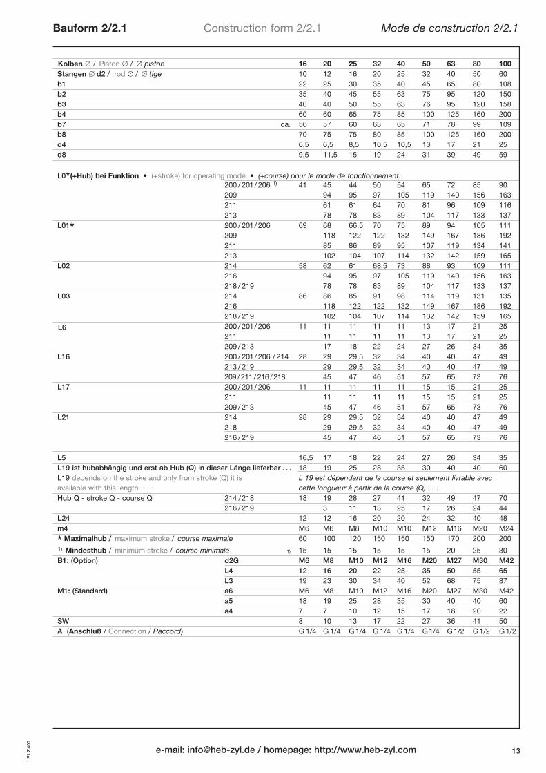
Kolben / Piston / piston 16 20 25 32 40 50 63 80 100Stangen d2 / rod / tige 10 12 16 20 25 32 40 50 60
b1 22 25 30 35 40 45 65 80 108
b2 35 40 45 55 63 75 95 120 150
b3 40 40 50 55 63 76 95 120 158
b4 60 60 65 75 85 100 125 160 200
b7 ca. 56 57 60 63 65 71 78 99 109
b8 70 75 75 80 85 100 125 160 200
d4 6,5 6,5 8,5 10,5 10,5 13 17 21 25
d8 9,5 11,5 15 19 24 31 39 49 59
L0*(+Hub) bei Funktion • (+stroke) for operating mode • (+course) pour le mode de fonctionnement:
200 / 201/ 206 1) 41 45 44 50 54 65 72 85 90
209 94 95 97 105 119 140 156 163
211 61 61 64 70 81 96 109 116
213 78 78 83 89 104 117 133 137
L01* 200 / 201/ 206 69 68 66,5 70 75 89 94 105 111
209 118 122 122 132 149 167 186 192
211 85 86 89 95 107 119 134 141
213 102 104 107 114 132 142 159 165
L02 214 58 62 61 68,5 73 88 93 109 111
216 94 95 97 105 119 140 156 163
218 / 219 78 78 83 89 104 117 133 137
L03 214 86 86 85 91 98 114 119 131 135
216 118 122 122 132 149 167 186 192
218 / 219 102 104 107 114 132 142 159 165
L6 200 / 201/ 206 11 11 11 11 11 13 17 21 25
211 11 11 11 11 13 17 21 25
209 / 213 17 18 22 24 27 26 34 35
L16 200 / 201/ 206 / 214 28 29 29,5 32 34 40 40 47 49
213 / 219 29 29,5 32 34 40 40 47 49
209 /211 /216 /218 45 47 46 51 57 65 73 76
L17 200 / 201/ 206 11 11 11 11 11 15 15 21 25
211 11 11 11 11 15 15 21 25
209 / 213 45 47 46 51 57 65 73 76
L21 214 28 29 29,5 32 34 40 40 47 49
218 29 29,5 32 34 40 40 47 49
216 / 219 45 47 46 51 57 65 73 76
L5 16,5 17 18 22 24 27 26 34 35
L19 ist hubabhängig und erst ab Hub (Q) in dieser Länge lieferbar . . . 18 19 25 28 35 30 40 40 60
L19 depends on the stroke and only from stroke (Q) it is L 19 est dépendant de la course et seulement livrable avec
available with this length . . . cette longueur à partir de la course (Q) . . .
Hub Q - stroke Q - course Q 214 /218 18 19 28 27 41 32 49 47 70
216 / 219 3 11 13 25 17 26 24 44
L24 12 12 16 20 20 24 32 40 48
m4 M6 M6 M8 M10 M10 M12 M16 M20 M24
* Maximalhub / maximum stroke / course maximale 60 100 120 150 150 150 170 200 200
1) Mindesthub / minimum stroke / course minimale 1) 15 15 15 15 15 15 20 25 30
B1: (Option) d2G M6 M8 M10 M12 M16 M20 M27 M30 M42
L4 12 16 20 22 25 35 50 55 65
L3 19 23 30 34 40 52 68 75 87
M1: (Standard) a6 M6 M8 M10 M12 M16 M20 M27 M30 M42
a5 18 19 25 28 35 30 40 40 60
a4 7 7 10 12 15 17 18 20 22
SW 8 10 13 17 22 27 36 41 50
A (Anschluß / Connection / Raccord) G 1/4 G 1/4 G1/4 G 1/4 G 1/4 G1/4 G1/2 G1/2 G1/2
Bauform 2/2.1 Construction form 2/2.1 Mode de construction 2/2.1
e-mail: [email protected] / homepage: http://www.heb-zyl.com 13
BLZ400

BLZ 400
Bauform 3/3.1 Construction form 3/3.1 Mode de construction 3/3.1
HEB Hydraulik-Elementebau GmbH / Tel. (0761) 130 99-0, Fax (0761) 13 50 6614
(3) (3.1) Bauform 3Construction form
Mode de construction
Bauform 3.1Construction form
Mode de construction
Zylinderseite - page ➀ . . .➃
M1
M1 M2
Senkung für DIN EN ISO 4762
Counterbore for . . .
noyure pour . . .
BLZ400
BLZ NI 400 DK
BLZ NI 400
BLZ 400 DK
Detaillierte Beschreibung der Schalter: Seite 6
Detailed description of the proximity sensors see page 6
Description des détecteurs de proximité intégrés voir page 6
Detaillierte Beschreibung der Schalter: Seite 6
Detailed description of the proximity sensors see page 6
Description des détecteurs de proximité intégrés voir page 6
wie BLZ 400,
mit durchgehender Kolbenstange
with through-going piston rod
avec tige de piston continu
wie BLZ NI 400,
mit durchgehender Kolbenstange
with through-going piston rod
avec tige de piston continu
mit integrierten Näherungsschaltern
with integrated proximity sensors
avec détecteurs de proximité intégrés
L4
L3
d2G
a4 + Hub / stroke / course
➀
➁
➂
➃
➀
➁
➂
➃
➀
➁
➂
➃
➀
➁
➂
➃

Bauform 3/3.1 Construction form 3/3.1 Mode de construction 3/3.1
e-mail: [email protected] / homepage: http://www.heb-zyl.com 15
Kolben / Piston / piston 16 20 25 32 40 50 63 80 100Stangen d2 / rod / tige 10 12 16 20 25 32 40 50 60
b1 22 25 30 35 40 45 65 80 108
b2 35 40 45 55 63 75 95 120 150
b3 40 40 50 55 63 76 95 120 158
b4 60 60 65 75 85 100 125 160 200
b7 ca. 56 57 60 63 65 71 78 99 109
b8 70 75 75 80 85 100 125 160 200
d4 6,5 6,5 8,5 10,5 10,5 13 17 21 25
d8 9,5 11,5 15 19 24 31 39 49 59
L0* (+Hub) bei Funktion • (+stroke) for operating mode • (+course) pour le mode de fonctionnement:
200 / 201/ 206 1) 41 45 44 50 54 65 72 85 90
209 94 95 97 105 119 140 156 163
211 61 61 64 70 81 96 109 116
213 78 78 83 89 104 117 133 137
L01* 200 / 201/ 206 69 68 66,5 70 75 89 94 105 111
209 118 122 122 132 149 167 186 192
211 85 86 89 95 107 119 134 141
213 102 104 107 114 132 142 159 165
L02 214 58 62 61 68,5 73 88 93 109 111
216 94 95 97 105 119 140 156 163
218 / 219 78 78 83 89 104 117 133 137
L03 214 86 86 85 91 98 114 119 131 135
216 118 122 122 132 149 167 186 192
218 / 219 102 104 107 114 132 142 159 165
L6 200 / 201/ 206 11 11 11 11 11 13 17 21 25
211 11 11 11 11 13 17 21 25
209 / 213 17 18 22 24 27 26 34 35
L16 200 / 201/ 206 / 214 28 29 29,5 32 34 40 40 47 49
213 / 219 29 29,5 32 34 40 40 47 49
209 /211 /216 /218 45 47 46 51 57 65 73 76
L17 200 / 201/ 206 11 11 11 11 11 15 15 21 25
211 11 11 11 11 15 15 21 25
209 / 213 45 47 46 51 57 65 73 76
L21 214 28 29 29,5 32 34 40 40 47 49
218
216 / 219 45 47 46 51 57 65 73 76
L5 16,5 17 18 22 24 27 26 34 35
L19 ist hubabhängig und erst ab Hub (Q) in dieser Länge lieferbar . . . 18 19 25 28 35 30 40 40 60
L19 depends on the stroke and only from stroke (Q) it is L 19 est dépendant de la course et seulement livrable avec
available with this length . . . cette longueur à partir de la course (Q) . . .
Hub Q - stroke Q - course Q
214 / 218 18 19 28 27 41 32 49 47 70
216 / 219 3 11 13 25 17 26 24 44
L24 12 12 16 20 20 24 32 40 48
m4 M6 M6 M8 M10 M10 M12 M16 M20 M24
* Maximalhub / maximum stroke / course maximale 60 100 120 150 150 150 170 200 200
1) Mindesthub / minimum stroke / course minimale 1) 15 15 15 15 15 15 20 25 30
B1: (Option) d2G M6 M8 M10 M12 M16 M20 M27 M30 M42
L4 12 16 20 22 25 35 50 55 65
L3 19 23 30 34 40 52 68 75 87
M1: (Standard) a6 M6 M8 M10 M12 M16 M20 M27 M30 M42
a5 18 19 25 28 35 30 40 40 60
a4 7 7 10 12 15 17 18 20 22
SW 8 10 13 17 22 27 36 41 50
A (Anschluß / Connection / Raccord) G 1/4 G 1/4 G1/4 G 1/4 G 1/4 G1/4 G1/2 G1/2 G1/2
BLZ400

Detaillierte Beschreibung der Schalter: Seite 6
Detailed description of the proximity sensors see page 6
Description des détecteurs de proximité intégrés voir page 6
BLZ 400
Bauform 4.1 Construction form 4.1 Mode de construction 4.1
HEB Hydraulik-Elementebau GmbH / Tel. (0761) 130 99-0, Fax (0761) 13 50 6616
X
Y
O-Ring - seal,
joint torique
O-Ring - seal,
joint torique
Einzelheit Z,
detail, détail
Einzelheit Z,
detail, détail
Zylinderseite - page ➀ . . .➃
M1
M1 M2
BLZ400
BLZ NI 400 DK
BLZ NI 400
BLZ 400 DK
Detaillierte Beschreibung der Schalter: Seite 6
Detailed description of the proximity sensors see page 6
Description des détecteurs de proximité intégrés voir page 6
wie BLZ 400,
mit durchgehender Kolbenstange
with through-going piston rod
avec tige de piston continu
wie BLZ NI 400,
mit durchgehender Kolbenstange
with through-going piston rod
avec tige de piston continu
mit integrierten Näherungsschaltern
with integrated proximity sensors
avec détecteurs de proximité intégrés
L4
L3
d2G
a4 + Hub / stroke / course
➀
➁
➂
➃
➀
➁
➂
➃
➀
➁
➂
➃
➀
➁
➂
➃

Kolben / Piston / piston 16 20 25 32 40 50 63 80 100Stangen d2 / rod / tige 10 12 16 20 25 32 40 50 60
b2 35 40 45 55 63 75 95 120 150
b4 60 60 65 75 85 100 125 160 200
b5 26 31 35 45 53 63 79 102 130
b7 ca. 56 57 60 63 65 71 78 99 109
b8 70 75 75 80 85 100 125 160 200
C1 10 10 10 10 10 13 16 16 20
C2 4 4 4 5 5 6 10 10 12
d6 5,2 5,2 5,2 6,5 6,5 6,5 8,5 10,5 10,5
d8 9,5 11,5 15 19 24 31 39 49 59
L0* (+Hub) bei Funktion • (+stroke) for operating mode • (+course) pour le mode de fonctionnement:
200 / 201/ 206 1) 41 45 44 50 54 65 72 85 90
209 94 95 97 105 119 140 156 163
211 61 61 64 70 81 96 109 116
213 78 78 83 89 104 117 133 137
L01* 200 / 201/ 206 69 68 66,5 70 75 89 94 105 111
209 118 122 122 132 149 167 186 192
211 85 86 89 95 107 119 134 141
213 102 104 107 114 132 142 159 165
L02 214 1) 58 62 61 68,5 73 88 93 109 111
216 94 95 97 105 119 140 156 163
218 / 219 78 78 83 89 104 117 133 137
L03 214 86 86 85 91 98 114 119 131 135
216 118 122 122 132 149 167 186 192
218 / 219 102 104 107 114 132 142 159 165
L9 200 / 201/ 206 7 7 7 8 8 10 13 17 22
211 7 7 8 8 10 13 17 22
209 / 213 17 18 22 24 27 26 34 35
L10 200 / 201/ 206 / 214 25 28 29 30 33 41 41 49 46
213 / 219 28 29 30 33 41 41 49 46
209 / 211 / 216 / 218 31 32 33 39 41 47 60 60
L11 200 / 201/ 206 19 13 15 11 11 13 17 21 25
211 13 15 11 11 13 17 21 25
209/213 31 32 33 39 41 47 60 60
L16 200 / 201/ 206/214 28 29 29,5 32 34 40 40 47 49
213 / 219 29 29,5 32 34 40 40 47 49
209 /211 /216 /218 45 47 46 51 57 65 73 76
L17 200 / 201/ 206 11 11 11 11 11 15 15 21 25
211 11 11 11 11 15 15 21 25
209 / 213 45 47 46 51 57 65 73 76
L21 214 28 29 29,5 32 34 40 40 47 49
218 29 29,5 32 34 40 40 47 49
216 / 219 45 47 46 51 57 65 73 76
L26 214 25 28 29 30 33 41 41 49 46
218 28 29 30 33 41 41 49 46
216/219 31 32 33 39 41 47 60 60
L5 16,5 17 18 22 24 27 26 34 35
L19 ist hubabhängig und erst ab Hub (Q) in dieser Länge lieferbar 18 19 25 28 35 30 40 40 60
L19 depends on the stroke and only from stroke (Q) it is L 19 est dépendant de la course et seulement livrable avec
available with this length . . . cette longueur à partir de la course (Q) . . .
Hub Q - stroke Q - course Q 214/218 18 19 28 27 41 32 49 47 70
216/219 3 11 13 25 17 26 24 44
* Maximalhub / maximum stroke / course maximale 60 100 120 150 150 150 170 200 200
1) Mindesthub / minimum stroke / course minimale 1) 15 15 15 15 15 15 20 25 30
B1: (Option) d2G M6 M8 M10 M12 M16 M20 M27 M30 M42
L4 12 16 20 22 25 35 50 55 65
L3 19 23 30 34 40 52 68 75 87
M1: (Standard) a6 M6 M8 M10 M12 M16 M20 M27 M30 M42
a5 18 19 25 28 35 30 40 40 60
a4 7 7 10 12 15 17 18 20 22
SW 8 10 13 17 22 27 36 41 50
O-Ring - seal, joint torique 7x1,5 7x1,5 7x1,5 7x1,5 7x1,5 10x1,5 13x1,5 13x1,5 17x1,5
Bauform 4.1 Construction form 4.1 Mode de construction 4.1
e-mail: [email protected] / homepage: http://www.heb-zyl.com 17
BLZ400

BLZ 400
Bauform 5.1 Construction form 5.1 Mode de construction 5.1
HEB Hydraulik-Elementebau GmbH / Tel. (0761) 130 99-0, Fax (0761) 13 50 6618
X
Y
O-Ring - seal,
joint torique
O-Ring - seal,
joint torique
Einzelheit Z, detail, détail
Einzelheit Z,
detail, détail
Zylinderseite - page ➀ . . .➃
M1
M1M2
BLZ400
BLZ NI 400 DK
BLZ NI 400
BLZ 400 DK
Detaillierte Beschreibung der Schalter: Seite 6
Detailed description of the proximity sensors see page 6
Description des détecteurs de proximité intégrés voir page 6
Detaillierte Beschreibung der Schalter: Seite 6
Detailed description of the proximity sensors see page 6
Description des détecteurs de proximité intégrés voir page 6
wie BLZ 400,
mit durchgehender Kolbenstange
with through-going piston rod
avec tige de piston continu
wie BLZ NI 400,
mit durchgehender Kolbenstange
with through-going piston rod
avec tige de piston continu
mit integrierten Näherungsschaltern
with integrated proximity sensors
avec détecteurs de proximité intégrés
L4
L3
d2G
a4 + Hub / stroke / course
➀
➁
➂
➃
➀
➁
➂
➃
➀
➁
➂
➃
➀
➁
➂
➃

Bauform 5.1 Construction form 5.1 Mode de construction 5.1
e-mail: [email protected] / homepage: http://www.heb-zyl.com 19
Kolben / Piston / piston 16 20 25 32 40 50 63 80 100Stangen d2 / rod / tige 10 12 16 20 25 32 40 50 60
b2 35 40 45 55 63 75 95 120 150
b4 60 60 65 75 85 100 125 160 200
b6 20 26 31 41 49 59 75 100 130
b7 ca. 56 57 60 63 65 71 78 99 109
b8 70 75 75 80 85 100 125 160 200
C1 10 10 10 10 10 13 16 16 20
C2 4 4 4 5 5 6 10 10 12
d1 M6 M8 M10 M12 M16 M20 M27 M30 M42
d7 M8 M8 M8 M8 M8 M8 M12 M12 M12
d8 9,5 11,5 15 19 24 31 39 49 59
L0* (+Hub) bei Funktion • (+stroke) for operating mode • (+course) pour le mode de fonctionnement:
200 / 201/ 206 1) 41 45 44 50 54 65 72 85 90
209 94 95 97 105 119 140 156 163
211 61 61 64 70 81 96 109 116
213 78 78 83 89 104 117 133 137
L01* 200 / 201/ 206 69 68 66,5 70 75 89 94 105 111
209 118 122 122 132 149 167 186 192
211 85 86 89 95 107 119 134 141
213 102 104 107 114 132 142 159 165
L02 214 2) 58 62 61 68,5 73 88 93 109 111
216 94 95 97 105 119 140 156 163
218 / 219 78 78 83 89 104 117 133 137
L03 214 86 86 85 91 98 114 119 131 135
216 118 122 122 132 149 167 186 192
218 / 219 102 104 107 114 132 142 159 165
L9 200 / 201/ 206 7 7 7 8 8 10 13 17 22
211 7 7 8 8 10 13 17 22
209 / 213 17 18 22 24 27 26 34 35
L13 200 / 201/ 206 23 20 13 11 11 13 17 21 25
211 20 13 11 11 13 17 21 25
209 / 213 29 20 22 24 27 26 34 35
L16 200 / 201/ 206/214 28 29 29,5 32 34 40 40 47 49
213 / 219 29 29,5 32 34 40 40 47 49
209 /211 /216 /218 45 47 46 51 57 65 73 76
L17 200 / 201/ 206 11 11 11 11 11 15 15 21 25
211 11 11 11 11 15 15 21 25
209 / 213 45 47 46 51 57 65 73 76
L21 214 28 29 29,5 32 34 40 40 47 49
218 29 29,5 32 34 40 40 47 49
216 / 219 45 47 46 51 57 65 73 76
L3 18 19 25 28 35 30 40 40 60
L5 16,5 17 18 22 24 27 26 34 35
L12 28,5 29 20 22 24 27 26 34 35
L14 16 15 16 16 18 18 22 22 22
L15 7 7 10 12 15 17 18 20 22
L19 ist hubabhängig und erst ab Hub (Q) in dieser Länge lieferbar 18 19 25 28 35 30 40 40 60
L19 depends on the stroke and only from stroke (Q) it is L 19 est dépendant de la course et seulement livrable avec
available with this length . . . cette longueur à partir de la course (Q) . . .
Hub Q - stroke Q - course Q 214/218 18 19 28 27 41 32 49 47 70
216/219 3 11 13 25 17 26 24 44
* Maximalhub / maximum stroke / course maximale 60 100 120 150 150 150 170 200 200
1) 2) Mindesthub / minimum stroke / course minimale 1) 35 30 20 15 15 15 20 25 30
2) 25 20 10 0 0 0 0 0 0
B1: (Option) d2G M6 M8 M10 M12 M16 M20 M27 M30 M42
L4 12 16 20 22 25 35 50 55 65
L3 19 23 30 34 40 52 68 75 87
M1: (Standard) a6 M6 M8 M10 M12 M16 M20 M27 M30 M42
a5 18 19 25 28 35 30 40 40 60
a4 7 7 10 12 15 17 18 20 22
SW 8 10 13 17 22 27 36 41 50
O-Ring - seal, joint torique 7x1,5 7x1,5 7x1,5 7x1,5 7x1,5 10x1,5 13x1,5 13x1,5 17x1,5
BLZ400

• spiegelbildlich zu Bauform 6 -> 6.4 (mit Nut Zusatz: N4)mirror image to construction form 6 -> 6.4 (with groove: N4)
renversé du mode de construction 6 -> 6.4 (avec rainure: N4)
• spiegelbildlich zu Bauform 6.1 -> 6.14 (mit Nut Zusatz: N4)mirror image to construction form 6 -> 6.14 (with groove: N4)
renversé du mode de construction 6 -> 6.14 (avec rainure: N4)
Bestellbeispiel / Example of order / Exemple de commande:
BLZ400-6.4-32/20/15-206/M1/N4BLZNI400-6.4-32/20/15-206/M1/N4
BLZ 400
Bauform 6/6.1 Construction form 6/6.1 Mode de construction 6/6.1
HEB Hydraulik-Elementebau GmbH / Tel. (0761) 130 99-0, Fax (0761) 13 50 6620
Bauform 6Construction form
Mode de construction
Bauform 6.1Construction form
Mode de construction
Einzelheit Z, detail, détail
O-Ring - seal,
joint torique
Einzelheit Z, detail, détail
O-Ring - seal, joint torique
Zylinderseite - page ➀ . . .➃
M1
M1 M2
BLZ400
BLZ NI 400 DK
BLZ NI 400
BLZ 400 DK
Detaillierte Beschreibung der Schalter: Seite 6
Detailed description of the proximity sensors see page 6
Description des détecteurs de proximité intégrés voir page 6
Detaillierte Beschreibung der Schalter: Seite 6
Detailed description of the proximity sensors see page 6
Description des détecteurs de proximité intégrés voir page 6
wie BLZ 400,
mit durchgehender Kolbenstange
with through-going piston rod
avec tige de piston continu
wie BLZ NI 400,
mit durchgehender Kolbenstange
with through-going piston rod
avec tige de piston continu
mit integrierten Näherungsschaltern
with integrated proximity sensors
avec détecteurs de proximité intégrés
Bauform 6.4Construction form
Mode de construction
Bauform 6.14Construction form
Mode de construction
spiegelbildliche Bauform s.o.mirror image to construction form see above
renversé du mode de construction c.f.
L4
L3
d2G
a4 + Hub / stroke / course
➀
➁
➂
➃
➀
➁
➂
➃
➀
➁
➂
➃
➀
➁
➂
➃
➀
➁
➂
➃

Bauform 6/6.1 Construction form 6/6.1 Mode de construction 6/6.1
e-mail: [email protected] / homepage: http://www.heb-zyl.com 21
Kolben / Piston / piston 16 20 25 32 40 50 63 80 100Stangen d2 / rod / tige 10 12 16 20 25 32 40 50 60
b2 35 40 45 55 63 75 95 120 150
b3 40 40 50 55 63 76 95 120 158
b4 60 60 65 75 85 100 125 160 200
b7 ca. 56 57 60 63 65 71 78 99 109
b8 70 75 75 80 85 100 125 160 200
C1 10 10 10 10 10 13 16 16 20
C2 4 4 4 5 5 6 10 10 12
d1 M6 M8 M10 M12 M16 M20 M27 M30 M42
d8 9,5 11,5 15 19 24 31 39 49 59
d9 6,5 6,5 6,5 8,5 8,5 8,5 10,5 13 13
L0* (+Hub) bei Funktion • (+stroke) for operating mode • (+course) pour le mode de fonctionnement:
200 / 201/ 206 1) 41 45 44 50 54 65 72 85 90
209 94 95 97 105 119 140 156 163
211 61 61 64 70 81 96 109 116
213 78 78 83 89 104 117 133 137
L01* 200 / 201/ 206 2) 69 68 66,5 70 75 89 94 105 111
209 118 122 122 132 149 167 186 192
211 85 86 89 95 107 119 134 141
213 102 104 107 114 132 142 159 165
L02 214 58 62 61 68,5 73 88 93 109 111
216 94 95 97 105 119 140 156 163
218 / 219 78 78 83 89 104 117 133 137
L03 214 86 86 85 91 98 114 119 131 135
216 118 122 122 132 149 167 186 192
218 / 219 102 104 107 114 132 142 159 165
L9 / L29 200 / 201/ 206 7 7 7 8 8 10 13 17 22
211 7 7 8 8 10 13 17 22
209 / 213 17 18 22 24 27 26 34 35
L16 200 / 201/ 206 / 214 28 29 29,5 32 34 40 40 47 49
213 / 219 29 29,5 32 34 40 40 47 49
209 / 211 / 216 / 218 45 47 46 51 57 65 73 76
L17 200 / 201/ 206 11 11 11 11 11 15 15 21 25
211 11 11 11 11 15 15 21 25
209/213 45 47 46 51 57 65 73 76
L21 214 28 29 29,5 32 34 40 40 47 49
218 29 29,5 32 34 40 40 47 49
216 / 219 45 47 46 51 57 65 73 76
L3 18 19 25 28 35 30 40 40 60
L5 / L28 16,5 17 18 22 24 27 26 34 35
L15 7 7 10 12 15 17 18 20 22
L19 ist hubabhängig und erst ab Hub (Q) in dieser Länge lieferbar . . . 18 19 25 28 35 30 40 40 60
L19 depends on the stroke and only from stroke (Q) it is L 19 est dépendant de la course et seulement livrable avec
available with this length . . . cette longueur à partir de la course (Q) . . .
Hub Q - stroke Q - course Q
214 / 218 18 19 28 27 41 32 49 47 70
216/219 3 11 13 25 17 26 24 44
L22 200 / 201/ 206 25 26 26 27 28 32 33 41 45
211 26 26 27 28 32 33 41 45
209 / 213 17 18 22 24 27 26 34 35
L25 16,5 17 18 18 20 27 26 34 35
L27 12 12 12 16 16 16 20 24 24
m9 M6 M6 M6 M8 M8 M8 M10 M12 M12
* Maximalhub / maximum stroke / course maximale 60 100 120 150 150 150 170 200 200
1) 2) Mindesthub / minimum stroke / course minimale 1) 15 15 15 15 15 15 20 25 30
2) 0 5 8 10 0 0 0 5 5
B1: (Option) d2G M6 M8 M10 M12 M16 M20 M27 M30 M42
L4 12 16 20 22 25 35 50 55 65
L3 19 23 30 34 40 52 68 75 87
M1: (Standard) a6 M6 M8 M10 M12 M16 M20 M27 M30 M42
a5 18 19 25 28 35 30 40 40 60
a4 7 7 10 12 15 17 18 20 22
SW 8 10 13 17 22 27 36 41 50
O- Ring - seal, joint torique 7x1,5 7x1,5 7x1,5 7x1,5 7x1,5 10x1,5 13x1,5 13x1,5 17x1,5
BLZ400

BLZ 400
Bauform 7/7.1 Construction form 7/7.1 Mode de construction 7/7.1
HEB Hydraulik-Elementebau GmbH / Tel. (0761) 130 99-0, Fax (0761) 13 50 6622
Bauform 7Construction form
Mode de construction
O-Ring - seal,
joint torique
O-Ring - seal,
joint torique
Bauform 7.1Construction form
Mode de construction
A
A
(7)
Einzelheit Z, detail, détail
Einzelheit Z, detail, détail
(7.1)
B
B
Senkung für
DIN EN ISO 4762
Counterbore for . . .
noyure pour . . .
Zylinderseite - page ➀ . . .➃
M1
M1 M2
BLZ400
BLZ NI 400 DK
BLZ NI 400
BLZ 400 DK
Detaillierte Beschreibung der Schalter: Seite 6
Detailed description of the proximity sensors see page 6
Description des détecteurs de proximité intégrés voir page 6
Detaillierte Beschreibung der Schalter: Seite 6
Detailed description of the proximity sensors see page 6
Description des détecteurs de proximité intégrés voir page 6
wie BLZ 400,
mit durchgehender Kolbenstange
with through-going piston rod
avec tige de piston continu
wie BLZ NI 400,
mit durchgehender Kolbenstange
with through-going piston rod
avec tige de piston continu
mit integrierten Näherungsschaltern
with integrated proximity sensors
avec détecteurs de proximité intégrés
L4
L3
d2G
a4 + Hub / stroke / course
➀
➁
➂
➃
➀
➁
➂
➃
➀
➁
➂
➃
➀
➁
➂
➃

Bauform 7/7.1 Construction form 7/7.1 Mode de construction 7/7.1
e-mail: [email protected] / homepage: http://www.heb-zyl.com 23
Kolben / Piston / piston 16 20 25 32 40 50 63 80 100Stangen d2 / rod / tige 10 12 16 20 25 32 40 50 60
b1 22 25 30 35 40 45 65 80 108
b2 35 40 45 55 63 75 95 120 150
b3 40 40 50 55 63 76 95 120 158
b4 60 60 65 75 85 100 125 160 200
b7 ca. 56 57 60 63 65 71 78 99 109
b8 70 75 75 80 85 100 125 160 200
C3 10 10 10 10 10 10 13 13 16
C4 4 4 4 5 5 5 8 8 10
d1 M6 M8 M10 M12 M16 M20 M27 M30 M42
d4 6,5 6,5 8,5 10,5 10,5 13 17 21 25
d8 9,5 11,5 15 19 24 31 39 49 59
e1 46 46 52 60 68 80 105 120 158
L0* (+Hub) bei Funktion • (+stroke) for operating mode • (+course) pour le mode de fonctionnement:
200 / 201/ 206 1) 41 45 44 50 54 65 72 85 90
209 94 95 97 105 119 140 156 163
211 61 61 64 70 81 96 109 116
213 78 78 83 89 104 117 133 137
L01* 200 / 201/ 206 69 68 66,5 70 75 89 94 105 111
209 118 122 122 132 149 167 186 192
211 85 86 89 95 107 119 134 141
213 102 104 107 114 132 142 159 165
L02 214 58 62 61 68,5 73 88 93 109 111
216 94 95 97 105 119 140 156 163
218 / 219 78 78 83 89 104 117 133 137
L03 214 86 86 85 91 98 114 119 131 135
216 118 122 122 132 149 167 186 192
218 / 219 102 104 107 114 132 142 159 165
L16 200 / 201/ 206 / 214 28 29 29,5 32 34 40 40 47 49
213 / 219 29 29,5 32 34 40 40 47 49
209 / 211 / 216 / 218 45 47 46 51 57 65 73 76
L17 200 / 201/ 206 11 11 11 11 11 15 15 21 25
211 11 11 11 11 15 15 21 25
209/213 45 47 46 51 57 65 73 76
L21 214 28 29 29,5 32 34 40 40 47 49
218 29 29,5 32 34 40 40 47 49
216 / 219 45 47 46 51 57 65 73 76
L3 18 19 25 28 35 30 40 40 60
L15 7 7 10 12 15 17 18 20 22
L19 ist hubabhängig und erst ab Hub (Q) in dieser Länge lieferbar . . .18 19 25 28 35 30 40 40 60
L19 depends on the stroke and only from stroke (Q) it is L 19 est dépendant de la course et seulement livrable avec
available with this length . . . cette longueur à partir de la course (Q) . . .
Hub Q - stroke Q - course Q 214/218 18 19 28 27 41 32 49 47 70
216/219 3 11 13 25 17 26 24 44
L24 12 12 16 20 20 24 32 40 48
m4 M6 M6 M8 M10 M10 M12 M16 M20 M24
* Maximalhub / maximum stroke / course maximale 60 100 120 150 150 150 170 200 200
1) Mindesthub / minimum stroke / course minimale 1)15 15 15 15 15 15 20 25 30
B1: (Option) d2G M6 M8 M10 M12 M16 M20 M27 M30 M42
L4 12 16 20 22 25 35 50 55 65
L3 19 23 30 34 40 52 68 75 87
M1: (Standard) a6 M6 M8 M10 M12 M16 M20 M27 M30 M42
a5 18 19 25 28 35 30 40 40 60
a4 7 7 10 12 15 17 18 20 22
SW 8 10 13 17 22 27 36 41 50
O- Ring - seal, joint torique 7x1,5 7x1,5 7x1,5 7x1,5 7x1,5 7x1,5 10x1,5 10x1,5 13x1,5
BLZ400

BLZ 400
Bauform 8/8.1 Construction form 8/8.1 Mode de construction 8/8.1
HEB Hydraulik-Elementebau GmbH / Tel. (0761) 130 99-0, Fax (0761) 13 50 6624
BLZ NI 400
BLZ 400 DKsiehe Bauform 7/7.1 see construction form 7/7.1 voir mode deconstruction 7/7.1Seite 20/21 page 20/21 page 20/21
(8)
(8.1)
B
A
O-Ring - seal,
joint torique
Bauform 8Construction form
Mode de construction
Bauform 8.1Construction form
Mode de construction
X
X X
X
BLZ NI 400 DKsiehe Bauform 7/7.1 see construction form 7/7.1 voir mode deconstruction 7/7.1Seite 20/21 page 20/21 page 20/21
Einzelheit Z, detail, détail Zylinderseite - page ➀ . . .➃
M1
Senkung für DIN EN ISO 4762
Counterbore for . . .
noyure pour . . .
BLZ400
Detaillierte Beschreibung der Schalter: Seite 6
Detailed description of the proximity sensors see page 6
Description des détecteurs de proximité intégrés voir page 6
Detaillierte Beschreibung der Schalter: Seite 24 + 25
Detailed description of the proximity sensors see page 24 + 25
Description des détecteurs de proximité intégrés voir page 24 + 25
wie BLZ 400,
mit durchgehender Kolbenstange
with through-going piston rod
avec tige de piston continu
wie BLZ NI 400,
mit durchgehender Kolbenstange
with through-going piston rod
avec tige de piston continu
L4
L3
d2G
➀
➁
➂
➃
➀
➁
➂
➃
mit integrierten Näherungsschaltern
with integrated proximity sensors
avec détecteurs de proximité intégrés

Kolben / Piston / piston 16 20 25 32 40 50 63 80 100Stangen d2 / rod / tige 10 12 16 20 25 32 40 50 60
b1 22 25 30 35 40 45 65 80 108
b2 35 40 45 55 63 75 95 120 150
b3 40 40 50 55 63 76 95 120 158
b4 60 60 65 75 85 100 125 160 200
b7 ca. 56 57 60 63 65 71 78 99 109
b8 70 75 75 80 85 100 125 160 200
C3 10 10 10 10 10 10 13 13 16
C4 4 4 4 5 5 5 8 8 10
d1 M6 M8 M10 M12 M16 M20 M27 M30 M42
d4 6,5 6,5 8,5 10,5 10,5 13 17 21 25
d8 9,5 11,5 15 19 24 31 39 49 59
e2 23 23 26 30 34 40 52,5 60 79
L0* (+Hub) bei Funktion • (+stroke) for operating mode • (+course) pour le mode de fonctionnement:
200 / 201/ 206 1) 41 45 44 50 54 65 72 85 90
209 94 95 97 105 119 140 156 163
211 61 61 64 70 81 96 109 116
213 78 78 83 89 104 117 133 137
L01* 200 / 201/ 206 69 68 66,5 70 75 89 94 105 111
209 118 122 122 132 149 167 186 192
211 85 86 89 95 107 119 134 141
213 102 104 107 114 132 142 159 165
L16 200 / 201/ 206 28 29 29,5 32 34 40 40 47 49
213 29 29,5 32 34 40 40 47 49
209 / 211 45 47 46 51 57 65 73 76
L17 200 / 201/ 206 11 11 11 11 11 15 15 21 25
211 11 11 11 11 15 15 21 25
209/213 45 47 46 51 57 65 73 76
L3 18 19 25 28 35 30 40 40 60
L15 7 7 10 12 15 17 18 20 22
L24 12 12 16 20 20 24 32 40 48
m4 M6 M6 M8 M10 M10 M12 M16 M20 M24
Hub Q - stroke Q - course Q 60 100 120 150 150 150 170 200 200
* Maximalhub / maximum stroke / course maximale 60 100 120 150 150 150 170 200 200
1) Mindesthub / minimum stroke / course minimale 1) 15 15 15 15 15 15 20 25 30
B1: (Option) d2G M6 M8 M10 M12 M16 M20 M27 M30 M42
L4 12 16 20 22 25 35 50 55 65
L3 19 23 30 34 40 52 68 75 87
M1: (Standard) a6 M6 M8 M10 M12 M16 M20 M27 M30 M42
a5 18 19 25 28 35 30 40 40 60
a4 7 7 10 12 15 17 18 20 22
SW 8 10 13 17 22 27 36 41 50
O- Ring - seal, joint torique 7x1,5 7x1,5 7x1,5 7x1,5 7x1,5 7x1,5 10x1,5 10x1,5 13x1,5
Bauform 8/8.1 Construction form 8/8.1 Mode de construction 8/8.1
e-mail: [email protected] / homepage: http://www.heb-zyl.com 25
BLZ400

HEB Hydraulik-Elementebau GmbH / Tel. (0761) 1 30 99-0, Fax (0761) 13 50 66
Achtung - Typenbezeichnung bzw. Ident.Nr. sowie Kom.Nr. bei Ersatzbeschaffungund Ersatzteilbezug unbedingt angeben.
Attention - In case of order and purchase of spare parts it is absolutely necessary to indicate
the order specification or the number of identification as well as the commission number.
Attention - En cas d’acquisition des éléments de rechange indiquer absolutement la référence
de commande ou bien le numéro d’identification ainsi que le numéro de commission.
Sämtliche Zylinder unserer Fertigung sind mit genauer Typenbezeichnung bzw. Ident.-Nr. und der Kom.-Nr., die zusätzlich eingraviertwird, gekennzeichnet. Eine absolut einwandfreie Identifizierung bei Ersatzteilbeschaffung und Ersatzteilbezug ist hierdurch gewährleistet.
All cylinders of our production are provided with the exact order specification respectively the number of identification and the commission num-
ber which is additionally stamped on the cylinder. By this an absolutely perfect identification in case of order and purchase of spare parts is
guaranteed.
Tous les cylindres de notre production sont marqués avec la référence de commande exacte ou bien le numéro d’identification et le numéro
de commission qui est estampé additionnellement. Une identification absolument correcte pour l’acquisition des éléments de rechange est
garantie par cela.
Änderungen vorbehalten.Subject to change without notice.
Modification resérvée.
26
Bestellbeispiel Example of order Exemple de commande
HEB-Blockzylinderfür Betriebsdruck bis 400 bar, mit einge-bauten Näherungsschaltern1 = 2 QuerbohrungenKolben Ø 50mm, Kolbenstangen Ø 32mm,Hub 25,00mm206 = doppeltwirkendM1 = Kolbenstangenende mit InnengewindeN2 = Nut (Seite 2)S4 = WinkelsteckverbinderSPB2 = Schaltpunkt beidseitig 2mm vor Endlage
HEB bloc cylinder
for operating pressure up to 400bar,
with integrated proximity sensors
1 = 2 cross borings
piston Ø 50mm, piston-rod Ø 32mm,
stroke 25,00mm
206 = double-acting
M1 = piston-rod end with
internal thread
N2 = groove (page 2)
S4 = angular plug
SPB2 = sensing point both-sides
2mm before stroke end
HEB vérin bloc
pour pression de fonctionnement jusqu’á
400 bar, avec des détecteurs de proximité
1 = 2 forures transversales
Ø piston 50mm, Ø tige de piston 32mm,
course 25,00 mm
206 = à effet double
M1 = fin de la tige de piston avec
filet intérieur
N2 = rainure (page 2)
S4 = connecteur coudé
SPB2 =point de commutation des deux
côtés 2mm devant la fin de course
BLZNI400 - 1 - 50 / 32 / 25,00 - 206 / M1 / N2 / S4 / SPB2
Anhand der lieferbaren Befesti-gungs- und Funktionsarten kann dergewün-schte Zylindertyp gemäß fol-gendem Schlüssel festgelegt werden:
Au moyen des modes de fixation et
de fonctionnement livrables le type de
cylindre désiré selon la clé suivante:
By means of the deliverable fixation
systems and modes of operation the
desired cylinder type can be fixed accor-
ding to the following code:
Block-Zylinder / Block cylinder / Vérin bloc
Typenschlüssel Code Clé des types
BLZ400BLZNI400
BLZ400
BLZNI400 1 50 32 25,00 206 M1 N2 S4 SPB2 Zylindertyp und BetriebsdruckCylinder type and operating pressure
Type de vérin et pression de fonctionnement
Bauformen • Construction forms • Modes de construction
Kolben Ø mm • Piston Ø mm • Ø piston mm
Kolbenstangen Ø mm • Piston-rod Ø mm • Ø Tige de piston mm
Hub • Stroke • Course
Funktionsart • Mode of operation • Mode de fonctionnement
Kolbenstangenende • Piston-rod end • Fin de la tige de piston
Nut • Groove • Rainure
Sonderausstattungen • Special equipments • Equipements spéciaux
Schaltpunktverlagerung siehe Beschreibung Seite 2 Displacement of the sensing point see description page 2
Déplacement du point de commutation voir page 2

Blockzylinder
Nenndruck: 400 barPrüfdruck: 600 barMax. Hub: 200 mmKolben Ø: 125 bis 200 mmEinsatzgebiet:• Vorrichtungsbau• Entgrattechnik• PressenbauEndlagenabfrage: als BLZNI401
Block cylinder
Nominal pressure: 400 bar
Test pressure: 600 bar
Max. stroke: 200 mm
Piston Ø: 125 to 200 mm
Application area:
• Fixture
• Deburring
• Molding press
Sensing of end position: as BLZNI401
Vérin bloc
Pression nominale: 400 barPression de contrôle: 600 barMax. Course: 200 mmPiston Ø: 125 à 200 mm
Domain d’utilisation: • Construction de fixations• Technique d’ébavurage• Construction de pressesDétection de fin de course: en BLZNI401
Hydraulik-BlockzylinderBlock cylindersVérins blocs
BLZ401-11-2010
BLZ401BLZNI401
HEB Hydraulik-Elementebau GmbH
[email protected], www.heb-zyl.com

HEB Hydraulik-Elementebau GmbH / Tel. (0761) 130 99-0, Fax (0761) 13 50 662
Allgemeine Beschreibungund Hinweise
Blockbauweise, extrem kleineBaulängen, vorzugsweise fürkurze Hübe geeignet.
Bauformen gemäß Übersicht Seite 3.
lieferbare Funktionsarten 200 bis219 gemäß Übersicht Prospekt BLZ 400 / BLZNi 400.
Hübe nach Kundenwunsch, max.Hübe siehe Seite 3. Hubtoleranznach DIN/ISO 2768m.
Hubbegrenzung durch vordereund hintere Anschlagfläche, beiKolbengeschwindigkeiten über0,1 m/sec. ist mechanische Hub-begrenzung oder Endlagendämp-fung zu empfehlen.
Die eingebauten Dichtungen sindfür Hydroflüssigkeiten H, HL, HLPnach DIN 51524/51525 und denTemperaturbereich von -20° C bis+90° C geeignet. Bei höherenTem peraturen und anderen Druck -medien können entsprechendeDichtungswerkstoffe eingesetztwerden. (Absprache erforderlich).
Betriebsdruck – Nenndruck max.400 bar.
Kolben Ø 125, 140 und 160 mm.
Kolbenstangenlauffläche hartver-chromt, geschliffen und poliert,serienmäßige Ausrüstung mitStaubabstreifer, Stangenende mitInnengewinde.
Kolbenstangendichtung –PU-Nutring.
Kolbendichtung – PTFE – Gleitring(statisch nicht dicht).
Einzelheiten zu möglichen Funkti-onsarten und technischen Datender NI – Ausführung entnehmenSie bitte dem Prospekt BLZ 400 /BLZ-Ni 400.
General description and
informations
Bloc by bloc extremely small construc-
tion lengths, preferably appropriate to
short strokes.
Construction forms according to the
summary page 3.
Deliverable modes of operation
200 - 219. Please see the separate
brochure BLZ 400 / BLZNI 400.
Strokes according to the wishes of the
customers, max. strokes see page 3.
Stroke tolerance according to German
Standard DIN/ISO 2768m.
Stroke limitation through the front and
back stop face, for piston speeds
exceeding 0,1 m/sec we recommend a
mechanical stroke limitation or a
cushioning.
The installed seals are suitable to
hydraulic fluids H, HL, HLP according
to German Standard DIN 51524/
51525 and to temperatures from -20°C
to +90° C. With higher temperatures
and other pressure mediums appro-
priate sealing material can be used.
(Arrangement necessary).
Operating pressure – nominal pressure
maxim. 400 bar.
Piston Ø 125, 140 and 160 mm.
Piston-rods hard-chrome plated,
ground and polished, standard equi-
pement with dust scraper, piston-rod
end with internal thread.
Piston-rod seal – PU/groove ring.
Piston seal – PTFE – axial face seal
(no static sealing effect).
Description of the modes of operation
and the special equipments of the
Ni - version, please see the separate
brochure BLZ 400 / BLZ-NI 400.
Description générale et desinformations
Bloc à bloc des mesures de construc-tion extrêmement petites, de préféren-ce appropriées aux courses courtes.
Modes de construction selon l’aperçupage 3.
Modes de fonctionnement livrables 200 - 219. Veuillez tenir compte du pro-spectus spécial BLZ 400 / BlzNI 400.
Courses selon le désir du client, descourses max. voir page 3. Tolérancede course selon DIN/ISO 2768m.
Limitation de course par surface d’arrêtde devant et de derrière, pour desvitesses de piston plus de 0,1 m/sec.nous recommandons une limitation decourse mécanique ou amortissementde la fin de course.
Les garnitures installées sont appro-priées pour des liquides hydrauliquesH, HL, HLP selon DIN 51524/51525 etpour des températures de -20° C a+90° C. Pour des températuressupérieures et d’autres médias depression on peut utiliser des matièresde garniture conformes. (Accordnécessaire).
Pression de fonctionnement – pressionnominale maxim. 400 bar.
Ø piston 125, 140 et 160 mm.
Tiges de piston chromées durement,meulées et polies, équipement stan-dard avec dépoussiéreur, fin de la tigede piston avec filet intérieur.
Garniture de la tige de piston –PU/ joint en U à lèvres.
Garniture de piston – PTFE – anneaude glissement (sans effet hermétique).
Decription des modes de fonctionne-ment et équipements speciaux du ver-sion NI, veuillez tenir compte du pros-pectus spécial BLZ 400 / Blz-NI 400.
•
•
•
•
•
•
•
•
•
•
•
•
BLZ401

Übersicht der lieferbaren Summary of the deliverable Aperçu sur les modes de Bauformen construction forms construction livrables
BezeichnungOrder specification
Référence decommande
BeschreibungDescription
Description
e-mail: [email protected] / homepage: http://www.heb-zyl.com 3
BLZ401
125 140 160
80 90 100
122,7 153,9 201
72,5 90,3 122,5
12270 15390 20100
24540 30780 40200
36810 46180 60310
49080 61560 80400
7250 9030 12250
14500 18060 24500
21730 27090 36750
29000 36120 49000
Technische Daten • Technical data • Caractéristiques techniques
Kolben Ø mm • Piston Ø mm • Ø piston mm
Kolbenstangen Ø mm • Piston-rod Ø mm • Ø tige de piston mm
Kolbenfläche (stoßend) (AK) cm2
piston face (pushing) • de piston (poussante)
Kolbenringfläche (ziehend) (AR) cm2
Piston ring face (drawing action) • Surface du segment de piston (tirant)
Kraft (AK) daN • Force • Force
Kraft (AR) daN • Force • Force
100 bar
200 bar
300 bar
400 bar
100 bar
200 bar
300 bar
400 bar
125 140 160
200 180 170
90 75 75
170 150 140
120 100 100
170 165 155
60 50 45
140 130 125
90 85 75
155 140 125
90 75 70
125 105 90
125 115 105
60 50 40
90 85 75
Maximale Hublänge • Maximum strokes • Courses maximales
Funktionsarten • modes of operation • modes de fontionnement
Kolben Ø mm • Piston Ø mm • Ø piston mm
BLZ 401
BLZ NI 401
BLZ 401 DK
BLZ NI 401 DK
200 / 201 / 206
209
211
213
200 / 201 / 206
209
211
213
214
216
218 / 219
214
216
218 / 219
1
Seite / page 6/7
2
Seite / page 8/9
3
Seite / page 10/11
2 Querbohrungen, ab 160 bar ist Abstützung erforderlich
2 cross holes, from 160 bar a support is necessary
2 forures transversales, à partir de 160 bar un support est nécessaire
4 Längsbohrungen, stangenseitig mit Senkung für DIN EN ISO 4762
4 longitudinal holes, rod-side with counterbore for DIN EN ISO 4762
4 forures longitudinales, côté tige avec noyure pour DIN EN ISO 4762
4 Längsbohrungen, kolbenseitig mit Senkung für DIN EN ISO 4762
4 longitudinal holes, piston-side with counterbore for DIN EN ISO 4762
4 forures longitudinales, côté piston avec noyure pour DIN EN ISO 4762
Details ab Seite 6details from page 6
Détails à partir de la page 6

BLZ401
Kolben ØJ mm • Piston ØD • Ø tige de piston 125 140 160
d10 170 188 215
L 20 6 6 8
d 5 M48 M52x3 M56
L 7 70 80 80
L 8 102 115 118
bN9 35 42 42
t 7 7 9
h nach Index L2 (BLZ 401 - Seite 7) oder L23 (BLZ Ni 401 - Seite 7) oder nach Kundenwunsch.according index L2 (BLZ 401 - page 7) or L23 (BLZ 401 Ni - page 7) or according to the wishes of customers.
selon index L2 (BLZ 401 - page 7) ou L23 (BLZ 401 Ni - page 7) ou selon le désir du client.
Sonderausstattungen Special equipements Équipements optionnels
• Näherungsschalter mit Steckerbuchse und WinkelsteckerProximity sensor with angular plug Détecteur de proximité avec connecteur coudé
• Hochhitzebeständige Dichtungen für Hydroflüssigkeiten der Typen H, HL, HLP – DIN 51524/51525und Temperaturen ab +100° C bis +200° C.
High heat-resistant seals for hydraulic fluids type H, HL, HLP – German Standard DIN 51524/51525
and for temperatures from +100° C up to +200° C.
Garnitures réstistantes aux températures très élevées pour liquides type H, HL, HLP – DIN 51524/51525et des températures de +100° C jusqu’ à +200°C.
• Näherungsschalter mit Steckerbuchse und GeradesteckerProximity sensor with straight plug Détecteur de proximité avec connecteur droit
• Näherungsschalter BES-S120 mit Winkel- oder Geradestecker für Temperaturen bis +120°C.Proximity sensor BES-S120 with angular or straight plug for temperatures up to +120°C
Détecteur de proximité BES-S120 avec connecteur coudé ou connecteur droit pour des températures jusqu’ à +120°C• Beidseitige Entlüftungsschrauben für SchlauchanschlußOn both sides venting screws for flexible tube connection Sur le deux côtés vis de sortie d’air pour raccord de tuyau
• Kolbenstangenlauffläche gehärtet und hartverchromtPiston-rods hardened and hard-chrome plated Tiges de piston trempées et chromée durement
• Kolben statisch dicht – (Lasthaltefunktion)Piston with static sealing effect – (load support function)
Piston avec effet hermétique – (arrêt en charge)• Stangenseitiger Zentrierbund Rod-side with centering collar Côté tige avec collet de centrage
• Nut zur Justierung des Hydraulik-Zylinders standard N4-N2 nach KundenwunschGroove for adjustment standard N4-N2 wishes of the customers
Rainure pour ajustement standard N4-N2 désir du client• Kolbenstangenende mit AußengewindePiston-rod end with external thread Fin de la tige de piston avec filet extérieur
Die Maße zu Kolbenstangenende B1-B2 und M1-M2 können nach Kundenwunsch geändert werden. Unter der Zusatz bezeichnungB1.1-B2.1 bei Angabe der Maßeinheiten L8, L7, d5 oder unter der Bezeichnung M1.1-M2.1 bei Angabe der Maßeinheiten L3, L15, d1.The dimensions B1-B2 and M1-M2 to the end of piston rod can be changed on request. Use the additional code B1.1-B2.1 and give the
dimensions L8, L7 and d5, or the additional code M1.1-M2.1 and give L3, L15, d1.
Les dimensions jusqu’à la fin de la tige du piston B1-B2 et M1-M2 sont modifiables à la demande du client, indiquer B1.1-B2.1 pour lesdimensions L8, L7 et d5, ou M1.1-M2.1 pour les dimensions L3, L15 et d1.
S 4
S 5
S 10
S 4.120
S 10.120
S 7
S 13
S 35
ZE
N4.1-N2.1
B1-B2
Zentrierbund „ZE“centering collar
collet de centrage
Kolbenstangenende mit Außen-gewinde „B1“/„B2“Piston-rod end with external thread.
Fin de la tige de piston avec filetextérieur.
Nut „N4-N2“/„N4.1-N2.1“Groove
Rainure
HEB Hydraulik-Elementebau GmbH / Tel. (0761) 130 99-0, Fax (0761) 13 50 664

e-mail: [email protected] / homepage: http://www.heb-zyl.com 5
BLZ401
POS. Stück • piece • pièce Ersatzteile • Spare parts • Pièces détachées
1 1 Abstreifer • Dust scraper • Racleur
2 1 Stangendichtung • Piston - rod seals • Joint de tige
3 2 Stangenführungsring • Rod guide ring • Bagues de guidage de la tige
4 1 Kolbendichtung • Piston seals • Joint de piston
5 1 Kolbenführungsring • Piston guide ring • Bagues de guidage de piston
6 1 O - Ring • O - seals • Joints toriques
10 1 Gehäuse • Housing • Boîtier
11 1 Dichtungsverschraubung • Sealing screw connection • Boulonnage d’étanchéité
12 1 Deckelverschraubung • Covering screw connection • Boulonnage du couvercle
13 1 Kolbenstange komplett • Complete piston - rod • Tige de piston complète
14 2 B - Hülse • B - damping bush • Douille B
POS. Stück • piece • pièce Ersatzteile • Spare parts • Pièces détachées
Ersatzteile Spare parts Pièces détachées
Funktionsart mode of operation
mode de fonctionnement
206
Funktionsart mode of operation
mode de fonctionnement
209

BLZ 401
Bauform 1 Construction form 1 Mode de construction 1
HEB Hydraulik-Elementebau GmbH / Tel. (0761) 130 99-0, Fax (0761) 13 50 666
BLZ NI 401
BLZ 401 DK
BLZ NI 401 DK
BLZ401
Zylinderseite - page ➀ . . .➃
Zylinderseite - page ➀ . . .➃
Zylinderseite - page ➀ . . .➃
Zylinderseite - page ➀ . . .➃
M1
M1 M2
➀
➁
➂
➃
➀
➁
➂
➃
➀
➁
➂
➃
➀
➁
➂
➃
+ Hub, + stoke, + coursewie BLZ 400,
mit durchgehender Kolbenstange
with through-going piston rod
avec tige de piston continu
wie BLZ NI 400,
mit durchgehender Kolbenstange
with through-going piston rod
avec tige de piston continu
mit integrierten Näherungsschaltern
with integrated proximity sensors
avec détecteurs de proximité intégrés

Bauform 1 Construction form 1 Mode de construction 1
e-mail: [email protected] / homepage: http://www.heb-zyl.com 7
Kolben / Piston / piston 125 140 160
d2 Stangen / Piston rod / tige de piston 80 90 100
A Anschluß / Connection / Raccord G 3/4 G 3/4 G 3/4
b2 180 210 230
b3 180 210 230
b4 230 280 300
b7 121 140 150
d1 M48 M52x3 M56
d3 32 39 39
d8 78 88 98
SW 70 75 85
200 / 201/ 206 149 167 180
209 259 276 278
211 181 199 212
213 227 244 246
L01 “ 206 177 186 195
209 290 298 308
211 209 218 227
213 258 266 276
L02 “ 214 195 212 226
216 259 276 278
218, 219 227 244 258
L03 “ 214 226 234 244
216 290 298 308
218, 219 258 266 276
L2 100 108 113
L3 70 80 80
L5 62 66 71
200 / 201 / 206 / 211 27 32 36
209 / 213 62 66 71
L15 “ 209 / 213 32 35 38
L16 “ 200 / 201 / 206 / 213 / 214 / 218 86 90 95
209 / 211 / 216 / 219 118 122 127
L17 “ 206 / 211 37 42 46
209 / 213 118 122 127
L19 ist hubabhängig und erst ab Hub (Q) in dieser Länge lieferbar... 70 80 80
L19 depends on the stroke and only from stroke (Q) it is L 19 est dépendant de la course et seulement livrable avecavailable with this length . . . cette longueur à partir de la course (Q) . .
Hub Q / stroke Q / course Q 214 / 216 / 218 / 219 80 90 90
206 / 213 / 214 / 219 114 128 133
209 / 211 / 216 /218 146 160 165
L28 Hub 80, 206 / 211 65 – –
stroke 80, course 80 209 / 213 / 214 / 216 / 218 / 219 100 – –
Hub 90, 206 / 211 – 74 78
stroke 90, course 90 209 / 213 / 214 / 216 / 218 / 219 – 108 113
L29 Hub 80, 206 / 211 65 – –
stroke 80, course 80 214 / 218 114 – –
209 / 213 / 216 / 219 146 – –
Hub 100, 206 / 211 – 80 84
stroke 100, course 100 214 / 218 – 128 133
209 / 213 / 216 / 219 – 160 165
Dämpfungslänge • Length of damping • Longueur de l’amortissement 20 mm 25 mm 30 mm
L0 (+ Hub) bei den Funktionsarten(+ stroke) with the modes of operation
(+ course) pour les modes defonctionnement
L6 bei den Funktionsarten
with the modes of operation
pour les modes de fonctionnement
L23 bei den Funktionsarten
with the modes of operation
pour les modes de fonctionnement
BLZ401

Bauform 2 Construction form 2 Mode de construction 2
HEB Hydraulik-Elementebau GmbH / Tel. (0761) 130 99-0, Fax (0761) 13 50 668
BLZ401
BLZ 401
BLZ NI 401
BLZ 401 DK
BLZ NI 401 DK
Zylinderseite - page ➀ . . .➃
Zylinderseite - page ➀ . . .➃
Zylinderseite - page ➀ . . .➃
Zylinderseite - page ➀ . . .➃
M1
M1 M2
➀
➁
➂
➃
➀
➁
➂
➃
➀
➁
➂
➃
➀
➁
➂
➃
Senkung für
DIN EN ISO 4762
Counterbore for . . .
noyure pour . . .
+ Hub, + stoke, + course
wie BLZ 400,
mit durchgehender Kolbenstange
with through-going piston rod
avec tige de piston continu
wie BLZ NI 400,
mit durchgehender Kolbenstange
with through-going piston rod
avec tige de piston continu
mit integrierten Näherungsschaltern
with integrated proximity sensors
avec détecteurs de proximité intégrés

Bauform 2 Construction form 2 Mode de construction 2
e-mail: [email protected] / homepage: http://www.heb-zyl.com 9
BLZ401
Kolben / Piston / piston 125 140 160
d2 Stangen / Piston rod / tige de piston 80 90 100
A Anschluß / Connection / Raccord G 3/4 G 3/4 G 3/4
b1 130 140 160
b2 180 210 230
b3 180 210 230
b4 230 280 300
b7 121 140 150
d1 M48 M52x3 M56
d4 32 39 39
d8 78 88 98
SW 70 75 85
200 / 201/ 206 149 167 180
209 259 276 278
211 181 199 212
213 227 244 246
L01 “ 206 177 186 195
209 290 298 308
211 209 218 227
213 258 266 276
L02 “ 214 195 212 226
216 259 276 278
218, 219 227 244 258
L03 “ 214 226 234 244
216 290 298 308
218, 219 258 266 276
L3 70 80 80
L5 62 66 71
200 / 201 / 206 / 211 27 32 36
209 / 213 62 66 71
L15 32 35 38
“ 200 / 201 / 206 / 213 / 214 / 218 86 90 95
209 / 211 / 216 / 219 118 122 127
206 / 211 37 42 46
209 / 213 118 122 127
L19 ist hubabhängig und erst ab Hub (Q) in dieser Länge lieferbar... 70 80 80
L19 epends on the stroke and only from stroke (Q) it is L 19 est dépendant de la course et seulement livrable avecavailable with this length . . . cette longueur à partir de la course (Q) . .
Hub Q / stroke Q / course Q 214 / 216 / 218 / 219 80 90 90
Dämpfungslänge • Length of damping • Longueur de l’amortissement 20 mm 25 mm 30 mm
L0 (+ Hub) bei den Funktionsarten(+ stroke) with the modes of operation
(+ course) pour les modes defonctionnement
L6 bei den Funktionsarten
with the modes of operation
pour les modes de fonctionnement
L16 bei den Funktionsarten
with the modes of operation
pour les modes de fonctionnement
L17 bei den Funktionsarten
with the modes of operation
pour les modes de fonctionnement

Bauform 3 Construction form 3 Mode de construction 3
HEB Hydraulik-Elementebau GmbH / Tel. (0761) 130 99-0, Fax (0761) 13 50 6610
BLZ401
BLZ 401
BLZ NI 401
BLZ 401 DK
BLZ NI 401 DK
Zylinderseite - page ➀ . . .➃
Zylinderseite - page ➀ . . .➃
+ Hub, + stoke, + course
Zylinderseite - page ➀ . . .➃
Zylinderseite - page ➀ . . .➃
M1
M1 M2
➀
➁
➂
➃
➀
➁
➂
➃
➀
➁
➂
➃
➀
➁
➂
➃
Senkung für
DIN EN ISO 4762
Counterbore for . . .
noyure pour . . .
wie BLZ 400,
mit durchgehender Kolbenstange
with through-going piston rod
avec tige de piston continu
wie BLZ NI 400,
mit durchgehender Kolbenstange
with through-going piston rod
avec tige de piston continu
mit integrierten Näherungsschaltern
with integrated proximity sensors
avec détecteurs de proximité intégrés

Kolben / Piston / piston 125 140 160
d2 Stangen / Piston rod / tige de piston 80 90 100
A Anschluß / Connection / Raccord G 3/4 G 3/4 G 3/4
b1 130 140 160
b2 180 210 230
b3 180 210 230
b4 230 280 300
b7 121 140 150
d1 M48 M52x3 M56
d4 32 39 39
d8 78 88 98
SW 70 75 85
200 / 201/ 206 149 167 180
209 259 276 278
211 181 199 212
213 227 244 246
L01 “ 206 177 186 195
209 290 298 308
211 209 218 227
213 258 266 276
L02 “ 214 195 212 226
216 259 276 278
218, 219 227 244 258
L03 “ 214 226 234 244
216 290 298 308
218, 219 258 266 276
L3 70 80 80
L5 62 66 71
200 / 201 / 206 / 211 27 32 36
209 / 213 62 66 71
L15 32 35 38
“ 200 / 201 / 206 / 213 / 214 / 218 86 90 95
209 / 211 / 216 / 219 118 122 127
206 / 211 37 42 46
209 / 213 118 122 127
L19 ist hubabhängig und erst ab Hub (Q) in dieser Länge lieferbar... 70 80 80
L19 depends on the stroke and only from stroke (Q) it is L 19 est dépendant de la course et seulement livrable avecavailable with this length . . . cette longueur à partir de la course (Q) . .
Hub Q / stroke Q / course Q 214 / 216 / 218 / 219 80 90 90
Dämpfungslänge • Length of damping • Longueur de l’amortissement 20 mm 25 mm 30 mm
e-mail: [email protected] / homepage: http://www.heb-zyl.com 11
BLZ401
Bauform 3 Construction form 3 Mode de construction 3
L0 (+ Hub) bei den Funktionsarten(+ stroke) with the modes of operation
(+ course) pour les modes defonctionnement
L6 bei den Funktionsarten
with the modes of operation
pour les modes de fonctionnement
L16 bei den Funktionsarten
with the modes of operation
pour les modes de fonctionnement
L17 bei den Funktionsarten
with the modes of operation
pour les modes de fonctionnement

Anhand der lieferbaren Befesti-gungs- und Funktionsarten kann dergewün-schte Zylindertyp gemäß fol-gendem Schlüssel festgelegt werden:
Au moyen des modes de fixation et de fonctionnement livrables le type de cylindre désiré selon la clé suivante:
By means of the deliverable fixation
systems and modes of operation the
desired cylinder type can be fixed accor-
ding to the following code:
HEB Hydraulik-Elementebau GmbH / Tel. (0761) 1 30 99-0, Fax (0761) 13 50 66
Achtung - Typenbezeichnung bzw. Ident.Nr. sowie Kom.Nr. bei Ersatzbeschaffungund Ersatzteilbezug unbedingt angeben.
Attention - In case of order and purchase of spare parts it is absolutely necessary to indicate
the order specification or the number of identification as well as the commission number.
Attention - En cas d’acquisition des éléments de rechange indiquer absolutement la référencede commande ou bien le numéro d’identification ainsi que le numéro de commission.
Sämtliche Zylinder unserer Fertigung sind mit genauer Typenbezeichnung bzw. Ident.-Nr. und der Kom.-Nr., die zusätzlich eingraviertwird, gekennzeichnet. Eine absolut einwandfreie Identifizierung bei Ersatzteilbeschaffung und Ersatzteilbezug ist hierdurch gewährleistet.
All cylinders of our production are provided with the exact order specification respectively the number of identification and the commission num-
ber which is additionally stamped on the cylinder. By this an absolutely perfect identification in case of order and purchase of spare parts is
guaranteed.
Tous les cylindres de notre production sont marqués avec la référence de commande exacte ou bien le numéro d’identification et le numérode commission qui est estampé additionnellement. Une identification absolument correcte pour l’acquisition des éléments de rechange estgarantie par cela.
Änderungen vorbehalten.Subject to change without notice.
Modification resérvée.
12
Bestellbeispiel Example of order Exemple de commande
HEB-Blockzylinderfür Betriebsdruck bis 400 bar, mit einge-bauten Näherungsschaltern1 = 2 QuerbohrungenKolben Ø 140 mm, Kolbenstangen Ø 90 mm, Hub 50 mm206 = DoppeltwirkendM1 = Kolbenstangenende standardN2 = Nut (Seite 2)
HEB bloc cylinder
for operating pressure up to 400 bar with
integrated proximity sensors
1 = 2 cross holes
piston Ø 140 mm, piston-rod Ø 90 mm,
stroke 50 mm
206 = double-acting
M1 = Piston-rod end standard
N2 = Groove (page 2)
HEB vérin bloc pour pression de fonctionnement jusqu’á400 bar, avec des détecteurs de proximité1 = 2 forures transversalesØ piston 140 mm, Ø tige de piston 90 mm, course 50 mm206 = à effet doubleM1 = Fin de la tige de piston standardN2 = Rainure (page 2)
BLZNI401 - 1 - 140 / 90 / 50 - 206 / M1 / N2
Block-Zylinder / Block cylinder / Vérin bloc
Typenschlüssel Code Clé des types
BLZ401BLZNI401
BLZ401
BLZ401 1 140 90 50 206 M1 N2 Zylindertyp und BetriebsdruckCylinder type and operating pressure
Type de vérin et pression de fonctionnement
Bauformen • Construction forms • Modes de construction
Kolben Ø mm • Piston Ø mm • Ø piston mm
Kolbenstangen Ø mm • Piston-rod Ø mm • Ø Tige de piston mm
Hub (Standard oder Hub nach Kundenwunsch)Stroke (standard or stroke according to the wishes of the customers)
Course (standard ou selon le désir du client)
Funktionsart • Mode of operation • Mode de fonctionnement
Kolbenstangenende Standard • Piston-rod end standard • Fin de la tige de piston standard
Sonderausstattungen • Special equipments • Equipements spéciaux

Blockzylinder
Nenndruck: 250 barPrüfdruck: 350 barMax. Hub: 1000 mmKolben Ø: 25 bis 100 mmEinsatzgebiet:• Formenbau• Werkzeugbau• VorrichtungsbauEndlagenabfrage: als BLZNI250
Block cylinder
Nominal pressure: 250 bar
Test pressure: 350 bar
Max. stroke: 1000 mm
Piston Ø: 25 to 100 mm
Application area:
• Mould-making
• Tool manufacturing
• Fixture
Sensing of end position: as BLZNI250
Vérin bloc
Pression nominale: 250 barPression de contrôle: 350 barMax. Course: 1000 mmPiston Ø: 25 à 100 mm
Domain d’utilisation: • Construction de moulages• Construction d’outillage• Construction de fixationsDétection de fin de course: en BLZNI250
Hydraulik-BlockzylinderBlock cylinderVérin bloc
BLZ250-5/2012
BLZ250BLZNI250
HEB Hydraulik-Elementebau GmbH
[email protected], www.heb-zyl.com

Allgemeine Beschreibungund Hinweise
Bauweise:
Blockzylinder für lange Hübe geeignet
Kolbenstangenlauffläche hartver-chromt, geschliffen und poliert
Kolben-Ø und Kolbenstangen-Ø nachDIN/ISO 3320
Hübe (Hubtoleranz DIN/ISO 2768m):nach Kundenwunsch 0,1mm bis1000mm
Bei großen Hublängen ist die maximalzulässige Knickbelastung zu beach-ten (siehe Knickbelastungsdiagramm)
Abfrage:
Der BLZNI250 ist serienmäßig so aus-gelegt, dass nur bei Erreichen derHubendlage ein Schaltimpuls abge-geben wird (d.h. der Zylinder mussden angegebenen Hub vollständigfahren können)
Schaltpunktvorverlagerung stangen-und/oder kolbenseitig um bis zu 5mmauf Kundenwunsch ohne Maßände-rung möglich (d.h. Zylinderhub wirdzwar voll ausgenutzt, der Schaltim-puls steht jedoch entsprechend demvorverlegten Schaltpunkt schon vor-her zur Verfügung).Durch folgenden Zusatz zur Bestell-bezeichnung kann eine gewünschteSchaltpunktverlagerung kenntlichgemacht werden:SPS 3* = Schaltpunkt stangenseitig3mm vor EndlageSPK 3* = Schaltpunkt kolbenseitig3mm vor EndlageSPB 3* = Schaltpunktbeidseitig 3mm vor Endlage(* Schaltpunktverlagerung 1-5 mmeinsetzen)
Die Wiederholgenauigkeit liegt bei0,05mm
Zur Vermeidung von Fehlschaltungender Schalter (Schalthysterese) istgrundsätzlich ein Mindesthub von 3mm einzuhalten
Ein nachträgliches Verstellen des ein-mal festgelegten Schaltpunktes istnicht möglich
HEB Hydraulik-Elementebau GmbH / Tel. (0761) 130 99-0, Fax (0761) 13 50 662
General description and infor-
mations
Construction:
Block cylinder suitable for long strokes
Piston-rods hard-chrome plated, gro-
und and polished
Piston-Ø and Piston-rod-Ø according
to DINS/ISO 3320
Strokes (Stroke tolerance according to
DIN/ISO 2768m): according to the wis-
hes of the customers 0,1mm to
1000mm
With large strokes consider the maxi-
mum permissible buckling load (see
buckling load diagram)
Query:
The BLZNI250 is equiped in series so
that a sensing impulse is only given if it
reaches the end of stroke (that means,
the cylinder must be able to execute the
indicated total stroke)
Sensing point shift piston-rod and/or pi-
ston side by up to 5mm on request with-
out dimensional change is possible (that
means, in this case, the cylinder stroke
is fully utilized but corresponding to the
displaced sensing point, the sensing im-
pulse is available before).
A displacement of the sensing point can
be marked by the following supplement:
SPS 3* = sensing point rod-side 3 mm
before stroke end
SPK 3* = sensing point piston-side 3
mm before stroke end
SPB 3* = sensing point both-side 3 mm
before stroke end
(* enter the desired displacement of the
sensing point from 1-5 mm.)
The repeat accuracy is 0,05mm
To avoid faulty switching (switching hy-
steresis) there is as a matter of principle
a minimal stroke of 3 mm.
The once fixed sensing point cannot be
displaced subsequently.
Description générale et desinformations
Construction:
Vérin bloc adapté pour course étendue
Tiges de piston chromées durement,meulées es polies
Ø piston et Ø tiges de piston selonDIN/ISO 3320
Course (Tolérance de course conformesà la norme DIN/ISO 2768m): Courseréglable, à la demande du client 0,1mmà 1000mm
Avec de grandes courses considérer lemaximum de charge de flambement ad-missible est observée (voir flambementdiagramme de charge)
Détection:
Le BLZNI250 est équipé en série de sor-te que l'impulsion de détection n'estdonné que si elle atteint la fin de la cour-se (ce qui signifie, le cylindre doit êtrecapable d'exécuter le coup indiquée autotal)
Changement de point de détection tigede piston et/ou ôté piston jusqu'à 5mmsur demande, sans changement dimen-sionnel est possible (ce qui signifie, dansce cas, la course du cylindre est pleine-ment utilisée, mais qui correspond aupoint de détection déplacées, l'impulsi-on de détection est disponible avant).Si vous souhaitez un déplacement dupoint de commutation il faut ajouter à laréférence de commande une phrasesupplémentaire telle que la suivante:SPS 3* = détection point de côté tige de3 mm avant la fin de courseSPK 3* = point de détection piston côté3 mm avant fin de courseSPB 3* = détection point de côté à lafois de 3 mm avant la fin de course(* Entrer dans le déplacement souhaitédu point de détection de 1 à 5 mm.)
La précision de répétition est de0,05mm
Pour éviter faux couplage (course dif-férentielle) du détecteur proximité, il estindispensable de réspecter une courseminimale de 3 mm.
Il n'est pas possible de régler le point decommutation aprés qu'il à eté déterminéune fois.
•
•
•
•
•
•
•
•
•
•
BLZ250

•
•
•
•
•
•
•
BLZ250
Allgemeine Beschreibungund Hinweise
Kolbengeschwindigkeit:
Für höhere Geschwindigkeiten ist ei-ne Änderung der Anschlussgrößenund eine Endlagendämpfung oder ex-terne Hubbegrenzung notwendig(Bitte konsultieren Sie uns)
Die Endlagendämpfung mit progres-sivem Übergang in die Dämpfungs-phase ist grundsätzlich ab Durch-messer 25mm regelbar lieferbar
Dichtung:
Die Kolbenstangendichtung bestehtstandardmäßig aus einem PU-Nu-tring (weitere Dichtungsvarianten aufAnfrage)
Die Kolbendichtung besteht stan-dardmäßig aus PTFE und ist beson-ders reibungsarm, alternativ für stati-sche Dichtheit gibt es eine spezielleDichtung (S35)
Die Standarddichtungen sind für Hy-droflüssigkeiten der Typen H, HL, HLPnach DIN 51524 / 51525 und den Tem-peraturbereich von -20°C bis +90°Cgeeignet
Beim Betrieb mit anderen Druckflüs-sigkeiten oder höheren Temperaturensind andere Dichtungswerkstoffe er-forderlich (bitte beachten Sie unsereSonderaussattungen oder kontaktie-ren Sie uns)
Grundsätzlich erhältlich sind verän-derte Bauformen, Zylinder mit Küh-lung sowie Sonderanfertigungennach Kundenwunsch - bitte kontak-tieren Sie uns
HEB Hydraulik-Elementebau GmbH / Tel. (0761) 130 99-0, Fax (0761) 13 50 66 3
General description and infor-
mations
Piston speed:
For higher speeds is a change of di-
mensions of connections and a stroke-
end damping or external stroke limitati-
on are required (please contact us)
The stroke-end damping with progres-
sive transition to damping phase availa-
ble for piston diameters above 25mm
adjustable
Seal:
The piston rod seal typically consists of
a PU-ring in groove (other seals on re-
quest)
The piston seal typically consists of PT-
FE and is extremely low friction, as an
alternative for static sealing there is a
special seal (S35)
The standard seals are suitable to hy-
draulic fluids of the type H, HL, HLP ac-
cording to DIN51524/51525 and to tem-
peratures from -20°C to +90°C
For operation with other fluids or higher
temperatures, other sealing materials
are required (please note our special
equipment or contact us)
Generally available are altered designs,
cylinder with cooling as well as custom
made cylinders - please contact us
Description générale et desinformations
Vitesse du piston:
Pour des vitesses supérieures est unchangement de dimensions de connexi-ons et un amortissement de fin de cour-se ou externe limitation de course sontnécessaires (s'il vous plaît contactez-nous)
L'amortissement en fin de course - pas-sage progressif à la phase d'amortisse-ment - livrable avec des pistons à 25mmet plus réglable
Joint:
Le joint de tige se compose générale-ment d'un PU-anneau (autres joints surdemande)
Le joint de piston se compose générale-ment de PTFE et de frottement extrê-mement faible, comme une alternativepour étanchéité statique est un sceauspécial (S35)
Les joints standard sont concus pour defluides hydrauliques des types H, HL,HLP conformément aux normesDIN51524/51525 et pour des tempéra-tures de -20°C à +90°C
Pour le fonctionnement avec d'autresfluids hydrauliques ou des températuresplus élevées, autres matériauxd'étanchéité sont requis (s'il vous plaîtnoter que notre équipement spécial oucontactez-nous)
Généralement disponibles sont modi-fiées conçoit, cylindre à refroidissementainsi que les bouteilles fabriquées surmesure - s'il vous plaît contactez-nous

Kolben - Ø mm 25 32 40 50 63 80 100
Piston - Ø mm • Piston - Ø mm
Kolbenstangen - Ø mm 16 20 25 32 40 50 60
Piston rod - Ø mm • Tige de piston - Ø mm
Kolbenfläche stoßend - cm2 • Piston area (extending) - cm2 • Surface de piston poussante - cm2
4,91 8,04 12,56 19,63 31,16 50,24 78,50
Kolbenfläche ziehend cm2 • Piston area (retracting) - cm2 • surface de piston tirante - cm2
2,90 4,90 7,65 11,59 18,60 30,61 50,24
Kolbenkraft stoßend - daN • Piston force - extending - daN • Force de piston poussante - daN50 bar 246 402 628 982 1558 2512 3925
100 bar 491 804 1256 1963 3116 5024 7850
150 bar 736 1206 1884 2944 4674 7536 11775
200 bar 982 1608 2512 3926 6232 10048 15700
250 bar 1228 2010 3140 4908 7790 12560 19625
Kolbenkraft ziehend - daN • Piston force - retracting - daN • Force de piston tirante - daN50 bar 145 245 383 580 930 1531 2512
100 bar 290 490 765 1159 1860 3061 5024
150 bar 439 735 1147 1738 2790 4591 7536
200 bar 580 980 1530 2318 3720 6122 10048
250 bar 725 1225 1913 2898 4650 7653 12560
Kolben - Ø mm 25 32 40 50 63 80 100
Piston - Ø mm • Piston - Ø mm
Technische Daten Technical data Caractéristiques techniques
HEB Hydraulik-Elementebau GmbH / Tel. (0761) 130 99-0, Fax (0761) 13 50 664
BLZ250

S5
S7
S9
S13
S14
S35
B1
B1.1
M1.1
N2N4
N2.1N4.1
ZE
S4
S10
S4.120S10.120
• Hochhitzebeständige Dichtungen für Hydroflüssigkeiten der Typen H, HL, HLP – DIN 51524/51525
und Temperaturen ab +100° C bis +200° C
High heat-resistant seals for hydraulic fluids type H, HL, HLP – German Standard DIN 51524/51525
and for temperatures from +100° C up to +200° C
Garnitures réstistantes aux températures très élevées pour liquides type H, HL, HLP – DIN 51524/51525
et des températures de +100° C jusqu’ à +200°C
• Beidseitige Entlüftungsschrauben für Schlauchanschluß
On both sides bleeder screws for flexible tube connection
Sur le deux côtés vis de purge d’air pour raccord de tuyau
• Vom Standard abweichende Leitungsanschlüsse
Non-standard connections
Raccords tuyaux autres que raccords standards
• Kolbenstangenlauffläche gehärtet und hartverchromt
Piston-rods hardened and hard-chrome plated
Tiges de piston trempées et chromée durement
• Kolbenstangen aus V2A, Werkstoff 1.4301, hartverchromt
Piston rod stainless stell, mat. no. 1.4301, hard-chromium plated
Tiges du piston en acier inoxydable, matériau numeró 1.4301, chromée dur
• Kolben statisch dicht
Piston with static sealing effect
Piston avec effet hermétique
• Kolbenstangenende mit Außengewinde
Piston-rod end with external thread
Fin de la tige de piston avec filet extérieur
• Kolbenstangenende mit Außengewinde nach Kundenwunsch (Bitte L8, L7, d5 angeben)
Piston-rod end with external thread according to the wishes of the customer (Please indicate L8, L7, d5)
Fin de la tige de piston avec filet extérieur désir du client (S'il vous plait indiquez L8, L7, d5)
• Kolbenstangenende mit Innengewinde nach Kundenwunsch (Bitte L3, L15, d1 angeben)
Piston-rod end with internal thread according to the wishes of the customer (Please indicate L3, L15, d1)
Fin de la tige de piston avec filet intérieur désir du client (S'il vous plait indiquez L3, L15, d1)
• Nut zur Justierung auf Seite 2 (N2) und/oder auf Seite 4 (N4)
Groove for adjustment on page 2 (N2) and/or on page 4 (N4)
Rainure pour ajustement à la page 2 (N2) et/ou à la page 4 (N4)
• Nut zur Justierung auf Seite 2 (N2) und/oder auf Seite 4 (N4) nach Kundenwunsch (Bitte h, b, t angeben)
Groove for adjustment on page 2 (N2) and/or on page 4 (N4) to the wishes of the customer (Please indicate h, b, t)
Rainure pour ajustement à la page 2 (N2) et/ou à la page 4 (N4) désir du client (S'il vous plait indiquez h, b, t)
• Stangenseitiger Zentrierbund
Rod-side with centering collar
Côté tige avec collet de centrage
• Näherungsschalter mit Winkelstecker
Proximity sensor with angular plug
Détecteur de proximité avec connecteur coudé
• Näherungsschalter mit Geradstecker
Proximity sensor with straight plug
Détecteur de proximité avec connecteur droit
• Näherungsschalter und Stecker für Temperaturen bis +120°C.
Proximity sensor and plug for temperatures up to +120°C
Détecteur de proximité é connecteur pour des températures jusqu’ à +120°C
• Standardlage der Dämpfungsdrosseln dunkle Markierung• Standard position of the damping throttles see the dark marking• Position standard de l'inductance d'amortissement voir le marquage fancé
• Standardlage der Entlüftungsschrauben Zylinderseite siehe helle Markierung • Standard position of the bleeder screws see the bright marking• Position standard des vis de purge voir le marquage de couleur claire
Mögliche Lage der Dämpfungsdrosseln und EntlüftungsschraubenPosition of the damping throttles and of the bleeder screws
Position de l'inductance de l'amortissement et des vis de purge
BLZ250
Sonderausstattungen Special equipments Équipements optionnels
e-mail: [email protected] / homepage: http://www.heb-zyl.com 5
22 4 4422 4
1 / 2 / 2.1 / 3 / 3.1 1.1 1.2 / 6 / 6.1
DrosselThrottle
Inductance
EntlüftungBleeding
Purge d'air
DrosselThrottle
Inductance
EntlüftungBleeding
Purge d'air
DrosselThrottle
Inductance
EntlüftungBleeding
Purge d'air

HEB Hydraulik-Elementebau GmbH / Tel. (0761) 130 99-0, Fax (0761) 13 50 666
BL
Z2
50
Kolben mm • Piston • tige de piston 25 32 40 50 63 80 100
d 10 f7 46 52 60 72 94 115 150
L 20 2 3 3 3 3 4 4
bN9 10 12 12 14 20 25 28
t 2 2 2 3 3 5 5
BLZ250 28 32 32 34 36 47 55
BLZNI250 28 32 32 34 41 47 55
BLZ250 42 46 49 53 60 74 88
BLZNI250 42 50 55 64 68 84 107
Zentrierbund „ZE“Centering collar
Collet de centrage
Nut „N4-N2“/„N4.1-N2.1“Groove
Rainure
Schalthysterese Switching hysteresis Course différentielle ≤ 15 %
Betriebsspannung Supply voltage Tension d’emploi 10 . . . 30 VDC
Inkl. Restwelligkeit Incl. ripple Ondulation résiduelle ≤ 15 %
Strombelastbarkeit Load current Courant admissible 130 mA
Schaltfrequenz Switching frequency Fréquence de commutation 400 Hz
Spannungsabfall Voltage drop Chute de tension 2,5 V
Stromaufnahme Current consumption Consommation de courant25 mA
ohne Last without load sans charge
kurzschlußfest Short cicuit protected Protection contre les courtscircuits ja / yes / oui
Gehäusewerkstoff Housing material Matérial du boîtier No 1.4104
Umgebungstemperatur Ambient operation temperature Témperature d’emploi -25° C . . . +70° C
Anschlußart Connection type Raccordement Pu-Flex-Kabel,3 x 0,14mm2 x 3000 mm
Steckverbinder (s. u. ) Plug connection (see below) Connecteur (voir ci-dessous)
Hochdruckfest bis High pressure rated to 350 bar Résistant aux pression de jusq’à350 bar an aktiver Fläche of the active surface 350 bar au droit de la face sensible
Schutzart IP 68 Protection class IP 68 of the Degré de protection IP 68 au droitan aktiver Fläche active surface de la face sensible
PNP-Schließer/plusschaltend –
PNP-Normally-open/positive sensing Last / Burden / Charge
PNP contact à fermeture/commutation positive +
Lieferbare Steckverbindungen Available plug connections Connecteurs livrables
Winkelsteckverbinder „S4“Angular plug ”S4”
Connecteur coudé ”S4”
Geradesteckverbinder „S10“Straight plug ”S10”
Connecteur droit ”S10”LED gelb = Funktionsanzeigegrün = BetriebsspannungSchutzart IP 67
LED yellow = operating indicatorgreen = operating voltageProtection class IP 67
LED jaune = indicateur de fonctionnementverte = tension de serviceMode de protection IP 67
blau – / blue – / bleu –
schwarz = Schaltkontaktblack = Switch contact
noir = Contact de commutation
braun + / brown + / brun +
h
Bauform 1 / 1.1 / 1.2Construction form 1 / 1.1 / 1.2
Mode de construction 1 / 1.1 / 1.2
Bauform 6 / 6.1 Construction form 6 / 6.1
Mode de construction 6 / 6.1

Funktionsarten Modes of operation Modes de fonctionnement
e-mail: [email protected] / homepage: http://www.heb-zyl.com 7
A effet double, amortis-sement au dos – adjustable
A effet double, amortis-sement au front – adjustable
A effet double, amortis-sement des deux côtés– adjustable
A effet double
A effet simple, tirant
A effet simple,poussant
Description
Sinnbild nach DIN/ISO 1219/1 • Symbol according to DIN/ISO 1219/1 • Symbole selon DIN/ISO 1219/1
Bezeichnung • Order specification • Référence de commande
Beschreibung Description
200
201
206
209
211
213
Einfachwirkend stoßend
Einfachwirkend ziehendSimple-acting,
drawing action
Simple-acting,
pushing action
Double-actingDoppeltwirkend
Doppeltwirkend, Endlagen-dämpfung beidseitig – regelbar
Double-acting,
cushioning in front
– adjustable
Doppeltwirkend, Endlagen-dämpfung vorn – regelbar
Doppeltwirkend, Endlagen-dämpfung hinten – regelbar
Double-acting,
cushioning in the rear
– adjustable
Double-acting,
cushioning on both sides
– adjustable
BL
Z2
50

2 Querbohrungen, ab 160 bar ist Abstützung erforderlich
2 cross holes, from 160 bar a support is necessary
2 forures transversales, à partir de 160 bar un support est nécessaire
2 Gewindebohrungen, ab 160 bar ist Abstützung erforderlich
2 thread borings, from 160 bar a support is necessary
2 alésages filetés, à partir de 160 bar un support est nécessaire
4 Längsbohrungen, stangenseitig
4 longitudinal holes, rod-side
4 forures longitudinales, côté tige
4 Gewindebohrungen, stangenseitig
4 thread borings, rod-side
4 alésages filetés, côté tige
Übersicht der lieferbaren Summary of the deliverable Apercu sur les modes deBauformen construction forms construction livrables
HEB Hydraulik-Elementebau GmbH / Tel. (0761) 130 99-0, Fax (0761) 13 50 668
1
1.1
1.2
2
2.1
BLZ250
BezeichnungOrder specification
Référence de commande
BeschreibungDescription
Description
1.1 1.2
Seite / page 10/11
Seite / page 10/11
Seite / page 12/13
Seite / page 12/13

4 Längsbohrungen, kolbenseitig
4 longitudinal holes, piston-side
4 forures longitudinales, côté piston
4 Gewindebohrungen, kolbenseitig
4 thread borings, piston-side
4 alésages filetés, côté piston
4 Durchgangsbohrungen, Anschlusse auf der Breitseite mit
Senkung für O-Ring-Abdichtung zum Anflanschen an Verteilerplatte
4 through holes, connections at the broadside with lowering for
o-ring seal for the flanging at the distribution plate
4 alésages de passage, raccords à la côté large avec abaissement
pour joint torique pour brider à la table de distribution
4 Gewindebohrungen, Anschlüsse auf der Breitseite mit
Senkung für O-Ring-Abdichtung zum Anflanschen an Verteilerplatte
4 through holes, connections at the broadside with lowering for
o-ring seal for the flanging at thedistribution plate
4 alésages de passage, raccords à la côté large avec abaissement
pour joint torique pour brider à la table de distribution
Übersicht der lieferbaren Summary of the deliverable Apercu sur les modes deBauformen construction forms construction livrables
e-mail: [email protected] / homepage: http://www.heb-zyl.com 9
3
3.1
6
6.1
BLZ250
BeschreibungDescription
Description
BezeichnungOrder specification
Référence de commande
Seite / page 14/15
Seite / page 14/15
Seite / page 16/17
Seite / page 16/17

Kolben - Ø • piston Ø • Ø piston 25 32 40 50 63 80 100
Stangen - Ø d2 • piston rod Ø • Ø tige de piston 16 20 25 32 40 50 60
d3 - Ø 8,5 10,5 10,5 13 17 21 25
d8 - Ø x Länge • Ø x length • Ø x longueur 15x6 19x9 24x9 31x10 39x12 49x12 59x16
d11 - Ø 35 40 50 65 83 100 125
d12 - Ø 45 52 58 74 94,5 115 149
b2 45 55 63 75 95 120 150
b3 50 55 63 76 95 120 158
b4 65 75 85 100 125 160 200
L0 (+ Hub • + stroke • + course) 94 105 126 136 160 180 206
L2 42 46 49 53 60 74 88
L5 28 32 32 34 36 47 55
L6 11 11 14 14 17 17 21
L24 16 20 20 24 32 40 48
L28 63 72 78 89 102 120 140
L29 44 51 60 67 83 85 106
L30 7 7 8 9 16 19 19
L31 24 26 33 34 41 42 54
B1: (Option) d5 M10 M12 M16 M20 M27 M30 M42
L7 20 22 25 35 50 55 65
L8 30 34 40 52 68 75 87
M1: (Standard) d1 M10 M12 M16 M20 M27 M30 M42
L3 25 28 35 30 40 40 60
L15 10 12 15 17 18 20 22
m3 M8 M10 M10 M12 M16 M20 M24
SW 13 17 22 27 36 41 50
A (Anschluss • Connection • Raccord tuyau) G1/4 G1/4 G3/8 G3/8 G1/2 G1/2 G3/4
E (Entlüftung • Bleeding • Purge d’air) 14 14 14 14 14 14 14
Bauform 1/1.1/1.2 Construction form 1/1.1/1.2 Mode de construction 1/1.1/1.2
BLZ250
HEB Hydraulik-Elementebau GmbH / Tel. (0761) 130 99-0, Fax (0761) 13 50 6610 BLZZ250
Bauform 1Construction form
Mode de construction
Bauform 1.1 Bauform 1.2

e-mail: [email protected] / homepage: http://www.heb-zyl.com 11BLZZ250
Kolben - Ø • piston Ø • Ø piston 25 32 40 50 63 80 100
Stangen - Ø d2 • piston rod Ø • Ø tige de piston 16 20 25 32 40 50 60
d3 - Ø 8,5 10,5 10,5 13 17 21 25
d8 - Ø x Länge • Ø x length • Ø x longueur 15x6 19x9 24x9 31x10 39x12 49x12 59x16
d11 - Ø 35 40 50 65 83 100 125
d12 - Ø 45 52 58 74 94,5 115 149
b2 45 55 63 75 95 120 150
b3 50 55 63 76 95 120 158
b4 65 75 85 100 125 160 200
L0 (+ Hub • + stroke • + course) 112 113 135 149 171 194 243
L2 55 50 55 64 68 84 107
L5 28 32 32 34 41 47 55
L6 11 11 14 14 17 17 21
L16 36,5 36,5 38 46,5 49,5 58,5 71,5
L17 13,5 15,5 19 21,5 25,5 22,5 34,5
L24 16 20 20 24 32 40 48
L28 74 76 83 97 110 130 160
L29 51 55 64 72 86 89 123
L30 7 7 8 9 16 19 19
L31 31 29 35 37,5 44 46 70
B1: (Option) d5 M10 M12 M16 M20 M27 M30 M42
L7 20 22 25 35 50 55 65
L8 30 34 40 52 68 75 87
M1: (Standard) d1 M10 M12 M16 M20 M27 M30 M42
L3 25 28 35 30 40 40 60
L15 10 12 15 17 18 20 22
m3 M8 M10 M10 M12 M16 M20 M24
SW 13 17 22 27 36 41 50
A (Anschluss • Connection • Raccord tuyau) G1/4 G1/4 G3/8 G3/8 G1/2 G1/2 G3/4
E (Entlüftung • Bleeding • Purge d’air) 14 14 14 14 14 14 14
Bauform 1/1.1/1.2 Construction form 1/1.1/1.2 Mode de construction 1/1.1/1.2
BLZNI250
Bauform 1Construction form
Mode de construction
Bauform 1.1 Bauform 1.2

Kolben - Ø • piston Ø • Ø piston 25 32 40 50 63 80 100
Stangen - Ø d2 • piston rod Ø • Ø tige de piston 16 20 25 32 40 50 60
d4 - Ø 8,5 10,5 10,5 13 17 21 25
d8 - Ø x Länge • Ø x length • Ø x longueur 15x6 19x9 24x9 31x10 39x12 49x12 59x16
d11 - Ø 35 40 50 65 83 100 125
d12 - Ø 45 52 58 74 94,5 115 149
b1 30 35 40 45 65 80 108
b2 45 55 63 75 95 120 150
b3 50 55 63 76 95 120 158
b4 65 75 85 100 125 160 200
L0 (+ Hub • + stroke • + course) 94 105 126 136 160 180 206
L5 28 32 32 34 36 47 55
L6 11 11 14 14 17 17 21
L24 16 20 20 24 32 40 48
L28 63 72 78 89 102 120 140
L29 44 51 60 67 83 85 106
L30 7 7 8 9 16 19 19
B1: (Option) d5 M10 M12 M16 M20 M27 M30 M42
L7 20 22 25 35 50 55 65
L8 30 34 40 52 68 75 87
M1: (Standard) d1 M10 M12 M16 M20 M27 M30 M42
L3 25 28 35 30 40 40 60
L15 10 12 15 17 18 20 22
m4 M8 M10 M10 M12 M16 M20 M24
SW 13 17 22 27 36 41 50
A (Anschluss • Connection • Raccord tuyau) G1/4 G1/4 G3/8 G3/8 G1/2 G1/2 G3/4
E (Entlüftung • Bleeding • Purge d’air) 14 14 14 14 14 14 14
Bauform 2/2.1 Construction form 2/2.1 Mode de construction 2/2.1
BLZ250
HEB Hydraulik-Elementebau GmbH / Tel. (0761) 130 99-0, Fax (0761) 13 50 6612 BLZZ250
Bauform 2Construction form
Mode de construction
Bauform 2.1

e-mail: [email protected] / homepage: http://www.heb-zyl.com 13BLZZ250
Kolben - Ø • piston Ø • Ø piston 25 32 40 50 63 80 100
Stangen - Ø d2 • piston rod Ø • Ø tige de piston 16 20 25 32 40 50 60
d4 - Ø 8,5 10,5 10,5 13 17 21 25
d8 - Ø x Länge • Ø x length • Ø x longueur 15x6 19x9 24x9 31x10 39x12 49x12 59x16
d11 - Ø 35 40 50 65 83 100 125
d12 - Ø 45 52 58 74 94,5 115 149
b1 30 35 40 45 65 80 108
b2 45 55 63 75 95 120 150
b3 50 55 63 76 95 120 158
b4 65 75 85 100 125 160 200
L0 (+ Hub • + stroke • + course) 112 113 135 149 171 194 243
L5 28 32 32 34 41 47 55
L6 11 11 14 14 17 17 21
L16 36,5 36,5 38 46,5 49,5 58,5 71,5
L17 13,5 15,5 19 21,5 25,5 22,5 34,5
L24 16 20 20 24 32 40 48
L28 74 76 83 97 110 130 160
L29 51 55 64 72 86 89 123
L30 7 7 8 9 16 19 19
B1: (Option) d5 M10 M12 M16 M20 M27 M30 M42
L7 20 22 25 35 50 55 65
L8 30 34 40 52 68 75 87
M1: (Standard) d1 M10 M12 M16 M20 M27 M30 M42
L3 25 28 35 30 40 40 60
L15 10 12 15 17 18 20 22
m4 M8 M10 M10 M12 M16 M20 M24
SW 13 17 22 27 36 41 50
A (Anschluss • Connection • Raccord tuyau) G1/4 G1/4 G3/8 G3/8 G1/2 G1/2 G3/4
E (Entlüftung • Bleeding • Purge d’air) 14 14 14 14 14 14 14
Bauform 2/2.1 Construction form 2/2.1 Mode de construction 2/2.1
BLZNI250
Bauform 2Construction form
Mode de construction
Bauform 2.1

Kolben - Ø • piston Ø • Ø piston 25 32 40 50 63 80 100
Stangen - Ø d2 • piston rod Ø • Ø tige de piston 16 20 25 32 40 50 60
d4 - Ø 8,5 10,5 10,5 13 17 21 25
d8 - Ø x Länge • Ø x length • Ø x longueur 15x6 19x9 24x9 31x10 39x12 49x12 59x16
d11 - Ø 35 40 50 65 83 100 125
d12 - Ø 45 52 58 74 94,5 115 149
b1 30 35 40 45 65 80 108
b2 45 55 63 75 95 120 150
b3 50 55 63 76 95 120 158
b4 65 75 85 100 125 160 200
L0 (+ Hub • + stroke • + course) 94 105 126 136 160 180 206
L5 28 32 32 34 36 47 55
L6 11 11 14 14 17 17 21
L24 16 20 20 24 32 40 48
L28 63 72 78 89 102 120 140
L29 44 51 60 67 83 85 106
L30 7 7 8 9 16 19 19
B1: (Option) d5 M10 M12 M16 M20 M27 M30 M42
L7 20 22 25 35 50 55 65
L8 30 34 40 52 68 75 87
M1: (Standard) d1 M10 M12 M16 M20 M27 M30 M42
L3 25 28 35 30 40 40 60
L15 10 12 15 17 18 20 22
m4 M8 M10 M10 M12 M16 M20 M24
SW 13 17 22 27 36 41 50
A (Anschluss • Connection • Raccord tuyau) G1/4 G1/4 G3/8 G3/8 G1/2 G1/2 G3/4
E (Entlüftung • Bleeding • Purge d’air) 14 14 14 14 14 14 14
Bauform 3/3.1 Construction form 3/3.1 Mode de construction 3/3.1
BLZ250
HEB Hydraulik-Elementebau GmbH / Tel. (0761) 130 99-0, Fax (0761) 13 50 6614 BLZZ250
Bauform 3Construction form
Mode de construction
Bauform 3.1

e-mail: [email protected] / homepage: http://www.heb-zyl.com 15BLZZ250
Kolben - Ø • piston Ø • Ø piston 25 32 40 50 63 80 100
Stangen - Ø d2 • piston rod Ø • Ø tige de piston 16 20 25 32 40 50 60
d4 - Ø 8,5 10,5 10,5 13 17 21 25
d8 - Ø x Länge • Ø x length • Ø x longueur 15x6 19x9 24x9 31x10 39x12 49x12 59x16
d11 - Ø 35 40 50 65 83 100 125
d12 - Ø 45 52 58 74 94,5 115 149
b1 30 35 40 45 65 80 108
b2 45 55 63 75 95 120 150
b3 50 55 63 76 95 120 158
b4 65 75 85 100 125 160 200
L0 (+ Hub • + stroke • + course) 112 113 135 149 171 194 243
L5 28 32 32 34 41 47 55
L6 11 11 14 14 17 17 21
L16 36,5 36,5 38 46,5 49,5 58,5 71,5
L17 13,5 15,5 19 21,5 25,5 22,5 34,5
L24 16 20 20 24 32 40 48
L28 74 76 83 97 110 130 160
L29 51 55 64 72 86 89 123
L30 7 7 8 9 16 19 19
B1: (Option) d5 M10 M12 M16 M20 M27 M30 M42
L7 20 22 25 35 50 55 65
L8 30 34 40 52 68 75 87
M1: (Standard) d1 M10 M12 M16 M20 M27 M30 M42
L3 25 28 35 30 40 40 60
L15 10 12 15 17 18 20 22
m4 M8 M10 M10 M12 M16 M20 M24
SW 13 17 22 27 36 41 50
A (Anschluss • Connection • Raccord tuyau) G1/4 G1/4 G3/8 G3/8 G1/2 G1/2 G3/4
E (Entlüftung • Bleeding • Purge d’air) 14 14 14 14 14 14 14
Bauform 3/3.1 Construction form 3/3.1 Mode de construction 3/3.1
BLZNI250
Bauform 3Construction form
Mode de construction
Bauform 3.1

Kolben - Ø • piston Ø • Ø piston 25 32 40 50 63 80 100
Stangen - Ø d2 • piston rod Ø • Ø tige de piston 16 20 25 32 40 50 60
d3 - Ø 8,5 10,5 10,5 13 17 21 25
d8 - Ø x Länge • Ø x length • Ø x longueur 15x6 19x9 24x9 31x10 39x12 49x12 59x16
d11 - Ø 35 40 50 65 83 100 125
d12 - Ø 45 52 58 74 94,5 115 149
b2 45 55 63 75 95 120 150
b3 50 55 63 76 95 120 158
b4 65 75 85 100 125 160 200
C1 - Ø 13 13 16 16 20 20 26
C2 - Ø 6 6 9 9 12 12 18
O-Ring 9x2 9x2 12x2 12x2 16x2 16x2 22x2
L0 (+ Hub • + stroke • + course) 94 105 126 136 160 180 206
L2 42 46 49 53 60 74 88
L5 28 32 32 34 36 47 55
L6 11 11 14 18 21 21 26
L24 16 20 20 24 32 40 48
L28 63 72 78 89 102 120 140
L29 44 51 60 67 83 85 106
L30 7 7 8 9 16 19 19
L31 24 26 33 34 41 42 54
B1: (Option) d5 M10 M12 M16 M20 M27 M30 M42
L7 20 22 25 35 50 55 65
L8 30 34 40 52 68 75 87
M1: (Standard) d1 M10 M12 M16 M20 M27 M30 M42
L3 25 28 35 30 40 40 60
L15 10 12 15 17 18 20 22
m3 M8 M10 M10 M12 M16 M20 M24
SW 13 17 22 27 36 41 50
E (Entlüftung • Bleeding • Purge d’air) 14 14 14 14 14 14 14
Bauform 6/6.1 Construction form 6/6.1 Mode de construction 6/6.1
BLZ250
HEB Hydraulik-Elementebau GmbH / Tel. (0761) 130 99-0, Fax (0761) 13 50 6616 BLZZ250
Bauform 6.1Bauform 6Construction form
Mode de construction

e-mail: [email protected] / homepage: http://www.heb-zyl.com 17BLZZ250
Kolben - Ø • piston Ø • Ø piston 25 32 40 50 63 80 100
Stangen - Ø d2 • piston rod Ø • Ø tige de piston 16 20 25 32 40 50 60
d3 - Ø 8,5 10,5 10,5 13 17 21 25
d8 - Ø x Länge • Ø x length • Ø x longueur 15x6 19x9 24x9 31x10 39x12 49x12 59x16
d11 - Ø 35 40 50 65 83 100 125
d12 - Ø 45 52 58 74 94,5 115 149
b2 45 55 63 75 95 120 150
b3 50 55 63 76 95 120 158
b4 65 75 85 100 125 160 200
C1 - Ø 13 13 16 16 20 20 26
C2 - Ø 6 6 9 9 12 12 18
O-Ring 9x2 9x2 12x2 12x2 16x2 16x2 22x2
L0 (+ Hub • + stroke • + course) 112 113 135 149 171 194 243
L2 55 50 55 64 68 84 107
L5 28 32 32 34 36 51 60
L6 11 11 14 18 21 21 26
L16 36,5 36,5 38 46,5 49,5 58,5 71,5
L17 13,5 15,5 19 21,5 25,5 22,5 34,5
L24 16 20 20 24 32 40 48
L28 74 76 83 97 110 130 160
L29 51 55 64 72 86 89 123
L30 7 7 8 9 16 19 19
L31 31 29 35 37,5 44 46 70
B1: (Option) d5 M10 M12 M16 M20 M27 M30 M42
L7 20 22 25 35 50 55 65
L8 30 34 40 52 68 75 87
M1: (Standard) d1 M10 M12 M16 M20 M27 M30 M42
L3 25 28 35 30 40 40 60
L15 10 12 15 17 18 20 22
m3 M8 M10 M10 M12 M16 M20 M24
SW 13 17 22 27 36 41 50
E (Entlüftung • Bleeding • Purge d’air) 14 14 14 14 14 14 14
Bauform 6/6.1 Construction form 6/6.1 Mode de construction 6/6.1
BLZNI250
Einzelheit Z,
detail, détail
Bauform 6.1Bauform 6Construction form
Mode de construction

HEB Hydraulik-Elementebau GmbH / Tel. (0761) 1 30 99-0, Fax (0761) 13 50 66
Achtung - Typenbezeichnung bzw. Ident.Nr. sowie Kom.Nr. bei Ersatzbeschaffung undErsatzteilbezug unbedingt angeben.
Attention - In case of order and purchase of spare parts it is absolutely necessary to indicate
the order specification or the number of identification as well as the commission number.
Attention - En cas d’acquisition des éléments de rechange indiquer absolutement la référencede commande ou bien le numéro d’identification ainsi que le numéro de commission.
Sämtliche Zylinder unserer Fertigung sind mit genauer Typenbezeichnung bzw. Ident.-Nr. und der Kom.-Nr., die zusätzlich eingraviertwird, gekennzeichnet. Eine absolut einwandfreie Identifizierung bei Ersatzteilbeschaffung und Ersatzteilbezug ist hierdurch gewährleistet.
All cylinders of our production are provided with the exact order specification respectively the number of identification and the commission num-
ber which is additionally stamped on the cylinder. By this an absolutely perfect identification in case of order and purchase of spare parts is
guaranteed.
Tous les cylindres de notre production sont marqués avec la référence de commande exacte ou bien le numéro d’identification et le numéro decommission qui est estampé additionnellement. Une identification absolument correcte pour l’acquisition des éléments de rechange est garan-tie par cela.
Änderungen vorbehalten.Subject to change without notice.
Modification resérvée.
18
Bestellbeispiel Example of order Exemple de commande
HEB-Blockzylinderfür Betriebsdruck bis 250 bar, mit einge-bauten Näherungsschaltern1 = 2 QuerbohrungenKolben Ø 50 mm, Kolbenstangen Ø 32 mm,Hub 25,00 mm206 = DoppeltwirkendM1 = Kolbenstangenende
mit InnengewindeN2 = Nut (Seite 2)S4 = WinkelsteckverbinderSPB2 = Schaltpunkt beidseitig
2 mm vor Endlage4 = Lage der Dämpfung
HEB bloc cylinder
for operating pressure up to 250 bar
with integrated proximity sensors
1 = 2 cross holes
piston Ø 50 mm, piston-rod Ø 32 mm,
stroke 25,00 mm
206 = double-acting
M1 = Piston-rod end
with internal thread
N2 = Groove (page 2)
S4 = Angular plug
SPB2 = sensing point both-sides
2 mm before stroke end
4 = Position of the damping
HEB vérin bloc pour pression de fonctionnement jusqu’á250 bar, avec des détecteurs de proximité1 = 2 forures transversalesØ piston 50 mm, Ø tige de piston 32 mm,course 25,00 mm206 = à effet doubleM1 = Fin de la tige de piston
avec filet intérieurN2 = Rainure (page 2)S4 = Connecteur coudéSPB2 = point de commutation des deux
côtés 2 mm devant la fin de course4 = Position d'amortissement
BLZNI250 - 1 - 50 / 32 / 25,00 - 206 / M1 / N2 / S4 / SPB2 / 4
Anhand der lieferbaren Befestigungs-und Funktionsarten kann der gewün-schte Zylindertyp gemäß folgendemSchlüssel festgelegt werden:
Au moyen des modes de fixation et de fonctionnement livrables le type de cylindre désiré selon la clé suivante:
By means of the deliverable fixation
systems and modes of operation the de-
sired cylinder type can be fixed according
to the following code:
Block-Zylinder / Block cylinder / Vérin bloc
Typenschlüssel Code Clé des types
BLZ250BLZNI250
BL
Z2
50
BLZNI250 1 50 32 25,00 206 M1 N2 S4 SPB2 4Zylindertyp und BetriebsdruckCylinder type and operating pressure
Type de vérin et pression de fonctionnement
Bauformen • Construction forms • Modes de construction
Kolben Ø mm • Piston Ø mm • Ø piston mm
Kolbenstangen Ø mm • Piston-rod Ø mm • Ø Tige de piston mm
Hub • Stroke • Course
Funktionsart • Mode of operation • Mode de fonctionnement
Kolbenstangenende • Piston-rod end • Fin de la tige de piston
Nut • Groove • Rainure
Sonderausstattungen • Special equipments • Equipements spéciaux
Schaltpunktverlagerung siehe Beschreibung Seite 2 Displacement of the sensing point see description page 2 • Déplacement du point de commutation voir page 2
Lage der Dämpfung • Position of the damping • Position d'amortissement

Blockzylinder
Nenndruck: 400 barPrüfdruck: 600 barMax. Hub: 500 mmKolben Ø: 16 bis 100 mmEinsatzgebiet:• Formenbau• Werkzeugbau• VorrichtungsbauEndlagenabfrage: Ja
Block cylinder
Nominal pressure: 400 barTest pressure: 600 barMax. stroke: 500 mm Piston Ø: 16 to 100 mmApplication area:• Mould-making• Tool manufacturing• FixtureSensing of end position: Yes
Vérin bloc
Pression nominale: 400 barPression de contrôle: 600 barMax. Course: 500 mmPiston Ø: 16 à 100 mmDomain d’utilisation: • Construction de moulages• Construction d’outillage• Construction de fixationsDétection de fin de course: Oui
Hydraulik-BlockzylinderBlock cylindersVérins blocs
BLZNE|RE|DKS-9-2011
BLZNE400BLZRE400
BLZDKS400
HEB Hydraulik-Elementebau GmbH
[email protected], www.heb-zyl.com

Die Bewegung der Kolbenstange wirdüber eine Querverbindung auf die Schalt-leiste und 2 induktive Näherungsinitia-toren übertragen. Durch Verschieben derSchalter können beliebige Schaltpunkteeingestellt werden. Bei Lieferung sindvordere und hintere Kolbenposition alsSchaltpunkt fixiert. Winkelstecker mitLED-Anzeige und 3m Kabel, Anordnungin verschiedenen Positionen möglich,gehört zum Lieferumfang.
Lieferbar ab Kolben Ø 20 mm, max. Hub89 mm.
Eine Reihenschaltung der Schaltkon-takte mehrerer Zylinder ist bei der stan-dardmäßigen Ausführung nicht möglich.Bitte kontaktieren Sie uns.
Typenbezeichnung mit Schaltgehäuse-position und Steckposition gemäß Typen-schlüssel und Bestellbeispiel auf Seite 8.
Beschreibung der Bauformen, Funk-tionsarten und Sonderausstattungensowie die hier nicht aufgeführten Maßegemäß Hauptprospekt BLZ 400.
Für Lieferbare Bauformen und Gehäuse-positionen bitte folgende Tabellebeachten:
● = lieferbar❍ = mit Einschränkung lieferbar,
bitte Rücksprache mit HEB.
BLZ NE 400mit induktiven Näherungsschaltern
BLZ NE 400with inductive proximity sensors
The movement of the piston-rod is trans-mitted by a cross connection to the switchrod and two inductive proximity sensors.Any sensing points can be regulated by dis-placement of the sensors. The front and
back position of the piston is fixed as sen-
sing point on delivery. Angular plugs withLED indication and 3m cable are also inclu-
ded, arrangement in different positions is
possible.
Deliverable from piston Ø 20 mm, max.stroke 89 mm.
A serial connection of the switch contacts
of more cylinders is not possible in thestandard version. Please contact us.
Type designation with position of the
switch housing and plug position accor-
ding to the code and order example page 8.
Description of the construction forms,modes of operation and special equip-ments as well as the here non-men-tionned measures according to maincatalogue BLZ 400.
Please observe the following schedule for
deliverable construction forms and housingpositions:
● = deliverable❍ = deliverable with reservations, please
consult HEB
La marche de la tige de piston est transmiseà la tige de commutation et aux deux détec-teurs de proximité inductifs par une conne-xion transversale. Par le déplacement descommutateurs les points de commutationquelconques peuvent être réglés. A livraisonla position arrière et antérieur du piston estfixée comme point de commutation. Nouslivrons connecteurs coudés avec indicateurLED et câble 3 m, fixation possible en posi-tions différentes.
Livrable à partir de 20 mm Ø de piston,course maxim. 89 mm.
Un couplage en série des contacts de com-mutation de commande de plusieurs cylin-dres n’est pas possible avec la version stan-dard. Veuillez nous contacter.
Designation de type avec position du boîtierde commutation et position du connecteurselon clé des types et exemple de com-mande page 8.
Description des modes de construction,modes de fonctionnement et équipe-ments spéciaux ainsi les mesures non-mentionnées ici selon cataloguegénérale BLZ 400.
Observer le tableau suivant pour les modesde construction et les positions du boîtierlivrables:
● = livrable❍ = livrable sous réservation, consultation
HEB
BLZ NE 400avec détecteurs de proximité inductifs
HEB Hydraulik-Elementebau GmbH • Tel. (0761) 13 0 99-0, Fax (0761) 13 50 662
•
•
•
•
•
•
BLZNE|R
E|D
KS
Kolben-Ø, Piston Ø, Ø piston 20 25 32 40 50 63 80 100
mountingpage 1 2 3 4 1 2 3 4 1 2 3 4 1 2 3 4 1 2 3 4 1 2 3 4 1 2 3 4 1 2 3 4
page de montage
Bauformen 1 ❍ ● ❍ ❍ ● ❍ ❍ ● ❍ ❍ ● ❍ ● ● ● ● ● ● ● ● ● ● ● ●
Construction forms 1.1 ● ● ● ● ● ● ● ● ● ● ● ● ● ● ● ● ● ● ● ● ●
Modes de construction 1.2 ● ● ● ● ● ● ● ● ● ● ● ● ● ● ● ● ● ● ● ● ●
2 ● ● ● ● ● ● ● ● ● ● ● ● ● ● ● ● ● ● ● ● ● ● ● ●
2.1 ● ● ● ● ● ● ● ● ● ● ● ● ● ● ● ● ● ● ● ● ● ● ● ●
3 ● ● ● ● ● ● ● ❍ ● ● ❍ ● ● ❍ ● ● ❍ ● ● ❍ ● ● ● ●
3.1 ● ● ● ● ● ● ● ● ● ● ● ● ● ● ● ● ● ● ● ● ● ● ● ●
4.1 ● ❍ ● ● ❍ ● ● ❍ ● ● ❍ ● ● ❍ ● ● ❍ ● ● ● ● ● ● ●
5.1 ● ● ● ● ● ● ● ● ● ● ● ● ● ● ● ● ● ● ● ● ● ● ● ●
6 ● ● ❍ ● ● ❍ ● ● ❍ ● ● ❍ ● ● ● ● ● ● ● ● ● ● ● ●
6.1 ● ● ● ● ● ● ● ● ● ● ● ● ● ● ● ● ● ● ● ● ● ● ● ●
7 ● ● ● ● ● ● ● ● ● ● ● ● ● ● ● ●
7.1 ● ● ● ● ● ● ● ● ● ● ● ● ● ● ● ●
8 ● ● ● ● ● ● ● ● ❍ ● ❍ ● ❍ ● ❍ ● ❍ ● ❍ ● ❍ ● ❍ ● ❍ ● ❍ ● ● ● ● ●
8.1 ● ● ● ● ● ● ● ● ● ● ● ● ● ● ● ● ● ● ● ● ● ● ● ● ● ● ● ● ● ● ● ●
BauformenConstruction formsModes de construction
MontageseiteMountingpagePage de montage

Schalthysterese Switching hysteresis Course différentielle ≤ 15 %
Betriebsspannung Supply voltage Tension d’emploi 10.....30 V DC
Inkl. Restwelligkeit Incl. ripple Ondulation résiduelle ≤ 15 %
Strombelastbarkeit Load current Courant admissible 200 mA
Spannungsabfall Voltage drop Chute de tension 2,5 V
Schaltfrequenz max. Switching frequency max. Fréquence max. de commutation 1000 Hz
kurzschlußfest Short cicuit protected Protection contre les courtscircuits ja / yes /oui
Stromaufnahme Current consumption Consommation de courant10 mA
ohne Last without load sans charge
Gehäusewerkstoff Housing material Matérial du boîtier No 1.4104
Umgebungstemperatur Ambient operation temperature Témperature d’emploi -25° C . . . +70° C
Anschlußart Connection type Raccordement Pu-Flex-Kabel,
4 x 0,25mm2 x 3000 mm
e-mail: [email protected] • homepage: www.heb-zyl.com 3
Technische Daten zum induktiven NäherungsschalterTechnical data for the inductive proximity sensor • Caractéristiques techniques pour le détecteur de proximité inductif
Baumaße BLZ NE 400 Construction measures Mesures de constructionBLZNE|R
E|D
KS
Kolben - Ø 20 25 32 40 50 63 80 100piston Ø
b2 40 45 55 63 75 95 120 150b4 60 65 75 85 100 125 160 200d5 M8 M10 M12 M16 M20 M27 M30 M42L7 16 20 22 25 35 50 55 65L15 7 10 12 15 17 18 20 22L20 2 2 3 3 3 3 4 4L29 5 6 7 8 9 12 12 16L31 43 48 54 63 73 92 112 143L32 12 15 20 25 30 40 50 60SW 13 17 19 24 30 41 46 65
L05 58 73 88 103 118bei Hub, with stroke, pour la course: 29 30-44 45-59 60-74 75-89
Montageseitepage de montagemounting page
Steckerposition plug position position du connecteur
erst ab Hub 45 mmonly from stroke 45 mmà partir de la course 45 mm
Zylinder eingefahrencylinder reeled-incylindre embroché
➀
Braunbrownbrun
➁
Weißwhiteblanc
➂
Blaubluebleu
➃
Schwarzblacknoir
Ansicht auf Buchsenseiteview on jack-sidevue sur douille
Zylinder ausgefahrencylinder reeled-outcylindre déployé
➀➁➂➃
*
*
LED
WS
-BL
SW
+BR
GE 0
GE S GN
(LO) + Hub / stroke / course
PNP-Schließer/plusschaltend
PNP-Normally-open/positive sensing
PNP contact à fermeture/commutation positive

Kolben-Ø, Piston Ø, Ø piston 20 25 32 40 50 63 80 100
mountingpage 2 4 2 4 2 4 2 4 2 4 2 4 2 4 2 4
page de montage
Bauformen 1 ❍ ❍ ❍ ❍ ❍ ❍ ❍ ❍ ❍ ❍ ● ● ● ● ● ●
Construction forms 1.1 ● ● ● ● ● ● ● ●
Modes de construction 1.2 ● ● ● ● ● ● ● ●
2 ● ● ● ● ● ● ● ● ● ● ● ● ● ● ● ●
2.1 ● ● ● ● ● ● ● ● ● ● ● ● ● ● ● ●
3 ● ● ● ● ● ● ● ● ● ● ● ● ● ● ● ●
3.1 ● ● ● ● ● ● ● ● ● ● ● ● ● ● ● ●
4.1 ❍ ❍ ❍ ❍ ● ● ● ● ● ● ● ● ● ● ● ●
5.1 ● ● ● ● ● ● ● ● ● ● ● ● ● ● ● ●
6 ● ● ● ● ● ● ●
6.1 ● ● ● ● ● ● ● ●
7 ● ● ● ● ● ● ● ● ● ● ● ● ● ● ● ●
7.1 ● ● ● ● ● ● ● ● ● ● ● ● ● ● ● ●
8 ● ● ● ● ● ● ● ● ● ● ● ● ● ● ● ●
8.1 ● ● ● ● ● ● ● ● ● ● ● ● ● ● ● ●
Die Bewegung der Kolbenstange wirdüber eine Querverbindung aufSchaltstangen und Schaltnocken über-tragen, die den Reihenpositionsschaltermechanisch betätigen. Durch verschie-ben der Schaltnocken können beliebigeSchaltpunkte eingestellt werden. BeiLieferung sind vordere und hintereKolbenposition als Schaltpunkt fixiert.Anschlußkabel gehören nicht zumLieferumfang.
Lieferbar ab Kolben Ø 20 mm, max. Hub150 mm.
Typenbezeichnung mit Schalterpositiongemäß Typenschlüssel und Bestellbei-spiel auf Seite 8.
Beschreibung der Bauformen, Funk-tionsarten und Sonderausstattungensowiedie hier nicht aufgeführten Maße gemäßHauptprospekt BLZ 400.
Für Lieferbare Bauformen undSchalterpositionen bitte folgende Tabellebeachten:
● = lieferbar❍ = mit Einschränkung lieferbar,
bitte Rücksprache mit HEB.
BLZ RE 400mit Reihenpositionsschaltern
BLZ RE 400with series position sensor
The movement of the piston-rod is trans-mitted by a cross connection to the switchrods and control cam which move mecha-nically the series position sensor. Any sen-sing points can be regulated by displace-ment of the control cams. The front andback position of the piston is fixed as sen-
sing point on delivery. Connection cables
are not deliverable.
Deliverable from piston Ø 20 mm, max.stroke 150 mm.
Type designation with sensor positionaccording to the code and order example
page 8.
Description of the construction forms,modes of operation and special equip-ments as well as the here non-men-tionned measures according to maincatalogue BLZ 400.
Please observe the following schedule fordeliverable construction forms and sensor
positions:
● = deliverable
❍ = deliverable with reservations, please
consult HEB
Par une connexion transversale la marchede la tige de piston est transmise aux tigesde commutation et aux cames de contac-teur qui règlent mécaniquement le commu-tateur en série. Par le déplacement descames de contacteur, les points de com-mutation quelconques peuvent être réglés.A livraison la position arrière et antérieur dupiston est fixée comme point de commuta-tion. Nous ne livrons pas de câbles deconnection.
Livrable à partir de 20 mm Ø de piston,course maxim. 150 mm.
Designation de type avec position du com-mutateur selon clé des types et exemple decommande page 8.
Description des modes de construction,modes de fonctionnement et équipe-ments spéciaux ainsi les mesures non-mentionnées ici selon cataloguegénérale BLZ 400.
Observer le tableau suivant pour les modesde construction et les positions du commu-tateur livrables:
● = livrable❍ = livrable sous réservation, consultation
HEB
BLZ RE 400avec commutateur en série
HEB Hydraulik-Elementebau GmbH • Tel. (0761) 13 0 99-0, Fax (0761) 13 50 664
•
•
•
•
•
BLZNE|R
E|D
KS
BauformenConstruction forms
Modes de construction
MontageseiteMountingpagePage de montage

e-mail: [email protected] • homepage: www.heb-zyl.com 5
BLZNE|R
E|D
KS
Baumaße BLZ RE 400 Construction measures Mesures de construction
Einpoliger Wechsler unipolar change-over contact relais unipolaire
Betriebsspannung Supply voltage Tension d’emploi 250 V AC
Dauerstrom constant current courant permanent 5 A
Mindestlast bei 24 V DC minimum load with 24 V DC charge minimale pour 24 V DC 20 mA
Schaltvermögen / Wechselspannung (220 V, 40-60 HZ)
switching capacity / alternating voltage (220 V, 40-60 HZ) 2A (cos = 0,8)
puissance de manoeuvre / tension alternative (220 V, 40-60 HZ)
Schaltvermögen / Gleichspannung (24 V DC)
switching capacity / alternating voltage (24 V DC) 5 A
puissance de manoeuvre / tension du courant (24 V DC)
Schaltungen Switching frequency Manoeuvers max. 200/min
Gehäusewerkstoff Housing material Material du boîtier Aluminium
Umgebungstemperatur Ambient operation temperature Temperature d’utilisation -5°C bis +80°C
Anschlußart Connection type Raccordement Schraubanschluss
Screw connection
bornes à vis
Technische Daten zum ReihenpositionsschalterTechnical data for series position sensor • Caractéristiques techniques pour le commutateur en série
Kolben - Ø 20 25 32 40 50 63 80 100piston Ø
b2 40 45 55 63 75 95 120 150b4 60 65 75 85 100 125 160 200d5 M8 M10 M12 M16 M20 M27 M30 M42
L7 16 20 22 25 35 50 55 65L15 7 10 12 15 17 18 20 22L29 5 6 7 8 9 12 12 16L30 50 52,5 57,5 61,5 67,5 77,5 90 105SW 13 17 19 24 30 41 46 65R1 10 10 12,5 10 10 10 10 10R2 10 10 12,5 15 19 25 27,5 40
L04 bis Hub 27 mm up to stroke 27 mm, = 65 mm
jusqu’à la course 27 mmL04 ab Hub 28 mm
from stroke 28 mm, = 38 mm + Hub / stroke / course
à partir de la course 28 mm
Montageseitepage de montagemounting page
➀➁➂➃
stroke
(LO) + Hub / stroke / course
course

Die Bewegung der Kolbenstange wirdüber eine durchgehende Schaltstangeübertragen, die die Näherungsinitiatoreninduktiv betätigt. Durch Verschieben derNäherungsinitiatoren können beliebigeSchaltpunkte eingestellt werden. BeiLieferung sind vordere und hintereKolbenposition als Schaltpunkt fixiert.
Lieferbar ab Kolben Ø 16 mm, max. Hub500 mm.
Typenbezeichnung mit Schalterpositiongemäß Typenschlüssel und Bestellbei-spiel auf Seite 8.
Beschreibung der Bauformen, Funk-tionsarten und Sonderausstattungensowiedie hier nicht aufgeführten Maße gemäßHauptprospekt BLZ 400.
Lieferbare Bauformen:1, 1.1, 1.2, 2, 2.1, 4.1, 5.1, 6, 6.1, 7, 7.1
BLZ DKS 400mit induktiven Näherungsschaltern
BLZ DKS 400with inductive proximity sensors
The movement of the piston rod is trans-mitted by a double ended piston-rod,which actuate the inductive proximity sen-sors. Any sensing points can be regulatedby displacement of the proximity sensors.The front and back position of the piston isfixed as sensing point on delivery.
Deliverable from piston Ø 16 mm, max.
stroke 500 mm.
Type designation with sensor positionaccording to the code and order example
page 8.
Description of the construction forms,modes of operation and special equip-ments as well as the here non-men-tionned measures according to maincatalogue BLZ 400.
Deliverable construction forms: 1, 1.1, 1.2, 2, 2.1, 4.1, 5.1, 6, 6.1, 7, 7.1
Le mouvement de la tige du piston esttransmis par une tige de piston traversante,qui actionne les détecteurs de proximitéinductifs. Par le déplacement des détec-teurs des proximité inductifs, les points decommutation quelconques peuvent êtreréglés. A livraison la position arrière etantérieur du piston est fixée comme pointde commutation.
Livrable à partir de 16 mm Ø de piston,course maxim. 500 mm.
Designation de type avec position du com-mutateur selon clé des types et exemple decommande page 8.
Description des modes de construction,modes de fonctionnement et équipe-ments spéciaux ainsi les mesures non-mentionnées ici selon cataloguegénérale BLZ 400.
Modes de construction livrables:1, 1.1, 1.2, 2, 2.1, 4.1, 5.1, 6, 6.1, 7, 7.1
BLZ DKS 400avec détecteurs de proximité inductifs
HEB Hydraulik-Elementebau GmbH • Tel. (0761) 13 0 99-0, Fax (0761) 13 50 666
•
•
•
•
•
BLZNE|R
E|D
KS

Schalthysterese Switching hysteresis Course différentielle ≤ 15 %
Betriebsspannung Supply voltage Tension d’emploi 10.....30 V DC
Inkl. Restwelligkeit Incl. ripple Ondulation résiduelle ≤ 15 %
Strombelastbarkeit Load current Courant admissible 200 mA
Spannungsabfall Voltage drop Chute de tension 2,5 V
Schaltfrequenz max. Switching frequency max. Fréquence max. de commutation 1500 Hz
kurzschlußfest Short cicuit protected Protection contre les courtscircuits ja / yes /oui
Stromaufnahme Current consumption Consommation de courant25 mA
ohne Last without load sans charge
Gehäusewerkstoff Housing material Matérial du boîtier No 1.4104
Umgebungstemperatur Ambient operation temperature Témperature d’emploi -25° C . . . +70° C
Anschlußart Connection type Raccordement Pu-Flex-Kabel,
3 x 0,14mm2 x 3000 mm
Technische Daten zum induktiven NäherungsschalterTechnical data for the inductive proximity sensor • Caracteristiques techniques pour le détecteur de proximité inductif
Kolben / Piston / piston 16 20 25 32 40 50 63 80 100b2 35 40 45 55 63 75 95 120 150
b4 60 60 65 75 85 100 125 160 200
206 58 62 61 68,5 73 88 93 109 111
209 94 95 97 105 119 140 156 163
211 / 213 78 78 83 89 104 117 133 137
L04 (+ Hub / + stroke / + course) 68 68 68 68 68 68 68 68 68
L15 7 7 10 12 15 17 18 20 22
Kolbenfläche (cm2 ) / Piston face (cm2) / Surface de piston (cm2) 1,2 2,3 4,1 7,3 11,8 18,8 30,4 49,4 77,8
L02 (+ Hub) bei den Funktionsarten(+ stroke) with the modes of operation (+ course) pour les modes de fonctionnement
PNP-Schließer/plusschaltend –
PNP-Normally-open/positive sensing Last / burden / charge
PNP contact à fermeture/commutation positive +
blau – / blue – / bleu –
schwarz = Schaltkontaktblack = Switch contact
noir = contact de commutation
braun + / brown + / brun +
e-mail: [email protected] • homepage: www.heb-zyl.com 7
BLZNE|R
E|D
KSBaumaße BLZ DKS 400 Construction measures Mesures de construction
über den Umfang verstellbarabout the circumference adjustableau sujet de la circonférence réglables

HEB Hydraulik-Elementebau GmbH / Tel. (0761) 1 30 99-0, Fax (0761) 13 50 66
Achtung - Typenbezeichnung bzw. Ident.Nr. sowie Kom.Nr. bei Ersatzbeschaffungund Ersatzteilbezug unbedingt angeben.
Attention - In case of order and purchase of spare parts it is absolutely necessary to indicatethe order specification or the number of identification as well as the commission number.
Attention - En cas d’acquisition des éléments de rechange indiquer absolutement la référencede commande ou bien le numéro d’identification ainsi que le numéro de commission.
Änderungen vorbehalten.Subject to change without notice.Modification resérvée.
8
Block-Zylinder / Block cylinder / Vérin bloc
Typenschlüssel Code Clé des types
BLZNE400BLZRE400
BLZDKS400
Bestellbeispiel Example of order Exemple de commande
HEB-Blockzylindermit externer, verstellbarer Positionsabfragein Verbindung mit induktivenNäherungsinitiatoren.Schaltgehäuse Seite 4Steckerposition 5Betriebsdruck 400 barBauform 2 (4 Längsbohrungen)Kolben Ø 50 mm, Kolbenstangen Ø 32 mm,Hub 40 mm206 = doppeltwirkendB1 = Kolbenstangenende mit
AussengewindeS5 = hitzebeständige Dichtungen
HEB bloc cylinder
with external, adjustable inquiry of
position in connection with inductive
proximity sensors.
Switch housing page 4
Plug position 5
Operating pressure 400 bar
Construction form 2 (4 longitudinal holes)
piston Ø 50 mm, piston-rod Ø 32 mm,
stroke 40 mm
206 = double-acting
B1 = Piston-rod end with
external threat
S5 = Heat resistant seals
HEB vérin bloc avec demande de position externe etvariable en connection avec des dédec-teurs de proximité inductifs.Boîte de commutation page 4Position du connecteur 5Pression de service 400 barMode de construction 2 (4 forures longitu-dinales)Ø piston 50 mm, Ø tige de piston 32 mm,course 40 mm206 = à effet doubleB1 = Fin de la tige de piston avec
filet extèrieurS5 = Garnitures résistantes
BLZNE 4.5 - 400 - 2 - 50 / 32 / 40 - 206 / B1 / S5
BLZNE|R
E|D
KS
BLZ RE 4 400 2 50 32 40 206 B1 S5
BLZ NE 4 .5 400 2 50 32 40 206 B1 S5
BLZ DKS 400 2 50 32 40 206 B1 S5
Zylindertyp • Cylinder type • Type de vérin
Schaltergehäuse – Schalterposition Switch housing – Sensor position Boîte de commutation – Position du commutateur
Steckerposition • Plug position • Position du connecteur
Betriebsdruck • Operating pressure • Pression de service
Bauform • Construction form • Mode de construction
Kolben Ø mm • Piston Ø mm • Ø piston mm
Kolbenstangen Ø mm • Piston-rod Ø mm • Ø Tige de piston mm
Hub • Stroke • Course
Funktionsart • Mode of operation • Mode de fonctionnement
Kolbenstangenende • Piston-rod end • Fin de la tige de piston
Sonderausstattungen • Special equipments • Equipements spéciaux
S 55• Sensor bis +180°C (BLZRE400), Sensor bis +120°C (BLZDKS400)
Sensor up to +180°C (BLZRE400), Sensor up to +120°C (BLZDKS400)Capteur à +180°C (BLZRE400), Capteur à +120°C (BLZDKS200)
Sonderausstattungen Special equipments Équipements optionnels

Hydraulik-BlockzylinderBlock cylindersVérins blocs
BLZ
MS
251-0
8-2
014
Typ: Block-ZylinderNenndruck: 250barPrüfdruck: 350barMax. Hub: 500mmKolben Ø: 20 bis 63mmEinsatzgebiet:• Formenbau• Werkzeugbau• VorrichtungsbauEndlagenabfrage: Ja
Type: Block cylinderNominal pressure: 250barTest pressure: 350barMax. stroke: 500mmPiston Ø: 20 to 63mmApplication area:• Mould-making• Tool manufacturing• Fixture constructionSensing of end position: Yes
Type: Vérin bloc
Pression nominale: 250bar
Pression de contrôle: 350bar
Max. Course: 500mm
Piston Ø: 20 à 63mm
Domain d’utilisation:
• Construction de moulages
• Construction d’outillage
• Construction de fixations
Détection de fin de course: Oui
BLZMS251
HEB Hydraulik-Elementebau GmbH
[email protected], www.heb-zyl.com

Kolben Ø mm • Piston Ø mm • Ø piston mm 20 25 32 40 50 63
12 16 20 25 32 40
3.14 4.91 8.04 12.56 19.63 31.16
2.00 2.90 4.90 7.65 11.59 18.60
376 589 964 1500 2350 3730 502 785 1280 2000 3140 4980 628 982 1600 2510 3920 6230 785 1220 2010 3140 4900 7790
240 348 588 918 1390 2230 320 464 784 1220 1850 2970 400 580 980 1530 2310 3720 500 725 1220 1910 2890 4650
Die kontinuierlich einstellbare Abfrage der Kol-benposition erfolgt über seitlich – Zylinderseite2 und 4 – in einer Nut montierte Magnetsenso-ren, die das Magnetfeld des im Zylinder laufen-den Kolbens erfassen. Durch Verschieben derSensoren sind beliebige Schaltpunkte über denkompletten Zylinderhub frei einstellbar. ZweiMagnetfeldsensoren – für Betriebs- und Um-gebungstemperaturen von -25˚C bis +70˚C –mit LED-Anzeige und jeweils 3m Kabel sowielösbarer Steckverbindung nach ca. 100mm,gehören zum Lieferumfang. Sensortausch ohne Neujustierung und ohne Neuverdrahtungmöglich
Zylindergehäusewerkstoff hochfeste Alu-Legierung (niedriges Gewicht)
Kolbenstangenlauffläche hartverchromt, geschliffen und poliert
Kolben Ø 20mm bis 63mm
Hübe (Toleranz nach DIN/ISO 2768m) gem. Tabelle Seite 4
Hubbegrenzung durch vordere und hintere An-schlagfläche, bei Kolbengeschwindigkeitenüber 0,1m/sec. ist externe Hubbegrenzung zuempfehlen
Kolbenstangendichtung PU/Nutring
Kolbendichtung PTFE/ Gleitring (statisch nicht dicht)
Die eingebauten Dichtungen sind für Hydro-flüssigkeiten H, HL, HLP, nach DIN 51524 /51525 und den Temperaturbereich von -20˚Cbis +90˚C geeignet
Achtung!Um Schaltfehler zu vermeiden muß ein den Zy-linder umgebendes Fremdmagnetfeld kleinerals 1kA/m sein. Es darf sich kein ferritisches Ma-terial in unmittelbarer Nähe der Magnetsenso-ren befinden. Gegen ferritische Späne müssenAbdeckungen vorgesehen werden. Bei seltenauftretenden Schaltproblemen (aufgrund vonStörfeldern) kann der Einsatz von V2A Schrau-ben nötig sein. Die Umgebungstemperatur darf+70°C nicht überschreiten. Höhere Temperatu-ren siehe Sonderausstattungen Seite 3
Nicht geeignet zur Betätigung von Schnitt-undStanzwerkzeugen
Allgemeine Beschreibungund Hinweise
General descriptionand instructions
Magnetic field sensors, mounted in grooves on
the side faces (faces 2 and 4) of the cylinder, in-
dicate the position of the piston. The sensors are
steplessly adjustable, and react to a magnet fitted
in the piston. By sliding the sensors in their groo-
ves, the switching points can be set at will
anywhere along the stroke of the cylinder. The
two magnetic field sensors are suitable for am-
bient temperatures ranging from -25˚C to +70˚C.
They have LED indicators, and 3 metres of cable
each. There are connectors ca. 100 mm from the
sensors, so that it is possible to change the sen-
sors without re-adjustment or re-wiring
The cylinder body is made of high-strength
aluminium alloy for low weight
The piston rod is hard-chromium plated, ground
and polished
The piston diameters range from 20mm to 63mm
Strokes are given in the table on page 4 (toleran-
ces to DIN/ISO 2768m)
The stroke is limited by contact surfaces at both
ends. For piston speeds above 0,1 m/s, we re-
commend that the stroke is limited externally
Piston rod seal: PU ring in groove
Piston seal: PTFE support ring, not statically
oil-tight
The seals installed are suitable for types H, HL,
and HLP hydraulic fluids to DIN 51524 / 51525,
and temperatures between -20˚C and +90˚C
Warning!
To prevent switching errors, the cylinder must not
be installed in an external magnetic field that ex-
ceeds 1kA/m. There must be no feeritic material
in the immediate neighbourhood of the sensors.
Covers must be provided to protect against ferri-
tic swarf. With switching problems which can oc-
cur scarcely, the use of stainless steel screws
may be applicable. The ambient temperature
must not exceed +70°C. Higher temperatures
please see special equipments page 3
Not suitable for use of cutting and stamping tools
La détection réglable en continue de la position du
piston s’effectue par l’intermédiaire de capteurs ma-
gnétiques, montés latéralement - côté 2 ou 4 du cy-
lindre - dans une rainure, qui détectent le champ
magnétique du piston se déplaçant dans le cylind-
re.Le déplacement des capteurs permet de régler li-
brement n’importe quel point de contact sur toute la
course du piston. Deux capteurs magnétiques - pour
des températures ambiantes de -25°C à +70°C - à
affichage à DEL ainsi que, pour chaque capteur, un
câble de 3m et un connecteur détachable, situé à
100mm du capteur, sont inclus dans la livraison.
Possibilité d’échanger les capteurs sans nouveau
réglage ni nouveau câblage
Carter du cylindre en alliage alu haute résistance
(faible poids)
Surface d’usure de la tige de piston chromée dur
meulée et polie
Ø piston: de 20mm à 63mm
Courses (tolérance selon norme DIN/ISO 2768m ):
voir tableau page 4
Limitation de la course par surface d’arrêt avant et
arrière. Pour des vitesses de piston supérieures à
0,1m/s, il est recommandé d’utiliser un limiteur de
course externe
Joint de la tige de piston; joint en U à lèvres en PU
Joint du piston: joint à anneau glissant en téflon
(les joints statiques ne sont pas étanches)
Les joints intégrés sont appropriés pour les liquides
hydrauliques H, HL, HLP, selon les normes DIN
51524 / 51525 et pour des températures de -20°C à
+90°C
Attention!
Afin d’éviter toute de contact, aucun champ ma-
gnétique extérieur supérieur à 1kA/m ne doit entou-
rer le cylindre. Aucun matériau ferritique ne doit se
trouver directement à proxximité des capteurs ma-
gnétiques. Prévoir des protections contre les co-
peaux ferritiques. Des problèmes de connection
peuvent survenir dans certain cas (champ brouil-
leur). L'utilisation de vis acier inoxydable sout à con-
seiller. La température ambiante ne doit pas être
supérieure à +70°C. Temperature superior voir equi-
pements spéciaux page 3
Non appropié pour la commande d’outils de décou-
page et de poinçonnage
Description et informations
générales
Technische Daten Technical data Caractéristiques techniques
Kolbenstangen Ø mm • Piston-rod Ø mm • Ø tige de piston mm
Kolbenfläche (stoßend) (AK) cm2 piston face (pushing) • de piston (poussante)
Kolbenringfläche (ziehend) (AR) cm2Piston ring face (drawing action), Surface du segment de piston (tirant)
Kraft (AK) daN • Force • Force
Kraft (AR) daN • Force • Force
120 bar160 bar200 bar250 bar
120 bar160 bar200 bar250 bar
HEB Hydraulik-Elementebau GmbH • Tel. (0761) 1 30 99-0, Fax (0761) 13 50 662
•
•
•
•
•
•
•
•
•
BLZ
MS
251

• Beidseitige Entlüftungsschrauben für Schlauchanschluß On both sides venting screws for flexible tube connection
Sur le deux côtés vis de sortie d’air pour raccord de tuyau
• Kolbenstangenlauffläche gehärtet und hartverchromt ab Kolbendurchmesser 40mm
Piston-rods hardened and hard-chrome plated from piston diameter 40 mm Tiges de piston trempées et chromée durement diamètre du piston à partir de 40mm
• Standardhub begrenzt. Sämtliche Maße gemäß Standardhub (bitte beachten!)
Reduced standard stroke. All dimensions according to standard stroke. (Please take notice!) Courses standardisées limitées. Toutes les dimensions selon course standardisée (en tenir compte s.v.p!)
• Kolben statisch dicht Piston with static sealing effect Piston avec effet hermétique
• Korrosionsbeständige Ausführung in V2A, Werkstoff 1.4301.
Corrosion-resistant version in stainless steel, mat. no. 1.4301. Modèle rèsistant à la corrosion en acier inoxydable, matériau numeró 1.4301
• Magnetfeldsensoren bis +130°C Magnetic field sensors for +130°C Capteurs magnétiques pour +130°C
• Stangenseitiger Zentrierbund Rod-side with centering collar Côté tige avec collet de centrage
• Kolbenstangenende mit Außengewinde Piston-rod with external thread Fin de la tige de piston avec filet extérieur
• Nut zur Justierung des Hydraulik-Zylinders standard N4 - N2 nach Kundenwunsch N4.1 - N2.1
Groove for adjustmen standard N4 - N2 wishes of the customers N4.1 - N2.1
Rainure pour ajustement standard N4 - N2 désir du client N4.1 - N2.1
• Die Maße zu Kolbenstangenende B1 und M1 können nach Kundenwunsch geändert werden. Unter der Zusatzbezeichnung B1.1 bei Angabe der Maßeinheiten L8, L7, d5 oder unter der Bezeichnung M1.1 bei Angabe der Maßeinheiten L3, L15, d1. The dimensions B1 and M1 to the end of the piston rod can be changed on request. By the use of the additional code B1.1 please give
the dimensions L8, L7 and d5, or the additional code M1.1 with the dimensions L3, L15 and d1.
Les dimensions jusqu’à la fin de la tige du piston B1 et M1 sont modifiables à la demande du client, indiquer B1.1 pour les dimensions L8, L7 et d5, ou M1.1
pour les dimensions L3, L15 et d1.
Kolben Ø mm • Piston Ø mm • Ø tige de piston mm 20 25 32 40 50 63
d 10 f7 29 35 43 50 63 79
L20 2 2 3 3 3 3
a4 7 10 12 15 17 18
d2G M8 M10 M12 M16 M20 M27
L4 16 20 22 25 35 50
L3 23 30 34 40 52 68
bN9 8 10 12 12 14 20
t 2 2 3 3 5 5
h Bauform • Construction form • Mode de construction 1 / 1.1 / 1.2 34 38 38 40 44 50
Bauform • Construction form • Mode de construction 6 / 6.1 40 41 41 40 44 55
auch nach Kundenwunsch möglich (N4.1 / N2.1) • can be changed on request • modifiables à la demande du client
Kolbenstangenende mit Außenge-winde „B1“Piston-rod end with external thread.Fin de la tige de piston avec filet
extérieur.
S7
S13
S29
S35
S41
S55
ZE
B1
e-mail: [email protected] / homepage: http://www.heb-zyl.com
Funktionsarten BLZ MS 251 Modes of operation Modes de fonctionnement
Sonderausstattungen Special equipements Equipements spéciaux
Sinnbild DIN/ISO 1219/1SymbolSymbol
doppeltwirkend,auf beiden Seitendas gleiche Medium
double-acting,at both sidesthe same medium
à effet double,
sur les deux côtés
le même milieu
Beschreibung Description DescriptionBezeichnungOrder specificationRéférence de
commande
206
Zentrierbund „ZE“centering collarcollet de centrage
Nut „N4 - N2“ (N4.1 - N2.1)Groove „N4 - N2“ (N4.1 - N2.1)Rainure „N4 - N2“ (N4.1 - N2.1)
3
BLZ
MS
251
a4
d2G
L4
L3

20 25 32 40 50 63
20 20 20 20 - -
- 30 30 30 30 30
40 - 40 40 - -
- 50 50 50 50 50
60 - 60 60 60 60
80 80 80 80 80 80
- 100 100 100 100 100
- * 120 - 120 - 120
- - ** 130 - 130 -
Kolben Ø mm • Piston Ø mm • Ø piston mm 20 25 32 40 50 63
Stangen- Ø mm d2 • Piston-rod Ø mm d2 • Ø tige de piston mm d2 12 16 20 25 32 40
A G 1/4 G 1/4 G 1/4 G 1/4 G 1/4 G 1/2
a4 7 10 12 15 17 18
a5 19 25 28 35 30 40
a6 M8 M10 M12 M16 M20 M27
b1 25 30 35 40 45 65
b2 40 45 55 63 75 95
b3 40 50 55 63 76 95
b4 60 65 75 85 100 125
b5 12 15 19 23 28 36
c1 11 11 13 13 13 17
c2 4 4 5 5 5 9
c3 11 11 13 13 13 17
c4 4 4 5 5 5 9
d3 6,5 8,5 10,5 10,5 13 17
d4 6,5 8,5 10,5 10,5 13 17
d8 11,5 15 19 24 31 39
d9 6,5 6,5 8,5 8,5 8,5 10,5
e1 44 50 58 66 80 100
e2 22 25 29 33 40 50
SW 10 13 17 22 27 36
L0 (+ Hub / stroke / course) 66 65 70 77 88 100
L2 34 38 38 40 44 50
L5 21 23 22 24 27 26
L6 16 17 20 25 27 32
L9 11 12 14 18 20 25
L11 bei Sonderausstattung S24 •
for special equipment S24 • pour equipement spécial S24 42 47 48 52 57 76
L24 12 16 20 20 24 32
L27 12 12 16 16 16 20
L28 11 12 14 18 20 25
L29 25 26 24 24 27 31
m3 M6 M8 M10 M10 M12 M16
m4 M6 M8 M10 M10 M12 M16
m9 M6 M6 M8 M8 M8 M10
O- Ring 7x1,5 7x1,5 8x2 8x2 8x2 12x2
Achtung! Zur Vermeidung von Fehlschaltungen der Magnetsensoren ist grundsätzlich folgender Mindesthub einzuhalten:
Attention! To avoid faulty switching of the sensors, one must keep at all times a minimum stroke of:
Attention! Pour éviter faux couplage il est indispensable de respecter une course minimale comme suite:
Mindesthub / Min.stroke / course min. 10 10 10 10 10 10
HEB Hydraulik-Elementebau GmbH • Tel. (0761) 1 30 99-0, Fax (0761) 13 50 66
Baumaße BLZ MS 251 Construction measures Mesures de construction
Übersicht der lieferbaren Standardhübe
Summary Table of the deliverable standard strokes
Aperçu sur les modes de
courses standardisées
Kolben Ø mmpiston Ø mm • Ø piston mm
Standardhübestandard strokescourses standardisées
Zwischenhübe sind durch werkseitig montierte Begrenzungshülsen lieferbarFor intermediate strokes, spacers can be installed in our worksPossibilité de course intermédiaires par montage d’usine de manchons limiteurs de course
4
BLZ
MS
251
* S24 L0 und /and / et L6 und /and / et L9 + 9mm
**S24 L0 und /and / et L6 und /and / et L9 + 10mm

e-mail: [email protected] / homepage: http://www.heb-zyl.com
Bauformen construction forms modes de construction
Bauformconstruction formmode de construction
Bauformconstruction formmode de construction
Bauformconstruction formmode de construction
Bauformconstruction formmode de construction
1
1.11.2
2
2.1
2 Querbohrungen, ab 160 bar ist Abstützung erforderlich
2 cross holes, from 160 bar a support is necessary
2 forures transversales, à partir de 160 bar
un support est nécessaire
2 Gewindebohrungen, ab 160 bar ist Abstützung erforderlich
2 thread borings, from 160 bar a support is necessary
2 alésages filetés, à partir de 160 bar
un support est nécessaire
4 Längsbohrungen, kolbenseitig mit Senkung für DIN EN ISO 4762
4 longitudinal holes, piston-side with counterbore for DIN EN ISO 4762
4 forures longitudinales, côté piston avec
noyure pour DIN EN ISO 4762
4 Gewindebohrungen stangenseitig
4 thread borings, rod-side
4 alésages filetés, côté tige
5
Zylinderseite - page ① ... ④
Zylinderseite - page ① ... ④
Zylinderseite - page ① ... ④
Zylinderseite - page ① ... ④
BLZ
MS
251
Senkung DIN 74-KCounterbore....noyure pour....
a4
a5
a5
a6
a6
a4

HEB Hydraulik-Elementebau GmbH • Tel. (0761) 1 30 99-0, Fax (0761) 13 50 66
Bauformen construction forms modes de construction
Bauformconstruction formmode de construction
Bauformconstruction formmode de construction
Bauformconstruction formmode de construction
Bauformconstruction formmode de construction
3
3.1
6
6.1
4 Längsbohrungen, stangenseitig mitSenkung für DIN EN ISO 4762
4 longitudinal holes, rod-side with counter-bore for DIN EN ISO 4762
4 forures longitudinales, côté tige avec
noyure pour DIN EN ISO 4762
4 Gewindebohrungen kolbenseitig
4 thread borings, piston-side
4 alésages filetés, côté piston
4 Durchgangsbohrungen, Anschlüsse aufder Breitseite mit Senkung für O-Ring-Abdichtung zum Anflanschen anVerteilerplatte
4 through holes, connections at the broad-side with lowering for o-ring seal forthe flanging at the distribution plate
4 alésages de passage, raccords à la côté
large avec abaissement pour joint torique
pour brider à la table de distribution
4 Gewindebohrungen, Anschlüsse auf derBreitseite mit Senkung für O-Ring-Abdich-tung zum Anflanschen an Verteilerplatte
4 thread borings, connections at the broad-side with lowering for o-ring seal for the flanging at the distribution plate
4 alésages filetés, raccords à la côté large
avec abaissement pour joint torique pour
brider à la table de distribution
6
Zylinderseite - page ① ... ④
Zylinderseite - page ① ... ④
Zylinderseite - page ① ... ④
Zylinderseite - page ① ... ④ Einzelheit Zdetail, détail
BLZ
MS
251
Einzelheit Zdetail, détail
Senkung DIN 74-KCounterbore....noyure pour....

Bauformen construction forms modes de construction
Bauformconstruction formmode de construction
Bauformconstruction formmode de construction
Bauformconstruction formmode de construction
Bauformconstruction formmode de construction
7
7.1
8
8.1
4 Axialbohrungen, Anschlüsse stangen-seitig mit Senkung für O-Ring-Abdich-tung zum Anflanschen an Verteilerplatte (Verschlußschraube DIN 988)
4 axial borings, connections rod-side withlowering for o-ring seal for the flanging atthe distribution plate (screw plug DIN 988)
4 forures axiales, raccords à la côté tige avec
abaissement pour joint torique pour brider à
la table de distribution
(vis de fermeture DIN 988)
4 Gewindebohrungen, Anschlüsse stan-genseitig mit Senkung für O-Ring-Ab-dichtung zum Anflanschen an Verteiler-platte (Verschlußschraube DIN 988)
4 thread borings, connections rod-side withlowering for o-ring seal for the flanging atthe distribution plate (screw plug DIN 988)
4 alésages filetés, raccords à la côté tige
avec abaissement pour joint torique pour
brider à la table de distribution
(vis de fermeture DIN 988)
4 Axialbohrungen, Anschlüsse bodensei-tig mit Senkung für O-Ring-Abdichtungzum Anflanschen an Verteilerplatte
4 axial borings, connections bottom sidewith lowering for o-ring seal for the flangingat the distribution plate
4 forures axiales, raccords côté fond avec
abaissement pour joint torique pour brider à
la table de distribution
4 Gewindebohrungen, Anschlüsse boden-seitig mit Senkung für O-Ring-Abdich-tung zum Anflanschen an Verteilerplatte
4 thread borings, connections bottom sidewith lowering for o-ring seal for the flangingat the distribution plate
4 alésages filetés, raccords côté fond avec
abaissement pour joint torique pour brider à
la table de distribution
7
Zylinderseite - page ① ... ④
Zylinderseite - page ① ... ④
Zylinderseite - page ① ... ④
Zylinderseite - page ① ... ④
Einzelheit Zdetail, détail
Einzelheit Zdetail, détail
Einzelheit Zdetail, détail
Einzelheit Zdetail, détail
Ansicht X, view, vue
Ansicht Xview, vue
Senkung DIN 74-KCounterbore....noyure pour....
Senkung DIN 74-KCounterbore....noyure pour....
Senkung DIN 74-KCounterbore....noyure pour....
BLZ
MS
251
e-mail: [email protected] / homepage: http://www.heb-zyl.com

Betriebsspannung Supply voltage Tension d’emploi 10.....30 V DC
Umgebungstemperatur Ambient operation temperature Temperature d’emploi -25°C...+70°C
Ausgangsbetriebsstrom Output current Courant de sortie 200mA
Spannungsabfall Ud Voltage drop Ud Chute de tension Ud 2V
Current consumption < 15mA
Ausgangsschaltung Output signal sortie de la mise en circuit pnp
Schaltfunktion Switchung function Fonctionnement de la mise Schließer / Normally
open / Ouverture normal
Verpolschutz Protected against polarity rev. irréversibilité de poles ja / yes / oui
Kurzschlussschutz Short circuit protection Protection contre courtscircuits ja / yes / oui
Anschlußart Connection type Raccordement Pu-Flex-Kabel,
3x0,25mm2 x 3000mm
Schutzart Protection class Degré de protection IP67
Bestellbezeichnung Order speciOcation Référence de commande Artikel-Nr.: t14903
HEB Hydraulik-Elementebau GmbH • Postfach 10 0117 • D - 79120 Freiburg8
Technische Daten zum Magnetfeldsensor Typ BMF 10-C2-S Technical data for the magnetic field sensor Typ BMF 10-C2-S • Caracteristiques techniques pour les capteurs magnétiques Typ BMF 10-C2-S
Typenschlüssel Code Clé des types
Bestellbeispiel Example of order Exemple de commande
BLZ MS 2 251 1 50 32 25,00 206 M1 S7-4
Zylindertyp • Cylinder type • Type de vérin
Schalterposition / Zylinderseite • Sensor position • Position du commutateur
Betriebsdruck • Operating pressure • Pression de service
Bauform • Construction form • Mode de construction
Kolben Ø mm • Piston Ø mm • Ø piston mm
Kolbenstangen Ø mm • Piston-rod Ø mm • Ø Tige de piston mm
Hub • Stroke • Course
Funktionsart • Mode of operation • Mode de fonctionnement
Kolbenstangenende • Piston-rod end • Fin de la tige de piston
Sonderausstattungen • Special equipments • Equipements spéciaux
HEB-Blockzylinderfür Betriebsdruck bis 250 bar, mit externer, verstellbarer Positionsabfragein Verbindung mit Magnetfeldsensoren aufZylinderseite 2, 1 = 2 Querbohrungen Kolben Ø 50mm, Kolbenstangen Ø 32mm,Hub 25,00mm206 = doppeltwirkendM1 = Kolbenstangenende mit InnengewindeS7-4= Entlüftungsschrauben beidseitig, Seite 4
HEB bloc cylinder for operating pressure up to 250 bar, with external, adjustable inquiry of positionin connection with magnetic field sensorson cylinder-side 2,1 = 2 cross boringsPiston Ø 50 mm, Piston-rod Ø 32mm,Stroke 25,00mm206 = double actingM1 = piston-rod with internal threadS7-4= bleeder screws both sides, side 4
HEB vérin bloc
pour pression de fonctionnement jusqu’-á
250 bar, avec demande de position externe et
variable en connection avec capteurs
magnétiques - côté 2 du cylindre -
1 = 2 alèsages transversales
Ø Piston 50mm, Ø tige de piston 32mm,
Course 25,00mm
206 = à effet double
M1 = fin de la tige de piston avec
filet interieur
S7-4= vis de de purge des deux côtés,
côté 4
Änderungen vorbehalten.Subject to change without notice.Modification resérvée.
Achtung - Typenbezeichnung bzw. Ident.Nr. sowie Kom.Nr. bei Ersatzbeschaffung und Ersatzteilbezug unbedingt angeben.Attention - In case of order and purchase of spare parts it is absolutely necessary to indica-te the order specification or the number of identification as well as the commission number.Attention - En cas d’acquisition des éléments de rechange indiquer absolutement la référen-
ce de commande ou bien le numéro d’identification ainsi que le numéro de commission
BLZ
MS
251
aktive Fläche / active face / surface active
BLZ MS 2 - 251 - 1 - 50 / 32 / 25,00 - 206 / M1 / S7-4

Hydraulik-BlockzylinderBlock cylindersVérins blocs
SBZ250-11-2010
Typ: Block-ZylinderNenndruck: 250 barPrüfdruck: 350 barMax. Hub: 500 mmKolben Ø: 32 bis 100 mmEinsatzgebiet:• Stanztechnik• Vorrichtungsbau• EntgrattechnikEndlagenabfrage: als SBZNI250
Type: Block cylinder
Nominal pressure: 250 bar
Test pressure: 350 bar
Max. stroke: 500 mm
Piston Ø: 32 to 100 mm
Application area:
• Pressing technique
• Fixture
• Deburring
Sensing of end position: as SBZNI250
Type: Vérin bloc
Pression nominale: 250 bar
Pression de contrôle: 350 bar
Max. Course: 500 mm
Piston Ø: 32 à 100 mm
Domain d’utilisation:
• Technique de poinçonnage
• Construction de fixations
• Technique d’ébavurage
Détection de fin de course: en SBZNI250
SBZ250
HEB
HEB Hydraulik-Elementebau GmbH
[email protected], www.heb-zyl.com

HEB Hydraulik-Elementebau GmbH / Tel. (0761) 130 99-0, Fax (0761) 13 50 662
Allgemeine Beschreibungund Hinweise
Blockbauweise, extrem kleineBaulängen, vorzugsweise für kurzeHübe geeignet.
Bauformen gemäß Übersicht Seite 6 + 7.
Lieferbare Funktionsarten Seite 4.
Hübe nach Kundenwunsch, Stan-dardhübe 20 mm, 40 mm und 60mm. Hubtoleranz nach DIN/ISO2768m.
Hubbegrenzung durch vordere und hintere Anschlagfläche, beiKolbengeschwindigkeiten über0,1 m/sec. ist mechanische Hubbegrenzung oder Endlagen-dämpfung zu empfehlen.
Die eingebauten Dichtungen sindfür Hydroflüssigkeiten H, HL, HLPnach DIN 51524/51525 und denTemperaturbereich von -20°C bis+90°C geeignet. Bei höheren Tem -peraturen und anderen Druck -medien können entsprechendeDichtungswerkstoffe eingesetztwerden. (Absprache erforderlich).
Betriebsdruck – Nenndruck max.250 bar.
Kolben Ø 32 – 100 mm nachDIN/ISO 3320.
Kolben und Kolbenstange eintei-lig, gehärtet und geschliffen, seri-en-mässige Ausrüstung mitStaub-abstreifer.
Kolbendichtung – PTFE – Gleitring(statisch nicht dicht).
StangendichtungskombinationPTFE / PU - Nutring, besondersverschleißfest, leckagefreier Be-trieb, geeignet für Niederdruck.
General description and in-
formations
Bloc by bloc extremely small con-
struction lengths, preferably appro-
priate to short strokes.
Construction forms according to the
summary page 6 + 7.
Deliverable modes of operation
page 4.
Strokes according to the wishes of the
customers, Standardstrokes 20, 40 and
60 mm. Stroke tolerance according to
German Standard DIN/ISO 2768m.
Stroke limitation through the front and
back stop face, for piston speeds ex-
ceeding 0,1 m/sec we recommend a
mechanical stroke limitation or a
cushioning.
The installed seals are suitable to hy-
draulic fluids H, HL, HLP according to
German Standard DIN 51524/ 51525
and to temperatures from -20°C to +90°
C. With higher temperatures and other
pressure mediums appropriate sealing
material can be used. (Arrangement ne-
cessary).
Operating pressure – nominal pressure
maxim. 250 bar.
Piston Ø 32 – 100 mm according to Ger-
man Standard DIN/ISO 3320.
One-piece piston and piston rod,
hardened and polished, standard
equipement with dust scraper, pis-
ton-rod end with internal thread.
Piston seal – PTFE – axial face seal
(no static sealing effect).
Piston rod seal combination: PTFU/PU
ring in groove, especially wear-resi-
stant, leak-free operation, suitable for
low pressures.
Description générale et des
informations
Bloc à bloc des mesures de constructi-
on extrêmement petites, de préférence
appropriées aux courses courtes.
Modes de construction selon l’aperçu
page 6 + 7.
Modes de fonctionnement livrables
page 4.
Courses selon le désir du client. Courses
standardisées en 20, 40 et 60 mm. Tolé-
rance de course selon DIN/ISO 2768m.
Limitation de course par surface d’arrêt
de devant et de derrière, pour des vites-
ses de piston plus de 0,1 m/sec. nous
recommandons une limitation de cour-
se mécanique ou amortissement de la
fin de course.
Les garnitures installées sont approprié-
es pour des liquides hydrauliques H, HL,
HLP selon DIN 51524/51525 et pour
des températures de -20°C a +90°C.
Pour des températures supérieures et
d’autres médias de pression on peut uti-
liser des matières de garniture confor-
mes. (Accord nécessaire).
Pression de fonctionnement – pression
nominale maxim. 250 bar.
Ø piston 32 – 100 mm selon DIN/ISO
3320.
Piston et tige de piston en une pièce,
trempés et polis, équipement standard
avec dépoussiéreur, fin de la tige de pis-
ton avec filet intérieur.
Garniture de piston – PTFE – anneau de
glissement (sans effet hermétique).
Joints d’étanchéité de la tige en téflon
et bague rainurée en polyuréthanne,
particulièrement résistants à l’usure,
sans fuites, convient pour basse pres-
sion.
•
•
•
•
•
•
•
•
•
•
•
SBZ250

Kolben Ø mm • Piston Ø • Ø tige de piston 32 40 50 63 80 100
d10 / f7 52 60 72 94 115 150
L 20 3 3 3 3 4 4
L 15 12 15 17 18 20 22
d 5 M12 M16 M20 M27 M30 M42
L 7 22 25 35 50 55 65
L 8 34 40 52 68 75 87
bN9 12 12 15 20 24 28
t 3 3 5 5 7 7
h (206 + 213) 42 49 51 63 71 85
h (209 + 211) 45 49 58 64 74 86
Sonderausstattungen special equipements equipements spéciaux
e-mail: [email protected] / homepage: http://www.heb-zyl.com 3
• Hochhitzebeständige Dichtungen für Hydroflüssigkeiten der Typen H, HL, HLP – DIN 51524/51525und Temperaturen ab +100°C bis +200°C.High heat-resistant seals for hydraulic fluids type H, HL, HLP – German Standard DIN 51524/51525
and for temperatures from +100°C up to +200°C.
Garnitures réstistantes aux températures très élevées pour liquides type H, HL, HLP – DIN 51524/51525
et des températures de +100°C jusqu’ à +200°C.
• Beidseitige Entlüftungsschrauben für SchlauchanschlußOn both sides venting screws for flexible tube connection
Sur le deux côtés vis de sortie d’air pour raccord de tuyau
• Kolben statisch dicht – (Lasthaltefunktion)Piston with static sealing effect – (load support function)
Piston avec effet hermétique – (arrêt en charge)
• Stangenseitiger Zentrierbund Rod-side with centering collar Côté tige avec collet de centrage
• Nut zur Justierung des Hydraulik-Zylinders standard N4-N2 nach KundenwunschGroove for adjustment standard N4-N2 wishes of the customers
Rainure pour ajustement standard N4-N2 désir du client
• Kolbenstangenende mit AußengewindePiston-rod end with external thread
Fin de la tige de piston avec filet extérieur
Die Maße zu Kolbenstangenende B1und M1 können nach Kundenwunsch geändert werden. Unter der Zusatz bezeichnung B1.1 bei Angabe der Maßeinheiten L8, L7, d5 oder unter der Bezeichnung M1.1 bei Angabe der Maßeinheiten L3, L15, d1.The dimensions B1 and M1 to the end of piston rod can be changed on request. Use the additional code B1.1 and give the dimensions L8,
L7 and d5, or the additional code M1.1 and give L3, L15, d1.
Les dimensions jusqu’à la fin de la tige du piston B1 et M1 sont modifiables à la demande du client, indiquer B1.1 pour les dimensions L8, L7
et d5, ou M1.1 pour les dimensions L3, L15 et d1.
S 5
S 7
S 35
ZE
N4.1 - N2.1
B1
Zentrierbund „ZE“
centering collar
collet de centrage
Kolbenstangenende mit Außen-gewinde „B1“
Piston-rod end with external thread. „B1“
Fin de la tige de piston avec filet
extérieur. „B1“
Nut „N4-N2“/„N4.1-N2.1“
Groove
Rainure
SBZ250
B1

Kolben Ø 32 40 50 63 80 100
Piston Ø
Ø piston
Kolbenstangen Ø 20 25 32 40 50 60
Piston-rod Ø
Ø tige de piston
Kolbenfläche (stoßend) (AK) cm2 8.04 12.56 19.63 31.16 50.24 78.50
Piston face (pushing)
de piston (poussante)
Kolbenringfläche (ziehend) (AR) cm2 4.90 7.65 11.59 18.60 30.61 50.24
Piston ring face (drawing action)
Surface du segment de piston (tirant)
Kraft (AK) daN 120 bar 964 1500 2350 3730 6020 9420
Force 160 bar 1280 2000 3140 4980 8030 12560
Force 200 bar 1600 2510 3920 6230 10040 15700
250 bar 2010 3140 4900 7790 12560 19620
Kraft (AR) daN 120 bar 588 918 1390 2230 3670 6020
Force 160 bar 784 1220 1850 2970 4890 9030
Force 200 bar 980 1530 2310 3720 6120 10050
250 bar 1220 1910 2890 4650 7650 12560
e-mail: [email protected] / homepage: http://www.heb-zyl.com4 SBZ250
Technische Daten Technical data Caractéristiques techniques
Funktionsarten Modes of operation Modes de fonctionnement
A effet double, amortisse-
ment au dos,
ne pas adjustable
A effet double, amortisse-
ment au front,
ne pas adjustable
A effet double, amortisse-
ment des deux côtés, ne
pas adjustable
A effet double
Description
Sinnbild nach DIN-ISO 1219/1 • Symbol according to DIN-ISO1219/1 •
Symbole selon DIN-ISO 1219/1
Bezeichnung • Order specification • Référence de commande
Beschreibung Description
206
209
211
213
Double-actingDoppeltwirkend
Doppeltwirkend, Endlagen-dämpfung beidseitig,nicht regelbar
Double-acting,
cushioning in front,
not adjustable
Doppeltwirkend, Endlagen-dämpfung vorn,nicht regelbar
Doppeltwirkend, Endlagen-dämpfung hinten,nicht regelbar
Double-acting,
cushioning in the rear,
not adjustable
Double-acting,
cushioning on both sides,
not adjustable

SBZ250
HEB Hydraulik-Elementebau GmbH / Tel. (0761) 130 99-0, Fax (0761) 13 50 66
Ersatzteile Spare parts Pièces détachées
5
Funktionsart mode of operation
mode de fonctionnement
206
Funktionsart mode of operation
mode de fonctionnement
209
POS. Stück • piece • pièce Ersatzteile • Spare parts • Pièces détachées
1 1 Abstreifer • Dust scraper • Racleur
2 1 Stangendichtung • Piston - rod seals • Joint de tige
3 1 Stangendichtung • Piston - rod seals • Joint de tige
4 1 Stangenführungsring • Rod guide ring • Bagues de guidage de la tige
5 2 O - Ring incl. Stützring • O - seals • Joints toriques
6 1 O - Ring • O - seals • Joints toriques
7 1 Kolbendichtung • Piston seals • Joint de piston
8 1 Kolbenführungsring • Piston guide ring • Bagues de guidage de piston
9 1 Gehäuse • Housing • Boîtier
10 1 Dichtungsverschraubung • Sealing screw connection • Boulonnage d’étanchéité
11 1 Deckelverschraubung • Covering screw connection • Boulonnage du couvercle
12 1 Kolbenstange komplett • Complete piston - rod • Tige de piston complète
13 2 B - Hülse • B - damping bush • Douille B
POS. Stück • piece • pièce Ersatzteile • Spare parts • Pièces détachées

Kolben-Ø KD • piston Ø • Ø piston 32 40 50 63 80 100
Stangen-Ø d2 • piston rod Ø • Ø tige de piston 20 25 32 40 50 60
A G1/4 G3/8 G3/8 G1/2 G1/2 G3/4
b1 35 40 45 65 80 108
b2 55 63 75 95 120 150
b3 55 63 76 95 120 158
b4 75 85 100 125 160 200
d1 M12 M16 M20 M27 M30 M42
d3/d4 10,5 10,5 13 17 21 25
d8 19 24 31 39 49 59
m4 M10 M10 M12 M16 M20 M24
SW 17 22 27 36 41 50
L0 ( + Hub) bei den Funktionsarten 206 78 82 90 115 131 154
(+ stroke) with the modes of operation 209 117 129 146 170 192 205
(+ course) pour les modes 211 92 102 119 140 160 183
de fonctionnement 213 102 109 117 145 163 176
L3 28 35 30 40 40 60
L5 bei den Funktionsarten 206, 213 26 31 31 36 41 50
with the modes of operation 209, 211 29 31 37 39 46 53
pour les modes de fonctionnement
L6 bei den Funktionsarten 206, 211 19 12 13 15 21 35
with the modes of operation 209, 213 27 28 30 32 38 46
pour les modes de fonctionnement
L15 12 15 17 18 20 22
L24 20 20 24 32 40 48
L2 bei den Funktionsarten 206, 213 42 49 51 63 71 85
with the modes of operation 209, 211 45 49 58 64 74 86
pour les modes de fonctionnement
L28 bei den Funktionsarten 206, 211 35 30 33 41 51 72
with the modes of operation 209, 213 43 47 50 57 68 79
pour les modes de fonctionnement
Dämpfungslänge / Length of damping / 5 5 6 9 14 9
Longueur de l’armortissement
HEB Hydraulik-Elementebau GmbH / Tel. (0761) 130 99-0, Fax (0761) 13 50 666
nur bei Hub > 50only with stroke > 50
seulement course > 50
Zylinderseite - page ➀ . . .➃
SBZ250
Bauformen construction forms modes de construction
Bauformconstruction form
mode de construction
1
2 Querbohrungen, ab 160 bar ist Abstützung erforderlich
2 cross holes, from 160 bar a support
is necessary
2 forures transversales, à partir de 160 bar
un support est nécessaire
Baumaße SBZ 250 Construction measures Mesures de construction

e-mail: [email protected] / homepage: http://www.heb-zyl.com 7
SBZ250
Zylinderseite - page ➀ . . .➃
Zylinderseite - page ➀ . . .➃
Bauformconstruction form
mode de construction
Bauformconstruction form
mode de construction
2
2.1
4 Längsbohrungen, kolbenseitig mit Senkung für DIN EN ISO 4762
4 longitudinal holes, piston-side with
counterbore for DIN EN ISO 4762
4 forures longitudinales, côté piston avec
noyure pour DIN EN ISO 4762
4 Gewindebohrungen stangenseitig
4 thread borings, rod-side
4 alésages filetés, côté tige
Bauformen construction forms modes de construction
Bauformconstruction form
mode de construction
Bauformconstruction form
mode de construction
3
3.1
4 Längsbohrungen, stangenseitig mitSenkung für DIN EN ISO 4762
4 longitudinal holes, rod-side with counter-
bore for DIN EN ISO 4762
4 forures longitudinales, côté tige avec
noyure pour DIN EN ISO 4762
4 Gewindebohrungen kolbenseitig
4 thread borings, piston-side
4 alésages filetés, côté piston
Senkung für DIN EN ISO 4762
Counterbore for . . .
noyure pour . . .
Zylinderseite - page ➀ . . .➃
Zylinderseite - page ➀ . . .➃
Senkung für DIN EN ISO 4762
Counterbore for . . .
noyure pour . . .

Block-Zylinder / Block cylinder / Vérin bloc SBZ250
Typenschlüssel Code Clé des types
Anhand der lieferbaren Befestigungs-und Funktionsarten kann der gewün-schte Zylindertyp gemäß folgendemSchlüssel festgelegt werden:
Au moyen des modes de fixation et
de fonctionnement livrables le type de
cylindre désiré selon la clé suivante:
By means of the deliverable fixation
systems and modes of operation the de-
sired cylinder type can be fixed according
to the following code:
HEB Hydraulik-Elementebau GmbH / Tel. (0761) 1 30 99-0, Fax (0761) 13 50 66
Achtung - Typenbezeichnung bzw. Ident.Nr. sowie Kom.Nr. bei Ersatzbeschaffungund Ersatzteilbezug unbedingt angeben.
Attention - In case of order and purchase of spare parts it is absolutely necessary to indicate
the order specification or the number of identification as well as the commission number.
Attention - En cas d’acquisition des éléments de rechange indiquer absolutement la référence
de commande ou bien le numéro d’identification ainsi que le numéro de commission.
Sämtliche Zylinder unserer Fertigung sind mit genauer Typenbezeichnung bzw. Ident.-Nr. und der Kom.-Nr., die zusätzlich eingraviertwird, gekennzeichnet. Eine absolut einwandfreie Identifizierung bei Ersatzteilbeschaffung und Ersatzteilbezug ist hierdurch gewährleistet.
All cylinders of our production are provided with the exact order specification respectively the number of identification and the commission num-
ber which is additionally stamped on the cylinder. By this an absolutely perfect identification in case of order and purchase of spare parts is
guaranteed.
Tous les cylindres de notre production sont marqués avec la référence de commande exacte ou bien le numéro d’identification et le numéro de
commission qui est estampé additionnellement. Une identification absolument correcte pour l’acquisition des éléments de rechange est garan-
tie par cela.
Bestellbeispiel Example of order Exemple de commande
HEB-Stanzblockzylinder für Betriebsdruck bis 250 bar, 1 = 2 QuerbohrungenKolben Ø 50 mm, Kolbenstangen Ø 32 mm,Hub 20 mm206 = DoppeltwirkendM1 = Kolbenstangenende standardN2 = Nut (Seite 2)S5 = Hochhitzebeständige Dichtungen
HEB Hydraulic punching cylinder
for operating pressure up to 250 bar
1 = 2 cross holes
piston Ø 50 mm, piston-rod Ø 32 mm,
stroke 20 mm
206 = double-acting
M1 = Piston-rod end standard
N2 = Groove (page 2)
S5 = High heat-resistant seals
HEB Cylindre d’estampage hydraulique pour
pression de fonctionnement jusqu’á 250 bar,
1 = 2 forures transversales
Ø piston 50 mm, Ø tige de piston 32 mm,
course 20 mm
206 = à effet double
M1 = Fin de la tige de piston standard
N2 = Rainure (page 2)
S5 = Garnitures réstistantes aux
températures très élevées
Änderungen vorbehalten.Subject to change without notice.
Modification resérvée.
SBZ250 - 1 - 50 / 32 / 20 - 206 / M1 / N2 / S5
8
SBZ 2
50
Zylindertyp und BetriebsdruckCylinder type and operating pressure
Type de vérin et pression de fonctionnement
Bauformen • Construction forms • Modes de construction
Kolben Ø mm • Piston Ø mm • Ø piston mm
Kolbenstangen Ø mm • Piston-rod Ø mm • Ø Tige de piston mm
Hub (Standard oder Hub nach Kundenwunsch)Stroke (standard or stroke according to the wishes of the customers)
Course (standard ou selon le désir du client)
Funktionsart • Mode of operation • Mode de fonctionnement
Kolbenstangenende Standard • Piston-rod end standard • Fin de la tige de piston standard
Sonderausstattungen • Special equipments • Equipements spéciaux
Sonderausstattungen • Special equipments • Equipements spéciaux
SBZ250 1 50 32 20 206 M1 N2 S5

Block-Zylinder
Nenndruck: 250 barPrüfdruck: 350 barMax. Hub 1: 100 mmMax. Hub 2: 100 mmKolben Ø: 25 bis 63 mmEinsatzgebiet:• Formenbau• Werkzeugbau• VorrichtungsbauEndlagenabfrage: als MZNI250
Block cylinder
Nominal pressure: 250 bar
Test pressure: 350 bar
Max. stroke 1: 100 mm
Max. stroke 2: 100 mm
Piston Ø: 25 to 63 mm
Application area:
• Mould-making
• Tool manufacturing
• Fixture construction
Sensing of end position: as MZNI250
Vérin bloc
Pression nominale: 250 barPression de contrôle: 350 barMax. Course 1: 100 mmMax. Course 2: 100 mmPiston Ø: 25 à 63 mm
Domain d’utilisation: • Construction de moulages• Construction d’outillage• Construction de fixationsDétection de fin de course: en MZNI250
Hydraulik-BlockzylinderBlock cylinderVérin bloc
MZ250-8-2012
MZ250MZNI250
HEB Hydraulik-Elementebau GmbH
[email protected], www.heb-zyl.com

Allgemeine Beschreibungund Hinweise
Bauweise:
Blockzylinder mit sehr kleinenBaulängen mit einer zusätzlich kun-denseitig definierten Mittelstellung
Kolbenstangenlauffläche hartver-chromt, geschliffen und poliert
Kolben-Ø und Kolbenstangen-Ønach DIN/ISO 3320
Hübe (Hubtoleranz DIN/ISO 2768m):nach Kundenwunsch Hub 1 – 0,1mm bis 100mmHub 2 – 0,1mm bis 100mm
Bei großen Hublängen ist die maxi-mal mögliche Hublänge zu beachten
Abfrage:
Der MZNI250 ist serienmäßig so aus-gelegt, dass nur bei Erreichen derHubendlage ein Schaltimpuls abge-geben wird (d.h. der Zylinder mussden angegebenen Hub vollständigfahren können)
Schaltpunktvorverlagerung stangen-und/oder kolbenseitig um bis zu5mm auf Kundenwunsch ohneMaßänderung möglich (d.h. Zylinder-hub wird zwar voll ausgenutzt, derSchaltimpuls steht jedoch entspre-chend dem vorverlegten Schaltpunktschon vorher zur Verfügung).Durch folgenden Zusatz zur Bestell-bezeichnung kann eine gewünschteSchaltpunktverlagerung kenntlichgemacht werden:SPS 3* = Schaltpunkt stangenseitig3mm vor EndlageSPK 3* = Schaltpunkt kolbenseitig3mm vor EndlageSPB 3* = Schaltpunktbeidseitig 3mm vor Endlage(* Schaltpunktverlagerung 1-5 mmeinsetzen.)
Die Wiederholgenauigkeit liegt bei0,05mm
Zur Vermeidung von Fehlschaltun-gen der Schalter (Schalthysterese)ist grundsätzlich ein Mindesthub von3 mm einzuhalten
Ein nachträgliches Verstellen deseinmal festgelegten Schaltpunktesist nicht möglich
HEB Hydraulik-Elementebau GmbH / Tel. (0761) 130 99-0, Fax (0761) 13 50 662
General description and
informations
Construction:
Block cylinder with very small lengths
with additional user defined center
position
Piston-rods hard-chrome plated,
ground and polished
Piston-Ø and Piston-rod-Ø according
to DINS/ISO 3320
Strokes (Stroke tolerance according to
DIN/ISO 2768m): according to the wis-
hes of the customers
Stroke 1 – 0,1mm to 100mm
Stroke 2 – 0,1mm to 100mm
With large strokes consider the maxi-
mum stroke
Query:
The MZNI250 is equiped in series so
that a sensing impulse is only given if it
reaches the end of stroke (that means,
the cylinder must be able to execute
the indicated total stroke)
Sensing point shift piston-rod and/or
piston side by up to 5mm on request
without dimensional change is possible
(that means, in this case, the cylinder
stroke is fully utilized but correspon-
ding to the displaced sensing point, the
sensing impulse is available before).
A displacement of the sensing point
can be marked by the following sup-
plement:
SPS 3 * = sensing point rod-side 3 mm
before stroke end
SPK 3 * = sensing point piston-side 3
mm before stroke end
SPB 3 * = sensing point both-side 3
mm before stroke end
(* enter the desired displacement of
the sensing point from 1-5 mm.)
The repeat accuracy is 0,05mm
To avoid faulty switching (switching
hysteresis) there is as a matter of prin-
ciple a minimal stroke of 3 mm.
The once fixed sensing point cannot be
displaced subsequently.
Description générale et desinformations
Construction:
Vérin-bloc avec des longueurs trèspetites utilisateur supplémentaire définila position de centre
Tiges de piston chromées durement,meulées es polies
Ø piston et Ø teges de piston selonDIN/ISO 3320
Course (Tolérance de course confor-mes à la norme DIN/ISO 2768m): Cour-se réglable, à la demande du clientCourse 1 – 0,1mm à 100mmCourse 2 – 0,1mm à 100mm
Avec de grandes courses considérer lemaximum course est observée
Détection:
Le MZNI250 est équipé en série desorte que l'impulsion de détection n'estdonné que si elle atteint la fin de lacourse (ce qui signifie, le cylindre doitêtre capable d'exécuter le coup indi-quée au total)
Changement de point de détection tigede piston et/ou ôté piston jusqu'à 5mmsur demande, sans changementdimensionnel est possible (ce qui signi-fie, dans ce cas, la course du cylindreest pleinement utilisée, mais qui corre-spond au point de détectiondéplacées, l'impulsion de détection estdisponible avant).Si vous souhaitez un déplacement dupoint de commutation il faut ajouter à laréférence de commande une phrasesupplémentaire telle que la suivante:SPS 3 * = détection point de côté tigede 3 mm avant la fin de courseSPK 3 * = point de détection pistoncôté 3 mm avant fin de courseSPB 3 * = détection point de côté à lafois de 3 mm avant la fin de course(* Entrer dans le déplacement souhaitédu point de détection de 1 à 5 mm.)
La précision de répétition est de0,05mm
Pour éviter faux couplage (course dif-férentielle) du détecteur proximité, il estindispensable de réspecter une courseminimale de 3 mm.
Il n'est pas possible de régler le pointde commutation aprés qu'il à eté déter-miné une fois.
•
•
•
•
•
•
•
•
•
•
MZ250

•
•
•
•
•
•
MZ250
Allgemeine Beschreibungund Hinweise
Kolbengeschwindigkeit:
Für höhere Geschwindigkeiten isteine Änderung der Anschlussgrößenund eine Endlagendämpfung oderexterne Hubbegrenzung notwendig(Bitte kontaktieren Sie uns)
Dichtung:
Die Kolbenstangendichtung bestehtstandardmäßig aus der Dichtungs-kombination PTFE/PU-Nutring diebesonders verschleissfest und leck-agefrei ist (weitere Dichtungsvarian-ten auf Anfrage)
Die Kolbendichtung besteht stan-dardmäßig aus PTFE und ist beson-ders reibungsarm, alternativ für sta-tische Dichtheit gibt es eine speziel-le Dichtung (S35)
Die Standarddichtungen sind fürHydroflüssigkeiten der Typen H, HL,HLP nach DIN 51524 / 51525 und denTemperaturbereich von -20°C bis+90°C geeignet
Beim Betrieb mit anderen Druckflüs-sigkeiten oder höheren Temperatu-ren sind andere Dichtungswerkstoffeerforderlich (bitte beachten Sieunsere Sonderaussattungen oderkontaktieren Sie uns)
Grundsätzlich erhältlich sind verän-derte Bauformen, Zylinder mit Küh-lung sowie Sonderanfertigungennach Kundenwunsch - bitte kontak-tieren Sie uns
HEB Hydraulik-Elementebau GmbH / Tel. (0761) 130 99-0, Fax (0761) 13 50 66 3
General description and
informations
Piston speed:
For higher speeds is a change of
dimensions of connections and a stro-
ke-end damping or external stroke limi-
tation are required (please contact us)
Seal:
The piston rod seal typically consists of
the seal combination PTFE/PU-ring in
groove which is particularly wear-resi-
stant and leak-free (other seals on
request)
The piston seal typically consists of
PTFE and is extremely low friction, as
an alternative for static sealing there is
a special seal (S35)
The standard seals are suitable to
hydraulic fluids of the type H, HL, HLP
according to DIN51524/51525 and to
temperatures from -20°C to +90°C
For operation with other fluids or higher
temperatures, other sealing materials
are required (please note our special
equipment or contact us)
Generally available are altered designs,
cylinder with cooling as well as custom
made cylinders - please contact us
Description générale et desinformations
Vitesse du piston:
Pour des vitesses supérieures est unchangement de dimensions de conne-xions et un amortissement de fin decourse ou externe limitation de coursesont nécessaires (s'il vous plaît contac-tez-nous)
Joint:
Le joint de tige se compose générale-ment de la combinaison PTFE/PU-anneau dans sa gorge ce qui est parti-culièrement résistant à l'usure et sansfuite (autres joints sur demande)
Le joint de piston se composegénéralement de PTFE et de frottementextrêmement faible, comme une alter-native pour étanchéité statique est unsceau spécial (S35)
Les joints standard sont concus pourde fluides hydrauliques des types H,HL, HLP conformément aux normesDIN51524/51525 et pour des tempéra-tures de -20°C à +90°C
Pour le fonctionnement avec d'autresfluids hydrauliques ou des températu-res plus élevées, autres matériauxd'étanchéité sont requis (s'il vous plaîtnoter que notre équipement spécial oucontactez-nous)
Généralement disponibles sont modi-fiées conçoit, cylindre à refroidisse-ment ainsi que les bouteilles fabriquéessur mesure - s'il vous plaît contactez-nous

Kolben - Ø mm 25 32 40 50 63
Piston - Ø mm • Piston - Ø mm
Kolbenstangen - Ø mm 16 20 25 32 40
Piston rod - Ø mm • Tige de piston - Ø mm
Kolbenfläche stoßend - cm2 • Piston area extending - cm2 • Surface de piston poussante - cm2
4,91 8,04 12,56 19,63 31,16
Kolbenfläche ziehend - cm2 • Piston area retracting - cm2 • surface de piston tirante - cm2
2,90 4,90 7,65 11,59 18,60
Kolbenkraft stoßend - daN • Piston force extending - daN • Force de piston poussante - daN50 bar 246 402 628 982 1558
100 bar 491 804 1256 1963 3116
150 bar 736 1206 1884 2944 4674
200 bar 982 1608 2512 3926 6232
250 bar 1228 2010 3140 4908 7790
Kolbenkraft ziehend - daN • Piston force retracting - daN • Force de piston tirante - daN50 bar 145 245 383 580 930
100 bar 290 490 765 1159 1860
150 bar 439 735 1147 1738 2790
200 bar 580 980 1530 2318 3720
250 bar 725 1225 1913 2898 4650
Kolben - Ø mm 25 32 40 50 63
Piston - Ø mm • Piston - Ø mm
Technische Daten Technical data Caractéristiques techniques
HEB Hydraulik-Elementebau GmbH / Tel. (0761) 130 99-0, Fax (0761) 13 50 664
Hubstellung • Stroke position • Course position 0 1 2
Ventil V1 • Valve • Valve 0 X X
Ventil V2 • Valve • Valve X X 0
Schalter S1 • Switch • Commutateur X 0 0
Schalter S2 • Switch • Commutateur 0 X X
Schalter S3 • Switch • Commutateur 0 0 X
Hydraulischer AnschlussplanHydraulic connection diagram
Plan hydraulique de connexion
MZ250

S5
S7
S13
S35
B1
B1.1
M1.1
N2N4
N2.1N4.1
ZE
S4
S10
S4.120S10.120
• Hochhitzebeständige Dichtungen für Hydroflüssigkeiten der Typen H, HL, HLP – DIN 51524/51525
und Temperaturen ab +100° C bis +200° C
High heat-resistant seals for hydraulic fluids type H, HL, HLP – German Standard DIN 51524/51525
and for temperatures from +100° C up to +200° C
Garnitures réstistantes aux températures très élevées pour liquides type H, HL, HLP – DIN 51524/51525
et des températures de +100° C jusqu’ à +200°C
• Beidseitige Entlüftungsschrauben für Schlauchanschluß
On both sides bleeder screws for flexible tube connection
Sur le deux côtés vis de purge d’air pour raccord de tuyau
• Kolbenstangenlauffläche gehärtet und hartverchromt
Piston-rod hardened and hard-chrome plated
Tige de piston trempée et chromée durement
• Kolben statisch dicht
Piston with static sealing effect
Piston avec effet hermétique
• Kolbenstangenende mit Außengewinde
Piston-rod end with external thread
Fin de la tige de piston avec filet extérieur
• Kolbenstangenende mit Außengewinde nach Kundenwunsch (Bitte L8, L7, d5 angeben)
Piston-rod end with external thread according to the wishes of the customer (Please indicate L8, L7, d5)
Fin de la tige de piston avec filet extérieur désir du client (S'il vous plait indiquez L8, L7, d5)
• Kolbenstangenende mit Innengewinde nach Kundenwunsch (Bitte L3, L15, d1 angeben)
Piston-rod end with internal thread according to the wishes of the customer (Please indicate L3, L15, d1)
Fin de la tige de piston avec filet intérieur désir du client (S'il vous plait indiquez L3, L15, d1)
• Nut zur Justierung auf Seite 2 (N2) und/oder auf Seite 4 (N4)
Groove for adjustment on page 2 (N2) and/or on page 4 (N4)
Rainure pour ajustement à la page 2 (N2) et/ou à la page 4 (N4)
• Nut zur Justierung auf Seite 2 (N2) und/oder auf Seite 4 (N4) nach Kundenwunsch (Bitte h, b, t angeben)
Groove for adjustment on page 2 (N2) and/or on page 4 (N4) to the wishes of the customer (Please indicate h, b, t)
Rainure pour ajustement à la page 2 (N2) et/ou à la page 4 (N4) désir du client (S'il vous plait indiquez h, b, t)
• Stangenseitiger Zentrierbund
Rod-side with centering collar
Côté tige avec collet de centrage
• Näherungsschalter mit Winkelstecker
Proximity sensor with angular plug
Détecteur de proximité avec connecteur coudé
• Näherungsschalter mit Geradstecker
Proximity sensor with straight plug
Détecteur de proximité avec connecteur droit
• Näherungsschalter und Stecker für Temperaturen bis +120°C.
Proximity sensor and plug for temperatures up to +120°C
Détecteur de proximité é connecteur pour des températures jusqu’ à +120°C
MZ250Sonderausstattungen Special equipments Équipements optionnels
e-mail: [email protected] / homepage: http://www.heb-zyl.com 5

Kolben Ø mm • Piston Ø • Ø piston 25 32 40 50 63
d10f7 52 60 72 94 115
L 20 3 3 3 3 4
bN9 12 12 14 20 22
t 3 3 5 5 7
h 47 49 58 59 68
MZ250
Nennschaltabstand Sn Nominal sensing distance Sn Portée bominale Sn 1,2 mm
Arbeitsabstand Sa Operating Zone Sa Portée de travail Sa 0 . . . 0,95 mm
Schalthysterese H Switching hysteresis H Course différentielle H ≤ 15 %
Betriebsspannung UB Supply voltage UB Tension d’emploi UB 10 . . . 30 VDC
Inkl. Restwelligkeit Incl. ripple Ondulation résiduelle ≤ 15 %
Strombelastbarkeit Ia Load current Ia Courant admissible Ia 130 mA
Schaltfrequenz f max Switching frequency max Fréquence max de commutation f 400 Hz
kurzschlußfest Short cicuit protected Protection contre les courtscircuits ja / yes / oui
Gehäusewerkstoff Housing material Matérial du boîtier No 1.4104
Umgebungstemperatur Ambient operation temperature Témperature d’emploi -25° C . . . +70° C
Anschlußart Connection type Raccordement Pu-Flex-Kabel,Pu-Flex-Kabel, Pu-flex cable, câble Pu-Flex, 3 x 0,14mm2 x 3000 mm
Steckverbinder (s. u. ) Plug connection (see below) Connecteur (voir ci-dessous)
Hochdruckfest bis High pressure rated to 350 bar Résistant aux pression de jusq’à350 bar an aktiver Fläche of the active surface 350 bar au droit de la face sensible
Schutzart IP 68 Protection class IP 68 of the Degré de protection IP 68 au droitan aktiver Fläche active surface de la face sensible
PNP-Schließer/plusschaltend –
PNP-Normally-open/positive sensing Last / Burden / Charge
PNP contact à fermeture/commutation positive +
Lieferbare Steckverbindungen Available plug connections Connecteurs livrables
Winkelsteckverbinder „S4“Angular plug ”S4”
Connecteur coudé ”S4”
Geradesteckverbinder „S10“Straight plug ”S10”
Connecteur droit ”S10”LED gelb = Funktionsanzeigegrün = BetriebsspannungSchutzart IP 67
LED yellow = operating indicatorgreen = operating voltageProtection class IP 67
LED jaune = indicateur de fonctionnementverte = tension de serviceMode de protection IP 67
e-mail: [email protected] / homepage: http://www.heb-zyl.com6
blau – / blue – / bleu –
schwarz = Schaltkontaktblack = Switch contact
noir = contact de commutation
braun + / brown + / brun +
Zentrierbund „ZE“
centering collar
collet de centrage
Nut „N4-N2“/„N4.1-N2.1“
Groove
Rainure

Funktionsarten Modes of operation Modes de fonctionnement
à double effet,sur les deux côtésle même milieu
Description
Sinnbild nach DIN/ISO 1219/1 • Symbol according to DIN/ISO 1219/1 • Symbole selon DIN/ISO 1219/1
Bezeichnung • Order specification • Référence de commande
Beschreibung Description
206double-acting,
on both sides
the same medium
doppeltwirkend,auf beiden Seitendas gleiche Medium
4 Querbohrungen, ab 160 bar ist Abstützung erforderlich
4 cross holes, from 160 bar a support is necessary
4 forures transversales, à partir de 160 bar un support est nécessaire
4 Gewindebohrungen, ab 160 bar ist Abstützung erforderlich
4 thread borings, from 160 bar a support is necessary
4 alésages filetés, à partir de 160 bar un support est nécessaire
4 Längsbohrungen, kolbenseitig mit Senkung für DIN EN ISO 4762
4 longitudinal holes, piston-side with counterbore for DIN EN ISO 4762
4 forures longitudinales, côté piston avec noyure pour DIN EN ISO 4762
4 Gewindebohrungen stangenseitig
4 thread borings, rod-side
4 alésages filetés, côté tige
BezeichnungOrder specification
Référence de commande
BeschreibungDescription
Description
Seite / page 9
Seite / page 9
Seite / page 10
Seite / page 10
1.1 1.2 1.1 .21
Übersicht der lieferbaren Summary of the deliverable Apercu sur les modes deBauformen construction forms construction livrables
HEB Hydraulik-Elementebau GmbH / Tel. (0761) 130 99-0, Fax (0761) 13 50 66 7
1
1.1
1.2
2
2.1
MZ250

4 Längsbohrungen, stangenseitig mit Senkung für DIN EN ISO 4762
4 longitudinal holes, rod-side with counterbore for DIN EN ISO 4762
4 forures longitudinales, côté tige avec noyure pour DIN EN ISO 4762
4 Gewindebohrungen kolbenseitig
4 thread borings, piston-side
4 alésages filetés, côté piston
4 Querbohrungen, Anschlusse auf der Breitseite mit
Senkung für O-Ring-Abdichtung zum Anflanschen an Verteilerplatte
4 cross holes, connections at the broadside with lowering for o-ring
seal for the flanging at the distribution plate
4 forures transversales, raccords à la côté large avec abaissement
pour joint torique pour brider à la table de distribution
4 Gewindebohrungen, Anschlüsse auf der Breitseite mit Senkung
für O-Ring-Abdichtung zum Anflanschen an Verteilerplatte
4 thread borings, connections at the broadside with lowering for o-ring
seal for the flanging at the distribution plate
4 alésages filetés, raccords à la côté large avec abaissement pour joint
torique pour brider à la table de distribution
4 Querbohrungen, Anschlüsse auf der Breitseite mit
Senkung für O-Ring-Abdichtung zum Anflanschen an Verteilerplatte
4 cross holes, connections at the broadside with lowering for o-ring
seal for the flanging at thedistribution plate
4 forures transversales, raccords à la côté large avec abaissement
pour joint torique pour brider à la table de distribution
4 Gewindebohrungen, Anschlusse auf der Breitseite mit Senkung
für O-Ring-Abdichtung zum Anflanschen an Verteilerplatte
4 thread borings, connections at the broadside with lowering for
o-ring seal for the flanging at the distribution plate
4 alésages filetés, raccords à la côté large avec abaissement pour joint torique pour brider à la table de distribution
6
6.1
6.4
6.14
e-mail: [email protected] / homepage: http://www.heb-zyl.com8 MZ250
Seite / page 12
Seite / page 12
Seite / page 13
Seite / page 13
BezeichnungOrder specification
Référence de commande
BeschreibungDescription
Description
Seite / page 11
Seite / page 11
Übersicht der lieferbaren Summary of the deliverable Apercu sur les modes deBauformen construction forms construction livrables
3
3.1

Kolben-Ø • piston Ø • Ø piston 25 32 40 50 63
Stangen-Ø d2 • rod Ø • Ø tige 16 20 25 32 40
d3 10,5 10,5 13 17 21
d8-Ø x Länge • Ø x length • Ø x longueur 15 19 24 31 39
b2 55 63 75 95 120
b3 55 63 76 95 120
b4 80 85 100 125 160
b7 ca. 65 70 75 80 100
L0 (+ Hub 1 + 2x Hub 2 • + stroke 1 + 2x stroke 2 • + course 1 + 2x course 2) 108 113 129 140 152
L5 22 24 27 26 34
L6 20 20 22 25 29
L11 38 38 44 54 57
L16 32,5 34,5 40,5 40,5 47,5
L17 20,5 20,5 22,5 26,5 27,5
L18 (+ Hub 2 • + stroke 2 • + course 2) 60 65 76 79 85
L19 (+ Hub 2 • + stroke 2 • + course 2) 60 65 76 79 85
L23 47 49 58 59 68
L24 20 20 24 32 40
B1 (Option) d5 M10 M12 M16 M20 M27
L7 20 22 25 35 50
L8 30 34 40 52 68
M1 (Standard) d1 M10 M12 M16 M20 M27
L3 25 28 35 30 40
L15 10 12 15 17 18
m3 M10 M10 M12 M16 M20
SW 13 17 22 27 36
A (Anschluss • connection • raccord) G1/4 G1/4 G1/4 G1/4 G1/2
Bauform 1/1.1/1.2 Construction form 1/1.1/1.2 Mode de construction 1/1.1/1.2
HEB Hydraulik-Elementebau GmbH / Tel. (0761) 130 99-0, Fax (0761) 13 50 66 9
Bauform 1Construction form
Mode de construction
Zylinderseite - page ➀ . . .➃
MZ250
Bauform 1.1 Bauform 1.2
+ Hub 2 / stroke 2 / course 2
+ Hub 2 / stroke 2 / course 2
nur bei / only / seulement
MZNI250

e-mail: [email protected] / homepage: http://www.heb-zyl.com10
Kolben-Ø • piston Ø • Ø piston 25 32 40 50 63
Stangen-Ø d2 • rod Ø • Ø tige 16 20 25 32 40
d4 10,5 10,5 13 17 21
d8-Ø x Länge • Ø x length • Ø x longueur 15 19 24 31 39
b1 35 40 45 65 80
b2 55 63 75 95 120
b3 55 63 76 95 120
b4 80 85 100 125 160
b7 ca. 65 70 75 80 100
L0 (+ Hub 1 + 2x Hub 2 • + stroke 1 + 2x stroke 2 • + course 1 + 2x course 2) 108 113 129 140 152
L5 22 24 27 26 34
L6 20 20 22 25 29
L16 32,5 34,5 40,5 40,5 47,5
L17 20,5 20,5 22,5 26,5 27,5
L18 (+ Hub 2 • + stroke 2 • + course 2) 60 65 76 79 85
L19 (+ Hub 2 • + stroke 2 • + course 2) 60 65 76 79 85
L24 20 20 24 32 40
B1 (Option) d5 M10 M12 M16 M20 M27
L7 20 22 25 35 50
L8 30 34 40 52 68
M1 (Standard) d1 M10 M12 M16 M20 M27
L3 25 28 35 30 40
L15 10 12 15 17 18
m4 M10 M10 M12 M16 M20
SW 13 17 22 27 36
A (Anschluss • connection • raccord) G1/4 G1/4 G1/4 G1/4 G1/2
Bauform 2/2.1 Construction form 2/2.1 Mode de construction 2/2.1
Bauform 2Construction form
Mode de construction
Zylinderseite - page ➀ . . .➃
Bauform 2.1
+ Hub 2 / stroke 2 / course 2
+ Hub 2 / stroke 2 / course 2
Senkung für
DIN EN ISO 4762
Counterbore for . . .
noyure pour . . .
nur bei / only / seulement
MZNI250
MZ250

MZ250
Kolben-Ø • piston Ø • Ø piston 25 32 40 50 63
Stangen-Ø d2 • rod Ø • Ø tige 16 20 25 32 40
d4 10,5 10,5 13 17 21
d8-Ø x Länge • Ø x length • Ø x longueur 15 19 24 31 39
b1 35 40 45 65 80
b2 55 63 75 95 120
b3 55 63 76 95 120
b4 80 85 100 125 160
b7 ca. 65 70 75 80 100
L0 (+ Hub 1 + 2x Hub 2 • + stroke 1 + 2x stroke 2 • + course 1 + 2x course 2) 108 113 129 140 152
L5 22 24 27 26 34
L6 20 20 22 25 29
L16 32,5 34,5 40,5 40,5 47,5
L17 20,5 20,5 22,5 26,5 27,5
L18 (+ Hub 2 • + stroke 2 • + course 2) 60 65 76 79 85
L19 (+ Hub 2 • + stroke 2 • + course 2) 60 65 76 79 85
L24 20 20 24 32 40
B1 (Option) d5 M10 M12 M16 M20 M27
L7 20 22 25 35 50
L8 30 34 40 52 68
M1 (Standard) d1 M10 M12 M16 M20 M27
L3 25 28 35 30 40
L15 10 12 15 17 18
m4 M10 M10 M12 M16 M20
SW 13 17 22 27 36
A (Anschluss • connection • raccord) G1/4 G1/4 G1/4 G1/4 G1/2
Bauform 3/3.1 Construction form 3/3.1 Mode de construction 3/3.1
HEB Hydraulik-Elementebau GmbH / Tel. (0761) 130 99-0, Fax (0761) 13 50 66 11
Bauform 3Construction form
Mode de construction
Zylinderseite - page ➀ . . .➃
+ Hub 2 / stroke 2 / course 2
+ Hub 2 / stroke 2 / course 2
nur bei / only / seulement
MZNI250
Bauform 3.1
Senkung für
DIN EN ISO 4762
Counterbore for . . .
noyure pour . . .

e-mail: [email protected] / homepage: http://www.heb-zyl.com12 MZ250
Kolben-Ø • piston Ø • Ø piston 25 32 40 50 63
Stangen-Ø d2 • rod Ø • Ø tige 16 20 25 32 40
d8-Ø x Länge • Ø x length • Ø x longueur 15 19 24 31 39
d9 8,5 8,5 8,5 10,5 13
b2 55 63 75 95 120
b3 55 63 76 95 120
b4 80 85 100 125 160
b7 ca. 65 70 75 80 100
L0 (+ Hub 1 + 2x Hub 2 • + stroke 1 + 2x stroke 2 • + course 1 + 2x course 2) 108 113 129 140 152
L5 22 24 27 26 34
L9 17 19 21 25 31
L16 32,5 34,5 40,5 40,5 47,5
L17 20,5 20,5 22,5 26,5 27,5
L18 (+ Hub 2 • + stroke 2 • + course 2) 60 65 76 79 85
L19 (+ Hub 2 • + stroke 2 • + course 2) 60 65 76 79 85
L22 36 39 43 45 55
L25 18 20 27 26 34
L27 16 16 16 20 24
C1 10 10 13 16 16
C2 5 5 6 10 10
O-Ring 7x15 7x15 10x15 13x15 13x15
B1 (Option) d5 M10 M12 M16 M20 M27
L7 20 22 25 35 50
L8 30 34 40 52 68
M1 (Standard) d1 M10 M12 M16 M20 M27
L3 25 28 35 30 40
L15 10 12 15 17 18
m9 M8 M8 M8 M10 M12
SW 13 17 22 27 36
Bauform 6/6.1 Construction form 6/6.1 Mode de construction 6/6.1
Bauform 6Construction form
Mode de construction
Zylinderseite - page ➀ . . .➃
Bauform 6.1
+ Hub 2 / stroke 2 / course 2
O-Ring - seal,
joint torique
Einzelheit Z,
detail, détail
nur bei / only / seulement
MZNI250
+ Hub 2 / stroke 2 / course 2

MZ250
Bauform 6.4/6.14 Construction form 6.4/6.14 Mode de construction 6.4/6.14
HEB Hydraulik-Elementebau GmbH / Tel. (0761) 130 99-0, Fax (0761) 13 50 66 13
Bauform 6.4Construction form
Mode de construction
M1
Bauform 6.14
+ Hub 2 / stroke 2 / course 2
Kolben-Ø • piston Ø • Ø piston 25 32 40 50 63
Stangen-Ø d2 • rod Ø • Ø tige 16 20 25 32 40
d8-Ø x Länge • Ø x length • Ø x longueur 15 19 24 31 39
d9 8,5 8,5 8,5 10,5 13
b2 55 63 75 95 120
b3 55 63 76 95 120
b4 80 85 100 125 160
b7 ca. 65 70 75 80 100
L0 (+ Hub 1 + 2x Hub 2 • + stroke 1 + 2x stroke 2 • + course 1 + 2x course 2) 108 113 129 140 152
L5 22 24 27 26 34
L9 17 19 21 25 31
L16 32,5 34,5 40,5 40,5 47,5
L17 20,5 20,5 22,5 26,5 27,5
L18 (+ Hub 2 • + stroke 2 • + course 2) 60 65 76 79 85
L19 (+ Hub 2 • + stroke 2 • + course 2) 60 65 76 79 85
L22 36 39 43 45 55
L25 18 20 27 26 34
L27 16 16 16 20 24
C1 10 10 13 16 16
C2 5 5 6 10 10
O-Ring 7x15 7x15 10x15 13x15 13x15
B1 (Option) d5 M10 M12 M16 M20 M27
L7 20 22 25 35 50
L8 30 34 40 52 68
M1 (Standard) d1 M10 M12 M16 M20 M27
L3 25 28 35 30 40
L15 10 12 15 17 18
m9 M8 M8 M8 M10 M12
SW 13 17 22 27 36
O-Ring - seal,
joint torique
Einzelheit Z,
detail, détail
+ Hub 2 / stroke 2 / course 2
nur bei / only / seulement
MZNI250
Zylinderseite - page ➀ . . .➃

HEB Hydraulik-Elementebau GmbH / Tel. (0761) 1 30 99-0, Fax (0761) 13 50 66
Achtung - Typenbezeichnung bzw. Ident.Nr. sowie Kom.Nr. bei Ersatzbeschaffungund Ersatzteilbezug unbedingt angeben.
Attention - In case of order and purchase of spare parts it is absolutely necessary to indicate
the order specification or the number of identification as well as the commission number.
Attention - En cas d’acquisition des éléments de rechange indiquer absolutement la référencede commande ou bien le numéro d’identification ainsi que le numéro de commission.
Sämtliche Zylinder unserer Fertigung sind mit genauer Typenbezeichnung bzw. Ident.-Nr. und der Kom.-Nr., die zusätzlich eingraviertwird, gekennzeichnet. Eine absolut einwandfreie Identifizierung bei Ersatzteilbeschaffung und Ersatzteilbezug ist hierdurch gewährleistet.
All cylinders of our production are provided with the exact order specification respectively the number of identification and the commission num-
ber which is additionally stamped on the cylinder. By this an absolutely perfect identification in case of order and purchase of spare parts is
guaranteed.
Tous les cylindres de notre production sont marqués avec la référence de commande exacte ou bien le numéro d’identification et le numérode commission qui est estampé additionnellement. Une identification absolument correcte pour l’acquisition des éléments de rechange estgarantie par cela.
Änderungen vorbehalten.Subject to change without notice.
Modification resérvée.
14
Bestellbeispiel Example of order Exemple de commande
HEB-Blockzylinderfür Betriebsdruck bis 250 bar, mit einge-bauten Näherungsschaltern1 = 4 QuerbohrungenKolben Ø 50 mm, Kolbenstangen Ø 32 mm,Hub 1 = 15,0 mmHub 2 = 25,0 mm206 = DoppeltwirkendM1 = Kolbenstangenende mit
InnengewindeN2 = Nut (Seite 2)S4 = Winkelsteckverbinder
HEB bloc cylinder
for operating pressure up to 250 bar
with integrated proximity sensors
1 = 4 cross holes
piston Ø 50 mm, piston-rod Ø 32 mm,
stroke 1 = 15,0 mm
stroke 2 = 25,0 mm
206 = double-acting
M1 = piston-rod end with
internal thread
N2 = groove (page 2)
S4 = angular plug
HEB vérin bloc pour pression de fonctionnement jusqu’á250 bar, avec des détecteurs de proximité1 = 4 forures transversalesØ piston 50 mm, Ø tige de piston 32 mm,course 1 = 15,0 mmcourse 2 = 25,0 mm206 = à effet doubleM1 = fin de la tige de piston
avec filet intérieurN2 = rainure (page 2)S4 = connecteur coudé
MZNI250 - 1 - 50 / 32 / 15,0 - 25,0 - 206 / M1 / N2 / S4
Anhand der lieferbaren Befesti-gungs- und Funktionsarten kann dergewünschte Zylindertyp gemäß fol-gendem Schlüssel festgelegt werden:
Au moyen des modes de fixation et de fonctionnement livrables le type de cylindre désiré selon la clé suivante:
By means of the deliverable fixation
systems and modes of operation the
desired cylinder type can be fixed accor-
ding to the following code:
Block-Zylinder / Block cylinder / Vérin bloc
Typenschlüssel Code Clé des types
MZ250MZNI250
MZ250
MZNI250 1 50 32 15,0 25,0 206 M1 N2 S4 Zylindertyp und BetriebsdruckCylinder type and operating pressure
Type de vérin et pression de fonctionnement
Bauform • Construction form • Mode de construction
Kolben Ø mm • Piston Ø mm • Ø piston mm
Kolbenstangen Ø mm • Piston-rod Ø mm • Ø Tige de piston mm
Hub 1 • Stroke 1 • Course 1
Hub 2 • Stroke 2 • Course 2
Funktionsart • Mode of operation • Mode de fonctionnement
Kolbenstangenende • Piston-rod end • Fin de la tige de piston
Nut • Groove • Rainnure
Sonderausstattungen • Special equipments • Équipements optionnels

Blockzylinder
Nenndruck: 250 barPrüfdruck: 350 barMax. Hub: 500 mmKolben Ø: 25 bis 125 mmEinsatzgebiet:• Formenbau• Werkzeugbau• VorrichtungsbauEndlagenabfrage: als BAVNI250
Block cylinder
Nominal pressure: 250 bar
Test pressure: 350 bar
Max. stroke: 500 mm
Piston Ø: 25 to 125 mm
Application area:
• Mould-making
• Tool manufacturing
• Fixture
Sensing of end position: as BAVNI250
Vérin bloc
Pression nominale: 250 barPression de contrôle: 350 barMax. Course: 500 mmPiston Ø: 25 à 125 mm
Domain d’utilisation: • Construction de moulages• Construction d’outillage• Construction de fixationsDétection de fin de course: en BAVNI250
Hydraulik-BlockzylinderBlock cylinderVérin bloc
BAV250-3/2014
BAV250BAVNI250
HEB Hydraulik-Elementebau GmbH
[email protected], www.heb-zyl.com

General description and
informations
Construction:
Block cylinder with small housing lengt-
hs and a variable system connection
unit (O-ring-connections, groove and
fixation boring)
Piston-rod hard-chrome plated, ground
and polished
Piston-Ø and piston-rod-Ø according to
DINS/ISO 3320
Strokes (stroke tolerance DIN/ISO
2768m) according to customer request
0,1mm to 500mm
With large strokes consider the maxi-
mum stroke
Query:
The BAVNI250 is equiped in series so
that a sensing impulse is only given if it
reaches the end of stroke (that means,
the cylinder must be able to execute the
indicated total stroke)
The sensing point shift piston-rod
and/or piston side by up to 5 mm on re-
quest without dimensional change is
possible (that means, in this case, the
cylinder stroke is fully utilized but corre-
sponding to the displaced sensing
point, the sensing impulse is available
before).
A displacement of the sensing point can
be marked by the following supplement:
SPS 3* = sensing point rod-side 3mm
before stroke end
SPK 3* = sensing point piston-side
3mm before stroke end
SPB 3* = sensing point both-side 3mm
before stroke end
(* enter the desired displacement of the
sensing point from 1-5mm)
The repeat accuracy is 0,05mm
To avoid faulty switching (switching hy-
steresis) there is as a matter of principle
a minimal stroke of 3mm
The once fixed sensing point cannot be
displaced subsequently
Allgemeine Beschreibungund Hinweise
Bauweise:
Blockzylinder mit sehr kleinen Baulän-gen und einer Systemanschlusseinheitaus O-Ring-Anschlüssen, Nut und Befestigungsbohrungen. Diese kannfrei auf der Zylinderseite positioniertwerden
Kolbenstangenlauffläche hartver-chromt, geschliffen und poliert
Kolben-Ø und Kolbenstangen-Ønach DIN/ISO 3320
Hübe (Hubtoleranz DIN/ISO 2768m):nach Kundenwunsch 0,1mm bis500mm
Bei großen Hublängen ist die maximalmögliche Hublänge zu beachten
Abfrage:
Der BAVNI250 ist serienmäßig soausgelegt, dass nur bei Erreichen derHubendlage ein Schaltimpuls abge-geben wird (d.h. der Zylinder mussden angegebenen Hub vollständigfahren können)
Eine Schaltpunktvorverlagerung stan-gen- und/oder kolbenseitig um bis zu5 mm auf Kundenwunsch ohneMaßänderung möglich (d.h. Zylinder-hub wird zwar voll ausgenutzt, derSchaltimpuls steht jedoch entspre-chend dem vorverlegten Schaltpunktschon vorher zur Verfügung).Durch folgenden Zusatz zur Bestell-bezeichnung kann eine gewünschteSchaltpunktverlagerung kenntlichgemacht werden:SPS3* = Schaltpunkt stangenseitig3mm vor EndlageSPK3* = Schaltpunkt kolbenseitig3mm vor EndlageSPB3* = Schaltpunkt beidseitig 3mmvor Endlage(* Schaltpunktverlagerung 1-5mmeinsetzen)
Die Wiederholgenauigkeit liegt bei0,05mm
Zur Vermeidung von Fehlschaltungender Schalter (Schalthysterese) istgrundsätzlich ein Mindesthub von3mm einzuhalten
Ein nachträgliches Verstellen des ein-mal festgelegten Schaltpunktes istnicht möglich
HEB Hydraulik-Elementebau GmbH / Tel. (0761) 130 99-0, Fax (0761) 13 50 662
Description générale et desinformations
Construction:
Vérins-bloc avec des longueurs de boîtierpetits et une unité du système de raccor-dement (raccords de joint torique, rainureet alésages de fixation)
Tige de piston chromée durement,meulée et poliée
Ø-piston et Ø-tige de piston selonDIN/ISO 3320
Courses (tolérance de course DIN/ISO2768m) selon la demande du client0,1 mm à 500 mm
Avec des grandes courses il faut obser-ver le maximum course
Détection:
Le BAVNI250 est équipé en série de sor-te que l'impulsion de détection n'estdonné que si elle atteint la fin de la cour-se (ce qui signifie, le cylindre doit êtrecapable d'exécuter le coup indiquée autotal)
Un déplacement du point de détectioncôté tige et/ou côté piston est possiblejusqu´à 5 mm selon le souhait du client (c´est à dire la course du cylindre est eneffet entièrement utilisée, mais l´impul-sion de détection est disponible déjàavant correspondant le déplacement dupoint de détection).Si vous souhaitez un déplacement dupoint de commutation il faut ajouter à laréférence de commande une phrasesupplémentaire telle que la suivante:SPS 3* = point de détection côté tige3 mm avant la fin de courseSPK 3* = point de détection côté piston3 mm avant la fin de courseSPB 3* = point de détection aux deuxcôtés 3 mm avant la fin de course(* Entrer dans le déplacement souhaitédu point de détection de 1 à 5mm)
La précision de répétition est de0,05 mm
Pour éviter faux couplage (hystèrèsis) dudétecteur proximité, il est indispensablede réspecter une course minimale de3 mm
Il n'est pas possible de régler le point decommutation aprés qu'il à eté déterminéune fois
•
•
•
•
•
•
•
•
•
•
BAV250

•
•
•
•
•
•
BAV250
Allgemeine Beschreibungund Hinweise
Kolbengeschwindigkeit:
Für höhere Geschwindigkeiten ist ei-ne Änderung der Anschlussgrößenund eine Endlagendämpfung oder ex-terne Hubbegrenzung notwendig(Bitte konsultieren Sie uns)
Dichtung:
Die Kolbenstangendichtung bestehtstandardmäßig aus einem PU-Nu-tring (weitere Dichtungsvarianten aufAnfrage)
Die Kolbendichtung besteht stan-dardmäßig aus PTFE und ist beson-ders reibungsarm, alternativ für stati-sche Dichtheit gibt es eine spezielleDichtung (S35)
Die Standarddichtungen sind für Hy-droflüssigkeiten der Typen H, HL,HLP nach DIN 51524 / 51525 und denTemperaturbereich von -20°C bis+90°C geeignet
Beim Betrieb mit anderen Druckflüs-sigkeiten oder höheren Temperatu-ren sind andere Dichtungswerkstoffeerforderlich. (Bitte beachten Sie un-sere Sonderaussattungen oder kon-taktieren Sie uns)
Grundsätzlich erhältlich sind verän-derte Bauformen, Zylinder mit Küh-lung sowie Sonderanfertigungennach Kundenwunsch - bitte kontak-tieren Sie uns
HEB Hydraulik-Elementebau GmbH / Tel. (0761) 130 99-0, Fax (0761) 13 50 66 3
General description and infor-
mations
Piston speed:
For higher speeds is a change of dimen-
sions of connections and a stroke-end
damping or external stroke limitation are
required (please contact us)
Seal:
The piston rod seal typically consists of
a PU-groove ring (other seals on re-
quest)
The piston seal typically consists of PT-
FE with a very low friction, as an alter-
native for static sealing there is a special
seal (S35)
The standard seals are suitable to hy-
draulic fluids of the type H, HL, HLP ac-
cording to DIN51524/51525 and to tem-
peratures from -20°C to +90°C
For operation with other fluids or higher
temperatures, other sealing materials
are required (please note our special
equipment or contact us)
Generally available are altered designs,
cylinder with cooling as well as custom
made cylinders - please contact us
Description générale et desinformations
Vitesse du piston:
Pour des vitesses supérieures est unchangement de dimensions de conne-xions et un amortissement de fin decourse ou externe limitation de coursesont nécessaires (s'il vous plaît contac-tez-nous)
Joint:
Le joint de tige se compose générale-ment d'un joint-U en PU (autres jointssur demande)
Le joint de piston se compose générale-ment de PTFE avec un frottement trèsfaible, comme une alternative pourétanchéité statique il y a un joint spécial(S35)
Les joints standards sont concus pourdes fluides hydrauliques des types H,HL, HLP conforme aux normesDIN51524/51525 et pour des tempéra-tures de -20°C à +90°C
Pour le fonctionnement avec d'autresfluids hydrauliques ou des températuresplus élevées, autres matériauxd'étanchéité sont requis (s'il vous plaîtnoter que notre équipement spécial oucontactez-nous)
Généralement disponibles sont modi-fiés modes de construction, cylindre àrefroidissement ainsi que cylindres fa-briqués sur mesure - s'il vous plaîtcontactez-nous

Kolben - Ø mm 25 32 40 50 63 80 100 125
Piston - Ø mm • Ø - piston mm
Kolbenstangen - Ø mm 16 20 25 32 40 50 60 80
Piston rod - Ø mm • Ø - tige de piston mm
Kolbenfläche stoßend - cm2 • Piston area pushing - cm2 • Surface de piston poussante - cm2
4,91 8,04 12,56 19,63 31,16 50,24 78,50 122,72
Kolbenfläche ziehend cm2 • Piston area pulling - cm2 • surface de piston tirante - cm2
2,90 4,90 7,65 11,59 18,60 30,61 50,24 72,45
Kolbenkraft stoßend - daN • Piston force pushing - daN • Force de piston poussante - daN
50 bar 246 402 628 982 1558 2512 3925 6136
100 bar 491 804 1256 1963 3116 5024 7850 12272
150 bar 736 1206 1884 2944 4674 7536 11775 18408
200 bar 982 1608 2512 3926 6232 10048 15700 24544
250 bar 1228 2010 3140 4908 7790 12560 19625 30680
Kolbenkraft ziehend - daN • Piston force pulling - daN • Force de piston tirante - daN 50 bar 145 245 383 580 930 1531 2512 3623
100 bar 290 490 765 1159 1860 3061 5024 7245
150 bar 439 735 1147 1738 2790 4591 7536 10868
200 bar 580 980 1530 2318 3720 6122 10048 14490
250 bar 725 1225 1913 2898 4650 7653 12560 18113
Kolben - Ø mm 25 32 40 50 63 80 100 125
Piston - Ø mm • Ø - piston mm
Technische Daten Technical data Caractéristiques techniques
HEB Hydraulik-Elementebau GmbH / Tel. (0761) 130 99-0, Fax (0761) 13 50 664
BAV250

S4.120S10.120
• Standardlage der Entlüftungsschrauben Zylinderseite siehe helle Markierung • Standard position of the bleeder screws see the bright marking• Position standard des vis de purge voir le marquage de couleur claire
Mögliche Lage der EntlüftungsschraubenPosition of the bleeder screws
Position des vis de purge
BAV250
BAVNI250
BAV250
Sonderausstattungen Special equipments Équipements optionnels
e-mail: [email protected] / homepage: http://www.heb-zyl.com 5
1 3 4
6 / 6.1
EntlüftungBleeding
Purge d'air
1 4
• Hochhitzebeständige Dichtungen für Hydroflüssigkeiten der Typen H, HL, HLP – DIN 51524/51525
und Temperaturen ab +100° C bis +200° C
High heat-resistant seals for hydraulic fluids type H, HL, HLP – German Standard DIN 51524/51525 S5
and for temperatures from +100° C up to +200° C
Garnitures réstistantes aux températures très élevées pour liquides type H, HL, HLP – DIN 51524/51525
et des températures de +100° C jusqu’ à +200°C
• Beidseitige Entlüftungsschrauben für Schlauchanschluß
On both sides bleeder screws for flexible tube connection S7
Sur le deux côtés vis de purge d’air pour raccord de tuyau
• Kolbenstangenlauffläche gehärtet und hartverchromt
Piston-rod hardened and hard-chrome plated S13
Tige de piston trempée et chromée durement
• Kolbenstangen aus V2A, Werkstoff 1.4301, hartverchromt
Piston rod stainless steal, mat. no. 1.4301, hard-chrome plated S14
Tige de piston en acier inoxydable, matériau numeró 1.4301, chromée durement
• Kolben statisch dicht
Piston with static sealing effect S35
Piston avec effet hermétique
• Kolbenstangenende mit Außengewinde
Piston-rod end with external thread B1
Fin de la tige de piston avec filet extérieur
• Kolbenstangenende mit Außengewinde nach Kundenwunsch (Bitte L3, L4, d2G angeben)
Piston-rod end with external thread according to the wishes of the customer (please indicate L3, L4, d2G) B1.1
Fin de la tige de piston avec filet extérieur selon la demande du client (s'il vous plaît indiquez L3, L4, d2G)
• Kolbenstangenende mit Innengewinde nach Kundenwunsch (Bitte a4, a5, a6 angeben)
Piston-rod end with internal thread according to the wishes of the customer (please indicate a4, a5, a6) M1.1
Fin de la tige de piston avec filet intérieur selon la demande du client (s'il vous plaît indiquez a4, a5, a6)
• Näherungsschalter mit Winkelstecker
Proximity sensor with angular plug S4
Détecteur de proximité avec connecteur coudé
• Näherungsschalter mit Geradstecker
Proximity sensor with straight plug S10
Détecteur de proximité avec connecteur droit
• Näherungsschalter und Stecker für Temperaturen bis +120°C.
Proximity sensor and plug for temperatures up to +120°C
Détecteur de proximité é connecteur pour des températures jusqu’ à +120°C

Winkelsteckverbinder „S4“Angular plug ”S4”
Connecteur coudé ”S4”
Geradesteckverbinder „S10“Straight plug ”S10”
Connecteur droit ”S10”
LED gelb = Funktionsanzeige grün = Betriebsspannung Schutzart IP 67
LED yellow = operating indicator green = operating voltage Protection class IP 67
LED jaune = indicateur de fonctionnement verte = tension de service Mode de protection IP 67
HEB Hydraulik-Elementebau GmbH / Tel. (0761) 130 99-0, Fax (0761) 13 50 666
BAV250
Schalthysterese Switching hysteresis Course différentielle ≤ 15 %
Betriebsspannung Supply voltage Tension d’emploi 10 . . . 30 VDC
Inkl. Restwelligkeit Incl. ripple Ondulation résiduelle ≤ 15 %
Strombelastbarkeit Load current Courant admissible 130 mA
Schaltfrequenz Switching frequency Fréquence de commutation 400 Hz
Spannungsabfall Voltage drop Chute de tension 2,5 V
Stromaufnahme Current consumption Consommation de courant25 mA
ohne Last without load sans charge
kurzschlußfest Short cicuit protected Protection contre les courtscircuits ja / yes / oui
Gehäusewerkstoff Housing material Matérial du boîtier No 1.4104
Umgebungstemperatur Ambient operation temperature Témperature d’emploi -25° C . . . +70° C
Anschlußart Connection type Raccordement Pu-Flex-Kabel, 3 x 0,14mm2 x 3000 mm
Steckverbinder (s. u. ) Plug connection (see below) Connecteur (voir ci-dessous)
Hochdruckfest bis High pressure rated to 350 bar Résistant aux pression de jusq’à 350 bar an aktiver Fläche of the active surface 350 bar au droit de la face sensible
Schutzart IP 68 Protection class IP 68 of the Degré de protection IP 68 au droitan aktiver Fläche active surface de la face sensible
PNP-Schließer/plusschaltend –
PNP-Normally-open/positive sensing Last / Burden / Charge
PNP contact à fermeture/commutation positive +
Lieferbare Steckverbindungen Available plug connections Connecteurs livrables
blau – / blue – / bleu –
schwarz = Schaltkontaktblack = Switch contact
noir = Contact de commutation
braun + / brown + / brun +

Funktionsarten Modes of operation Modes de fonctionnement
e-mail: [email protected] / homepage: http://www.heb-zyl.com 7
à effet double,sur le deux côtésle même milieu
à effet simple, tirant,retour par force extérieur
a effet simple,poussant,retour par force extérieur
Description
Sinnbild nach DIN/ISO 1219/1 • Symbol according to DIN/ISO 1219/1 • Symbole selon DIN/ISO 1219/1
Bezeichnung • Order specification • Référence de commande
Beschreibung Description
200
201
206
einfachwirkend,stoßend arbeitend,Rücklauf durch äußere Kraft
einfachwirkend,ziehend arbeitend,Rücklauf durch äußere Kraft
simple-acting,
drawing action,
return by external force
simple-acting,
pushing action,
return by external force
double-acting,
on both sides
the same medium
doppeltwirkend,auf beiden Seiten das gleiche Medium
BAV250
4 Querbohrungen, O-Ring-Anschlüsse Seite 2
4 cross borings, o-ring connections side 2
4 alésages transversaux, raccords par joint torique côté 2
4 Gewindebohrungen, O-Ring-Anschlüsse Seite 2
4 thread borings, o-ring connections side 2
4 alésages filetés, raccords par joint torique côté 2
Übersicht der lieferbaren Summary of the deliverable Apercu sur les modes deBauformen construction forms construction livrables
6
6.1
BezeichnungOrder specification
Référence de commande
BeschreibungDescription
Description
Seite / page 8/9
Seite / page 8/9

Kolben - Ø • piston Ø • Ø piston 25 32 40 50 63 80 100 125
Stangen - Ø d2 • rod Ø • Ø tige 16 20 25 32 40 50 60 80
d8 - Ø x Länge • Ø x length • Ø x longueur 15x6 19x9 24x9 31x10 39x12 49x12 59x16 78x25
d3 - Ø 8,5 10,5 10,5 13 17 21 25 32
b H11 10 12 12 15 20 20 20 22
b2 45 55 63 75 95 120 150 180
b3 50 55 63 76 95 120 158 180
b4 65 75 85 100 125 160 200 230
c1 - Ø 12 12 12 12 16 16 21 21
c2 - Ø 4 5 5 5 9 9 12 12
O - Ring 8x2 8x2 8x2 8x2 12x2 12x2 16x2,5 16x2,5
h1 30 34 34 35 42 44 48 56
h min 54 55,5 55 60 68 79 92 123
h max (+ Hub • + stroke • + course) 15 14 18,5 27,5 29,5 39 43 68
L1 (+ Hub • + stroke • + course) 62 67 75 86 98 109 122 180
Mindesthub bei Funktion 200, 201, 206
Minimum stroke for operating mode 200, 201, 206 • Course minimale pour le mode de fonctionnement 200, 201, 206
39 42 37 33 39 40 49 55
Maximalhub bei Funktion 200, 201, 206
Maximum stroke for operating mode 200, 201, 206 • Course maximale pour le mode de fonctionnement 200, 201, 206
185 230 225 360 500 490 475 180
L24 16 20 20 24 32 35 50 50
B1: (Option) d2G M10 M12 M16 M20 M27 M30 M42 M48
L4 20 22 25 35 50 55 65 70
L3 30 34 40 52 68 75 87 102
M1: (Standard) a6 M10 M12 M16 M20 M27 M30 M42 M48
a5 25 28 35 30 40 40 60 70
a4 10 12 15 17 18 20 22 32
m3 M8 M10 M10 M12 M16 M20 M24 M30
t 2 3 3 5 5 5 5 7
SW 13 17 22 27 36 41 50 70
E (Entlüftung • bleeding • purge d’air) 14 14 14 14 14 14 14 14
Bauform 6/6.1 Construction form 6/6.1 Mode de construction 6/6.1
BAV250
HEB Hydraulik-Elementebau GmbH / Tel. (0761) 130 99-0, Fax (0761) 13 50 668 BAV250
Bauform 6Construction form
Mode de construction
Einzelheit ZDetail
Detail
Bauform 6.1Construction form
Mode de construction

e-mail: [email protected] / homepage: http://www.heb-zyl.com 9BAV250Bauform 6/6.1 Construction form 6/6.1 Mode de construction 6/6.1
Kolben - Ø • piston Ø • Ø piston 25 32 40 50 63 80 100 125
Stangen - Ø d2 • rod Ø • Ø tige 16 20 25 32 40 50 60 80
d8 - Ø x Länge • Ø x length • Ø x longueur 15x6 19x9 24x9 31x10 39x12 49x12 59x16 78x25
d3 - Ø 8,5 10,5 10,5 13 17 21 25 32
b H11 10 12 12 15 20 20 20 22
b2 45 55 63 75 95 120 150 180
b3 50 55 63 76 95 120 158 180
b7 60 63 65 71 78 99 109 121
b8 75 80 85 100 125 160 200 230
c1 - Ø 12 12 12 12 16 16 21 21
c2 - Ø 4 5 5 5 9 9 12 12
O - Ring 8x2 8x2 8x2 8x2 12x2 12x2 18x2,5 18x2,5
h1 30 34 34 35 42 44 48 56
h min 64,5 68,5 71,5 79 88 104 116 142
h max (+ Hub • + stroke • + course) 33,5 30,5 36,5 43 43 47 55 84
L1 (+ Hub • + stroke • + course) 84,5 87 96 110 120 129 143 208
Mindesthub bei Funktion 200, 201, 206
Minimum stroke for operating mode 200, 201, 206 • Course minimale pour le mode de fonctionnement 200, 201, 206
31 38 35 36 45 57 61 58
Maximalhub bei Funktion 200, 201, 206
Maximum stroke for operating mode 200, 201, 206 • Course maximale pour le mode de fonctionnement 200, 201, 206
165 210 200 340 480 470 455 150
L16 36,5 36,5 39,5 44,5 46,5 57,5 67,5 86
L17 23 24,5 27,5 32,5 35,5 35,5 39,5 68
L24 16 20 20 24 32 35 50 50
B1: (Option) d2G M10 M12 M16 M20 M27 M30 M42 M48
L4 20 22 25 35 50 55 65 70
L3 30 34 40 52 68 75 87 102
M1: (Standard) a6 M10 M12 M16 M20 M27 M30 M42 M48
a5 25 28 35 30 40 40 60 70
a4 10 12 15 17 18 20 22 32
m3 M8 M10 M10 M12 M16 M20 M24 M30
t 2 3 3 5 5 5 5 7
SW 13 17 22 27 36 41 50 70
E (Entlüftung • bleeding • purge d’air) 14 14 14 14 14 14 14 14
BAVNI250
Einzelheit ZDetail
Detail
Bauform 6Construction form
Mode de construction
Bauform 6.1Construction form
Mode de construction
- spiegelbildlich zu Bauform 6 -> 6.4mirror image to construction form 6 -> 6.4
renversé du mode de construction 6 -> 6.4- spiegelbildlich zu Bauform 6.1 -> 6.14mirror image to construction form 6.1 -> 6.14
renversé du mode de construction 6.1 -> 6.14

HEB Hydraulik-Elementebau GmbH / Tel. (0761) 1 30 99-0, Fax (0761) 13 50 66
Achtung - Typenbezeichnung bzw. Ident.Nr. sowie Kom.Nr. bei Ersatzbeschaffungund Ersatzteilbezug unbedingt angeben.Attention - In case of order and purchase of spare parts it is absolutely necessary to indicate
the order specification or the number of identification as well as the commission number.
Attention - En cas d’acquisition des éléments de rechange indiquer absolutement la référencede commande ou bien le numéro d’identification ainsi que le numéro de commission.
Sämtliche Zylinder unserer Fertigung sind mit genauer Typenbezeichnung bzw. Ident.-Nr. und der Kom.-Nr., die zusätzlich eingraviertwird, gekennzeichnet. Eine absolut einwandfreie Identifizierung bei Ersatzteilbeschaffung und Ersatzteilbezug ist hierdurch gewährleistet.
All cylinders of our production are provided with the exact order specification respectively the number of identification and the commission
number which is additionally stamped on the cylinder. By this an absolutely perfect identification in case of order and purchase of spare parts is
guaranteed.
Tous les cylindres de notre production sont marqués avec la référence de commande exacte ou bien le numéro d’identification et le numéro decommission qui est estampé additionnellement. Une identification absolument correcte pour l’acquisition des éléments de rechange est garan-tie par cela.
Änderungen vorbehalten.Subject to change without notice.
Modification resérvée.
10
Bestellbeispiel Example of order Exemple de commande
HEB-Blockzylinderfür Betriebsdruck bis 250 bar, mit eingebauten Näherungsschaltern6 = 4 QuerbohrungenKolben Ø 50 mm, Kolbenstangen Ø 32 mm,Hub 25,00 mm206 = DoppeltwirkendM1 = Kolbenstangenende mit InnengewindeS4 = WinkelsteckverbinderSPB2 = Schaltpunkt beidseitig 2 mm vor Endlage
HEB bloc cylinder
for operating pressure up to 250 bar
with integrated proximity sensors
6 = 4 cross borings
piston Ø 50 mm, piston-rod Ø 32 mm,
stroke 25,00 mm
206 = double-acting
M1 = piston-rod end
with internal thread
S4 = angular plug
SPB2 = sensing point both-sides
2 mm before stroke end
HEB vérin bloc pour pression de fonctionnement jusqu’á250 bar, avec des détecteurs de proximité6 = 4 alésages transversalesØ piston 50 mm, Ø tige de piston 32 mm,course 25,00 mm206 = à effet doubleM1 = fin de la tige de piston avec filet intérieurS4 = connecteur coudéSPB2 = point de commutation des deux côtés 2 mm devant la fin de course
BAVNI250 - 6 - 50 / 32 / 25,00 - 206 / M1 / S4 / SPB2
Anhand der lieferbaren Befestigungs-und Funktionsarten kann der gewün-schte Zylindertyp gemäß folgendemSchlüssel festgelegt werden:
Au moyen des modes de fixation et de fonctionnement livrables le type de cylindre désiré selon la clé suivante:
By means of the deliverable fixation
systems and modes of operation the de-
sired cylinder type can be fixed according
to the following code:
Block-Zylinder / Block cylinder / Vérin bloc
Typenschlüssel Code Clé des types
BAV250BAVNI250
BAV250
BAVNI250 6 50 32 25,00 206 M1 S4 SPB2 Zylindertyp und BetriebsdruckCylinder type and operating pressure
Type de vérin et pression de fonctionnement
Bauformen • Construction forms • Modes de construction
Kolben Ø mm • Piston Ø mm • Ø piston mm
Kolbenstangen Ø mm • Piston-rod Ø mm • Ø Tige de piston mm
Hub • Stroke • Course
Funktionsart • Mode of operation • Mode de fonctionnement
Kolbenstangenende • Piston-rod end • Fin de la tige de piston
Sonderausstattungen • Special equipments • Equipements spéciaux
Schaltpunktverlagerung siehe Beschreibung Seite 2 Displacement of the sensing point see description page 2 • Déplacement du point de commutation voir page 2


