
1
Lecture 9
Time: M _ _ _ _14:45 - 17:30
MECH 344/M
Machine Element Design


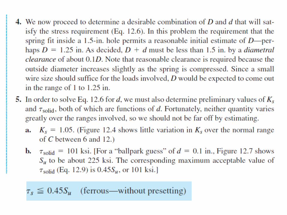


• It may be helpful to note that there are, in general, three types of problems in selecting
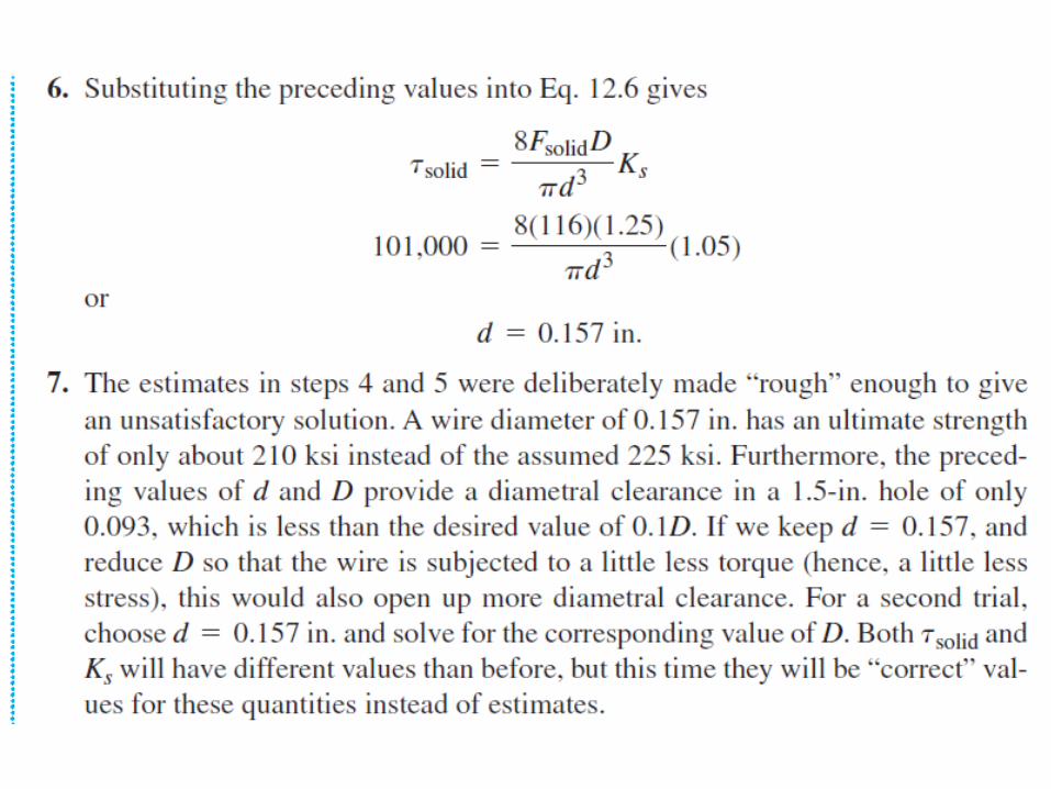
a satisfactory combination of D and d to satisfy the stress requirement.
1. Spatial restrictions place a limit on D, as when the spring must fit inside a hole or
over a rod. This situation was illustrated by Sample Problem 12.1.
2. The wire size is fixed, as, for example, standardizing on one size of wire for several
similar springs. This situation is also illustrated by Sample Problem 12.1, if steps 4,
5, 6, and 7 are omitted, and d = 0.157 in. is given.
3. No spatial restrictions are imposed, and any wire size may be selected. This
completely general situation can theoretically be satisfied with an almost infinite
range of D and d, but the extremes within this range would not be economical.
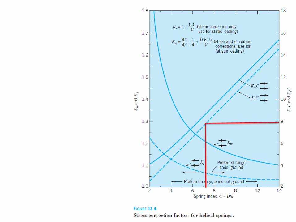
• Reference to Figure 12.4 suggests that good proportions generally require values of
D/d in the range of 6 to 12 (but grinding the ends is difficult if D/d exceeds about 9).
• Hence, a good procedure would be to select an appropriate value of C and then use
the second form of Eq. 12.6 to solve for d. This requires an estimate of Su in order to
determine the allowable value of solid.
• If the resulting value of d is not consistent with the estimated value of Su, a second
trial will be necessary, as was the case in the sample problem.

• Figure 12.12 shows a generalized S–N curve, for reversed torsional loading of round
steel wire strength Su, dia < 10 mm, Cs of 1
• A corresponding constant-life fatigue diagram is plotted in Figure 12.13. Since
compression coil springs are always loaded in fluctuating compression (and tensile
coil springs in fluctuating tension), these springs do not normally experience a stress
reversal.
• In the extreme case,
the load drops to
zero and is then
reapplied in the
same direction.
Thus, as shown in
Figure 12.13, the
region of interest
lies between a/m =
0 and a/m = 1,
where a/m is the
ratio of alternating
shear stress to mean
shear stress.

• It is customary when working with coil springs to re plot the information in Figure
12.13 in the form used in Figure 12.14. This alternative form of constant-life fatigue
diagram contains only the “region of interest” shown in Figure 12.13. Note, for
example, that point P of Figure 12.13 corresponds to m = 0.215Su, a = 0.215Su,
whereas in Figure 12.14 point P plots as min = 0, max = 0.43Su.

• Figure 12.14 is based on actual torsional fatigue tests, with the specimens loaded in a
zero-to-maximum fluctuation (a/m = 1).
• Figure 12.15 shows S–N curves based on 0-to-maxtress fluctuation. The top curve is
drawn to agree with the values determined in Figure 12.13. The lower curves in
Figure 12.15 are 0-to-max torsional S–N curves based on experimental data and
suggested for design. These reflect production spring wire surface finish, rather than
Cs = 1, as in the top curve.
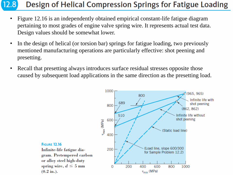
• Figure 12.16 is an independently obtained empirical constant-life fatigue diagram
pertaining to most grades of engine valve spring wire. It represents actual test data.
Design values should be somewhat lower.
• In the design of helical (or torsion bar) springs for fatigue loading, two previously
mentioned manufacturing operations are particularly effective: shot peening and
presetting.
• Recall that presetting always introduces surface residual stresses opposite those
caused by subsequent load applications in the same direction as the presetting load.
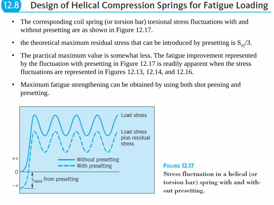
• The corresponding coil spring (or torsion bar) torsional stress fluctuations with and
without presetting are as shown in Figure 12.17.
• the theoretical maximum residual stress that can be introduced by presetting is Ssy/3.
• The practical maximum value is somewhat less. The fatigue improvement represented
by the fluctuation with presetting in Figure 12.17 is readily apparent when the stress
fluctuations are represented in Figures 12.13, 12.14, and 12.16.
• Maximum fatigue strengthening can be obtained by using both shot peening and
presetting.

• Springs used in high-speed machinery must have fn >> machine frequency.
• a conventional engine valve spring goes through one cycle of shortening and
elongating every two engine revolutions. At 5000 engine rpm, the spring has an f of
2500 cpm, and the thirteenth harmonic 32,500 cpm, or 542 Hz.
• When a helical spring is compressed and then suddenly released, it vibrates
longitudinally at its fn until the energy is dissipated by damping, this phenomenon is
called spring surge and causes local stresses approximating those for “spring solid.”
Spring surge also decreases the ability of the spring
• The natural frequency of spring surge (which should be made higher than the highest
significant harmonic of the motion involved—typically about the thirteenth) is
• For steel springs fn in Hz is
• Spring design with high fn
requires operating at high stresses
• This minimizes the required mass of the spring, thereby maximizing its fn, which is
proportional to.


38
Lecture 9
Time: M _ _ _ _14:45 - 17:30
MECH 344/M
Machine Element Design

Contents of today's lecture

• Shaft usually refers to long round member that rotates and transmits
power. Associated parts such as gears, pulleys, and cams are
attached to the shaft using pins, keys, splines, snap rings, etc.
• Shafts can be non round, or can be stationary. Can be subjected to
various combinations of axial, bending, and torsional loads - both
static or fluctuating.
• Typically, a rotating shaft transmitting power is subjected to a
constant torque (producing a mean torsional stress) together with a
completely reversed bending load (producing an alternating bending
stress).

Stresses
Kf is Kf(b) stress concentration in bending and
Kfsm is Kf(t) stress concentration in torsion

• Kf(b) and Kf(t) stress concentration factors due to
•
• Shafts must be designed to limit deflections – else hamper gear performance and
cause objectionable noise.
• The angular deflection can affect non–self-aligning bearings.
• Torsional deflection can affect the accuracy of a cam- or gear-driven mechanism.
• The greater the flexibility—either lateral or torsional—the lower the
corresponding critical speed.

• Rotating shafts carrying gears, pulleys or cams must be supported by bearings.
• If 3 or more bearings are used, precise alignment must be maintained
• Shaft axial positioning and provision for carrying thrust loads normally require
that one and only one bearing take thrust in each direction.
• If thrust load is shared among 2 or more plain thrust bearings, there must be
sufficient axial clearance to ensure against “binding” under operating conditions.
• Production tolerances may be such that only one bearing
will carry the thrust until after initial “wearing-in.”

• Gears and cams are made integral with the shaft or are made separately and then
mounted
• Hub is the portion of the mounted member in contact with shaft.
• Hub is mounted in different ways

• One method is through key for
torque transmission.
• The grooves in the shaft are called
keyways in hub keyseats.

• A simpler attachment for transmitting relatively light loads is provided by pins,
which provide a relatively inexpensive means of transmitting both axial and
circumferential loads.

• Radially tapped holes in the hub help setscrews to prevent relative motion.
• The screw diameter is typically about one-fourth the shaft diameter. Two screws
are commonly used, spaced 90 apart.
• Setscrews are inexpensive and adequate for relatively light service.
• Although special designs that provide increased protection against loosening in
service are available, setscrews should not be counted on in applications for which
loosening would impose a safety hazard.
• Setscrews may be used together with keys. Typically, one screw bearing on the
key and another bearing directly on the shaft are used to prevent axial motion.
• An excellent and inexpensive method of axially positioning and retaining hubs
and bearings onto shafts is by retaining rings, commonly called snap rings.
• Shaft snap rings require grooves that weaken the shaft, but this is no disadvantage
if they are located where stresses are low
• “push-on” retaining rings do not require grooves - low-cost, compact means of
assembling parts; but they do not provide the positive, precision positioning.
• Mating splines cut in the shaft and hub
provide the strongest connection for
transmitting torque

• Perhaps the simplest of all hub-to-shaft attachments is
interference fit
• Done with force or thermal expansion
• Rotating shafts, - running at high speeds, must be designed to avoid operation at
critical speeds. Sufficient lateral rigidity so that lowest c >> the operating range.
• When torsional fluctuations are encountered (camshafts, crankshafts) - torsional
nat freq of the shaft must be well removed from the input torsional freq - provide
sufficient torsional stiffness to make the lowest torsional natural frequency
significantly above that of the highest torsional disturbing frequency.
• Practicalities of manufacturing and operation - center of mass of a rotating system
center of rotation. So as speed is increases, centrifugal force tends to bow the
shaft. The more the bow the more unequal the centers become.
• Below the lowest (or fundamental) critical speed of rotation, the centrifugal and
shaft elastic forces balance at a finite shaft deflection.
• At c, equilibrium requires an infinite displacement of the mass center. While
damping, from the shaft bearings, reduces the displacement, this might still break
the shaft
• Rotation sufficiently above the critical speed results in a satisfactory equilibrium
position by moving the mass center toward the center of rotation.

Shaft Whirl
• In some high-speed turbines, satisfactory operation is provided by quickly going
through the c, without allowing sufficient time for an equilibrium deflection to be
reached, and then running well above the critical speed.
• c is numerically the same as the lateral natural frequency of vibration, which is
induced when rotation is stopped and the shaft center is displaced laterally,
then suddenly released. For all except the simple “ideal” case of a massless
shaft supporting a single concentrated mass, additional critical speeds at higher
frequencies are also present.
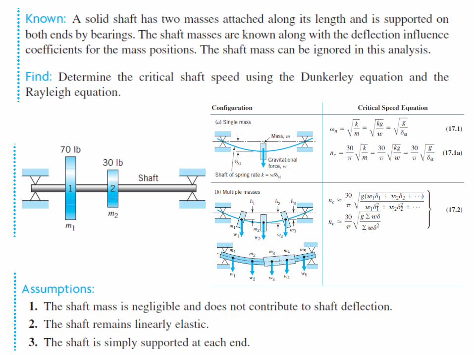
• Equations for the lowest or fundamental critical speed are in equations 17.1
through 17.3.
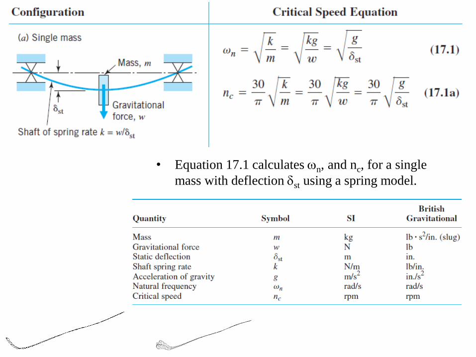
• Equation 17.1 calculates n, and nc, for a single
mass with deflection st using a spring model.

• Equation 17.3 is for calculation of n for the shaft mass only.
• Eq. 17.3 shows that for the shaft mass only distributed that nc (5/4)1/2
whereas if this distributed shaft mass is discretized into one mass acting at
the center of the shaft, nc (1)1/2 as in 17.1.

• Equation 17.2 determines nc with
multiple masses where the deflection
for each mass is known.

• With multiple masses, in Eq. 17.2, the deflection at each mass can be calculated by
superposition.
• Deflection 1 at m1 is sum of the deflections at m1 caused by each mass acting
alone; e.g., 1 = 11 + 12 + . . . + 1i
• Dunkerley’s equation (which under estimates the nc) is used to calculate the nc of
the system, using ni, of the shaft with only mass mi on the shaft
• The critical speed can be estimated
• Using 17.4 a or b
• When the critical speed of the shaft is unacceptable, the shaft diameter can be
modified using


Rad/s
n
n


• As shown in Sample Problem, shaft critical speeds can be
estimated by calculating static deflections at several points.
• Available computer programs enable calculation of static
deflections and shaft critical speeds.

Shaft Design
• Both stress and deflections need to be considered as both
could be critical
• Usually, shafts are designed based on stress considerations
and then the deflections are calculated when the geometry
is completed
• Natural frequencies in both torsion and bending are also
evaluated to avoid resonance after the geometry is
established
• If the shaft operates close to the resonance frequency, fast
failure is expected

1. Keep shafts as short as possible, with bearings close to the applied loads. This
reduces deflections and bending moments and increases critical speeds.
2. Place necessary stress raisers away from highly stressed shaft regions if
possible. If not possible, use generous radii and good surface finishes.
Consider local surface-strengthening processes (as shot peening or cold
rolling).
3. Use inexpensive steels for deflection-critical shafts, as all steels have
essentially the same elastic modulus.
4. When weight is critical, consider hollow shafts. For example, propeller shafts
on rear-wheel-drive cars are made of tubing in order to obtain the low weight–
stiffness ratio needed to keep critical speeds above the operating range.
• The maximum allowable deflection of a shaft is usually determined by critical
speed, gear, or bearing requirements.
• Critical speed requirements vary greatly with the specific application.
• Allowable shaft deflections for satisfactory gear and bearing performance vary
with the gear or bearing design and with the application

1. Deflections should not cause mating gear teeth to separate more than about
0.13 mm (0.005 in.), nor should they cause the relative slope of the gear axes
to change more than about 0.03.
2. The shaft (journal) deflection across a plain bearing must be small compared
to the thickness of the oil film. If the angular deflection of the shaft at the
bearing is excessive, the shaft will bind unless the bearings are self-aligning.
3. The shaft angular deflection at a ball or roller bearing should generally not
exceed 0.04 unless the bearing is self-aligning.
• Shaft deflections must be computed. Additionally, torsional deflections must be
considered because of torsional natural frequency requirements and necessary
limitations on torsional deflections.
• ASME std. for Design of Transmission Shafting gives non-conservative
results, as it
• assumes fully reversed bending moment load with zero mean moment load
component and steady mean torque with zero alternating torque
component.

• The more general approach is to use fatigue design of machine components.
• Determination of the fatigue strength of a rotating shaft usually requires an
analysis for the general case of biaxial loading, as summarized in Table
8.2, Figure 8.16,
• Early in the design of any given shaft, an estimate is usually made of whether
strength or deflection will be the critical factor.
• A preliminary design is based on this criterion; then the remaining factor
(deflection or strength) is checked.


RA = {1250 (60) + 500 (350)
+ 500 (50)} /400 = 687.5

Appendix d2 for
overhung loads


• Shafts supporting helical or bevel gears are subject to mean loads that include
tension or compression as well as torsion.
• Since axial stresses are functions of d2 rather than d3, a simple ratio between
ea and em for all values of d does not exist for these cases.
• The most expedient procedure is first to ignore the axial stress when solving
for d, and then to check the influence of the axial stress for the diameter
obtained.
• A slight change in diameter may or may not be indicated.
• If the diameter selected must correspond to a standard size (as in Sample
Problem 17.2D), it is likely that a consideration of the axial stress will not
change the final choice.

• Most common torque-transmitting shaft-to-hub connections are keys (square)
of standard proportions (square) - key width 1/4th of shaft diaKeys are
• Usually made of cold-finished low-carbon steel (as SAE or AISI 1020), but
heat treated alloy steels are used when greater strength is required.
• The loading of a key is a complex function of the clearances and elasticities.
• Figure a shows the loading of a loosely fitted square key. The primary loading
is by the heavy horizontal force vectors; but these tend to rotate the key CCW
until one or both pairs of its diagonally opposite corners make contact with the
keyway sides, bottoms, or both
• Figure b shows a key that is tightly fitted at the top and bottom. The horizontal
forces shown are commonly assumed to be uniformly distributed over the key
surfaces and to be equal to shaft torque divided by shaft radius.
• Both assumptions are not
correct, but in view of the
complexities and uncertainties,
they provide a reasonable basis
for design and analysis

• As an illustration of key sizing, let us estimate the length of key required in
Figure b to transmit a torque equal to the elastic torque capacity of the shaft.
• Assume that the shaft and key are made of ductile materials having the same
strength and (with the distortion energy theory), Ssy = 0.58Sy.
• The shaft torque capacity is
• The torque transmitted by compressive forces acting on the sides of the key is
the product of limiting stress, contact area, and radius:
• The torque that can be transmitted by key shear (Figure c)
is also the same:
• Equating a and b, L = 1.82d; a and c gives L = 1.57d.
• Balanced design requires the key L + 1.8d.
• Key designed for balanced compression and shear
strength would require a key depth > than key width.
• Keys normally extend along the full width of the
hub, and for good stability, hub widths are
commonly 1.5d to 2d.
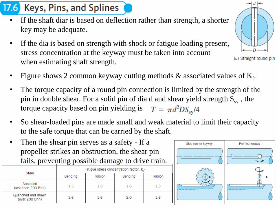
• If the shaft diar is based on deflection rather than strength, a shorter
key may be adequate.
• If the dia is based on strength with shock or fatigue loading present,
stress concentration at the keyway must be taken into account
when estimating shaft strength.
• Figure shows 2 common keyway cutting methods & associated values of Kf.
• The torque capacity of a round pin connection is limited by the strength of the
pin in double shear. For a solid pin of dia d and shear yield strength Ssy , the
torque capacity based on pin yielding is
• So shear-loaded pins are made small and weak material to limit their capacity
to the safe torque that can be carried by the shaft.
• Then the shear pin serves as a safety - If a
propeller strikes an obstruction, the shear pin
fails, preventing possible damage to drive train.

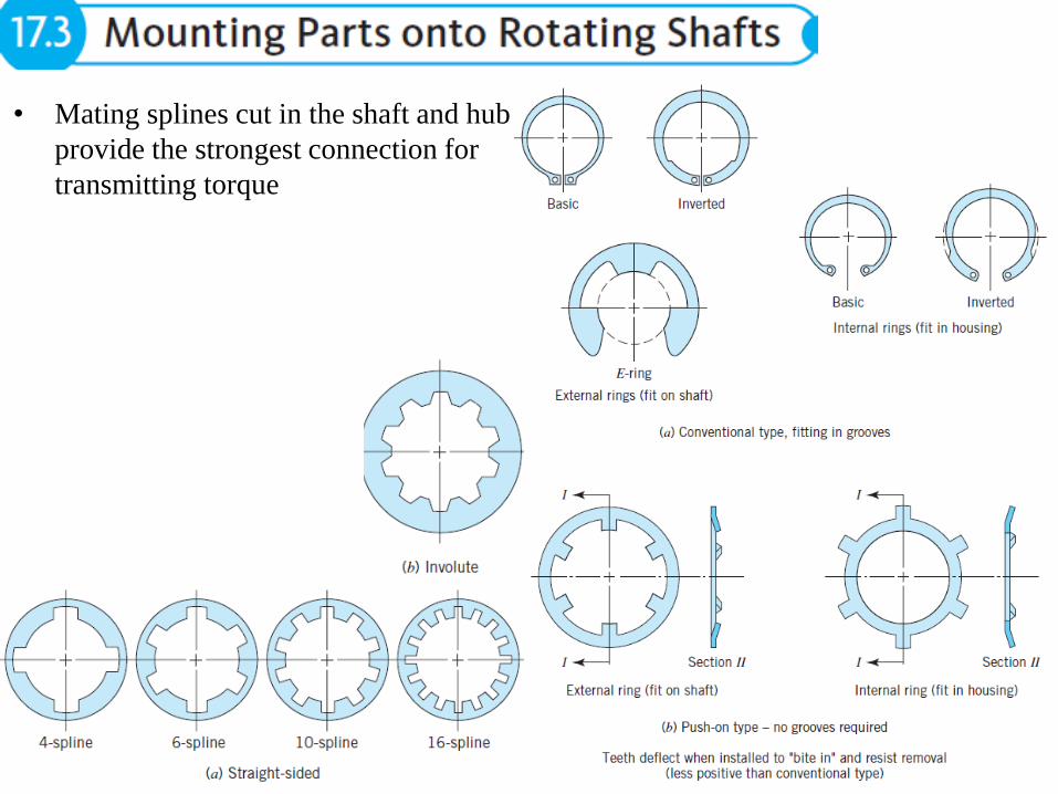
• Splines act like multiple keys. They have either involute or straight-sided
profiles, the former being the usual type in modern machinery.
• Involute splines usually have a 30 pressure angle, and one-half the depth of
standard gear teeth (other standard are 37.5 and 45).
• The fit between mating splines is characterized as sliding, close, or press.
• Figure 17.14 shows a sliding-fit spline that permits the length of an automotive
propeller shaft to change slightly with rear-wheel jounce.
• Splines can be cut or rolled onto a shaft. The strength of a splined shaft is
usually taken as the strength of a round shaft of dia = the minor dia of spline
• However, for rolled splines, the favorable effects of cold working and residual
stresses may make the strength nearly = to that of the original unsplined shaft.

• Colinear shafts can be joined by rigid couplings - The
coupling halves attached to the shaft ends with keys, or
slotted tapered sleeves.
• The flanged portions at the outside diameter serve a safety
function by shielding the bolt heads and nuts.
• For designing such a coupling, the force flow concept leads to consider, (1) the
torque capacity of the key or wedged, (2) the strength of the relatively thin web
portions that are drilled to accommodate the bolts, and (3) the strength of the
bolts.
• Rigid couplings are limited to rare instances where shafts are colinear within
extremely close tolerances and stay that way.
• If shafts are laterally or angularly misaligned, the installation of a rigid
coupling forces them into alignment.
• This subjects the coupling, shafts, and shaft bearings to unnecessary loads that
may lead to early failures.
• This can be eliminated by flexible couplings

• Figure shows a few of the many designs that use a flexible
material like rubber.
• These can be designed to provide elasticity and damping for
control of torsional vibration & providing for misalignment.
• Other flexible couplings use all metallic
components, and these tend to have greater
torque capacity for a given size.

• One design of fairly ancient origin is the Oldham coupling, shown in Figure
• The sliding of the center block permits a substantial amount of shaft lateral offset,
and built-in axial clearance permits some angular misalignment.
• Universal joints permit substantial angular misalignment- Figure shows the
common type (Cardan or Hooke’s joint) used at the ends of rearwheel-drive auto.
• Plain bushings or needle bearings are used at the yoke-to-cross connections. If
the input yoke rotates at constant angular velocity, the output yoke velocity will
have a speed fluctuation at twice rotating speed, the magnitude of which
increases with the misalignment angle.

• If two joints are used, with yokes aligned as shown in Figure, speed fluctuations
across the two joints cancel to give uniform output yoke rotation if all three shafts
are in the same plane, and if the misalignment angles at the two joints are equal.
• Other types of universal joints that transmit angular velocity uniformly across a
single joint have been devised. These are known as CV universal joints.
• Common application is in front-wheel-drive auto, where drive shafts are short,
and shaft angles (steering and wheel jounce) can be large.

• To protect persons from rotating universal joints, couplings, and shafts, machine
guards are generally required. Figure shows coupling guard for pump assembly.
• Coupling and shaft guards provide physical protection from the rotating
components, and when properly designed can be opened or removed to service
the connected equipment
• The guard can also protect couplings and shafts from external and environmental
damage.


