Download - 1 HAP Smart Antenna George White John Thornton, Yuriy Zakharov, David Grace University of York

1
HAP Smart Antenna
George White
John Thornton, Yuriy Zakharov, David Grace
University of York

2
HAP smart antenna - Introduction
Research motivations:
• Flexible way of achieving spatial re-use– adapt power and bandwidth distribution on ground according to positions of users
• Compensation for HAP motion • New beamsteering scenario:
– steering in elevation as well as azimuth, c.f. terrestrial large steering angles, c.f. GEO satellite
• ‘Smartness’ – interference suppression

3
HAP smart antenna - Issues
Number of elements, M:
Large M:– allows significant spatial re-use of bandwidth– increases directivity for HAP-Earth link– increases complexity (simulation and implementation)
So far, M=64 elementsSignificant capacity enhancement if applied to existing TDM or FDM downlinkSufficient directivity (link budget has been developed)Relatively easy to analyse

4
HAP smart antenna - Issues
Degree of ‘smartness’:
• Simple: Multiple fixed beam directions.Could provide cellular coverage.
• Moderate: Beam steering wih fine angular variationsCan compensate for HAP motionCapacity increase is limited - interference can be highwhen co-channel users are in sidelobes
• Truly smart: Null steering Place co-channel users in beampattern nullsIncreased complexity, particularly for high M
5
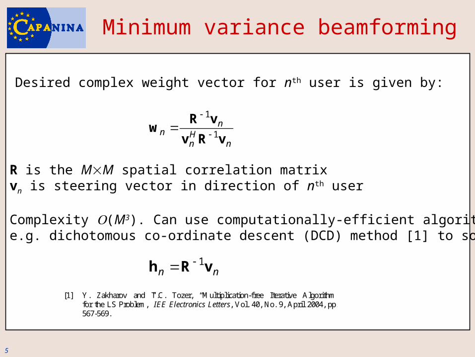
Minimum variance beamforming
nHn
nn
vRv
vRw
1
1
R is the MM spatial correlation matrixvn is steering vector in direction of nth user
Complexity (M3). Can use computationally-efficient algorithms, e.g. dichotomous co-ordinate descent (DCD) method [1] to solve:
Desired complex weight vector for nth user is given by:
nn vRh 1
[1] Y. Zakharov and T.C. Tozer, “Multiplication-free Iterative Algorithm for the LS Problem,” IEE Electronics Letters, Vol. 40, No. 9, April 2004, pp. 567-569.
6
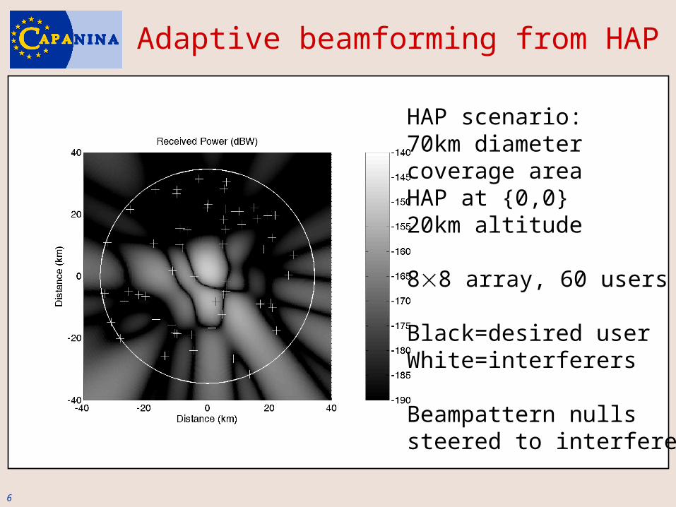
Adaptive beamforming from HAP
HAP scenario:70km diameter coverage areaHAP at {0,0} 20km altitude
88 array, 60 users
Black=desired userWhite=interferers
Beampattern nullssteered to interferers

7
HAP beamforming:Performance in ideal case
CDF of SIR on the downlinkfor a single, reference user
N users, M elementsIdeal case:Perfect knowledge ofHAP and user positions
N<<M, strong interferencesuppression, high SIR
NM, degradation in SIR
Note: This provides spatial re-use gain. Use alongside frequency or time re-use

8
HAP beamforming:Performance with position and attitude errors
GNSS positional informatione.g. GPS, assume averageaccuracy to within 15m
Small, uncompensatedvariations in HAP attitude(e.g. pitch, roll or yaw)may be a limiting factoron capacity. E.g. due to turbulence
= standard deviation of zero-mean Gaussian-distributedpitch variation (degrees)
9
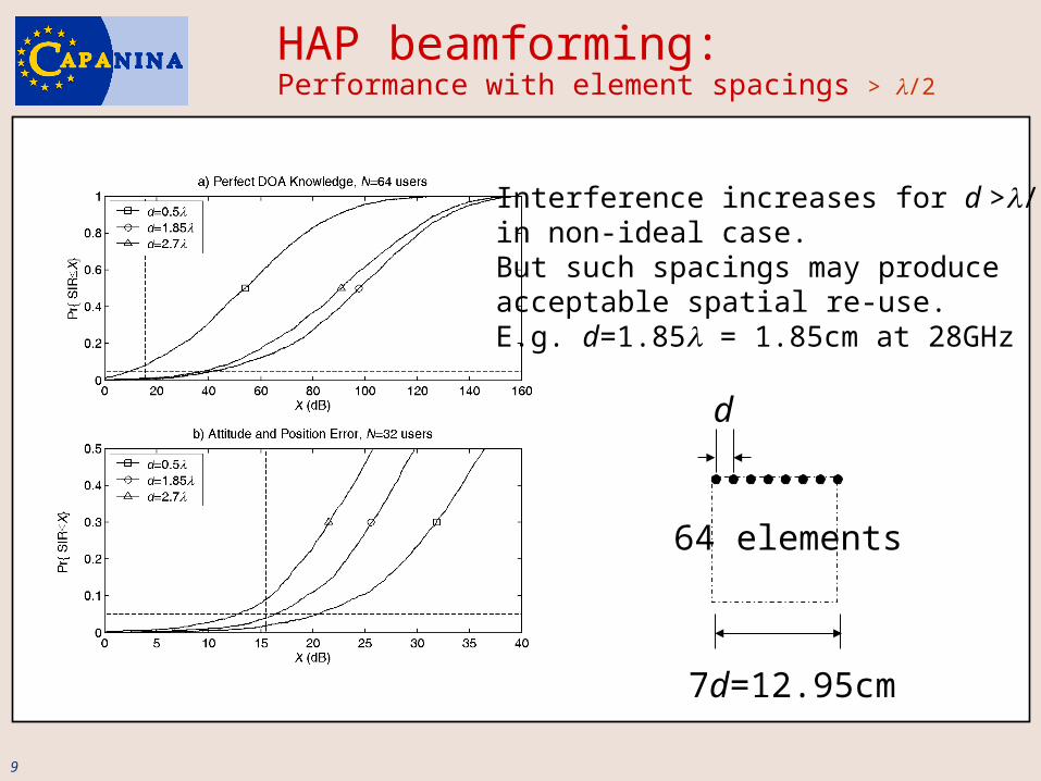
HAP beamforming:Performance with element spacings > /2
d
7d=12.95cm
64 elements
Interference increases for d >/2 in non-ideal case.But such spacings may produceacceptable spatial re-use.E.g. d=1.85 = 1.85cm at 28GHz

10
Array configurations
e.g. d=0.5 where =1cm (f=28GHz)
d
7d=3.5cm
64d/=10.2cm
8d=4cm
64 elements64 elements
rings of:1, 6 ,12, 18, 24
d
d
61 elements
rectangularcircular array,
circumferential elements circular array, filled

11
Array configurations – Pros and cons
• Rectangular or circular, filled arrays:– Lack of space for component placement if d =/2 – Robust to position or attitude errors if d =/2
• Circular array, circumferential elements:– More space available for component placement– Could ensure equal length LO feeds– Performance degradation with position or attitude errors

12
Beampatterns:Circular array, circumferential elements
No interferers 59 interferers

13
Beampatterns:Circular array, filled
No interferers 59 interferers

14
Journal submission/Further work
"Adaptive Beamforming for Communications from High-Altitude Platforms", George White, John Thornton, David Grace, Yuriy Zakharov and Tim Tozer submitted to IEEE Trans. on Wireless Comms., Feb. 2005.
• Reduced complexity (DCD) minimum variance beamforming• Channel allocation methods for HAP beamforming• Comparison of cellular and single-user-per-beam coverage strategies• Performance of beamforming over Capanina HAP channel model• Alternative array configurations (contd.). E.g. tilted arrays
RAF Fylingdales, N. Yorks, UK
Sectorised coverage area


