
-TT'
ILLS AZ"P
AMR T 71
STDIS FTETUE EELPMN
AMMR CR77 -
By Hsun Hu
United States Steel CorporationResearch LaboratoryMonroeville, Pennsylvania 15146
Final Technical qeort D D CConwt Nsjmtur OAAOIS.77.O.0014 D 7 p.-7r,
AU'22 1977ITAApproved for public release; distribution unlimited. jPrepared for
ARYMATERIALS AND MECHANICS RESEARCH CENTER-fiatertown, Massachusetts 02172
-JJ

The findings in this report are not to be construed as an official
Department of the Army position. unless so designated by other
authorized documents.
Mention of any trade names or manufacturers in this report
shall not be construed as advertising nor as an official
indorsement or approval of such products or companies by
the United States Government.
DISPOSITION INSTRUCTIONS
Dwroy this report when it is no longer needed
Do not return it to the Origrntor.

I "
AMjRCTR-77-19
._ STUDIES OF JEXTURE EVELOPMENTIN STEEl ARMOR PLATE.
J 7 /07
BY: Hsun/1Hu , I/ United States Steel Corporation
Research LaboratoryMonroeville, Pennsywvania 15146
Final Technical Report -. - /Co tract Number DAAG4&-77-C.0014
Approved for public release; distribution unlimited.
Prepared for
ARMY MATERIALS AND MECHANICS RESEARCH CENTERWatertown, Massachusetts 02172
,-; , / /7

Table of ContentsPage
Foreword iiList of Tables iiiList of Illustrations iv
Abstract 1Introduction 2Materials and Procedures 4
Steel Composition and Ingot Dimensions 4
Hot Rolling Procedures 5
Material for the 6- by 12- by %1/2-Inch Plates 5Having (112) + (111) Texture
Exploratory Specimens for Producing Nearly (111) 9Texture by Quenching Cross-Rolled Austenite
Results and Discussion 10
Texture of the 6- by 12- by 1t/2-Inch Plates 10
Microstructure and Hardness of the 6- by 12- by 11\'i/2-Inch Plates
Ballistic Performance of the 6- by 12- by "i/2-Inch 13Plates
Texture of the Cross-Rolled Specimens 14
Microstructure and Hardness of the Cross-Rolled 16Specimens
Summary and Conclusions 17Future Work 18Acknowledgements 18References 19
Appendix A
FY
"C[S
I II II~ I " III- -

FOREWORD
This report was prepared by the Research Laboratory
of United States Steel Corporation under U. S. Army Contract
No. DAAG-46-77-C-0014 . The contract was administered by the
U. S. Army Materials and Mechanics Research Center, Watertown,
Massachusetts, Anthone Zarkades-Contracting Officer Represen-
tative. This is a final report and covers work conducted
from January 20 to June 20, 1977.

List of Tables
Table
1 Chemical Composition of Armor Steel in Weight Percent
II iardness of the Plates Rolled to Various Reductions at1500*F then Quenched and Tempered
III Ballistic Performance of the Plates Rolled to VariousReductions at 1500°F then Quenched and Tempered.Texture Type (112) + (ill)
IV Summary of Information on Exploratory Specimens Cross-Rolled to Various Reductions at 1500*F then Quenchedand Tempered
iii
... .. . . . . I. .. I ' IIJ

List of Illustrations
Figure
1 (110) Pole Figures of the Plates Rolled to VariousReductions at 1500OF then Quenched and Tempered(Ingot 705). A. 60%; B. 70%; C. 80%; and D. 90%.
2 (200) Pole Figures of the Plates Rolled to VariousReductions at 1500°F then Quenched and Tempered(Ingot 705). A. 60%; B. 70%; C. 80%; and D. 90%.
3 Microstructure of the Plate Rolled 60% at 15000F thenQuenched and Tempered (Ingot 705). Nital Etch. X500.
4 Microstructure of the Plate Rolled 90% at 1500*F thenQuenched and Tempered (Ingot 705). Nital Etch. X500.
5 Correlation of the Ballistic Limit with the Intensityof (112) + (111) Texture.
6 (110) Pole Figures of the Specimens Cross-Rolled toVarious Reductions at 15009F then Quenched andTempered. A. 60%; B. 70%; C. 80%; and D. 90%.
7 (200) Pole Figures of the Specimens Cross-Rolled toVarious Reductions at 1500°F then Quenched andTempered. A. 60%; B. 70%; C. 80%; and D. 90%.
8 (222) Pole Figure of the Specimen Cross-Rolled 90% at1500*F then Quenched and Tempered.
9 Microstructure of the Specimen Cross-Rolled 60% at1500°F then Quenched and Tempered. Nital Etch. X500.
10 Microstructure of the Specimen Cross-Rolled 90% at15006F then Quenched and Tempered. Nital Etch. X500.
iv
L -1 i.. .. I I I

Studies of Texture Development inSteel Armor Plate
by
Hsun Hu
Abstract
The present research program consisted of two parts. (1) To
produce a number of 6- by 12- by nl/2-inch armor plates having strong
(112) + (111) texture with various degrees of intensity by the thermo-
mechanical processing treatments of essentially the same medium-
carbon, 5Ni-Si-Cu-Mo-V steels used previously, and to establish the
reproducibility of texture, maicrostructure, hardness, and ballistic
performance of these steel armor plates. Results indicated that the
reproducibility of the structure and properties of these steel armor
plates was excellent. The ballistic limit increased with the texture
intensity in nearly the same manner as observed previously. (2) To
explore the possibility of producing a nearly (111) texture with
various degrees of intensity in small-size specimens cross-rolled
at 1500*F to various reductions then quenched, and to establish a
procedure for optimizing this texture in larger 6- by 12- by 'l/2-
inch plates. Results indicated that the texture obtained was L223j
<032>, which is about 11 degrees from {1ll>l011>, close to that pre-
dicted. The development of this texture should be possible in larger
6- by 12- by -1/2-inch plates that can be used for the testing of
mechanical and ballistic properties.

I-2-
Introduction
Results from a recent investigation on the effect of
crystallographic texture on the ballistic performance of a medium-
carbon 5Ni-Si-Cu-Mo-V steel indicated that the V50 ballistic limit
of the (112) + (ill) textured plates was substantially higher than
that of random-textured plates at approximately the same hardness.
Furthermore, the improvement in the ballistic limit increased with
the texture intensity. To assure reproducibility of the results,
and to enable more extensive studies with these textured plates, it
would be desirable to produce a number of additional 6- by 12- by
-1/2-inch armor plates with various degrees of the (112) + (111)
texture. These plates could be used for a variety of additional
studies of the mechanical and ballistic propvrtics not comprehended
1)in the earlier investigation so that such textured plates could
be fully characterized.
It is well known that the Young's modulus, E, of iron or
2)steel is the highest in the [1111 direction, and that ti stress
intensity of the reflected tensile wave upon impact deformation is
1/2 3)proportional to E/, whereas the cleavage stress if roughly
4'proportional to E. Thus, a strong (111) texture in the plane of
the plate may further improve the ballistic performance of the
plate. From the available data on the texture behavior of common
*See References.

fcc metals, and the orientation relationship of austenite to
martensite in steels, it appears feasible to produce a nearly
(111)-textured steel armor plate by appropriate thermomechanical
processing treatments.
As is well known, the orientation relationship between
the austenite and the martensite resulting from phase transforma-
5)tion is that of the Kurdjumov-Sachs, which has 24 crystallo-
graphically equivalent variants. These can be expressed in the
generalized form:
'11 0. <11> <110>a
or
<1f0> <1 <11> f:llO! !111
since, for cubic lattices, the indices of planes and directions
are identical. Thus, to produce a plate nearly (111) oriented in
the plane of the plate (or a [111]-textured plate with a [111] axis
normal to the plate), a strongly (110)-oriented austenite will have
6)
to be produced. It was recently shown by Davies et al. that such
orientation-related transformation textures can be predicted satis-
factorily without variance selection by using the crystallite
orientation distribution functions of Roe.
7 )
Some time ago Merlini and Beck 8 ) showed that the texture
of heavily cross-rolled copper is predominantly (110) [223]. The
same kind of cross-rolling texture should be developed, and was
observed, in fcc alloys of low stacking-fault energies, such as the
9)70-30 brass. Thus, heavy cross rolling of the armor steel in the

'4I
austenite region withou;t concurrence of recrystallization, for
exam~ple at 15009F (8160C), should develop a strong (110) texture
in the plane of the plate. Upon immediate qiuenchinq of the cross-
rolled austenite, it should b~e possible to produce a strongly (111)-
texturedi martensite in the armor plate.
The present research program, under a five-month interim
contract awarded by the Army Materials and Mechanics Research Center
to the Lnited States Steel Research Laboratory tContrac t No. DAAG-
46-77-C-0014), consisted of two parts: (1) To produce a number of
6- b- 12- by A-/2-inch armor plates havinq; a I-tronq (112) +- (111)
texture with various degrees of intensity, and to check the re-produci-
bility of earlier results in texture, microstructure, hardness, and
ballistic properties; and (2) to exl-:Iore the Possibility of producin-;
a strong (11l) texture with various doJrees of intensity in small-
size specime:is, and to establish a procedure "Or optimizi' tis
texture in 6- by 12- by 1. 12-inch plates.
Materials and Procedures
Steel Composition and inclot Dimensionz
For the first part of the research :progjra-.-, namely, tc
produce a number of 6- by 12- by l,2-inch armor plates ha\'Inc: a
strong C112) + (111) texture of variois mrntens'tlics and to establis-
the reproducibility -)f earlier retsults, threc 500-pound (227 k o)
heats of nominally the sarme chemical ono io as that of thle
steel used previously, L)w(-re vacuumj~-mel! ted and cAst at t:ie Laxra-
to ry The ,not.s, )~no from each heat, were o' ~ sam~e a.:s0

-5-
as those in aarlier ilnvestigations, 7 by 12 by 24 inches (180 by
300 by 600 mm). Check analyses of samples taken from the hot-rolled
plates, 0.55 inch (14 mm) thick, are shown in Table I. Within narrow
variation limits, these compositions matched closely with those of
earlier steels.
For the second part of the present program, that is, to
explore the possibility of producing a strong (111) texture with
various degrees of intensity in small-size specimens, some of the
trimmed-off edge material from the intermediate plates (2-1/8-in.
thick) left over from the earlier investigation1 ) was used.
Hot-Rolling Procedures
Material for 6- by 12- by "-1/2-Inch Plates Having (112) +
(ill) Texture. For producing the (112) + (111) textured plates of
various intensities, the preliminary hot rolling of the ingot to the
various intermediate thicknesses and the final isothermal rollino to
a common plate thickness after various reductions were conducted in
1)ex'ctly the same manner as described previously. However, some
minor modifications were employed for one or all three ingots in
the method of cooling of the intermediate pieces and in the reheat-
ing temperature for final isothermal rolling. These modifications
were adopted mainly to improve the processing conditions, anJ i'ro-
duced no significant efiects on the texture and properties.
For preliminary hot rolling to the various intermediate
thicknesses, namely 5.50, 2.75, 1.85, and 1.40 inches '140, 70, 47,
and 36 mm) , the ingots were hot-charged into a pceheatin7 furna-e

-6-
at 2250OF (1230 0 C), soaked for two hours, and then rolled from
the 7 inches of the ingot thickness to a sl 'D of 5.50 inches. A
predetermined length was torch-cut from the bottom end of the
slab, and the remaining slab was then reheated to temperature in
the furnace. After about 15 to 20 minutes reheating, the slab was
again rolled to the next intermediate thickness (2.75 inches) and
another prerdetermined length was torch-cut from the previously cut
end of the piece. The reheating, hot-rolling, and torch-cutting
procedures were repeated until the piece was finally rolled to
'..40 inches in thickness.
Fcr the first two ingots (No. 705 and 706, Table I),
these intermediatod pieces were all cooled in air, the practice1)
employed in the previous investigation. When the intermediate
pieces were later cut by abrasive cut-off wheel along the midwidth
line so that each piece became two 6-inch-wide halves, hairline
cracks were always observed on the cut-off faces. As will be
described later, these hairline cracks may have been responsible
for some edge cracking during the next rolling. ro control the
temperature in final roiling, a small hole (5/32 inch or 3 mm in
diameter) for insertion of a thermocouple was drilled in each piece
on the cut-off face at approximately the midposition of thickness
and width by electrical discharge machining (EDM), because the
material was too hard to be drilled in an ordinary drill press.
The hairline cracks and the high hardness of the inter-
mediate pieces indicated that the steel was Dracticall: hardenrhie
.....................................

7 -
by cooling in air, and that the volume change in phase trans-
formation was probably responsible for the hairline cracks
observed on the cut-off faces. It was noted that in the finally
rolled and quenched plates some edge cracking (mostly about 0.5
inch in ,th) occurred on the prior cut-off side of the inter-
mediate pieces. This suggested that the hairline cracks in the
intermediate pieces had induced edge cracking in the final plates.
in an attempt to eliminate the hairline cracks in the
intermediate pieces, hence the occurrence of some edge cracking in
the final plates, the intermediate pieces from the third ingot
(No, 717) were cooled in vermiculite. No hairline cracks were
observed on the cut-off faces and the thermocouple holes were
drilled in an ordinary drill press without difficulty. It was
obvious that cooling the steel slowly in vermiculite resulted in
the formation of the high-temperature transfornmation products
together with some tempered martensite and bainite in the inter-
mediate pieces.
In the final rolling treatment, the intermediate pieces
from all three ingots were reheated for two hours at 1650OF (9000C)*,
rolled isothermally at 1500*F (8160 C) to a final thickness of 0.55
inch (14 mm), and water-spray-quenched to room temperature. This
procedure resulted in reductions in thickness of 60 to 90 percent
*This reheating temperature was slightly lower than that used pre-
viously (17000F). It was adopted purposely to reduce the coolinc
time required to the isothermal rolling temperature of 1500'F. Fcr
the slowly cooled intermediate pieces of Ingot 717, this reheatingtime and temperature were found adequate to reaustenitize the steel.

for the intermediate piecez 1.40 to 5.50 inches thick, respectively.
1)As was the case in the previous investigation, for the inter-
mediate pieces of sma2l -hicknesses (1.40 and 1.85 inches) no
difficulty was encounte cooling the piece on the run-off table
from the reheating temperature of 1650°F to the isothermal rolling
temperature of 1500°F before starting to roll. Isothermal conditions
were closely approximated by using a predetermined program of varying
amounts of reduction per pass so that the heat lost by radiation and
convection was nearly balanced by the heat generated during deforma-
tion. For the more massive pieces (2.75 and 5.50 inches thick),
it was necessary to start rolling at a somewhat higher tempexature
than the desired isothermal rolling temperature of 1500*F (rolling
started at around 1575 and 1600*F as indicated by the inserted thermo-
couple) so that the corners and edges of the piece would not be
cooled excessively in comparison with the interior, resulting in
nonuniform deformation or severe difficulties in the rolling opera-
tion. However, the somewhat higher start-rolling temperature was
gradually reduced to the desired rolling temperature in the first
few passes. The slightly lower reheating temperature used in the
present investigation, hence shorter waiting time for start of
rolling, should have assisted in attaining more uniform deformation
in the fi-.al plates.
Whereas the plates from the first two ingots (No. 705 and
706) showed some edge cracking on the prior cut-oft side of the
intermediate pieces, those from the third ingot (No. 717) were free

- 9 -
from such defects. The slower cooling rate (cooled in vermiculite
vs in air) applied to the intermediate pieces of the third ingot
was apparently responsible for this improvement.
Exploratory Specimens for Producing Nearly (111) Texture
by Quenching Cross-Rolled Austenite. Small blocks having dimensions
of approximately 1.5 by 1.5 by 0.5 or 1.0 inches (%38 by 38 by 13
or 26 mm) were cut off from the edge material left over from the
earlier investigation. The 0.5-inch-thick blocks were used for
cross rolling to 60 and 70 percent reductions in thickness, whereas
the 1.0-inch-thick blocks were used for 80 and 90 percent reductions.
The final thicknesses of these exploratory specimens produced for
texture, microstructure, and hardness examinations were thus 0.20
to 0.10 inch (5.1 to 2.5 mm).
For isothermal cross rolling at 1500 0 F, the steel block
was heated in a preheating furnace at 1700OF and held at tempera-
ture for 15 minutes. The piece was then transferred to another
furnace set at 15000 F. When the specimen reached this temperature,
it was taken out and rolled in the first rolling direction
(designated as RD,) with a predetermined amount of reduction. The
specimen was put back into the furnace to restore the temperature.
For the second rolling pass, the specimen was rotated 90 degrees
from the initial orientation before entering the rolling mill. The
amount of reduction in the second rolling direction (designated as
RD 2) was the same as in the previous pass in the first rolling
direction. These procedures were then repeated until the final

- 10 -
thickness was reached. The total reduction in RD and RD2 was12
made the same in each specimen. Immediately after the final pass
in RD-, the specimen was quenched in water.
As a standard practice in the previous and present inves-
tigations, all the quenched materials were given a tempering treat-
ment of 1 hour at 350*F followed by cooling in air before examina-
tions for structure and properties. For ballistic tests, the
tempered plates were surface-ground to 0.5 inch or less in thick-
ness to remove oxide scale and decarburized material in the subsurface
layers. Sixty-six 6- by 12- by -I/2-inch plates, identified in
LAppendix A, were shipped to the Army Materials and Mechanics Research
Center for ballistic testing and other mechanical and metallographic
studies by the Army.
Results and Discussion
Texture of the 6- by 12- by 1/2-Inch Plates
The crystallographic textures of the plates were examined
by X-ray pole figures determined from the midthickness section.
Specimens of plates rolled to various reductions from the three
ingots were all examined. For the first two ingots (No. 705 and
706), both the (110) and (200) pole figures were determined by the
Schulze reflection technique up to a tilt angle of 80 degrees from
the rolliny-plane normal, using filtered MoK radiation. For the
third ingot (No. 717), only the (110) pole figures were determined.
The nature and degree of intensity of the textures were similar to
1)those in the plates processed in the earlier investigation.

In fact, the ii.tensity maxima, as shown by the (110) pole figures
of the present plates, particularly those rolled to high reductions,
were appreciably higher than those observed previousl;. The
reason for this observed increase in texture intensity for the
present plates is not clear. The somewhat higher inclusion con-
tents (as shown by the microstructures to be described in the next
section), which could be an indication of higher oxygen contents
actually present in the steels, may have retarded the rate of
recovery during hot rolling; this resulted in higher X-ray diffrac-
tion intensity.
In Figures 1 and 2, the (110) and (200) pole figures,
respectively, of the plates rolled 60 to 90 percent from Ingot 705,
are presented. Those of correspondingly rolled plates from Ingot
706 or 717 were quite similar except that the intensity maxima were
somewhat lower. As can be noted from these pole igures, the nature
of the texture was a strong (112) + (111); and the texture intensity,
as indicated by the average intensity maxima of the (110) pole
figures, increased with rolling reduction from 3.75 at 60 percent
reduction to 9.05 at 90 percent reduction.
Microstructure and Hardness of the 6- by 12- by -il/2-inch Plates
The microstructures of the 6- by 12- by "i/2-inch plates
rolled to various reductions from the three ingots were examined
on the longitudinal and transverse sections by light microscopy.
in accordance with previous observations, the structure is all
martensitic and consists of bands lying nearly parallel to the
rolling plane, elonlated most prominantly in the rolling direction.

-12-
Figures 3 and 4 show the photomicrographs of the plates rolled 60
and 90 percent, respectively, of Ingot 705. The plates rolled to
70 and 80 percent reductions had similar structural features, as
did the corresponding plates from the other two ingots (No. 706
and 717). Such structural bands were believed to represent the
textural components and not the reduced thicknesses of the prior1)
austenite grains after rolling reductions. The thickness of the
structural bands was nonuniform, and the average band thickness
appeared to decrease slightly with increasing reduction.
Upon examination of the microstructures of the various
plates rolled from the present three ingots, it was noticed that
the inclusions were apparently more numerous than in the steels1)
used in the previous investigation. These inclusions were
particularly evident when the polished surfaces were examined
before etching. Even on the etched surfaces, such as the photo-
micrographs shown in Figures 3 and 4, scattered dark patches where
inclusion particles were located can be noticed. However, these
-J
structural features were not indicated by the results of chemical
analysis (Table I), except for the unusually high oxven content
reported for one of the samples (Footnote under Table I).
The hardness of the various plates was measured on the
metallcgraphic specimens. Ten measurements of the DPH numbers
were made (5 on the longitudinal and 5 on the transverse sections)
for each plate. The average values of these measurements, converted
to the RC scale, are shown in Table II. The hardness values measured

- 13 -
on the longitudinal section of the specimens were slightly but
consistently higher than those on the transverse section, suggest-
ing anisotropy due to preferred orientations. These hardness
values agree well with those observed for the armor-steel plates
processed previously. 1)
Ballistic Performance of the 6- by 12- by %l/2-inch Plates
One plate for each rolling reduction from each of the
three ingots processed was tested for the V5 0 ballistic limit with
0.50 caliber projectiles at zero degree obliquity. The results,
together with the texture intensity, hardness, and thickness of the
plates, are summarized in Table III.
10)It was recently suggested by K. H. Abbott of AMMRC
that the ballistic data of textured plates obtained in the previous
investigation1 ) could be shown more meaningfully as a function of
texture intensity, including random-textured plates (texture-
intensity parameter being equal to 1.00), after corrections were
made to d uniform plate thickness. The thickness correction factor
was 10 fps in ballistic limit per 0.005 inch of plate thickness
(taken from MIL S-12560). Abbott showed that the corrected ballistic
limit had a linear dependence on the texture intensity, with a
scatter band of about 100 fps on either side of the mean ballistic
limit, which is rouyhly equivalent to a standard deviation of
a = 30. As pointed out by Abbott, this is an important point
because ballistic-limit data that have been subjected to statistical
analysis by the Test and Evaluation Command at APG for homoQenecus

steel armor of "uniform good quality" agaiist the caliber 0.50
APM2 at 0 obliquity had a standard deviation on the order of
30 fps.
Following the same procedures for plate-thickness
corrections, the V50 ballistic limits of the present textured
plates were plotted against the texture-intensity parameter. The
results are shown in Figure 5 together with the ballistic test
results of previous investigations after corrections for plate
thickness. Most of the data points are within the scatter band.
Only a few data points fall slightly outside the band, indicating
somewhat wider scatter of the textured plates. However, the trend
for the ballistic limit to increase substantially with the intensity
of the (112) + (111) texture is clearly indicated by these results.
As observed previously, back spalling appears to occur
frequently in strongly textured plates uporn ballistic testing.
Structural banding along the thickness direction and parallel to
the rolling plane of the plate (see Figures 3 and 4), which is
believed to be associated with the texture components present in
the plate, may have been responsible for the low back-spalling
resistance of the textured plates.
Texture of the Cross-Rolled Specimens
The crystallographic texture of the snall-size specimens
cross-rolled to various reductions at 1500°F then quenched and
tempered were examined on the midthickness section. Figures 6 and
7 show, respectively, the (110) and (200) pole figures. As
II. ... ...] .... . .....

expected from cross rolling to nearly equal strains in both
rolling directions (RD1 and RD2), the pole figures show approxi-
mately the same symmetry with respect to either rolling direction
even though the texture, as shown, is that of the martensite
transformed from the cross-rolled austenite.
As a consequence of this apparently high symmetry of the
pole figures, one may easily be misled to a first impression that
the texture is of a (100) or (110) type since the rolling plane
has a four-fold or a two-fold symmetry with the reflection planes.
That the texture of these cross-rolled specimens actually had a
high concentration of approximately (111) planes in the plane of
rolling is shown more convincingly by the (222) pole figure in
Figure 8. The texture is mainly (223) [032), which is only about 11
degrees from (111)[OlT] with respect to either of the two rolling
directions. Hence, the prediction of the texture of the martensite
that is produced by transformation of cross-rolled austenite, based
simply on the Kurdjumov-Sachs orientation relations, was confirmed.
The intensity of the texture of all these cross-rolled
specimens was low. This is believed to be due to the reheating of
the specimen between passes during rolling, a procedure necessary
for isothermal rolling of small-size specimens. It is obvious
that duriny this reheating extensive recovery, and hence a reduc-
tion in the dislocation density, occurs. Consequently, as the
perfection of the crystallites increases, the intensity of the
diffracted X-ray decreases because of increased primary extinction.
L __

- 16 -
When the isothermal condition can be controlled in rolling
larger pieces, such as the 6- by 12-by "4/2-inch armor plates,
the intensity of the texture should be substantially increased.
Even with the relatively low texture intensities of the present
cross-rolled specimens, the intensity of the texture showed
increases with rolling reduction (see Table IV).
Microstructure and Hardness of the Cross-Rolled Specimens
The microstructures of the two cross secticons of the
small-size specimens cross-rolled to 60 and 90 percent reductions
in thickness are shown in Figures 9 and 10, respectively. As a
consequence of. the approximately equal amount of reduction in each
of the two orthogonal rolling directions, the microstructures of
the two cross-sections are almost indistinguishable. The structural
banding, even in the specimen cross-rolled 90 percent (Figure 10),
is much less markedly defined than in the straightaway-rolled
specimen (Figure 4). As was postulated earlier, the low resistance
to back spalling in strongly textured armor plates (produced by
straightaway rolling to high reductions then quenched and tempered)
1)is belicved to be due to the structural or textural bandinG. It
would therefore be interesting to see whether the heavily cross-
rolled 6- by 12- by -1/2-inch plates, when produced in the future,
would show higher resistance to back spalling upon ballistic
testing.
The hardness and other technical information of the cross-
rolled specimens is summarized in Table IV. The average hardness

17 -
of the cross-rolled specimens appears to be somewhat higher than
that of straight-rolled 1/2-inch-thick armor plates at the same
amount of rolling reduction. However, these differences may have
been a consequence of effective quenching because the thicknesses
of the cross-rolled exploratory specimens (0.10 to 0.20 inch) were
substantially less than those of the 1/2-inch-thick armor plate.
Summary and Conclusions
The first part of the present research program was to
produce a number of 6- by 12- by '1I/2-inch armor plates having
strong (112) + (111) texture with various degrees of texture
intensity by the thermomechanical processing treatments of
essentially the same medium-carbon, 5Ni-Si-Cu-Mo-V steels as used
I)previously, and to establish the reproducibility of texture,
microstructure, hardness, and ballistic performance of these steel
armor plates. Results indicated that these structures and proper-
ties of the present plates were all comparable to those reportedI)
previously. In agreement with the earlier findings, the
ballistic limit of the present plates increased with the iihtensity
of the (112) + (111) texture. When the observed ballistic limits
of all the plates, including those with nearly random texture, were
corrected to a common plate thickness, the corrected ballistic
limit data nearly all fell within a scatter band of 1 100 fps. The
median of the scatter band, which increases linearly with the tex-
ture intensity, thus corresponded to a standard deviation of rou-ghly
30 fps.
i i i i I I I I I I I I i.. .... .... ...... I' I iI.................... ........ " .

- 18 -
For the second part of the present program, that is, to
explore the possibility of producing a nearly (111) texture with
various degrees of intensity in small-size specimens cross-rolled
at 1500*F to various reductions then quenched and tempered, the
textures produced were {223) <032>, which is close to (about 11
degrees from the predicted (1111 <011> texture.
Future Work
Results from the second part of the present investiga-
tion indicate that a nearly (111) texture with various degrees
of intensity can be produced by isothermal cross rolling at 1500IF
to various reductions in thickness then quenched. To produce 6-
by 12- by ni/2-inch armor plates with this texture and to study
their structure, mechanical properties, and ballistic performance
in future investigations should prove worthwhile.
Acknowledgements
Sincere appreciation is hereby extended to S. Gilbert,
R. C. Adams, and R. J. Williams for making the melts, to G. E.
Kennedy and C. J. Jennings for conducting the rolling, to R. W.
Vanderbeck, S. J. Manganello, and S. Brejda for the tempering and
the ballistic testing of the plates, and to R. P. L. Hartley for the
chemical analysis of the steels. Competent assistance of R. E.
Stecik and P. E. Toohill in making X-ray and metallographic measure-
ments is sincerely acknowledged. Frequent discussions with L. F.
Porter during the course of the work were most helpful and
appreciated.

-19-
References
. H. Hu, G. R. Speich, and R. L. Miller: "Effect of CrystallographicTexture, Retained Austenite, and Austeni.e Grain Size on the Mechanicaland Ballistic Properties of Steel Armor Plates," AMMRC CTR 76-22, July1976, Contract No. DAAG46-75-C-0094.
2. E. Schmid and W. Boas: Plasticity of Crystals, Hughes and Co., Ltd.,London, 1950.
3. N. Goldsmith: The Theory and Physical Behavior of Colliding Solids,
E. Arnold, London, 1960.
4. A. Kelly: Strong Solids, Clarendon Press, Oxford, 1966.
5. G. Xurdjunrov and G. Sachs: Z. Physik, 1930, Vol 64, pp 325-343.
6. G. J. Davies, J. S. Kalland, and P. P. Morris: "The QuantitativePrediction of Transformation Textures," Acta Metallurgica, 1976,Vol 24, pp 159-172.
7. R. J. Rot: "Description of Crystallite Orientation in PolycrystallineMaterials, III, General Solution to Pole Figure Inversion," Journal ofApplied Physics, 1965, Vol 36, pp 2024-2031.
8. A. Merlini and P. A. Beck: "Study of the Origin of the Cube Texture"Acta Metallurgica, 1953, Vol 1, pp 598-606.
9. H. Hu: "Texture of Metals," Texture, 1974, Vol 1, pp 233-258.
10. K. H. Abbott: "Review of AMMRC CTR 76-22," Army Materials andMechanics Research Center, March 18, 1977.

- M
04
C: e4 - 4 -
en .r Na Moo U) 4 V
3 0 4J-~
1 C;! Ot 4 I4
0 -4 4-Ag0- 0)) (15 4
C > C)0 0
LD rN 04
44-)
4-4o o 0 0
C n r d C a)
I 5-4 '-4-0 0 1)0zv
C ~ C C)CoLA C) W3 U'O 0 '
U * C 4
Ol~no 4
ue O -
ch rq 41 4
I'>i144

Table II J
Hardness of the Plates Rolled to Various Reductions at1500*F theni Quenched and Tempered
RollingPlate Reduction Hardness, RC Average
Ingot No. Identification at 15000F, % L T RC
705 A 60 56.5 55.4 56.0
B 70 56.5 55.1 55.8
c 80 55.9 54.3 55.1
D 90 55.9 54.6 55.3
706 A 60 55.9 55.6 55.8
B 70 56.5 55.6 56.1
C 80 5' - 54.9 55.6
D 90 55., 55.1 55.3
717 B 70 54.9 54.6 54.8
C 80 54.9 54.6 54.8
D 90 55.1 54.1 54.6
&t

H-4 44 A t
4.) C.)C
(d 4 %. U
02
Q0)
o Hn HO) 0t1O4 Ln )rL L . co 0 44
mO al, 4J 0 da)0 U) - 000 000 C000C;C C 0 >
4 ).
44 &0 LA C O lrC LA C OLA mo 40 Q
o 4.) r H W O0 c O0~ C>OD 'c-4C14 41 40
a)a a) 4-) muLn o CT ' mLr10 C- .o r- 4-4 4i-)
CU c ) (1) E- 0 g
r-4 XJ a)
~~'0 4-)l)x -
44 0 E- f4 0
HL -'- -440-4~ 04 U p ( C D0C C ) 04
-A 4.).M
4-)U H
CA 41
0 to
-1 u
0 C LA4-) -4 00C04 'A U 0 NH- A'L. 4-_ _X

to co 00 144
> Ln Ln 1
00E3 W4 r-
(n E-4 Va
44
49.
00 >1tni 4.) 0
I rq- 0 CD CD
$0 4- )
4V4E-4~ r.> 0 0
r 4-40-4
*.-4 0 ( 3 Q4-JC4 4 4 $ 1
0 E.1
0 E-4-x-A-4
0-- 0o ol 01
-4 -4
U3 0
-44
0 0-4 4
'-4 0
U t"~ 4 '~
Q)- 4 04

N~ 3N
66016
3 15 0
0%
(10 POEFGRSO HEPAE OLDT VROSRDCIN
AT 1500OTHEN QENCHED ND TEMPRD(IGT75
R -6 1 5 6- -0 7 06 -1)Fi ur

r4
RD RV
35N
LL A L to 80
(20ROEFG RE FTEPAE ROLD TOV R US EDCIN
AT 15 FT E U NC E N E P RE IG T75
RL-6 12676-H037(61-1 Figre

I I;
[A. Longitudinal
B. Transverse
Microstructure of the plate rolled 60 percent at 1500OF thenquenched and tempered (Ingot 705). Nital etch. X500.
VP 680VP 681 Figure 3

[ A. Longitudinial
B. Transverse
Microstructure of the plate rolled 90 percent at 1500*F thenquenched and tempered (Ingot 705). Nita]i. etch. X500.
VP 686VP 687 Figure 4

00
aL
0 x 1
wu4j
CC 0
L 0 w C)N
z <
o 0 cc,LUJrL cc -
LC

r
I
- N N
N
I
(4~I- ~
- -.-------J -
H!.
I~-.. N U.!. -]
N N -~N. N
N ~.
I -. ,- KV I
(110) POLE FIGURES OF THE SPECIMENS CROSS-ROLLED TO VARIOUSREDUCTIONS AT 15000F THEN QUENCHED AND TEMPERED
RL61~128 76*H037(061 11 Figure 6

I \
0' 0'
(200 POE FGURS OFTHESPEIMES COSS-OLLD T VAIOU
III N I I I

RD, (221)I0321OR 11'(111)"Qlij
0..5
1 .5 1 .5
(2225 POEFGR0FTH PCMNCOS5RLE 0
AT 5OYFT~INQUNCEDAN TMPRE
RL~~~ 611006H07)6 5 Fqr
2 . 5 .

AI
A. Sectioned perpendicular to the[ first rolling direction (RD)
B. Sectioned perpendicular to ther 2
Microstructure of the specimen cir'f-s-rolled 60 percent at1500OF then quenched ai~d to-.cii:rQ'. Nital etch. X500.
VP 704VP 705 Figure 9

A. Sectioned perpendicular to thefirst rolling direction (RD
B. Sectioned perpendicular to thesecond rolling direction tFLD
Microstructure of thc- sp:-ci-men cross-rolled 90 percent at1500'F then qluenched tf~dr.mpered. Nital etch. X500.
VP 710VP 711 Figure 10
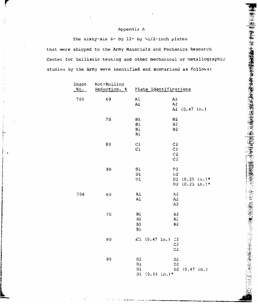
Appendix A
The sixty-six 6- by 12- by 'V1/2-inch plates k
that were shipped to the Army Materials and Mechanics Research
Center for ballistic testing and other mechanical or metallographicz
studies by the Army were identified and summarized as follous:
Ingot Hot-RollingNo. Reduction, % Plate identifications
705 60 Al A2Al A2
A2 (0.47 in.)
70 BI B2Bi B2
BI B
80 C1 C2Cl C2
C2C2__
90 Dl D2Dl U 2Dl D2 (0.25 in.)*
D2 (0.25 in.)*
706 60 Al A2Al A2
A2 4
70 Bl B2Bl B2Bl B2I Bl
80 C 1 (0.47 in.) Z2C2C2
90 Dl D2 4
Dl D2Dl D2 (0.47 in.) ADl 10.25 in.)*

Ingot Hot-RollingNo. Reduction, % Plate Identifications
717 70 B2
so ClCi C2 (0.47 in.)C1
90 D1 D2Dl D2
Dl D2Dl D2Dl D2 (C.25 in.)*Dl D2 (0.25 in.)*
4, *Plates ground tu 1/4 inch thickness by
special request of AMMRC.
Notes to Identification Codes: The letters A, B, C, and D indicate
the rolling reductions. These letters also indicate the relative
locations of the ingot, D being the bottom portion of the ingot. The
numbers 1 and 2 indicate the two halves of the ingot after preliminaryIT.,
41) rolling to intcrxediate thicknesses and cutting longitudinally along
the centerline of the slab width. Individual plates from the same
heat and the same rolling reduction are not distinguished among them-
selves otherwise.
These 66 plates plus Ii plates ballistically tested at the
U. S. Steel Research Laboratory make a total of 77 plates produced
X under the present contract. The 11 plates used for ballistic testiiiqh
at U. S. Steel consisted of one plate for each rolling reduction from
each of the tree ingots, except that no plate was made by rolling
to 60 percent reduction from the third ingot (No. 717).
A-2L _ A-

F
DISTRIBUTION LIST
No. ofCopies To
1 Office of the I)irector, Defense Research and Engineering, The Pentagon,Washington, 1. C. 20301
12 Commander, Defense Documentation Center, Cameron Station, Building 5,5010 Duke Street, Alexandria, Virginia 22314
1 Metals and Ceramics Information Center, Battelle Columbus Laboratories,SOS King Avenue, Columbus, Ohio 43201
Chief of Research and Development, Department of the Army,Washington, D. C. 2C310
2 ATTN: Physical and Engineering Sciences Division
Commander, Army Research Office, P. 0. Box 12211, ResearchTriangle Park, North Carolina 27709
I ATTN: Information Processing Office
Commander, U. S. Army Materiel Development and Readiness Command,5001 Eisenhower Avenue, Alexandria, Virginia 22333
1 ATTN: DRCLDC, Mr. R. Tentner
Commander, U. S. Army Electronics Command, Fort Monmouth, New Jersey 077031 ATTN: DRSEL-GG-I)DI 1)RSEI.-GG-I)M
Commander, U. S. Army Missile Command, Redstone Arsenal, Alabama 35809I ATTN: Technical Library1 DRSMI-RSM, Mr. F. J. Wheelahan
Commander, U. S. Army Armament Command, Rock Island, Illinois 612012 ATTN: Fechnical LibraryI DRSAR-PPW-PB, Mr. Francis X. Walter
Commander, II. S. Army Natick Research and Development Command,Natick, Massachusetts 01760
1 ATTN: Technical Library
Commanae,-, U. S. Army Satellite Comminications Agency,Fort Monmouth, New Jersey 07703
I ATTN: Technical Document Center
Commander, U. S. Army Lank-Automotive Research and Development Command,Warren, Michigan A8090
2 ATTN: DRDTA, Research Library Branch
Commander, White Sands Missile Range, New Mexico 880021 ATTN: STLWS-WS-VT

No. ofCopies To
Commander, Aberdeen Proving Ground, Maryland 210051 ATTN: STEAP-TL, Bldg. 305
Commander, Dugway Proving Ground, Dugway, Utah 840221 ATTN: Technical Library, technical Information Division
Commander, Edgewood Arsenal, Aberdeen Proving Ground, Maryland 210101 ATTN: Mr. F. F. Thompson, Dir. of Eng. 5 Ind. Serv., Chem-Mun Br
Commander, Frankford Arsenal, Philadelphia, Pennsylvania 191371 ATTN: library, 111300, Bi. 51-21 SARFA-L300, Mr. J. Corrie
Commander, larry Diamond Laboratories, 2800 Powder 1ill Road,Adelphi, Maryland 20783
1 ATTN: Technical Information Office
Commander, Picatinny Arsenal, Dover, New Jersey 078011 ATTN: SARPA-RT-S
Commander, Redstone Scientific Information Center, U. S. Army MissileCommand, Redsto.e Arsenal, Alabama 35809
4 ATTN: DRSMI-RBLD, Document Section
Cotiurander, W;,tervliet Arsenal, Water'liet, New York 121891 ATTN: SARWA-RT, Technical Information Services Office
Lomnander, U. S. Army Foreign Science and Technology Center,.0 7th Street, N. F., Charlottesville, Virginia 22901
I A FTN: DRXST- 8[52
l'irector, IlAstis Directorate, tL. F. Army Air Mobil'ty Research andDevelopment Laboratory, Fort Lustis, Virginia 23604
1 AiTN: Mi. .1. Robinson, SAVI)I-EII-SS
Librarian, Ui. S. Arrmy Aviation School Library, Fort Rucker, Alabama 313661 ATTN: Building 5907
Commander, U. S. Army Environmental HygiLne Agency, Edgewood Arsenal,Maryland 21010
1 ATTN: Chief, Library Branch
Commandant, 1J. S. Arimy Quartermaster School, Fort Lee, Virginia 238011 ATTN: Quartermaster School library
Naval Research Laboratory, Washington, I). C. 203751 ATTN: Dr. J. M. Krafft - Code 8-1302 Dr. G. R. Yoder- Code 6382

No. ofCopies To
Chief of Naval Research, Arlington, Virginia 222171 ATTN : Code 471
Air Force Materials Laboratory, Wright-Patterson Air Force Base, Ohio 454332 ATTN: AFML/MXE/E. Morrissey1 AFNIL/LCI AFML/LLP/D. M. Forney, Jr.1 AFML/MBC/Mr. Stanley Schulman
National Aeronautics and Space Administration, Washington, D. C. 205416I ATTN: Mr. B. G. Achhainner1 Mr. G. C. Deutsch - Code RR-l
National Aeronautics and Space Administration, Marshal] Space FlightCenter, Huntsville, Alabima 35812
1 ATTN: R-P&VE-M, R. J. Schwingharner1 S&E-ME-MM', Mr. W. A. Wilson, Building 4720
1 Ship Research Committee, Maritime Transportation Research Board, NationalLResearch Council, 2101 Constitution Avc. , N. W., Washington, !!. C. 20418
1 Materials Sciences Corporation, Blue bell Caiapus, Merion Towlc Buil ding,Blue Bell, Pennsylvania 19422
Wyman-Gordon Company, Worcester, Massachusetts 016011 ATTN: Technical Library
Lockheed-Georgia Company, Marietta, Georgia 300631 AITN. Advanced Composites Information Center, Dept. 72-34 --ohne 26
General Dynamics, Corvair Aerospace Division, P.O. Box 748,Fort Worth, Texas 76101
I ATTN: Mfg. Engineering Technical Library
1 Mechanical Properties Data Center, Belfour Stulei Inc.,
13917 W. Bay Shore Drive, Traverse City, Missouri 496841
Director, Army Materials and Mechanics Research Center,Watertown, Mkassachusetts 02172
2 ATTN: [RXMR-PLI DRXMR*-API DRXMIR-X1 DRYXR-XP
I 1)RXktR-l'3U D1%XMR-i.M
.\uth.)r

SE<CuRITY CL &SSI F% CAT
ION 7)" TH-S PAGE '7i. bete Entered)
NREPORT DOCUMAENTATION PAGE BFRE comNSTiNG FlonI REPORT NUMBER 12. GOVT ACCESSION IND. 3. RIECIIPIIENT'S CATALOG NUMBER .
AMMRC CTR 77-194 TITLE food S~brttI,t 5 TYPE OF REPORT A PERIOD COVERED
STUDIES OF TEXTURE DEVELOPMENT IN Final ReportSTEELARMORPLATE1/20/77 - 6/20/77
I. PERFORMING ORG. REPORT NUMBERt
7 AU~io~ra,76-H-037 \
7. AUTOR~s; CONTRACT OR GRANT NUMBER(*)
k lsun Hu DAAG4-77-C-0014 r'-
0 PERFOR4MING ORGANIZATION N4AME AND ADDRESS 13. PROGRAM ELEMENT, PROJECT. TASKAREA A WORK JNIT NUMBERS
I/A Proj. 1T162105AH84jLMS Codd&-1.Q5..1.H840jgency Accession:
11 CNTOIINCi OrFICE NAME AND ADDRESS t_ 12 REPORT DATE
Army Materials and Mechanics Research _____________
Center, Wattertown, Massachusetts 0217214 MONITORIN . AGEN4CY NAME & AOORESS(II different from Controlling ot..) 15 SECURITY CLASS. (ol ill&1 report)
IS. DECLASSIFICATION DOWNGRADING
16 DISTRIBUTION STATEMENT fol tisl Report)
Approved for public release; distribution unlimited.
17. DISTRIBUTION STATEMENT
lot the abstrted Wnt.df In, #lock 20. It d ltt.,nt frog" Ropect)
III SUPPLEMENTARY NOTES
19 KEY WORDS (Coninue* ont reverse side If necowe.m winE identity by block numsber)
Arxmor Mechanical propertiesSteel armor BallisticsArmor plate TextureAustenite
20 ABSTRACT (Continue on reverse side It n.e.y .d Identify by block numnber)
The present research program consisted of two parts. (1) To pro-duce a nunber of 6- by 12- by I,1/2-inch armor plates having strong(112) + (111) texture with various degrees of intensity by thetheirnomechanical processing treatments of essentially the samemedium-carbon, 5Ni-Si-Cu-Mo-V steels used previously, and to establish the reproducibility of texture, microstructure, hardness, andballistic performance of these steel armor plates. Results
DD ro~ 1473 EC-vION o, NOI -- v S, OCIOLETN *I.1o- 146601 UNCLASMSIZIED2
SECURITY CLASSIFICATION OF THIS WAGE ftfifl ete EtnI4,Fd)

rIUNCLASSIFIED
indicated that the reproducibility of the structure and propertiesof these steel armor plates was excellent. The ballistic limitincreased with the texture intensity in nearly the same manner asobserved previously. (2) To explore the possibility of producinga nearly (111) texture with various4egrees of intensity in small-size specimens cross-rolled at 1500 F to various reductions thenquenched, and to establish a procedure for optimizing this texturein larger 6- by 12- by '4/2-inch plates. ABsults indicated thatthe texture obtained was (223}<032), which is about 13 degrees from1lll) (011), close to that predicted. The development of thistexture should be possible in larger 6- by 12- by-i/2-inch platesthat can be used for the testing of mechanical and ballisticproperties.
SECURITY C6.ASSIPICATION 00 THIS PAQ[VIN Da 8nr...

5; a5
iA t
x. I '
II Z
- - - - - - - -F --
F~~~~~ 4i.-- S S- -

r]
ii
I I--.---..tc-
.-. ;,,'.-. .. o:, ti c..
L. 5-~"!
~ L I5.I


