CM1N4566E05.2003
for valves with a 20 mm or 40 mm stroke
!!! !!!" "
• !!! !!!# $%& '(")*"') ""!!!*"""Ω'+%,
• !!!"# !!! '-+%,• !!! .# !!! '-./%%&• !!! .# !!! .'-+,0,,
%'1'2+3-%%',%,,%'%45 *!!!45*!!!6
• , 7""8• ,,+#2%• ,-1• 1-• /(• $&• 93%• 5&&:32• ,+;+'
1&0!!!6• !!! .!!! ../%%&
For latest prices and delivery to your door visit MyTub Ltd - 0845 303 8383 - www.mytub.co.uk - [email protected]
2/14
Siemens Building Technologies Electro-hydraulic actuators CM1N4566EHVAC Products 05.2003
%%
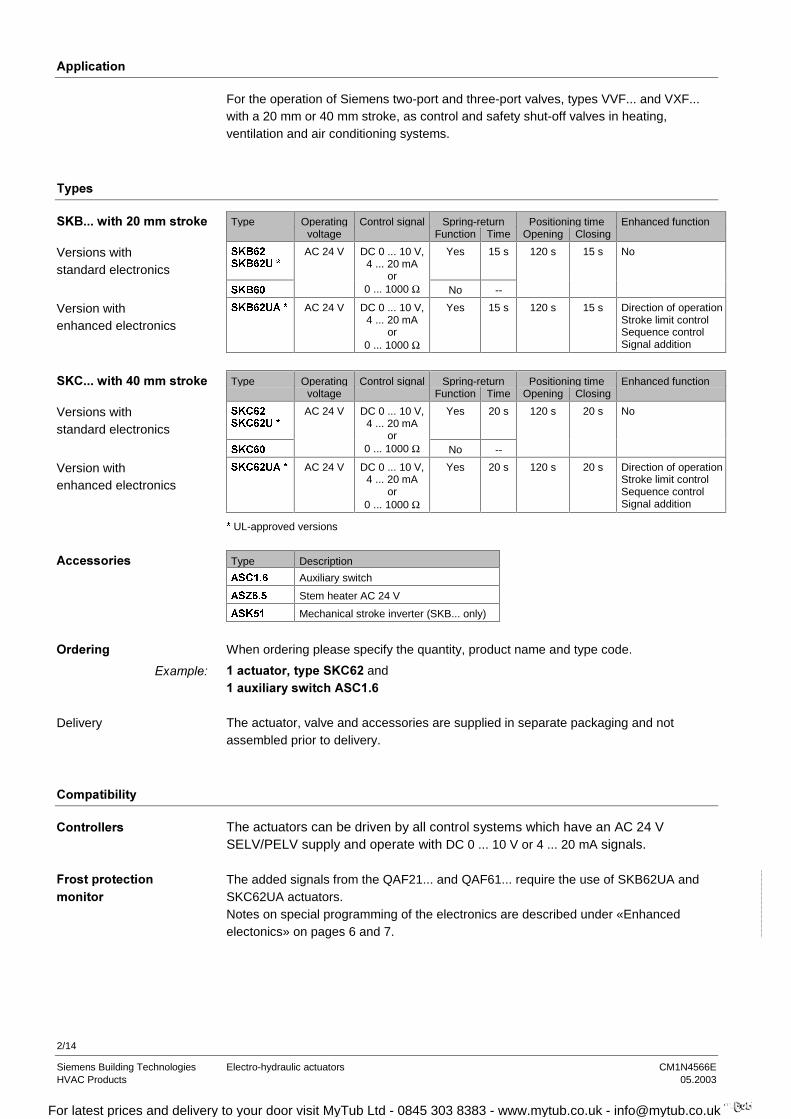
For the operation of Siemens two-port and three-port valves, types VVF... and VXF...with a 20 mm or 40 mm stroke, as control and safety shut-off valves in heating,ventilation and air conditioning systems.
%
Type Operating Control signal Spring-return Positioning time Enhanced functionvoltage Function Time Opening Closing
6.%6.%8
Yes 15 s 120 s 15 s No
6.%
AC 24 V DC 0 ... 10 V,4 ... 20 mA
or0 ... 1000 Ω No --
6.%8$ AC 24 V DC 0 ... 10 V,4 ... 20 mA
or0 ... 1000 Ω
Yes 15 s 120 s 15 s Direction of operationStroke limit controlSequence controlSignal addition
Type Operating Control signal Spring-return Positioning time Enhanced functionvoltage Function Time Opening Closing
6.&6.&8
Yes 20 s 120 s 20 s No
6.&
AC 24 V DC 0 ... 10 V,4 ... 20 mA
or0 ... 1000 Ω No --
6.&8$ AC 24 V DC 0 ... 10 V,4 ... 20 mA
or0 ... 1000 Ω
Yes 20 s 120 s 20 s Direction of operationStroke limit controlSequence controlSignal addition
UL-approved versions
Type Description
$6& Auxiliary switch
$6= Stem heater AC 24 V
$6. Mechanical stroke inverter (SKB... only)
When ordering please specify the quantity, product name and type code.
*'% and*;+*!
The actuator, valve and accessories are supplied in separate packaging and notassembled prior to delivery.
%-
The actuators can be driven by all control systems which have an AC 24 VSELV/PELV supply and operate with DC 0 ... 10 V or 4 ... 20 mA signals.
The added signals from the QAF21... and QAF61... require the use of SKB62UA andSKC62UA actuators.Notes on special programming of the electronics are described under «Enhancedelectonics» on pages 6 and 7.
!!!+ "1
Versions withstandard electronics
Version withenhanced electronics
!!!+"1
Versions withstandard electronics
Version withenhanced electronics
$
Delivery
5%
For latest prices and delivery to your door visit MyTub Ltd - 0845 303 8383 - www.mytub.co.uk - [email protected]

3/14
Siemens Building Technologies Electro-hydraulic actuators CM1N4566EHVAC Products 05.2003
The actuators are suitable for operation of the following Siemens two-port andthree-port valves with a 20 mm or 40 mm stroke:
Valve DN PN Data sheet
7ZRSRUWYDOYHV99«FRQWUROYDOYHVRUVDIHW\VKXWRIIYDOYHV
99)(Flange) 25 ... 100 6 4310
99)(Flange) 25 ... 150 10 4320
99)(Flange) 15 ... 150 16 4330
99)(Flange) 50 ... 150 16 4340
99)(Flange) 50 ... 150 16 4345
99)(Flange) 15 ... 40 25 4373
99)(Flange) 15 ... 150 40 4382
7KUHHSRUWYDOYHV9;FRQWUROYDOYHVIRUPL[LQJDQGGLVWULEXWLRQ
9;)(Flange) 25 ... 100 6 4410
9;)(Flange) 25 ... 150 10 4420
9;)(Flange) 15 ... 150 16 4430
9;)(Flange) 15 ... 150 16 4440
9;)(Flange) 15 ... 150 40 4482
For admissible differential pressures ∆pmax and closing pressures ∆ps, refer to the relevantvalve data sheets.
Third-party valves with strokes between 6 and 20 mm (SKB...) and 12 ... 40 mm(SKC...) can be motorized, provided they have a «closed when de-energized» failsafemechanism, and provided that the necessary mechanical coupling is available.We recommend that you contact your local Siemens office for the necessaryinformation.
Manual adjuster
Pressure cylinder
Piston
Reservoir
Pressure chamber
Pump
Return spring
Bypass valve
Coupling
Valve stem
Inner valve
Position indicator (0 to 1)
Valve closed Valve open
%<
• =# The pump () forces hydraulic oil from the reservoir () into thepressure chamber () thereby generating the stroke: the valve stem() is retracted and the valve plug opens ().
• (# The bypass valve () opens, allowing the hydraulic oil to flow backfrom the pressure chamber () into the reservoir () via the returnspring (). The valve stem () extends and the valve plug closes ().
• # The actuator and valve hold the current stroke position.
>-&&
Note
%,%
For latest prices and delivery to your door visit MyTub Ltd - 0845 303 8383 - www.mytub.co.uk - [email protected]
4/14
Siemens Building Technologies Electro-hydraulic actuators CM1N4566EHVAC Products 05.2003
8
=
<
0
*
*
3RZHUVXSSO\
6HWWLQJVDQGLQGLFDWRUV
8VHULQWHUIDFH
Inputoverride(Signal priority)
InputValve SeatDetection
Valve JamDetection
DC 0 ...10 Vor
4 ... 20 mA
DC 0 ...10 Vor
4 ... 20 mA
– G
– G0
– 0 ...1000 Ω
Stroke
Fully open
0 ...100 %
Fully closed
0 ...100 %Stroke
Pump
Solenoid
Stroke
Valve
01706en
Output
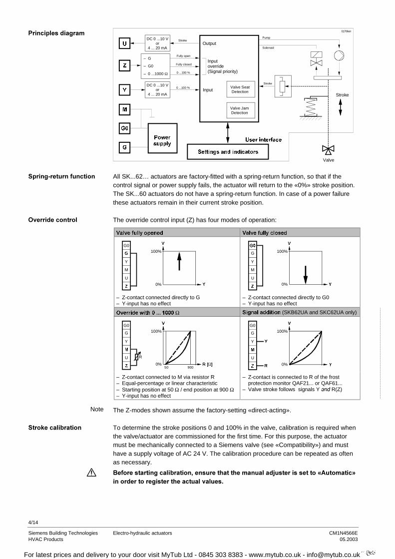
All SK...62… actuators are factory-fitted with a spring-return function, so that if thecontrol signal or power supply fails, the actuator will return to the «0%» stroke position.The SK...60 actuators do not have a spring-return function. In case of a power failurethese actuators remain in their current stroke position.
The override control input (Z) has four modes of operation:
9DOYHIXOO\RSHQHG 9DOYHIXOO\FORVHG
U
=
G0
*
Y
M
100%
<0%
9
U
=
*
G
Y
M
100%
<0%
9
– Z-contact connected directly to G– Y-input has no effect
– Z-contact connected directly to G0– Y-input has no effect
2YHUULGHZLWKΩ 6LJQDODGGLWLRQ(SKB62UA and SKC62UA only)
U
=
G0
G
Y
0
R
100%
5>Ω@0%50 900
9
U
=
G0
G
Y
0
5
<
100%
<0%
9
– Z-contact connected to M via resistor R– Equal-percentage or linear characteristic– Starting position at 50 Ω / end position at 900 Ω– Y-input has no effect
– Z-contact is connected to R of the frost protection monitor QAF21... or QAF61...
– Valve stroke follows signals Y DQG R(Z)
The Z-modes shown assume the factory-setting «direct-acting».
To determine the stroke positions 0 and 100% in the valve, calibration is required whenthe valve/actuator are commissioned for the first time. For this purpose, the actuatormust be mechanically connected to a Siemens valve (see «Compatibility») and musthave a supply voltage of AC 24 V. The calibration procedure can be repeated as oftenas necessary.
,-'3?@&!
%
%,
$&
Note
1-
For latest prices and delivery to your door visit MyTub Ltd - 0845 303 8383 - www.mytub.co.uk - [email protected]
5/14
Siemens Building Technologies Electro-hydraulic actuators CM1N4566EHVAC Products 05.2003
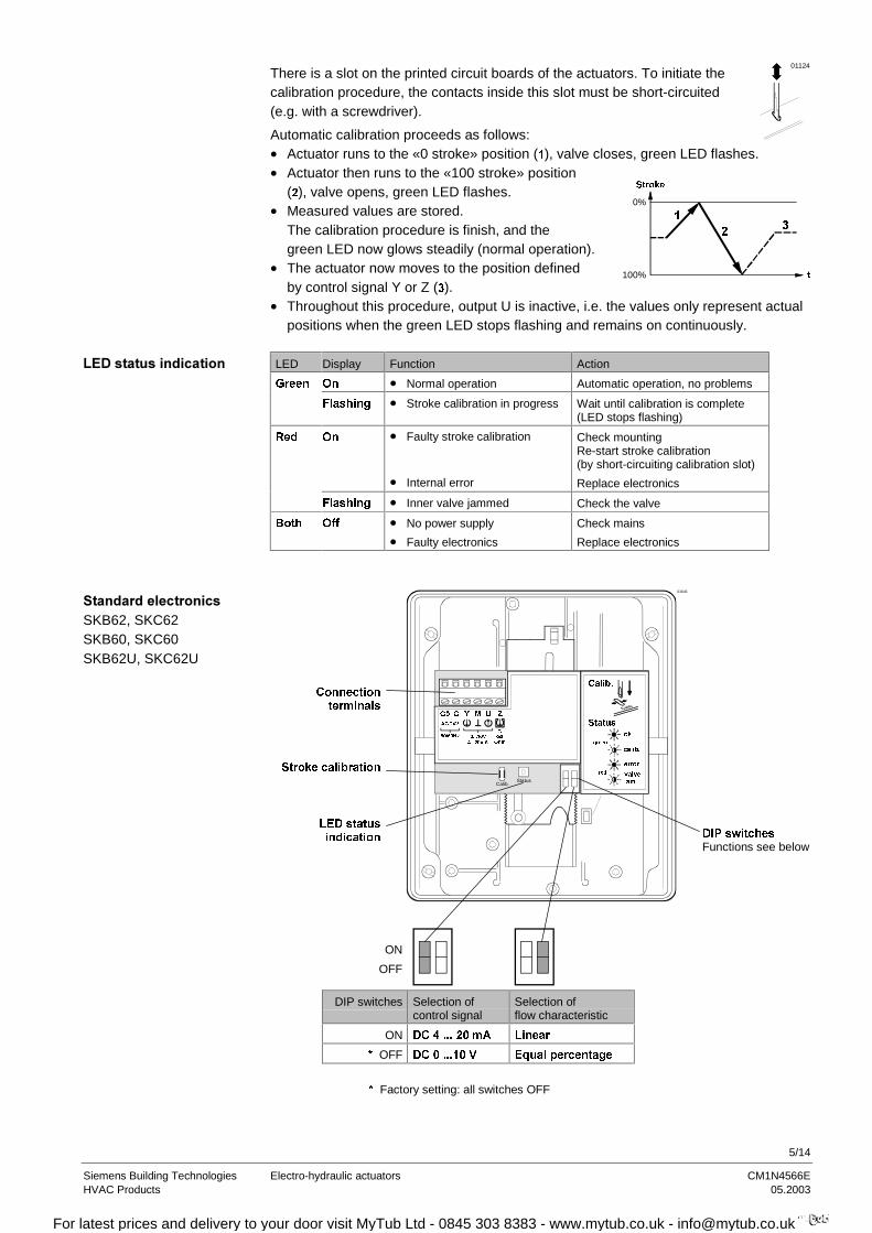
There is a slot on the printed circuit boards of the actuators. To initiate thecalibration procedure, the contacts inside this slot must be short-circuited(e.g. with a screwdriver).
Automatic calibration proceeds as follows:
01124
• Actuator runs to the «0 stroke» position (), valve closes, green LED flashes.• Actuator then runs to the «100 stroke» position
(), valve opens, green LED flashes.• Measured values are stored.
The calibration procedure is finish, and thegreen LED now glows steadily (normal operation).
• The actuator now moves to the position definedby control signal Y or Z ().
0%
W100%
6WURNH
• Throughout this procedure, output U is inactive, i.e. the values only represent actualpositions when the green LED stops flashing and remains on continuously.
LED Display Function Action
*UHHQ 2Q • Normal operation Automatic operation, no problems
)ODVKLQJ • Stroke calibration in progress Wait until calibration is complete(LED stops flashing)
5HG 2Q • Faulty stroke calibration
• Internal error
Check mountingRe-start stroke calibration(by short-circuiting calibration slot)
Replace electronics
)ODVKLQJ • Inner valve jammed Check the valve
%RWK 2II • No power supply
• Faulty electronics
Check mains
Replace electronics
&RQQHFWLRQWHUPLQDOV
6WURNHFDOLEUDWLRQ
/('VWDWXVLQGLFDWLRQ
01643
Calib.Status
RN
FDOLE
HUURU
YDOYH
MDP
JUHHQ
UHG
6WDWXV
&DOLE
9P$ 2KP
=80<**
$&9
+]**
',3VZLWFKHVFunctions see below
ON
OFF
DIP switches Selection ofcontrol signal
Selection offlow characteristic
ON '&P$ /LQHDU
OFF '&9 (TXDOSHUFHQWDJH
Factory setting: all switches OFF
/(
SKB62, SKC62SKB60, SKC60SKB62U, SKC62U
For latest prices and delivery to your door visit MyTub Ltd - 0845 303 8383 - www.mytub.co.uk - [email protected]
6/14
Siemens Building Technologies Electro-hydraulic actuators CM1N4566EHVAC Products 05.2003
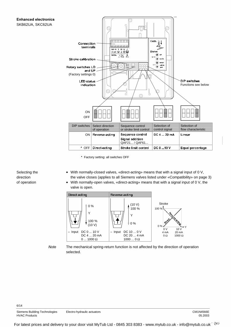
&RQQHFWLRQWHUPLQDOV
6WURNHFDOLEUDWLRQ
5RWDU\VZLWFKHV/2DQG83
(Factory settings 0)
/('VWDWXVLQGLFDWLRQ
01638
Calib.Status
9P$ 2KP
=80<**
$&9
+]** RN
FDOLE
HUURU
YDOYH
MDP
JUHHQ
UHG
6WDWXV
&DOLE
',3VZLWFKHVFunctions see below
ON
OFF
DIP switches Select directionof operation
Sequence controlor stroke limit control
Selection ofcontrol signal
Selection offlow characteristic
ON 5HYHUVHDFWLQJ 6HTXHQFHFRQWURO
6LJQDODGGLWLRQQAF21... / QAF61...
'&P$ /LQHDU
OFF 'LUHFWDFWLQJ 6WURNHOLPLWFRQWURO '&9 (TXDOSHUFHQWDJH
Factory setting: all switches OFF
• With normally-closed valves, «direct-acting» means that with a signal input of 0 V,the valve closes (applies to all Siemens valves listed under «Compatibility» on page 3)
• With normally-open valves, «direct-acting» means that with a signal input of 0 V, thevalve is open.
'LUHFWDFWLQJ 5HYHUVHDFWLQJ
(10 V)100 %
0 %
Y
(10 V)100 %
0 %
Y
– Input DC 0 ... 10 VDC 4 ... 20 mA0 ... 1000 Ω
– Input DC 10 ... 0 VDC 20 ... 4 mA1000 ... 0 Ω
100 %
Y
Stroke
0 %'LUHFW
5HYHUVHDFWLQJ
0 V4 mA0 Ω
10 V20 mA1000 Ω
The mechanical spring-return function is not affected by the direction of operationselected.
SKB62UA, SKC62UA
Selecting thedirectionof operation
For latest prices and delivery to your door visit MyTub Ltd - 0845 303 8383 - www.mytub.co.uk - [email protected]

7/14
Siemens Building Technologies Electro-hydraulic actuators CM1N4566EHVAC Products 05.2003
6HWWLQJWKHVWURNHOLPLWFRQWURO 6HWWLQJWKHVHTXHQFHFRQWURO
The rotary switches LO and UP can be usedto apply an upper and lower limit to the strokein increments of 3%, up to a maximum of 45%
The rotary switches LO and UP can be usedto determine the starting point or the operatingrange of a sequence.
/2
83
100 %
y
100 %
y
/2
9
83
9
3RVLWLRQRI/2
/RZHUVWURNHOLPLW
3RVLWLRQRI83
8SSHUVWURNHOLPLW
3RVLWLRQRI/2
6WDUWLQJSRLQWIRUVHTXHQFHFRQWURO
3RVLWLRQRI83
2SHUDWLQJUDQJHRIVHTXHQFH
FRQWURO
0 % 100 % 0 V 10 V 3 % 97 % 1 V 10 V
6 % 94 % 2 V 10 V
9 % 91 % 3 V 3 V
12 % 88 % 4 V 4 V 15 % 85 % 5 V 5 V 18 % 82 % 6 V 6 V 21 % 79 % 7 V 7 V 24 % 76 % 8 V 8 V 27 % 73 % 9 V 9 V$ 30 % $ 70 % $ 10 V $ 10 V% 33 % % 67 % % 11 V % 11 V& 36 % & 64 % & 12 V & 12 V' 39 % ' 61 % ' 13 V ' 13 V( 42 % ( 58 % ( 14 V ( 14 V) 45 % ) 55 % ) 15 V ) 15 V
Operating range of QAF21... (see below) Operating range of QAF61... (see below) The smallest adjustment is 3 V;
control with 0…30 V is only possible via Y.
6HWWLQJWKHVLJQDODGGLWLRQ
The operating range of the frost protectionmonitor (QAF21... or QAF61...) can be definedwith rotary switches LO and UP.3RVLWLRQRI/2
6HTXHQFHFRQWUROVWDUWSRLQW
3RVLWLRQRI83
4$)4$)RSHUDWLQJUDQJH
4$)
4$)
$6&DX[LOLDU\VZLWFK
– Switching point 0 … 5 % stroke
5 4 3
456
1Z0
8
$6=VWHPKHDWHU
− For media below 0°C− Mount between
valve and actuator01825
Stroke limit controland sequence control
Stroke control withQAF21... / QAF61...signal addition
For latest prices and delivery to your door visit MyTub Ltd - 0845 303 8383 - www.mytub.co.uk - [email protected]

8/14
Siemens Building Technologies Electro-hydraulic actuators CM1N4566EHVAC Products 05.2003
The actuators must be electrically connected in accordance with local wiring regulationsand with the wiring diagram on page 12.
A2,,%%%%--&!
B!%,C"21%&&,,"D!!!− D!='2'-1&&-!+%%-!5-&-&&,!
The admissible temperatures (see «Application» and «Technical data») must be observed.
9
E"D E"D
Instructions for fitting the actuator to the valve are enclosed in the actuator packaging.The instructions for accessories are enclosed with the accessories themselves.
When commissioning the system, check the wiring and functions.
456
4Z12
456
4Z1
3
Cylinder with valve stemconnector fully retracted
Cylinder with valve stemconnector fully extended
Orientation
For latest prices and delivery to your door visit MyTub Ltd - 0845 303 8383 - www.mytub.co.uk - [email protected]
9/14
Siemens Building Technologies Electro-hydraulic actuators CM1N4566EHVAC Products 05.2003
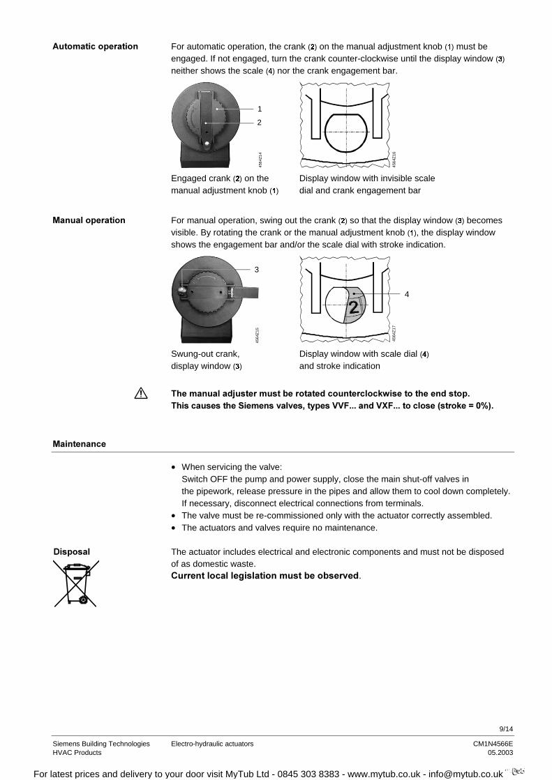
For automatic operation, the crank () on the manual adjustment knob () must beengaged. If not engaged, turn the crank counter-clockwise until the display window ()
neither shows the scale () nor the crank engagement bar.
1
2
4564
Z14
4564
Z16
Engaged crank () on themanual adjustment knob ()
Display window with invisible scaledial and crank engagement bar
For manual operation, swing out the crank () so that the display window () becomesvisible. By rotating the crank or the manual adjustment knob (), the display windowshows the engagement bar and/or the scale dial with stroke indication.
3
4564
Z15
4564
Z17
4
Swung-out crank,display window ()
Display window with scale dial ()
and stroke indication
3-1+%! &&'%5!!!F5!!!01G"H6!
9
• When servicing the valve:Switch OFF the pump and power supply, close the main shut-off valves inthe pipework, release pressure in the pipes and allow them to cool down completely.If necessary, disconnect electrical connections from terminals.
• The valve must be re-commissioned only with the actuator correctly assembled.• The actuators and valves require no maintenance.
(% The actuator includes electrical and electronic components and must not be disposedof as domestic waste.--&.
%
9%
For latest prices and delivery to your door visit MyTub Ltd - 0845 303 8383 - www.mytub.co.uk - [email protected]

10/14
Siemens Building Technologies Electro-hydraulic actuators CM1N4566EHVAC Products 05.2003
I
The application-specific technical data is valid for Siemens actuators used inconjunction with the Siemens valves listed under «Compatibility» (sub-heading «Globevalves»).
,+%&&'+%%&--, !,-%%&&!
!!! !!!
Power supply Operating voltage (SELV, PELV) AC 24 V –20 % / +30 %
Frequency 50 or 60 HzPower consumption SK...62... SK...60
17 VA / 12 W13 VA / 10 W
28 VA / 20 W24 VA / 18 W
External supply cable fuse Min. 1 A slow blow,Max. 10 A slow blow
Min. 1.6 A slow blow,Max. 10 A slow blow
Operating data Type of control (proportional) DC 0 ... 10 V, DC 4 ... 20 mAor 0 ... 1000 Ω
Positioning time at 50 Hz 120 s (opening)15 s (closing)
120 s (opening)20 s (closing)
Spring-return function to DIN 32730Spring-return time (closing) 15 s 20 sNominal stroke 20 mm 40 mmPositioning force 2800 NFlow characteristic Equal percentage / linear
can be selected Maximum admissible temperature of medium in the connected valve
−25 ... +220 °C< 0 °C: type ASZ6.5 stem heater required> 220 ... +350 °C: use special extension
on valveSignal inputs Terminal Y
Voltage Input impedance Current Input impedance Signal resolution Hysteresis
DC 0 ... 10 (30) V100 kΩDC 4 ... 20 mA240 Ω<1 % 1 %
Terminal Z Resistance 0 ... 1000 ΩOverride control functions Z not connected Z connected directly to G Z connected directly to G0 Z connected to M via 0 ... 1000 Ω
No function (priority at Terminal Y)Max. stroke 100 %Min. stroke 0 %Stroke proportional to R
Signal outputs Terminal U Voltage Load impedance Current Load impedance
DC 0 ... 9.8 V ±2 %
>500 ΩDC 4 ... 19.6 mA ±2 %
<500 Ω
in conjunction with valves listed under «Compatibility» on page 3
For latest prices and delivery to your door visit MyTub Ltd - 0845 303 8383 - www.mytub.co.uk - [email protected]
11/14
Siemens Building Technologies Electro-hydraulic actuators CM1N4566EHVAC Products 05.2003
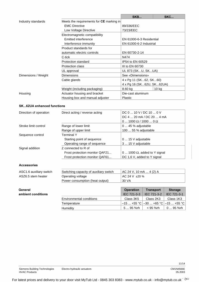
!!! !!!Industry standards Meets the requirements for marking in
EMC Directive Low Voltage Directive
89/336/EEC73/23/EEC
Electromagnetic compatibility Emitted interference Interference immunity
EN 61000-6-3 ResidentialEN 61000-6-2 Industrial
Product standards forautomatic electric controls EN 60730-2-14C-tick N474Protection standard IP54 to EN 60529Protection class III to EN 60730UL approval UL 873 (SK...U, SK...UA)
Dimensions / Weight Dimensions See «Dimensions»Cable glands 4 x Pg 11 (SK...62, SK...60)
4 x Pg 16 (SK...62U, SK...62UA)Weight (including packaging) 8.60 kg 10 kg
Housing Actuator housing and bracketHousing box and manual adjuster
Die-cast aluminumPlastic
!!! .,
Direction of operation Direct acting / reverse acting DC 0 ... 10 V / DC 10 ... 0 VDC 4 ... 20 mA / DC 20 ... 4 mA0 ... 1000 Ω / 1000 ... 0 Ω
Stroke limit control Range of lower limitRange of upper limit
0 ... 45 % adjustable100 ... 55 % adjustable
Sequence control Terminal Y Starting point of sequence Operating range of sequence
0 ... 15 V adjustable3 ... 15 V adjustable
Signal addition Z connected to R of Frost protection monitor QAF21... Frost protection monitor QAF61...
0 ... 1000 Ω, added to Y signalDC 1,6 V, added to Y signal
ASC1.6 auxiliary switch Switching capacity of auxiliary switch AC 24 V, 10 mA ... 4 (2) AASZ6.5 stem heater Operating voltage
Power consumption (heat output)AC 24 V ±20 %
30 VA
>-
$%IEC 721-3-3
%IEC 721-3-2
IEC 721-3-1
Environmental conditions Class 3K5 Class 2K3 Class 1K3Temperature –15 ... +55 °C –30 ... +65 °C –15 ... +55 °C
Humidity 5 ... 95 %rh < 95 %rh 0 ... 95 %rh
For latest prices and delivery to your door visit MyTub Ltd - 0845 303 8383 - www.mytub.co.uk - [email protected]
12/14
Siemens Building Technologies Electro-hydraulic actuators CM1N4566EHVAC Products 05.2003
G B1 M
G0 Y1
1
G M Z
G0
<Y U
B M
%
G (SP)
G0 (SN)
$&9
)
32
1
M
Fus
e)
MR
M Z <U
)
MR
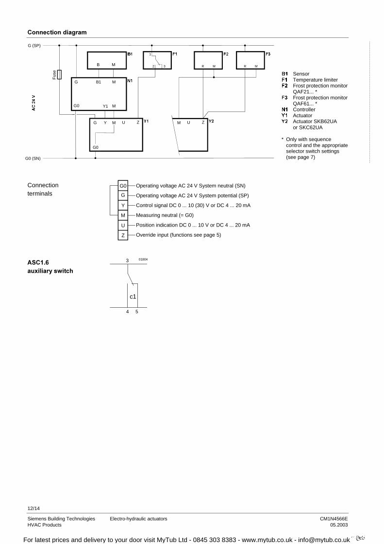
% Sensor) Temperature limiter) Frost protection monitor
QAF21... *) Frost protection monitor
QAF61... *1 Controller< Actuator< Actuator SKB62UA
or SKC62UA
* Only with sequencecontrol and the appropriateselector switch settings(see page 7)
U
Z
G0
G
Y
M
Operating voltage AC 24 V System neutral (SN)
Operating voltage AC 24 V System potential (SP)
Control signal DC 0 ... 10 (30) V or DC 4 ... 20 mA
Measuring neutral (= G0)
Position indication DC 0 ... 10 V or DC 4 ... 20 mA
Override input (functions see page 5)
c1
3
4 5
01804
Connectionterminals
*!;+
For latest prices and delivery to your door visit MyTub Ltd - 0845 303 8383 - www.mytub.co.uk - [email protected]
13/14
Siemens Building Technologies Electro-hydraulic actuators CM1N4566EHVAC Products 05.2003
(
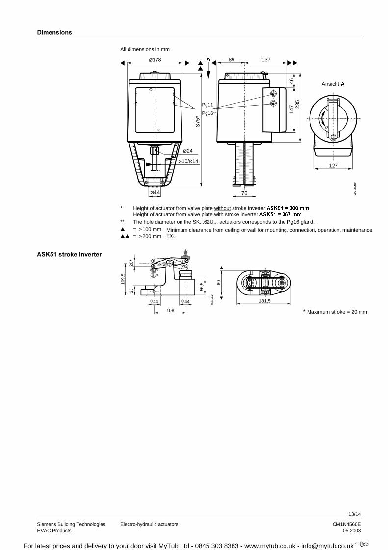
All dimensions in mm
1
0
235
Ø44 76
127
147
89 137
375*
Pg11
Pg16**
Ansicht $
$
456
4M01
Ø178
46
Ø24
Ø10/Ø14
* Height of actuator from valve plate without stroke inverter $6. PPHeight of actuator from valve plate with stroke inverter $6. PP
** The hole diameter on the SK...62U... actuators corresponds to the Pg16 gland. = >100 mm = >200 mm
Minimum clearance from ceiling or wall for mounting, connection, operation, maintenanceetc.
20*
109
,5
35
44 44
56,5
108
181,5
80
∅∅
4561
M02
* Maximum stroke = 20 mm
*1&
For latest prices and delivery to your door visit MyTub Ltd - 0845 303 8383 - www.mytub.co.uk - [email protected]

14/14
Siemens Building Technologies Electro-hydraulic actuators CM1N4566EHVAC Products 05.2003
2002 Siemens Building Technologies Ltd. Subject to alteration
For latest prices and delivery to your door visit MyTub Ltd - 0845 303 8383 - www.mytub.co.uk - [email protected]


