download manual - lincat · opus 800 electric fryers oe8112, oe8112/op, oe8114, oe8114/op, ......
TRANSCRIPT

IS 594 ECN 4269 Page 1 of 23
Installation, Operating and Servicing Instructions
Opus 800 Electric Fryers OE8112, OE8112/OP, OE8114, OE8114/OP, OE8105, OE8105/OP, OE8105/OP2, OE8108, OE8108/OP, OE8113, OE8113/OP, OE8113/OP2
Please make a note of your product details for future use: Date Purchased:_________________________ Model Number:__________________________ Serial Number:__________________________ Dealer:_________________________________ _______________________________________

IS 594 ECN 4269 Page 2 of 23
CONTENTS
Important Information 2 Warnings and Precautions 3 Technical Data 4 Checklist of Enclosures 5 Installation and Commissioning 5-8 Operating Instructions 8-10 Cleaning 11-14 Servicing, Maintenance and Component Replacement 14-19 Fault Finding 20 Spare Parts List 21 Accessories 22 Service Information and Guarantee 23
IMPORTANT INFORMATION
Read these instructions carefully before using this product, paying particular attention to all sections that carry warning symbols, caution symbols and notices. Ensure that these are understood at all times.
WARNING! This symbol is used whenever there is a risk of personal injury.
CAUTION! This symbol is used whenever there is a risk of damaging your Lincat product.
NOTE: This symbol is used to provide additional information, hints and tips.
KEEP THIS MANUAL FOR FUTURE REFERENCE

IS 594 ECN 4269 Page 3 of 23
WARNINGS AND PRECAUTIONS This appliance must be installed, commissioned and serviced by a qualified person in accordance with national and local regulations in force in the country of installation. If the supply cord is damaged, it must be replaced by the manufacturer, its service agent or similarly qualified person. Ensure that the plug/socket is accessible at all times. Strip plastic coating and clean the appliance before use. During operation parts may become hot - avoid accidental contact. Disconnect this appliance before servicing, maintenance or cleaning. This unit is designed to be used with oils and fats in a liquid form. Oils and fats that become solid at lower temperatures must be liquefied prior to dispensing into the fryer tank. This instruction includes both filling from empty and topping up during use.
On units with filtration the oil or fat used must also be liquid prior to operating the pump.

IS 594 ECN 4269 Page 4 of 23
TECHNICAL DATA
OE8112 OE8114 OE8105 OE8108 OE8113 Height to hob (mm) 900 Width (mm) 300 400 400 600 600 Depth (mm) 800 Weight (kg)* 57-61 61-65 61-69 72-77 85-93 Oil capacity (hot litres)** 15 19 2 x 9.5 36.5
2 x 15
Power Rating (kW) 12.0 14.0 14.0 22.0 24.0 Electrical supply 1N~+E One supply cable 230V 50-60Hz Current rating (A)
52.2 60.8 60.8 N/A N/A
Electrical supply 1N~+E Two supply cables 230V 50-60Hz Current rating (A)
N/A N/A N/A 2 x 47.8 2 x 52.2
Electrical supply 3N~+E One supply cable 400V 50-60Hz Current rating (A)
L1 17.5 L2 17.5 L3 17.5
L1 20.3 L2 20.3 L3 20.3
L1 20.3 L2 20.3 L3 20.3
L1 31.8 L2 31.8 L3 31.8
L1 34.8 L2 34.8 L3 34.8
Electrical supply 3N~+E Two supply cables 400V 50-60Hz Current rating (A)
N/A N/A N/A 2 x L1 15.9 2 x L2 15.9 2 x L3 15.9
2 x L1 17.4 2 x L2 17.4 2 x L3 17.4
* Weight dependent on number of pumps ** Fill appliance with cold oil to minimum level on marker plate – see Operating Instructions
OE8112 OE8114 OE8105 OE8108 OE8113 Recommended batch sizes (Kg)
1.75 1.5 1.25 1.5 1.5
IS 594 ECN 4269 Page 5 of 23
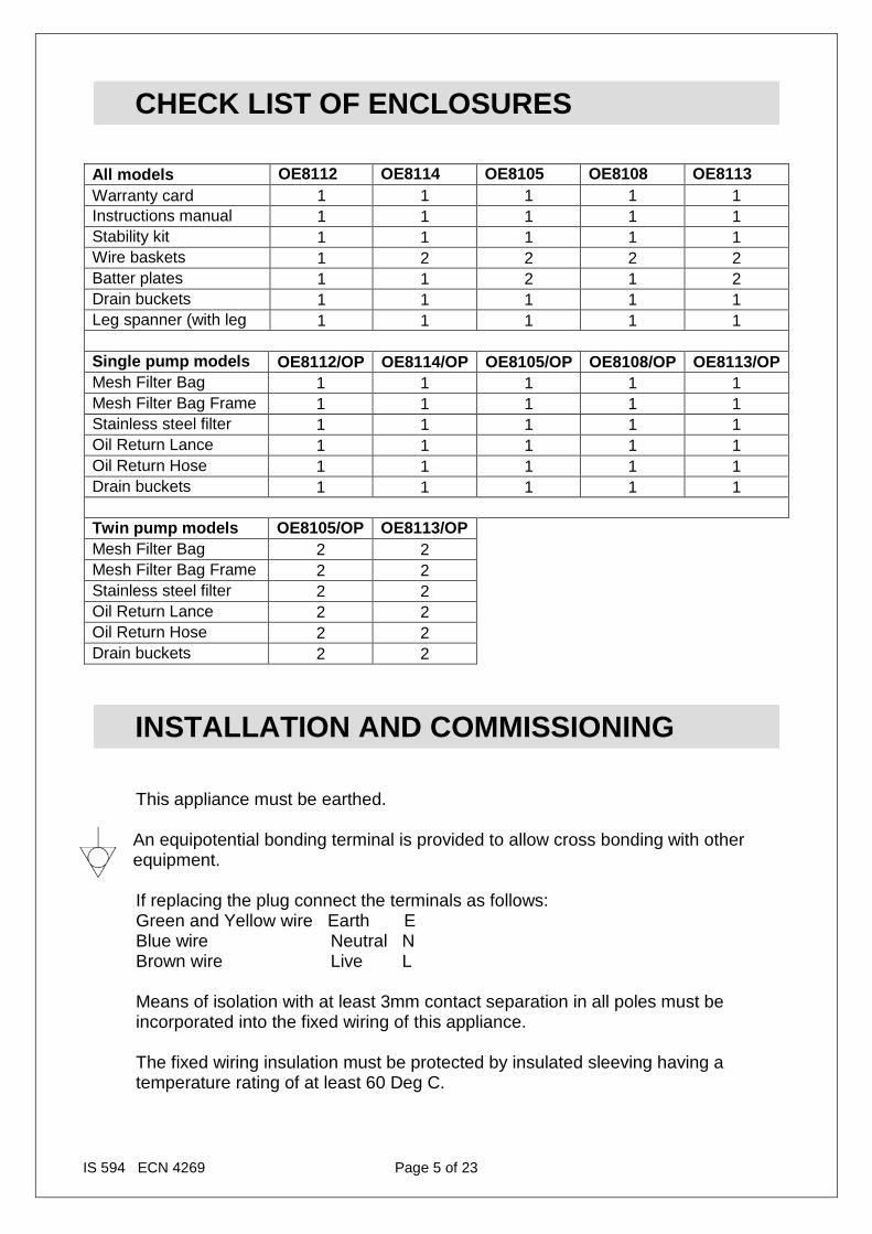
CHECK LIST OF ENCLOSURES
All models OE8112 OE8114 OE8105 OE8108 OE8113 Warranty card 1 1 1 1 1 Instructions manual 1 1 1 1 1 Stability kit 1 1 1 1 1 Wire baskets 1 2 2 2 2 Batter plates 1 1 2 1 2 Drain buckets 1 1 1 1 1 Leg spanner (with leg
1 1 1 1 1
Single pump models
OE8112/OP OE8114/OP OE8105/OP OE8108/OP OE8113/OP
Mesh Filter Bag 1 1 1 1 1 Mesh Filter Bag Frame 1 1 1 1 1 Stainless steel filter 1 1 1 1 1 Oil Return Lance 1 1 1 1 1 Oil Return Hose 1 1 1 1 1 Drain buckets 1 1 1 1 1 Twin pump models OE8105/OP
OE8113/OP Mesh Filter Bag 2 2
Mesh Filter Bag Frame 2 2 Stainless steel filter 2 2 Oil Return Lance 2 2 Oil Return Hose 2 2 Drain buckets 2 2
INSTALLATION AND COMMISSIONING
This appliance must be earthed. An equipotential bonding terminal is provided to allow cross bonding with other equipment.
If replacing the plug connect the terminals as follows: Green and Yellow wire Earth E Blue wire Neutral N Brown wire Live L
Means of isolation with at least 3mm contact separation in all poles must be incorporated into the fixed wiring of this appliance. The fixed wiring insulation must be protected by insulated sleeving having a temperature rating of at least 60 Deg C.

IS 594 ECN 4269 Page 6 of 23
Supply cords shall be oil resistant, sheathed flexible cable not lighter than ordinary polychloroprene or equivalent elastomer sheathed cord (code 60245 IEC 57) Install this appliance on a level surface ensuring all vents are unobstructed. Any partitions, walls or furniture must be of non-combustible material. Minimum distances A 100mm B 1,000mm – see Fig 1.
Fig 1 Install this appliance beneath an extraction canopy. Do not install adjacent to any appliance that has an exposed flame. If this appliance is fitted with castors, use caution at all times when manipulating or moving, and lock castors when appliance is in position. Do not move the appliance when the tank contains oil. Danger of fire exists if oil is not kept to the minimum level.

IS 594 ECN 4269 Page 7 of 23
Fitting the Stabilising Kit (Fig 2) The stabilising kit must be fitted to prevent accidental toppling of the appliance and to ensure a safe working environment. Fit the adjustable stabiliser centrally to the underside of the front cross member of the appliance (A) using the M5 x 16 hex screws and shake proof washers provided. Ensure the tongue of the bracket is facing rearward and adjusted to sit just off the floor(C). Position the appliance in the intended place. Place the floor plate (D) on the floor so that it fits over the tongue of the stabiliser. Mark locating hole positions of the floor plate. Drill out holes and fit supplied rawlplugs. Screw the floor plate in position using 12g screws. Adjust height position (B) of stabiliser tongue if necessary.
Fig 2
Electrical supply and connection Remove the rear panel to gain access to connections. If connecting OE8113 or OE8108 appliances to two mains supplies, remove link wires between terminal blocks.

IS 594 ECN 4269 Page 8 of 23
The appliance is fitted with a safety cutout switch on the element mounting that disconnects the supply to the element when it is raised in the cleaning position. Commissioning Ensure that the drain taps are closed and clean the tanks thoroughly with a warm, mild detergent solution. Rinse the tanks, tap and drain pipe and dry thoroughly. Close the drain valve. Run a small quantity of oil across the surfaces of the tanks. Re-open the drain tap to allow this to drain through and remove any traces of water. Close the drain taps and fill the tank with clean oil to the minimum marker. With the control in the ‘Off’ position, switch the appliance on at the isolator – the green neon will illuminate. Turn the control knob to the required temperature – the corresponding amber neon will illuminate. The amber neon will extinguish when the temperature is reached, and operate intermittently as the element cycles. Operationally check the appliance by setting the thermostat to 190ºC and allowing the fryer to cycle a few times. Check the temperature of the oil at the geometric centre of the tank 25mm below the surface. Ensure that the end user understands how to operate, shutdown and clean the appliance, and is aware of the position of the isolating switch.
OPERATING INSTRUCTIONS
Only qualified or trained personnel should use this appliance. General advice
Always drain product before frying. Ensure water is never introduced into the oil as this will cause splashing and possible overflow from the tank.
Do not operate the fryer with the dust cover in place. Do not leave the appliance unattended whilst operating.
Keep the oil level maintained to the minimum marker. Do not overfill with oil as it may then exceed the capacity of the drain tank.

IS 594 ECN 4269 Page 9 of 23
AB C
D
E
F
G
H
I
For maximum efficiency, do not overload the baskets with product as it will result in reduced recovery times, uneven cooking and increased risk of surge boiling. (See Technical Data for recommended batch sizes).
Oil should be filtered regularly. Old oil has a reduced flashpoint and is more prone to surge boiling. Controls and parts identification
Fig 3 A Pump drain connector B Knurled knob C Splash cover D Control knob E Amber neon F Green neon G Pump/Element switch H Drain lever I Drain bucket

IS 594 ECN 4269 Page 10 of 23
J
Operation Check that the drain tap levers are closed and locked. Fill the tank to the minimum marker, which is on the capillary covers at the back of the tank. Ensure that the control knob is turned to the ‘Off’ position. Turn on the power supply at the isolating switch. The green neon indicates power to the appliance. Turn the control knob to the required temperature setting. The amber neon illuminates to indicate the operation of the element. When the amber neon extinguishes, temperature is reached and cooking may begin. The amber neon will cycle as the element operates to maintain oil temperature. Shutdown To shut the appliance down, turn the control knobs to the ‘Off’ position. Turn off the power at the isolating switch. Draining the oil See Cleaning Instructions section Safety thermostat Should the appliance fail to operate, the safety thermostat may need resetting. This is a red button protruding through the floor of the control panel. To access the safety thermostat, open the door and it may be found in the top left hand corner of the cabinet. The appliance must be allowed to cool down before the safety thermostat can be reset. Should the appliance still fail to operate, consult a qualified engineer.
Fig 4 J Safety cut-out location (N.B. more central on OE8112)

IS 594 ECN 4269 Page 11 of 23
CLEANING
Your product has a manufacturer’s warranty. This requires you maintain and care for your product and follow maintenance instructions. If you fail to maintain your unit or damage components Lincat may charge you for a warranty repair. Please check the website for terms and conditions.
The appliance must be disconnected from the mains before cleaning begins.
Do not use a water jet or steam cleaner, and do not immerse this appliance.
Clean all outer panels with warm water and mild detergent, do not use abrasive materials. Dry with a soft cloth.
Draining the oil
Please note that although the drain buckets are capable of taking the full volume of the tanks, Lincat strongly recommend draining only the amount of oil that can be comfortably lifted and manually handled at any one time. For gravity appliances Allow the oil to cool to at least 55ºC. If the filtration kit has been purchased, ensure this is correctly located. Ensure the oil drain bucket is empty and pushed all the way back so that the bucket is correctly located beneath the outlet pipe beneath the tank. Open the tap by holding the sprung lever to the right and turning the red drain handle anti-clockwise. Allow the oil to drain into the bucket. Return the drain tap to the closed position. Either dispose of the oil or filter before returning it to the tank. For pumped appliances (Fig 5)
Caution: When full of hot oil, the outer surfaces of the drain tank will become hot. Ensure that the filtration frame, mesh filtration bag, steel filter and the suction pipe are correctly fitted and secured in the oil bucket and that the bucket is pushed fully back so that it is engaged in the pump connection. Drain the oil and close the drain valve as previously explained. Securely connect the oil return lance into the connector outlet over the desired tank.
IS 594 ECN 4269 Page 12 of 23
Operate the pump run switch until the oil has returned to the fryer tank then turn off the pump run switch. Remove the oil return lance, clean and place back in the door bracket. To drain oil into separate container Repeat the above procedure, but connect the return hose into the connector instead of the oil return lance.
K
L M
N
O
Fig 5
K Mesh filter bag L Mesh filter frame M Stainless steel filter N Pump connection O Oil return lance Cleaning tanks (Fig 6,7) Food debris can be a health risk – ensure the tanks are cleaned thoroughly after use. N.B. The elements can be raised from the tanks to allow easy access for cleaning. As the elements are raised to the parking position, a safety switch disconnects the power supply. The power is re-connected when the elements are returned to the operating position. This is an additional safeguard – the appliance must be isolated from the supply before cleaning. Remove the batter plate.

IS 594 ECN 4269 Page 13 of 23
PQ
R
S
Undo the knurled nuts and lift the splash cover up and forward off over the keyholes. (Fig 6)
Fig 6
P Knurled Knob Q Splash cover Using the lifting hook, raise the elements up and out of the tank until the swinging support engages on the tank bracket.
Fig 7 R Swinging support S Release lever Remove any debris from the bottom of the tank and wash the tanks, hobtops, basket support and cover plate with warm water and mild detergent. Do not use

IS 594 ECN 4269 Page 14 of 23
abrasive materials, and be careful not to damage the capillaries of the thermostat phials. Clean through the drain with a suitable brush. Rinse out the tank and drain taps. Dry thoroughly and flush with a small quantity of cooking oil to remove traces of water. Close the drain taps to the locked position. To lower the elements again, push slightly back and disengage the swinging support by pushing back on the release lever. Lower the elements carefully back into the tank. Replace the splash cover and tighten the knurled nuts. If the tanks are not to be refilled directly, protect them with a thin layer of cooking oil. Care must be taken when cleaning the elements not to damage the thermostat bulb or capillaries. Baskets The baskets may be cleaned in a dishwasher.
SERVICING, MAINTENANCE AND COMPONENT REPLACEMENT
All servicing, maintenance and component replacement on this appliance should be carried out by one of our recommended service engineers. Routine service Carry out a general check of the installation, paying particular attention to the following: Correct rating of supply cable. The installation of an isolating switch. Correct operation of all components. Particular operation of safety thermostats. Correct operation of element cutout switch.

IS 594 ECN 4269 Page 15 of 23
U
V
W
X
T
Y
Component replacement Before carrying out any of the following, ensure appliance is disconnected from the supply.
Fig 8
T Element microswitch U Contactor V Transformer W Terminal block X Wiring cover Y Swivel cover clip

IS 594 ECN 4269 Page 16 of 23
Z
Thermostat replacement (Fig 8-12) Important: If you are replacing a thermostat on either an OE8105 or OE8114 fryer it is essential that the thermostat phial is placed on the correct side of the thermostat bracket on the element. The bracket is etched with ‘CONTROL STAT’ on one side and ‘SAFETY STAT’ on the other. For correct operation of the fryer, ensure that the respective thermostat phials are correctly located.
Fig 9 Remove the splash cover by turning the knurled knobs anticlockwise and lifting the cover up off the keyholes. Remove the rear panel. Unclamp the clip holding the swivel cover and remove the swivel cover by lifting it up off the support rod and taking out through the front of the flue. Drain the oil from the tank and lift the elements up to park them in the raised position.
Fig 10
Z Remove swivel cover

IS 594 ECN 4269 Page 17 of 23
AA
CC
BB
DDDD
Unclip the capillary cover from the element support by pushing up and back until it clears the 4 locating hooks. Lift the capillary cover away from the element support. Undo the thermostat phial bracket and remove the thermostat phial.
Fig 11 AA Capillary cover hook Pull the thermostat phial and capillary back through the black cone grommet – the bracket holding the grommet may be unscrewed and released for ease of disassembly and reassembly.
Fig 12
BB Grommet bracket CC Cone grommet DD Capillary route

IS 594 ECN 4269 Page 18 of 23
Thread the thermostat phial back through the grommets until the point that it enters the wiring channel, which runs from the rear to the front of the appliance. Remove the top cover of the wiring channel. Working now from the front of the appliance, remove the control knobs. Carefully remove the facia panel (which is held by screws along its bottom edge) keeping all wiring intact. To change a control thermostat, remove from control panel, pulling the pump switch off the control thermostat if necessary. Disconnect the cables and remove the control thermostat from the facia. To change a safety thermostat, unscrew the body of the thermostat from beneath, adjacent to where the red reset button locates through the floor of the control panel. In both cases, then withdraw the capillary and phial of the thermostat forward and out of the body of the appliance. Replacement of a thermostat is by reversal of the above procedure. Protection and routing of the thermostat phial and capillary is essential to the correct performance of the appliance, therefore ensure that the capillary is replaced exactly as fitted in the factory, passing through all the relevant grommets (Fig 12 DD). Ensure it moves freely up and down as indicated by the arrows in Fig 12 when the element is in both the raised and lowered position and do not fit any cable ties that will restrict movement. Finally, re-fit all the covers. Contactor Remove the rear panel, unclip the contactor. Transfer the cables from the old contactor to the new contactor. Clip in the new contactor and refit the rear panel. Transformer Remove the rear panel, unscrew the bracket holding the transformer. Transfer the cables from the old transformer to the new transformer. Refit the new transformer in the brackets and refit the rear panel. Element microswitch Remove the rear panel, undo the bracket holding the safety cutout switch. Transfer the cables from the old switch to the new switch. Refit the bracket and switch and refit the rear panel. Element Drain the tank of oil. Remove the splashguard by turning the knurled knobs anticlockwise and lifting the cover up off the keyholes. Remove the rear panel. Unclamp the clip holding the swivel cover and remove the swivel cover by lifting it up off the support rod and taking out through the front of the flue. Unclip the capillary cover from the element support by pushing up and back until it clears the hooks. Lift the capillary cover away from the element support. Undo the thermostat phial bracket and remove the thermostat phials. Disconnect the element cables and undo the elements retaining nuts. Lift the element up and forward, removing it through the front of the flue. Refit the new element by reversing the above procedure, ensuring that the element spacer plates are correctly in place, and the internal earth connection is remade on one of the element terminals. Check that the capillary moves freely.

IS 594 ECN 4269 Page 19 of 23
Pump Replacement of a pump is best achieved by removing the relevant side panel i.e. LH side panel for LH pump and vice versa. To remove a side panel Take off the door by undoing the top hinge inside the cabinet and lifting the door clear. Remove the screws holding the control panel in place and lower the control panel, carefully keeping all cabling intact. Remove the rear panel of the appliance. Pull out the side panel at the rear and push forward to unhook from the front frame. The side panel may then be lifted clear. To replace a pump Disconnect the pump at the flexible pipe fitting. Disconnect the pump wiring at the transformer. Undo the screws holding the pump to the bracket. Lift the pump clear and refit the new pump by reversing the procedure.

IS 594 ECN 4269 Page 20 of 23
FAULT FINDING
Fryer will not heat up
Is the green neon illuminated? Yes No
Check the mains isolator and fuse
Is the thermostat turned on?
No
Turn on thermostat
Yes
Is the amber neon illuminated?
Yes
No
Check if safety thermostat needs resetting
Is the contactor operating?
Yes
Check the element
No
Replace contactor

IS 594 ECN 4269 Page 21 of 23
Part
Description Used on
BA82 Basket OE8113, OE8112, OE8108 BA83 Basket OE8114, OE8105 BS29 Basket hanger OE8112 BS30 Basket hanger OE8114, OE8105 BS31 Basket hanger OE8113, OE8108 CA143 Castor – swivel braked OE8113, OE8108 CA145 Castor – swivel unbraked OE8113, OE8108 CA184 Castor - fixed OE8112, OE8114, OE8105 CO215 Contactor OE8105 CO264 Contactor OE8108, OE8112, OE8113,OE8114
DR06 Drawer runners (pair) All EL180 Element OE8114, OE8105 EL185 Element OE8108 EL220 Element OE8113, OE8112 FZ100805 Element lifting hook All FZ101139 Stainless steel filter (pump models only) OE8112, OE8105 FZ101140 Stainless steel filter (pump models only) OE8113, OE8108, OE8114 FZ101142 Tissue filter support OE8112, OE8105 FZ101143 Tissue filter support OE8113, OE8108, OE8114 FZ101158 Tissue filter OE8112, OE8105 FZ101159 Tissue filter OE8113, OE8108, OE8114 FZ214013 Pump All pumped FZ214026 Transformer All pumped FZ214160 Flexible red drain pipe All pumped FZ401101 Drain valve All GR02 Black cone grommet All KN501 Control knob All KN520 Knurled splashguard knob All LE14 Lens cover – pump switch All pumped LE37 Adjustable leg OE8112, OE8114, OE8105 NE46 Green neon All NE47 Amber neon All SW34 Pump switch All pumped SW38 Microswitch – safety cut out All SW99 Rotary switch All pumped TH78 Safety thermostat All WI33 Single hinge support OE8114, OE8105 WI35 RH hinge support OE8113, OE8112, OE8108 WI36 LH hinge support OE8113, OE8112, OE8108 Y16000 Control thermostat All
SPARE PARTS LIST

IS 594 ECN 4269 Page 22 of 23
Part Number Description Used on OA8954 Splashguards All
Basket alternatives OE8112 2 x BA122 OE8108 3 x BA83 OE8113 4 x BA122
ACCESSORIES

IS 594 ECN 4269 Page 23 of 23
For help with the installation, maintenance and use of your Lincat equipment, please contact our service department:
UK: 01522 875520
For non-UK customers, please contact your local Lincat dealer
All service work, other than routine cleaning should be carried out by one of our authorised service agents. We cannot accept responsibility for work carried out by other persons.
To ensure your service enquiry is handled as efficiently as possible, please tell us:
• Brief details of the problem • Product code
All available on serial plate • Type number • Serial number
Lincat reserve the right to carry out any work under warranty, given reasonable access to the appliance, during normal working hours, Monday to Friday, 08:30 to 17:00.
GUARANTEE This unit carries a comprehensive UK mainland 2 year warranty. The guarantee is in addition to, and does not diminish your statutory or legal rights.
The guarantee does not cover:
• Accidental damage, misuse or use not in accordance with the manufacturer’s
instructions • Consumable items (such as filters, glass, bulbs, slot toaster elements and door
seals.) • Damage due to incorrect installation, modification, unauthorised service work or
damage due to scale, food debris build-up, etc. The manufacturer disclaims any liability for incidental, or consequential damages.
Attendance is based on reasonable access to the appliance to allow the authorised technician to carry out the warranty work. Service calls to equipment under warranty will be carried out in accordance with the conditions of sale. Unless otherwise specified, a maximum of 15 minutes of administrative time, not spent directly carrying out servicing work, is provided for within the warranty. Any requirement for staff attending the call to spend greater time than 15 minutes due to administrative requirements, such as on health and safety risk assessments, will be chargeable at the prevailing rate.
SERVICE INFORMATION