download issue archive - power electronics europe
TRANSCRIPT
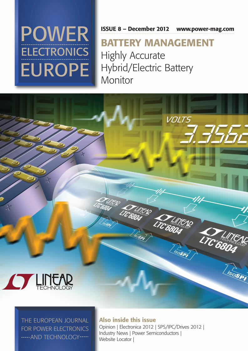
BATTERY MANAGEMENTHighly Accurate Hybrid/Electric Battery Monitor
ISSUE 8 – December 2012 www.power-mag.com
Also inside this issueOpinion | Electronica 2012 | SPS/IPC/Drives 2012 | Industry News | Power Semiconductors | Website Locator |
01_PEE_0812_p01 Cover 29/11/2012 15:11 Page 1

oigne ohh ttiW
itisner dewof pe osaecrng in
e ths tcinortcelr eewon ps ie
e cafretnl iamrehe t
serutaeFin aM
libiale rmtesysradnaty stilauq
t oos neoM dIT
u plarnee ghetcieps, elairetam
ewon peewtebg
.ytis teludor mewor pon fevis gdrmreht tsewoe lhe tdivory pln
.lebaliav aslaireta meospr-erd pnr aod fepolevey dllacimeocek bnistaed hne aludor m
f pg i
me aitefit lsegnoe lhe tveicho as ts tllifluo fslt a, iecnatsisel ram
eludos m’noenifno Id teilppaeh. A tegnellar chegras a lme
n p
t sehgid hnme at sehgie hhs t
s mrofreptus oee cafretnl iamre
d sImdiefilpimSor pdecudRe
stifeBen
o fdezimitpOoe tho ty trD
deilpap-erPs tsaln ct iseB
serutaeFin aM
tilibiltgintnuom
ngirutcafu mann iemi tsseco
elduo Mnoeinfn Idetadice drr dochuo
seludo Mnoeninf Io tecnatsisel ramrehs t
se
50
60
70
80
90
010
011
][K
b ma
–T jT
hadevorpmIh tdezimitpOyd sesaecrnIyd sesaecrnI
.noeinfin.www
cnanetina mff m oesa c ingg inindlntnemegana malmreh
meitefim letsyytilibailem retsy
imt/moc
e
C°521, h0001t setssertSgnirote Srutarepmeh Tgi: HSTH*
]skeeW* [STn He imiT
, g
-3DO M-2DO M-1DOM
54
noitulo-SXFI
02_PEE_0812_Layout 29/11/2012 13:00 Page 1

CONTENTS
www.power-mag.com Issue 8 2012 Power Electronics Europe
3
Editor Achim ScharfTel: +49 (0)892865 9794Fax: +49 (0)892800 132Email: [email protected]
Production Editor Chris DavisTel: +44 (0)1732 370340
Financial Clare JacksonTel: +44 (0)1732 370340Fax: +44 (0)1732 360034
Circulation Manager Anne BackersTel: +44 (0)208 647 3133Fax: +44 (0)208 669 8013Email: [email protected]
INTERNATIONAL SALES OFFICESMainland Europe: Victoria Hufmann, Norbert HufmannTel: +49 911 9397 643 Fax: +49 911 9397 6459Email: [email protected]
Armin Wezelphone: +49 (0)30 52689192mobile: +49 (0)172 767 8499Email: [email protected]
Eastern US Karen C Smith-Kerncemail: [email protected] US and CanadaAlan A KerncTel: +1 717 397 7100Fax: +1 717 397 7800email: [email protected]
Italy Ferruccio SilveraTel: +39 022 846 716 Email: [email protected]
Japan:Yoshinori Ikeda, Pacific Business IncTel: 81-(0)3-3661-6138Fax: 81-(0)3-3661-6139Email: [email protected]
TaiwanPrisco Ind. Service Corp.Tel: 886 2 2322 5266 Fax: 886 2 2322 2205
Publisher & UK Sales Ian AtkinsonTel: +44 (0)1732 370340Fax: +44 (0)1732 360034Email: [email protected]
Circulation and subscription: Power ElectronicsEurope is available for the following subscriptioncharges. Power Electronics Europe: annual chargeUK/NI £60, overseas $130, EUR 120; single copiesUK/NI £10, overseas US$32, EUR 25. Contact: DFA Media, Cape House, 60a Priory Road, Tonbridge,Kent TN9 2BL Great Britain. Tel: +44 (0)1732 370340. Fax: +44 (0)1732360034. Refunds on cancelled subscriptions willonly be provided at the Publisher’s discretion, unlessspecifically guaranteed within the terms ofsubscription offer. Editorial information should be sent to The Editor,Power Electronics Europe, PO Box 340131, 80098Munich, Germany. The contents of Power Electronics Europe aresubject to reproduction in information storage andretrieval systems. All rights reserved. No part of thispublication may be reproduced in any form or by anymeans, electronic or mechanical includingphotocopying, recording or any information storageor retrieval system without the express prior writtenconsent of the publisher.Printed by: Garnett Dickinson.ISSN 1748-3530
PAGE 6
Electronica 2012
PAGE 12
SPS/IPC/Drives 2012
PAGE 15
Industy NewsDimmable driver for High-Power LEDs
LED Driver with FrequencySynchronization and PWM Dimming
PAGE 30
High-Speed TRENCHSTOP 5 IGBTIGBTs are historically known for having long tail
currents with focus on drive applications and
anything switching up to 30 kHz was known as
“High Speed”, where conduction losses were
penalized to get switching losses down. In
2008, Infineon launched a ground breaking
technology called the HighSpeed3, which is the
highest efficiency IGBT capable of switching up
to 100 kHz with a MOSFET-like turn-off
switching behavior. Now Infineon’s
TRENCHSTOP™ 5 technology is capable of
switching well beyond 100 kHz. Mark Thomas,
Discrete IGBT Product Marketing, Infineon
Technologies AG, Villach, Austria
PAGE 33
Website Product Locator
Highly AccurateHybrid/ElectricBattery MonitorLithium-Ion batteries require considerable care if theyare expected to operate reliably over a long period.They cannot be operated to the extreme end of theirstate-of-charge (SOC). The capacity of Lithium-Ioncells diminish and diverge over time and usage, soevery cell in a system must be managed to keep itwithin a constrained SOC. To provide sufficient powerfor a vehicle, tens or hundreds of battery cells arerequired. These cells must be configured in a longseries; as much as 1000 V and higher. The batteryelectronics must operate in this very high voltageenvironment and reject common mode voltage effects,while differentially measuring and controlling each cellin these strings. The electronics must be able totranslate information from the battery stack to a centralpoint for processing. On top of these requirements,operating a high-voltage battery stack in a vehicle orother high-power applications imposes toughconditions, such as operation with significant electricalnoise and wide operating temperatures. The batterymanagement electronics are expected to maximizeoperating range, lifetime, safety and reliability, whileminimizing cost, size and weight. Linear Technology’s3rd generation Battery Management System providesmany desirable features for monitoring large anddistributed battery packs in vehicle and industrialapplications. Full article on page 25.
Cover supplied by Linear Technology Corporation
COVER STORY
PAGE 5
Opinion
p03 Contents_p03 Contents 30/11/2012 08:56 Page 3

MOTOR CONTROL
...for highest reliability applications
OR CONTROLMOT
OR CONTROL
available with extended voltage ratings.and (IPM) Modules . Besides IGBTto several 100kW
a wide range of Industrial Motor Control applications from 0.4kWofElectric Mitsubishi
available with extended voltage ratings.(DIPIPMIPM Package Inline Dual and
Modules also Intelligent Power. Besides IGBTa wide range of Industrial Motor Control applications from 0.4kW
Semiconductors Power of variety big a fers of
design as well as a high power cycling capability to ensure highest
The power modules feature state of the art CSTBT
are)TM(DIPIPM Modules also Intelligent Power
a wide range of Industrial Motor Control applications from 0.4kWforSemiconductors
design as well as a high power cycling capability to ensure highest
The power modules feature state of the art CSTBT
design as well as a high power cycling capability to ensure highest
chip tech-TMThe power modules feature state of the art CSTBT
[email protected] · www
[email protected] · www
.mitsubishichips.eu
04_PEE_0812_Layout 29/11/2012 14:02 Page 1

OPINION 5
www.power-mag.com Issue 8 2012 Power Electronics Europe
Recent shows have underlined the potentials ofenergy saving through latest achievements inpower electronics. Cree entered at Electronica the Power Module
market with a self-designed 1200 V / 100 A half-bridge at Electronica. Regarding switchingfrequency the power module’s low-inductionconstruction allows for 100 kHz maximum.According to Cree for inverter applications thesweet spot is around 50 kHz. Also ROHM’s fullSiC power module – integrating SiC MOSFETs andSBDs enables high frequency operation above100 kHz and can reduce losses by 85%compared with conventional Si IGBT modules.Additionally Semikron announced at SPS/Drivesits activities in Silicon Carbide Power Modules.First poducts shown were a SiC hybrid modulefeaturing a SiC free-wheeling diode and a Si IGBTswitch. Efficiency is 97 % at 30 kHz switchingfrequency compared to 94.5 % with a Si diode.Second product is a 20 A MiniSKiiP incorporatinga SiC MOSFET and a SiC diode allowing for anincrease of 150 % (7 kW to 3 kW) in outputpower at 30 kHz switching frequency comparedto a Si IGBT module. Finally 10 kW SiC SEMITOPand 300 kW SKiM modules with sinteredinterconnects and customer-specificconfigurations will be available on request.Compared with conventional Silicon-based
power devices, GaN-based power devices arerated up to 600 V and feature also lower on-resistance and the ability to perform high-frequency operations. Since these characteristicsimprove the conversion efficiency of powersupply units and make them more compact, thistechnology is ideal not just for servers but for abroad range of applications including solar anddrive inverters, battery chargers or electricvehicles. A 400 W appliance inverter prototype has been
demonstrated by International Rectifier using 600V GaN switches a for driving the motors. TheGaN-on-Silicon devices replacing IRAM IGBTsexhibit six times lower conduction and two timeslower switching losses at an output power of 415W in only 10 percent of the package size for thepower stage. And considering that the GaNswitches can operate without the need for aheatsink a reduction of a factor 100 for the power
stage volume compared to the existing IGBTsolution can be realized. The company’s ultimategoal is to integrate a GaN Power System on achip. Fujitsu Semiconductor plans to commercialise
GaN power devices on a Silicon substrate,increasing the diameters of the silicon wafers andenabling low-cost production. The companybegan work on GaN technology in 2009 andbegan providing specific power-supply-relatedpartners with sample GaN power devices in 2011.Since then, Fujitsu has worked on optimizing thedevices for use in power supply units. A mass-production line for 6-inch wafers has beenestablished at Aizu-Wakamatsu plant, full-scaleproduction of GaN power devices will begin in thesecond half of 2013. A prototype server power-supply unit incorporating a GaN PFC achievedoutput power of 2.5kW. This impressiveperformance makes GaN power devices suitablefor use in high-voltage, large-current applications. Also so-called wafer level magnetics (WLM)
developed by Enpirion present a leap intraditional technology, which will take magneticcomponents from their 3-dimensional discreteshape to a planar 2-dimensional thin-film formthat can be deposited with standard waferprocesses on top of CMOS wafers. WLM is fullyqualified for full-scale mass production in a highvolume foundry and enables Power System-on-Chips based on electroplated wafer levelmagnetics. Developed with a view to achievingmonolithic Power System-on-Chips, the WLMtechnology can be easily transferred to othermicro-magnetic applications. Increased switchingfrequency allows the use of smaller inductorsutilizing electroplated WLM materials that can bepost-CMOS processed. The Fe-Co based alloy(FCA) has high resistivity, low coercivity andmaintains high effective permeability atfrequencies higher than 20MHz. FCA’s highmagnetic saturation makes it suitable for use assingle or multiple layers in power circuits, where itis compatible with flip-chip, wire-bonding andsolder re-flow packaging methods. Enpiriondeveloped a turnkey process module, whichfeatures low cost of ownership plating equipmentto deposit FCA on 6 inch or 8 inch wafers. Thistechnology already achieves Power System-on-Chips with rated currents up to 1.5 A.Thus innvation never stops and will lead to new
devices and applications in 2013. We wish ourreaders a good jump into the (happy) new year.
Achim ScharfPEE Editor
InnvationNever Stops NEW
GENERATION OF LIQUID
COLD PLATES
Superior thermal
performance
Various standard types
Solutions for any
application
- AUSTRIA DAU GmbH & Co KG
Tel +43 (0) 31 43 / 23 51 - 0 [email protected]
superior low temperature difference over complete module cooling areaavailable as single or multiple cooling unit (up to 7 modules)
also for new PRIME PACK™ MODULE 2 and 3extreme low thermal resistance
- USA DAU Thermal Solutions
North AmericaPhone: 585-678-9025
A MIBA GROUP COMPANYwww.dau-at.com
TESCOLD PLAOF LIQUID
TION GENERANEW
.dau-at.comwwwANYA GROUP COMPA MIB
TES
TION
ANY
TESCOLD PLA
arious standard typ
V
TES
pes
performSup rior thermal perior th
rformance
t l thermal resistanceextreme low therm MODULE 2 and 3
ACK™ PRIME P
l al
d l ling area
multiple cooling unit available as single or module cooling areaover complete
differen temperature
multiple cooling unit available as single or
a
nce
applic
1 523 / 43 1 3(0) el +43 TDAU GmbH & Co KG - AUSTRIA
Solutions for any utions
pplication
(up to 7 modules)multiple cooling unit
0 -
- AUSTRIA
multiple cooling unit
om.casuuad.wwwom.casuuad@selas
5209-867-585:ehonPaciremh AtroN
ns oituoll SamrehU TADA S- U
5
ns
05_PEE_0812_NEW_p05 Opinion 29/11/2012 15:55 Page 5

6 ELECTRONICA 2012 www.electronica.de
Issue 8 2012 Power Electronics Europe www.power-mag.com
Center of the World for ElectronicsThe 25th electronica, the International Trade Fair for Electronic Components, Systems and Applications,closed on November 16 in Munich with more than 72,000 visitors. A total of 2,669 exhibitors from 49countries presented the future of electronics and showcased application-oriented solutions during the four-day fair, which revolved around intelligent and energy-efficient solutions in the sectors for energy storage,LEDs and smart grids. The next electronica takes place in Munich from November 11 – 14, 2014.
Norbert Bargmann, Deputy CEO of Messe München, was more than satisfiedwith the fair’s results: “This year’s fair confirm the electronics industry’ssignificance as the most important branch of industry in the world. The marketis constantly confronted with new requirements that manufacturers meet withintelligent solutions. This year’s hot topics included energy-efficienttechnologies and the latest developments in medical electronics. Automotiveelectronics, which account for an ever-increasing share of modern motorvehicles, was central theme in all exhibition categories: from control elementsfor energy harvesting and battery management to new charging techniques forelectric automobiles.”
Besides Germany, the countries with the largest contingents of visitors wereItaly, Austria, Great Britain and Northern Ireland, Switzerland, France, theRussian Federation and the USA, in that order. The number of visitors fromCanada, the Russian Federation, Turkey, the USA, the Czech Republic, Austriaand Asia saw a significance increase. Nicole Schmitt, Exhibition Group Directorfor electronica: “The large percentage of international guests proves once againthat electronica is the world’s leading trade fair for the electronics industry.”
Besides Germany, the countries with the largest numbers of exhibitors wereChina, Taiwan, the USA, Great Britain, Italy, Hong Kong, France, Switzerland andJapan. In total 2,669 exhibitors from 49 countries were on stage.
The industry is looking forward to the year 2013 with cautious optimism.That was also confirmed by Kurt Siever, Head of the Electronic Componentsand Systems Association and the PCB and Electronic Systems Association inthe ZVEI (German Electrical and Electronic Manufacturers’ Association). “After aminor slump of two percent in 2012 down to $ 460 billion, we expect theworld market for electronic components to grow by some four percent in2013. Forecasts also call for an increase in sales in the global semiconductorindustry in 2013. The European market for electronic components of € 46billion in 2012 is forecasted to grow slightly by one percent.”
Market opportunities for the futureThe speakers at this year’s CEO Round Table all agreed on one thing: “Smartgrid” will be one of the electronics industry’s key topics in the future. The fourCEOs from Freescale Semiconductor (Greg A. Lowe), STMicroelectronics(Carlo Bozotti), NXP Semiconductors (Rick Clemmer), and InfineonTechnologies (Reinhard Ploss) saw that as a great opportunity for thesemiconductor industry. After all, without smart meters and smart lightingsolutions, it will not be possible to ensure the energy-efficient supply ofelectricity in the future. The industry still faces a few challenges. Electricity mustbe fed, transported and controlled, and several components are needed to doso. The interaction and reliability of these components are essential to avoidultimately ending up in the dark.
NXP’s Clemmer expects an annual growth of 20 % for smart meters –providing a great opportunity for (power) semiconductors. According to ST’sBozotti roughly 20 % of the capacity in the traditional grid is used to managethe power peaks, which is highly inefficient. Smart meters can improve thissituation significantly. In Italy already 33 million smart meters are installed.Freescale’s Lowe added, that China will install 300 million smart meters by theyear 2016. And Infineon’s Ploss views the smart grid as the Internet of power.
But getting out the reactive power out of the grid one have to move to high-voltage DC transmission which also can improve electrical power distributionefficiency by a factor of 2.
Infineon also announced FY 2012 results ended September. The worldwideeconomic slowdown had the greatest effect on demand for powersemiconductors for use in industrial, computing and consumer applications,and this is the case not only with Infineon.
Revenue in the Power Management & Multimarket segment fell by sevenpercent and that of the Industrial Power Control segment by nine percentcompared to fiscal year 2011. By contrast, the Automotive and Chip Card &Security segments both achieved revenue growth of seven percent. Overall,revenue from these four core segments, at €3.774 billion, almost reached lastfiscal year’s level. “Our strongest pillar remains Automotive, here we profitedfrom the successes of premium manufacturers and from growth in Asia. In thefourth quarter of fiscal year 2012, our Automotive revenues dropped slightly to416 million euros. After record quarters, this is the result of seasonaldevelopments”, CEO Reinhard Ploss explained. “What do we expect in thecurrent fiscal year? The market research company IHS is forecasting a rise inworldwide automobile production of only 1.9 percent in calendar year 2013.We are not immune to the structural weaknesses in the European automobilemarket and slower growth in North America, India and China. For the runningquarter we expect a slight decline in revenues. In the Industrial Power Controlsegment we are feeling the effects of investment slowdowns by our industrialcustomers, thus revenues dropped by nine percent during fiscal year 2012”.
“Macroeconomic headwinds are getting stronger and we do not see thischanging in the near term. We are therefore forecasting a drop in revenue for
The CEO Round Table focused on the impact of the Smart Grid for (power)semiconductors
Electronica_Layout 1 29/11/2012 14:23 Page 6

www.electronica.de
www.power-mag.com
The Perfect Fit
the 2013 fiscal year. Nonetheless, Infineon continues to focus on energyefficiency, mobility and security”, Ploss stated.
International Rectifier is also cautious about the running fiscal year. “Thoughthe last quarter came in better than our guidance, industry conditions remainchallenging,” stated CEO Oleg Khaykin. “While the high performancecomputing and server end markets were strong, the increase was offset bylower demand in our other major end markets, particularly appliances andindustrial goods.” For the running quarter customer inventory levels appear tobe at relatively reasonable levels, demand continues to remain weak andorders have not shown signs of improvement through the first part of thequarter. “As such, we currently expect December quarter revenue to rangebetween $215 and $230 million. We remain optimistic about our medium-term growth prospects and expect that our operational restructuring activitieswill help to return to profitability,” Khaykin said at Electronica. Overall heexpects revenues around $1 billion for the full FY 2013.
And Power Module manufacturer Vicor (www.vicorpower.com) faceseight consecutive quarters of declining earnings and is in a phase oftransistion. “Among our traditional market segments, the defense electronicshas experienced a sustained decline in revenue due to federal budgetconstraints. Similarly, our revenues from supercomputing platforms aresubstantially reduced because of slowing demand and low cost competition.Demand in our commercial market segments, notably industrial equipmentand transportation, has been characterized recently by greater uncertainty, asbusinesses, with limited visibility into their own prospects, reduce theirspending and investment. This has been experienced across our Europeancustomer base, given that region’s decline into recession, and increasinglyacross our North American customer base, as customers defer businessdecisions until the political stalemate associated with the pending federalbudget ‘sequestration’ is addressed”, said CEO Dr. Patrizio Vinciarelli.
GaN at workIR took the opportunity to demonstrate 600 V GaN switches in a 400 Wappliance inverter prototype for driving the motors. “The GaN devices replacing
“The smart grid is theInternet of power. High-voltage DC transmissioncan improve electricalpower distributionefficiency by a factor of2”, stated Infineon’s CEOReinhard Ploss
“While GaN is expectedto cannibalize some ofour existing business weexpect to increase ouroverall market share”,said IR’s CEO OlegKhaykin.
Electronica_Layout 1 29/11/2012 14:23 Page 7

8 ELECTRONICA 2012 www.electronica.de
Issue 8 2012 Power Electronics Europe www.power-mag.com
IRAM IGBTs exhibit six times lower conduction and two times lower switchinglosses at an output power of 415 W in only 10 percent of the package size forthe power stage. And considering that the GaN switches can operate withoutthe need for a heatsink a reduction of a factor 100 for power stage volumecompared to the existing IGBT solution can be realized”, said Tim McDonald,IR's Vice President of Emerging Technologies. “We plan to release acorresponding product by end of calendar year 2013, a family of discretecascoded 600 V GaN switches with 50 to 200 milliohm on-resistance. In2014 we plan to release a series of 600 V-modules including µIPMs andmoving forward our roadmap includes GaN Power ICs integrating powertransistors and drivers. The ultimate goal is to integrate a GaN Power Systemon a chip, perhaps by the year 2018!”“And by the way, the IGBT Power Module packaging used in today's inverter
is very expensive”, added IR's CEO Oleg Khaykin at the live demo. “It has alarge DBC substrate, requires an expensive over-molding process and needsa large heatsink.”
More power with SiCCree (www.cree.com), so far supplier of Silicon Carbide (SiC) wafers fordevice manufacturers and SiC devices such as Schottky Barrier Diodes (SBD)and MOSFETs up to 1700 V breakdown voltage, now enters the PowerModule market with the self-designed 1200 V / 100 A half-bridgeCAS100H12AM1.This subcontractor-made power module, measuring 87.5 mm x 50 mm,
contains five Cree 20 A / 1200 V MOSFETs featuring zero turn-off tail currentand five 10 A / 1200 V Schottky Diodes featuring zero reverse recoverycurrent per high- and low-side legs – in total ten SiC MOSFETs and ten SiCdiodes. The switches are rated for 150°C junction temperature, the diodes for175°C. These devices are not taking advantage of the inherent highertemperature capabilities of SiC well beyond 200°C. The module itself is ratedat 125°C case temperature and is available with AlSiC or Si3N4 DBCbaseplate. The initial product offering still uses aluminum bond wires due tothe subcontractor’s production capabilities, but advanced interconnectiontechnologies are investigated for future products. Regarding switching frequency the power module’s low-induction
construction allows for 100 kHz maximum. According to Cree for inverterapplications the sweet spot is around 50 kHz. The new All-SiC Power Moduleis targeted as building block for system designs in Solar, UPS and motor driveinverters up to 100 kW; light wind and traction inverter applications as well ashigh-power auxiliary converters.The Cree SiC power module is available through distributors DigiKey
(www.digikey.com) and Mouser (www.mouser.com). Japanese ROHM (www.rohm.com/eu) has advanced the development of
next-generation SiC Schottky Barrier Diodes and MOSFETs backed by themanufacturing capability of SiCrystal (Erlangen/Germany) as part of the
“Our new full-SiC 1200V/100 A power modulesare very competitivelypriced”, stated Cree’sMarketing Manager PaulKierstedt
http://siliconpower.danfoss.com
Drive happy while staying cool Reliable power density for tomorrow’s vehiclesIt cannot be stressed enough: e cient cooling is the most important feature in power modules. Danfoss Silicon Power’s cutting-edge ShowerPower® solution is designed to secure an even cooling across base plates. In addition, our modules can be customized to meet your automation requirements in detail, o ering low weight, compact design, extended life and very low lifecycle costs. In short, when you choose Danfoss Silicon Power as your supplier you choose a thoroughly tested solution with unsurpassed power density.
Please go to http://siliconpower.danfoss.com for more information.
MAKING MODERN LIVING POSSIBLE
Electronica_Layout 1 29/11/2012 14:23 Page 8

www.electronica.de ELECTRONICA 2012 9
www.power-mag.com Issue 8 2012 Power Electronics Europe
company. The combination of low loss and high voltage capability as well asfast recovery time makes these devices suited for many applications, includingPFC (power factor correction) circuits, converters and inverters as used in
EV/HEV and industrial units. ROHM’s new high-voltage isolated SiC gatedrivers facilitate low-power consumption and small designs. Together with SiCdevices the new series guarantees a stable, high speed operation even in highpower regions. In addition, ROHM’s full SiC power module – integrating SiCMOSFETs and SBDs enables high frequency operation above 100 kHz.The new modules featuring aluminum bond wiring integrate a dual-element
SiC SBD/ SiC MOSFET pair that reduces loss during power conversion by 85%compared with conventional Si IGBT modules. In addition, high-frequencyoperation of at least 100kHz is possible. And although the modules are ratedat 100A, their high-speed switching capability, reduced loss, and improvedheat dissipation characteristics make them replacements for 200-400 A Si-IGBT modules. “Replacing a conventional 400 A-class IGBT can cut volume by50 %, and the lower heat generated requires less cooling countermeasures,contributing significantly to end-product miniaturization”, said EuropeanProduct Marketing Manager Marc Frochte. First SiC power modules targetedfor automotive applications (Honda) have been shown already at Electronica2010.Also new IGBTs have been introduced by Infineon and International
Rectifier, advanced LED drivers by Power Integrations (www.powerint.com)and AC/DC power modules by Vicor (www.vicorpower.com).
“Our new generation of1200 V/100 A SiC powermodules can cut volumeby 50 percent compared toconventional Si modules”,said ROHM’s Marc Frochte
“The electrification of the powertrain in the automobile and replacement ofhydraulic controls is today’s major trend, and last but not least multi-stageboard-nets”, pointed out Vishay’s (www.vishay.com) SVP Business Dev.Norbert Pieper. Fuel savings and efficiency improvements are the steps to betaken. SMPS instead of linear regulators could improve efficiency up to 5 %,incorporation of start-stop ISG up to 10 %, BLDC motors for cooling andheating also up to 10 %, electronic power steering (EPS) also up to 10 %,double-clutch transmission with BLDC motors up to 15 % and finally the 48 Vboard-net for driving fully electric applications more powerful also up to 15 %.“Savings on what you have is better than looking for alternatives”, Pieperstated. The trend towards more BLDC motors is supported by Vishay throughnew power semiconductor packages which can be directly integrated into themotor casing.
Power electronics improve fuel efficiencySome 300 participants from 19 countries attended the electronica automotive conference anddiscussed on the topics infotainment, safety and last but not least fuel efficiency and CO2reduction by using (power) electronics.
Infineon’s (www.infineon.com) System Architect Body Electronics Dr. AlfonsGraf focused on energy efficiency improvements through optimization of thevarious subsystems in the vehicle. According to his assumptions efficiency orelectrical power and weight have a significant impact on the fuel consumptionand therefore CO2 emissions. In example 100 W extra electricity consumptionfor air conditioning or other consumers will add to an extra 0.1 l of fuelconsumption per 100 km, also the addition of 50 kg of weight. Additional fuelconsumption of 1 l / 100 km will increase CO2 emission by roughly 25 g / km.In other words, 1 g CO2 / km less equates to 40 W or 20 kg less addingadditional cost of 5 – 95 Euro to manufacture the car. On the other hand –savings of 1 W will cost the car manufacturer in average between 0.25 and 0.55Euro, 1 A less amounts to 3 – 7 Euro, and 1 kg less weight costs 3 – 5 Euro. According to Graf, for fuel savings it is mandantory to reduce the weight and
power consumption of the car significantly. But the costs to improve energyefficiency will increase with the increasing complexity of the envisionedsolutions. Today Start-Stop systems or some electric accessories for power-on-demand such as electric water pump, variable-speed air compressor, andelectric power steering are more or less common. These items will add some25 Euro in order to save 1 g CO2 emission per km. Next step to be taken inthe time frame 2013 – 2016 will cover the implementation of advanced Start-Stop systems with recuperation of energy, perhaps a 48 V board net, LiIonbattery, and downsizing of the combustion engine via high-pressure directinjection and variable turbo charging by electric motor control. To install suchsystems the cost will definitely go up around 35 Euro. For the years to comebeyond 2016 Graf would expect a further downsizing hand in hand withadvanced hybridization or range extenders and perhaps more e-vehicles onthe road. But to achieve such a scenario one has to spend some more moneyin the range of 50 Euro to save 1 g CO2 per km. In order to realize thisfunctionality the semiconductor content will increase up to 15 Euro for eachsaved gram of CO2. And, by the way, the EU CO2 target is 95 g / km.There are many possibilities for reducing electrical power through more
efficient solutions already available such as replacing incandescent bulbs byEfficiency improvements by implementing more electric/electronic functions in the car
Source: Vishay
Electronica_Layout 1 29/11/2012 14:23 Page 9

10 ELECTRONICA 2012 www.electronica.de
Issue 8 2012 Power Electronics Europe www.power-mag.com
LEDs (headlamps, rear lights, ambient lighting) saving a total of 50 W; PWMregulated fuel pump (saving ~ 80 W), electric power steering (savings ~ 250W or 6 g CO2), or substitution of relays by power semiconductors. Themajority of vehicles contain 7 – 15 relays in the power distribution center, byusing new technologies size and weight can be greatly improved, but also theprice point by 18 Euro. “To improve fuel efficiency and overall efficiency of acar we have to go many small steps and all of these steps are supported bysemiconductors”, Alfons Graf concluded.
regulations particularly in Europe there are constrains on the input of thevehicle (fuel) and on the output (emissions), in order to deal with thatefficiency has to be improved. “And this is the whole motivation for designinghybrid electrical vehicles. The main inverter in EVs has to be highly reliablesince it replaces the internal combustion engine. And it is subjected to highertemperatures. Thus we have developed a new packaging and interconnectionconcept called “Solderable Front Metal” allowing for double-sided cooling aswell as eliminating the bond wires”.Brand name of this technology is CoolIR? aimed for applications above 50
kW incorporating MOSFETs/IGBTs/Diodes (up to 1200 V) with die sizes up to
International Rectifier’s (www.irf.com) Senior Manager Automotive PowerBenjamin Jackson outlined the transition from traditional cars towards electricalvehicles (EVs). The ongoing rise of fuel prices and the CO2 emission
By using (power) semiconductors size and weight of a power distribution center can begreatly improved Source: Infineon Technologies
Bondless die assembly and manufacturability of CoolIR?Die Source:IR
225 mm?. The thin chips (70 µm) are mounted onto a DBC substrate for CTEmatching with the module substrate, for topside electrical isolation and for thepossibility to mount the IGBT collector up or down. Thus no handling of thethin bare dies is required, wire bonding is eliminated and pick & placemanufacturing for mounting on module substrate can be used. By having flipped dies the collector and emitter pads the power IGBTs in a
half-bridge can be placed in an adjacent manner to each other – simplifyingsignificantly the routing and reduces stray inductance. And by eliminating thewire bonds not only inductance and on-resistance can be reduced, but alsoreliability can be drastically improved. “Early prototypes have demonstratedmore than 810,000 power cycles at 85°C junction temperature, whereastraditional wire bonded modules see lifetimes of around 100,000 cycles atthis temperature”, Franklin concluded. AS
Layout of a compact half-bridge using CoolIR?Die Source:IR
To receive your own copy of
POWER ELECTRONICS EUROPE
subscribe today at:
www.power-mag.com
Electronica_Layout 1 29/11/2012 14:23 Page 10

Power and productivityfor a better world™
1600000 Volt. Thyristor converters deliver energyto megacities via one single transmission line.
ABB Switzerland Ltd / ABB s.r.o.www.abb.com/[email protected]
ABB Semiconductors’ Phase Control Thyristor has been the backbone of the highpower electronics industry since its introduction almost 50 years ago. Its field ofapplication ranges from kW DC-drives and MW rated load commutated frequencyconverters to GW converters for HVDC transmission.ABB’s thyristor portfolio includes both PCT and Bi-directionally Controlled Thyristor(BCT) press-pack devices with ratings of 1600 V – 8500 V and 350 A – 6100 A.For more information please visit our website: www.abb.com/semiconductors
11_PEE_0812_Layout 29/11/2012 14:04 Page 1

12 SPS/IPC/DRIVES 2012 www.mesago.com/sps
Issue 8 2012 Power Electronics Europe www.power-mag.com
“Our exhibitors are happy”, said Mesago’s Head Johann Thoma. “We havemore exhibitors from China, Russia and the USA certainly looking forbroadening their customer base in Germany and Europe. The Euro discussionis more a psychodelic one since investments in dives and automation aremore or less independent from this mood”.A detailled overview on the current market situation has been given by the
ZVEI, the German Central Assoziation for the Electrical/Electronics Industry.“The electrical drive industry in Germany can look back for 17 and 20 percentgrowth in the years 2010 and 2011 respectively. In 2011 the market rose upto Euro 10.7 billion and exceeded the result of 2008. The market for motorsincreased by 17 percent in 2011, the market for inverters by 24 percent andthus crossed for the first time the Euro 3 billion barrier. For the running yearwe expect a slight growth up to Euro 10.8 billion, driven mainly by the driveelectronics growing by some 2.2 percent. For 2013 we expect a stabilization,in other words a stagnation at high level”, expressed Günther Baumüller,member of the ZVEI board automation. “The finacial markets and politicaldecisions have a huge impact on the real economy what is making predictionsnot easier. In this context it is interesting to see how the regional markets willdevelop. In the Americas and in Asia the drive business runs much better thanin Europe, particularly in Southern Europe”.The EU Directive M640/2009 will make electrical drives more efficient,
which means that by the year 2015 drives with an output power above 7.5 kWsolely confirming to energy efficiency class IE3 can be sold across the EU,alternatively IE2 motors with an additional variable speed controller. From theyear 2017 IE3 motors have to be equipped with frequency inverters. “And thatis just the beginning. Since March 2012 the European Commission hasinitiated four studies named lots 28 to 31 evaluating the energy savingpotentials in drives, pumps and compressors. These new ideas will change theworld of drives and machines drastically, since alls relevant components andeven the designed systems will in the future evaluated according to efficiencyclasses”, Baumüller concluded.
Power electronics for invertersWhat can be achieved with modern power electronics has been shown byMitsubishi Electric with the MiEV showing the various subsystems such as
frequency inverter and battery monitor, one of the eyecatchers at thefairgrounds. Infineon (www.infineon.com/tim) demonstrated for the first time for the
public its activities in Thermal Interface Materials for Power Modules.
Stagnation at High LevelWith a record number of 1,461 exhibitors this year’s SPS IPC Drives has been held on NurembergsFairgrounds, a slight increase compared to the 1,429 exhibitors in 2011. The result of this event arealso of interest for the power electronics industry, because it is an indicator of what happens intheir important customer base.
ABOVE: Electrical cars consume a heavyamount of power electronics as shown byMitsubishi
LEFT: German market development forelectrical drives (in € billion)
Source: ZVEI
SPS_Layout 1 29/11/2012 14:29 Page 12

Solid State Alternatives To TWT Amplifiers
Copyright © 2012 AR. The orange stripe on AR products is Reg. U.S. Pat. & TM. Off.
ISO 9001:2008Certified
ar europeNational Technology Park, Ashling Building, Limerick, Ireland 353-61-504300 www.ar-europe.ie
www.ar-europe.ie/contact.php
The New 1 – 2.5 GHz “S” Series Solid State Power Amplifiers There are several important things to consider when choosing a test amplifier. Things like harmonics, linearity, durability, power, reliability, and of course life cycle cost. Too often, you have to settle for an old TWTA design approach to achieve this power in such a small footprint, but now you can have it all in a state-of the-art affordable instrument to meet your demanding requirements. With AR’s new 100, 250 and 500-Watt 1-2.5 GHz “S” Series amplifiers you can have the reliability and performance advantages of solid state without the hassles that the old TWTA designs have. And if 500 watts wasn’t enough, we will soon be coming out with even higher power. And because it’s made by AR, it’s backed by a worldwide service and support network that’s second to none. So why settle for just any amplifier when you can get one with all the features you’ve been wishing for?
13_PEE_0812_Layout 29/11/2012 14:07 Page 1

14 SPS/IPC/DRIVES 2012 www.mesago.com/sps
Issue 8 2012 Power Electronics Europe www.power-mag.com
Convertional thermal pastes and other materials are designed for lowertemperatures and packages and not for the large area of power modulebaseplates or DBCs. Nevertheless, though power modules are sold in relativelylow volumes the area to be deposited by thermal interface materials isrelatively big compared to chips in computing applications, “Henkel/Loctiteviews this segment as a market opportunity and works with Infineon on anappropriate solution in a 7-year project covering hundred man-years”, saidInfineon’s Application Engineer Martin Schulz. Thixotrophy is the academic term for the properties of this joint efforts.
Certain gels that are thick under normal conditions become thin or flow whenstressed. “In our case the thermal interface pre-applied in small circles overthe baseplate becomes less viscous above 45°C and forms a thin layerfeaturing less thermal resistivity than the standard module. Power cycling tests
on a 2 MW inverter confirm that reliability can be increased by a factor 4. Itdoes not degrade and keeps its thermal conductivity across the completebaseplate. Additonal measures ensure that the hot spots below the heat-generating semiconductors have high thermal conductivity”, Schulz stated. Thetechnology is suitable for power modules equipped with powersemiconductors in the 150°C class.LEM (www.lem.com) introduced its new HLSR series of current
transducers, that provide a cost-effective alternative to resistiveshunt/optocoupler configurations for insulated current measurements up to50 A. The five new HLSR transducers will satisfy application requirements in,for example, industrial inverters and motor drives; switch-mode anduninterruptible power supplies; specialist power supplies such as weldingunits; air conditioning; home appliances; but also in renewable-energysystems, for example, in solar combiner boxes and in solar inverters to trackthe maximum-power-point (MPPT). LEM’s HLSR series uses open-loop Hall-effect current sensing technology, to measure AC, DC or pulsed currents withnominal values of 10, 20, 32, 40 or 50 A RMS. LEM’s proven expertise inopen-loop Hall-effect technology allows these new devices to achieve aresponse time of 2.5 µs, with very low gain and offset drift over theiroperating temperature range of -40 to +105 °C.Semikron (www.semikron.com) announced on the booth its activities in
Silicon Carbide Power Modules. First poducts shown were a SiC hybrid module
Infineon’s Martin Schulz demonstrated power modules with pre-applied thermalinterface material
LEM announced new current transducers in the 50 A range
featuring a SiC free-wheeling diode and a Si IGBT switch. Efficiency is 97 % at30 kHz switching frequency compared to 94.5 % with a Si diode. Secondproduct is a 20 A MiniSKiiP incorporating a SiC MOSFET and a SiC diodeallowing for an increase of 150 % (7 kW to 3 kW) in output power at 30 kHzswitching frequency compared to a Si IGBT module. Finally 10 kW SiCSEMITOP and 300 kW SKiM modules with sintered interconnects andcustomer-specific configurations will be available on request. AS
Semikron entered the SiC Power Module market at SPS/IPC/Drives
SPS_Layout 1 29/11/2012 14:29 Page 14

INDUSTRY NEWS 15
www.power-mag.com Issue 8 2012 Power Electronics Europe
Innovation by Tradition
E FOR TRANTITUTSSUB
FORMERSE FOR TRAN
S – 5 LETTERSFORMER
LOW OHMIC PRECISION AND POWER RESISTORS
igh pulse loadability (10 J)H
AND OFFER A NUMBER OF ADV SHUNT RESISTORS SASMD
LOW OHMIC PRECISION AND POWER RESISTORS
AGES:ANT ER OF ADV VANTACEVE SP ORS SA V
reas of use:A
ow thermoelectric voltageL_ ery low temperature dependency over a large temperature rangeV_
)Wigh total capacity (7 H_ igh pulse loadability (10 J)_
ery low temperature dependency over a large temperature range
ery low temperature dependency over a large temperature range
5–eg 3Wibacher E
hone +49 (0) 2771 934-0Pillenburg · D35683 ·
nitioadTrtion by ovaInn
ax +49 (0) 2771 23030F·hone +49 (0) 2771 934-0
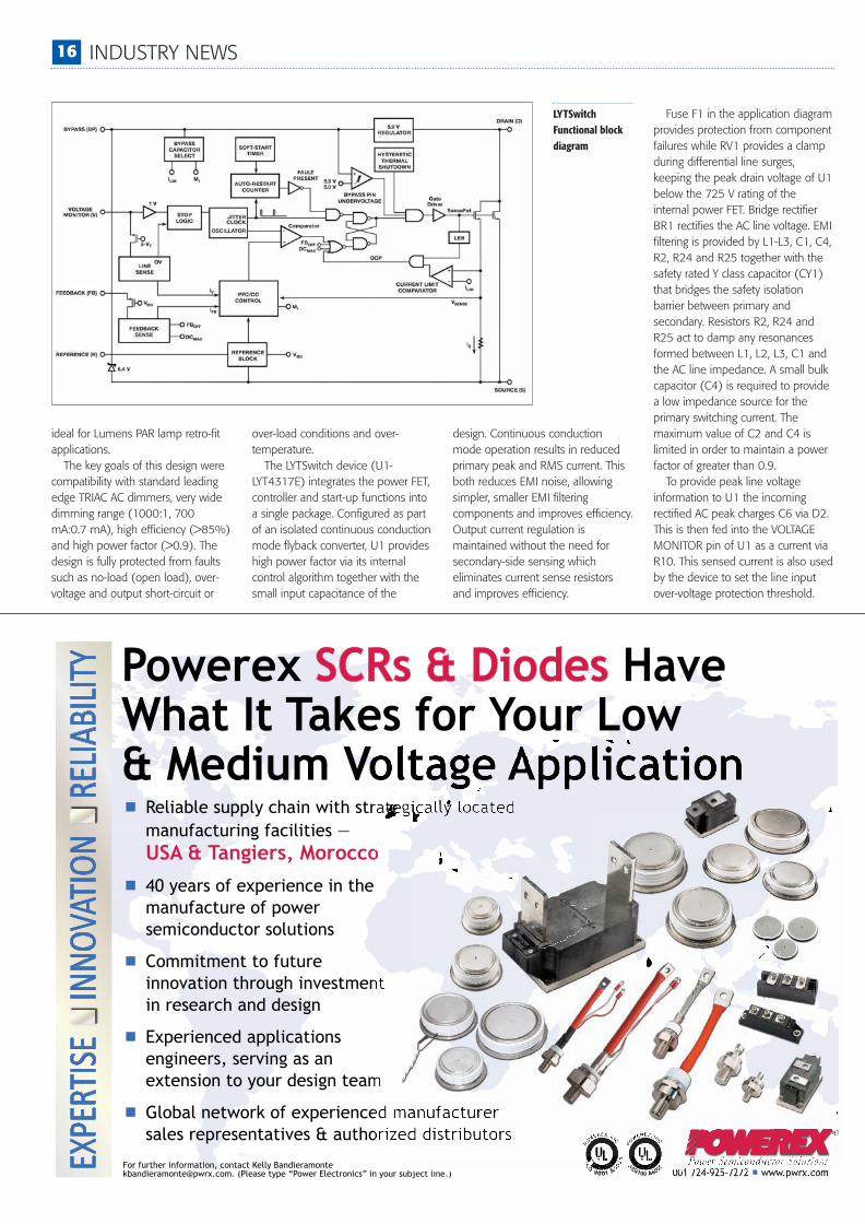
Dimmabledriver forHigh-PowerLEDsPower Integrations introduced itslatest family of LED-driver ICs, aimedat consumer, commercial andindustrial lighting applications. Thenew LYTSwitch™ IC family deliverstight regulation and high efficiencyfor tube replacements and high-baylighting, while providing exceptionalperformance in TRIAC-dimmablebulb applications.A LYTSwitch device monolithically
combines a controller and high-voltage power FET into one package.The controller provides both highpower factor and constant currentoutput in a single-stage. TheLYTSwitch controller consists of anoscillator, feedback (sense and logic)circuit, 5.9 V regulator, hystereticover-temperature protection,frequency jittering, cycle-by-cyclecurrent limit, auto-restart, inductancecorrection, power factor and constantcurrent control. The devices enableoff-line LED drivers with high powerfactor which easily meet internationalrequirements for total harmonicdistorsion (THD) and harmonics.Output current is tightly regulatedwith better than ±5% CC tolerance.Efficiency of up to 92% is easilyachieved in typical applications. Theturn-on characteristics enable driverswith a wide dimming range and faststart-up, even when turning-on froma low conduction angle.LYTSwitch ICs are highly integrated
and employ a primary-side control
technique that eliminates the opto-isolator and reduces componentcount. This allows the use of low-cost single-sided PCBs.Combining PFC and CC functions
into a single-stage also helps reducecost and increase efficiency. The 132kHz switching frequency permits theuse of small, low-cost magnetics.LED drivers using the LYTSwitchfamily do not use primary-sidealuminum electrolytic bulk
capacitors. This means extendeddriver lifetime, especially in bulb andother high-temperature applications.
Dimmable 25 W TRIAC LEDdriverThis design with the LYT4317E isalso configurable for non-dimmableapplications by simple componentvalue changes. It was optimized todrive an LED string at a voltage of 36V with a constant current of 0.7 A
LYTSwitch family ofLED-driver ICs
Industry News_New_Layout 1 29/11/2012 14:36 Page 15
16 INDUSTRY NEWS
ideal for Lumens PAR lamp retro-fitapplications. The key goals of this design were
compatibility with standard leadingedge TRIAC AC dimmers, very widedimming range (1000:1, 700mA:0.7 mA), high efficiency (>85%)and high power factor (>0.9). Thedesign is fully protected from faultssuch as no-load (open load), over-voltage and output short-circuit or
design. Continuous conductionmode operation results in reducedprimary peak and RMS current. Thisboth reduces EMI noise, allowingsimpler, smaller EMI filteringcomponents and improves efficiency.Output current regulation ismaintained without the need forsecondary-side sensing whicheliminates current sense resistorsand improves efficiency.
over-load conditions and over-temperature.The LYTSwitch device (U1-
LYT4317E) integrates the power FET,controller and start-up functions intoa single package. Configured as partof an isolated continuous conductionmode flyback converter, U1 provideshigh power factor via its internalcontrol algorithm together with thesmall input capacitance of the
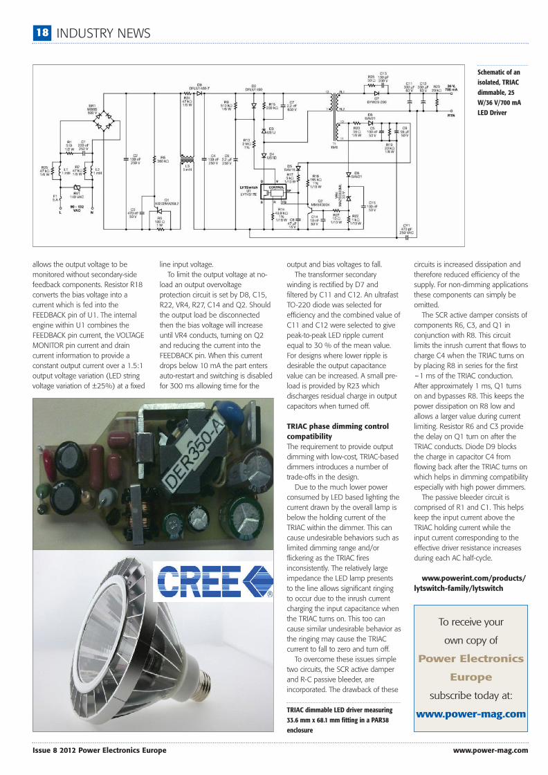
Fuse F1 in the application diagramprovides protection from componentfailures while RV1 provides a clampduring differential line surges,keeping the peak drain voltage of U1below the 725 V rating of theinternal power FET. Bridge rectifierBR1 rectifies the AC line voltage. EMIfiltering is provided by L1-L3, C1, C4,R2, R24 and R25 together with thesafety rated Y class capacitor (CY1)that bridges the safety isolationbarrier between primary andsecondary. Resistors R2, R24 andR25 act to damp any resonancesformed between L1, L2, L3, C1 andthe AC line impedance. A small bulkcapacitor (C4) is required to providea low impedance source for theprimary switching current. Themaximum value of C2 and C4 islimited in order to maintain a powerfactor of greater than 0.9.To provide peak line voltage
information to U1 the incomingrectified AC peak charges C6 via D2.This is then fed into the VOLTAGEMONITOR pin of U1 as a current viaR10. This sensed current is also usedby the device to set the line inputover-voltage protection threshold.
LYTSwitchFunctional blockdiagram
Industry News_New_Layout 1 29/11/2012 14:36 Page 16

INDUSTRY NEWS 17
www.power-mag.com Issue 8 2012 Power Electronics Europe
Resistor R9 provides a dischargepath for C6 with a time constantmuch longer than that of therectified AC to prevent generation ofline frequency ripple.
The VOLTAGE MONITOR pincurrent and the FEEDBACK pincurrent are used internally to controlthe average output LED current. ForTRIAC phase-dimming applications a49.9 kΩ resistor (R14) is used onthe REFERENCE pin and 2 MΩ
(R10) on the VOLTAGE MONITORpin to provide a linear relationshipbetween input voltage and theoutput current and maximizing thedimming range.
Diode D3, R15 and C7 clamp thedrain voltage to a safe level due tothe effects of leakage inductance.Diode D4 is necessary to preventreverse current from flowing throughU1 for the period of the rectified ACinput voltage that the voltage across
C4 falls to below the reflected outputvoltage (VOR).
Diode D6, C5, C9, R19 and R20create the primary bias supply froman auxiliary winding on thetransformer. Capacitor C8 provideslocal decoupling for the BYPASS pinof U1 which is the supply pin for theinternal controller. During start-up C8is charged to ~6 V from an internalhigh-voltage current source tied tothe device DRAIN pin. This allows
ComPack Family... Compact Package with highest power density
For more information pleaseemail [email protected] or call Petra Gerson: +49 6206 503249
600 A Phase-legs
Features
Applications
TYPE ITAVM VRRM
the part to start switching at whichpoint the operating supply current isprovided from the bias supply viaR17. Capacitor C8 also selects theoutput power mode (47 µF forreduced power was selected toreduce dissipation in U1 andincrease efficiency for this design).
The bias winding voltage isproportional to the output voltage(set by the turns ratio between thebias and secondary windings). This
PFC waveforms(left) and THD(light blue) of theLYTSwitch
Industry News_New_Layout 1 29/11/2012 14:37 Page 17
18 INDUSTRY NEWS
Issue 8 2012 Power Electronics Europe www.power-mag.com
allows the output voltage to bemonitored without secondary-sidefeedback components. Resistor R18converts the bias voltage into acurrent which is fed into theFEEDBACK pin of U1. The internalengine within U1 combines theFEEDBACK pin current, the VOLTAGEMONITOR pin current and draincurrent information to provide aconstant output current over a 1.5:1output voltage variation (LED stringvoltage variation of ±25%) at a fixed
line input voltage.To limit the output voltage at no-
load an output overvoltageprotection circuit is set by D8, C15,R22, VR4, R27, C14 and Q2. Shouldthe output load be disconnectedthen the bias voltage will increaseuntil VR4 conducts, turning on Q2and reducing the current into theFEEDBACK pin. When this currentdrops below 10 mA the part entersauto-restart and switching is disabledfor 300 ms allowing time for the
output and bias voltages to fall.The transformer secondary
winding is rectified by D7 andfiltered by C11 and C12. An ultrafastTO-220 diode was selected forefficiency and the combined value ofC11 and C12 were selected to givepeak-to-peak LED ripple currentequal to 30 % of the mean value.For designs where lower ripple isdesirable the output capacitancevalue can be increased. A small pre-load is provided by R23 whichdischarges residual charge in outputcapacitors when turned off.
TRIAC phase dimming controlcompatibilityThe requirement to provide outputdimming with low-cost, TRIAC-baseddimmers introduces a number oftrade-offs in the design.Due to the much lower power
consumed by LED based lighting thecurrent drawn by the overall lamp isbelow the holding current of theTRIAC within the dimmer. This cancause undesirable behaviors such aslimited dimming range and/orflickering as the TRIAC firesinconsistently. The relatively largeimpedance the LED lamp presentsto the line allows significant ringingto occur due to the inrush currentcharging the input capacitance whenthe TRIAC turns on. This too cancause similar undesirable behavior asthe ringing may cause the TRIACcurrent to fall to zero and turn off.To overcome these issues simple
two circuits, the SCR active damperand R-C passive bleeder, areincorporated. The drawback of these
circuits is increased dissipation andtherefore reduced efficiency of thesupply. For non-dimming applicationsthese components can simply beomitted.The SCR active damper consists of
components R6, C3, and Q1 inconjunction with R8. This circuitlimits the inrush current that flows tocharge C4 when the TRIAC turns onby placing R8 in series for the first~1 ms of the TRIAC conduction.After approximately 1 ms, Q1 turnson and bypasses R8. This keeps thepower dissipation on R8 low andallows a larger value during currentlimiting. Resistor R6 and C3 providethe delay on Q1 turn on after theTRIAC conducts. Diode D9 blocksthe charge in capacitor C4 fromflowing back after the TRIAC turns onwhich helps in dimming compatibilityespecially with high power dimmers.The passive bleeder circuit is
comprised of R1 and C1. This helpskeep the input current above theTRIAC holding current while theinput current corresponding to theeffective driver resistance increasesduring each AC half-cycle.
www.powerint.com/products/lytswitch-family/lytswitch
Schematic of anisolated, TRIACdimmable, 25W/36 V/700 mALED Driver
TRIAC dimmable LED driver measuring33.6 mm x 68.1 mm fitting in a PAR38enclosure
To receive your
own copy of
Power Electronics
Europe
subscribe today at:
www.power-mag.com
Industry News_New_Layout 1 29/11/2012 14:37 Page 18

SKiiP®4Most powerful IPM on the market
From 500 kW to 2.1 MW
2 – 3 times higher power cycl ing capabil ity
Sintered chips, no solder fatigue
temperature sensorIntegrated current, voltage and
, semiconductor & cool ing: dr iver13 in
2 – 3 times higher power cycl ing capabil ity
Sintered chips, no solder fatigue
Integrated current, voltage and
, semiconductor & cool ing
19_PEE_0812_Layout 29/11/2012 14:12 Page 1

20 INDUSTRY NEWS
Issue 8 2012 Power Electronics Europe www.power-mag.com
LED Driver with FrequencySynchronization and PWMDimmingTI’s new TPS92510 is a 60-V, 1.5-A, buckregulator with an integrated high-side N-channelMOSFET. To improve performance during line andload transients the device implements a constantfrequency, peak-current mode control whichreduces output capacitance and simplifies externalfrequency compensation design. The wideswitching frequency of 100 kHz to 2500 kHzallows for efficiency and size optimization whenselecting the output filter components. Togetherwith TI’s WEBENCH® LED Architect, the lightingdeveloper can quickly design a powermanagement circuit to drive a string of up to 17high-brightness LEDs at up to 97 percent powerefficiency in automotive, industrial and generalillumination applications.The TPS92510 integrates a thermal foldback
feature that reduces the average output current toensure that the sensed LED temperature neverexceeds a specific value, improving the reliabilityof the overall system. An integrated frequencysynchronization feature allows a reduction ofunwanted beat-frequencies in multi-stringapplications and simplifies EMI filtering. Theadjustable input voltage UVLO featureaccommodates the various deep discharge levelsof multiple battery types.The TPS92510 includes also cycle-by-cycle
over-current protection, and thermal shutdownprotection. It is available in a 10-pin MSOPPowerPADTM package.
Start-up procedureThe VIN and EN UVLO conditions must besatisfied before the TPS92510 is allowed toswitch. When the EN pin (see functional blockdiagram) is held low the device enters a low-power shutdown mode, and some internal circuitsare deactivated to conserve power. When ENreturns high these circuits are enabled, whichresults in a delay of approximately 50 s (typical)before switching starts. During start-up theTPS92510 operates in a minimum pulse widthmode, which is an open-loop control. At the startof each switching cycle the internal oscillatorinitiates a SET pulse. The high-side MOSFET turns on with a
minimum pulse width of 300 ns (typical),independent of the COMP voltage. The devicedoes not pulse skip. While operating in minimumpulse width mode the LED bypass capacitor (seesimplified application diagram) is being charged,causing an in-rush current. Also, the COMPvoltage begins to rise as the error amplifier outputcurrent charges the compensation network. When
the COMP voltage reaches approximately 0.7 V,the error amplifier is ensured to be out ofsaturation and to have sufficient gain to regulatethe loop. The TPS92510 then transitions fromminimum pulse width mode to regulation mode.During regulation mode the error amplifier is nowin closed-loop control of the system. The gain ofthe error amplifier quickly increases the duty cycle,
which causes the output voltage to increase. Oncethe output voltage approaches the forward voltageof the LED string the LED current quickly begins toincrease until it reaches regulation.
The TPS92510 is designed to output aminimum pulse width during each switching cycleof 280 ns (typical). The control loop cannotregulate the system to an on-time less than this
TPS92510 functional block diagram
Industry News_New_Layout 1 29/11/2012 14:47 Page 20

21_PEE_0812_Layout 29/11/2012 14:15 Page 1

22 INDUSTRY NEWS
Issue 8 2012 Power Electronics Europe www.power-mag.com
amount, and it does not skip pulses. Whenattempting to operate below the minimum on-time the system loses regulation and the LEDcurrent increases.The device is enabled when the VIN pin voltage
is above 2.5 V and when the EN pin voltage isabove 1.25 V. The VIN pin voltage threshold hasno hysteresis. The EN pin has an internal pull-upcurrent source, I1, of 0.9 A that provides adefault ON state when the EN pin is floating.Once the EN pin voltage exceeds 1.25 V, anadditional 2.9 A of hysteresis, IHYS, is added.This additional current provides some inputvoltage hysteresis. Via an adjustable, fixed-frequency, peak current
mode control, at each switching cycle an internaloscillator initiates the turn-on of the MOSFET. TheLED current flows through the sense resistor anddevelops the feedback voltage on the VSENSEpin. The error amplifier output (COMP pin) iscompared to the high-side MOSFET current. Whenthe MOSFET current reaches the level set by theCOMP pin voltage the MOSFET is turned off. The switching frequency is adjustable over a
wide range from approximately 100 kHz to 2500kHz by placing a resistor on the RT/CLK pin. TheRT/CLK pin voltage is typically 0.5 V and musthave a resistor to ground to set the switchingfrequency. To reduce the solution size onetypically sets the switching frequency as high aspossible, but trade-offs of the supply efficiency,
maximum input voltage and minimumcontrollable on time should be considered. Theminimum controllable on time limits themaximum operating input voltage.The RT/CLK pin can be used to synchronize the
regulator to an external system clock byconnecting a square wave to the RT/CLK pinthrough the circuit network. The square waveamplitude must transition lower than 0.5 V andhigher than 2.2 V on the RT/CLK pin and have anon-time greater than 40 ns and an off-timegreater than 40 ns. The synchronization frequencyrange is 300 kHz to 2200 kHz. The rising edge ofthe PH is synchronized to the falling edge of
RT/CLK pin signal. The external synchronizationcircuit default frequency is set by connecting theresistor from the RT/CLK pin to ground should thesynchronization signal turn off. The TPS92510 incorporates a PWM dimming
input pin, which directly controls theenable/disable state of the internal gate driver.When PDIM is low, the gate driver is disabled. ThePDIM pin has a 1-A pull-up current source,which creates a default ON state when the PDIMpin is floating. When PDIM goes low and the gatedriver shuts off, and the LED current quicklyreduces to zero. During the PDIM off-time theCOMP voltage of the sample-and-hold switch on
Simplifiedapplicationdiagram
Drives and ControlsExhibition and Conference 2014
The UK’s leading exhibition for Drives, Automation, Power Transmission and Motion Control Equipment
8-10 APRIL 2014 NEC BIRMINGHAM
visit www.drives-expo.com ...The Perfect Fit
ContactDoug Devlin on:t: 01922 644766 m: 07803 624471 e: [email protected]
Industry News_New_Layout 1 29/11/2012 14:47 Page 22

INDUSTRY NEWS 23
www.power-mag.com Issue 8 2012 Power Electronics Europe
the error amplifier output remains unchanged.Also, the error amplifier output is internallyclamped low. These techniques help the systemrecover to its regulation duty cycle quickly.The TPS92510 is designed to operate up to
100% duty cycle as long as the BOOT to PHvoltage is greater than 2.1 V. If the BOOT capacitorvoltage drops below 2.1 V, then the BOOT UVLOcircuit turns off the MOSFET, which allows theBOOT capacitor to be refreshed. The currentrequired from the BOOT capacitor to keep theMOSFET on is quite low. Therefore, manyswitching cycles occur before the BOOT capacitoris refreshed. In this way, the effective duty cycle ofthe converter is quite high.Attention must be taken in maximum duty
cycle applications which experience extendedtime periods with little or no load current. Whenthe voltage across the BOOT capacitor falls belowthe 2.1 V UVLO threshold, the high-side MOSFETis turned off, but there may not be enoughinductor current to pull the PH pin down torecharge the BOOT capacitor. The high-sideMOSFET of the regulator stops switching becausethe voltage across the BOOT capacitor is less than2.1 V. The output capacitor then decays until thedifference between the input voltage and outputvoltage is greater than 2.1 V, at which point theBOOT UVLO threshold is exceeded, and thedevice starts switching again until the desiredoutput current is reached. This operating conditionpersists until the input voltage and/or the loadcurrent increases. It is recommended to adjust theVIN stop voltage greater than the BOOT UVLO
trigger condition at the minimum load of theapplication using the adjustable VIN UVLO featurewith resistors on the EN pin.A thermal foldback protection has been
implemented to limit the LED temperature incase of a system failure, such as an incorrectlyprogrammed LED current, a poor thermal designor increasing thermal impedance over time. A100-A current source generates a voltageacross an NTC resistor that is located near theLED load. When the NTC voltage drops below 2V at the TSENSE pin (due to excessive LEDtemperature) the device begins to modulate theconverter at a frequency of 5.9 kHz. The morethe NTC voltage drops, the longer the off-timeof the converter. Therefore, the delivered outputpower is reduced until the NTC cools, theTSENSE voltage (VTSENSE) increases, and thesystem no longer requires reduced outputpower. The thermal foldback protection slowlyreduces the output power, as a function of thethermal time constant. Thermal foldbackprotection is intended for protection only. It isnot intended to be used as a regulation feature.During thermal foldback the error amplifieroutput is internally clamped low, and the COMPsample-and-hold switch is open, preserving theCOMP pin voltage.When the TPS92510 junction temperature
reaches 150°C, the driver immediately disablesthe high-side MOSFET. The COMP sample-and-hold switch closes, and the COMP pin internallyclamps low until the junction temperature dropsby approximately 20°C. At this time, the COMP
clamp is removed and the driver attempts toregulate.
LED fault protection mechanismsAn open circuit can be the result of an open LEDor an open wire connection. In either case, thevoltage at the VSENSE pin becomes zero, andthis causes the COMP pin voltage to rise,commanding wide duty cycles. The outputvoltage eventually rises to the input voltage. Thisis a safe operating mode, provided that theoutput capacitors are rated for the input voltagepotential.As shown in the output voltage clamp
schematic, a transient voltage suppressor (TVS)device from VOUT to GND, or a diode from VOUTto the VIN pin can be used to clamp the L-Cresonant output voltage ringing caused by theinductor and the output capacitor at the momentthe LED string opens, particularly at high-inputvoltage and high-output voltage operatingconditions. The TVS should have a voltage ratinggreater than the maximum output voltage, so thatit does not conduct under normal operation.Either of these devices can be used to limit theoutput voltage to safe levels during an open LEDfault.If the current sense resistor also opens, current
attempts to flow into the ESD structure of theVSENSE pin. To prevent damage to the device, aseries resistor (RESD) on the VSENSE pin can beused to limit this current. The VSENSE pin has aninternal, 8-V clamp, and the continuous currentshould be limited to a maximum of 20 mA.An external overvoltage protection circuit
consisting of VZ and RZ shown in the outputvoltage limiter, can be applied to the VSENSE pinto regulate the output voltage to less than theinput voltage potential.Some LEDs fail to a shorted state. It is unlikely
that multiple LEDs fail short simultaneously. If abypass capacitor is in parallel with the LED string itis charged to the LED string forward voltage.When one or more LEDs instantaneously short,the bypass capacitor senses a voltage transientfrom the initial LED string voltage to somethingless, depending on the number of LEDs that arenow shorted. The voltage change across thecapacitor causes the capacitor to discharge someenergy in the form of a transient current throughthe LED string. This current flows from the bypasscapacitor through the LED string, but not throughthe current sense resistor. Therefore, theTPS92510 does not sense the fault event, anddoes not respond to it. The peak transient currentis a function of the change in forward voltage dueto the shorted LED(s), and the dynamic resistanceof the LED string at the moment the short occurs.This current can be substantial, and may require aprotection circuit, unless the LEDs can survive thetransient current. After the LED has shorted theerror amplifier continues to regulate theprogrammed LED current at the new, loweroutput voltage.
www.ti.com/tps92510-pr-eu
Output voltage clampcircuitry
Output voltagelimiter circuitry
Industry News_New_Layout 1 29/11/2012 14:47 Page 23

24_PEE_0812_Layout 29/11/2012 14:16 Page 1

www.linear.com/products/LTC6804 BATTERY MANAGEMENT 25
www.power-mag.com Issue 8 2012 Power Electronics Europe
Highly Accurate Hybrid/ElectricBattery MonitorLithium-Ion batteries require considerable care if they are expected to operate reliably over a long period.They cannot be operated to the extreme end of their state-of-charge (SOC). The capacity of Lithium-Ioncells diminish and diverge over time and usage, so every cell in a system must be managed to keep itwithin a constrained SOC. Linear Technology’s 3rd generation Battery Management System provides manydesirable features for monitoring large and distributed battery packs in vehicle and industrial applications, asoutlined by Greg Zimmer, Product Marketing Engineer at Linear Technology Corporation.
To provide sufficient power for a vehicle,tens or hundreds of battery cells arerequired. These cells must be configuredin a long series; as much as 1000 V andhigher. The battery electronics mustoperate in this very high voltageenvironment and reject common modevoltage effects, while differentiallymeasuring and controlling each cell inthese strings. The electronics must be ableto translate information from the batterystack to a central point for processing(Figure 1).On top of these requirements, operating
a high-voltage battery stack in a vehicle orother high-power applications imposes
tough conditions, such as operation withsignificant electrical noise and wideoperating temperatures. The batterymanagement electronics are expected tomaximize operating range, lifetime, safetyand reliability, while minimizing cost, sizeand weight.
Requirements of the batterymanagement electronicsThe electronic system that measures andmanages the battery stack (also known asthe BMS) has three key requirements: The BMS must know the health of eachbattery cell in the stack. Primarily, this isaccomplished by estimating the State-of-Charge of each cell in the battery system.The current SOC can be combined withhistorical information for determining thestatus of each cell.
The BMS must control the state-of-chargefor each cell in a system. This is done bycontrolling the charge, discharge andbalancing of each cell in a system.
Ensure safety. The BMS must know theelectronics are properly working such that
the battery info is valid. The golden rule is“no over voltage cell can appear as anOK voltage cell“. In order to do this, theBMS has to communicate the status ofall cells and the BMS electronics to therest of the system. The key element in the battery
management electronics is the batterymonitor IC. The battery monitor performsthe difficult task of accurately measuring thevoltage, current, and temperature of eachcell and passing the data to a control circuit.A controller then uses the cell data tocompute the state of charge and state ofhealth of the pack. The controller maycommand the battery monitor to charge ordischarge certain cells to maintain abalanced state of charge within the pack.
Third generation BMSThe LTC®6804 (Figure 2) is a high voltagebattery monitor can measure up to 12series connected battery cells at voltagesup to 4.2 V, with 16 bit resolution and lessthan 0.04 % maximum measurementerror. High precision is maintained over
Figure 1: Forachieving highvoltages anumber of cellshave to beconnected inseries and eachcell requires adifferentialmeasurementof its state-ofcharge
Figure 2: The LTC6804 measures 12 battery cells (LiIon, NiMh, Supercaps) with high accuracy in 290 microseconds
Linear_Feature_Layout 1 29/11/2012 14:54 Page 25

26 BATTERY MANAGEMENT www.linear.com/products/LTC6804
Issue 8 2012 Power Electronics Europe www.power-mag.com
time, temperature and operating conditionsby a sub-surface Zener voltage reference,similar to references used in precisioninstrumentation. When stacked in series,the LTC6804 enables the measurement ofevery battery cell voltage in large highvoltage systems, within 290 µs. Sixoperating modes are available to optimizeupdate rate, resolution and the low passresponse of the built-in 3rd order noisefilter. In the fastest mode, all cells can bemeasured within 290 µs.Multiple LTC6804s can be
interconnected over long distances andoperated simultaneously, using proprietary2-wire isoSPI interface. This interfaceprovides high RF noise immunity up to 1Mbps data rate and up to 100 meters ofcable, using only a twisted pair of wires.Two communication options are available:With the LTC6804-1, multiple devices areconnected in a daisy chain with one hostprocessor connection for all devices; Withthe LTC6804-2, multiple devices areconnected in parallel to the host processor,with each device individually addressed.The LTC6804 was designed to minimize
power consumption, especially during longterm storage where battery drain isunacceptable. In sleep mode, less than 4µA from the battery are drawn, andbecause the supply pin can beindependently disconnected, batterycurrent can be reduced to less than 1 µA. General purpose I/O pins are available
to monitor analog signals, such as currentand temperature, and can be capturedsimultaneously with the cell voltagemeasurements. Additional features includepassive balancing for each cell with aprogrammable balancing timer for up to 2hours, even in sleep mode. The LTC6804can also interface with external I?C devices,such as temperature sensors, ADCs, DACsor EEPROM. Local EEPROM can be usedto store serialization and calibration data to
enable modular systems.The LTC6804 was designed to surpass
the environmental, reliability and safetydemands of automotive and industrialapplications. It is fully specified for operationfrom -40°C to 125° and has beenengineered for ISO 26262 (ASIL) compliantsystems and a full set of self-tests ensurethat there are no latent fault conditions. Toaccomplish this, the device includes aredundant voltage reference, extensive logictest circuitry, open wire detection capability, awatchdog timer and packet error checkingon the serial interface.
Impact of measurement accuracyLi-Ion cells generally have a flat dischargecurve, with only a few millivolts ofdifference for each percentage of change inSOC (Figure 3). Because of this, the cellvoltage measurement error directlytranslates into a limitation of the usableSOC range of operation. At a typical cost of$ 600 per kilowatt-hour today, a typical 16kWh battery pack represents a significantportion of an electric vehicle’s cost, andputs intense demand on achieving the bestpossible measurement accuracy. Typically, in today’s battery monitoring
ICs, the voltage reference contributes thelargest amount of error to cellmeasurement: The sources of error comefrom the initial accuracy, temperature drift,thermal hysteresis and long term drift.Hysteresis refers to an offset voltageinduced in the reference when thermallycycled. The most significant thermal eventoccurs during the solder process.The current generation of battery
monitors relies on band gap voltagereferences. Band-gap references havegained in popularity in the last decadebecause of their low power, low dropoutvoltage and small size. However, the band-gap reference voltage is sensitive tomechanical stress. Mechanical stress is
induced in an integrated circuit from theexpansion and contraction of the plasticpackage and the copper lead framethrough mechanical strain, humidity, andtemperature. As an example, during PCBassembly the electronics experience severalthermal shocks from the soldering processand a voltage reference can experiencethermal hysteresis.Precision is maintained over time,
temperature and operating conditions by asub-surface Zener voltage reference, similarto the type of voltage reference used inprecision instrumentation (see Figure 3).Our test results show that the LTC6804thermal hysteresis is at least 5x better thanother parts, including our own LTC6802and LTC6803.
Advantage of the Delta Sigma ADCThe measurement accuracy is alsobolstered by dual 16-bit ADCs. With aresolution of 100 µV, the LTC6804 canmeasure all battery cells in the systemwithin 290 µs. General purpose I/O signalsare also available to measure externalanalog signals. The specified measurementrange is from 0 to 5 V, accommodating awide range of battery chemistries, includingLithium-Ion, NiMH and super capacitors. The battery stack measurement
electronics need to be designed in thecontext of the automobile or high-powersystem in which it will be used. Thesystems typically generate significantelectrical noise and transients frominverters, actuators, switches, relays, etc.This noise has to be removed via pre-filtering, ADC filtering, or post processfiltering. An RC filter at each cell input is asimple, effective way to reduce somenoise, but not nearly enough to reduce thenoise prevalent in most battery systems.There is a trade-off with RC filtering– inputresistance can create IR errors on themonitor input, and also significantly slowdown the signal of interest. For example, foran RC to offer significant attenuation at 10kHz, a roll off at 160 Hz or lower is needed.Adding active filtering on each channel isexpensive and impractical. Post processingis generally not practical for a large batterystack, where a large number of samplesneed to be downloaded from a long seriesof battery cells. As a compromise, sampleaveraging within the battery monitor ispossible; however, this provides only amodest amount of filtering.Linear Technology’s battery monitor ICs
use delta-sigma ADCs, rather than themuch faster SAR type converter. Ourdesigners recognized that a fast acquisitionwas useless if system noise swamped thesignal. Delta-Sigma converters have built-in,high order, low pass filtering. To leveragethis feature, the LTC6804 was designed withFigure 3: Discharge characteristics of a LiIon battery at 25°C
Linear_Feature_Layout 1 29/11/2012 14:54 Page 26

www.linear.com/products/LTC6804 BATTERY MANAGEMENT 27
www.power-mag.com Issue 8 2012 Power Electronics Europe
six user programmable ADC speeds. Thisallows the user to choose the best filteringand ADC speed combination for theirsystem. At its highest speed, all cells in thehigh voltage stack can be measured within290 µs. The slow ADC setting with a cutofffrequency of 26 Hz can be used toeliminate EMI for periodic calibration.
Distributed battery packs supportedTo accommodate the large quantity of cellsfor high powered systems, the batteriesmay need to be divided into packs, anddistributed throughout available spaces inthe vehicle. With 10 to 24 cells in a typicalmodule, a modular design allows for abattery pack to be used as a building blockacross all platforms; a modular designsimplifies maintenance and warranty issues,and can be used as the basis for very largebattery stacks. It allows battery packs to bedistributed over larger areas for moreeffective use of space.The LTC6804 was designed with
several features to support a modulardesign. First, the GPIO can be configuredto operate as a SPI or I2C Port. Thisallows the device to interface to localEEPROM, where serialization andcalibration data can be stored. Once amodule has been built, the electronics toremain connected and the LTC6804 canstay in a sleep mode, using less than 4µA. This ensures that there is no
appreciable battery drain, or unbalancingof battery cells, even after months oryears of storage. Each module can bestored as an independent pack, ready tobe used as needed. Finally, the isoSPIinterface provides a method forinterconnecting modules, even withsignificant distance from pack to pack.To support a distributed, modular
topology with high electromagneticinterference (EMI), a robustcommunication system, is required. Mostcommonly, this is achieved with an isolatedCAN interface, requiring a microprocessor,digital isolator and CAN transceiver. TheLTC6804 eliminates the cost and softwarecomplexity of CAN by including a built-inisoSPI interface. The isoSPI combined witha simple transformer allows for data up to1 Mbps to be communicated over longdistances using only a twisted pair cable.This allows data transfer between modulesand the LTC6804 is available with 2interconnection options. Using theLTC6804-1, multiple devices are connectedin a daisy-chain with one host processorconnection for all devices. Using theLTC6804-2, multiple devices are connectedin parallel to the host processor, with eachdevice individually addressed. The signal strength of the isoSPI pulses
and the impedance of the 2-wireconnection are adjustable. The user canincrease signal current by changing resistor
values. This flexibility means that the isoSPIbus can be tailored for communication over100 meters of cable and reject highinterference levels. The LTC6804 includes a15-bit cyclic redundancy check (CRC) toensure the integrity of the data. The performance of isoSPI has been
confirmed with Bulk Current Injection (BCI)testing. BCI measures systems immunity toelectromagnetic interference. RF energy isinjected through a probe clamped aroundthe cable while another probe measuresthe resulting RF current. Data is sentthrough the cable and the CRC is analyzedfor data corruption. The test is repeatedwith several strengths of isoSPI data pulses.The 20 mA isoSPI data pulses are immuneto 200 mA of RF injection.
Cell balancing controlControlling the SOC for each cell in asystem requires balancing each cell in thesystem. Balancing refers to adding orremoving charge on individual cells, asneeded, to keep each within a controlledSOC range. Passive balancing, which isprimarily used today, involves dischargingany cell that reaches its maximum State-of-Charge limit during the charge process.This allows the rest of the cells in a string tocontinue being charged without damagingthis weaker cell. This extends the amountof charging and allows more of the fullcapacity of each cell. The LTC6804includes onboard FETs that can providemodest passive balancing, or can controlexternal power FETs for higher currentpassive balancing. Passive balancing is energy inefficient
and relatively slow. Typical balancingcurrents range from 1 to 5 % of the cellcapacity. To dissipate 10 % of the chargefrom a 40 Ah battery requires 10 hours atI=400 mA, or generates 8 W of heat percell at I=2 A. For large capacity packs, thebalancing time or heat generation canbecome unacceptable; a high efficiency,high current active balancer may be theonly viable solution. Active balancing refersto moving charge between cells, bothduring the charge and discharge cycles, tokeep the SOCs within range. This canextend both the charge and dischargephases, allowing for further extension of theusable battery capacity. It also has thepotential to reduce heat generation, reducebattery charging time, increase energyefficiency and extend the life of the cells(by ensuring cells age in unison).New IC’s are anticipated in the near
future, such as Linear Technology’sLTC3300 with balancing currents up to 10A. The LTC3300 can be controlled via aserial port on the LTC6804, offering anaccurate, easy to use cell monitor andbalancing system (Figure 5).
ABOVE Figure 4: TheLTC6804-1 (left) connectsmultiple devices are in adaisy-chain while theLTC6804-2 connectsmultiple devices in parallelto the host processor
LEFT Figure 5:Bidirectional activebalancing controlled withthe LTC6804 SPI interface
Linear_Feature_Layout 1 29/11/2012 14:54 Page 27

28 BATTERY MANAGEMENT www.linear.com/products/LTC6804
Issue 8 2012 Power Electronics Europe www.power-mag.com
Charge and discharge cycles have an impact on the longevity oflithium ion batteries used in electric vehicles and theultracapacitors used for energy storage in photovoltaic systems. Forthis reason, it is necessary for battery safety and longevity to beable to establish the state of charge (SoC) and the state offunction (SoF). As electric mobility becomes more popular, morevendors are entering the market. At Electronica Maxim Integrated Products
(www.maximintegrated.com) introduced the MAX17823, ahigh-voltage battery sensor for mission-critical automotive andindustrial LiIon battery and fuel cell applications. Offering a suite ofproprietary integrated ISO-26262 diagnostic features, theMAX17823 maximizes electric and hybrid electric vehicle drivingrange while ensuring battery and fuel cell safety and reliability.A proprietary, differential UART communications link (5 m) is
automotive EMC-hardened, enabling uninterrupted cell monitoringduring battery pack service disconnect and eliminating costly digitalisolators. An innovative shutdown feature safely enters all daisy-chain devices into sleep mode when a host microcontroller loses12V power. ASIL-D (Automotive Safety Integrity Level “D”, per ISO-26262) compliance is achieved and maintaines accurate 96-cell,100 measurements-per-second performance. The 96-cell hot-plugimmunity ensures highest reliability during battery managementsystem manufacturing.
ARM CortexTM-M32 core and compliant with functional safetylevels (IEC61508 / ISO26262). Sample shipments of this chipset will start in February 2013,
and mass production in April 2014. The company will prepare asoftware library to be compliant with the IEC61508 and ISO26262functional safety standards and is also planning reference models.These tools will simplify the implementation of battery monitoringsystems.
More Battery Management Systems
Also Toshiba Electronics Europe (www.toshiba-components.com) has announced it will launcha LiIon battery monitor chipset for automotive applications. Designed for Hybrid Electric Vehicles (HEVs) and Electric
Vehicles (EVs), the Li-ion battery chipset monitors up to 16 cellsand comprises the TB9141FG monitoring IC and theTMPM358FDTFG microcontroller. The chipset detects remainingbattery level, equalizes battery levels (cell balancing) and candetect abnormal battery status. Typical measurement accuracy is±2mV cell voltage, improving the accuracy of battery state ofcharge (SOC) detection and contributing to more effective batteryusage. The TB9141FG incorporates a cell balance switch and isable to measure battery voltage while cell balancing. Furthermore, the TB9141FG is able to communicate in a noisy
environment by differential signals using daisy chaincommunication with neighbouring TB9141FGs. TheTMPM358FDTFG is a 32-bit RISC microcontroller built around an
Maxim‘s high-voltage battery sensor manages 96 cells
Isabellenhütte (www.isabellenhuette.de) offers for LiIon batterymanagement the tried-and-trusted IVT sensor module formeasuring current, voltage and temperature, which is nowavailable in a modular design enabling customers to selectindividual components and configure their own made-to-measureIVT in accordance with their specific needs. A customer mightchoose communication between SPI or CAN interfaces, between asensor module with or without galvanic separation or many otherconfiguration possibilities. As well as the current input, up to threevoltage inputs are possible; these can be fitted with input filters.Likewise, customers can choose from three different powersupplies. The IVT can be equipped with an optional overcurrentdetection facility. As well as the off-the-shelf products, customerscan order specific solutions upon request. Current range is up to1,500 A, extended up to 5,600 A with 0.1 % tolerance.
Shunt-based battery measurement system for high currents
Chipset for monitoring 16 LiIon battery cells
Linear_Feature_Layout 1 29/11/2012 14:54 Page 28

www.apec-conf.orgwww.apec-conf.org
SPONSORED BY
2013March 17–21, 2013
Long Beach Convention Center
Long Beach, CA
THE PREMIER
GLOBAL EVENT
IN POWER
ELECTRONICSTM
THE PREMIER
GLOBAL EVENT
IN POWER
ELECTRONICSTM
Visit the APEC 2013
web site for the latest
information!
29_PEE_0812_Layout 29/11/2012 14:17 Page 1

30 POWER SEMICONDUCTORS www.infineon.com/trenchstop5
Issue 8 2012 Power Electronics Europe www.power-mag.com
High-Speed TRENCHSTOP 5 IGBTIGBTs are historically known for having long tail currents with focus on drive applications and anythingswitching up to 30 kHz was known as “High Speed”, where conduction losses were penalized to getswitching losses down. In 2008, Infineon launched a ground breaking technology called the HighSpeed3,which is the highest efficiency IGBT capable of switching up to 100 kHz with a MOSFET-like turn-offswitching behavior. Now Infineon’s TRENCHSTOP™ 5 technology is capable of switching well beyond 100 kHz. Mark Thomas, Discrete IGBT Product Marketing, Infineon Technologies AG, Villach, Austria
The TRENCHSTOP™5 technology is anoptimization of the TRENCHSTOP™concept combining Trench gate and FieldStop structures. In order to minimize totalpower losses, the chip thickness isreduced to 50 µm and an optimization ofthe carrier profile has been carried out toprovide a reduction of charge carrierswithin the drift zone that have to beremoved during the turn-off phase. Thesetwo measures allow for a significantreduction in conduction losses (VCE(sat))and turn-off switching losses (Eoff).Despite the chip thickness reduction, a650 V blocking capability is achieved, 50V higher than the previous generation.Additionally, thanks to a new transistorstripe cell structure the gate charge (Qg) isreduced and current density is increased. The combination of all the above
mentioned innovations result in an IGBTwith the lowest combination ofconduction losses (VCE(sat)) and totalswitching losses (Ets), thus producing thehighest efficiency IGBT.TRENCHSTOP 5 is the name for the
base technology and from this two devicefamilies are being initially released toaddress different application requirementsand fulfill designers’ needs. The designerhas the opportunity to select between theHighSpeed5 (H5) and HighSpeed5 Fast(F5) versions. The H5 family ischaracterized by an optimized field-stopdesign and is aimed to complement theHighSpeed3 IGBT family; it allows for the“plug-and-play” replacement of IGBTswithout any special effort in adjusting theboard design. It provides soft voltage riseduring hard commutation at turn-off evenwith low gate resistor (Rg) values andvery high di/dt.The F5 meanwhile, is the extended
performance solution. It provides higherefficiency, but more design effort is
required to harvest the benefits. Thedriver stage should be equipped with splitturn-on (Rg,on)/ turn-off (Rg,off) gateresistors to maximize efficiency andcontrol voltage overshoot during turn-off.It is the best fit for optimized PCB designwith low stray inductance both in thecommutation loop and packages andused in combination with Silicon Carbidediodes (SiC)
Comparison with Infineon’sHighSpeed3 Technology Compared to the HighSpeed3 (HS3)family, the TRENCHSTOP 5 shows asignificant improvement in all static anddynamic parameters. It provides * 50 V higher blocking voltage to allow
for bus voltage increases withoutcompromising reliability. Also for solarapplications, cosmic radiation robustnessin increased, 250 mV lower conduction losses(Vce(sat)) and a factor of 2 lower turn-on/-off switching losses (Eon and Eoff),resulting in the highest efficiency highspeed IGBT ever released,
drastic reduction of Coss, Cres ensuresbenchmark light load efficiency,
50% reduction in gate charge (Qg)allows for lower power driver ICs to beused without sacrificing performanceand enables a system cost reduction.Mild positive temperature coefficient of
the conduction and switching lossesmean efficiency is not sacrificed whendevices are driven with higher junctiontemperatures and thermal run awayduring paralleling is not a problem. The TRENCHSTOP 5 uses the new
Rapid Silicon diode as the free-wheelingdiode (FWD), which offers 50 ns reverserecovery time (trr) and temperature stableforward voltage (VF). This ensures turn-onlosses are minimized and overall
efficiency is optimized.
Dynamic behaviorIn order to highlight a new technology it isimportant to explain the gate resistorcontrollability of the switching behavior. Onthe left hand side of Figure 1, the turn-offcontrollability as function of Rg during astandard double pulse test circuit ishighlighted, with stray inductance of 45 nHin the commutation loop. The Eoff curve ofboth H5 and F5 are drastically lowercompared to traditional fast IGBTs, and inthe same range of Superjunction MOSFETsat low Rg of 5 Ω.The right hand plot of Figure 1 shows
the collector-emitter voltage at turn-off asfunction of Rg. The plot helps to underlinethe difference between H5 and F5, thusthe need for the two families. The H5shows a smooth switching behavior, withvoltage overshoot of the same order as theHighSpeed 3. The F5 meanwhile, ischaracterized by higher voltage overshootat turn-off, but exhibits higher efficiency.The typical waveforms are also shown inFigure 2, where the F5 shows much fastercurrent drop during turn off, translatingunavoidably in higher voltage overshoot(L*di/dt).Figure 3 shows the relationship between
the turn-on losses (Eon) and turn-on gateresistor value (Rg,on) for both F5 and H5.From Figure 3 it can be seen that theTRENCHSTOP 5 shows very similarbehavior to a superjunction MOSFET ofequivalent rating, and significantly lowerlosses compared to previous IGBTs. It canalso be concluded that the turn-onbehavior of the F5 and H5 is controllablevia the turn-on gate resistor (Rg,on) over awide range.What can be concluded from Figures 3,
4 and 5 is as follows: Two families are required to provide
Infineon_Feature_Layout 1 29/11/2012 14:57 Page 30

www.infineon.com/trenchstop5 POWER SEMICONDUCTORS 31
www.power-mag.com Issue 8 2012 Power Electronics Europe
designers with either an IGBT that is easyto handle and thus can be easilyimplemented (H5) or an IGBT that issnappy, needs care duringimplementation to reduce commutationloop inductance, but offers extendedhigher efficiency (F5).
Turn-off controllability of the voltageovershoot and the switching losses ispossible.
Turn-on controllability is possible andturn-on switching losses are on par withsuperjunction MOSFETs.
Ultimately there is a trade-off betweenswitching losses and voltage overshoot.
F5 needs to be driven with higher ohmicgate resistors compared to the H5, tolimit the voltage overshoot.
F5 has the highest efficiency due to thehigher di/dt and is recommended forlow inductance commutation loops andin combination with Silicon Carbide (SiC)diodes.
H5 can be driven with gate resistorsdown to 5 Ω due to the softer turn-offbehavior compared to F5.
Application measurementsFor this industrial application measurementexample, the H5 has been analyzed
compared to the HighSpeed3 equivalentproducts.Due to the dramatic improvement in
efficiency seen by the H5 in theapplication test, designers have to makeone of two fundamental decisions:1. Do I maintain the traditional switchingfrequency of 20 kHz seen in state-of-the-art photovoltaic inverters to get thehighest efficiency out of theTRENCHSTOP™ 5? or
2. Do I drive the switching frequencyhigher, keeping the same level ofefficiency seen with the HighSpeed3 orthe same case temperatures, butconcentrate on system costs byreducing the size of the passivecomponents?
To provide information to help answerquestions 1 and 2 a very simple testcondition of a 20 A square wave with 50% duty cycle and maximum junctiontemperature 100°C was used. This wasdefined to show the power lossimprovement the H5 offers compared toInfineon’s HighSpeed 3 in terms ofswitching frequency. The results of thissimple test where the curves of totalpower loss per IGBT vs. switchingfrequency are shown in Figure 4. Relating to question 1, at 20 kHz
switching frequency, the total power lossper IGBT dropped from 32.80 W, whenthe HighSpeed3 was used, to 25.04 W,when the H5 was implemented. What theresults show is that just by implementingthe new H5 (with no changes to drivercircuit or board layout), power losses werereduced by more than 23 %. Furthermore,when the IKW40N65H5, which has theRapid Silicon diode as the free-wheelingdiode, was replaced with theIGW40N65H5 in combination withInfineon’s 2nd generation Silicon Carbide(SiC) diode, provided a further 11 %power loss reduction. Just by implementing the H5,
immediate IGBT loss reduction was
ABOVE Figure 1:Turn-off dependenceof gate resistor: turn-off Energy (left) andvoltage overshoot(right)
RIGHT Figure 2:Typical
turn-off waveform H5 vs F5
LEFT Figure 3: Effectof Rg,on on turn-onenergy
Infineon_Feature_Layout 1 29/11/2012 14:57 Page 31

32 POWER SEMICONDUCTORS www.infineon.com/trenchstop5
Issue 8 2012 Power Electronics Europe www.power-mag.com
observed, resulting in higher efficiency.Concentrating on systems offering higherefficiency allows designers to differentiatetheir designs and add extra value, whichin turn can be sold at higher marketprices.Relating to question 2 and the affects of
switching frequency versus power lossesare now considered.Let’s first consider maintaining the same
level of switching losses as theHighSpeed3 when the H5 is used. Underthe simple test condition described aboveand again as shown in figure 4, switchingfrequency could be increased by morethan 42%, to 35 kHz, when theHighSpeed3 was replaced by the H5. Theswitching frequency could be extended afurther 28%, to 48 kHz, when the H5 wasused in combination with a SiC diode. Having the opportunity to increase the
frequency, whilst maintaining the samethermal performance, brings about a costand reliability benefit. This can be realizedby using smaller and lighter magneticcomponents, and reducing or eveneliminating the use of electrolyticcapacitors. Although increasing theswitching frequency increases the designcomplexity, clear benefits can be achievedfor applications like solar and UPS, wherethe costs of the passive componentsdominate the bill of material.When reverting to the examination of
junction temperature versus switchingfrequency, the assumption is made that
the junction temperature of all the powerdevices fulfill the derating requirement e.g.80 % of the maximum junctiontemperature (Tjmax), which then allows forthe maximum allowable power loss perdevice to be defined. Taking a practicalexample to demonstrate the performanceof the H5, assume the specification of themaximum junction temperature is 100°C.Taking the same test condition
mentioned above (20 A square wave, 50% duty cycle) for a 40 A device, themaximum power loss for a standard TO-247 package would be 40 W. At 40 W, themaximum operating frequency ofHighSpeed 3, with respect to maximumjunction temperature of 100°C, is around28 kHz. The new H5 could however bedriven up to 50 kHz, which representsnearly a 50 % increase in switchingfrequency, whilst maintaining the samejunction temperature. This result highlights,for the same level of junction temperature(bearing in mind junction temperature isproportional to lifetime reliability) switchingfrequency can be dramatically increased.Of course, as in life, there are trade-offsand going beyond 33 kHz (according tothis simple calculation) efficiency would belower than when the HighSpeed3 isimplemented at 20 kHz. The great thingabout the TRENCHSTOP 5 is the designerreally has a number of options to optimizehis design to reach their designspecifications. Figure 5 shows an example of a HERIC
topology which was measured atFraunhofer Institute ISE. The H5 allowsfor the switching frequency to be tripledfrom 16 to 48 kHz compared tocorresponding HighSpeed3 device bykeeping the same efficiency over theentire load range.Conversely, by maintaining the
switching frequency at 16 kHz, overallsystem efficiency has been increased. Aclear design strategy is necessary to getthe best out of the new TRENCHSTOP 5IGBTs. Further improvements in efficiencycan be attained when a Silicon Carbidediode is used as the free-wheeling diodeor the F5 IGBT is used. It will be thosedesigners and companies who are able tosuccessfully manage design strategies tobe able offer differentiated systems to theirend customers and increase their ownmarket share.
ConclusionThrough application measurements it hasbeen proven that the TRENCHTOP 5 sets anew benchmark for IGBTs switchinggreater than 16 kHz. As a result of the bestoptimization of carrier profile incombination with Infineon’s furtheradvancement of thin wafer technology, adrastic reduction in both turn-off and turn-on losses in hard switching applications,along with a low Vce(sat) value provide anIGBT that can achieve more than 98 %system efficiency in a photovoltaic inverter.Furthermore, the overshoot and EMIbehavior is well controlled and is on thesame level as the well-known HighSpeed3 series. The H5 with the Rapid diode asthe free-wheeling diode offers an ease-of-use solution for high performanceindustrial applications like photovoltaicinverters, UPS and welding. The H5 incombination with SiC further increases thisefficiency range, while further optimisationis available when using the F5 version. TheTRENCHSTOP 5 offers designers manyadvancements in IGBT performance. It isnow up to designers to harness the fullcapability.
Literature“Trenchstop 5: A new application
specific IGBT series”; Thomas Kimmer,Erich Griebl, PCIM Europe 2012,Nuremberg, Germany“High Speed IGBT with MOSFET-like
switching behavior”; Davide Chiola,Holger Hüsken, Thomas Kimmer, PCIMChina 2010“The Field Stop IGBT (FS IGBT) - A
New Power Device Concept with aGreat Improvement Potential”; T Laska,M. Münzer, F. Pfirsch, C. Schaeffer, T.Schmidt; ISPSD 2000, May 22-25,Toulouse, France
Figure 4: Ptot vsswitching frequency
Figure 5: HERICefficiency at differentswitching frequencies
Infineon_Feature_Layout 1 29/11/2012 14:57 Page 32

WEBSITE LOCATOR 33
www.power-mag.com Issue 8 2012 Power Electronics Europe
AC/DC Connverters
www.irf.comInternational Rectifier Co. (GB) LtdTel: +44 (0)1737 227200
Diodes
Discrete Semiconductors
Drivers ICS
www.microsemi.comMicrosemiTel: 001 541 382 8028
Fuses
GTO/Triacs
Hall Current Sensors
IGBTs
DC/DC Connverters
DC/DC Connverters
www.irf.comInternational Rectifier Co. (GB) LtdTel: +44 (0)1737 227200
www.power.ti.comTexas InstrumentsTel: +44 (0)1604 663399
www.power.ti.comTexas InstrumentsTel: +44 (0)1604 663399
www.neutronltd.co.ukNeutron LtdTel: +44 (0)1460 242200
Harmonic Filters
www.murata-europe.comMurata Electronics (UK) LtdTel: +44 (0)1252 811666
Direct Bonded Copper (DPC Substrates)
www.curamik.co.ukcuramik electronics GmbHTel: +49 9645 9222 0
www.irf.comInternational Rectifier Co. (GB) LtdTel: +44 (0)1737 227200
www.mark5.comMark 5 LtdTel: +44 (0)2392 618616
www.mark5.comMark 5 LtdTel: +44 (0)2392 618616
www.dgseals.comdgseals.comTel: 001 972 931 8463
www.microsemi.comMicrosemiTel: 001 541 382 8028
www.irf.comInternational Rectifier Co. (GB) LtdTel: +44 (0)1737 227200
www.digikey.com/europeDigi-KeyTel: +31 (0)53 484 9584
www.irf.comInternational Rectifier Co. (GB) LtdTel: +44 (0)1737 227200
www.mark5.comMark 5 LtdTel: +44 (0)2392 618616 www.irf.com
International Rectifier Co. (GB) LtdTel: +44 (0)1737 227200
www.protocol-power.comProtocol Power ProductsTel: +44 (0)1582 477737
Busbars
www.auxel.comAuxel FTGTel: +44 (0)7714 699967
Capacitors
Certification
www.powersemiconductors.co.ukPower Semiconductors LtdTel: +44 (0)1727 811110
www.powersemiconductors.co.ukPower Semiconductors LtdTel: +44 (0)1727 811110
Connectors & Terminal Blocks
www.auxel.comAuxel FTGTel: +44 (0)7714 699967
www.productapprovals.co.ukProduct Approvals LtdTel: +44 (0)1588 620192
www.proton-electrotex.com/ Proton-Electrotex JSC/Tel: +7 4862 440642;
www.voltagemultipliers.com Voltage Multipliers, Inc.Tel: 001 559 651 1402
www.neutronltd.co.ukNeutron LtdTel: +44 (0)1460 242200
www.microsemi.comMicrosemiTel: 001 541 382 8028
www.mark5.comMark 5 LtdTel: +44 (0)2392 618616
Website Locator_p41-42 Website Locator 29/11/2012 15:03 Page 33

34 WEBSITE LOCATOR
Issue 8 2012 Power Electronics Europe www.power-mag.com
Power Modules
Power Protection Products
Power Semiconductors
Power Substrates
Resistors & Potentiometers
RF & Microwave TestEquipment.
Simulation Software
Thyristors
Smartpower Devices
Voltage References
Power ICs
Switches & Relays
Switched Mode PowerSupplies
Switched Mode PowerSupplies
Thermal Management &Heatsinks
www.irf.comInternational Rectifier Co. (GB) LtdTel: +44 (0)1737 227200
www.rubadue.comRubadue Wire Co., Inc.Tel. 001 970-351-6100
www.irf.comInternational Rectifier Co. (GB) LtdTel: +44 (0)1737 227200
www.irf.comInternational Rectifier Co. (GB) LtdTel: +44 (0)1737 227200
www.mark5.comMark 5 LtdTel: +44 (0)2392 618616
www.irf.comInternational Rectifier Co. (GB) LtdTel: +44 (0)1737 227200
www.irf.comInternational Rectifier Co. (GB) LtdTel: +44 (0)1737 227200
www.auxel.comAuxel FTGTel: +44 (0)7714 699967
www.irf.comInternational Rectifier Co. (GB) LtdTel: +44 (0)1737 227200
www.mark5.comMark 5 LtdTel: +44 (0)2392 618616
www.microsemi.comMicrosemiTel: 001 541 382 8028
www.power.ti.comTexas InstrumentsTel: +44 (0)1604 663399
www.ar-europe.ieAR EuropeTel: 353-61-504300
www.power.ti.comTexas InstrumentsTel: +44 (0)1604 663399
www.power.ti.comTexas InstrumentsTel: +44 (0)1604 663399
www.universal-science.comUniversal Science LtdTel: +44 (0)1908 222211
www.power.ti.comTexas InstrummentsTel: +44 (0)1604 663399
www.curamik.co.ukcuramik electronics GmbHTel: +49 9645 9222 0
www.dau-at.comDau GmbH & Co KGTel: +43 3143 23510
www.lairdtech.comLaird Technologies LtdTel: 00 44 1342 315044
www.power.ti.comTexas InstrummentsTel: +44 (0)1604 663399
www.universal-science.comUniversal Science LtdTel: +44 (0)1908 222211
www.universal-science.comUniversal Science LtdTel: +44 (0)1908 222211
www.isabellenhuette.deIsabellenhütte Heusler GmbH KGTel: +49/(27 71) 9 34 2 82
ADVERTISERS INDEX
ABB 11
APEC 2013 29
AR Europe 13
CT Concepts 24
Danfoss 8
Dau 5
Drives and Controls 2014 22
Fuji 21
Infineon IFC
International Rectifier OBC
Isabellenhutte 15
Ixys 17
Mitsubishi 4
LEM 7
PCIM 2013 IBC
Powerex 16
Semikron 19
Mosfets
Magnetic Materials/Products
Optoelectronic Devices
www.power.ti.comTexas InstrumentsTel: +44 (0)1604 663399
Packaging & Packaging Materials
www.curamik.co.ukcuramik electronics GmbHTel: +49 9645 9222 0
www.irf.comInternational Rectifier Co. (GB) LtdTel: +44 (0)1737 227200
www.neutronltd.co.ukNeutron LtdTel: +44 (0)1460 242200
www.microsemi.comMicrosemiTel: 001 541 382 8028
www.mark5.comMark 5 LtdTel: +44 (0)2392 618616
www.biaspower.comBias Power, LLCTel: 001 847 215 2427
www.digikey.com/europeDigi-Key Tel: +31 (0)53 484 9584
www.power.ti.comTexas InstrumentsTel: +44 (0)1604 663399
www.digikey.com/europeDigi-Key Tel: +31 (0)53 484 9584
www.irf.comInternational Rectifier Co. (GB) LtdTel: +44 (0)1737 227200
www.power.ti.comTexas InstrumentsTel: +44 (0)1604 663399
www.proton-electrotex.com/ Proton-Electrotex JSC/Tel: +7 4862 440642;
www.proton-electrotex.com/ Proton-Electrotex JSC/Tel: +7 4862 440642;
www.proton-electrotex.com/ Proton-Electrotex JSC/Tel: +7 4862 440642;
www.abl-heatsinks.co.ukABL Components LtdTel: +44 (0) 121 789 8686
Website Locator_p41-42 Website Locator 29/11/2012 15:03 Page 34

Powerful?…then you are right here!
The marketplace for developers and innovators.Future starts here!
International Exhibition and Conferencefor Power Electronics, Intelligent Motion, Renewable Energy and Energy ManagementNuremberg, 14 – 16 May 2013
35_PEE_0812_Layout 29/11/2012 13:02 Page 1

Ultra-fast Switching, Rugged 600V High Frequency IGBTs
Automotive COOLiRIGBT™ Gen 1
COOLiRIGBT™
35
30
25
20
15
10
5
01 kHz 10 kHz 100 kHz 1000 kHz
Switching Frequency (kHz)
Max
Inpu
t Cur
rent
(Arm
s)
CooliRIGBT™
Gen 1Tj = 175°C
Super JunctionMOSFET
Tj = 150°C
50% Higher currentat 100kHz
Tj max = 175°C
Tj Max
Manufacturability
Switching Frequency
Losses At High Currents
150˚C
Super Junction MOSFET
Complex
High
High
175˚C
COOLiRIGBT™
Gen1
Simple
High
Low
Super Junction Super Junction Super Junction Super Junction Super Junction Super Junction MOSFETMOSFETMOSFETMOSFETMOSFETMOSFET
COOLCOOLCOOLCOOLCOOLiRiRIGBIGBIGBTTT™™
Gen1Gen1Gen1
CooliRIGBT™ offers 50% higher current than super junction MOSFETs COOLiRIGBT™ Gen 1 are designed to be used in a wide range of fast switching applications for electric (EV) and hybrid electric vehicles (HEV) including on-board DC-DC converters, and battery chargers.
Features:
THE POWER MANAGEMENT LEADER For more information call +49 (0) 6102 884 311
or visit us at www.irf.com
36_PEE_0812_Layout 29/11/2012 13:03 Page 1