downflow fan heater model : fx 20e ipx4 (ip24) fan heater model : fx 20e ipx4 ... any person using...
TRANSCRIPT
Downflow Fan HeaterModel : FX 20E IPX4
Installation and Operating Instructions
Dimensions(millimetres)
Model(s) Specification
FX 20E IPX4 (High Level) 1/2kw + Electronic, Run-back Timer
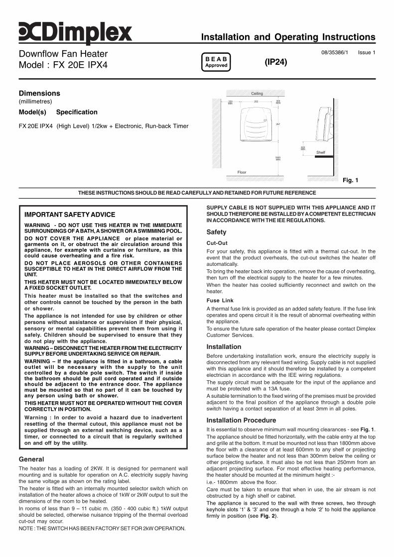
Fig. 1
(IP24)
IMPORTANT SAFETY ADVICE
WARNING - DO NOT USE THIS HEATER IN THE IMMEDIATESURROUNDINGS OF A BATH, A SHOWER OR A SWIMMING POOL.DO NOT COVER THE APPLIANCE or place material orgarments on it, or obstruct the air circulation around thisappliance, for example with curtains or furniture, as thiscould cause overheating and a fire risk.DO NOT PLACE AEROSOLS OR OTHER CONTAINERSSUSCEPTIBLE TO HEAT IN THE DIRECT AIRFLOW FROM THEUNIT.THIS HEATER MUST NOT BE LOCATED IMMEDIATELY BELOWA FIXED SOCKET OUTLET.
This heater must be installed so that the switches andother controls cannot be touched by the person in the bathor shower.The appliance is not intended for use by children or otherpersons without assistance or supervision if their physical,sensory or mental capabilities prevent them from using itsafely. Children should be supervised to ensure that theydo not play with the appliance.WARNING – DISCONNECT THE HEATER FROM THE ELECTRICITYSUPPLY BEFORE UNDERTAKING SERVICE OR REPAIR.WARNING – If the appliance is fitted in a bathroom, a cableoutlet will be necessary with the supply to the unitcontrolled by a double pole switch. The switch if insidethe bathroom should be pull cord operated and if outsideshould be adjacent to the entrance door. The appliancemust be mounted so that no part of it can be touched byany person using bath or shower.THIS HEATER MUST NOT BE OPERATED WITHOUT THE COVERCORRECTLY IN POSITION.
Warning : In order to avoid a hazard due to inadvertentresetting of the thermal cutout, this appliance must not besupplied through an external switching device, such as atimer, or connected to a circuit that is regularly switchedon and off by the utility.
GeneralThe heater has a loading of 2KW. It is designed for permanent wallmounting and is suitable for operation on A.C. electricity supply havingthe same voltage as shown on the rating label.The heater is fitted with an internally mounted selector switch which oninstallation of the heater allows a choice of 1kW or 2kW output to suit thedimensions of the room to be heated.In rooms of less than 9 – 11 cubic m. (350 - 400 cubic ft.) 1kW outputshould be selected, otherwise nuisance tripping of the thermal overloadcut-out may occur.NOTE : THE SWITCH HAS BEEN FACTORY SET FOR 2kW OPERATION.
08/35386/1 Issue 1
THESE INSTRUCTIONS SHOULD BE READ CAREFULLY AND RETAINED FOR FUTURE REFERENCE
SUPPLY CABLE IS NOT SUPPLIED WITH THIS APPLIANCE AND ITSHOULD THEREFORE BE INSTALLED BY A COMPETENT ELECTRICIANIN ACCORDANCE WITH THE IEE REGULATIONS.
Safety
Cut-Out
For your safety, this appliance is fitted with a thermal cut-out. In theevent that the product overheats, the cut-out switches the heater offautomatically.To bring the heater back into operation, remove the cause of overheating,then turn off the electrical supply to the heater for a few minutes.When the heater has cooled sufficiently reconnect and switch on theheater.
Fuse Link
A thermal fuse link is provided as an added safety feature. If the fuse linkoperates and opens circuit it is the result of abnormal overheating withinthe appliance.To ensure the future safe operation of the heater please contact DimplexCustomer Services.
InstallationBefore undertaking installation work, ensure the electricity supply isdisconnected from any relevant fixed wiring. Supply cable is not suppliedwith this appliance and it should therefore be installed by a competentelectrician in accordance with the IEE wiring regulations.The supply circuit must be adequate for the input of the appliance andmust be protected with a 13A fuse.A suitable termination to the fixed wiring of the premises must be providedadjacent to the final position of the appliance through a double poleswitch having a contact separation of at least 3mm in all poles.
Installation ProcedureIt is essential to observe minimum wall mounting clearances - see Fig. 1.The appliance should be fitted horizontally, with the cable entry at the topand grille at the bottom. It must be mounted not less than 1800mm abovethe floor with a clearance of at least 600mm to any shelf or projectingsurface below the heater and not less than 300mm below the ceiling orother projecting surface. It must also be not less than 250mm from anadjacent projecting surface. For most effective heating performance,the heater should be mounted at the minimum height :-i.e.- 1800mm above the floor.Care must be taken to ensure that when in use, the air stream is notobstructed by a high shelf or cabinet.The appliance is secured to the wall with three screws, two throughkeyhole slots ‘1’ & ‘3’ and one through a hole ‘2’ to hold the appliancefirmly in position (see Fig. 2).

Fig. 2
The product complies with the European Safety Standards EN60335-2-30 and the European Standard Electromagnetic Compatibility (EMC) EN55014, EN60555-
2 and EN60555-3. These cover the essential requirements of EEC Directives 2006/95/EC and 2004/108/EC
[c] Dimplex UK LimitedAll rights reserved. Material contained in this publication may not be reproduced in whole or in part, without prior permission in writing of Dimplex UK Limited.
Fig. 3 - FX20E IPX4 Wiring Diagram
Fig. 4
1. Remove the top cover from the appliance by removing the twoscrews securing the top cover and hinging it back.
2. Mark the position of the two keyhole slots ‘1’ & ‘3’ (see Fig. 2 fordimensions) on the wall and drill and plug for the two suitablescrews.
3. Partially insert the two screws, then hang the appliance on thesescrews. Mark the position of the third hole. this is used to secure theproduct.
4. Remove the appliance and drill and plug for the third screw.5. Remount the appliance on the wall using the two keyhole slots.6. Feed the supply cord or wires through the inlet at the top rear of the
appliance leaving sufficient free length to connect to the terminalblock.
7. Make electrical connections to the terminal block ensuring that thelive connection is made to the terminal marked ‘L’ and the neutralconnection to the terminal marked ‘N’ (see Fig. 2 exploded view).
8. Fix the product inplace by inserting and tightening the third screw.Fix mains cable securly using the products cable clamp
9. Set the selector switch to provide either 1kW or 2kW output.10. Replace the top cover and screws.
The appliance is now ready for use and the electricity supply can bereinstated.
ControlsThe cut-out is a safety device which switches off the heater and fan iffor any reason the appliance overheats - see ‘Safety’.The thermal fuse link is provided as an added safety feature, andoperates to open circuit if there is abnormal overheating within theappliance. The operation of these safety devices is described under‘Safety’.This model has a run-back timer which can be set on a run time of 5 –155 minutes. This can be adjustedby removing the top cover andmoving the jumpers on the timer,e.g. to run the timer for 65 mins.you leave the 5, 20 & 40 minjumpers in the closed position (i.e.the closed position is when thejumper covers the two pins ontimer), and move the remainingjumpers to open position or on onepin only, which provides nocontact between pins. (see Fig.4 for setting for 65 mins.).Note: The run-back perioddefaults to 15 minutes when all jumpers are in the open position.At the end of a timer run-back period, the appliance can be restarted bypulling the cord twice; the red neon light will extinguish after the first pull,and will light up again after the second pull.
Cleaning and User Maintenance
WARNING
BEFORE UNDERTAKING CLEANING OR MAINTENANCE WORK ON THEAPPLIANCE IMMEDIATELY DISCONNECT THE ELECTRICITY SUPPLY BYSWITCHING OFF AT THE ADJACENT DOUBLE POLE SWITCH.The outside can be cleaned by wiping it over with a soft damp cloth andthen dried. Do not use abrasive cleaning powders or furniture polish asthis can damage the surface finish.Ensure that dust or fluff does not accumulate inside the heater as thiscould lead to overheating of the element. Use a vacuum cleaner to removeany fluff which does accumulate.
RecyclingFor electrical products sold within the European Community.
At the end of the electrical products useful life it should notbe disposed of with household waste. Please recycle wherefacilities exist. Check with your Local Authority or retailer forrecycling advice in your country.
After Sales ServiceYour product is guaranteed for one year from the date of purchase.Within this period, we undertake to repair or exchange this product freeof charge subject to availability provided it has been installed and operatedin accordance with these instructions.Your rights under this guarantee are additional to your statutory rights,which in turn are not affected by this guarantee.Should you require after sales information or assistance with this productplease go to www.dimplex.co.uk where you will find our self helpguide by clicking on “After Sales” or ring our helpdesk on 0845 600 5111(UK) or 01 842 4833 (R.O.I.) .Spare parts are also available on the websitewww.dimplex.co.ukPlease retain your receipt as proof of purchase.
Dimplex UK Ltd.Millbrook HouseGrange DriveHedge EndSouthamptonHampshire. SO30 2DF
www.dimplex.co.uk
Republic of Ireland Tel. 01 8424833