douglas aircraft company md-83, g-devr: main document
TRANSCRIPT

Main landing gear collapse on landing, Douglas Aircraft Company MD-83,G-DEVR
Micro-summary: The main landing gear of this Douglas Aircraft Company MD-83collapsed during landing roll.
Event Date: 1995-04-27 at 2316 UTC
Investigative Body: Aircraft Accident Investigation Board (AAIB), United Kingdom
Investigative Body's Web Site: http://www.aaib.dft.gov/uk/
Note: Reprinted by kind permission of the AAIB.
Cautions:
1. Accident reports can be and sometimes are revised. Be sure to consult the investigative agency for thelatest version before basing anything significant on content (e.g., thesis, research, etc).
2. Readers are advised that each report is a glimpse of events at specific points in time. While broadthemes permeate the causal events leading up to crashes, and we can learn from those, the specificregulatory and technological environments can and do change. Your company's flight operationsmanual is the final authority as to the safe operation of your aircraft!
3. Reports may or may not represent reality. Many many non-scientific factors go into an investigation,including the magnitude of the event, the experience of the investigator, the political climate, relationshipwith the regulatory authority, technological and recovery capabilities, etc. It is recommended that thereader review all reports analytically. Even a "bad" report can be a very useful launching point for learning.
4. Contact us before reproducing or redistributing a report from this anthology. Individual countries havevery differing views on copyright! We can advise you on the steps to follow.
Aircraft Accident Reports on DVD, Copyright © 2006 by Flight Simulation Systems, LLCAll rights reserved.
www.fss.aero

Douglas Aircraft Company MD-83, G-DEVR: Main document
Aircraft Accident Report No: 1/97 (EW/C95/4/2)
Report on the accident to Douglas Aircraft Company MD-83, G-DEVR at Manchester Airport on 27 April 1995
Contents
• Synopsis • 1. Factual Information • 1.1 History of the flight • 1.2 Injuries to persons • 1.3 Damage to aircraft • 1.4 Other damage • 1.5 Personnel Information • 1.6 Aircraft information • 1.6.1 Leading particulars • 1.6.2 Development of the MD-80 Series of aircraft • 1.6.3 Description of the Landing Gear • 1.6.3.1 General • 1.6.3.2 Main Landing 'Gear Walking' • 1.6.3.3 Fatigue Life Calculations for the Main Landing Gear • 1.6.3.4 In-Service Inspections and Overhaul • 1.6.3.5 MD-83 Main Landing Gear fleet history • 1.6.4 Technical records • 1.6.5 Aircraft data • 1.7 Meteorological information • 1.8 Aids to navigation • 1.9 Communications • 1.10 Aerodrome information • 1.11 Flight recorders • 1.11.1 Cockpit voice recorder (CVR) • 1.11.2 Digital flight data recorder (DFDR) • 1.11.3 Analysis of the flight recorder information • 1.12 Examination of aircraft • 1.12.1 On-site examination • 1.12.2 Metallurgical examination • 1.13 Medical and pathological information • 1.14 Fire • 1.15 Survival aspects • 1.16 Tests and research • 1.16.1 Examination of the surface finish applied to Main Landing Gears • 1.16.2 Calculation of the stress levels experienced by the Main Landing Gear • 1.16.3 Flight Tests to verify stresses experienced by the Main Landing Gear • 1.16.4 In-service measurement of stresses in the Main Landing Gear of G-DEVR • 1.16.5 Tests on anti-skid and brake components • 1.16.6 Non-destructive Testing of other MD-83 Main Landing Gear in the Airtours fleet • 1.17 Organisational and management information • 1.18 Additional information

• 1.18.1 Sphere of operation and utilisation • 1.18.2 Landing technique • 1.18.3 Properties of 300M material • 1.18.4 Post-accident DAC/Regulatory Authority Actions • 1.18.5 History of MD-80 Main Landing Gear vibration • 1.19 Useful or effective investigation techniques • 2 Analysis • 2.1 Flight crew operating technique • 2.2 Origin of the Main Landing Gear failure • 2.3 Post Accident DAC/Regulatory AuthorityAction • 2.4 Reporting of persons on board • 2.5 Aircraft evacuation • 2.6 Forward passenger entrance door • 2.7 Arming/disarming of doors • 2.8 Passenger briefing • 2.9 Landing gear warning • 3 Conclusions • 3(a) Findings • 3(b) Causes • 4 Safety Recommendations
• Appendix A • Appendix B - Figure 1 • Appendix B - Figure 2 • Appendix C • Appendix D • Appendix E • Appendix F • Appendix G • Appendix H • Appendix I
Registered Owner and Operator: Airtours International Aviation (Guernsey) Ltd
Aircraft Type: Douglas Aircraft Company MD83
Nationality: British
Registration: G-DEVR
Place of accident: Manchester Airport
Latitude: 53°21'N
Longitude: 002°16'W
Date and Time: 27 April 1995 at 2316 hrs
All times in this report are UTC

Synopsis
The accident was notified to the Air Accidents Investigation Branch (AAIB) at 2345 hrs on 27 April 1995 by the Air Traffic Control (ATC) Watch Manager at Manchester Airport. The AAIB team comprised Mr D F King (Investigator in Charge), Mr P N Giles (Operations), Mr S W Moss (Engineering) and Mr R Vance (Flight Recorders).
The aircraft landed at Manchester at 2316 hrs and the commander took control from the first officer during the latter part of the landing roll. As he applied increased pressure to the brakes there was a loud bang and the left wing dropped as the left Main Landing Gear (MLG) collapsed. The aircraft came quickly to a halt and the commander decided to disembark the passengers via the front passenger entrance door and stairs. The cabin supervisor experienced a problem with the stairs and, after a discussion with the commander, the passengers were evacuated via the front and rear service doors using the escape slides. An orderly evacuation ensued with only minor injuries being sustained; all passengers had left the aircraft by 2326 hrs.
The investigation identified the following causal factors:-
(1) The left MLG outer cylinder failed on the application of bending loads resulting from normal braking due to the presence of a fatigue crack, 5 mm long by 1.25 mm deep, located on the front face of the cylinder, close to a change in section, where bending stresses were maximum.
(2) The fatigue origin was associated with surface features produced by the gritblasting used to prepare the steel surface for high current density cadmium plating.
(3) Loads not predicted during the MLG design were encountered early in the aircraft's life when 'gear walking', a MLG fore and aft vibration mode, was encountered. As a result fatigue initiated and propagated through the immediate compressive subsurface layer produced by shot peening and designed to improve fatigue resistance.
Two safety recommendations are made.
1 Factual Information
1.1 History of the flight
The aircraft was on a flight from Las Palmas Airport, Canary Islands to Manchester Airport. The flight was uneventful and the aircraft intercepted the localiser at 20 nm for an Instrument Landing System (ILS) approach to runway 06; the first officer was the handling pilot.
The aircraft landed at 2316 hrs; the touchdown was normal and both main wheels made contact at about the same time. The spoilers deployed automatically and reverse idle was selected. The left Engine Pressure Ratio (EPR) was slightly higher than the right, however, the first officer retarded the left throttle to match the engines. As the aircraft slowed the commander made calls at 80 kt and 60 kt. Shortly after this latter call he told the first officer that he was joining him on the brakes. As he applied increased pressure to the brakes there was a loud bang and the left MLG collapsed.
The aircraft came quickly to a halt and the commander instructed the first officer to make a PAN call. He then, using the public address (PA) system, told the cabin attendants and passengers to

remain seated. Both engines were shutdown but the Auxiliary Power Unit (APU) was left running to maintain an electrical supply.
At 2317 hrs, on receipt of the PAN call, the aerodrome controller pressed the crash alarm. The Airport Fire Service (AFS) responded immediately and were at the site, adjacent to link 'C', about one minute later; the Assistant Divisional Officer ordered the immediate deployment of foam hand lines at the front and rear of the aircraft to cover a small fuel spillage from the outboard section of the left wing. ATC requested the number of Persons On Board (POB) and the first officer replied, "169 PLUS 2".
Rather than order an emergency evacuation the commander took stock of the situation and assessed that there was no immediate danger. Further, he considered that there was less likelihood of injury to the passengers if they were disembarked in a unhurried manner. The cabin supervisor went onto the flight deck and it was decided to disarm all doors but to disembark the passengers through the forward passenger entrance door and stair only. The commander then briefed the passengers on his intentions.
The cabin supervisor told the other cabin attendants to prepare their doors for arrival. She disarmed the forward passenger entrance door, checked the immediate area through the viewing window and opened the door; it took three attempts to engage the door gust lock. The stair did not appear to extend correctly and so she decided to retract it, close the door and re-arm the slide, however, she was unable to release the gust lock to close the door. She then told the commander about the problem and the decision was made to use the forward and rear service doors; these doors were then re-armed and the slides were deployed. The commander briefed the passengers on the change of plan and the evacuation commenced at about 2320 hrs.
The landing gear aural warning had been sounding since the landing gear collapse and the flight crew decided to take action to remove this particular distraction before they considered their next actions. The circuit breaker was located and pulled; the warning silenced at 2323 hrs.
The majority of the passengers moved towards the forward door, however, the cabin staff redirected some of those in the centre section towards the rear and an orderly evacuation ensued through the two service doors with only minor injuries being sustained. AFS personnel assisted the passengers from the aircraft and escorted them to coaches, which were waiting at link 'C' north. The evacuation of the passengers was complete by 2326 hrs.
Having checked the cabin, the supervisor informed the commander that all the passengers were off and the cabin attendants then vacated the aircraft. The flight deck crew left when they had completed the shut down drills at about 2330 hrs. The Assistant Divisional Officer then went on board and confirmed that the aircraft was empty.
1.2 Injuries to persons
Injuries Crew Passengers Others
Fatal - - -
Serious - - -
Minor/none 7 171 -

1.3 Damage to aircraft
See § 1.12 Examination of the Aircraft.
1.4 Other damage
Contamination of and minor damage to runway surface.
1.5 Personnel information
1.5.1 Commander: Male, aged 33 years
Licence: Airline Transport Pilot's Licence
Aircraft ratings: MD83
Instrument rating: 21 November 1994
Base check: 25 April 1995
Line check: 8 December 1994
Medical certificate: Class 1 issued 23 February 1995
Limitations: None
Flying experience: Total all types: 5,900 hours
Total on type: 2,100 hours
Total last 28 days: 45 hours
Total last 24 hours: 6 hours
Previous rest period: Off duty: 1430 hrs on 26 April 1995
On duty: 1400 hrs on 27 April 1995
1.5.2 First officer: Male, aged 32 years
Licence: Airline Transport Pilot's Licence
Aircraft ratings: MD83
Instrument rating: 3 February 1995
Base check: 3 February 1995
Line check: 21 September 1994

Medical certificate: Class 1 issued 1 December 1994
Limitations: None
Flying experience: Total all types: 4,570 hours
Total on type: 1,300 hours
Total last 28 days: 81 hours
Total last 24 hours: 6 hours
Previous rest period: Off duty: 2100 hrs on 26 April 1995
On duty: 1400 hrs on 27 April 1995
1.6 Aircraft information
1.6.1 Leading Particulars
The MD-80 series of aircraft are cantilever low wing monoplane, short/medium range airliners with two Pratt and Whitney JT8D engines pod mounted, one either side of the rear fuselage. The MD-83 has a wing span of 32.87 m and an overall length of 45.06 m. The manufacturer's serial number for G DEVR was 49941 and it was delivered in 1990. At the time of the accident it had accumulated a total of 18,236 flying hours and 6,386 landings.
1.6.2 Development of the MD-80 series of aircraft
The MD-80 series of aircraft are direct descendents of the Douglas DC-9 family and share many common components. In general, however, they have higher capacity and operating weights compared with the DC-9 and in particular this necessitated a stronger landing gear. In order to maintain commonality and to utilise the existing forging dies, the increased strength required from the MLG oleo leg was achieved by a change of material for the piston and cylinder. The original 'HyTuf' to specification AMS 6418 was replaced by ultra-high tensile 300M steel to Douglas Material Specification (DMS) 1935/MILS8844.
1.6.3 Description of the Landing Gear
1.6.3.1 General
The MD-80 MLG is of conventional configuration, retracting inwards (Appendix A). Suspension and damping are achieved by an oleo pneumatic piston operating in a cylinder, with torsional motion being prevented by a torque link incorporating a shimmy-damper. The cylinder, including the trunnions, is a single forging of 300M ultra high tensile steel, as is the piston which incorporates the axle.
The MD-80 MLGs were designed by the Douglas Aircraft Company (DAC) but subcontracted out for manufacture. They were originally produced by Cleveland Pneumatic (now B F Goodrich) but in 1989 production switched to Menasco Aerospace of Ontario, Canada. Both manufacturers worked

to the same drawings and the landing gears are interchangeable both as a complete unit and at the individual component level.
The component which failed on G-DEVR was the left-hand cylinder (§ 1.12). After forging, the cylinders are heat-treated and machined to the drawing dimensions. They are then shot-peened to Douglas Process Specification DPS 4.999, following which they are blasted with aluminium oxide grit to prepare the surface for cadmium plating. After plating is completed the surface is primed and painted with an impact-resistant paint. The foregoing description is only a brief summary of the most significant of the many processes involved in the manufacture of the cylinder, a highly-loaded precision component.
In order to comply with International Airworthiness Regulations relating to crashworthiness, the MLG design incorporates 'fuse pins', associated with the attachment of the cylinder to the wing structure, which are designed to fail if excessive loads are experienced during take off or landing. The intention was that these pins would cause the landing gear to detach cleanly, without rupturing the fuel tanks, assuming that the overload was to occur in an aft-and-upward direction. However, there was a position identified on the cylinder itself which could also fail under abnormal loading, since the bending moment during braking and wheel spin-up were highest at this point and the thickness of the material resulted in a stress reserve factor close to unity (§ 1.16.2). This 'critical' cross section occurred immediately below a reduction in cylinder wall thickness approximately 18 inches below the centreline of the landing gear mounting trunnion. Although this was effectively a 'weak point' on the leg, it was considered by DAC that it met the normal stress requirements, albeit marginally, and that its position close to the top of the leg gave an additional safeguard against wing tank rupture in the runway overrun case.
The braking system is of the traditional type with an electronic antiskid system controlling conventional hydraulic brakes with discs of steel construction. Signals from each main wheel speed sensor are input to the Antiskid Control Unit which outputs a signal to the associated Anti-skid Control Valve, causing a removal of hydraulic pressure to the relevant brake unit if an impending skid is sensed. As the wheel accelerates again the pressure is re-applied at a lower value until a further impending skid is sensed, when it is again released. This is repeated until,assuming a constant pilot's pedal pressure and a constant runway friction coefficient, the brake pressure settles down at a value just optimised for maximum braking effort without causing a skid.
1.6.3.2 Main Landing 'Gear Walking'
'Gear walking' (§ 1.18.5) is a term used to describe a mode of MLG self sustaining vibration. It is primarily due to a dynamic coupling of the characteristics of the anti-skid system with the natural fore-and-aft frequency of the MLG leg and can be additionally affected by such factors as tyre pressures and the bleed condition of the brake system hydraulics. On the application of sufficient brake pressure the MLG legs flex rearwards and when an incipient skid is detected by the antiskid system the brake pressure is released. On brake release the leg 'springs' forward, rapidly accelerating the wheel which signals the anti-skid system to re-apply the brakes. On brake re-application the leg again flexes rearwards and so on.
1.6.3.3 Fatigue life calculations for the Main Landing Gear

During development of the DC-9 aircraft, strain gauge and full-scale fatigue tests were carried out on the landing gears. With the advent of the MD-80 no such testing was done and verification of the loading and fatigue life of the MLG was achieved by calculation and extrapolation of the data from the DC-9 tests. Fatigue and fracture toughness information for 300M material was taken from the material specification and from DAC's own testing data (§ 1.18.3). The test regime employed used un-peened material, as it was felt that any benefit peening might bring to the fatigue life should be considered a 'bonus' to the fatigue life calculations.
The fatigue calculations involved devising a spectrum of 'typical' mission profiles with taxy, take off and landing loads calculated for various assumed aircraft weights and variation of pilot technique (heavy/moderate braking, normal/firm/heavy landings etc). An assumed number of occurrences for each mission profile was included in the total spectrum for the aircraft's life together with various known transient or oscillatory loading modes. Principal stresses calculated for each case were factored using a figure of stress concentration (K1) to take into account changes in material cross section occurring at the various critical points being considered.
For the landing and braked roll case for the cylinder, the calculations centred on the 'critical' section mentioned in § 1.6.3.1 above in recognition that the stresses would be highest at this point. The data showed that, in terms of fore-and aft stresses on the cylinder, only 3 produced stress values sufficient to cause fatigue damage. These were particular wheel spin-up (SU) and springback loads and a fore-and-aft transient drag oscillation (TDO) occurring on touchdown. Although one of the SU stresses was high, in the order of 220 ksi (thousands of pounds per square inch), this was for a heavy landing case of which only some 12 events were forecast in the typical life of the landing gear. Thus in terms of fatigue propagation it amounted to a small amount of damage because the number of stress cycles was so low. In the other two spring-back and TDO cases the stresses were much lower (in the order of 150 ksi) but there were a larger number of cycles for a given number of flights.
Based on a maximum expected component life of 150,000 flights the above calculations gave a safe life limit of 12 million cycles - effectively unlimited.
1.6.3.4 In-Service inspections and overhaul
As a safe life component, the cylinder was not subjected to any in-service Non Destructive Inspections (NDI) beyond routine visual checks for impact damage to the paint surface. The following inspection was required to be completed at each 'A Check' scheduled every 120 flying hours:-
2 Inspect main landing gear component assemblies and installations
A Check the landing gear shock struts, torque arms, linkage, proximity sensor, anti-skid, wiring and hydraulic fittings and lines for general condition, attachment, leakage, corrosion and visual damage.
Note: Nicks and dings up to 0.005 inch in depth should be repainted. Damage 0.005 to 0.030 inch must be blended, smoothed and painted. Damage deeper than 0.030 should have Engineering Department Disposition.
At overhaul the cylinder would receive a magnetic particle crack check with the paint and Cadmium plating removed. The purpose of the overhaul was primarily aimed at inspection/replacement/repair of the moving parts of the landing gear assembly and the periodicity was not based on any requirement to perform NDI on the cylinder. Approved operator
overhaul lives varied widely across the MD-80 fleet but for Airtours, with a relatively high flying hours/landings ratio, the approved life was 9 years, which equated to about 12,000 landings. The landing gears on G-DEVR were those fitted during production and were thus slightly more than halfway through their approved overhaul life.
1.6.3.5 MD-83 Main Landing Gear fleet history
Information from the manufacturer suggests that there were no recorded cases of fatigue cracks in the 'critical' region of the cylinder either in-service or at overhaul and certainly no cases of complete failure as occurred on G-DEVR. Douglas Aircraft were not in possession of accurate data on high-time MD-80 landing gear cylinders, due to the different overhaul cycle and the fact that landing gear components are often interchanged at this stage. However, an informal survey suggested that MLG cylinders existed with in excess of 35,000 landings accumulated, approximately 5.5 times as many as accumulated by G-DEVR's landing gear at the time of the accident.
1.6.4 Technical records
The aircraft possessed a Certificate of Airworthiness expiring on 27 February 1996 and a Certificate of Maintenance Review valid until 20 July 1995.
In August 1992, this aircraft (then registered GJSMC) was involved in an incident whereby the left wing tip made light contact with the runway whilst landing at Gatwick airport. This incident was the subject of an AAIB field investigation and is reported in AAIB Bulletin 12/92. No malfunction of the aircraft was suspected and the damage to the left wing was minor. Although the aircraft had touched-down on the left MLG first, it was not categorised as a 'heavy landing'. All parties to this investigation are of the opinion that this earlier incident was not relevant to the subsequent failure of the left MLG.
A review of the aircraft's technical records did not reveal any unscheduled maintenance on the left MLG cylinder although a few crew reports had been received concerning the left MLG. None of these were considered to be relevant to this accident with the possible exception of a report in the technical log dated 21/06/91:-
Brake press showed 3,200-3,300 psi during taxy out and during first light application - a savage snatch /judder resulted from main gear followed by pressure dropping to the normal range 2,500-3,000 psi.
The rectification action column for this defect recorded that the brake pressures and cylinders were checked and pronounced normal. No further reports of this nature were recorded.
1.6.5 Aircraft data
Take off weight (TOW) 154,905 lb
Maximum TOW 160,000 lb
Zero fuel weight (ZFW) 116,900 lb
Maximum ZFW 122,000 lb

Fuel on landing 9,400 lb
Landing weight (LW) 126,300 lb
Maximum LW 139,500 lb
VREF - 40° flap 130 kt
1.7 Meteorological information
The meteorological observation made at 2317 hrs recorded the surface wind as 080°/6 kt and the temperature was 6° C.There were no other relevant meteorological factors.
1.8 Aids to navigation
Not relevant
1.9 Communications
From 2314 hrs the aircraft was in contact with Manchester Aerodrome Control on frequency 118.62 MHz. This frequency was recorded and a transcript was made. There were no communications problems.
The controller advised the crew to listen out on 121.6 MHz if they wished to talk to the AFS. No communication was made on this frequency.
1.10 Aerodrome information
The aircraft landed on runway 06; the landing distance available was 8,599 ft and the runway was dry. All runway lighting was serviceable. There were no other relevant factors
1.11 Flight Recorders
The aircraft was fitted with a 30 minute duration Cockpit Voice Recorder (CVR) and a 25 hour duration Digital Flight Data Recorder (DFDR). Both recorders were undamaged in the accident; they were removed from the aircraft and taken to the AAIB's flight recorder replay and analysis facilities at Farnborough.
1.11.1 Cockpit voice recorder (CVR)
The CVR was fully serviceable. The four channel installation was configured to the 'hot mic' standard (Flight crew boom microphones active at all times) with a cockpit area microphone (CAM) channel, individual channels for each pilot's microphone and a channel for the public address, (PA). The recording contained information on the approach to and the landing at Manchester, and on the evacuation of personnel from the aircraft after the accident. The approach to Manchester was uneventful. From the CAM channel recording it was evident that the aircraft made a gentle touchdown, this was followed with comment on a "split" between the left and right engine thrust

reverse indications. A short time after calling 60 kt the commander said, "joining you on the brakes": this comment was followed almost immediately by a loud bang and then the sounds of tearing metal. The landing gear unsafe horn sounded followed by a synthesised female voice saying, "landing gear". The horn and voice repeated every 1.5 seconds for the following 6 minutes. The CAM and PA channels recorded the instructions for the evacuation of the aircraft. The CVR continued to record until the electrical power was switched off, some 5 minutes after the passengers had vacated the aircraft.
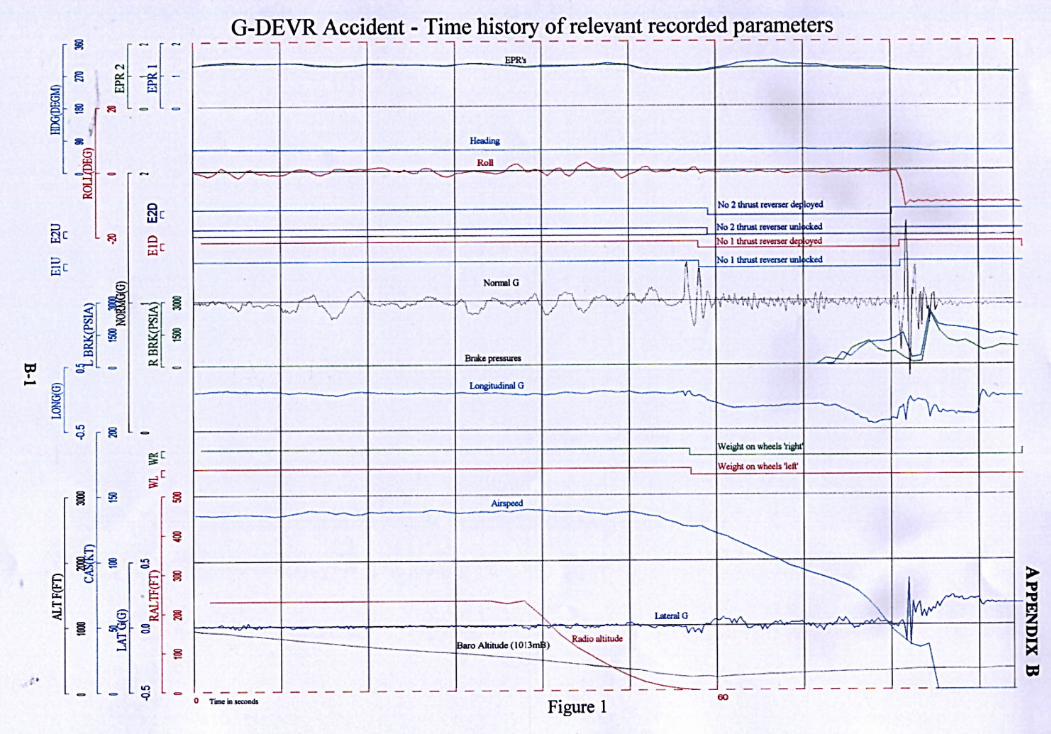
1.11.2 Digital flight data recorder (DFDR)
The DFDR recorder contained a record of the time histories of 81 parameters. Of particular importance to the investigation were the recorded time histories of longitudinal acceleration, reverse thrust, brake pressures and the weight on wheels sensors. Figure 1 at Appendix B is a graphical representation of the time history of these and other relevant parameters, reduced to engineering values, during the accident landing.
From figure 2 Appendix B it can be seen that after a stabilised approach to runway 06 the aircraft touched down at 126 kt, initially on the right MLG. Reverse thrust was selected, the thrust recorded corresponded to reverse idle power being used and confirms the comments on the CVR of the split between the left and right engines. From the time history of longitudinal acceleration and the brake pressures it is clear that reverse thrust and aerodynamic braking only were used until the aircraft speed was below 87 kt. Wheel braking was then used and a maximum deceleration of 0.418 g was recorded at 62 kt. At 40 kt the aircraft began to tilt left wing down reaching a tilt angle of 11° to the left. The large amplitude excursions on the normal and lateral acceleration time histories occurred when the landing gear collapsed and the aircraft structure made contact with the runway. The aircraft then veered slightly to the right and stopped within 15 seconds. Electrical power to the DFDR was removed as soon as the engines stopped which was at the time the aircraft came to rest.
1.11.3 Analysis of the flight recorder information
In addition to providing DFDR data on the accident landing to the aircraft manufacturer and to specialist consultants the AAIB examined data from the three preceding landings recorded on the DFDR to discover if there was any earlier event that might have contributed to the landing gear collapse. None could be found.
The aircraft manufacture supplied DFDR data from a test flight landing where a phenomenon described as 'gear walking' (§ 1.18.5) was confirmed. Using this as a reference in excess of 50 landings of MD-80 series aircraft were examined in an effort to identify any occurrence of the phenomenon. No further evidence of 'gear walking' was found.
A copy of a CVR tape from a test flight where 'gear walking' was induced was provided to assist in the analysis of the CVR from the accident flight. No characteristics of the audio signatures on the accident recording corresponded with the 'gear walking' sounds on the test flight tape.
1.12 Examination of the aircraft
1.12.1 On-site examination

When the AAIB team examined the aircraft, it was being towed into a maintenance hangar with the left wing supported by an air bag on a flat-bed lorry. The broken left MLG had been roped in approximately the position it had adopted on the runway with the tyres resting against the badly distorted and torn inboard flap (photograph Appendix C). The lower half of the broken leg was still attached to the aircraft by the sidestay, which had suffered gross distortion. The tyres were still inflated and the torque link and shimmy damper were undamaged. The overall impression was that the leg had rotated directly aft after failure, indeed in the manner in which it was intended had the failure occurred due to a heavy landing or runway overrun.
Damage to the airframe was very much as might be expected from this sort of event. The aircraft had come to rest on the left wing tip, outboard flaps and slats, all of which had severe scraping damage. Several flap hinges were scraped and distorted. The primary wing structure, including the integral fuel tank, was intact and had not been penetrated, although there was some scraping of the lower skin in the region of the front spar. On-site reports of fuel leakage are considered to have been due to drainage from the outboard surge tanks as a result of the left-wing-low attitude. All the damage was subsequently repaired by a DAC repair team but new flap and slat sections were required to be fitted.
The MLG leg itself had fractured at the top of the cylinder in the manner shown in Appendix A. First examination suggested that the fracture face possessed only the characteristics of brittle overload fracture with 'chevrons' pointed towards a failure origin at the front of the cylinder. Closer examination of this origin showed the presence of a very small, brown-coloured and crescent-shaped area (Appendix D). As this bore the characteristics of a pre-existing defect, the AAIB requested the presence of a metallurgist to confirm the nature of the anomaly.
The metallurgist rapidly identified that the defect exhibited the characteristics of fatigue, and it was considered that, even though this defect was extremely small, it was probably responsible for failure of the leg, bearing in mind the characteristics of the 300M, high-strength steel used in its construction (see §1.18.3). This information was immediately transmitted to the United States National Transportation Safety Board, Douglas Aircraft Company and the UK Civil Aviation Authority. A team of three specialists from DAC were despatched to examine the component on-site and they agreed with this initial appraisal.
The broken halves of the cylinder were removed and despatched to the DRA at Farnborough for detailed investigation. The remaining left MLG components were impounded at Manchester pending possible further testing but the rest of the aircraft was released for survey and repair work to commence.
1.12.2 Metallurgical examination
The failure was examined both optically and using a Scanning Electron Microscope (SEM). In addition to the obvious area of fatigue damage noted above, two further small areas adjacent to the main area could also be seen. The remainder was fast fracture (Appendix E). These pre-existing cracks had occurred in the run-out of a blend radius. The major fatigue crack was measured as 5 mm long by 1.25 mm deep.
Under high magnification on the SEM it could be seen that the fatigue was multi-origined and appeared to be associated with discontinuities observed on the surface of the specimen (Appendix F). The nature of these discontinuities was initially not understood. As noted in § 1.6.3.1, the surface of the cylinder was shot-peened after machining although it was not appreciated at first

that the next process involved grit-blasting prior to plating with cadmium. It was also not initially appreciated that the high current density used in the plating process (to minimise hydrogen entrapment) resulted in the 'lumpy', uneven appearance of the cadmium which was also noted.
Further examination revealed the presence of some small particles of aluminium oxide grit trapped in the surface folds beneath the cadmium plating and also the presence of microscopic fatigue cracks apparently growing from some of the sharpest and deepest folds (Appendix F). A more detailed appraisal of this aspect of the surface finish appears in the § 1.16.1. There were no signs of any other material defects such as corrosion pitting or material inclusions which could have acted as an origin for the development of fatigue cracking.
One half of the specimen from the lower portion of the fracture was supplied to DAC for independent analysis. They were essentially in agreement with the DRA findings and, like DRA, found that it was not possible to perform a striation count which might have revealed the number of stress cycles over which the fatigue crack had developed.
A further specimen was subjected to testing to determine the material properties against specification. The specimen complied with the specification; the results, together with discussion of the general characteristics of 300M steel are contained in § 1.18.3.
Finally, the cylinder was subjected to a check of its relevant dimensions, particularly its diameter, wall thickness and fillet radii. Bearing in mind the distortion suffered during the failure, it appeared that it conformed to the drawing requirements.
1.13 Medical and pathological information
There were no relevant medical factors
1.14 Fire
There was no fire
1.15 Survival aspects
There were no relevant survival aspects.
1.16 Tests and research
1.16.1 Examination of the surface finish applied to Main Landing Gears
The purpose of the shot-peening process is to cold work the surface of the metal to induce a layer of residual compressive stress. The depth over which this layer extends varies with the intensity of the peening and the coverage (number of times the material is subjected to shot impact). Menasco data suggests that,using their specification for 300M material, the compressive layer should extend for between 150 to 380 microns below the surface.

The presence of the compressive layer is intended to increase fatigue life by delaying the initiation/propagation of fatigue cracks which might otherwise develop from surface features; the tensile stresses due to leg bending being highest at the outer surface. Essentially, applied tensile stresses are offset by the residual compressive stress from peening.
The peening process itself involves impinging steel shot at high speed onto the surface using either compressed air or a rotating wheel. Wheel speed or air pressure and shot size are used to control the intensity of peening. With any material, shot with a hardness value at least equal to or preferably higher than the component is used to prevent breakage and distortion of the shot which can lead to tearing of the surface and 'skidding'. With 300M, very hard shot is required and high intensity if the peening is to be successful. The normal check for successful peening is a visual inspection of the surface using low-power magnification, whence small indentations (appearing as minute craters) can be discerned in an even pattern across the surface.
The process of abrasive blasting is intended to clean and prepare the surface for plating. Unfortunately, to some extent it also has the same effect as peening at low intensity but with 100% broken shot. The surface may be further cold-worked slightly but the alumina grit tears-up and smears the peened surface, obliterating the shot craters. It was this effect which was observed during the metallurgical examination described above and from which the fatigue had initiated. Menasco stated that only by abrasive blasting at 50 psi air pressure and above and using the specified medium (Nos 80120 alumina grit) would the correct surface be prepared for the high current density method of Cadmium plating necessary to release the hydrogen generated during the plating process. Indeed they pointed-out that, not only did the DAC specification call for this but seemingly every airframe and landing gear manufacturer to their knowledge specified similar or even more severe treatments on high-strength steels. It was also asserted that the kind of surface finish achieved on the specimen from G-DEVR was typical regardless of the which manufacturer did the work.
To test this last statement, the AAIB procured a specimen cut from an MD83 MLG cylinder produced by Cleveland Pneumatic and this was sectioned and examined under the SEM. The surface appeared similar to the G-DEVR specimen but the folds and discontinuities were to a somewhat lesser degree. Significantly, small embryonic fatigue cracks could be seen growing from some of the deeper folds again similar to the G-DEVR specimen.
Perhaps the most meaningful test for effectiveness of shot-peening is to measure the consequential residual stresses in the surface and sub-surface material. This is not an easy check since, although non-destructive electronic instruments are known to be available which claim to be able to test for residual stresses, other, more accurate methods are strictly destructive on the specimen. Samples from G-DEVR, close to the fracture, were subjected to such a process which involved progressively electro-polishing the surface away whilst subjecting it to XRay diffraction examination at each stage. These tests were done both at DRA and independently in the United States.
A graph of the results of the DRA tests is given at Appendix G. It can be seen that a residual compressive stress of about 720 MPa at the surface increases rapidly to a mean value of about 900 MPa until roughly 90 microns depth when the stress falls off rapidly, reaching a slight tensile value after 170 microns. The independent exercise conducted in the United States accorded extremely well with these results.
1.16.2 Calculation of the stress levels experienced by the Main Landing Gear

To better understand the stress levels experienced by the cylinder and to check the airworthiness certification information provided by DAC, the AAIB commissioned an initial mathematical study from a firm of consultants using basic aircraft data supplied by DAC. Based on this, a decision was to be taken as to whether more work would be necessary, particularly in the area of dynamic and transient responses. The consultants were also asked to look at the data from the flight recorder to see whether the accident landing sequence of events could be predicted by the mathematical model using the known extent of fatigue damage.
Their report confirmed the critical nature of the section of the cylinder where the failure occurred and thus concentrates on this area. The analysis used 'book' (ie Federal Airworthiness Requirements) values such as would be used in initial design of the MLG to ensure it would meet certification requirements and these were checked. It found that, for the design landing case, all parts of the cylinder met the requirements with a reserve factor (ratio of allowable stress to the calculated principal stress) greater than 1.10.
However, for the design braked roll case, the critical section gave a reserve factor of 1.0 and the report noted the extreme sensitivity of the resulting stresses to such factors as oleo extension and negative pitch attitude, an increase in either of which would cause the reserve factor to become less than unity and hence the landing gear would not meet certification requirements at the critical section. It was later discovered that the DAC analysis differed from the AAIB consultant's analysis inasmuch as the latter had used the FAR/JAR value of 0.8 as the braking coefficient of friction whilst the former had used the figure of 0.74. By adopting the lower figure, both parties agreed that the critical section would have a positive reserve factor. Discussion on the validity of using this figure is included in part 2 of this report.
The analysis also looked at the fatigue aspects of the design ,admittedly in a simplified form using several assumptions. The most significant assumption was that a stress concentration factor (K) in the range 1.5 to 2.0 was assumed. This factor is applied to the calculated principal stress to take into account the stress concentration which occurs due to the change in cross section of the material at the critical point. Such a factor can only be accurately calculated by using a detailed finite element analysis of the area and this fell outside the scope of the work requested by the AAIB.
Using a K of the above values and a simplified 'typical mission profile', the report concluded that a damage factor of about 0.15 would occur in 6,000 landings. Damage factor is defined as the ratio of the number of times fatigue damaging stresses are experienced (n) divided by the number of cycles to failure at that stress level (N). Thus this n/N value would predict failure after 40,000 landings, but the report noted that higher or lower values of K have a very large effect on the calculated fatigue life. It also acknowledged that the limited notched fatigue data available for 300M material further contributed to possible inaccuracy in the calculated fatigue life. Again, the DAC reaction to this conclusion is discussed in part 2 of this report.
A third aspect of the report examined the accident landing stresses using DFDR data to define the landing parameters and hence the loads experienced by the leg. This analysis confirmed that, during the accident landing, the actual loads experienced during the touchdown were very small and did not contribute to the subsequent failure of the cylinder. The application of the brakes (falling within the DAC definition of 'heavy' braking) during the landing roll however, applied much higher loads with the principal stresses approaching about two-thirds of the yield stresses for the material. When this value is applied to a cylinder containing a defect of the size subsequently known to have existed, brittle fast fracture is predicted if a stress concentration factor is included in the calculation. Brittle fast fracture is a term applied to an unexpected failure of a material like
300M, where large plastic strains would normally be noted before actual separation of the component under overload conditions, but due to the presence of a defect, brittle fracture without these characteristic plastic strain features occurs.
1.16.3 Flight Tests to verify stresses experienced by the Main Landing Gear
In July 1995, DAC decided to conduct a series of instrumented flight tests using their own MD87 aircraft, fuselage number 1326. Strain-gauges and accelerometers were fitted to a MLG and the aircraft was subjected to a range of landing and braking cycles at representative aircraft weights. In addition, the aircraft was fitted with a variety of brake/anti-skid systems from the two major vendors, including those fitted to G-DEVR at the time of the accident.
A further variation applied for the purposes of the tests was to introduce various sizes of restrictor in the hydraulic brake lines. This was to measure the stresses induced in the cylinder by a phenomenon known as 'gear walking' (§ 1.18.5). The purpose of the flight tests was to verify the calculated principal stresses both under normal operation and under conditions of 'gear walking'. At the same time, the effectiveness of the restrictors in suppressing 'gear walking' was tested.
It was found that, under rapid and heavy brake application at 40 kt (the known 'critical' condition at which walking can occur), if walking was not induced then the principal stresses were within the expected range. Oscillating maximum stresses in the order of 220 and 180 ksi were recorded with minimum stresses of 100 and 150 ksi respectively when 'gear walk' modes 1.1 and 1.2 were induced (§ 1.18.5). However, when 'gear walk' mode 2 was generated, the stresses became much higher, reaching levels of 272 ksi coupled with an additional fatigue-damaging minimum stress of 75 ksi. A chart of the measured stresses during 'gear walk mode 2' is given at Appendix H. From this it can be seen that the phenomenon appears to last for roughly seven or eight high-stress cycles, although the test aircraft was fitted with a 'fuse' which activated at a pre-set longitudinal acceleration value to prevent the oscillation becoming divergent and breaking the MLG leg. In-service aircraft are not fitted with such a device but the manufacturer considered that any occurrence of 'gear walk mode 2' would be so violent that the handling pilot would instinctively release the brakes.
The tests showed that the restrictors were successful in suppressing any tendency to excite 'gear walk' mode 2
1.16.4 In-service measurement of stresses in the Main Landing Gear of G-DEVR
In order to verify that the operator's environment for the MD83 was not generating in-service MLG stresses outside those assumed during the fatigue life calculations, DAC took the decision to instrument the replacement left MLG leg fitted to G-DEVR when it returned to service. By this time, G-DEVR and all other aircraft in the Airtours fleet had been fitted with restrictors to SB 32246 (§ 1.18.5) and 'gear walking' was not expected to occur. Indeed, on its first post-repair flight, G-DEVR was handled by a DAC test pilot who was unable to generate 'gear walking', despite several attempts using the known conditions under which it can occur.
The data gathered between 27 July 1995 and 10 February 1996 is presented in Appendix I. It shows that the stresses on the MLG were within the expected values apart from two excursions into the 160-180 ksi range
1.16.5 Tests on Anti-skid and Brake Components
The brake and anti-skid components were removed for examination. The antiskid control unit (part number 426071) and valves (part number 392492) were despatched to their manufacturer for functional testing. The control unit failed a section of the BITE (Built-in Test Equipment) test dealing with the parking brake monitoring circuit but was otherwise serviceable. This defect was not relevant to the circumstances of this accident.
Both the anti-skid valves were basically functional but it was noted that the valve gain (brake pressure versus current) plots were slightly out of limits. The manufacturer stated that the effect on anti-skid operation would not be compromised, since the control unit would simply produce the correct current to prevent skidding. DAC agreed with this but had, even before the accident to G-DEVR, also initiated a study of anti-skid control characteristics, including measurement of valve gain (not normally a measured parameter) in connection with their investigation of the 'gear walking' phenomenon. The accident valves were found to be at the highest extremes of the scatter of gain measured from many similar units.
DAC admit that they are unsure of the practical effect of this information but it appears they will not be pursuing this aspect any further since the installation of restrictors in the brake hydraulic circuits is successful in suppressing any tendency towards the MLG leg/anti-skid coupling effect which can result in walking.
1.16.6 Non-Destructive Testing of other MD-83 Main Landing Gears in the Airtours fleet
Prior to the issuance of DAC Alert Service Bulletin (ASB)MD8032A286 (§ 1.18.4) the maintenance organisation responsible for G-DEVR took a unilateral decision to perform a magnetic particle crack inspection in the critical area on all the MLG cylinders in the Airtours MD-83 fleet. Broadly similar-to the technique subsequently called-up in the ASB but without-the additional fluorescent dye-penetrant inspection, these checks did not find any indications of cracks.
1.17 Organisational and management information
There was no relevant organisational and management information
1.18 Additional information
1.18.1 Sphere of operation and utilisation
The company operated in the inclusive tour market on sector lengths of typically 3 to 4 hours flying time. The load factors were generally high and average take off and landing weights were of the order of 146,500 lb and 126,250 lb respectively. Peak aircraft utilisation was during the summer months and the fleet of eight aircraft had completed in the order of 6,000 cycles each.
The majority of MD83 aircraft are operated in the United States of America on scheduled passenger flights. The sector lengths are much shorter, averaging 40 minutes, but the take off and landing weights are generally lower. Aircraft of similar age to those operated by G-DEVR's operator would have accumulated about 11,000 cycles.
1.18.2 Landing technique

It was company policy that, under normal circumstances, maximum-reverse thrust should be used once the nosewheel had made contact with the runway unless noise restrictions dictated otherwise when reverse idle only would be used; maximum reverse thrust would be maintained until the aircraft speed had reduced to 80 kt. No record of the use of maximum reverse thrust existed, however, the company estimated that it was used on about 95% of daytime landings and 40% of night landings.
Unless safety dictated otherwise, no braking should be used above 80 kt. Below that speed progressive braking should be used; pilot's are discouraged from using excessively heavy braking to make an early turn off the runway.
1.18.3 Properties of 300M material
300M is a vanadium and silicon modified 4340 steel produced by vacuum melting. As used by DAC, to specification DMS 1935 or MILS 8844, the material has an Ultimate Tensile Strength (UTS) of 280 to 300 ksi and a 0.2% offset yield strength of 227 ksi (minimum). It has a Rockwell 'C' hardness in the range 53 to 55 and the fracture toughness K1c should be approximately 60 ksi√in.
The material properties of the fractured leg were measured by DRA Advanced Materials Division. The UTS, derived from a measured hardness of 53 Rockwell 'C' was 1,990 MPa (289 ksi) and the measured fracture toughness was 68.2 MPa√m (63.01 ksi√in)
1.18.4 Post-accident DAC/Regulatory Authority actions
On 11 September 1995, DAC issued ASB MD8032A286 which called for magnetic particle and fluorescent dye-penetrant crack-detection of the MLG cylinders on all MD-80 series aircraft. Only the 'critical' areas were required to be checked and the techniques involved removal of the paint and primer coats prior to accomplishment. Associated FAA Airworthiness Directive (AD) 952206 was issued with an effective date of 8 November 1995, which made the requirements of the ASB mandatory for all aircraft on the US register.
Aircraft which had never had brake line restrictors installed were required to be checked within 90 days of the effective date and thereafter at intervals not exceeding 1,200 landings assuming no cracks were found. Subsequent fitment of the restrictors immediately after the inspection then obviated the requirement for further checks. Aircraft which already had restrictors fitted were also required to be subjected to a once-off inspection within 90 days. Any cracked cylinders were required to be removed prior to further flight. It is understood that no reports of cracks being discovered as a result of the AD have been received.
A Service Bulletin to fit hydraulic brake line restrictors to aircraft equipped with an ABS (Loral) braking system had been issued in 1991 as SB 32-246 which had 'recommended' compliance (see § 1.18.5). In March 1995, a further SB, No 32276 was issued which fitted restrictors to Bendix braking system-equipped aircraft. In addition, since these restrictors incorporated filters which were not a feature of those embodied under SB 32-246, the SB also called for replacement of the earlier design on aircraft previously modified 'at the earliest practical maintenance period not to exceed four years from receipt of SB 32-276'.
Although time scales were specified in both the above-mentioned Service Bulletins, compliance remained recommended until the FAA issued AD 96-01-09, with an effective date of February 1996, which mandated fitment of restrictors to SB 32-276 on all aircraft not previously modified to

either SB 32-246 or 32-276 within nine months. It did not, however, call for replacement of unfiltered restrictors.
In addition the AD mandated embodiment of a further Douglas SB, No 32-278 which modified the shimmy damper. SB 32-278 appears to address MLG torque link failures resulting from shimmy (see § 1.18.5) and no reference is made to the phenomenon of gear walking. The AD required both modifications on the basis that they 'reduce the possibility of vibration of the main landing gear that can adversely affect its integrity'.
1.18.5 History of MD-80 Main Landing Gear vibration
Brake and landing gear vibration during taxy and landing roll is a potential problem affecting all aircraft designs. It can to some extent be predicted during the design process and changes made to avoid it. However, it often only manifests itself during service as the combination of operational techniques, maintenance practices and modification state can affect the tendency of a particular landing gear to experience vibration. Reporting of incidents to the manufacturer is also variable.
Two different types of vibration are considered to affect landing gears: transient vibrations which normally have a benign effect on the aircraft and are caused by such factors as bumps in the runway or sudden changes in brake pressure caused by pilot inputs or anti-skid action, and self-sustaining vibrations which have the potential to damage the aircraft and are felt throughout the aircraft cabin as a low frequency (MD-80 aircraft typically 12 Hz) shudder which does not diminish quickly and can achieve very high amplitudes.
The problem of main wheel shimmy was identified in the earlier DC-9 models and hence all of this family (including the MD-80 series) are fitted with a shimmy damper on each MLG. Shimmy is a self-sustained torsional/lateral instability of the landing gear manifesting itself as a violent shudder occurring at relatively high ground speeds (typically in excess of 90 kt) and low loading of the landing gear. This vibration mode usually damps out as the aircraft slows below 90 kt. A known cause of shimmy, as well as excessive freeplay in landing gear bearings and fittings, can be depletion of the shimmy damper fluid reservoir, although this can sometimes be an effect of severe shimmy as opposed to a cause. Neither of these two possible causal factors were found during the examination of G-DEVR.
'Gear shudder' is a term used by the manufacturer to describe another self-sustaining vibration mode occurring just as the aircraft comes to rest and is characterised by fore-and-aft and vertical deflection of the landing gear. Again a low-frequency vibration, it occurs at speeds below 15 kt.
As already mentioned in § 1.6.3.2 'gear walking' is another term used to describe a further mode of self-sustaining vibration, this time occurring in the speed range 30 to 60 kt under the rapid application of heavy braking. It is due to a dynamic coupling of the characteristics of the anti-skid system with the natural fore-and-aft frequency of the MLG leg and can be additionally affected by such factors as tyre pressures and the bleed condition of the brake system hydraulics.
The flight-testing described in § 1.16.3 identified three modes of 'gear walking' which DAC labelled 'gear walk 1.1, gear walk 1.2 and gear walk 2'. The first two modes were measured during the flight test (conducted as a result of this accident) as imparting higher stress levels to the MLG cylinder than normal braking. The pilot conducting the tests was able to sense the shudder through the airframe but was of the opinion that an airline crew who were probably not alert to the phenomenon might not regard it as worthy of comment. The third mode was clearly a much more violent event

and all those who witnessed 'gear walk 2' during testing said that any crew (and probably some passengers) would undoubtedly report the event if it occurred in-service. The strain gauges fitted to the test aircraft recorded very high values of fore-and-aft bending strain before a fusing device released the brakes to prevent complete failure of the MLG.
The manufacturer was clearly aware of the 'gear walking' phenomenon on the MD-80 series aircraft prior to the G-DEVR investigation but was apparently unaware of the high stresses generated by 'gear walk mode 2'. In March 1991, DAC issued SB 32246 which installed restrictors in the brake lines and was applicable to all MD-80 aircraft prior to fuselage No 1856 fitted with ABS (Loral) brakes. This latter and subsequent aircraft were to have the modification incorporated at build. The stated reason for the modification was that it would "minimise the possibility of gear vibration during heavy braking". Compliance was 'recommended.....at the earliest practical maintenance period but not to exceed 12 months from receipt of this Service Bulletin'. G-DEVR was not fitted with this modification.
1.19 Useful or effective investigation techniques
Not applicable
2 Analysis
2.1 Flight crew operating technique
The crew followed company procedures and the speeds flown and landing technique used were correct. There was no evidence to suggest that the procedures were inadequate or that the way in which the flight crew operated the aircraft contributed to the accident.
2.2 Origin of the MLG Failure
The stress analysis commissioned by the AAIB based on recorded data shows clearly that the failure of the left MLG cylinder was not precipitated in any way by the operating crew's execution of the accident landing. Touchdown was gentle and, even though the subsequent braking effort fell within the DAC definition of 'heavy', an uncracked cylinder should have been more than capable of withstanding an almost limitless number of such brake applications without failure or crack propagation.
The stress analysis of the cylinder in the presence of the fatigue crack now known to have existed predicts failure of the leg under the braking loads applied. That such a relatively small crack should result in dramatic weakening of the component is an inherent problem with ultra-high tensile steels such as 300M, where the advantages of high tensile strength are to some extent offset by its sensitivity to small defects. The crack which existed in the cylinder was almost certainly undetectable visually, which was the only in-service inspection required by the maintenance schedule.
The multiple origins of the defect were from the discontinuities introduced in the surface of the cylinder by the process of blasting the peened layer with aluminium grit in preparation for plating with Cadmium. From a purely metallurgical standpoint, this is a most undesirable feature which, if the surface was not peened, would provide a ready source of fatigue initiation in a highly-

loaded component. However, the manufacturers asserted that grit-blasting in this way was necessary when using the high-current density plating process to minimise the possibility of hydrogen embrittlement and their belief that virtually any manufacturer would finish a component made from 300M in the same way appeared valid. The manufacturers recognised that the surface was far from ideal but argued that, in the presence of the compressive layer induced by the peening, the discontinuities would not propagate fatigue under normal and predicted loads. Thus the presence of the compressive layer indicating a successful peening operation becomes essential for fatigue resistance, rather than a bonus as mentioned in § 1.6.3.3. Independent tests indicated that a compressive stress layer of sufficient depth and magnitude existed in the samples of the cylinder tested.
Notwithstanding the conclusion that the badly torn surface induced by grit-blasting was not in itself responsible for the crack propagation,it would appear logical to recommend that manufacturers of highly loaded steel components should attempt to find alternatives to this process in order to further enhance their fatigue resistance. It was noted that Menasco, as late as 1994, had produced a report of a special study into the effects of grit-blasting (which came to the conclusion mentioned above) but probably indicates that the industry generally had not previously considered in detail the effects of the process, despite it having been standard industry practice for decades.
It is therefore recommended that:-
The FAA/CAA promote and co-ordinate an industry study into developing suitable surface treatment processes for highly loaded, high tensile steel components to achieve fatigue resistance and surface protection without the introduction of surface stress raising features.
The consultant's report commissioned by the AAIB (§ 1.16.2) had suggested, from using basic data, that the critical section of the cylinder had a reserve factor of unity which might be reduced below this value with minor variations in oleo extension or pitch attitude. In addition to failing to meet certification requirements, if this were to have an effect on fatigue life it would presumably be common to all aircraft and there is no evidence that cracking has occurred in this area on any other cylinder, including those with accumulated flight cycles in the order of 5 times those achieved by G-DEVR at the time of the failure. DAC did not agree that the cylinder might not meet certification requirements and supplied additional information which refuted the AAIB report with more refined data on oleo extensions, brake drag force, MLG forward-rake angles and material allowable stresses which showed that a reserve factor of less than unity did not occur.
Of this additional data, the most significant new information was that DAC had used a drag factor (friction coefficient) of 0.74 in their original stress analysis. JAR 25493(b) defines the requirements for the braked roll case for nosewheel aircraft and specifies that a coefficient of 0.8 should be used. Sub-paragraph (c) of the JAR does, however, state that
A drag reaction lower than that prescribed in sub-paragraphs (a) and (b) of this paragraph may be used if it is substantiated that an effective drag coefficient force of 0.8 cannot be attained under any likely loading condition.
DAC stated that they had provided such substantiation to the FAA when the type was certificated. They further acknowledged that the critical section was deliberately sized to have the lowest reserve factor to comply with crashworthiness requirements in FAR Part 25.721(a)(2) and pointed out that ultimate strength was not an issue, since the failure had been due to fatigue.

Consideration was then given to the possibility that Airtours' operation might be a typical of the rest of the MD-83 fleet and hence loading at variance with the assumed spectrum used in the original fatigue calculations might be experienced. As noted in § 1.18.1 there were some differences, involving generally higher take off and landing weights but the possibility that the operation might encounter shorter, rougher runways was more difficult to quantify. It was for this reason that G-DEVR was instrumented for in-service stress measurement of its left MLG. These did not reveal any loads sufficiently high to affect the original fatigue life estimates although it was noted that the company policy of delaying brake application until the airspeed had fallen below 80 kt may have rendered any aircraft which might be prone to 'gear walking' more likely to encounter the phenomenon. It should be emphasised that the policy, which was formulated to counter earlier brake wear problems, was not in conflict with any guidelines issued by the DAC and should not have affected the fatigue life of the leg under normal circumstances.
The material of the cylinder was within specification and, in the absence of any metallurgical or operational anomalies, it remained necessary to find a source of loading in excess of those which had been assumed and calculated during the design process. The fatigue crack had propagated over some period of time, but was not conducive to the process of striation counting which might have given some indication of the number of cycles over which it had developed. It was also characteristic of purely fore and aft bending loads as opposed to torsional twisting which might have suggested 'shimmy' as the source.
DAC specialists theorised at an early stage that the abnormal loading had probably resulted from 'gear walking' and, as the other possibilities described above were progressively discounted, it remained the most probable scenario. The flight tests described in § 1.16.3 showed that the stresses induced by this vibratory mode were very high and, in the case of 'gear walk mode 2', potentially catastrophic.
As mentioned in § 1.18.5, DAC were aware of the phenomenon of MLG 'walking' as indeed any specialist in the field of MLG design would be. The issuance of SB 32246 in 1991 which was aimed specifically at this problem (although the term 'walking' is not used in the bulletin) shows that it was recognised but not considered of sufficient significance to warrant Airworthiness Directive mandatory status by either DAC or the FAA. Indeed the compliance information in the SB may be considered somewhat ambiguous since, although compliance is only 'recommended', DAC saw fit to specify a 'not exceed' calendar time compliance date. It must be assumed that the problem was perceived as more one of nuisance associated with the less damaging and unremarkable walking modes than 'gear walk 2' which had the potential to fail the cylinder very rapidly. Given that compliance was not compulsory and that the wording of the reason for the SB did not imply an airworthiness hazard, operators were at liberty to reject the modification, assuming their experience did not suggest that MLG vibration was a particular problem on their fleet.
There is no evidence that G-DEVR experienced a vibration similar to 'gear walk 2' on the accident landing or at anytime in the recent past. There were no recorded crew reports of unusual landing gear vibration apart from the entry in the Technical Log in 1991 (§ 1.6.4), which might appear to resemble an occurrence of 'gear walk 2'. The crew were contacted for further information, but their recollection, understandably now impaired by time, was that it occurred at taxy speed and under light application of braking. It was established from the DAC flight tests that a rapid, step application of heavy braking at about 40 kt was required to induce walking, something which, if only from consideration of passenger comfort, would be something a pilot would generally avoid. It is possible that some undiscovered and unrepeated fault with the braking system caused a snatch

input of full system pressure to be applied to the brakes, and indeed, the nature of the Log entry might seem to imply this was the case.
Apparently the aircraft continued to operate for another four years before the failure occurred without any suggestion of further occurrences of violent 'gear walking' but it is possible that the more minor modes may have been experienced without being noticed. The data suggests that these would not have been significant to the fatigue life of an undamaged leg, but if a crack had already been initiated, then these modes may have been responsible for propagation and, as the defect grew, normal operational loads could have propagated it further. To this end, DAC/Menasco were proposing to conduct detailed fatigue tests on 300M coupons, finished in the same manner as the cylinders, to explore the theory that a small number of very high-stress cycles might exploit the surface discontinuities and propagate cracks through the peened compressive layer. A larger number of lower applied stress cycles, more representative of normal in-service loads, were then to be applied to see whether these could result in failure of the material.
2.3 Post Accident DAC/Regulatory Authority Action
As a result of this accident and due to the possibility that occurrences of 'gear walking' may have gone unrecorded or their potential to propagate damage not been appreciated, the FAA and DAC required inspection of MD-80 series aircraft to check for cracking of the MLG cylinder in the critical area. This inspection was not required to be repetitive if it was immediately followed by fitment of restrictors on aircraft not already so equipped. Airworthiness Directive 96-01-09 subsequently mandated fitment of the restrictors to aircraft using both types of braking system.
Whilst it is understood that no further instances of cracking have been reported following the above inspections, the integrity of the cylinder relies on 100% confidence that the NDI will detect any cracks present. The techniques specified should be successful in detecting defects of or close to the size of that which existed immediately prior to failure on G-DEVR, however some cylinders may have cracks which are propagating but of a size which is undetectable by any practical in-situ NDI. For this reason it is recommended that;-
The FAA review AD 952206 with a view to requiring repeat inspections of the Main Landing Gear, even after fitment of restrictors to braking systems, on landing gears which have been operated without them.
2.4 Reporting of persons on board
In response to the controller's request, the first officer passed the POB as "169 PLUS 2". This was, in fact, the number of passengers on board. The correct figure should have included the crew of seven giving a total of 178.
There is a space at the top of the take off and landing data cards for POB to be recorded. The usual practice was to write the number of passengers followed, by the total number on board which was normally either ringed or bracketed. The second figure was sometimes omitted by the pilot completing the card. This was the case on the accident flight and, in the heat of the moment, the first officer read out the only number on the landing card.

Although the error did not effect the outcome of this accident, it is easy to envisage a situation where it would be important for the emergency services to know accurately the total number of people on board the aircraft.
The omission was brought to the attention of the company at an early stage in the investigation and, on 23 May 1995, a Flight Crew Notice (FCN) was issued which explained the problem and stressed why the figure passed to ATC should reflect the total on board and should include the crew. Training captains have also been asked to highlight the requirement and philosophy during line training and recurrent line checks.
2.5 Aircraft evacuation
The commander assessed that there was no immediate danger and considered that there was less likelihood of injury to the passengers if they were disembarked in a unhurried manner using the forward passenger entrance door and stair only. His decision not to order an emergency evacuation was reasonable in the circumstances prevailing. Even though it later proved necessary to use the slides the evacuation was orderly and only minor injuries were sustained.
2.6 Forward passenger entrance door
The cabin supervisor found the forward passenger entrance door difficult to latch, and when she did manage to engage the latch,the entrance stair did not appear to extend in the normal manner. When, subsequently, she needed to close the door to re-arm it, she was unable to unlatch it. While the attitude in which the aircraft came to rest would, in itself, have made it more difficult for the cabin supervisor to operate the door, the aircraft manufacturer considered that the unusual flexing of the fuselage, because the left wing was in contact with the ground with the MLG collapsed, could have contributed to the difficulty in both latching and unlatching the door and the inability to fully extend the entrance stair.
2.7 Arming/disarming of doors
In order to minimise the chance of an inadvertent slide deployment during normal operation, the procedure was to disarm all doors, even if only one was to be opened. It is probable that this influenced both the commander and the cabin supervisor when it was decided to disarm all the doors when only the forward passenger entrance door was to be used.
When the cabin supervisor found that the stair would not extend correctly, it became necessary to re-arm all the doors in order to deploy the slides. Had the situation deteriorated and an emergency evacuation become the prudent option, valuable time could have been lost.
On the 24 May, the company issued an FCN which revised the procedure. The new procedure removes the emphasis on disarming all doors, even if only one is to be opened and is designed to ensure that, in an emergency situation, the doors would always remained armed unless the commander specified otherwise.
2.8 Passenger briefing

A majority of the passengers moved towards the forward door and the cabin staff had to redirect some of them towards the rear exit. It is the practice in some airlines to point out to the passengers that their nearest exit may be behind them; the company have now included this in their briefing.
2.9 Landing gear warning
The landing gear aural warning sounded from the time the landing gear collapsed until the crew pulled the appropriate circuit breaker about seven minutes later. It was considered by the crew to have been an unnecessary annoyance which could have affected their ability to think clearly in the emergency situation.
Whenever the flaps are greater than 26°, the landing gear handle is in the landing gear down position and any one of the three landing gear legs is not down and locked, the aural warning will sound continuously. When the left MLG leg collapsed, the down and locked logic was not satisfied and the warning, quite correctly, sounded continuously. The only way to silence the warning was to pull the circuit breaker.
The Abnormal Checklist has been amended to identify circuit breakers associated with particular procedures; the landing gear aural warning circuit breaker is included in this category.
3 Conclusions
(a) Findings
1 The crew were properly licensed, medically fit and adequately rested to conduct the flight.
2 The aircraft was correctly loaded and its documentation was in order.
3 The crew followed company procedures and the speeds flown and landing technique used were correct.
4 The operator's policy to delay application of braking until the aircraft was below 80 kt was reasonable and should not have affected the integrity of the MLG structure.
5 There was no evidence to suggest that the operating procedures were inadequate or that the way in which the flight crew operated the aircraft contributed to the accident.
6 The aircraft was properly maintained and was serviceable up until the time when the left MLG failed.
7 The failure occurred at 40 kt as maximum achieved braking loads were applied by the crew.
8 The left MLG collapsed because the forged oleo cylinder failed at a point just below its attachment trunnions; this point was, by design, the most highly stressed part of the cylinder during the braked-roll phase of landing.
9 The MLG cylinder failed due to the presence of a small (5 x 1.25 mm) fatigue crack on

its forward face.
10 The material from which the cylinder was forged, whilst possessing very high tensile strength, is sensitive to defects and calculation predicted fast brittle fracture of the cylinder in the presence of a crack of 5 x 1.25 mm under normal braking loads.
11 The crack was almost certainly undetectable by the routine visual inspections which were all that was required by the operator's approved maintenance schedule.
12 This was the first known case of fatigue cracking occurring at this location on the MD-80 MLG cylinder; subsequent non-destructive inspection of the MD-80 series fleet required by Airworthiness Directive action has not revealed any other cases.
13 The crack grew from multiple fatigue origins associated with a rough and uneven surface finish on the outside of the cylinder caused by a grit-blasting process during manufacture; this process is common industry practice and is required to prepare the component for subsequent cadmium plating.
14 The surface discontinuities provided potential origins for fatigue cracks to initiate but any such cracks should not have propagated under normal and predicted loads due to the presence of a residual layer of compressive stress induced by a shot-peening process.
15 Metallurgical tests showed the shotpeen induced residual compressive stress was present in the specimen and was adequate with respect to both magnitude and depth.
16 Abnormal in-service loads applied to the cylinder which were not predicted during the design process were responsible for the initial fatigue propagation through the layer of residual compressive stress; thereafter, normal service loading was sufficient to propagate cracks to ultimate failure.
17 In-service measurement of landing gear stresses on G-DEVR after repair did not reveal any information to suggest that the company's operating environment or practices were responsible for abnormal loading of the MLG.
18 The most probable source of the abnormal loading was a dynamic coupling of the landing gear natural frequency with the characteristics of the anti-skid system to create a fore-and-aft oscillation of the leg known as 'gear walking'.
19 There were no crew reports of 'gear walking' occurring repeatedly but one event in 1991 appeared to resemble this phenomenon in its most damaging mode.
20 It is possible that other, less obvious, modes of 'gear walking' may have been occurring more frequently, generating much lower stresses but contributing to fatigue damage over a period of time.
21 The precise characteristics of the anti-skid system which render the MLG prone to 'gear walking' are unclear and a number of other variables not directly associated with the anti-skid system may be of relevance.
22 Fitment of restrictors in the brake hydraulic lines appears to be effective in suppressing any tendency for 'gear walking' to occur.
23 G-DEVR was not fitted with restrictors even though a modification to install them was

available from 1991, there was no regulatory requirement to embody this modification.
24 The first officer passed an incorrect POB to ATC, however, the error did not affect the outcome of the accident; the company promptly initiated a procedure to reduce the chance of such an error happening in the future.
25 The commander's decision not to order an emergency evacuation was reasonable in the circumstances prevailing; even though it later proved necessary to use the slides the evacuation was orderly and only minor injuries were sustained.
26 It is probable that the unusual flexing of the fuselage contributed to the difficulty in both latching and unlatching the forward passenger entrance door and the inability to fully extend the entrance stair.
27 The decision of the commander, and compliance of the cabin supervisor, to disarm all the doors prior to opening the forwards passenger door was considered to be unwise.
28 The operator promptly revised the cabin door arm/disarm procedures to ensure that, in an emergency situation, the doors would always remained armed unless the commander specified otherwise.
29 The landing gear aural warning was an unnecessary annoyance which may have affected the crew's ability to think clearly in the emergency situation.
30 The crew were not aware of the location of the circuit breaker which would isolate the landing gear aural warning; the operator's Abnormal Checklist has been amended to identify circuit breakers associated with particular procedures; the landing gear aural warning circuit breaker falls in this category.
(b) Causes
The following causal factors were identified:
1 The left MLG outer cylinder failed on the application of bending loads resulting from normal braking due to the presence of a fatigue crack, 5 mm long by 1.25 mm deep, located on the front face of the cylinder, close to a change in section, where bending stresses were maximum.
2 The fatigue origin was associated with surface features produced by the gritblasting used to prepare the steel surface for high current density cadmium plating.
3 Loads not predicted during the MLG design were encountered early in the aircraft's life when 'gear walking', a MLG fore and aft vibration mode, was encountered. As a result fatigue initiated and propagated through the immediate compressive subsurface layer produced by shotpeening and designed to improve fatigue resistance.
4 Safety Recommendations
It is recommended that:-
4.1 The FAA/CAA promote and co-ordinate an industry study into developing suitable surface treatment processes for highly loaded, high tensile steel components to achieve fatigue resistance and surface protection without the introduction of surface stress raising features.

(Safety Recommendation 97-1)
4.2 The FAA review AD 952206 with a view to requiring repeat inspections of the Main Landing Gear, even after fitment of restrictors to braking systems, on landing gears which have been operated without them.
(Safety Recommendation 97-2)
DF King
Inspector of Air Accidents
Air Accidents Investigation Branch
Department of Transport