double sheet detector r1000 series udk20 electro magnetic ... · • galvanically insulated 9-bit...
TRANSCRIPT

Double Sheet DetectorR1000 series UDK20Electro magnetic and eddy current principlesintegrated in one sensor -microcontroller based
Only one linearized sensor for ferrous and non-ferrous materials
FE materials for sheet thickness up to 4 mm (.16 in.)
NF materials for sheet thickness up to 4 mm (.16 in.) e.g. aluminum sheets Stainless steel (Austenite) up to 2 mm (.08 in.)
• Direct connection of up to 2 sensors to a unit possible (version 2 PW)
• Programmable for 255 different sheet thicknesses and materials
• Calibration with a teach-in procedure
• Digital display of sheet thickness and operational parameters
• Monitoring of over-gauge and under-gauge limits
• Monitoring of operating voltage and sensor
• Galvanically insulated 9-bit PLC input interface
• Galvanically insulated 4-bit PLC output interface
• Selectable equipment interfaces:
- Data communication and data backup via (optional) potential-free RS232 interface
- Relay outputs or opto-coupler outputs for under-gauge, nominal gauge, over-gauge and enabling
> Panel mount enclosure> All common fieldbus standards
NOW AVAILABLE:
ROLAND
DOUBLE SHEET CONTROL UDK20

© 2015 Roland Electronic GmbH.
All rights on this document are at Roland Electronic GmbH.
Reproduction (also partly), electronical coverage,
translation, transmission to third parties,
only with our prior permission.
Subject to change without further notice.

Manual
Double Sheet Detector R1000 series UDK20
B0048991 / Rev. 1.5 Table of contents
ROLAND ELECTRONIC GmbH · Otto-Maurer-Str. 17 · DE 75210 Keltern · Phone +49 (0)7236-9392-0 · Fax +49 (0)7236-9392-33 3
Declaration of conformity according to EC directives ..................................................................................... 5
1 Safety advices ........................................................................................................................................ 7
1.1 Declaration of icons ............................................................................................................................ 7
1.2 Safety instructions and warnings for user .......................................................................................... 7
1.3 Intended use ....................................................................................................................................... 8
2 Technical data ........................................................................................................................................ 9
2.1 Technical data control unit UDK20 ..................................................................................................... 9
2.2 Versions of the control unit UDK20 .................................................................................................. 11
2.3 Sensors ............................................................................................................................................. 12
2.4 Sensor performance data (Measuring time) for ferrous (FE) material ............................................. 13
2.5 Sensor data for non-ferrous (NF) material ....................................................................................... 14
2.6 Sensor data (air gap) ........................................................................................................................ 14
2.7 Sensor cables ................................................................................................................................... 16
3 System description .............................................................................................................................. 21
3.1 Measurement principle ..................................................................................................................... 21
3.2 General hints for process security .................................................................................................... 22
3.3 Control unit ....................................................................................................................................... 22
3.4 Parameters of the control unit .......................................................................................................... 23
3.5 Application samples .......................................................................................................................... 28
4 Mounting ............................................................................................................................................... 33
4.1 General mounting instructions .......................................................................................................... 33
4.2 Dimensions of the system ................................................................................................................ 34
4.3 Mounting of sensors ......................................................................................................................... 38
4.4 Automatic tool changer ..................................................................................................................... 51
5 Electrical installation ........................................................................................................................... 53
5.1 General instructions .......................................................................................................................... 53
5.2 Configuration of connectors .............................................................................................................. 53
5.3 Connecting diagram - examples ....................................................................................................... 65
5.4 Internal wiring of the Sensor-Switch-Box SSBUDK10...................................................................... 68
6 Communication with the PLC ............................................................................................................. 69
6.1 PLC inputs ........................................................................................................................................ 69
6.2 PLC output signals ........................................................................................................................... 69
6.3 Timing diagrams ............................................................................................................................... 70
6.4 Internal control (Demo mode) ........................................................................................................... 80
7 Start-up .................................................................................................................................................. 81
7.1 Initially applying power to the system ............................................................................................... 81
7.2 Operation .......................................................................................................................................... 81
7.3 Configuration menu .......................................................................................................................... 82
7.4 General information regarding the configuration .............................................................................. 84
7.5 Changing, setting-up or checking the configuration ......................................................................... 84
7.6 Program parameters ......................................................................................................................... 85
7.7 System parameters .......................................................................................................................... 91
7.8 Data backup via serial RS232-interface (only for C-versions) ......................................................... 97

Manual
Double Sheet Detector R1000 series UDK20
Table of contents B0048991 / Rev. 1.5
4 ROLAND ELECTRONIC GmbH · Otto-Maurer-Str. 17 · DE 75210 Keltern · Phone +49 (0)7236-9392-0 · Fax +49 (0)7236-9392-33
8 Operation ...............................................................................................................................................99
8.1 Abbreviated operating instructions .................................................................................................. 99
8.2 Entering a measurement program ................................................................................................. 101
9 Fault messages, causes and remedies ........................................................................................... 103
9.1 Fault messages of the Sensor-Switch-Box .................................................................................... 103
9.2 Fault concerning memory .............................................................................................................. 104
9.3 Faults concerning Zero adjust ....................................................................................................... 105
9.4 Faults concerning Teach-In ........................................................................................................... 105
9.5 Faults concerning RS232 Transmission ........................................................................................ 105
9.6 Faults concerning measuring operation ......................................................................................... 105
9.7 Faults concerning keyboard ........................................................................................................... 106
9.8 Faults concerning supply voltage .................................................................................................. 106
9.9 Faults Sensor Switch Box .............................................................................................................. 106
9.10 Faults concerning PLC parallel inputs ........................................................................................... 106
9.11 Other faults .................................................................................................................................... 106
10 Maintenance ....................................................................................................................................... 107
10.1 Replacement of sensors ................................................................................................................ 107
10.2 Exchange of control unit ................................................................................................................ 109
10.3 Replacement of fuses .................................................................................................................... 109
10.4 Data back up via the serial interface .............................................................................................. 110
10.5 Short description RPP-XP software ............................................................................................... 110
10.6 Spare parts .................................................................................................................................... 110
11 Technical records .............................................................................................................................. 111
11.1 Exchange of equipment ................................................................................................................. 111
12 Order data .......................................................................................................................................... 113
12.1 Versions of control unit UDK20 ...................................................................................................... 113
12.2 System accessories ....................................................................................................................... 113
12.3 Sensors and accessories ............................................................................................................... 113
12.4 Cables ............................................................................................................................................ 114
12.5 Cable plugs and cable sockets ...................................................................................................... 114
12.6 Other accessories .......................................................................................................................... 114
13 Appendix ............................................................................................................................................ 115
13.1 System configuration form ............................................................................................................. 115

Manual
Double Sheet Detector R1000 series UDK20
B0048991 / Rev. 1.5 Safety advices
ROLAND ELECTRONIC GmbH · Otto-Maurer-Str. 17 · DE 75210 Keltern · Phone +49 (0)7236-9392-0 · Fax +49 (0)7236-9392-33 5
Declaration of conformity according to EC directives
Manufacturer: Roland Electronic GmbH
Otto-Maurer-Str. 17
DE 75210 Keltern
Product name: UDK20
Product type: Double Sheet Detector R1000 series
Roland Electronic GmbH declares that the product listed above complies with the requirements of the EMC directives listed below.
Applied Directives:
2006/95/EG Low Voltage Directive
EN61010-1: 2010
2004/108/EG: EMC Directive
EN61000-6-2: 2005-08 EN61000-6-4: 2007-01
Date of mark’s apposition: 08.01.2013
Keltern, 08.01.2013 Managing Director
Place, Date Signature Function of the signer
The declaration confirms the compliance with the cited directives. However, it is not any implied warranty of fitness for a particular purpose especially as it may relate to product liability.
The safety instructions and warnings must be observed.
ISO 9001 : 2008
Reg.-no. 5152 QM08

Manual
Double Sheet Detector R1000 series UDK20
Safety advices B0048991 / Rev. 1.5
6 ROLAND ELECTRONIC GmbH · Otto-Maurer-Str. 17 · DE 75210 Keltern · Phone +49 (0)7236-9392-0 · Fax +49 (0)7236-9392-33
Blank page

Manual
Double Sheet Detector R1000 series UDK20
B0048991 / Rev. 1.5 Safety advices
ROLAND ELECTRONIC GmbH · Otto-Maurer-Str. 17 · DE 75210 Keltern · Phone +49 (0)7236-9392-0 · Fax +49 (0)7236-9392-33 7
1 Safety advices
1.1 Declaration of icons
Warning - general dangers!
Reference to imminent hazards, which can result in severe bodily harm or death.
Warning - dangers by high voltage!
Reference to imminent hazards due to electricity, which can result in severe bodily harm or death.
Attention - Damage of construction units!
Reference to a potential imminent situation, which can result in damage to the product or environs.
Note
Useful reference to an application or deepening information.
1.2 Safety instructions and warnings for user
This handbook contains all information required for the correct operation of the Roland equipment.
It has been written for technically qualified personnel.
Unauthorized tampering with the unit, especially ignoring the warnings in this handbook, can cause malfunction and damage to the unit. Only authorized personnel should be allowed to make changes to the unit and perform cable connections especially the power supply.
Should it be necessary, e.g. in case of service or repair, to make measurements within the unit, then all customary accidents prevention procedures should be observed. Only professional electrical tools should be used.
Note The factory pre-settings – especially the upper / lower limit values – have been chosen such that an optimal machine protection is ensured.
Diverging settings can impair the machine protection.
Safety advice for persons with cardiac pacemakers!
Persons with cardiac pacemakers are to stay away from the sensors!
The strong magnetic / electromagnetic fields of the sensors can cause malfunction of cardiac pacemakers and other such apparatus!
Warning When connecting or disconnecting the sensor plug you must stop measurement! Non-observance can result in a damage of the sensor!
Manual
Double Sheet Detector R1000 series UDK20
Technical data B0048991 / Rev. 1.5
8 ROLAND ELECTRONIC GmbH · Otto-Maurer-Str. 17 · DE 75210 Keltern · Phone +49 (0)7236-9392-0 · Fax +49 (0)7236-9392-33
1.3 Intended use
Flexible Manufacturing Systems in the sheet processing industry require reliable Double Sheet Control systems in order to protect presses and other sheet processing machines against damage caused by feeding multiple sheets.
The Double Sheet Detector UDK20 was specifically developed for this technical environment. Depending on the application (type of material, thickness, sensor gap) the UDK 20 can be used with up to four sensors. The reliable function of the Double Sheet Detector depends therefore markedly on the selection of the correct sensors and the mounting of the sensors.

Manual
Double Sheet Detector R1000 series UDK20
B0048991 / Rev. 1.5 Technical data
ROLAND ELECTRONIC GmbH · Otto-Maurer-Str. 17 · DE 75210 Keltern · Phone +49 (0)7236-9392-0 · Fax +49 (0)7236-9392-33 9
2 Technical data
2.1 Technical data control unit UDK20
Operating voltage: 24 VDC, +6 V / -2 V Power consumption: 60 W (operation: <60 W, in idle: <10 W) Switch on current: 10 Amps for 1 ms External fuse: 5 Amps medium time lag Weight: approx. 1.5 kg (3.30 lbs) Ambient temperature: 0 - 50 °C (30 - 122° F)
Wall mount enclosure:
Protection category: IP65
Dimensions without screw fittings: approx. 205 x 140 x 80 mm (L x W x H) approx. 8 x 5.5 x 3.15 inch (L x W x H) Dimensions with screw fittings: approx. 205 x 220 x 80 mm (L x W x H) approx. 8 x 8.66 x 3.15 inch (L x W x H) Front panel enclosure:
Protection category: IP40 (inside) IP65 (front cover)
Dimensions: approx. 180 × 180 × 70 mm (L x W x H) approx. 7.1 × 7.1 × 3 inch (L x W x H)
Additional characteristics:
• 255 parameter sets memory
• Programming via pushbuttons
• 9 potential free optocoupler inputs 24 VDC with joint common
Specification: min. switching voltage HIGH: 13 VDC max. switching voltage HIGH: 30 VDC min. switching voltage LOW: 0 VDC max. switching voltage LOW: 8 VDC
• 4 potential free outputs with positive external supply
Specification relay version: Switching outputs Dry relay opening contacts max. switching voltage: 250 VAC max. switching current: 1 A max. switching power: 240 W / 200 VA Specification opto coupler version: Switching outputs unwired Emitter and Collector max. switching voltage: 50 VDC max. switching current: 150 mA max. switching power: 100 mW
Attention In case of inductive load a coil protection diode should be used. Otherwise the signal output could be destroyed by the excess voltage generated by switching the inductive load off.
• RS232 interface
Specification:

Manual
Double Sheet Detector R1000 series UDK20
Technical data B0048991 / Rev. 1.5
10 ROLAND ELECTRONIC GmbH · Otto-Maurer-Str. 17 · DE 75210 Keltern · Phone +49 (0)7236-9392-0 · Fax +49 (0)7236-9392-33
- Baudrate: 4800 - Data Bits: 8 - Parity-Bit: None - Stop-Bit: 1 - Hardware Handshake: None
The selection of the interface parameters with the exception of the baudrate is made via the software and cannot be changed by user.

Manual
Double Sheet Detector R1000 series UDK20
B0048991 / Rev. 1.5 Technical data
ROLAND ELECTRONIC GmbH · Otto-Maurer-Str. 17 · DE 75210 Keltern · Phone +49 (0)7236-9392-0 · Fax +49 (0)7236-9392-33 11
2.2 Versions of the control unit UDK20
The control unit article key is coded as follows:
1. Control unit UDK20 for connection of one sensor
A = Control unit
B = Version B C
C = Outputs O: Opto coupler R: Relay D = Connectors on the unit pluggable
E = Control unit in front panel enclosure
2. Control unit UDK20 for connection of up to four sensors, all sensors are plug connected directly at the unit.
A = Control unit
B = Connection of up to 2 sensors
C = Version B C
D = Outputs O: Opto coupler R: Relay E = Connectors on the unit pluggable
F = Control unit in front panel enclosure
Version B Memory for 255 parameter sets (Nominal thickness and upper and lower limits). Set up and addressing by push buttons or via 9 resp. 11 opto coupled data inputs 24 VDC with joint common.
Version C Same as Version B but in addition: 1 opto coupled RS232 interface for bi-directional data communication with a PLC or PC.
Basing on the article key shown above the following versions are available:
Variants of the UDK20 control unit (examples)
With one sensor With up to two sensors
For wall mounting For front panel mounting For wall mounting For front panel mounting
UDK20-B-R-S UDK20-B-R-S-FP UDK20-2PW-B-R-S UDK20-2PW-B-R-S-FP
UDK20-B-O-S UDK20-B-O-S-FP UDK20-2PW-B-O-S UDK20-2PW-B-O-S-FP
UDK20-C-O-S UDK20-C-O-S-FP UDK20-2PW-C-O-S UDK20-2PW-C-O-S-FP
B C D E
UDK20 x x- - -S-FP
B C D E
UDK20 x x- - -S-FP-2PW
F

Manual
Double Sheet Detector R1000 series UDK20
Technical data B0048991 / Rev. 1.5
12 ROLAND ELECTRONIC GmbH · Otto-Maurer-Str. 17 · DE 75210 Keltern · Phone +49 (0)7236-9392-0 · Fax +49 (0)7236-9392-33
2.3 Sensors
The sensor description has the following code:
A = Electro magnet B = Eddy current C = Diameter D = Model E = Thread F = Quick disconnect
Fig. 1: Designation of sensors
2.3.1 Sensor PW42AGS
Fig. 2: Sensor PW42AGS
Technical data
FE - Measuring range 1): 0.2 – 4.0 mm .01 - .16 inch
NE - Measuring range 1): see sensor data for NF - material
Ambient temperature: 0 – 60 °C 30 – 140 °F
Class of protection: IP65
Weight: ca. 0.5 kg 1.1 lbs
Sensor cable: pluggable 1) Related to single sheet thickness
W42AGS
A B C D E F

Manual
Double Sheet Detector R1000 series UDK20
B0048991 / Rev. 1.5 Technical data
ROLAND ELECTRONIC GmbH · Otto-Maurer-Str. 17 · DE 75210 Keltern · Phone +49 (0)7236-9392-0 · Fax +49 (0)7236-9392-33 13
2.4 Sensor performance data (Measuring time) for ferrous (FE) material
In the following diagram the response time of the control unit for measurement is shown depending in number of sensors activated by the program. In addition the response time depends on the selected system parameter “FE-Measure”, the actual sheet thickness, the nominal sheet thickness and the upper limit (up).
System parameter „FE-Measure“
• „fast“ The actual response time depends on the measured sheet thickness, the nominal thickness and the upper limit (up). The maximum response time is limited by the nominal thickness and the upper limit (see diagram and example). Advantage: maximum response time is low. Disadvantage: In case of measuring results larger than the double sheet threshold, the text “2-sheet” is issued instead of the actual measurement value.
• „normal“ The actual response time depends on the measured sheet thickness. The maximum response time corresponds to the maximum sheet thickness.
Example 1:
• System parameter “FE-Measure: fast” • Measurement with one sensor • Nominal thickness 1.0 mm = 100% • upper limit (UP) 120% (=1.2 mm)
Actual sheet thickness = 1 mm actual response time = 58 ms
Actual sheet thickness = 2 x 1 mm actual response time = 62 ms
Actual sheet thickness = 7 x 1 mm (sensor on stack) actual response time = 62 ms
The maximum response time is 62 ms (with “up“ = 120%). This means that after the signal "measurement start" was issued (max. 30ms), it will take 62 ms until the result of the measurement is available as output signal (with “up“ =120%).
Example 2:
• System parameter “FE-Measure: normal” • Measurement with one sensor • Nominal thickness 1.0 mm = 100% • upper limit (UP) 120% (=1.2 mm)
Actual sheet thickness = 1 mm actual response time = 58 ms
Actual sheet thickness = 2 x 1 mm actual response time = 68 ms
Actual sheet thickness = 7 x 1 mm (sensor on stack) actual response time = 80 ms
The maximum response time is 80 ms (with “up“ = 120%). This means that after the signal "measurement start" was issued (max. 30ms), it will take 80 ms until the result of the measurement is available as output signal (with “up“ =120%).
Note The advantage in measuring time is significant, if the thickness of material is considerably lower than the measuring range of the sensor.

Manual
Double Sheet Detector R1000 series UDK20
Technical data B0048991 / Rev. 1.5
14 ROLAND ELECTRONIC GmbH · Otto-Maurer-Str. 17 · DE 75210 Keltern · Phone +49 (0)7236-9392-0 · Fax +49 (0)7236-9392-33
The data for 2 sensors apply in the so-called sequencer mode.
Fig. 3: System reaction time PW42AGS
2.5 Sensor data for non-ferrous (NF) material
The amount of eddy current generated and the corresponding energy absorption is directly related to the electrical conductivity. High values of electrical conductivity and the corresponding strong eddy currents reduce the controllable sheet thickness.
Note The system reaction time for non-ferrous materials is constant at 85 ms. This applies for measurements with 1 sensor as well as for measurements with 2 sensors (in sequencer mode).
Material Conductivity (MS) Max. thickness for single sheet (mm)
Austenite 1.41 2.0
Bronze 8.5 4.0
Zinc 16.3 4.0
AL-Alloy 18.2 4.0
AL-Alloy 25.2 4.0
AL 34.2 4.0
CU-Alloy 43 3.5
CU 57.5 3.0
Standard working range
Single sheet thickness (Nominal thickness) [mm]
40
50
60
70
80
90
100
110
120
130
140
150
160
170
2 Sensors
1 Sensor
PW42AGS
150 %120 %
0,5 1,0 1,5 2,0 2,50 3,0 3,5 4,0

Manual
Double Sheet Detector R1000 series UDK20
B0048991 / Rev. 1.5 Technical data
ROLAND ELECTRONIC GmbH · Otto-Maurer-Str. 17 · DE 75210 Keltern · Phone +49 (0)7236-9392-0 · Fax +49 (0)7236-9392-33 15
2.6 Sensor data (air gap)
Double sheet thresholds above 120% reduce the performance of the system with regard to air gaps between the sheets and increase the systems reaction time according to the diagram.
Air gaps influence the performance negatively because air has - in contrast to steel - a high resistance to the magnetic flux. Therefore, air gaps reduce the performance of the system considerably (see chapter “3.1 Measuring principle and conditions influencing measurement accuracy“).
For reliable double sheet monitoring there should be no air gap between sheet and sensor and also between the sheets. The most reliable double sheet recognition results, if no air gaps exist. These aspects should be specifically observed when mounting the sensors.
The eddy current principle is more forgiving with regard to air gaps than the electromagnetic principle. However, for most reliable performance precaution should be taken to avoid air gaps between sensor and sheet. The permissible air gaps between first and second sheet can be slightly higher than for steel.
The influence of air gaps are described in the following diagrams.
Max. air gap between sensor and first sheet (1st air gap)
Max. air gap between first and second sheet (2nd air gap)
The data apply for a set upper limit of 120%.
2 3 4 5 6 7
0,20,40,60,81,01,21,41,61,82,02,22,42,62,83,0
Sheet thickness[mm]
1.
0,5 1,5 2,5 3,5 4,5 5,5 6,5
PW42AGS
1.s
t air
gap
[mm
]
NF
FE
2 3 4 5 6 7
123456789
10
[mm]0,5 1,5 2,5 3,5 4,5 5,5 6,5
PW42AGSFE
NF
2.
11
2.n
d a
ir g
ap [m
m]

Manual
Double Sheet Detector R1000 series UDK20
Technical data B0048991 / Rev. 1.5
16 ROLAND ELECTRONIC GmbH · Otto-Maurer-Str. 17 · DE 75210 Keltern · Phone +49 (0)7236-9392-0 · Fax +49 (0)7236-9392-33
2.7 Sensor cables
Suitable cable type:
• Superflex (C)Y PURKOMBI 2 x 1,0 mm² + 4 x 2 x 0,25 mm²
• The cable is oil-proof and suitable for drag chains
- Bending radius flexible use min. 110 mm
Cable marking:
• for PW42AGS:
SCPWS-GG (straight receptacle at the sensor) SCPWS-GW (right angle receptacle at the sensor)
The cable have quick disconnects at both ends. The plug at the control unit side is always straight.
Note The sensor cable is an active component of the sensor technology. The
technical data of the sensors is valid only if the cable specification is met. A shielded cable (2 x 1.0 mm² + 4 x 2 x 0,25 mm²) must be used. The cable length can be to up to 50 m. Following the rule "the shorter the better" generally leads to better measuring results.
2.7.1 Sensor cable SCPWS for PW42AGS sensor
Cable socket, sensor side Cable plug, unit side
Socket contacts Plug contacts
Right angle cable socket, sensor side
1 grey 2 pink 3 red 4 black / violet 5 blue 6 brown 1 mm² 7 brown 8 white 1 mm² 9 green Enclosure blank (Shield)
Fig. 4: Sensor cable SCPWS
3
4 5
6
7
81
9
54
26
24
3
45
6
7
8 1
9
60

Manual
Double Sheet Detector R1000 series UDK20
B0048991 / Rev. 1.5 Technical data
ROLAND ELECTRONIC GmbH · Otto-Maurer-Str. 17 · DE 75210 Keltern · Phone +49 (0)7236-9392-0 · Fax +49 (0)7236-9392-33 17
to Sensor to control unit
Cable socket Bootlace ferrules
1 grey 2 pink 3 red 4 black / violet 5 blue 6 brown 1 mm² 8 white 1 mm² 7 brown 9 green Enclosure blank (Shield)
Cable types for the sensor PW42AGS (order data):
• SCPWS-GG (straight receptacle at the sensor) • SCPWS-GW (right angle receptacle at the sensor)
The standard length is 5 meter. Cable length up to 50 meter made to order, longer cables please enquire.
Note In particular with larger lengths the sensor cable should not be placed
directly adjacent to cables with large noise potential.
The cable is drag cable suitable and oil resistant. Cable type: Superflex (C)Y PURKOMBI 2 x 1,0 mm² + 4 x 2 x 0,25 mm²
pinkredblackvioletbluebrown *white *browngreen
1
2
3
4
5
6
8
7
9PW
42A
GS
1234
56879
1
2
3
4
5
6
8
7
9
1234
56879

Manual
Double Sheet Detector R1000 series UDK20
Technical data B0048991 / Rev. 1.5
18 ROLAND ELECTRONIC GmbH · Otto-Maurer-Str. 17 · DE 75210 Keltern · Phone +49 (0)7236-9392-0 · Fax +49 (0)7236-9392-33
2.7.1.1 Installation of the sensor cable
Fig. 5: Installation of the sensor cable
The following instructions are essential when installing the sensor cable:
1. Take notice of the keyway on the sensor head! Do not use during tightening a pipe wrench or similar tools, since the pin contacts could be destroyed.
2. Be careful about the screw-in depth! Turn the cable socket until the edge flushes with the sensor head. (see the O-ring)
3. Tighten the securing grub screw with an allen wrench (1.5 mm) after connecting the cable socket!
Note The securing grub screw is not present at every cable type
2.7.2 Sensor cable extensions
A sensor cable extension can be relatively easy made. For this a SCPWS-GG or SCPWS-GW cable is always needed.

Manual
Double Sheet Detector R1000 series UDK20
B0048991 / Rev. 1.5 Technical data
ROLAND ELECTRONIC GmbH · Otto-Maurer-Str. 17 · DE 75210 Keltern · Phone +49 (0)7236-9392-0 · Fax +49 (0)7236-9392-33 19
2.7.3 Cable for Sensor-Switch-Box SSBUDK10
The cable SVCPWS-SSBUDK10 is used for connecting the control unit to the Sensor Switch Box. The following pin configuration and dimensions apply:
to Sensor-Switch-Box to unit
Cable socket Cable plug
1 white 2 green 3 brown 4 yellow 5 grey Enclosure blank (Shield)
1 white 2 green 3 brown 4 yellow 5 grey Enclosure blank (Shield)
to Sensor-Switch-Box to unit
Cable socket Cable plug
1 white 2 green 3 brown 4 yellow 5 grey Enclosure blank (Shield)
Cable type for SSBUDK10 (order data):
• SVCPWS-SSBUDK10 The standard length is 5 meter.
Note For the connection of the SSBUDK10 to the sensor PW42AGS the SCPWSGG or SCPWS-GW are used.
2
3
5
4
51
22
22 2
3
5
4
1
2
3
4
5grey
white
brown
green
yellow
SS
BU
DK
10
1
2
3
5
4
1
2
3
5
4

Manual
Double Sheet Detector R1000 series UDK20
System description B0048991 / Rev. 1.5
20 ROLAND ELECTRONIC GmbH · Otto-Maurer-Str. 17 · DE 75210 Keltern · Phone +49 (0)7236-9392-0 · Fax +49 (0)7236-9392-33
Blank page

Manual
Double Sheet Detector R1000 series UDK20
B0048991 / Rev. 1.5 System description
ROLAND ELECTRONIC GmbH · Otto-Maurer-Str. 17 · DE 75210 Keltern · Phone +49 (0)7236-9392-0 · Fax +49 (0)7236-9392-33 21
3 System description
Flexible manufacturing systems in sheet metal processing require automated and reliable double sheet control systems in order to safeguard presses and other processing machinery against damage due to multiple sheets. This applies not only to steel but also to aluminium and other non-ferrous metals as well as non-magnetic stainless-steel (austenite), materials as they are increasingly being used in automotive applications. In addition, the production of so-called “Tailor Welded Blanks“ (TWB) has created complex manufacturing systems with special requirements regarding automated double sheet control systems.
The Double Sheet Detector UDK20 was specifically developed for this technical environment. The special feature of the system is the ability to monitor ferrous and non-ferrous materials with one sensor only - the PW42AGS.
A system for one measuring point consists of the following three components:
• Control unit
• Sensor PW42AGS for ferrous and non-ferrous materials
• Sensor cable
3.1 Measurement principle
The Double Sheet Detector UDK20 combines the electromagnetic and eddy current measurement principles. It monitors the sheet thickness from one side only and in the case of steel does exert forces only during measurement. A change of the sheet thickness causes a change of the inductance. The control unit calculates the sheet thickness resulting from this change. Based on the predetermined thresholds 0-sheet, 1-sheet, or 2-sheets of output signals are generated.

Manual
Double Sheet Detector R1000 series UDK20
System description B0048991 / Rev. 1.5
22 ROLAND ELECTRONIC GmbH · Otto-Maurer-Str. 17 · DE 75210 Keltern · Phone +49 (0)7236-9392-0 · Fax +49 (0)7236-9392-33
3.2 General hints for process security
The process security of the system is influenced by the following factors:
• the stability of the measuring values
• the setting of under-gauge threshold and over-gauge threshold
• the evaluation of the status signals
Stable measuring conditions will result in stable measuring results. For measuring procedures with single-sided contacting sensors the air gap between sensor and material surface is a decisive criterion.
Air gaps varying from measurement to measurement will cause varying measuring results. Basically, such situations are bad, since in such cases the user is inclined to decrease the under-gauge threshold and to increase the over-gauge threshold. On doing so, the user puts up with the drastically increasing risk of not detecting a double sheet.
The following external factors decisively influence the stability of measuring results and need to be considered for operation of a double sheet detector:
• the air gap between sensor and material surface
• the magnetical characteristics of the material
• the tolerance in material thickness
From this some simple rules derive, which enable a large degree of process security when abided by:
• Always care for good contact of the sensor with the material!
• Use separate programs to measure different sheet thickness (and alloy)!
• Adjust the switching thresholds as tight as possible!
Furthermore it is necessary that the control checks all status signals of the UDK20, also the 0-sheet signal. While measuring, only the 1-sheet signal may occur. If 0-sheet or 2-sheet occurs, the measured sheet may not be transported on. In such cases, the sheet will usually be deposited, re-picked and measured again. • The control needs to evaluate all status signals!
Checking-up through the 0-sheet signal is to assure that a sheet really is in front of the sensor during measuring. If 0-sheet occurs while measuring, the measurement is not correct. For example, a defective sensor holder might prevent the sensor from contacting the sheet. Monitoring the sheet thickness would then only be performed apparently.
In case of double sheet fatal consequences could then result.
3.3 Control unit
The UDK20 is based on the product platform R1000.

Manual
Double Sheet Detector R1000 series UDK20
B0048991 / Rev. 1.5 System description
ROLAND ELECTRONIC GmbH · Otto-Maurer-Str. 17 · DE 75210 Keltern · Phone +49 (0)7236-9392-0 · Fax +49 (0)7236-9392-33 23
Major features of the control unit: • Programmable for 255 different sheet thicknesses and materials
• Calibration by a Teach-In procedure
• Digital display of sheet thickness and operating parameters
• Monitoring of over gauge and under gauge limits
• Monitoring of operating voltage and cable break as well as shortcut at sensor cable
• Optocoupler for direct I/O control via the PLC for fast measurement operations
• Data backup via serial interface
3.4 Parameters of the control unit
The UDK20 provides for extensive configuration. So, different customer requirements can be served. Configuration is performed by setting system parameters and program parameters. System parameters are set only once on commissioning, and will then remain unchanged. Program parameters contain items which are material and job depending, and enable individual adaptation to the measuring task.
3.4.1 System parameters
“Language“ System languages available for operating the unit via display and keyboard: German / English / Spanish / Italian / French.
“Sensor type“ At the time of editing the sensor type PW42A is available. For this sensor a characteristic curve for linearization purposes exists.
“Number of sensors“ Defines the number of connected sensors. Those sensors are then available for measuring. At a 2-channel unit (UDK20-2PW...) max. 2 sensors can be connected, at a 1-channel system with sensor-switch-box max. 4 sensors can be connected.
“Indication in“ Switches the indication of the thickness values on the display between mm <=> inch.
“Measurement operation“ Sets how the measuring is to be triggered. The following modes are available:

Manual
Double Sheet Detector R1000 series UDK20
System description B0048991 / Rev. 1.5
24 ROLAND ELECTRONIC GmbH · Otto-Maurer-Str. 17 · DE 75210 Keltern · Phone +49 (0)7236-9392-0 · Fax +49 (0)7236-9392-33
• Demo The demo mode is only intended for test and demonstration purposes. In this mode measuring is performed until the demo mode is switched off again. For doing so, another mode must be selected. The repetition time of the measuring is 1 second for FE material, for NF and LM material it is below 0.085 seconds.
• Ext. Single (default setting) Here a single measuring is performed. For doing so, the signal “Measuring start“ must be externally fed. Another measuring requires a new flank of the “Measuring start“ signal.
• Ext. Permanently Here the measuring is maintained as long as the signal “Measuring start“ is fed. The repetition time of the measuring is 0.5 seconds for FE material, for NF and LM material it is below 0.085 seconds.
“FE Measuring fast/normal“ For time-critical applications the measuring time can be slightly shortened for measuring FE material. If “fast“ is selected and double sheet occurs, the measuring is terminated on reaching the upper switch limit, and the information “2-sheet“ is released. If “normal“ is selected, the measuring will be executed to the end and the measured thickness will be displayed.
“FE-T-limit“ On teaching-in of FE material the deviation of the measured thickness from the nominal thickness will be monitored. Certain ferromagnetic materials show larger deviations as usual. In these cases the 33%/142% setting makes sense. Default setting is 66%/125%. Both values represent the permitted relative range of measured to nominal thickness. If the measuring value is not within this range, the Teach-In cannot be performed and will be aborted with an error message.
“CLR parameter (Clear Program Parameter)“ Deletes all program parameters. For doing so, the parameter needs to be set to “yes“. Executing the command requires several minutes, since the program memory will completely cleared. All program parameters will be reset to the default values and existing Teach-In data will be deleted. Using this function only makes sense if a unit is to be newly used for another machine.
“Password yes/no“ Switches the password request on/off. If the password request is set “on“, the system / program parameters can only be changed after the password has been entered.
“External Alignment“ Sets whether an external Teach-In / zero adjust is to be possible. If “yes“ is set, the PLC can trigger the procedure via the inputs “Teach-In 0-, 1-sheet“. Default setting is “no“.
• The external alignment may only be performed under supervision of an operator.
“Output level“ Sets the output voltages for outputs 0-,1-,2-sheet. Default setting is 0 V DC.

Manual
Double Sheet Detector R1000 series UDK20
B0048991 / Rev. 1.5 System description
ROLAND ELECTRONIC GmbH · Otto-Maurer-Str. 17 · DE 75210 Keltern · Phone +49 (0)7236-9392-0 · Fax +49 (0)7236-9392-33 25
“Diagnosis factor“ Diagnosis of the factors located during the Teach-In. No default setting.
“W-Diagnosis“ Diagnosis of the measuring values for NF material type. No default setting.
“UDK20-x-x-S(-FP)“ or “UDK20-2PW-x-x-S(-FP) “SW:xx HW:xx“ Identification of unit. Need to be at hand for telephone support.
“Version“ Factory setting! Do not change!!!

Manual
Double Sheet Detector R1000 series UDK20
System description B0048991 / Rev. 1.5
26 ROLAND ELECTRONIC GmbH · Otto-Maurer-Str. 17 · DE 75210 Keltern · Phone +49 (0)7236-9392-0 · Fax +49 (0)7236-9392-33
3.4.2 Program parameters
The sensor is operated in two different modes.
For FE material an electro magnetical method – called “P“ measurement – is used. For the P measurement a compensation curve for linearization exists. The compensation curve fits to ST37 steel. Other steel alloys resp. magnetical materials deviate from this curve. This causes measuring results which can deviate for more than 5% from the real sheet thickness. In such cases it is useful to calibrate the unit (later merely called “Teach-In“). For NF material an eddy current method – called “W“ measurement – is applied. Here a Teach-In is required, since there is no general linearization curve.
In order to avoid frequent Teach-In procedures for different materials and thicknesses, the unit provides for 255 program memories. Every such memory consists of a data set with the following parameters.
“Sensor number“ For multi-channel systems (e.g. UDK20-2PW…) or a system with external sensor switch box SSB-UDK10 the selected sensor must be entered.
“Material“ Selects the material type FE, NF or LM (slightly magnetical stainless steels). In case of unknown material AUTO must be chosen. For all settings (except for FE) a Teach-In is required.
“Nominal measure“ Changes the nominal measure. It can be shown in mm or inch. Default setting either 0,03mm or 0,001 inch.
“TO“ and “TU“ Changes the limit values for the lower and upper switching threshold. The values can be entered either in % or in mm/inch. On these thresholds the status signals depend. In a window comparator the three signals will be generated from the measuring signal.
The signal “0-sheet“ is generated when the measuring signal falls short of the lower switching threshold. The lower switching threshold TU can be set from 1...99%. The signal “2-sheet“ is generated when the upper switching threshold is exceeded. The upper switching threshold TO can be set from 100...150%. If the measuring value is within both limits, the signal “1-sheet“ is generated.
a
b
c
TO
TU
Signal range for 0-sheet
Signal range for 1-sheet
Signal range for 2-sheet
switching threshold for upper limit
switching threshold for lower limit
Fig. 6: Visualisation of switching thresholds
210
Signal
Obere SchaltschwelleUpper switching threshold
Untere SchaltschwelleLower switching threshold
a
b
c
TO
TU
Manual
Double Sheet Detector R1000 series UDK20
B0048991 / Rev. 1.5 System description
ROLAND ELECTRONIC GmbH · Otto-Maurer-Str. 17 · DE 75210 Keltern · Phone +49 (0)7236-9392-0 · Fax +49 (0)7236-9392-33 27
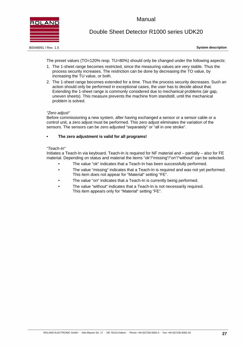
The preset values (TO=120% resp. TU=80%) should only be changed under the following aspects:
1. The 1-sheet range becomes restricted, since the measuring values are very stable. Thus the process security increases. The restriction can be done by decreasing the TO value, by increasing the TU value, or both.
2. The 1-sheet range becomes extended for a time. Thus the process security decreases. Such an action should only be performed in exceptional cases, the user has to decide about that. Extending the 1-sheet range is commonly considered due to mechanical problems (air gap, uneven sheets). This measure prevents the machine from standstill, until the mechanical problem is solved.
“Zero adjust“ Before commissioning a new system, after having exchanged a sensor or a sensor cable or a control unit, a zero adjust must be performed. This zero adjust eliminates the variation of the sensors. The sensors can be zero adjusted “separately“ or “all in one stroke“. • The zero adjustment is valid for all programs!
“Teach-In“ Initiates a Teach-In via keyboard. Teach-In is required for NF material and – partially – also for FE material. Depending on status and material the items “ok“/“missing“/“on“/“without“ can be selected.
• The value “ok“ indicates that a Teach-In has been successfully performed.
• The value “missing“ indicates that a Teach-In is required and was not yet performed. This item does not appear for “Material“ setting “FE“.
• The value “on“ indicates that a Teach-In is currently being performed.
• The value “without“ indicates that a Teach-In is not necessarily required. This item appears only for “Material“ setting “FE“.

Manual
Double Sheet Detector R1000 series UDK20
System description B0048991 / Rev. 1.5
28 ROLAND ELECTRONIC GmbH · Otto-Maurer-Str. 17 · DE 75210 Keltern · Phone +49 (0)7236-9392-0 · Fax +49 (0)7236-9392-33
3.5 Application samples
The following are two typical application examples for the use of the UDK20.
UDK20-x-x-S with one Sensor

Manual
Double Sheet Detector R1000 series UDK20
B0048991 / Rev. 1.5 System description
ROLAND ELECTRONIC GmbH · Otto-Maurer-Str. 17 · DE 75210 Keltern · Phone +49 (0)7236-9392-0 · Fax +49 (0)7236-9392-33 29
UDK20-x-x-S with the Sensor-Switch-Box (SSBUDK10) and four PW42AGS Sensors
Attention Using the Sensor Switch Box is only possible in combination with the UDK20-x-x-S(-FP), but not with the UDK20-2PW-x-x-S(-FP).
The optional Sensor Switch Box (SSB) permits connecting of max. four sensors PW42AGS to one UDK20-x-x-S(-FP). These sensors cannot be operated parallel via SSB but only sequentially via program switchover.
CHANNEL
1 2 3 4
ROLAND ELECTRONIC
SENSOR SWITCH BOX SSB UDK10

Manual
Double Sheet Detector R1000 series UDK20
System description B0048991 / Rev. 1.5
30 ROLAND ELECTRONIC GmbH · Otto-Maurer-Str. 17 · DE 75210 Keltern · Phone +49 (0)7236-9392-0 · Fax +49 (0)7236-9392-33
UDK20-2PW-x-x-S with two PW42AGS Sensors
The switching of the sensors can be made as follows:
a) with the so-called sequencer mode (automatic switching by the unit) b) by program switching

Manual
Double Sheet Detector R1000 series UDK20
B0048991 / Rev. 1.5 System description
ROLAND ELECTRONIC GmbH · Otto-Maurer-Str. 17 · DE 75210 Keltern · Phone +49 (0)7236-9392-0 · Fax +49 (0)7236-9392-33 31
Method a) with the so-called sequencer mode
Advantageous when measuring is the same sheet thickness with each sensor. In contrast to the method b) addressing of each sensor is done automatically by the UDK20. The sequence of the sensors is predetermined in the program.
Advantage: Very fast measurements are possible, smaller software effort on the PLC side.
Disadvantage: There is only 1 "summary output" for the active sensors available. For the summary output the following priorities apply: "2-sheet prior to 0-sheet" and "0-sheet prior to 1-sheet". (For details refer to chapter 6.2.1)
In addition to the selection by sensor number (see system configuration "number of sensors"), the following sequences for the selection are available: Sensor 1 + Sensor 2
Program Thickness Sensor
1 1.5 mm 1, 2
PLC
1. Measuring program 1
2. Analysis result of program 1
1,5 mm1,5 mm

Manual
Double Sheet Detector R1000 series UDK20
Mounting B0048991 / Rev. 1.5
32 ROLAND ELECTRONIC GmbH · Otto-Maurer-Str. 17 · DE 75210 Keltern · Phone +49 (0)7236-9392-0 · Fax +49 (0)7236-9392-33
Method b) with program switching
Meaningful, if the sheets to be monitored by the various sensors have different sheet thicknesses. Also suitable if the nominal thickness changes from cycle to cycle.
For this procedure the respective parameter set (program) must contain nominal thickness and sensor number. The selection of the program is then performed by the PLC.
Disadvantage: A Long time is required for switching the program via the parallel interface.
0.7 mm1.0 mm
Program Thickness Sensor
1 1.0 mm 1
2 0.7 mm 2
PLC
1. Select programm 1
2. Measuring programm 1
3. Analysis result of programm 1
4. Select programm 2
5. Measuring programm 2
6. Analysis result of programm 2

Manual
Double Sheet Detector R1000 series UDK20
B0048991 / Rev. 1.5 Mounting
ROLAND ELECTRONIC GmbH · Otto-Maurer-Str. 17 · DE 75210 Keltern · Phone +49 (0)7236-9392-0 · Fax +49 (0)7236-9392-33 33
4 Mounting
The mounting of the Double Sheet Detector R1000 UDK20 determines the measurement accuracy and the reliability of operation. The system was designed for operating in rough industrial environments. However, the following mounting instructions should be observed in order to minimize mechanical, thermal, and electromagnetic influences on the operation.
4.1 General mounting instructions
The enclosure for wall mounting meets IP65 and is designed for mounting the enclosure close to the sensor location. This results in the use of shorter sensor cables with a corresponding lower exposure to electromagnetic noise and could therefore result in better measurements.
The control unit should be installed in locations where no vibration exists and no additional heat is transferred into the system (even better reduce the heat in the control unit). In addition the control unit should be installed in such a fashion that it can be easily opened for service purposes. During the operation the control unit and the sensors should be under visual control of the operating personnel.
Attention Strong vibrations and additional heat can damage the control unit.
In case of panel or operator consoles the front panel version should be used.

Manual
Double Sheet Detector R1000 series UDK20
Mounting B0048991 / Rev. 1.5
34 ROLAND ELECTRONIC GmbH · Otto-Maurer-Str. 17 · DE 75210 Keltern · Phone +49 (0)7236-9392-0 · Fax +49 (0)7236-9392-33
4.2 Dimensions of the system
4.2.1 System in industrial enclosure
Version UDK20 for one sensor
All dimensions are in mm. Tolerance: ±0.2 mm
Fig. 7: Dimensions of the wall mount enclosure - connection view
125
mm
180 mm
205 mm
140
mm
Mounting holes for screws M4
RS232
SensorSSBcentral plug
80 m
m13
2 m
m
M16
M20

Manual
Double Sheet Detector R1000 series UDK20
B0048991 / Rev. 1.5 Mounting
ROLAND ELECTRONIC GmbH · Otto-Maurer-Str. 17 · DE 75210 Keltern · Phone +49 (0)7236-9392-0 · Fax +49 (0)7236-9392-33 35
Version UDK20-2PW for up to two sensors
All dimensions are in mm. Tolerance: ±0.2 mm
Fig. 8: Dimensions of the wall mount enclosure - front view
125
mm
180 mm
205 mm
140
mm
RS232
Sensor 1Sensor 2
80 m
m
Mounting holes for screws M4
central plug
132
mm
M16
M20

Manual
Double Sheet Detector R1000 series UDK20
Mounting B0048991 / Rev. 1.5
36 ROLAND ELECTRONIC GmbH · Otto-Maurer-Str. 17 · DE 75210 Keltern · Phone +49 (0)7236-9392-0 · Fax +49 (0)7236-9392-33
4.2.2 System with enclosure for front panel mounting
(identically for one and two sensors)
Note For connecting the cables, an installation space of min. 120mm depth must be provided (see illustration on next page).
All dimensions are in mm. Tolerance: ±0.2 mm
Fig. 9: Dimensions of the front panel enclosure -front view
4 x Ø 4,2 for Philips head screw M4 DIN 74
180
160
180
160

Manual
Double Sheet Detector R1000 series UDK20
B0048991 / Rev. 1.5 Mounting
ROLAND ELECTRONIC GmbH · Otto-Maurer-Str. 17 · DE 75210 Keltern · Phone +49 (0)7236-9392-0 · Fax +49 (0)7236-9392-33 37
Lateral view
All dimensions are in mm. Tolerance: ±0.2 mm
Fig. 10: Dimensions of the front panel enclosure -lateral view
130
25
4105
120
50
MountingSpace

Manual
Double Sheet Detector R1000 series UDK20
Mounting B0048991 / Rev. 1.5
38 ROLAND ELECTRONIC GmbH · Otto-Maurer-Str. 17 · DE 75210 Keltern · Phone +49 (0)7236-9392-0 · Fax +49 (0)7236-9392-33
4.3 Mounting of sensors
The reliable function of the Double Sheet Detector depends to a great degree on the correct mounting of the sensors. The following mounting rules should be followed:
• The sensor must be mounted perpendicular to the sheet and fully contact the sheet surface. Foreign matter should not obstruct the contact.
• Tilting or air gaps between the sensor and the sheet surface can result in faulty measurements.
• It is possible to cover the sensor surface with thin Teflon in order to avoid damage to the sheet metal surface. However, this will reduce the performance and is, therefore, not recommended.
• Mounting in steel / distance to magnets
• It is important to set the under gauge threshold of the control unit and analyze the under gauge signal at the 0-sheet output.
• It is important to set the upper gauge threshold of the control unit and analyze the upper gauge signal at the 2-sheet output.
• A spring loaded mounting bracket or the installation directly into the vacuum cup is recommended (see the following sections).
Attention Air gaps can result in faulty measured values. This applies also to tilting or partial gaps or bowed sheets. Ignoring these factors can result in unreliable operations.
The UDK20 can detect unintentional air gaps. The lower limit (“low“) should be used for this purpose.
The lower limit should be adjusted to more than 80%. An air gap causes a decrease of the measured value.
As soon as the measured value falls below the under gauge threshold, then under gauge is signaled at the 0-sheet output.
It is absolutely necessary that the control unit stops the current operation and issue is a fault signal.
Only if this fault condition is eliminated should sheet processing be allowed to continue.
5 mm
5 m
m
X X
X Y
kein Stahlno steel
keine Magneteno magnets
X = Sensordurchmesser Sensor diameter
y = Sensordurchmesser½½ Sensor diameter

Manual
Double Sheet Detector R1000 series UDK20
B0048991 / Rev. 1.5 Mounting
ROLAND ELECTRONIC GmbH · Otto-Maurer-Str. 17 · DE 75210 Keltern · Phone +49 (0)7236-9392-0 · Fax +49 (0)7236-9392-33 39
4.3.1 Checklist for Mounting of contacting Sensors
In the interest of longest lifetime and operational security the following items should be observed when mounting contacting sensors and checked in regular intervals.
Point of attention Possible influences Checked
Cable type 1 Use only the recommended cable with highest flexibility and durability.
Cable routing
2 Avoid any tension of the cable. Route the cable with enough clearance.
3 Special care has to be taken to the route of cable in front of sensor plug, if a flexible sensor bracket is used. The cable should never have a bend close to the plug. Also the meander of the cable has to be symmetrically to the axis of the plug, see enclosed sketch.
Plug 4 Correctly tighten the arresting ring of the plug. This avoids too strong wear of contacts. If possible choose a sensor with fixed cable instead.
Sensor mounting in the destacking tool
5 Use a sensor bracket which is flexible enough to let the sensor align also to tilted sheets. This avoids unnecessary wear of sensor contact surface.
6 Properly adjust sensor edge so that it aligns with the rubber burls of the suction cup. Do not allow excess end. See enclosed sketch. This avoids unnecessary wear of sensor contact surface.
7 Properly adjust sensor mounting in regard to the lifting suction cups of tooling. Do not allow sensor suction cup to excess lifting suction cups. This avoids unnecessary wear of sensor contact surface.
4.3.2 Spring loaded sensor bracket
P-sensors should always be fitted into spring mounted sensor bracket rather than rigid mounting arrangements.
A substantial advantage is in the fact that the sensor presents itself perpendicular to the sheet metal surface even though sensor bracket and sheet surface may not be completely aligned at a right angle.
It is important to observe that lateral cable pull does not tilt the sensor. In addition it must be ensured that the springs do not get stuck. If the springs get stuck tilting of the sensor may result or stuck springs can actually provoke tilting. Ideally the spring mounted bracket should be pre-loaded in order to ensure that the sensor is presented perpendicular to the sheet even under dynamic conditions.
NoppenBurlsSensorkante
Sensor edge
SaugerSuction cup
Sensor
Manual
Double Sheet Detector R1000 series UDK20
Mounting B0048991 / Rev. 1.5
40 ROLAND ELECTRONIC GmbH · Otto-Maurer-Str. 17 · DE 75210 Keltern · Phone +49 (0)7236-9392-0 · Fax +49 (0)7236-9392-33
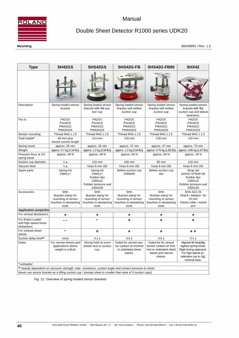
Fig. 11: Overview of spring loaded sensor brackets
Type SH42GS SHS42GS SHS42G-FB SHS42G-FB80 SHX42
Description Spring loaded sensorbracket
Spring loaded sensor-
tion cup
Spring loaded sensorbracket with bellow
suction cup
Spring loaded sensorbracket with bellow
suction cup
Spring loaded sensor
suction cup and lateralclearance.
Fits to P42GSP42AGSPW42GS
PW42AGS
P42GSP42AGSPW42GS
PW42AGS
P42GSP42AGSPW42GS
PW42AGS
P42GSP42AGSPW42GS
PW42AGS
P42GSP42AGSPW42GS
PW42AGS
Sensor mounting Thread M42 x 1.5 Thread M42 x 1.5 Thread M42 x 1.5 Thread M42 x 1.5 Thread M42 x 1.5
Total height* 69 mm plussensor excess length
114 mm 128 mm 128 mm 120 mm
Spring travel approx. 26 mm approx. 26 mm approx. 37 mm approx. 37 mm approx. 70 mm
Weight approx. 0.7 kg (1.54 lbs) approx. 1.2 kg (2.64 lbs) approx. 1.2 kg (2.64 lbs) approx. 0.75 kg (1.65 lbs) approx. 0.85 kg (1.87 lbs)
Pressure force at 1/2spring travel
approx. 48 N approx. 48 N approx. 60 N approx. 60 N approx. 25 N
Suction cup diameter n.a. 110 mm 100 mm 80 mm 110 mm
Vacuum feed n.a. Hose 8 mm OD Hose 8 mm OD Hose 8 mm OD Hose 8 mm OD
Spare parts Spring Kit2395117
Spring Kit2395117
Rubber lips2395110
Rubber pressure pad2395109
Bellow suction cup2395045
Bellow suction cuptbd
Strap setSHX42-STRAP-80
Rubber lips2395110
Rubber pressure pad2395109
Accessories SHKBracket clamp for
mounting of sensorbrackets to destacking
tools
SHKBracket clamp for
mounting of sensorbrackets to destacking
tools
SHKBracket clamp for
mounting of sensorbrackets to destacking
tools
SHKBracket clamp for
mounting of sensorbrackets to destacking
tools
SHX-AZ2-25Shank / Adaptor for
25 mmClamp collar / swivel
arm
Application properties
For vertical destackers + + + + +For Robot-Loaderand high-speed lineardestackers
+ + +
For inclined sheetstacks
o + + + +
Suction delay time** none 0.1 s 0.5 s 0.5 s 0.1 s
Notes For narrow sheets andapplications where
weight is critical
Strong hold on evensheets due to suction
cup.
Suited for utmost sen-sor contact on inclined
or ondulated sheetstacks.
Suited for for utmostsensor contact on incli-ned or ondulated sheet
stacks and narrowsheets.
highest spring travel.Rigid during approach.
For high lateral ac-celeration (up to 2g),
minimal wear.
* unloaded
** heavily dependent on vaccuum strength, tube resistance, contact angle and contact pressure to sheet
Never use sensor bracket as a lifting suction cup ! (except sheet is smaller than area of 3 suction cups)

Manual
Double Sheet Detector R1000 series UDK20
B0048991 / Rev. 1.5 Mounting
ROLAND ELECTRONIC GmbH · Otto-Maurer-Str. 17 · DE 75210 Keltern · Phone +49 (0)7236-9392-0 · Fax +49 (0)7236-9392-33 41
4.3.2.1 Spring loaded sensor bracket SH42GS
Fig. 12: Spring loaded sensor bracket SH42GS
66
"A"
57
Hub
max
.65
min
.25
98
10Ø
View in direction "A"without sensor
ø20.5
30O
50
110
8045°
120°
75°
40
90
Sensor
movable
fixed
All Dimensions are in mm. Tolerance: ±0.4 mm.

Manual
Double Sheet Detector R1000 series UDK20
Mounting B0048991 / Rev. 1.5
42 ROLAND ELECTRONIC GmbH · Otto-Maurer-Str. 17 · DE 75210 Keltern · Phone +49 (0)7236-9392-0 · Fax +49 (0)7236-9392-33
4.3.3 Spring loaded sensor bracket with flat suction cup
Destacking of blanks is done mostly with the vacuum suction cups. For the measurement of the sheet thickness the sensors should rest vertically and flat on the sheet. The best contact to the sheet surface is made by mounting the sensor into a vacuum suction cup.
That suction cups present the sensor vertically to the sheet surface and function fast because of the low volume of air required. Deviations from the right angle have to be compensated by the spring-loaded Sensor brackets; otherwise no vacuum can be generated. Bellow style vacuum suction cups can themselves compensate deviations from the right angle but they can also pull an inclined sensor to the sheet surface or in inclined sheet to the sensor leading to instability of measurement. The forces acting in this process can lead to wear and tear to the bracket and lips of the suction cups. Generating and releasing vacuum requires considerably longer time.
The suction cups are not designed to lift and carry the sheet. In order to prevent inadvertently the sensor losing touch to the sheet it is necessary to maintain a certain degree of spring load between sensor and sheet. Sensor cable and vacuum hoses should be mounted in such a fashion that low angular forces act on the sensor bracket. If necessary the sensor thread can be sealed with a permanently elastic sealant (Hylomar, Loctite) or a narrow Teflon web.
The spring-loaded sensor bracket contains fixing holes to attach the bracket to the carrying tooling. In special cases (on request) is an operation without the vacuum cup or the lifting/carrying of the sheet with the sensor bracket possible.
4.3.3.1 Spring travel of SHS42GS
Fig. 13: Spring travel for SHS42GS
674
6
ausgefedert (Zug)extracted (pull)
54
46
unbelastetunstressed
26
46
eingefedert (Druck)retracted (pressure)

Manual
Double Sheet Detector R1000 series UDK20
B0048991 / Rev. 1.5 Mounting
ROLAND ELECTRONIC GmbH · Otto-Maurer-Str. 17 · DE 75210 Keltern · Phone +49 (0)7236-9392-0 · Fax +49 (0)7236-9392-33 43
4.3.3.2 Spring loaded sensor bracket SHS42GS with flat suction cup
The spring loaded sensor bracket SHS42GS with flat suction cup is intended for accommodating the sensors. It is well suitable for use in feeder destacking applications (only vertical motions, no turning motions). For usage with robotic destackers the sensor bracket SHS42G-FB (with bellow suction cup) is to be preferred.
All Dimensions are in mm. Tolerance: ± 0.4 mm.
Fig. 14: Spring loaded sensor bracket SHS42GS with flat suction cup
Clamping bracket SHK
110
Spring loaded sensor bracket
Sensor
65
6
ø25
25
94
M8
Rubber nipples
Sensor edge
Sensor
Suction cup
"A"
40
300
orcu
sto
mm
ade
98
40
Connection 1/4"
View in direction "A"without clamping bracket
ø20.5
30O
50
110
8045°
120°
75°
4090
see fig.“Spring travel”

Manual
Double Sheet Detector R1000 series UDK20
Mounting B0048991 / Rev. 1.5
44 ROLAND ELECTRONIC GmbH · Otto-Maurer-Str. 17 · DE 75210 Keltern · Phone +49 (0)7236-9392-0 · Fax +49 (0)7236-9392-33
4.3.4 Spring mounted sensor holder SHX42
Features:
• Very stiff in extended condition, for lateral acceleration up to 2g. Thus precise putting on the sheet without canting, also on splayed sheets or bevelled TWB stacks.
• Very elastic in pressed condition and movable into all directions. Lateral motions of the sheet being transported can thereby also be compensated up to approx. ±1 centimetre.
• No appearance of lateral forces, thus only minimal wear.
• Fast suction and releasing of the sheets due to small air volume under the suction hood, compared to bellows suction cups.
• Same sealing gasket and burled plate as used with the Roland SHS42GS.
• Good access to the sensor from above, no counter-nut required.
• Fixing of sensor by lateral headless screw with plastic pressure pad.
Fix the sensor holder by using at least 2 of the M8 tap holes in the mounting plate. If required, use a ball clamp mount of 28 … 32 mm for Omni directional adjustment to the sheet surface (e.g. Norgren Co., Springer Co.).
Lubricate the sensor thread very sparingly. Screwing the sensor from above until the sensor face is positioned at half the height of the rubber burls. If the thread needs to be vacuum-tight, screw-in the thread turns by using a permanently elastic sealing agent (Hylomar, Loctite). Fix sensor with the set screw (M6).
Adjust the holder to a position lower than the suction cups carrying the sheet. When the sensor is put on the sheet the holder must comply so much that (after being lifted) it remains pressed for at least 10mm, for providing the necessary freedom for the belts. Only then the required compliance is achieved. The holder may not carry loads. Only small, light weighted parts can be directly transported with the sensor holder.
Fig. 15: Sensor bracket SHX42
150
110 Ø
max
. 12
0

Manual
Double Sheet Detector R1000 series UDK20
B0048991 / Rev. 1.5 Mounting
ROLAND ELECTRONIC GmbH · Otto-Maurer-Str. 17 · DE 75210 Keltern · Phone +49 (0)7236-9392-0 · Fax +49 (0)7236-9392-33 45
Fig. 16: Base plate for sensor bracket SHX42
Replacing the gasket
Pull the rubber disc over the lower edge. Pay attention for undamaged sealing lips at the inner and outer edge as well as for uniform projection of the sealing edge.
The gasket can be bilaterally used.

Manual
Double Sheet Detector R1000 series UDK20
Mounting B0048991 / Rev. 1.5
46 ROLAND ELECTRONIC GmbH · Otto-Maurer-Str. 17 · DE 75210 Keltern · Phone +49 (0)7236-9392-0 · Fax +49 (0)7236-9392-33
4.3.4.1 Clamping bracket SHX-AZ2-25
For fixing the sensor bracket SHX42 to swivel arms with 25 mm clamp collar.
Fig. 17: Clamping bracket SHX-AZ2-25

Manual
Double Sheet Detector R1000 series UDK20
B0048991 / Rev. 1.5 Mounting
ROLAND ELECTRONIC GmbH · Otto-Maurer-Str. 17 · DE 75210 Keltern · Phone +49 (0)7236-9392-0 · Fax +49 (0)7236-9392-33 47
4.3.5 Spring loaded sensor bracket SHS42G-FB (with bellow suction cup)
The spring loaded sensor bracket SHS42G-FB with bellow suction cup is intended for the installation of the P sensor. It is well suitable for use in robotic destackers, since transversal forces (appearing on fast turning motions) are well compensated.
The suction vacuum and the integrated nap ring assure a full-area pressure contact of sensor and sheet.
The suction cup has a Shore hardness of 45 (red), harder suction cups with a Shore hardness of 60 (black) are available (see chapter 12 „Order data - sensors and accessories).
On installing, attention must be paid that the sensor is thoroughly sealed (e.g. with Teflon tape) in the thread seating.
Considerations:
• The sensor face must align with the naps.
• The vacuum must adequately effect.
• The suction facility must be kept free from loading, i.e. the springs may only be low pre-tensioned.
• The suction facility must not be used as load-lifting device.
Fig. 18: Sensor bracket SHS42G-FB
: unloaded 128 ± 1
: unloaded 90 ± 1
: Spring travel: appr. 37
enclosed:swingable angular connectionfor hoseinner Ø6mm, outerØ8 mm
1
2
3
60,5
39,5
69,5
33 Ø21
Ø84,5M42x1,5
10x45,0 °
M42x1,5
110
130
7050
A-A
38
65,5
Ø10
2
Ø85
15
Ø99
20
Ø8

Manual
Double Sheet Detector R1000 series UDK20
Mounting B0048991 / Rev. 1.5
48 ROLAND ELECTRONIC GmbH · Otto-Maurer-Str. 17 · DE 75210 Keltern · Phone +49 (0)7236-9392-0 · Fax +49 (0)7236-9392-33
4.3.6 Clamping bracket SHK
The clamping bracket SHK can be used for the mounting of the spring loaded sensor brackets SHS...GS or SH...GS.
All Dimensions are in mm. Tolerance: ± 0.2 mm.
Fig. 19: Clamping bracket SHK
25
94
M20
M8
21
40
95
3
95
orcu
stom
mad
e
.
.
5
5

Manual
Double Sheet Detector R1000 series UDK20
B0048991 / Rev. 1.5 Mounting
ROLAND ELECTRONIC GmbH · Otto-Maurer-Str. 17 · DE 75210 Keltern · Phone +49 (0)7236-9392-0 · Fax +49 (0)7236-9392-33 49
4.3.7 Incorrect mounting of the PW sensors
The following illustration shows examples of incorrect installations of PW-sensors.
Faulty!
The sensor does not touch the sheet.
Faulty!
The sensor does not sit perpendicular on the sheet, the sensor bracket is apparently not suitable.
Faulty!
An air gap exists between the first and the second sheet. The sensor is mounted in an unfavorable position.
Faulty!
An air gap exists between the first and the second sheet. The second sheet clings to the first sheet, perhaps by stamping residuals.
Faulty!
Fault prone control in a bucket. An air gap exists between bended sheets.
Fig. 20: Incorrect mounting of the PW-sensors

Manual
Double Sheet Detector R1000 series UDK20
Mounting B0048991 / Rev. 1.5
50 ROLAND ELECTRONIC GmbH · Otto-Maurer-Str. 17 · DE 75210 Keltern · Phone +49 (0)7236-9392-0 · Fax +49 (0)7236-9392-33
4.3.8 Electromagnetic interference
Electromagnetic interference can affect the measuring accuracy of the sensor. Therefore the sensors should not be installed close to devices which cause electromagnetic interference. Such devices are e.g. frequency converters, servo motors or proximity switches on inductive basis. In case of switching magnets a minimum distance of 20 mm should be observed in order to avoid feedback. The sensor cables should not be placed directly adjacent to cables with large interference potential, e.g. power supply cable. This applies especially to longer cable lengths.
4.3.9 Mounting of the Sensor-Switch-Box SSBUDK10
Note The Sensor-Switch-Box SSBUDK10 should be installed in locations where no vibration exists and no additional heat is transferred into the system (even better reduce the heat in the control unit). Furthermore, the Sensor-Switch-Box must be installed such that it is always accessible and can be easily opened for service purposes. During the operation the Sensor-Switch-Box and the sensors should be under visual control of the operating personnel.
All Dimensions are in mm. Tolerance: ± 0.4 mm.
Fig. 21: Sensor-Switch-Box SSBUDK10

Manual
Double Sheet Detector R1000 series UDK20
B0048991 / Rev. 1.5 Mounting
ROLAND ELECTRONIC GmbH · Otto-Maurer-Str. 17 · DE 75210 Keltern · Phone +49 (0)7236-9392-0 · Fax +49 (0)7236-9392-33 51
4.4 Automatic tool changer
The Roland sensors can be used within an ATC concept (Automatic tool change).
The only requirements we have established are:
Every sensor signal must have its own contact.
The contacts must be low resistive (only gold contacts!).
The contacts must be suited for peak currents of 2 ampere.
The shielding of the cable must not be interrupted and therefore have its own contact.
The contacts must be protected from contamination.
Do not route the cable together with other cables leading high currents.
Die metallic parts of the tooling have to be grounded.
It is not allowed to open the connector during the measuring operation.
After each tool change it is required to perform a zero set command.
Attention Incorrect wiring may destroy the control unit or the sensor.

Manual
Double Sheet Detector R1000 series UDK20
Mounting B0048991 / Rev. 1.5
52 ROLAND ELECTRONIC GmbH · Otto-Maurer-Str. 17 · DE 75210 Keltern · Phone +49 (0)7236-9392-0 · Fax +49 (0)7236-9392-33
Blank page

Manual
Double Sheet Detector R1000 series UDK20
B0048991 / Rev. 1.5 Electrical installation
ROLAND ELECTRONIC GmbH · Otto-Maurer-Str. 17 · DE 75210 Keltern · Phone +49 (0)7236-9392-0 · Fax +49 (0)7236-9392-33 53
5 Electrical installation
5.1 General instructions
The sensor cables should be kept as short as possible in order to minimize the influence of electromagnetic noise. Cable shields must be connected according to the connection diagrams only and should not have any additional connections.
Attention Damaged cable installations can result in additional electrical connections. This can disturb the measured values.
5.2 Configuration of connectors
UDK20-xx-S in industrial enclosure

Manual
Double Sheet Detector R1000 series UDK20
Electrical installation B0048991 / Rev. 1.5
54 ROLAND ELECTRONIC GmbH · Otto-Maurer-Str. 17 · DE 75210 Keltern · Phone +49 (0)7236-9392-0 · Fax +49 (0)7236-9392-33
UDK20-xx-S-FP as front plate mount
A Central connector (front plate mount: terminal strips for direct connection)
B Connector for RS232 interface
C Connector for sensor
D Connector for sensor switch box
UDK20-2PW-xx-S in industrial enclosure

Manual
Double Sheet Detector R1000 series UDK20
B0048991 / Rev. 1.5 Electrical installation
ROLAND ELECTRONIC GmbH · Otto-Maurer-Str. 17 · DE 75210 Keltern · Phone +49 (0)7236-9392-0 · Fax +49 (0)7236-9392-33 55
UDK20-2PW-xx-S-FP as front plate mount
A Central connector (front plate mount: terminal strips for direct connection)
B Connector for RS232 interface
C1 Connector for sensor 1
C2 Connector for sensor 2

Manual
Double Sheet Detector R1000 series UDK20
Electrical installation B0048991 / Rev. 1.5
56 ROLAND ELECTRONIC GmbH · Otto-Maurer-Str. 17 · DE 75210 Keltern · Phone +49 (0)7236-9392-0 · Fax +49 (0)7236-9392-33
5.2.1 Sensor connection - 1st sensor
Connection of the 1st sensor to the control unit with the cable "SCPWS-GG or SCPWS-GW".
Sensor cable pin Meaning Colour of wire Terminal no. of control unit
Pin 1 W-In 1 grey 23
Pin 2 W-In 2 pink 24
Pin 3 +12 VDC red 19
Pin 4 0 VDC black (black/violet in sensor cable) 20
Pin 5 -12 VDC blue 22
Pin 6 P-line 1 brown 1 mm² 27
Pin 7 W-Out 1 brown 25
Pin 8 P-line 2 white 1 mm² 28
Pin 9 W-Out 2 white 26
1234
56879
2324
2526
22
1920
2728
greypinkredblackvioletbluebrown *white *browngreen
UD
K20
1234
56879
Sen
so
rP
W42
AG
S
Sensorplug
* 1 mm²

Manual
Double Sheet Detector R1000 series UDK20
B0048991 / Rev. 1.5 Electrical installation
ROLAND ELECTRONIC GmbH · Otto-Maurer-Str. 17 · DE 75210 Keltern · Phone +49 (0)7236-9392-0 · Fax +49 (0)7236-9392-33 57
5.2.2 Sensor connection – 2nd sensor
The connection for the 2nd sensor is only present at unit versions UDK20-2PW-x-x-S(-FP), but not at unit versions UDK20-x-x-S(-FP).
Connection of the sensor to the control unit with the cable "SCPWS-GG or SCPWS-GW".
Sensor cable pin Meaning Colour of wire Terminal no. of control unit
Pin 1 W-In 1 grey 43
Pin 2 W-In 2 pink 44
Pin 3 +12 VDC red 40
Pin 4 0 VDC black (black/violet in sensor cable) 41
Pin 5 -12 VDC blue 42
Pin 6 P-line 1 brown 1 mm² 47
Pin 7 W-Out 1 brown 45
Pin 8 P-line 2 white 1 mm² 48
Pin 9 W-Out 2 white 46
1234
56879
greypinkredblackvioletbluebrown *white *browngreen
UD
K20
1234
56879
Sen
so
rP
W42
AG
S
43444041
4247484546
Sensorplug
* 1 mm²

Manual
Double Sheet Detector R1000 series UDK20
Electrical installation B0048991 / Rev. 1.5
58 ROLAND ELECTRONIC GmbH · Otto-Maurer-Str. 17 · DE 75210 Keltern · Phone +49 (0)7236-9392-0 · Fax +49 (0)7236-9392-33
5.2.3 Connection of Sensor Switch Box
The connection for the sensor switch box is only present at unit versions UDK20-x-x-S(-FP), but not at unit versions UDK20-2PW-x-x-S(-FP).
Connection of the sensor to the Sensor-Switch-Box with the cable „SVCPWS-SSBUDK10“.
Sensor cable pin Meaning Colour of wire Terminal no. of control unit
Pin 1 Switching-over signal 1 white 29
Pin 2 Switching-over signal 2 green 30
Pin 3 Control signal brown 31
Pin 4 0 VDC yellow 32
Pin 5 +24 VDC grey 33
Plug enclosure Cable shield (both-sided)
1
2
3
4
5
1
2
3
4
5
Se
ns
or-
Sw
itc
h-B
ox
SS
BU
DK
10
29
30
31
32
33grey
white
brown
green
yellow

Manual
Double Sheet Detector R1000 series UDK20
B0048991 / Rev. 1.5 Electrical installation
ROLAND ELECTRONIC GmbH · Otto-Maurer-Str. 17 · DE 75210 Keltern · Phone +49 (0)7236-9392-0 · Fax +49 (0)7236-9392-33 59
5.2.4 Connection of RS232
The RS232 connection is installed in C version units only.
The interface cable „SM8KRS232D9S“ belongs to the scope of supply.
Connections at control unit Manufacturer / types / notes
RS232
View: plug side
M8, 3-pin, female connector at control unit
Binder type 768 and others
pin 1 GND
pin 2 RXD
pin 3 TXD
Shield / ground Internal at enclosure (common)
Cable SM8KRS232D9S:
X = shield connection at cable receptacle
Fig. 22: Cable SM8KRS232D9S
Warning When connecting or disconnecting the sensor plug you must stop measurement! Non-observance can result in a damage of the sensor!
3
RXD - 2
TXD - 3
5
3
2
1
2
3
4
5
6
7
8
9
Kabellänge 3 mCable length 3m
X
3

Manual
Double Sheet Detector R1000 series UDK20
Electrical installation B0048991 / Rev. 1.5
60 ROLAND ELECTRONIC GmbH · Otto-Maurer-Str. 17 · DE 75210 Keltern · Phone +49 (0)7236-9392-0 · Fax +49 (0)7236-9392-33
5.2.5 Connection of Central plug
The supply voltage as well as the PLC inputs / outputs are connected via the central plug.
Fig. 23: Central plug
5.2.5.1 Connection to Machine grounding
The control unit must be connected to the central machine grounding by a cable with a cross-section of at least 1,5 mm²
Attention The positive supply voltage +24 VDC should not be connected to machine ground.
5.2.5.2 Supply voltage cable
The voltage supply cable should be kept short. Up to 20 m length use cable leads with 2 x 1 mm² cross-section. For larger lengths the cross section should be increased.
Attention The positive supply voltage +24 VDC should not be connected to machine ground.

Manual
Double Sheet Detector R1000 series UDK20
B0048991 / Rev. 1.5 Electrical installation
ROLAND ELECTRONIC GmbH · Otto-Maurer-Str. 17 · DE 75210 Keltern · Phone +49 (0)7236-9392-0 · Fax +49 (0)7236-9392-33 61
5.2.5.3 Data inputs / outputs to PLC
Version B with relay outputs
At front panel units there is no central plug. The connection is made via terminal blocks.
Attention The positive supply voltage +24 VDC should not be connected to machine ground.
Dat
aIn
Da
taO
ut
PLC
System test
Measurement Start Bit 0
Bit 1
Bit 2
Bit 3
Bit 4
Bit 7
Bit 6
Bit 5
(Teach-In)
(Zero adjust)
Measurement menue select
Enable
2-sheet
1-sheet
0-sheet
Shield LiYCY 15 x 0.25 mm²
Out 0
Enable
Out 1
2-sheet
Out 2
1-sheet
Out 3
0-sheet
A1
A2
A3
A4
A5
A6
A7
A8
A9
C1
C2
C3
C4
C5
C6
C7
C8
C9
B2
B3
B4
B5
B6
B7
B8
Externalpower supply
+ 24 VDC
0 VDC
8
5
6
7
38
37
36
35
4
9
10
12
14
16
17
18
34
IN0
IN1
IN2
IN3
IN4
IN5
IN6
IN7
IN8
+ 24 VDC
0 VDC
Central machine ground
plugUDK20
min. 1 mm²
min. 1 mm²
min. 1.5 mm²
39
PLC earth ground
Central
0 VDC from PLC
+24 VDC from PLC
0 VDC from PLC
0 VDC from PLC
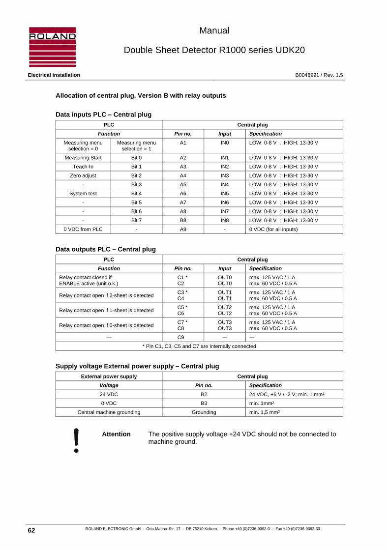
Manual
Double Sheet Detector R1000 series UDK20
Electrical installation B0048991 / Rev. 1.5
62 ROLAND ELECTRONIC GmbH · Otto-Maurer-Str. 17 · DE 75210 Keltern · Phone +49 (0)7236-9392-0 · Fax +49 (0)7236-9392-33
Allocation of central plug, Version B with relay outputs
Data inputs PLC – Central plug
PLC Central plug
Function Pin no. Input Specification Measuring menu
selection = 0 Measuring menu
selection = 1 A1 IN0 LOW: 0-8 V ; HIGH: 13-30 V
Measuring Start Bit 0 A2 IN1 LOW: 0-8 V ; HIGH: 13-30 V
Teach-In Bit 1 A3 IN2 LOW: 0-8 V ; HIGH: 13-30 V
Zero adjust Bit 2 A4 IN3 LOW: 0-8 V ; HIGH: 13-30 V
- Bit 3 A5 IN4 LOW: 0-8 V ; HIGH: 13-30 V
System test Bit 4 A6 IN5 LOW: 0-8 V ; HIGH: 13-30 V
- Bit 5 A7 IN6 LOW: 0-8 V ; HIGH: 13-30 V
- Bit 6 A8 IN7 LOW: 0-8 V ; HIGH: 13-30 V
- Bit 7 B8 IN8 LOW: 0-8 V ; HIGH: 13-30 V
0 VDC from PLC - A9 - 0 VDC (for all inputs)
Data outputs PLC – Central plug
PLC Central plug
Function Pin no. Input Specification Relay contact closed if ENABLE active (unit o.k.)
C1 * C2
OUT0 OUT0
max. 125 VAC / 1 A max. 60 VDC / 0.5 A
Relay contact open if 2-sheet is detected C3 * C4
OUT1 OUT1
max. 125 VAC / 1 A max. 60 VDC / 0.5 A
Relay contact open if 1-sheet is detected C5 * C6
OUT2 OUT2
max. 125 VAC / 1 A max. 60 VDC / 0.5 A
Relay contact open if 0-sheet is detected C7 * C8
OUT3 OUT3
max. 125 VAC / 1 A max. 60 VDC / 0.5 A
--- C9 --- ---
* Pin C1, C3, C5 and C7 are internally connected
Supply voltage External power supply – Central plug
External power supply Central plug
Voltage Pin no. Specification 24 VDC B2 24 VDC, +6 V / -2 V; min. 1 mm²
0 VDC B3 min. 1mm²
Central machine grounding Grounding min. 1,5 mm²
Attention The positive supply voltage +24 VDC should not be connected to machine ground.

Manual
Double Sheet Detector R1000 series UDK20
B0048991 / Rev. 1.5 Electrical installation
ROLAND ELECTRONIC GmbH · Otto-Maurer-Str. 17 · DE 75210 Keltern · Phone +49 (0)7236-9392-0 · Fax +49 (0)7236-9392-33 63
Version B or C with opto coupler outputs
At front panel units there is no central plug. The connection is made via terminal blocks.
Attention The positive supply voltage +24 VDC should not be connected to machine ground.
Dat
aIn
Da
taO
ut
PLC
System test
(Teach-In)
Enable
2-sheet
1-sheet
0-sheet
Shield LiYCY 15 x 0.25 mm²
A1
A2
A3
A4
A5
A6
A7
A8
external power supply
+ 24 VDC
0 VDC
IN8
+ 24 VDC
0 VDC
UDK20
Measurement Start
Meas menue select.
(Zero adjust)
Central machine ground
min. 1 mm²
min. 1 mm²
min. 1.5 mm²
Centralplug
1-sheet
2-sheet
0-sheet
0 VDC from PLC
+24 VDC from PLC
0 VDC from PLC
0 VDC from PLC
*max. 50 VDC / 100 mA

Manual
Double Sheet Detector R1000 series UDK20
Electrical installation B0048991 / Rev. 1.5
64 ROLAND ELECTRONIC GmbH · Otto-Maurer-Str. 17 · DE 75210 Keltern · Phone +49 (0)7236-9392-0 · Fax +49 (0)7236-9392-33
Allocation of central plug, Version B or C with opto coupler outputs
Data inputs PLC – Central plug
PLC Central plug
Function Pin no. Input Specification Measuring menu
selection = 0 Measuring menu
selection = 1 A1 IN0 LOW: 0-8 V ; HIGH: 13-30 V
Measuring Start Bit 0 A2 IN1 LOW: 0-8 V ; HIGH: 13-30 V
Teach-In Bit 1 A3 IN2 LOW: 0-8 V ; HIGH: 13-30 V
Zero adjust Bit 2 A4 IN3 LOW: 0-8 V ; HIGH: 13-30 V
- Bit 3 A5 IN4 LOW: 0-8 V ; HIGH: 13-30 V
System test Bit 4 A6 IN5 LOW: 0-8 V ; HIGH: 13-30 V
- Bit 5 A7 IN6 LOW: 0-8 V ; HIGH: 13-30 V
- Bit 6 A8 IN7 LOW: 0-8 V ; HIGH: 13-30 V
- Bit 7 B8 IN8 LOW: 0-8 V ; HIGH: 13-30 V
0 VDC from PLC - A9 - 0 VDC (for all inputs)
Data outputs PLC – Central plug
PLC Central plug
Function Pin no. Input Specification Opto coupler low resistant if ENABLE active (unit o.k.)
C1 * C2
+ OUT0 - OUT0
+ -
Opto coupler high resistance if 2-sheet is detected
C3 * C4
+ OUT1 - OUT1
+ -
Opto coupler high resistance if 1-sheet is detected
C5 * C6
+ OUT2 - OUT2
+ -
Opto coupler high resistance if 0-sheet is detected
C7 * C8
+ OUT3 - OUT3
+ -
--- C9 --- ---
Output current: absolute max. 150 mA / continuously max. 100 mA; max. 50 VDC
* Pin C1, C3, C5 and C7 are internally connected
Supply voltage External power supply – Central plug
External power supply Central plug
Voltage Pin no. Specification 24 VDC B2 24 VDC, +6 V / -2 V; min. 1 mm²
0 VDC B3 min. 1mm²
Central machine grounding Grounding min. 1,5 mm²
Attention The positive supply voltage +24 VDC should not be connected to machine ground.

Manual
Double Sheet Detector R1000 series UDK20
B0048991 / Rev. 1.5 Electrical installation
ROLAND ELECTRONIC GmbH · Otto-Maurer-Str. 17 · DE 75210 Keltern · Phone +49 (0)7236-9392-0 · Fax +49 (0)7236-9392-33 65
5.3 Connecting diagram - examples
5.3.1 Connecting diagram UDK20 with one sensor
1 Cable
Order no.: SCPWS-GG (straight cable socket) Order no.: SCPWS-GW (90° angle socket)
Superflex (C)Y PURKOMBI 2 x 1,0 mm² + 4 x 2 x 0,25 mm²
1a Cable plug (9 contacts)
Order no.: 2277004
Pin 1 grey Pin 2 pink Pin 3 red Pin 4 black Pin 5 blue Pin 6 brown, 1 mm² Pin 7 brown Pin 8 white, 1 mm² Pin 9 green Enclosure blank (Shield)
1b Cable socket (9 contacts)
Order no.: 2276005 (straight) 2276007 (90° angle)
Pin 1 grey Pin 2 pink Pin 3 red Pin 4 black Pin 5 blue Pin 6 brown, 1 mm² Pin 7 brown Pin 8 white, 1 mm² Pin 9 green Enclosure blank (Shield)
Optional disconnection point
When a disconnection point is requested then 2 cables of type SCPWS-xx can be directly connected!
Fig. 24: UDK20 with one PW42AGS sensor
1
1b
1a
1
1b
Optional
disconnection
point

Manual
Double Sheet Detector R1000 series UDK20
Electrical installation B0048991 / Rev. 1.5
66 ROLAND ELECTRONIC GmbH · Otto-Maurer-Str. 17 · DE 75210 Keltern · Phone +49 (0)7236-9392-0 · Fax +49 (0)7236-9392-33
5.3.2 Connecting diagram UDK20 with SSBUDK10 and four sensors
1 Cable 2 Cable
Order no.: SCPWS-GG (straight cable socket) Order no.: SCPWS-GW (90° angle socket)
Order no.: SVCPWS-SSBUDK10
Superflex (C)Y PURKOMBI 2 x 1,0 mm² + 4 x 2 x 0,25 mm²
1a Cable plug (9 contacts) 2a Cable plug (5 contacts)
Order no.: 2277004 Order no.: 2277010
Pin 1 grey Pin 2 pink Pin 3 red Pin 4 black Pin 5 blue Pin 6 brown, 1 mm² Pin 7 brown Pin 8 white, 1 mm² Pin 9 green Enclosure blank (Shield)
Pin 1 white Pin 2 green Pin 3 brown Pin 4 yellow Pin 5 grey Enclosure blank (Shield)
1b Cable socket (9 contacts) 2b Cable socket (5 contacts)
Order no.: 2276005 (straight) 2276007 (90° angle)
Order no.: 2276010
Pin 1 grey Pin 2 pink Pin 3 red Pin 4 black Pin 5 blue Pin 6 brown, 1 mm² Pin 7 brown Pin 8 white, 1 mm² Pin 9 green Enclosure blank (Shield)
Pin 1 white Pin 2 green Pin 3 brown Pin 4 yellow Pin 5 grey Enclosure blank (Shield)
Fig. 25: UDK20 with SSBUDK10 and four PW42AGS sensors
1b
1a1a1a1a
1b
1b 1b
1 1 1
1a 1b2a 2b
2
1
POWER
CHANNEL
1 2 3 4
ROLAND ELECTRONIC
SENSOR SWITCH BOX SSB UDK10

Manual
Double Sheet Detector R1000 series UDK20
B0048991 / Rev. 1.5 Electrical installation
ROLAND ELECTRONIC GmbH · Otto-Maurer-Str. 17 · DE 75210 Keltern · Phone +49 (0)7236-9392-0 · Fax +49 (0)7236-9392-33 67
5.3.3 Connecting diagram UDK20-2PW with two sensors
1 Cable
Order no.: SCPWS-GG (straight cable socket) Order no.: SCPWS-GW (90° angle socket)
Superflex (C)Y PURKOMBI 2 x 1,0 mm² + 4 x 2 x 0,25 mm²
1a Cable plug (9 contacts)
Order no.: 2277004
Pin 1 grey Pin 2 pink Pin 3 red Pin 4 black Pin 5 blue Pin 6 brown, 1 mm² Pin 7 brown Pin 8 white, 1 mm² Pin 9 green Enclosure blank (Shield)
1b Cable socket (9 contacts)
Order no.: 2276005 (straight) 2276007 (90° angle)
Pin 1 grey Pin 2 pink Pin 3 red Pin 4 black Pin 5 blue Pin 6 brown, 1 mm² Pin 7 brown Pin 8 white, 1 mm² Pin 9 green Enclosure blank (Shield)
Optional disconnection point
When a disconnection point is requested then 2 cables of type SCPWS-xx can be directly connected!
Fig. 26: UDK20-2PW with two PW42AGS sensors
1
1b
1a
1
1b
Optional
disconnection
point

Manual
Double Sheet Detector R1000 series UDK20
Communication with the PLC B0048991 / Rev. 1.5
68 ROLAND ELECTRONIC GmbH · Otto-Maurer-Str. 17 · DE 75210 Keltern · Phone +49 (0)7236-9392-0 · Fax +49 (0)7236-9392-33
5.4 Internal wiring of the Sensor-Switch-Box SSBUDK10
X1, X3, X4, X5 und X6 Meaning Colour of wire
Pin 1 W-In 1 grey
Pin 2 W-In 2 pink
Pin 3 + 12 VDC red
Pin 4 0 VDC black (black/violet in sensor cable)
Pin 5 - 12 VDC blue
Pin 6 P-line 1 brown, 1 mm²
Pin 7 W-Out 1 brown
Pin 8 P-line 2 white, 1 mm²
Pin 9 W-Out 2 green
X2 Meaning Colour of wire
Pin 1 Switch-over signal 1 white
Pin 2 Switch-over signal 2 green
Pin 3 Control signal brown
Pin 4 0 VDC yellow
Pin 5 + 24 VDC grey
Fig. 27: Internal wiring of the Sensor-Switch-Box SSBUDK10
41 42 43 44 45
gre
y
wh
ite
gre
en
ye
llow
bro
wn
504947 48 55 5554535251 26 27 2928 3021 22 23 24 25 36 37 3938 4031 32 33 34 35
6 7 98 101 2 3 4 5 16 17 1918 2011 12 13 14 15
gre
y
pin
k
red
bla
ck
blu
e
bro
wn
, 1
mm
²
wh
ite,
1 m
m²
bro
wn
gre
en
to X2 to X3 to X4
to X1 to X5 to X6
X1X2
X3 X4 X5 X6
X7
gre
y
pin
k
red
bla
ck
blu
e
bro
wn
, 1
mm
²
wh
ite,
1 m
m²
bro
wn
gre
en
gre
y
pin
k
red
bla
ck
blu
eb
row
n,
1 m
m²
wh
ite,
1 m
m²
bro
wn
gre
en
gre
y
pin
k
red
bla
ck
blu
e
bro
wn
, 1
mm
²
wh
ite,
1 m
m²
bro
wn
gre
en
gre
en
wh
ite,
1 m
m²
bro
wn
bro
wn
, 1
mm
²
blu
e
gre
y
pin
k
red
bla
ck

Manual
Double Sheet Detector R1000 series UDK20
B0048991 / Rev. 1.5 Communication with the PLC
ROLAND ELECTRONIC GmbH · Otto-Maurer-Str. 17 · DE 75210 Keltern · Phone +49 (0)7236-9392-0 · Fax +49 (0)7236-9392-33 69
6 Communication with the PLC
The UDK20 has 9 potential-free, galvanically insulated (opto coupled) inputs. For the 4 outputs there are relays or opto couplers available as alternatives.
6.1 PLC inputs
For external control parallel PLC inputs are available. These inputs can be operated via a PLC. If several functions are executed at the same time, then the unit issues an fault message. The following functions are possible:
• Measurement Start / Stop
• System test
• Menu selection
• Teach-In (not active as factory adjustment)
• Zero adjust (not active as factory adjustment)
6.2 PLC output signals
The following signals are available as outputs:
Opto coupler outputs
Signal Meaning Note
OUT3 0-sheet output Standard 0 V active (selectable in system configuration)
OUT2 1-sheet output Standard 0 V active (selectable in system configuration)
OUT1 2-sheet output Standard 0 V active (selectable in system configuration)
OUT0 ENABLE output Standard 24 V active (not selectable, for safety reasons)

Manual
Double Sheet Detector R1000 series UDK20
Communication with the PLC B0048991 / Rev. 1.5
70 ROLAND ELECTRONIC GmbH · Otto-Maurer-Str. 17 · DE 75210 Keltern · Phone +49 (0)7236-9392-0 · Fax +49 (0)7236-9392-33
6.2.1 Explanation of “summary output“ for 0-sheet, 1-sheet and 2-sheet:
If the unit is used in sequencer mode (program with two sensors), the measurement result is formed as summary output. The priorities are:
1. If one or more sensors detect double sheet, the summary output is 2-sheet.
2. If all sensors detect 1-sheet, the summary output is 1-sheet.
3. Otherwise the summary output is 0-sheet.
Tabular presentation of the switching states
Sensor 1 Sensor 2 Output
0-sheet 0-sheet 0-sheet
0-sheet 1-sheet 0-sheet
0-sheet 2-sheet 2-sheet
1-sheet 0-sheet 0-sheet
1-sheet 1-sheet 1-sheet
1-sheet 2-sheet 2-sheet
2-sheet 0-sheet 2-sheet
2-sheet 1-sheet 2-sheet
2-sheet 2-sheet 2-sheet
6.2.2 Signal „Enable“
The signal ENABLE is always 24V active
The signal is LOW (0V)
• during system operation via keyboard
• in case of system fault
• during a system test
The signal is HIGH (24V)
6.3 Timing diagrams
Notes for the following diagrams and descriptions:
For all the following diagrams and explanations, in the configuration menu item 11 „Level 0-1-2“ the setting „0V“ was selected.
If „24V“ was selected, the outputs OUT1, OUT2 and OUT3 become inverted. Enable OUT0 will not be affected by this.
HIGH Level at the outputs means „relay contacts closed“ respectively „opto coupler low resistive“.
LOW Level at the outputs means „relay contacts open“ respectively „opto coupler high resistive“.
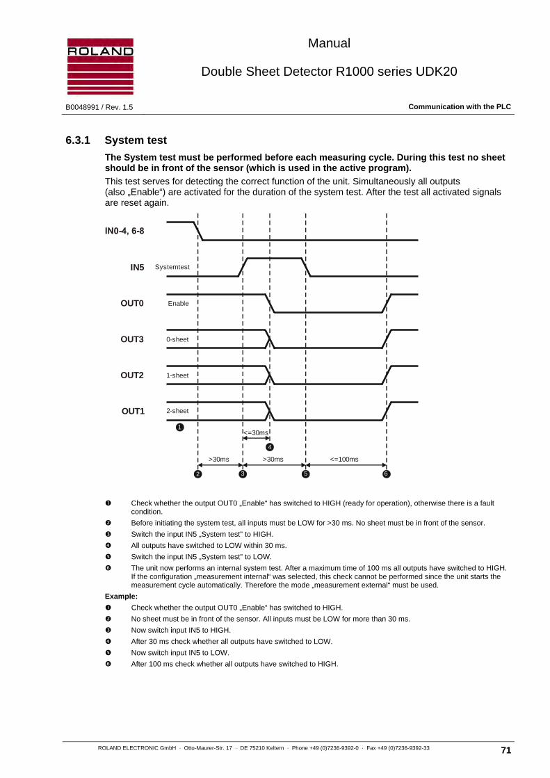
Manual
Double Sheet Detector R1000 series UDK20
B0048991 / Rev. 1.5 Communication with the PLC
ROLAND ELECTRONIC GmbH · Otto-Maurer-Str. 17 · DE 75210 Keltern · Phone +49 (0)7236-9392-0 · Fax +49 (0)7236-9392-33 71
6.3.1 System test
The System test must be performed before each measuring cycle. During this test no sheet should be in front of the sensor (which is used in the active program).
This test serves for detecting the correct function of the unit. Simultaneously all outputs (also „Enable“) are activated for the duration of the system test. After the test all activated signals are reset again.
Check whether the output OUT0 „Enable“ has switched to HIGH (ready for operation), otherwise there is a fault condition.
Before initiating the system test, all inputs must be LOW for >30 ms. No sheet must be in front of the sensor.
Switch the input IN5 „System test" to HIGH.
All outputs have switched to LOW within 30 ms.
Switch the input IN5 „System test" to LOW.
The unit now performs an internal system test. After a maximum time of 100 ms all outputs have switched to HIGH. If the configuration „measurement internal“ was selected, this check cannot be performed since the unit starts the measurement cycle automatically. Therefore the mode „measurement external“ must be used.
Example:
Check whether the output OUT0 „Enable“ has switched to HIGH.
No sheet must be in front of the sensor. All inputs must be LOW for more than 30 ms.
Now switch input IN5 to HIGH.
After 30 ms check whether all outputs have switched to LOW.
Now switch input IN5 to LOW.
After 100 ms check whether all outputs have switched to HIGH.
IN5
OUT0
OUT3
OUT2
OUT1
Systemtest
Enable
0-sheet
1-sheet
2-sheet
1
>30ms >30ms
<=30ms
<=100ms
4
2 3 5 6

Manual
Double Sheet Detector R1000 series UDK20
Communication with the PLC B0048991 / Rev. 1.5
72 ROLAND ELECTRONIC GmbH · Otto-Maurer-Str. 17 · DE 75210 Keltern · Phone +49 (0)7236-9392-0 · Fax +49 (0)7236-9392-33
6.3.2 Measurement menu selection
All 255 measuring programs can be selected via the PLC inputs.
For this the inputs IN0 to IN8 are used.
Note The inputs IN1-3 and IN5 are used also for functions other then the
selection of the measuring programs. This means that the sequence in the timing diagram has to be followed exactly.
Check whether the output OUT0 „Enable“ has switched to HIGH (ready for operation), otherwise there is a fault condition.
Before selecting a measurement program, all inputs must be LOW for 30 ms.
Switch the input IN0 „Menu selection“ to HIGH.
Simultaneously with (or delayed) switch the binary values to IN1-8.
Within 60 ms after switching IN0 "Menu selection", the outputs OUT1-3 have switched to LOW.
After the binary value has been present for a minimum of 60 ms, switch the input IN0 „Menu selection“ to LOW.
Simultaneously with (or delayed) switch back the binary value at IN1-8 (switch IN1-8 to LOW).
After a maximum time of 180 / 480 / 240 ms (depending on the material measured last and the new type of material to be measured) all outputs OUT1-3 have switched to HIGH. If the configuration „Demo mode“ was selected, measurement will start automatically again (provided a valid program has been selected). If the configuration „Measurement external“ was selected, the operation of the unit it is performed via the PLC.
OUT0
IN0
OUT1, 2, 3
Enable
IN1-8
Meas. menuSelection
Bit0-7
2-1-0-sheet
1
64
5
73
>=0ms >=0ms
2 8Complete switching time max. 270 / 570 / 330 ms(depending on the material measured and the new material to be measured)
max. 180 ms for FE to FE, NF to NF or NF to FEmax. 480 ms for FE to NF (for same sensor)max. 240 ms for FE to NF (for different sensors / SSB)
*
*
> 30ms <= 60ms
> 60ms

Manual
Double Sheet Detector R1000 series UDK20
B0048991 / Rev. 1.5 Communication with the PLC
ROLAND ELECTRONIC GmbH · Otto-Maurer-Str. 17 · DE 75210 Keltern · Phone +49 (0)7236-9392-0 · Fax +49 (0)7236-9392-33 73
Example:
Check whether the output OUT0 "Enable" has switched to HIGH.
All inputs must be LOW for more than 30 ms.
Switch input IN0 „Menu selection“ and
simultaneously the binary value to IN1-8.
Check after more than 60 ms, whether the outputs OUT1-3 have switched to LOW.
Switch the input IN0
and the binary value (IN1-8) to LOW.
Wait the necessary time (refer to the diagram) until the outputs OUT1-3 have switched back to HIGH.
Program no. Bit 7 Bit 6 Bit 5 Bit 4 Bit 3 Bit 2 Bit 1 Bit 0
1 0 0 0 0 0 0 0 0
2 0 0 0 0 0 0 0 1
… … … … … … … … …
255 1 1 1 1 1 1 1 0
not used 1 1 1 1 1 1 1 1

Manual
Double Sheet Detector R1000 series UDK20
Communication with the PLC B0048991 / Rev. 1.5
74 ROLAND ELECTRONIC GmbH · Otto-Maurer-Str. 17 · DE 75210 Keltern · Phone +49 (0)7236-9392-0 · Fax +49 (0)7236-9392-33
6.3.3 Measurement Start / Stop
External control is different for single measurement and continuous measurement. If the sequencer mode is used, the signals 0-1-2-sheet will be formed as summary output (For details refer to chapter 6.2.1).
6.3.3.1 Single measurement
The measurement result remains frozen until a new action is initiated.
*tS: The system reaction time is the time required by the unit in order to issue the result to the output after the signal "Measurement Start" has been recognized (For details refer to chapter 2.4).
Note In the relay output version the status of the outputs appears
delayed (<10 ms) due to the switching time of the relays.
Note High Level at the outputs means relay closed respectively opto
coupler low resistant. Low Level at the outputs means relay open respectively opto coupler high resistant.
Note Only for FE material (not for NF and LM): If several measurements are executed consecutively, the measuring operation time should not exceed 10 seconds. It is advisable to keep a recovery time of at least twice the measuring operation time. Example: 10 measurements within 1 second, then 2 seconds of recovering time. If the recovery time is less than twice the measuring time, the sensor will warm up and the measuring value will drift.
OUT0
IN1
Enable
1 > 30ms
2
OUT3
OUT2
IN0,2-8
Meas. Start
0-sheet
3
4
1-sheet
2-sheet
< 30ms System reaction time t *s
6
5
> 30ms
OUT1

Manual
Double Sheet Detector R1000 series UDK20
B0048991 / Rev. 1.5 Communication with the PLC
ROLAND ELECTRONIC GmbH · Otto-Maurer-Str. 17 · DE 75210 Keltern · Phone +49 (0)7236-9392-0 · Fax +49 (0)7236-9392-33 75
Check whether the output OUT0 „Enable“ has switched to HIGH (ready for operation), otherwise there is a fault condition.
Before starting a measurement, all inputs must be LOW for 30 ms.
Switch the input IN1 „Measurement Start“ to HIGH.
After 30 ms the outputs OUT 1-3 have switched to HIGH for the duration of the measurement (system reaction time, see chapters 2.2 - depending on material and thickness).
After point or 30 ms after point switch the input IN1 „Measurement Start“ to LOW.
The measurement result is available (after the system reaction time ts) at the outputs OUT1-3, it remains frozen until the new action is initiated.
Example with „fast“ PLC / BUS cycle time (< 20 ms):
Check whether the output OUT0 „Enable“ has switched to HIGH.
All inputs must be LOW for more then 30 ms.
After that switch input IN1 „Measurement Start“ to HIGH.
Check whether all outputs OUT1-3 switch to HIGH within 30 ms.
After that, switch input IN1 to LOW.
Continue to interrogate the outputs OUT1-3, until (after system reaction time ts) the measurement result is available.
Example with „slow“ PLC / BUS cycle time (> 20 ms):
Check whether the output OUT0 „Enable“ has switched to HIGH.
All inputs must be LOW for more then 30 ms.
After that, switch input IN1 „Measurement Start“ to HIGH.
After more than 30 ms switch input IN1 „Measurement Start“ to LOW.
Continue to interrogate the outputs OUT1-3, until (after system reaction time ts) the measurement result is available.

Manual
Double Sheet Detector R1000 series UDK20
Communication with the PLC B0048991 / Rev. 1.5
76 ROLAND ELECTRONIC GmbH · Otto-Maurer-Str. 17 · DE 75210 Keltern · Phone +49 (0)7236-9392-0 · Fax +49 (0)7236-9392-33
6.3.3.2 Continuous measurement
The control unit measures continuously as long as the signal “Measurement Start“ is switched to HIGH. If the signal “Measurement Start“ is switched to LOW, the measurement is aborted and the last measuring result is frozen until a new cycle is initiated.
Note In the relay output version the status of the outputs appears delayed
(<10 ms) due to the switching time of the relays.
Note High Level at the outputs means relay closed respectively opto
coupler low resistant. Low Level at the outputs means relay open respectively opto coupler high resistant.
*tS: The system reaction time is the time required by the unit in order to issue the result to the output after the signal "Measurement Start" has been recognized (For details refer to chapter 2.4).
*tp: Additional recovery time of 0.5 seconds (for FE material)
IN1
Enable
1 > 30ms
2
OUT3
OUT2
IN2-8
Meas. Start
0-sheet
3
4
1-sheet
2-sheet
< 30ms
5
> 30ms
OUT1
7
t * + s t *pt *s
6

Manual
Double Sheet Detector R1000 series UDK20
B0048991 / Rev. 1.5 Communication with the PLC
ROLAND ELECTRONIC GmbH · Otto-Maurer-Str. 17 · DE 75210 Keltern · Phone +49 (0)7236-9392-0 · Fax +49 (0)7236-9392-33 77
Check whether the output OUT0 „Enable“ has switched to HIGH (ready for operation), otherwise there is a fault condition.
Before starting measurement, all inputs must be switched to LOW for 30 ms.
Switch the input IN1 „Measurement Start“ to HIGH.
Within 30 ms, the outputs OUT 1-3 have switched to HIGH for the duration of the measurement (system reaction time, see chapter 2.2 - depending on material and thickness).
The measurement result is available after the systems reaction time ts at the outputs OUT1-3. The measurement starts again. An additional recovering time of 0.5 seconds is awaited (for FE material).
The measurement result of the 2nd measurement is available at the outputs. The measurement starts again.
Switch the input IN1 „Measurement Start“ to LOW.
The measurement is aborted, the last measurement result is now available at the outputs OUT1-3. The measurement result is frozen until a new cycle is initiated.
Example with „fast“ PLC / BUS cycle time (< 20 ms):
Check whether the output OUT0 „Enable“ has switched to HIGH.
All inputs must be LOW for more then 30 ms.
Then switch input IN1 „Measurement Start“ to HIGH.
Check whether all outputs OUT1-3 switch to HIGH within 30 ms.
Continue to interrogate the outputs OUT1-3, until (after the systems reaction time ts) the measurement result is available.
If required, interrogate several measurements.
Then switch input IN1 to LOW.
The measurement is aborted, the last measurement result is now available at the outputs OUT1-3. The measurement result is frozen until a new cycle is initiated.
Example with „slow“ PLC / BUS cycle time (> 20 ms):
Check whether the output OUT0 „Enable“ has switched to HIGH.
All inputs must be LOW for more then 30 ms.
Then switch input IN1 „Measurement Start“ to HIGH.
Continue to interrogate the outputs OUT1-3 until (after the systems reaction time ts) the measurement result is available.
If required interrogate several measurements.
Then switch input IN1 to LOW.
The measurement is aborted, the last measurement result is now available at the outputs OUT1-3. The measurement result is frozen until a new cycle is initiated.

Manual
Double Sheet Detector R1000 series UDK20
Communication with the PLC B0048991 / Rev. 1.5
78 ROLAND ELECTRONIC GmbH · Otto-Maurer-Str. 17 · DE 75210 Keltern · Phone +49 (0)7236-9392-0 · Fax +49 (0)7236-9392-33
6.3.4 External zero adjust (via PLC inputs)
This function may be required for special applications. It is, however, switched off in the standard factory adjustment. If required it can be activated according chapter “7. Start-up“. The sensors used in the active program are nulled.
Note During Zero adjust no sheet must be in front of the sensor.
Check whether the output OUT0 „Enable“ has switched to HIGH (ready for operation), otherwise there is a fault condition.
Before initiating zero adjust all inputs must be LOW for 30 ms. No sheet must be in front of the sensor.
Switch the input IN3 „Zero adjust“ to HIGH.
Within 30 ms the outputs OUT1-3 have switched to LOW.
After point or 30 ms after point switch the input IN3 „Zero adjust“ to LOW.
Now the unit performs a zero adjust. The zero adjust is completed within 15s and the outputs OUT1-3 switch to HIGH.
Example:
Check whether the output OUT0 „Enable“ has switched to HIGH.
No sheet must be in front of the sensor. All inputs must be LOW for more than 30 ms.
Now switch input IN3 to HIGH.
After 30 ms check whether outputs 1-3 have switched to LOW.
Now switch input IN3 to LOW.
After >15 seconds check whether the outputs 1-3 have switched to HIGH.
IN0-2, 4-10
Enable
1 > 30ms
2
OUT3
OUT2
IN3Zero adjust
3
4
< 30ms
5
> 30ms
OUT1
6
0-sheet
1-sheet
2-sheet
1 sensor: 8 s; 2 sensors 15 s

Manual
Double Sheet Detector R1000 series UDK20
B0048991 / Rev. 1.5 Communication with the PLC
ROLAND ELECTRONIC GmbH · Otto-Maurer-Str. 17 · DE 75210 Keltern · Phone +49 (0)7236-9392-0 · Fax +49 (0)7236-9392-33 79
6.3.5 External Teach-In (via PLC inputs)
This function may be required for special applications. It is, however, switched off in the standard factory adjustment. If required it can be activated according chapter 7 “ Start-up“. The sensors used in the active program are teached.
Note During Teach-In one sheet of nominal thickness must be placed in front of the sensor.
Note A zero adjust procedure must be executed immediately before the Teach-In procedure.
Check whether the output OUT0 „Enable“ has switched to HIGH (ready for operation), otherwise there is a fault condition.
Before initiating the Teach-In, all inputs must be LOW for 30 ms. One sheet of nominal thickness must be placed in front of the sensor.
Switch the input IN2 „Teach-In“ to HIGH.
Within 30 ms the outputs OUT1-3 have switched to LOW.
After point or 30 ms after point switch the input IN2 „Teach-In“ to LOW.
Now the unit performs a „Teach-In“ procedure, which is completed within 7s. Then the outputs OUT1-3 switch to HIGH.
Example:
Check whether the output OUT0 „Enable“ has switched to HIGH.
One sheet must be in front of the sensor. All inputs must be LOW for more than 30 ms.
Switch input IN2 to HIGH.
After 30 ms check whether outputs 1-3 have switched to LOW.
Switch input IN2 „Teach-In“ to LOW.
After < 7 seconds check whether the outputs OUT1-3 have switched to HIGH.
Enable
1> 30ms
2
OUT3
OUT2
Teach-In
3
4
< 30ms
5
> 30ms
OUT1
6
< 7 sec.
0-sheet
1-sheet
2-sheet
IN0-1, 3-8
IN2

Manual
Double Sheet Detector R1000 series UDK20
Start-up B0048991 / Rev. 1.5
80 ROLAND ELECTRONIC GmbH · Otto-Maurer-Str. 17 · DE 75210 Keltern · Phone +49 (0)7236-9392-0 · Fax +49 (0)7236-9392-33
6.3.6 Typical measurement cycle for unit in destacking application
In order to warrant reliable functioning of the system the following operating cycle is recommended.
It is recommended to perform step 2 at each cycle.
1. Selection of the desired measuring program.
2. System test (This test must be performed). See timing diagram chapter “6.3.1 System test“
3. The sensor is lowered onto the stack (this stack contains 1 or more sheets).
4. Measurement in order to detect last sheet in the stack (1-sheet signal = only one sheet in the stack) provided there is no other metal under the stack.
5. Destack a sheet and move into monitoring position - at least 2 cm (.8 inch) away from stack.
6. Monitor and initiate action depending on measurement result:
• 0-sheet: Repeat destacking operation. • 2-sheet: Initiate actions to remove double sheet or several sheets from destacker.
After the measure again.
Attention: During the removal operation measurement should be switched off because of potentially undefined conditions, air gaps between sensor and sheet etc.
• 1-sheet: continue with point 7.
7. Transport sheet into the proper loading position.
8. Measurement to verify that the sensor is still on the sheet.
9. Release the sheet.
10. After de-stacking a sheet perform security check - Is the sheet de-stacked ?
11. Before de-stacking a new sheet perform point 1 “Selection of the desired measuring program“ or point 2 “System test“.
6.4 Internal control (Demo mode)
In this operating mode the system continuously executes measurements and activates OUT0 … OUT3.
In general, this operating mode is suitable for demonstration purposes only.
Prerequisite:
• Supply voltage applied
• System parameter 4 set to demo mode
• Teach-In has been executed
The refresh rate of the measurement is:
• for FE-Material 1 second
• for NF and LM < 0,085 seconds

Manual
Double Sheet Detector R1000 series UDK20
B0048991 / Rev. 1.5 Start-up
ROLAND ELECTRONIC GmbH · Otto-Maurer-Str. 17 · DE 75210 Keltern · Phone +49 (0)7236-9392-0 · Fax +49 (0)7236-9392-33 81
7 Start-up
7.1 Initially applying power to the system
The R1000 UDK20 is designed for an operating voltage of 24 VDC (+ 6 V / - 2 V). This voltage is to be checked before applying power. The control unit is automatically switched on by applying the power. After applying power, the type of system, the version number and the bus system message are briefly displayed. Then the system switches into that measurement menu, which was active before the unit was switched off.
7.2 Operation
Note The system is factory adjusted for “single measurement“. Therefore the system functions only if the signal “measurement start“ is activated. The modification of the configuration is described in the following sections.
After applying power to the system, the system type and the version number are briefly displayed. Afterwards the system switches into that measurement menu which was active before the unit was switched off.
1 LED functions 2 Pushbutton functions 3 Program number 4 Selected sensor 5 Type of material 6 Nominal thickness 7 Measurement status 8 Lower limit value 9 Sensor number with measured value 10 Upper limit value
Fig. 28: Frontal view of the R1000 with enlarged display detail
LED functions (symbols above the keys)
< ON, if the measured value reaches (or falls short of) the lower limit value.
Norm ON, if the measured value is within the lower and upper limit values.
> ON, if the measured value reaches (or exceeds) the upper limit value.
Enable - blinks, if a fault is present - ON, if the equipment is in measurement mode - OFF, during parameter programming with the keyboard
Key functions (symbols below the keys)
▲ Changes the parameters (forward)
▼ Changes the parameters (backwards)
Enter Selects a parameter for changing and confirming the change
Menu Activates the menu level, for deleting a fault message and exiting the menu level.

Manual
Double Sheet Detector R1000 series UDK20
Start-up B0048991 / Rev. 1.5
82 ROLAND ELECTRONIC GmbH · Otto-Maurer-Str. 17 · DE 75210 Keltern · Phone +49 (0)7236-9392-0 · Fax +49 (0)7236-9392-33
7.3 Configuration menu
7.3.1 Main menu structure
Fig. 29: Main structure of configuration menu
7.3.2 Sub structure “Program parameter”
Fig. 30: Sub structure „Program parameter“
MENU
Config.
Review change(password)
System Parameter 7.7 General system configuration
Program Parameter 7.6 Parameter of the respective measurement programs
Data backup 7.8 Backup of the data stored in the systemvia RS232-Interface
AutoNFFELM (slightly magn. NF)
offall
missingonwithout
ok
separate
Material
Program Parameter
Program no. (1-255)
Sensor number
Nominal thickness 0.03 - 4 mm (0.001 - 0.157 inch)
up% (100-150%) and absolute
low% (0 - 99%) and absolute
Zero adjust
Teach-In

Manual
Double Sheet Detector R1000 series UDK20
B0048991 / Rev. 1.5 Start-up
ROLAND ELECTRONIC GmbH · Otto-Maurer-Str. 17 · DE 75210 Keltern · Phone +49 (0)7236-9392-0 · Fax +49 (0)7236-9392-33 83
7.3.3 Sub structure “System parameter”
Fig. 31: Sub structure „System parameter“
Single measurement (external)Continuous measurement (external)
offon
yesno
(Factory setting, do not change!)
fast
System parameter
mm / inch
PW42A
Demo mode
66 / 125 %
0 V active24 V active
conductivity
conductivity range
1 / 2 / 3 / 4 (at SSB 1-4; at 2PW 1 / 2)
normal
(Clear Program Parameter)
Version
HW-V: UDK20-XX-XXXSW-V: XXX
FE-T-Limit33 / 142 %
nominal valueteach faktor
thickness rangethickness with AD valuefrequency + gain
FE-Measurement
Language
Sensor type
Number of sensors
Dimension
Measuring mode
CLR Parameter
Password
external adjust
Output level 0-1-2-sheet
W-Diagnosis
Diagnosis factor
yesno

Manual
Double Sheet Detector R1000 series UDK20
Start-up B0048991 / Rev. 1.5
84 ROLAND ELECTRONIC GmbH · Otto-Maurer-Str. 17 · DE 75210 Keltern · Phone +49 (0)7236-9392-0 · Fax +49 (0)7236-9392-33
7.4 General information regarding the configuration
Note The correct configuration depends on the communication with the PLC,
on the measurement task and the connected components.
The following rules apply to the operation in the configuration mode:
• The configuration mode is activated (while in measurement mode) by pressing the MENU key.
• The configuration mode is terminated or cancelled by pressing the MENU key.
• The selected / set parameters can be changed when the items are blinking in the display.
• The selected / set parameters are activated by pressing the ENTER key.
7.5 Changing, setting-up or checking the configuration
In order to select, set-up or check the system / program parameters, press the MENU key.
The following menu is shown.
Fig. 32: Indication after calling-up the menu
This menu option permits either reviewing or changing the configuration.
Configuration review: The system / program parameters cannot be changed. The measurement mode is not interrupted.
Configuration change: All system / program parameters can be changed after entering the password.
The following menu option is shown.
Fig. 33: Password request
Each blinking digit can be changed with the arrow keys and confirmed with ENTER. After having entered the correct password, the following menu appears for the adjustment of the configuration mode.
If the entered password is incorrect then the cursor returns to the first digit of the password and the input must be repeated. The input of the password can be aborted by pressing the MENU button.
Note: A fault is generated if PLC commands are executed while entering the
password or changing parameters.
configuration review
password 4711

Manual
Double Sheet Detector R1000 series UDK20
B0048991 / Rev. 1.5 Start-up
ROLAND ELECTRONIC GmbH · Otto-Maurer-Str. 17 · DE 75210 Keltern · Phone +49 (0)7236-9392-0 · Fax +49 (0)7236-9392-33 85
Fig. 34: Selecting the configuration mode
Available configuration modes:
• Configuration system parameter
• Configuration program parameter
• Data backup
System parameters are general adjustments (e.g. language). Program parameters are application specific adjustments (e.g. input of nominal sheet thickness).
Note After exiting the configuration mode the password remains active for five
minutes. Thus other configuration adjustments can be made, without re-entering the password. If no key is pressed (while in the menu level), then the program changes to the measurement mode
7.6 Program parameters
The program parameters contain the information required for the various measurement programs. For accessing the program parameters, select the mode “configuration program parameter“ and confirm with ENTER.
Program parameter 1: Selecting the measuring program to be configured.
Fig. 35: Selecting the program to be configured
Here the measuring program (1-255) to be configured is selected. All following adjustments apply to the selected program (here: program no. 1).
Program parameter 2: Selecting the sensor to be used for measurement.
Fig. 36: Selecting the sensor
Possible choices:
• 2PW-units: 1 / 2 / 1+2
• with SSB: 1 / 2 / 3 / 4
program par. 1 program no.: 1
program par. 2 sensor: 1
configuration program param.

Manual
Double Sheet Detector R1000 series UDK20
Start-up B0048991 / Rev. 1.5
86 ROLAND ELECTRONIC GmbH · Otto-Maurer-Str. 17 · DE 75210 Keltern · Phone +49 (0)7236-9392-0 · Fax +49 (0)7236-9392-33
Program parameter 3: Setting the material of the sheet to be measured.
Fig. 37: Setting the material
Possible choices:
• Auto: During Teach-In the system determines by itself the type of material in front of the sensor.
• NF (non-ferrous): Non magnetic material, e.g. aluminium, austenitic stainless steel
• FE (ferrous): Magnetic material
• mag. NF (LM): low magnetic material
Program parameter 4: Setting the nominal thickness of the sheet to be measured.
Fig. 38: Setting the nominal thickness
Value range:
• 0.03 mm to 4 mm (.001 inch to 0.157 inch)
Program parameter 5: Setting the percentage threshold of the upper limit value.
Fig. 39: Setting the upper limit
Value range:
• 100% to 150%
At the same time the absolute limit value is displayed.
Program parameter 6: Setting the percentage threshold of the lower limit value.
Fig. 40: Setting the lower limit
Value range:
• 0% to 99%
At the same time the absolute limit value is displayed.
program par. 3 material: auto
program par. 4 nominal: 0.90mm
program par. 5 up 150% 1.350mm
program par. 6 low: 50% 0.450mm

Manual
Double Sheet Detector R1000 series UDK20
B0048991 / Rev. 1.5 Start-up
ROLAND ELECTRONIC GmbH · Otto-Maurer-Str. 17 · DE 75210 Keltern · Phone +49 (0)7236-9392-0 · Fax +49 (0)7236-9392-33 87
Program parameter 7: Zero adjust
Fig. 41: Status of Zero adjust
Zero adjust is initiated with the ENTER key. If no zero adjust was executed or if it has to be repeated, the menu option “on“ has to be selected.
Then the following message appears (with version 2PW only):
• Separate: All connected sensors must be zero adjusted individually, each sensor is addressed individually for yes or no.
• Common: All sensors are zero adjusted at the same time. In any case the zero adjust continues with the following message, requesting to remove the sheet:
Fig. 42: Removing sheet for zero adjust
After having the sheet removed, press the ENTER key. Then the following message appears during the zero adjust:
Fig. 43: Display during zero adjust
Note Fault messages are described in the chapter 9. “Fault messages“.
When the zero adjust is completed, the following message appears:
Fig. 44: Zero adjust successfully completed
The zero adjust is now completed.
program par. 7 zero adj.: off
program par. 7 remove sheet!
program par. 7 please wait
program par. 7 zero adj.: done

Manual
Double Sheet Detector R1000 series UDK20
Start-up B0048991 / Rev. 1.5
88 ROLAND ELECTRONIC GmbH · Otto-Maurer-Str. 17 · DE 75210 Keltern · Phone +49 (0)7236-9392-0 · Fax +49 (0)7236-9392-33
Program parameter 8: Teach-In
Fig. 45: Status of Teach-In
Possible choices:
• Missing: A Teach-In has not been executed (only for NF) • Without: There is no Teach-In existing, unit can be operated anyhow (only for FE) • OK: A Teach-In was already executed • On: Performs a Teach-In
Note In order to enable measuring with a particular parameter set, a Teach-In must have been executed.
If no Teach-In was executed or if a Teach-In has to be repeated, the menu option “on“ has to be selected. Then the following two messages appears in succession:
Fig. 46: Removing sheet for Teach-In
Fig. 47: Attaching a sheet for Teach-In
Now a sheet with the nominal thickness must be presented to the sensor.
Attention A sheet must be attached to the sensor without air gap. The position of the sheet during Teach-In must be the same as for normal operation. Otherwise the measurement result could be faulty.
Then press the ENTER key.
During the Teach-In procedure the following message is displayed:
Fig. 48: Display during the Teach-In
Note Fault messages are described in chapter 9. “Fault messages ".
program par. 8 Teach-In: on
program par. 8 remove sheet!
program par. 8 attach sheet!
program par. 8 please wait
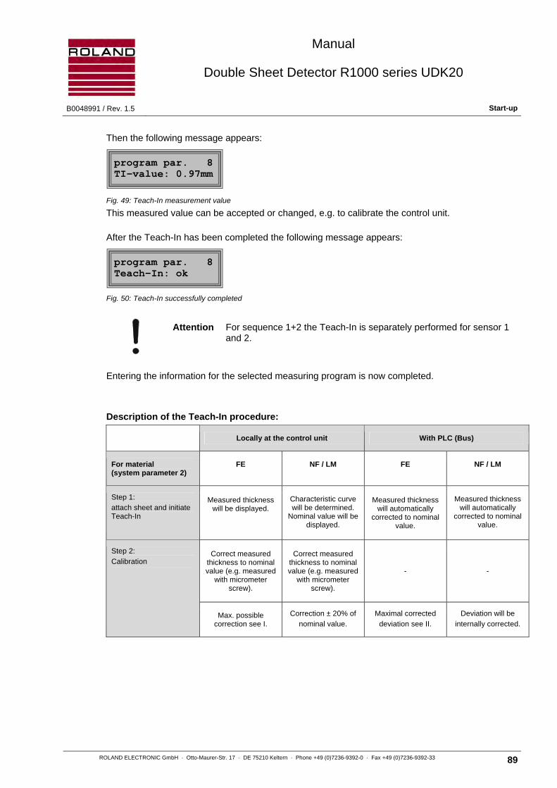
Manual
Double Sheet Detector R1000 series UDK20
B0048991 / Rev. 1.5 Start-up
ROLAND ELECTRONIC GmbH · Otto-Maurer-Str. 17 · DE 75210 Keltern · Phone +49 (0)7236-9392-0 · Fax +49 (0)7236-9392-33 89
Then the following message appears:
Fig. 49: Teach-In measurement value
This measured value can be accepted or changed, e.g. to calibrate the control unit.
After the Teach-In has been completed the following message appears:
Fig. 50: Teach-In successfully completed
Attention For sequence 1+2 the Teach-In is separately performed for sensor 1 and 2.
Entering the information for the selected measuring program is now completed.
Description of the Teach-In procedure:
Locally at the control unit With PLC (Bus)
For material (system parameter 2)
FE NF / LM FE NF / LM
Step 1:
attach sheet and initiate Teach-In
Measured thickness will be displayed.
Characteristic curve will be determined.
Nominal value will be displayed.
Measured thickness will automatically
corrected to nominal value.
Measured thickness will automatically
corrected to nominal value.
Step 2:
Calibration Correct measured
thickness to nominal value (e.g. measured
with micrometer screw).
Correct measured thickness to nominal value (e.g. measured
with micrometer screw).
- -
Max. possible correction see I.
Correction ± 20% of
nominal value.
Maximal corrected
deviation see II.
Deviation will be
internally corrected.
program par. 8 TI-value: 0.97mm
program par. 8 Teach-In: ok

Manual
Double Sheet Detector R1000 series UDK20
Start-up B0048991 / Rev. 1.5
90 ROLAND ELECTRONIC GmbH · Otto-Maurer-Str. 17 · DE 75210 Keltern · Phone +49 (0)7236-9392-0 · Fax +49 (0)7236-9392-33
I. depending on the set T-limit (system parameter)
a: 66% / 125%:
• possible upward correction of the displayed thickness:
max. 150 % of the indicated value but not more than 125 % of the set nominal thickness, but not more than the max. measurable thickness (depending on sensor; 4mm for PW42AGS)
• possible downward correction of the displayed thickness:
min. 80% of the indicated value but not less than 66 % of the set nominal thickness
b: 33% / 142%:
• possible upward correction of the displayed thickness:
max. 300 % of the indicated value but not more than 142 % of the set nominal thickness, but not more than the max. measurable thickness (depending on sensor; 4mm for PW42AGS)
• possible downward correction of the displayed thickness:
min. 70% of the indicated value but not less than 33 % of the set nominal thickness
II. depending on the set T-limit (system parameter)
a: 66% / 125%:
The ratio of measured to nominal value must be between 66% and 125%
b: 33% / 142%:
The ratio of measured to nominal value must be between 33% and 142%
Attention For operation with „sequence 1+2“ the values for sensor 1 and 2 may not deviate from each other for more than ± 20 %.

Manual
Double Sheet Detector R1000 series UDK20
B0048991 / Rev. 1.5 Start-up
ROLAND ELECTRONIC GmbH · Otto-Maurer-Str. 17 · DE 75210 Keltern · Phone +49 (0)7236-9392-0 · Fax +49 (0)7236-9392-33 91
7.7 System parameters
Note The selected system configuration should be documented in the form
“System configuration“ in the chapter 13.2. This information is required in case a system needs to be exchanged.
The general adjustments are specified in the system parameters. For accessing, select the “system parameter configuration“ mode and confirm with ENTER.
System parameter 1: Setting the dialogue language.
Fig. 51: Selecting the dialogue language
System parameter 2: Specifying the type of sensor.
Fig. 52: Specifying the type of sensor
Currently only the type of sensor PW42A is selectable.
System parameter 3: Specifying the number of connected sensors.
Fig. 53: Specifying the number of sensors
Possible choices:
• for 2PW-unit: 1 / 2 sensors • for SSB: 1 / 2 / 3 / 4 sensors
Attention If a particular configuration is changed, all stored program parameters are deleted. Then for all types of material the nominal thicknesses must be entered again and the Teach-In executed.
system param. 1 language:english
system param. 2 sensor type:PW42
system param. 3 number sensors:2

Manual
Double Sheet Detector R1000 series UDK20
Start-up B0048991 / Rev. 1.5
92 ROLAND ELECTRONIC GmbH · Otto-Maurer-Str. 17 · DE 75210 Keltern · Phone +49 (0)7236-9392-0 · Fax +49 (0)7236-9392-33
System parameter 4: Selecting the dimensions for the display (mm / inch).
If the measurement dimensions are changed, then the sheet metal thicknesses of the stored programs parameter are converted into the new dimension.
Fig. 54: Selecting the dimension for the display
System parameter 5: Adjusting the measuring mode.
Fig. 55: Adjusting the measuring mode
Possible measurement modes:
• External continuous measurement: The system executes measurements, as long as the “Measurement start“ signal is applied via the external PLC input. For FE material the repetition time of the measurement is 0.5 seconds; for NF and LM it is less than 0.085 seconds.
• External single measuring: The system measures once if the “Measurement start“ signal is applied via the external PLC input. Each measurement must initiated separately. The hints in chapter 6.1.3.1 „timing diagram single measurement“ must be abided by.
• Demo mode: This mode of operation is intended for equipment demonstrations but not for the normal process operation. The system executes measurements continuously. For FE material the repetition time of the measurement is 1 second; for NF and LM it is less than 0.085 seconds.
System parameter 6: Selecting the speed of measurement.
Fig. 56: Selecting the speed of measurement
Possible choices:
• FE Measurement normal: With this kind of measuring the system reaction time depends on the measured sheet thickness. The maximum can be inferred from the diagrams in the chapter 2.2 "Sensor data“.
• FE Measurement fast: Here the system can detect whether double sheet metal is in front of the sensor before the "normal" end of the measurement. The system reaction time is shorter, depending on the adjusted nominal thickness as well as the upper limit value. Disadvantage: In case of measuring results larger than the double sheet threshold, a double sheet.
For NF and LM (slightly magnetic NF) the exact measuring value is always output.
system param. 4 Dimension: mm
system param. 5 mode: ext.contin
system param. 6 measure: fast

Manual
Double Sheet Detector R1000 series UDK20
B0048991 / Rev. 1.5 Start-up
ROLAND ELECTRONIC GmbH · Otto-Maurer-Str. 17 · DE 75210 Keltern · Phone +49 (0)7236-9392-0 · Fax +49 (0)7236-9392-33 93
System parameter 7: Specifying the Teach-In limits for FE.
Fig. 57: Setting Teach-In limit
Possible choices:
• 66% / 125 % (default setting)
• 33% / 142 %
During Teach-In of FE material the deviation of the measured thickness from the nominal thickness is monitored. Certain ferro-magnetic materials show a larger deviation than usual. In those cases the 33%/142% setting instead of the default 66%/125% setting is useful. Both values represent the permitted relative range from measured to nominal thickness. If the measuring value is not within this range, the Teach-In cannot be performed and will be aborted with an error message.
System parameter 8: Deleting all measuring programs.
Fig. 58: Deleting of measuring programs
Attention The deletion cannot be undone.
System parameter 9: Switching the password function on / off.
Fig. 59: Switching the password on / off
Attention If no password is activated, then all parameters can be accessed at any time. We recommend this only during starting-up the system. For daily operation the password function should be activated.
System parameter 10: Deactivating / activating the external calibration
Fig. 60: Deactivating / activating the external calibration
Here the external calibration can be deactivated, which is possible via the interface with the signals “Teach-In 0-sheet“ and “Teach-In 1-sheet“.
system param. 7 T-limit:66%/125%
system param. 8 CLR param.: no
system param. 9 password: yes
system param. 10 ext. adj.: no

Manual
Double Sheet Detector R1000 series UDK20
Start-up B0048991 / Rev. 1.5
94 ROLAND ELECTRONIC GmbH · Otto-Maurer-Str. 17 · DE 75210 Keltern · Phone +49 (0)7236-9392-0 · Fax +49 (0)7236-9392-33
System parameter 11: Setting the output logic (0-sheet, 1-sheet, 2-sheet outputs).
Fig. 61: Setting the output logic
Possible choices:
• 0 V: As shown in the timing diagrams and the wiring diagrams
• +24 V: The outputs 0-sheet, 1-sheet and 2-sheet are inverted, i.e. the respective signals in the timing diagrams and wiring diagrams must be seen inverted.
Note The output “Enable“ is not affected thereby.
System parameter 12: Equipment diagnostics (Teach-In factors).
Fig. 62: Diagnostics factor
The ENTER key leads to the following menu item:
Fig. 63: Indicating the investigated conductance
Here the conductivity investigated for this program is shown (here: prog. 12)
• Extra: = slightly magnetical NF material
• FE = magnetical steel
For NF material the conductivity range is shown.
With the ENTER key and UP/ DOWN keys all programs can be polled / indicated. The ENTER key will exit the section.
The UP key leads to the following menu item:
Fig. 64: Indicating the nominal thickness for the program
Here the nominal thickness for this program is shown (here: prog. 12).
With the ENTER key and UP/ DOWN keys all programs can be polled / indicated. The ENTER key will exit the section.
system param. 11 output 0-1-2: 0V
system param. 12 diagnost. factor
system param. 12 P12 EC:24-32ms/m
system param. 12 P12 N=2.12mm

Manual
Double Sheet Detector R1000 series UDK20
B0048991 / Rev. 1.5 Start-up
ROLAND ELECTRONIC GmbH · Otto-Maurer-Str. 17 · DE 75210 Keltern · Phone +49 (0)7236-9392-0 · Fax +49 (0)7236-9392-33 95
The UP key leads to the following menu item:
Fig. 65: Indicating the factor for the program, investigated on Teach-In
Here the factor (2PW units: both factors) for this program, investigated on Teach-In, is shown (here: prog. 12).
With the ENTER key and UP/ DOWN keys all programs can be polled / indicated. The ENTER key will exit the section.
The UP key leads to the following menu item:
Fig. 66: Exiting the factor diagnosis section
The ENTER key will exit the factor diagnostics.
System parameter 13: Equipment diagnostics (W-diagnosis)
Fig. 67: W-diagnostics
Note The settings of the current program will be taken over as default settings.
The ENTER key leads to the following menu item:
Fig. 68: Setting the conductivity range fort he diagnosis
Here the conductivity range for the diagnosis is set.
• Extra: = slightly magnetical NF material
• FE = magnetical steel
For NF material the conductivity range is shown.
With the ENTER key and UP/ DOWN keys all ranges can be selected. The ENTER key will exit the section.
system param. 12 P12 FKT=1.112
system param. 12 P12 EXIT
system param. 13 W-diagnostics
system param. 13 EC: 24-32mS/m

Manual
Double Sheet Detector R1000 series UDK20
Start-up B0048991 / Rev. 1.5
96 ROLAND ELECTRONIC GmbH · Otto-Maurer-Str. 17 · DE 75210 Keltern · Phone +49 (0)7236-9392-0 · Fax +49 (0)7236-9392-33
The UP key leads to the following menu item:
Fig. 69: Setting the thickness range for the diagnosis
Here the thickness range for the diagnosis is set. With the ENTER key and UP/ DOWN keys all ranges can be selected. The ENTER key will exit the section.
The UP key leads to the following menu item:
Fig. 70: Indicating the thickness calculated from the characteristic curve
Here the value of the analog-digital converter and the thickness (calculated from the characteristic curve) are shown (without Teach-In correction). For 2PW units the values for both sensors will be shown.
The UP key leads to the following menu item:
Fig. 71: Indicating the frequency and gain
Here the used frequency and gain is shown.
The UP key leads to the following menu item:
Fig. 72: De-magnetizing the sensor
Here the sensor will be de-magnetized.
The UP key leads to the following menu item:
Fig. 73: Exiting the factor diagnosis section
The ENTER key will exit the factor diagnosis section.
system param. 13 DB: <4.00 mm
system param. 13 AD:2048 D:1.22mm
system param. 13 F=250Hz V=157
system param. 13 sensor demagnet.
system param. 13 EXIT

Manual
Double Sheet Detector R1000 series UDK20
B0048991 / Rev. 1.5 Start-up
ROLAND ELECTRONIC GmbH · Otto-Maurer-Str. 17 · DE 75210 Keltern · Phone +49 (0)7236-9392-0 · Fax +49 (0)7236-9392-33 97
System parameter: Indication of Type of unit, Software and Hardware
Fig.. 74: Indication of Type of unit, Software and Hardware
Code:
UDK20 Type of unit (2) 2 sensors connected
2PW Version with 2 sensors SW Software version
B Version B HW Hardware version
O Version Opto coupler
System parameter 14: Indication of system version.
Fig. 75: Indication of the system version
This factory setting must not be changed!
7.8 Data backup via serial RS232-interface (only for C-versions)
For better prevention against data loss, a data backup procedure is available for the system configuration and the parameter sets. This is performed via the RS232-interface (only for C- versions). The secured data can be tranfered to spare units in case of exchange after a failure.
The data backup is accomplished with the RPP-XP software available from ROLAND (for WinXP).
The procedure can be selected in the menu configuration. The following menu is displayed during the data backup.
Fig. 76: Status of data backup
UDK20-2PW-B-0(2) SW:01 HW:01
system param. 14 VERSION: BO
ParameterBack-Up active
Manual
Double Sheet Detector R1000 series UDK20
Operation B0048991 / Rev. 1.5
98 ROLAND ELECTRONIC GmbH · Otto-Maurer-Str. 17 · DE 75210 Keltern · Phone +49 (0)7236-9392-0 · Fax +49 (0)7236-9392-33
Blank Page

Manual
Double Sheet Detector R1000 series UDK20
B0048991 / Rev. 1.5 Operation
ROLAND ELECTRONIC GmbH · Otto-Maurer-Str. 17 · DE 75210 Keltern · Phone +49 (0)7236-9392-0 · Fax +49 (0)7236-9392-33 99
8 Operation
8.1 Abbreviated operating instructions
After applying power to the system, the system type and the version number are briefly displayed. Afterwards the system switches into that measurement menu which was active before the unit was switched off.
Note The system is factory adjusted for “single measurement“. Therefore the system functions only if the signal “measurement start“ is activated. The modification of the configuration is described in the following sections.
1 LED functions 2 Pushbutton functions 3 Program number 4 Selected sensor 5 Type of material 6 Nominal thickness 7 Measurement status 8 Lower limit value 9 Sensor number with measured value 10 Upper limit value
Fig. 77: Frontal view of the R1000 with enlarged display detail
LED functions (symbols above the keys)
< ON, if the measured value reaches (or falls short of) the lower limit value.
Norm ON, if the measured value is within the lower and upper limit values.
> ON, if the measured value reaches (or exceeds) the upper limit value.
Enable - blinks, if a fault is present - ON, if the equipment is in measurement mode - OFF, during parameter programming with the keyboard
Key functions (symbols below the keys)
▲ Changes the parameters (forward)
▼ Changes the parameters (backwards)
Enter Selects a parameter for changing and confirming the change
Menu Activates the menu level, for deleting a fault message and exiting the menu level.

Manual
Double Sheet Detector R1000 series UDK20
Operation B0048991 / Rev. 1.5
100 ROLAND ELECTRONIC GmbH · Otto-Maurer-Str. 17 · DE 75210 Keltern · Phone +49 (0)7236-9392-0 · Fax +49 (0)7236-9392-33
In the measuring mode, the measured value is shown on the display. The comparison of the measured value with the adjusted thresholds is done automatically by the control unit. The result is transmitted via the interface to the PLC and also to the front panel LED's.
During the normal measurement process no further actions on the control units are necessary with the following few exceptions.
The following situations require action directly at the control unit:
• Clear fault and error messages (see to chapter 9. “Fault messages, causes and remedies“)
• Teaching of new types of metal and sheet metal thicknesses (see section 7.6 “Configuration of program parameters“)
• Clearing a 2-sheet condition (in preparation)
The following notes for measuring operations should be observed:
Note If the measured value fluctuates and deviates substantially from nominal value during normal operation then an air gap between sensor and sheet surface is the most likely cause. A renewed Teach-In cannot solve this problem.
Note With non-ferrous materials (e.g. aluminum) changes in the electrical conductivity can occur requiring a Teach-In.
Note Do not adjust the upper limit (“up“) above 120 %.

Manual
Double Sheet Detector R1000 series UDK20
B0048991 / Rev. 1.5 Operation
ROLAND ELECTRONIC GmbH · Otto-Maurer-Str. 17 · DE 75210 Keltern · Phone +49 (0)7236-9392-0 · Fax +49 (0)7236-9392-33 101
8.2 Entering a measurement program
1 Make sure that there is no sheet in front of the sensor
2 Press them menu key and move to “change“, confirm with ENTER key
3 Enter the password
4 Move to "program parameter" and confirm with ENTER key
5 Make sure that there is no sheet in front of the sensor
6 Select the desired program number in the control unit
7 If sensor a Sensor Switch Box is installed select the desired sensor
8 For the type of material select “auto“
9 Enter nominal thickness (standard thickness of the sheet to be processed)
10 Set lower threshold TU to 80% set (default settings)
11 Set upper threshold TO to 120% set (default settings)
12 Ensure that no sheet is in front of the sensor
13 Select "Teach-In" and move to “on“, confirm with ENTER key
14 Remove sheet in front of the sensor, confirm with ENTER key
15 If the control unit signals “attach sheet to sensor“, operate machinery to accomplish this. Ensure that there is no air gap between sensor and sheet metal surface. Confirm with ENTER key.
Attention The sheet used for the teaching process must have the same sheet thickness and same electrical conductivity (in case of non- magnetic metal e.g. aluminum) as the sheet to be processed.
16 The control unit shows the measured thickness in the display.
General rules for monitoring ferrous material (steel that can be magnetized) and non-ferrous materials (aluminum, non-magnetic stainless steel, slightly magnetic non-ferrous material):
• FE: The measured value should not deviate by more then 5%, (max. 10% with coated sheets, exceeding 10% with nickel) from the actual thickness of the measured sheet. If it deviates more, then the cause could be a wrong sheet thickness or an air gap, which has to be eliminated (do not use bowed sheet for teaching). The measured value must now be adjusted to the actual sheet thickness.
• NF and LM (slightly magnetic material): The measured value must be adjusted to the actual sheet thickness
17 Confirm the Teach-In and adjustment with the ENTER key and exit the menu “programming“.
Example: Nominal thickness 2.00 mm
The micrometer measures actual value to be: 1.92 mm.
The Teach-In shows a value of: 1.89 mm.
The display value must now be corrected to 1.92 mm.

Manual
Double Sheet Detector R1000 series UDK20
Fault messages, causes and remedies B0048991 / Rev. 1.5
102 ROLAND ELECTRONIC GmbH · Otto-Maurer-Str. 17 · DE 75210 Keltern · Phone +49 (0)7236-9392-0 · Fax +49 (0)7236-9392-33
Blank page

Manual
Double Sheet Detector R1000 series UDK20
B0048991 / Rev. 1.5 Fault messages, causes and remedies
ROLAND ELECTRONIC GmbH · Otto-Maurer-Str. 17 · DE 75210 Keltern · Phone +49 (0)7236-9392-0 · Fax +49 (0)7236-9392-33 103
9 Fault messages, causes and remedies
In case of malfunction a message containing the fault number and the associated error text is displayed
Fig. 78: Example of a fault message
The fault number indicates the fault and the probable cause. The fault description and the suitable measures to remedy the fault condition are found in the following tables. The cause of malfunction must be eliminated before the equipment can continue operation.
The fault can be cleared by pressing the MENU key on the control unit.
Note As long as the cause of the fault is not eliminated, the fault cannot be
cleared.
The fault messages are summarized into the following classes:
• Memory faults
• Zero adjust faults
• Teach-In faults
• Transmission faults (RS232)
• Measuring operating faults
• Keyboard faults
• Operating voltage faults
• Sensor-Switch-Box faults
• PLC input faults
• Other faults
9.1 Fault messages of the Sensor-Switch-Box
If the Sensor-Switch-Box was configured though none is attached to the system, then the system emits a fault message. In order to reconfigure the equipment to the correct adjustment “no Sensor Switch Box“, the unit must be switched off and on.
The following message is displayed:
Fig. 79: System does not recognize a Sensor-Switch-Box
After pressing the MENU key the following message is displayed:
Fig. 80: Selection, if the Sensor-Switch-Box is to be operated
Error code: 60 power
no switchbox or defective
UDK20+switchbox? yes

Manual
Double Sheet Detector R1000 series UDK20
Fault messages, causes and remedies B0048991 / Rev. 1.5
104 ROLAND ELECTRONIC GmbH · Otto-Maurer-Str. 17 · DE 75210 Keltern · Phone +49 (0)7236-9392-0 · Fax +49 (0)7236-9392-33
Adjustment for operating the Sensor Switch Box:
• yes: The equipment should continue operating with a Sensor Switch Box. The fault is cleared. If the fault condition is not eliminated, then the fault message appears again.
• no = CLR Param.: The equipment has to be reconfigured to operate without a Sensor Switch Box. All program parameters are deleted.
Attention The deletion of the programs parameter cannot be undone.
The arrow keys allow the change between “yes“ and “no“. Confirm the selection with the ENTER key.
9.2 Fault concerning memory
No. Reason Remedy
1 Error while writing to the EEPROM. The acknowledge signal does not arrive in the expected time. The EEPROM is defective
2 Error while writing to the EEPROM. No storage in memory possible.
3 System parameter “program number” is out of range >255
The memory errors 3 to 19 (except error 7) can be redressed as follows:
• Select the defective system parameter in the system configuration.
• Press the ENTER key, the corresponding setting will the blink.
• Correct the value with the “Arrow” keys.
• Store the value with the ENTER key.
• Switch the unit off and on again, in order to check the new value.
5 System parameter “Dimension” is neither mm nor inch.
6 System parameter “measuring mode” is neither single measurement nor continuous measurement resp. keyboard or PLC.
8 System parameter “Language” is not realistic.
9 System parameter “Number sensors” is not realistic.
12 System parameter “Measurement start” is not realistic.
15 System parameter “Teach-limit FE” is not realistic.
16 System parameter “Sensor type” is not defined.
17 System parameter “Output 0-1-2” is out of range.
18 System parameter “External adjustment” is not realistic.
19 System parameter “FE measurement” is not realistic.
7 System parameter “Zero-Adjust” is not realistic. Perform Zero-Adjust
20 Memory error XX. Unrealistic parameter in program XX. The program has been deleted.
Create a new program and store it. Switch unit off and on. If error re-appears, change EEPROM.
21 Memory error XX. Unrealistic parameter in program XX. Several programs have been deleted.
Since the numbers of the deleted programs cannot be indicated, check all programs. Switch unit off and on. If error re-appears, change EEPROM.

Manual
Double Sheet Detector R1000 series UDK20
B0048991 / Rev. 1.5 Fault messages, causes and remedies
ROLAND ELECTRONIC GmbH · Otto-Maurer-Str. 17 · DE 75210 Keltern · Phone +49 (0)7236-9392-0 · Fax +49 (0)7236-9392-33 105
9.3 Faults concerning Zero adjust
No. Cause Remedy
25 The zero adjust value is not realistic Perform new zero adjust. The Sensor might have been covered with material.
9.4 Faults concerning Teach-In
No. Cause Remedy
30 The sheet cannot be taught because there is no sheet in front of the sensor or the sheet thickness is wrong.
Check sheet for correct thickness. Repeat Teach-In. If fault appears again, the sensor might be defective.
31 Automatic material detection is not possible. Select material manually.
32 For LM material (slightly magnetical) only material with a thickness of up to 2mm can be measured.
---
9.5 Faults concerning RS232 Transmission
No. Cause Remedy
40 Checksum does not correspond to transmitted information
Check program and data transmission connection
41 Dimension is incorrect (mm instead of in. or in. instead of mm) or no numerical character at the position expected (e.g. --.00MM instead of 00.001MM).
Compare transmitted dimension and dimension in the parameter set at UDK20. Numerical characters in the data format require a number. (e.g. 00.011MM or 01.0000MM)
45 The transmitted value is out of the defined range (e.g. Program no. > 255)
Repeat data transmission with correct values.
47 The serial commands are following too fast. Include a small pause between the individual serial values.
48 A serial function was started although another serial function was still active.
Await completion of the active serial function, then restart the serial transmission.
49 The command is not known. Check command.
9.6 Faults concerning measuring operation
No. Cause Remedy
50 The AD converter or hardware is defective. Change AD converter / hardware.
51 The current between sensor and unit was interrupted during measurement.
Check cable and connectors. Check whether the sensor was removed during measurement (Counter-induction).
52 a) Measuring time is not realistic (too short) b) The zero adjust was done with sheet
a) Exchange sensor b) Perform zero adjust without sheet
53 Shortcut inside of sensor / sensor cable (also between lead and shields).
Exchange sensor / cable.
54 Before measuring, the following items must have been performed:
• nominal thickness was entered • Zero adjust was performed • Teach-In was performed
• Enter nominal thickness • Perform Zero adjust • Perform Teach-In

Manual
Double Sheet Detector R1000 series UDK20
Maintenance B0048991 / Rev. 1.5
106 ROLAND ELECTRONIC GmbH · Otto-Maurer-Str. 17 · DE 75210 Keltern · Phone +49 (0)7236-9392-0 · Fax +49 (0)7236-9392-33
9.7 Faults concerning keyboard
No. Cause Remedy
56 Parameters cannot be changed, since a parallel function is active (e.g. “Teach-In” or “Measurement start”).
Await completion of active serial function or stop it.
9.8 Faults concerning supply voltage
No. Cause Remedy
60 Operating voltage was below 20 VDC. Check power supply.
62 Sensor voltage too low. Check external power supply (insufficient power ?). Contact Roland Electronic Service Department.
9.9 Faults Sensor Switch Box
No. Cause Remedy
65 Error in the Sensor Switch Box. If a Sensor Switch Box is connected, check box and cables. Otherwise read the notes in chapter 9.1.
9.10 Faults concerning PLC parallel inputs
No. Cause Remedy
70 Operation of PLC inputs is incorrect. Check timing of PLC inputs.
71 The parallel function is not possible, because another parallel function is active (e.g. measurement start and in addition Teach-In 1-sheet).
See timing diagrams.
72 Selected program number >255. Select the new program number.
73 Parallel function is blocked in the system configuration (ext. adjust: no).
If required, change configuration.
76 The parallel function is not possible, because the system was configured to “internal control”.
In case of “internal control” it is only possible to select the measuring program. If required, change configuration to “external control”.
77 The parallel function is not possible, because the menu is open.
Close the menu.
9.11 Other faults
No. Cause Remedy
> 80 An error has occurred which cannot be unequivocally identified to one of the above error codes.
Contact Roland Electronic Service Department.

Manual
Double Sheet Detector R1000 series UDK20
B0048991 / Rev. 1.5 Maintenance
ROLAND ELECTRONIC GmbH · Otto-Maurer-Str. 17 · DE 75210 Keltern · Phone +49 (0)7236-9392-0 · Fax +49 (0)7236-9392-33 107
10 Maintenance
Generally, the Double Sheet Detector R1000 UDK20 requires no special or regular maintenance.
If new types of sheet metal and dimensions are to be processed, then a new Teach-In for new programs to be stored is necessary, see also section 7.6 “Program parameter 8 - Teach-In“.
In the following cases a new Teach-In for all programs becomes necessary:
• If a sensor exchange was not done according to the instructions in the following section “Sensor exchange“
Note Changes in metallic sensor brackets can change the measured value. Sensor brackets made of metal with higher conductivity extract more energy from the sensor (and vice versa) due to the eddy current effect. Thus the stored programs lose their validity.
10.1 Replacement of sensors
Warning When connecting or disconnecting the sensor plug you must stop measurement! Non-observance can result in a damage of the sensor!
In order to further use the taught programs, the following must be observed:
• Before the sensor is removed, its installation position must be exactly documented. This applies especially to the installation position with regard to the measuring axis.
• The original installation position in all directions has to be restored. This applies especially to the gaps between the sheets.
Note If the original sensor positions cannot be restored, then the Teach-In has to be repeated for all programs.
After having exchanged a sensor, the zero adjust must be performed again.
Proceed as follows:
For a standard control unit with one sensor:
1 Ensure that no sheet is in front of the sensor
2 Press the MENU key, select “change“ and confirm with the ENTER key
3 Enter the password
4 Change to “program parameter“ and confirm with the ENTER key
5 Ensure that no sheet is in front of the sensor
6 Change to “zero adjust“ and select “on“
7 Control unit shows “remove sheet”. Confirm with the ENTER key
8 Control unit shows “zero adjust: active“, then “zero adjust: off“
9 Exit the programming with the MENU key

Manual
Double Sheet Detector R1000 series UDK20
Maintenance B0048991 / Rev. 1.5
108 ROLAND ELECTRONIC GmbH · Otto-Maurer-Str. 17 · DE 75210 Keltern · Phone +49 (0)7236-9392-0 · Fax +49 (0)7236-9392-33
For a 2PW control unit with up two sensors:
1 Verify that no sheet is in front of the sensor resp. the sensors
2 Press the MENU key, switch to “change“ and confirm with the ENTER key
3 Enter the password
4 Switch to “program parameter“ and confirm with the ENTER key
5 Verify that no sheet is in front of the sensor resp. the sensors
6 Switch to “zero adjust“ and confirm with the ENTER key
7 Select “zero adjust: separate“ or “zero adjust: common“
7.1 If “zero adjust: separate“, then confirm with ENTER key
7.1.1 Display: “zero adjust S1: on / remove sheet“ If zero adjusts desired, then ENTER key, or if zero adjusts not desired, then activate “off“ and confirm with ENTER
7.1.2 Display: “zero adjust S2: off“ If zero adjusts not desired, then press ENTER key, or if zero adjusts is desired, then activate “on“ and press ENTER
7.2 If “zero adjust: common“, then confirm with ENTER key, all connected sensors are zero adjusted.
8 The display “zero adjust: active“ appears, and then “zero adjust: off“
9 Leave programming with the MENU key.

Manual
Double Sheet Detector R1000 series UDK20
B0048991 / Rev. 1.5 Maintenance
ROLAND ELECTRONIC GmbH · Otto-Maurer-Str. 17 · DE 75210 Keltern · Phone +49 (0)7236-9392-0 · Fax +49 (0)7236-9392-33 109
10.2 Exchange of control unit
Exchange with help of the RPP-software (only with C-versions):
The UDK20 provides for backup and re-writing the equipment parameters via the RS232 interface, with help of the provided RPP-software.
Exchange without help of the RPP-software:
After exchanging the equipment, the original system configuration must be restored. Therefore, the form „System Configuration“ in chapter „Technical Documents“ (which had been filled out during set-up) can be used. If this form is not available or filled out, the information on the system configuration must be retrieved from the equipment documentation.
10.3 Replacement of fuses
Attention The fuse should be checked only by trained personnel, since it is necessary to open the control unit.
The power supply fuse is 5 x 20 mm, 3,15 Amp slow blow. A spare fuse is accommodated in the control unit. The position of the spare fuse is shown in the picture below.
1 Fuse
2 Spare fuse (3,15 A medium-blow)
3 Terminal blocks
4 Enclosure lid
5 Cover
Fig. 81: Position of fuses in the UDK20
14 13 12 11 10 9 8 7 6 5 4 3 2 118 17 16
20 21 36 37 38 3935343332313029282726252423221940 41 42 43 44 45 46 47 48
Ansicht: Nach unten geklapptes OberteilView: Top part flipped down
1
4
3
5
2

Manual
Double Sheet Detector R1000 series UDK20
Technical records B0048991 / Rev. 1.5
110 ROLAND ELECTRONIC GmbH · Otto-Maurer-Str. 17 · DE 75210 Keltern · Phone +49 (0)7236-9392-0 · Fax +49 (0)7236-9392-33
10.4 Data backup via serial interface
The R1000 offers the possibility of data exchange with a PC. The system and program parameter can be stored via the serial interface. In addition, stored or modified data can be written back again into the control unit. The data backup runs via the RS232 interface (only for C version units).
10.5 Short description RPP-XP software
The RPP-XP software serves the purpose of creating a data backup onto an external PC and rewriting it back onto a ROLAND system.
In case of a defective control unit this backup can be transferred to another control unit.
The instructions of the programs can be accessed via the help function after installation (pdf).
Hardware requirements
• C-version of a ROLAND unit series R1000, such as E10, E20, I10, UDK10, UDK20 or Fieldbus units
• PC with Windows® 95 / 98 / 2000 / NT / XP / Vista / 7 installed and a free serial interface or USB, set at COM1 ... COM10
• null modem cable for the serial interface, or USB-serial adapter
• Your installation directory must have write permissions for later users.
• Switch the device to backup mode (For details refer to chapter 7.8).
10.6 Spare parts
ROLAND ELECTRONIC recommends to inventory the following spare parts (minimum):
• One sensor
• A set of cables
Whether a spare control unit should be kept in inventory has to be decided on individual basis.
Manual
Double Sheet Detector R1000 series UDK20
B0048991 / Rev. 1.5 Technical records
ROLAND ELECTRONIC GmbH · Otto-Maurer-Str. 17 · DE 75210 Keltern · Phone +49 (0)7236-9392-0 · Fax +49 (0)7236-9392-33 111
11 Technical records
11.1 Exchange of equipment
11.1.1 Exchange of a R1000 UDK10 against a R1000 UDK20
A R1000 UDK10 can be fully replaced to by a R1000 UDK20.
Prerequisite: The UDK20 has the same suffixes as the UDK10, e.g.: UDK10-B-R UDK20-B-R.
The terminal blocks are pin compatible. Cables can be re-used. The previously used sensor PW42GS must be replaced by a sensor PW42AGS.
Controlling the unit via the PLC is identical. The response times of the UDK20 are substantially shorter than those of the UDK10 (see chapter 2.2 “Sensor data“).
It must be ensured that
• the power supply is capable to supply max. 60W for a UDK20 (max. 17W for UDK10), referred to chapter 2.5 “Technical data control unit UDK20“, and
• the cross-section of the supply cable is sufficiently dimensioned.

Manual
Double Sheet Detector R1000 series UDK20
Order data B0048991 / Rev. 1.5
112 ROLAND ELECTRONIC GmbH · Otto-Maurer-Str. 17 · DE 75210 Keltern · Phone +49 (0)7236-9392-0 · Fax +49 (0)7236-9392-33
Blank page

Manual
Double Sheet Detector R1000 series UDK20
B0048991 / Rev. 1.5 Order data
ROLAND ELECTRONIC GmbH · Otto-Maurer-Str. 17 · DE 75210 Keltern · Phone +49 (0)7236-9392-0 · Fax +49 (0)7236-9392-33 113
12 Order data
12.1 Versions of control unit UDK20
Order data Description
UDK20-B-R-S un
it w
ith o
ne
sen
sor
or S
SB
Control unit in wall mount enclosure, memory for 255 parameter sets, programming via keys, 9 potential-free data inputs 24 VDC with joint common, relay outputs.
UDK20-B-R-S-FP Same as UDK20-B-R-S, but control unit in front panel enclosure
UDK20-B-O-S Same as UDK20-B-R-S, but with opto coupler outputs
UDK20-B-O-S-FP Same as UDK20-B-O-S, but control unit in front panel enclosure
UDK20-C-O-S Same as UDK20-B-O-S, plus 1 potential-free RS232 interface for data backup
UDK20-C-O-S-FP Same as UDK20-C-O-S, but control unit in front panel enclosure
UDK20-2PW-B-R-S
unit
with
up
to t
wo
sen
sors
Control unit in wall mount enclosure, memory for 255 parameter sets, programming and operation via keys, 9 potential-free data inputs 24 VDC with joint common, relay outputs.
UDK20-2PW-B-R-S-FP Same as UDK20-2PW-B-R-S, but control unit in front panel enclosure
UDK20-2PW-B-O-S Same as UDK20-2PW-B-R-S, but with opto coupled outputs
UDK20-2PW-B-O-S-FP Same as UDK20-2PW-B-O-S, but control unit in front panel enclosure
UDK20-2PW-C-O-S Same as UDK20-2PW-B-O-S, plus 1 potential-free RS232 interface for data backup
UDK20-2PW-C-O-S-FP Same as UDK20-2PW-C-O-S, but control unit in front panel enclosure
12.2 System accessories
Order information Description
SSBUDK10 Sensor Switch Box, for connecting of up to 4 sensors (not for UDK20-2PW versions)
12.3 Sensors and accessories
Order information Description
PW42AGS Sensor 42 mm Ø, without cable, but with sensor plug for sensor cable connection, sensor with threaded body M42 x 1.5 mm, 2 flat nuts
SH42GS Spring loaded sensor bracket, for direct installation of sensors with threaded body M42 x 1.5 mm
SHS42G-FB Spring loaded sensor bracket, for direct installation of sensors with threaded body M42 x 1.5 mm with bellow-shaped vacuum cup, without clamping bracket
SHS42GS Spring loaded sensor bracket, for direct installation of sensors with threaded body M42 x 1.5 mm with vacuum cup, without clamping bracket
SHX42 Spring loaded sensor bracket, for direct installation of sensors with threaded body M42 x 1.5 mm with vacuum cup
SHX42-STRAP-80 Set of belt strap for SHX42, for spring travel 80mm
SHX-AZ2-25 Adaptor 25mm for SHX42, for 25mm clamping collar
SP42GS Suction cup, for direct installation of sensors with threaded body M42 x 1.5 mm
SHK Clamping bracket, for SH42GS, SHS42GS, SH75GS, SHS75GS, for mounting the sensor brackets to the customer specific destacking systems
2395045 Spare rubber pad, red, for sensor bracket SHS42G-FB
2395046 Spare rubber pad, black, for sensor bracket SHS42G-FB
2395109 Spare rubber pad, for suction cup SP42GS and for sensor bracket SHS42GS and SHX42
2395110 Spare rubber lips, for sensor bracket SHS42 and SHX42 or suction cup SP42

Manual
Double Sheet Detector R1000 series UDK20
Appendix B0048991 / Rev. 1.5
114 ROLAND ELECTRONIC GmbH · Otto-Maurer-Str. 17 · DE 75210 Keltern · Phone +49 (0)7236-9392-0 · Fax +49 (0)7236-9392-33
12.4 Cables
Order information Specification Description
SCPWS-GG Superflex-(C) Y PURKOMBI, 2 x 1 mm² + 4 x 2 x 0,25 mm²
Cable for connecting sensor PW42AGS to UDK20 or to SSBUDK10, both cable ends with quick disconnect plug, straight cable plug for connecting the control unit, straight socket for connecting the sensor
SCPWS-GW Superflex-(C) Y PURKOMBI, 2 x 1 mm² + 4 x 2 x 0,25 mm²
Cable for connecting sensor PW42AGS to UDK20 or to SSBUDK10, both cable ends with quick disconnect plug, straight cable plug for connecting the control unit, right angle socket for connecting the sensor
SVCPWS-SSBUDK10 Cable, 5 m length Cable for connecting UDK20 to SSBUDK10, both cable ends with quick disconnect plug, straight cable plugs on both sides
12.5 Cable plugs and cable sockets
Order information Description
2276005 Cable socket, 6+3 pin, Coninvers series RC, for PW42AGS
2276007 Cable socket 90°, 6+3 pin, Coninvers series RC, for PW42AGS
2276010 Cable socket, 5 pin, Coninvers series RC, for SSBUDK10
2277004 Cable plug, 6+3 pin, Coninvers series RC, for PW42AGS
2277010 Cable plug, 5 pin, Coninvers series RC, for SSBUDK10
12.6 Other accessories
Order information Description
RPP Software for data backup
SM8KRS232D9S Cable for RS232 connection to PC, 3 m length

Manual
Double Sheet Detector R1000 series UDK20
B0048991 / Rev. 1.5 Appendix
ROLAND ELECTRONIC GmbH · Otto-Maurer-Str. 17 · DE 75210 Keltern · Phone +49 (0)7236-9392-0 · Fax +49 (0)7236-9392-33 115
13 Appendix
13.1 System configuration form
Standard settings are printed bold, deviations are marked.
Language: ( ) D ( ) E ( ) I ( ) S ( ) F
Sensor type: ( ) PW42AGS
Number of sensors: ( ) 1 ( ) 2 ( ) 3 ( ) 4
Dimensions: ( ) mm ( ) inch
Measuring mode: ( ) demo ( ) external single ( ) external continuous
FE-Teach-Limit: ( ) 66% / 125 % ( ) 33% / 142 %
FE-Measuring ( ) normal ( ) fast
Password: ( ) yes ( ) no
Level 0-1-2: ( ) 0 VDC ( ) +24 VDC
External adjust: ( ) yes ( ) no
Unit version: ( ) _________________

Manual
Double Sheet Detector R1000 series UDK20
Appendix B0048991 / Rev. 1.5
116 ROLAND ELECTRONIC GmbH · Otto-Maurer-Str. 17 · DE 75210 Keltern · Phone +49 (0)7236-9392-0 · Fax +49 (0)7236-9392-33
---------- End of Document ----------