dot graphic vfd module gu128x64d-k610a8 · noritake itron vfd modules gu128x64d-k610a8 dot graphic...
TRANSCRIPT
NORITAKE ITRON VFD MODULES GU128x64D-K610A8
Dot Graphic VFD Module GU128x64D-K610A8
5x7, 7x15 & 10x14 FONTS (FIXED SPACING)
MINI FONT (PROPORTIONAL SPACING)
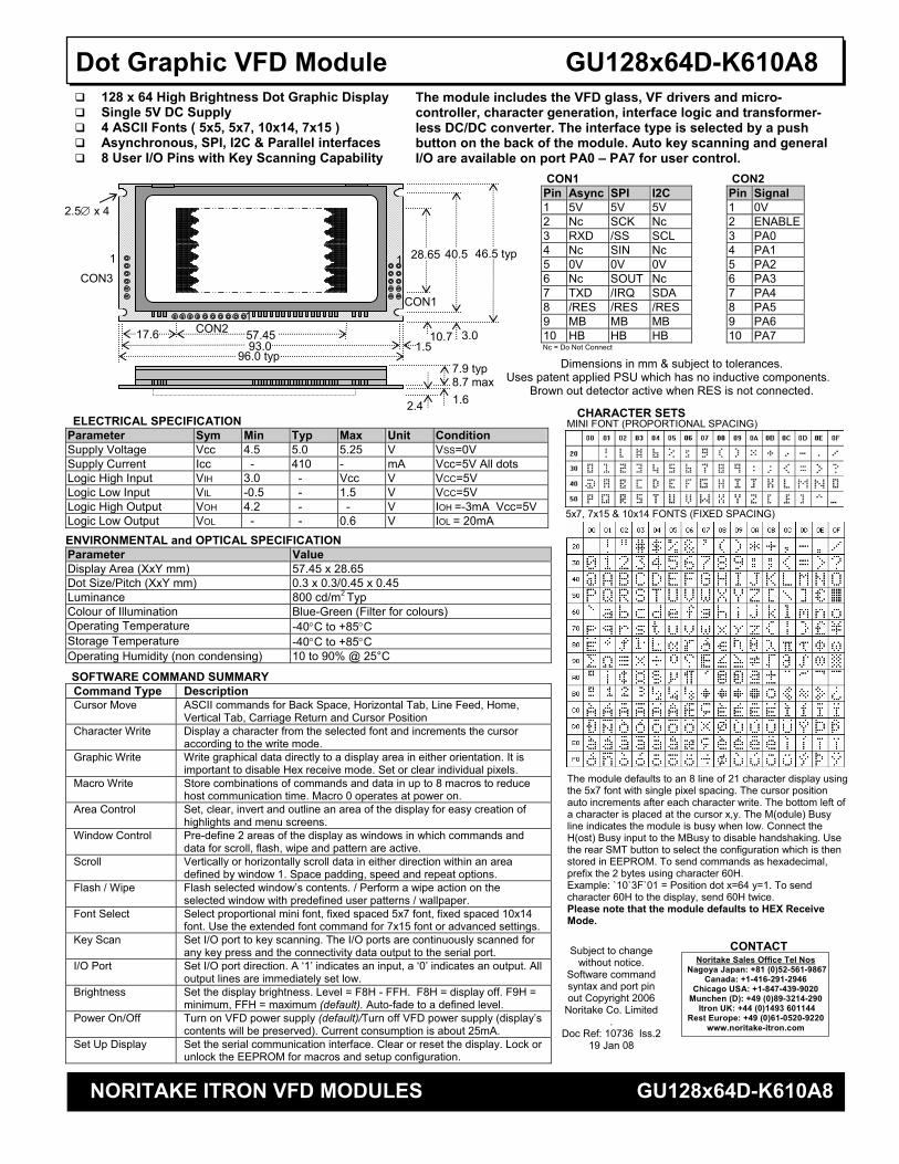
Dimensions in mm & subject to tolerances. Uses patent applied PSU which has no inductive components.
Brown out detector active when RES is not connected.
SOFTWARE COMMAND SUMMARY Command Type Description Cursor Move ASCII commands for Back Space, Horizontal Tab, Line Feed, Home,
Vertical Tab, Carriage Return and Cursor Position Character Write Display a character from the selected font and increments the cursor
according to the write mode. Graphic Write Write graphical data directly to a display area in either orientation. It is
important to disable Hex receive mode. Set or clear individual pixels. Macro Write Store combinations of commands and data in up to 8 macros to reduce
host communication time. Macro 0 operates at power on. Area Control Set, clear, invert and outline an area of the display for easy creation of
highlights and menu screens. Window Control Pre-define 2 areas of the display as windows in which commands and
data for scroll, flash, wipe and pattern are active. Scroll Vertically or horizontally scroll data in either direction within an area
defined by window 1. Space padding, speed and repeat options. Flash / Wipe Flash selected window’s contents. / Perform a wipe action on the
selected window with predefined user patterns / wallpaper. Font Select Select proportional mini font, fixed spaced 5x7 font, fixed spaced 10x14
font. Use the extended font command for 7x15 font or advanced settings. Key Scan Set I/O port to key scanning. The I/O ports are continuously scanned for
any key press and the connectivity data output to the serial port. I/O Port Set I/O port direction. A ‘1’ indicates an input, a ‘0’ indicates an output. All
output lines are immediately set low. Brightness Set the display brightness. Level = F8H - FFH. F8H = display off. F9H =
minimum, FFH = maximum (default). Auto-fade to a defined level. Power On/Off Turn on VFD power supply (default)/Turn off VFD power supply (display’s
contents will be preserved). Current consumption is about 25mA. Set Up Display Set the serial communication interface. Clear or reset the display. Lock or
unlock the EEPROM for macros and setup configuration.
The module includes the VFD glass, VF drivers and micro-controller, character generation, interface logic and transformer-less DC/DC converter. The interface type is selected by a push button on the back of the module. Auto key scanning and general I/O are available on port PA0 – PA7 for user control.
128 x 64 High Brightness Dot Graphic Display Single 5V DC Supply 4 ASCII Fonts ( 5x5, 5x7, 10x14, 7x15 ) Asynchronous, SPI, I2C & Parallel interfaces 8 User I/O Pins with Key Scanning Capability
CHARACTER SETS
46.5 typ40.5
3.0
28.65
57.45 1.5
17.6
96.0 typ 7.9 typ 8.7 max
2.5∅ x 4
1.6
93.0
2.4
10.7CON2
CON1
1
1
CON3
1
The module defaults to an 8 line of 21 character display using the 5x7 font with single pixel spacing. The cursor position auto increments after each character write. The bottom left of a character is placed at the cursor x,y. The M(odule) Busy line indicates the module is busy when low. Connect the H(ost) Busy input to the MBusy to disable handshaking. Use the rear SMT button to select the configuration which is then stored in EEPROM. To send commands as hexadecimal, prefix the 2 bytes using character 60H. Example: `10`3F`01 = Position dot x=64 y=1. To send character 60H to the display, send 60H twice. Please note that the module defaults to HEX Receive Mode.
Subject to change without notice.
Software command syntax and port pin out Copyright 2006
Noritake Co. Limited .
Doc Ref: 10736 Iss.2 19 Jan 08
CON1 Pin Async SPI I2C 1 5V 5V 5V 2 Nc SCK Nc 3 RXD /SS SCL 4 Nc SIN Nc 5 0V 0V 0V 6 Nc SOUT Nc 7 TXD /IRQ SDA 8 /RES /RES /RES 9 MB MB MB 10 HB HB HB
Nc = Do Not Connect
CON2 Pin Signal 1 0V 2 ENABLE3 PA0 4 PA1 5 PA2 6 PA3 7 PA4 8 PA5 9 PA6 10 PA7
CONTACT Noritake Sales Office Tel Nos
Nagoya Japan: +81 (0)52-561-9867Canada: +1-416-291-2946
Chicago USA: +1-847-439-9020 Munchen (D): +49 (0)89-3214-290
Itron UK: +44 (0)1493 601144 Rest Europe: +49 (0)61-0520-9220
www.noritake-itron.com
ELECTRICAL SPECIFICATION Parameter Sym Min Typ Max Unit Condition Supply Voltage Vcc 4.5 5.0 5.25 V VSS=0V Supply Current Icc - 410 - mA Vcc=5V All dots Logic High Input VIH 3.0 - Vcc V VCC=5V Logic Low Input VIL -0.5 - 1.5 V VCC=5V Logic High Output VOH 4.2 - - V IOH =-3mA Vcc=5V Logic Low Output VOL - - 0.6 V IOL = 20mA
ENVIRONMENTAL and OPTICAL SPECIFICATION Parameter Value Display Area (XxY mm) 57.45 x 28.65 Dot Size/Pitch (XxY mm) 0.3 x 0.3/0.45 x 0.45 Luminance 800 cd/m2 Typ Colour of Illumination Blue-Green (Filter for colours) Operating Temperature -40°C to +85°C Storage Temperature -40°C to +85°C Operating Humidity (non condensing) 10 to 90% @ 25°C

NORITAKE ITRON VFD MODULES GU128x64D-K610A8
Dot Graphic VFD Module GU128x64D-K610A8 SOFTWARE COMMANDS
Instruction Data Format Description Macro Start (BUSY time depends on contents)
01H - 07H Start user defined macro 1-7.
Back Space (50µs)
08H Non destructive backspace. Cursor is moved left by the width of the currently select font. If the cursor is at the left end of the display, no cursor movement is made.
Horizontal Tab (50µs)
09H Cursor is moved right by the width of the currently select font. If the cursor is at the end of the display, no cursor movement is made.
Line Feed (50µs)
0AH Moves the cursor down by the height of the currently selected font. If the cursor is at the bottom of the display, no cursor movement is made.
Home (50us)
0BH Moves the cursor horizontal position to 00H, the vertical positioning is dependent on the currently selected font, allowing for immediate character writing in the top-left corner of the display.
Vertical Tab (50us)
0CH Moves the cursor up one character row. If the cursor is at the top of the top end of the display, no cursor movement is made.
Carriage Return (50us)
0DH Moves the cursor horizontal position to 00H. The vertical position is unchanged.
Clear EOL (2.5ms)
0EH Clear all characters from the current cursor position to the end of the display.
Test (50µs)
0FH Place module into self-test mode. The module will repetitively show a few test screens. The test mode will stop on the next received byte.
Cursor Position (50us)
10H + xpos + ypos Set the cursor position.
Set Area (50us + 1ms [last byte])
11H + xleft + ytop + xright + ybot Fill specified area. All dots within the specified area are illuminated. Please note that the cursor position is affected with this command.
Clear Area (50us + 1ms [last byte])
12H + xleft + ytop + xright + ybot Clear specified area. All dots within the specified area are cleared. Please note that the cursor position is affected with this command.
Invert Area (50us + 1ms [last byte])
13H + xleft + ytop + xright + ybot Invert specified area. All dots within the specified area are inverted. Please note that the cursor position is affected with this command.
Set Outline (50us + 1ms [last byte])
14H + xleft + ytop + xright + ybot Draw box outline. All dots within the specified outline are unchanged. Please note that the cursor position is affected with this command.
Clear Outline (50us + 1ms [last byte])
15H + xleft + ytop + xright + ybot Clear box outline. All dots within the specified outline are unchanged. Please note that the cursor position is affected with this command.
Set Pixel (50us)
16H Illuminate a single pixel at the current cursor position.
Clear Pixel (50us)
17H Clear a single pixel at the current cursor position.
Graphic Write (50us + 250us [each data byte])
18H + len + data Write graphical data, length len, direct to display. See write mode command (1AH) for graphic orientation and cursor movements.
Reset (500us)
19H Resets display to power-on defaults: - Display is cleared. 5x7 font selected. Write Mode = 00H Brightness Level = 7. VFD Power = On.
Write Mode (50us)
1AH + data Bit 7 = graphic data orientation - 0 = horizontal, 1 = vertical (default = horizontal) Bit 6 = cursor movement - 0 = horizontal, 1 = vertical (default = horizontal) Bit 5 = cursor direction - 0 = forward, 1 = backwards (default = forwards) Bit 4 = underscore cursor - 0 = off, 1 = on (default = off) Bit 3 = underscore cursor - 0 = static, 1 = flash (default = static) Bit 1/0 = pen type - 00 = overwrite, 01 = AND, 02 = OR, 03 = XOR (default = overwrite)
Set Macro (50us)
1BH + macro + len + data Send macro data to EEPROM. macro = 00H - 07H. Macro0 is executed at power-up only. A maximum of 468 bytes is allowed for macro data. The display may flicker whilst writing macro data.
Brightness (50us)
1BH + level Set the display brightness. level = F8H - FFH. F8H = display off. F9H = minimum, FFH = maximum (default).
Erase Macros (250ms)
1BH + 4DH Clear all downloaded macros in EEPROM. Screen may blank momentarily while macro data is being erased.
Lock/Unlock EEPROM (50us + 40ms [last byte])
1BH + 4CH / 55H All data contained within the non-volatile EEPROM is locked (4CH), and no changes are possible until the unlock command (55H) is executed.
Checksum (50us)
1BH + 43H All data received is added to the checksum. This command will read the lower 8-bits of that checksum, before being cleared. Please note that the checksum is cleared when executing the test mode.
Power On/Off (50us)
1BH + 50H / 46H 50H = Turn on VFD power supply (default). 46H = Turn off VFD power supply, display’s contents will be preserved.
Hex/Binary Mode (50us)
1BH + 48H / 42H 48H = Enable hex receive mode, character 60H is interpreted as a hexadecimal prefix. 42H = Disable hex receive mode. Hex mode is enabled at power up.
Set Serial Comms 1BH + 49H + comms Set Asynchronous Communications. Takes affect at power-up or hardware reset. Bit 7 = Automatic I/O Send On(1)/Off(0). Bit 6 = Packet Mode On(1)/Off(0). Bit 5 = Communications Buffer On(1)/Off(0). Bit 2 = Parity Even(1)/None(0). Bit 3/1/0 baud rate: - 000 = 4800 001 = 9600 010 = 19200 011 = 38400 100 = 57600 101 = 76800 110 = 1200 111 = 2400 Factory Default = 19200 with no parity, auto I/O send is off, packet mode off, buffer = off.
Enable I/O Port (50us + 80ms[last byte])
1BH + 44H + data Set I/O port direction. A ‘1’ indicates an input, a ‘0’ an output. All output lines are immediately set low. All input lines have their pull-ups enabled. This value is stored in EEPROM and will automatically be set at power up.
Set Port Lines (50us)
1BH + 4FH + data Set Output lines on I/O port, a ‘1’ will set 5V on the output ports, or enable the pull-ups on the inputs.
Read Port (50us)
1BH + 52H Read current I/O port status. A single byte is transmitted showing the current state of the I/O lines.
Enable Key Scanning (50us + 40ms[last byte])
1BH + 4BH Set I/O port to key scanning. The I/O ports are continuously scanned for any key press. This mode is stored in EEPROM and will automatically be selected at power up.
Select Font (50us) 1CH / 1DH / 1EH Select font. 1CH = proportional mini font. 1DH= fixed spaced 5x7 font. 1E = fixed spaced 10x14 font. Graphic Area Write (50us + 250us [each data byte])
1FH + xl + yt + xr + yb + data Write graphic data within defined area. See write mode command (1AH) for graphic orientation and cursor movements.
Hex Prefix (50µs + 50us + command BUSY)
60H + dhH + dlH Write to the display module using a 2-byte hexadecimal number. dhH = high nibble, dlH = low nibble. E.g. Sending `19 will reset the display.
Character Write (500us) 20H - FFH Display character from selected font.

NORITAKE ITRON VFD MODULES GU128x64D-K610A8
Dot Graphic VFD Module GU128x64D-K610A8 Window 1 Select (50us) 1BH + 80H Select window 1 so that window and area command functions operate on the underlying data or text scroll. Window 2 Select (50us) 1BH + 81H Select window 2 so that window and area command functions operate on the underlying data. Window Define (50us + 60us[last byte])
1BH + 82H +xl+yt+xr+yb Define window co-ordinates.
Window Mode (50us) 1BH + 83H + mode Set window mode: - 00H = Invert, 01H = Clear, 02H = Fill, 03H = Pattern. Window Show (50us) 1BH + 84H Make selected window visible. Window Flash (50us)
1BH + 86H + no Flash selected window’s underlying data. Flash type depends on window’s write mode. no = number of flashes. FFH = infinite, 00H = stop flashing.
Window Flash Speed (50us)
1BH + 87H + speed Set flash rate of selected window: - 0 = ~15ms 1 = ~30ms 2 = ~45ms 3 = ~100ms 4 = ~150ms 5 = ~200ms 6 = ~250ms 7 = ~350ms 8 = ~500ms 9 = ~750ms 10 = ~1.0sec 11 = ~1.5sec 11 = ~2.0sec 13 = ~2.5sec 14 = ~3.0sec 15 = ~3.5sec Speed bits 4-7 = flash on duration, bits 0-3 = flash off duration. Default speed = 88H (500ms on, 500ms off).
Window Wipe Effect (50us)
1BH + 88H + wipe Perform a wipe action on the selected window’s underlying data: - 00H = left to right cover 01H = right to left cover 02H = top to bottom cover 03H = bottom to top cover 04H = left to right uncover 05H = right to left uncover 06H = top to bottom uncover 07H = bottom to top uncover 08H = horizontal centre to edge cover 09H = horizontal edge to centre uncover 0AH = vertical centre to edge cover 0BH = vertical edge to centre uncover Note: All uncover wipes will alter the window co-ordinates.
Window Wipe Speed (50us)
1BH + 89H + speed Set the wipe effect speed (pixels per second) for the selected window. 00H = halt wipe 01H = ~17Hz 02H = ~35Hz 03H = ~52Hz 04H = ~70Hz 05H = ~87Hz 06H = ~105Hz 07H = ~122Hz 08H = ~140Hz 09H = ~157Hz 0AH = ~175Hz 0BH = ~192Hz 0CH = ~210Hz 0DH = ~227Hz 0EH = ~245Hz 0FH = ~262Hz 10H = ~315Hz The wipe effect duration depends upon the size of the window. Default speed = 04H (~70Hz).
Window Pattern Select (50us)
1BH + 8DH + pat Select pre-defined pattern (00H-0FH) for window: -
Window Pattern Data (50us)
1BH + 8EH + data A user 16x16 pixel pattern (32 bytes) can be defined for the selected window. All data should be in vertical format with D7 uppermost.
Window Pattern Option (50us)
1BH + 8FH + option Window Pattern Options: - Bit 3 = invert pattern data. Bit 2 = pattern alignment on / off. Bit 1 = pattern align with top(1) or bottom(0) of window. Bit 0 = pattern align with left(1) or right edge of window. Default option = 00H (pattern alignment off & not inverted).
Scroll Text In Window 1 (50us + no of data bytes * 50us [last byte])
1BH + 90H + mode + no + data Scroll text data within area defined by window 1. mode bits 1&0 = direction: - 00 = Scroll Up 01 = Scroll Down 10 = Scroll Left 11 = Scroll Right mode bit 4 = scroll window's contents (yes/no) mode bit 5 = pad end of text with spaces (yes/no) no = repeat number (00H = infinite) data = text to be scrolled with 00H = end of text. Use 0DH for multi-line scrolling messages. Up to 8 rows of text can be scrolled horizontally.
Scroll Speed (50us)
1BH + 91H + speed Set window 1 scroll speed (pixels per second): - 00H = halt scroll 01H = ~35Hz 02H = ~70Hz 03H = ~105Hz 04H = ~140Hz 05H = ~175Hz* 06H = ~210Hz* 07H = ~245Hz* 08H = ~315Hz* *Horizontal scroll only. Default speed = 02H (~70Hz).
Select Extended Font (50us)
1BH + 98H + font Select extended font: - bits 0-2 = font number: - 00H = 5x5 ASCII mini font. 01H = 5x7 ASCII font. 02H = 10x14 ASCII font. 03H = 7x15 ASCII font. 04H = 5x7 Cyrillic font. 05H = 10x14 Cyrillic font. bit 3 = proportional / fixed spacing. 1 = proportional, 0 = fixed. bits 4-6 = horizontal font spacing 1-8 pixels, where 000 = 1 pixel through to 111 = 8 pixels.
Auto Fade (50us)
1BH + 9CH + level Perform automatic fade to a defined level. Bits 0-2 = luminance level, where 000 = off through to 111 = 100%. Bits 4-5 = speed, where 00 = fast through to 11 = slow.
Command Delay (50us + delay [last byte])
1BH + 9FH + delay Delay any pending commands: - 00H = wait for display scan to finish. 01H-F0H = multiple of 10ms delay period (10ms to 2.5 seconds). F8H = wait for Scroll to finish. FAH = wait for Window 1 Flash to finish. FBH = wait for Window 2 Flash to finish. FCH = wait for Window 1 Wipe to finish. FDH = wait for Window 2 Wipe to finish. Note: If scroll or flash is set to infinite repeat, the delay is ignored.
Important Notes: - Busy times are not inclusive of a 100us scan period, this must be taken into consideration. If the cursor is enabled, busy times will increase by a further 50us. All coordinates are absolute. The origin (00H, 00H) is the top left of the display. All data shown is in hexadecimal format. The Back Space (08H) command is disabled when using proportional font.

NORITAKE ITRON VFD MODULES GU128x64D-K610A8
Dot Graphic VFD Module GU128x64D-K610A8
RXD
MB
<10us tBUSY
TXD
HB
>2us
GU128x64D-K610A8 SETUP The VFD module features a buffered asynchronous serial port and an unbuffered parallel port at CMOS level. Interface selection/set-up can be made using the single push button switch on the back of the module. Pressing the switch for the first time will display the initial configuration menu. On each subsequent switch press the menu pointer will advance. The current menu item will be selected if the switch is not pressed within 2 seconds. To select the required interface, press the switch until the ‘COMMS’ item has been selected. Wait 2 seconds for the communication menu to be displayed. Press the switch until the required communication method is selected. The factory default interface is “SERIAL”. Wait 2 seconds for the interface menu to be displayed. Press the switch until the required interface is selected. The factory default interface is “SPI”. Wait 2 seconds for the related communication settings and select the property to be edited. Wait 2 seconds to display the related communication settings. The current configuration is displayed first. The factory default settings are “DATA: D7-D0”, “EDGE: RISE:”, “MODE: BUFFER”. Note: Production items can be supplied with the configuration preset and fixed. RESET TIMING The module is reset when a low-level signal is applied to the /RES line. This will cause the Module to clear the display, initialise the communication settings and set all power-up defaults. During this initialisation period, the user must delay any transmission to the module. If the user stores macros in EEPROM, the auto check and repair routine may take up to 9ms per stored byte in addition to the standard reset time. SYNCHRONOUS SERIAL COMMUNICATION (SPI) With synchronous communications enabled, data can be clocked into the VFD module using the rising or falling edge of SCK. This is selectable by the push switch on the rear of the module which also sets the data order. By default, data is clocked in on the rising edge with the most significant bit sent first. The host must provide adequate delays for the module to process the data. These busy times are specified in the software command section. Alternatively the host can monitor the MB (Module Busy) line. The /SS pin can be used as an enable pin if other devices are connected to the SPI bus. The use of the /SS line is optional, and can be permanently pulled low if not required. This is not recommended since /SS ensures synchronisation of the SPI bus. ASYNCHRONOUS SERIAL COMMUNICATION The asynchronous communication speed and parity can be set with the push switch on the rear of the module, or with the ‘SET SERIAL COMMS’ command. The default settings are 19200 baud with no parity. The host busy line (HB) stops the module from sending data to the host until the line falls. The use of the HB and MB lines are optional, and can be connected together if not required.
>1.5us
/RES
DATA 30ms
Reset timing diagram
HOST SYSTEM
GU128x64D-K610A8
CTS MB /RES
RXD TXD
TXD RXD
HB
VDD GND VDD GND
DTR
I/O
D0
D7
D1
D2
D3
D4
D4
D5
D6
PARITY
START
STOP
D0
D7
D1
D2
D3
D4
D4
D5
D6
PARITY
START
STOP
Asynchronous serial communication from host system to VFD module.
Asynchronous serial communication from VFD module to host system.
/SS
SCK (RISING)
D7 SIN (D7-D0)
D6
D0
D7
D6
D0
SCK (FALLING)
D0 SIN (D0-D7)
D1
D7
D0
D1
D7
tBUSY + 10us >125ns
>65ns >125ns
SPI Synchronous Serial Communication.
>125ns
<10us
MB
HOST SYSTEM
GU128x64D-K610A8
I/O /RES
SIN SOUT
I/OI/O
VDD GND VDD GND
SCK I/O
/SS I/OI/O MB
Interface selection example.

NORITAKE ITRON VFD MODULES GU128x64D-K610A8
Dot Graphic VFD Module GU128x64D-K610A8 I2C COMMUNICATION The I2C interface operates as a slave either in ‘slave receive’ or ‘slave transmit’ mode with a fixed address of 70H. A START condition is signaled by driving SDA low while SCL is high. A STOP condition is signaled by driving SDA high while SCL is high. After a START condition is detected followed by ‘SLA+W’ (R/W bit low) with an address of 70H, the command / data bytes may be stored in the serial / packet buffer if selected (command data must not exceed buffer size). The module will pull SDA high during the 9th clock cycle of a data transfer to acknowledge the receipt of a byte. Additional data may be sent after an adequate delay for the module to process the data providing the host receives an Ack. If the host has not detected an Ack the data transfer must be started again by providing a STOP and START condition and SLA+W. When a read command is sent the requested data is buffered then an I2C packet must be sent with SLA+R (R/W bit high) to read the command / data byte(s). The host can monitor the MB (Module Busy) line to provide adequate delays. The SCL and SDA lines are internally pulled up with 10K resistors. PARALLEL COMMUNICATION The 8 I/O lines can be configured as a slow parallel interface. Data on PA0-7 is clocked into the module with the Enable line, this can be set to either a rising or falling edge trigger by the push switch on the back of the module. The host must keep the data stable for the time period indicated in the timing diagram. The module busy line (MB) can be used in parallel communication mode. The input lines D0-D7 are not internally pulled up. The host system should be configured to ensure the stability of these lines. SERIAL BUFFER A 256-byte serial receive buffer can be activated through the setup switch on the rear of the module. This buffer can be used with any of the available serial communication modes. The buffer can also be enabled through the ‘Set Serial Comms’ command (see command table). Once enabled, any I/O data transmitted from the display module due to a read request or automatic I/O read, will be preceded with an identification character. Character 49H (‘I’) precedes I/O data bytes and 43H (‘C’) precedes checksum data bytes. PACKET MODE The packet mode offers a more secure communication for display writing. The packet mode can be used with any of the available serial communication modes. The packet mode can also be enabled through the ‘Set Serial Comms’ command (see command table). Up to 32-bytes of data can be sent to the display module, encapsulated with a header (02H) and footer (03H) byte. The length of the packet should follow the header byte. An 8-bit checksum is used to validate the data. This checksum is the sum of the data bytes. The display acknowledges the packet with a 50H (‘P’) code for successful transfer, or a 45H (‘E’) for a data error. Example packet transfer: - If an error occurs, the display module will discard the data, the host should then re-send the entire packet. If the packet is received correctly, then the data is placed within the 256-byte receive buffer. The receive buffer is enabled automatically when using packet mode.
ENABLE (RISING)
ENABLE (FALLING)
DATA D0 - D7
tBUSY
>125ns
Parallel Communication.
<10us
MB
>250ns >125ns
HOST SYSTEM
GU128x64D-K610A8
ENABLE
PA0-7
VDD GND VDD GND
I/O
I/O MB I/O
HEADER (02H) DATA LENGTH (1-32) DATA CHECKSUM FOOTER (03H) DATA DATA DATA
Packet format.
HEADER
02H 13H 19H 1BH 98H 0BH 10H 00H 0FH “Packet Write” 79H 03H
LENGTH
RESET SELECT FONT SET CURSOR TEXT
FOOTER CHECKSUMDATA
50H
ACKNOWLEDGE BYTE SENT
FROM DISPLAY
HOST SYSTEM
GU128x64D-K610A8
MB VDD GND VDD GND
I/O SDA I/O SCL I/O SDA
SCL
START SLA+W / SLA+R
MSB LSB R/W ACK
1 7 8 9
DATA
MSB LSB ACK
1 8 9
STOP
MB
tBUSY
<10us
>1us
NORITAKE ITRON VFD MODULES GU128x64D-K610A8
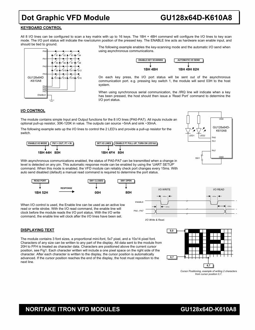
Dot Graphic VFD Module GU128x64D-K610A8 KEYBOARD CONTROL All 8 I/O lines can be configured to scan a key matrix with up to 16 keys. The 1BH + 4BH command will configure the I/O lines to key scan mode. The I/O port status will indicate the row/column position of the pressed key. The ENABLE line acts as hardware scan enable input, and should be tied to ground. I/O CONTROL The module contains simple Input and Output functions for the 8 I/O lines (PA0-PA7). All inputs include an optional pull-up resistor, 30K-120K in value. The outputs can source ~5mA and sink ~30mA.
The following example sets up the I/O lines to control the 2 LED’s and provide a pull-up resistor for the switch. With asynchronous communications enabled, the status of PA0-PA7 can be transmitted when a change in level is detected on any pin. This automatic response mode can be enabled by using the ‘UART SETUP’ command. When this mode is enabled, the VFD module can reliably check port changes every 15ms. With auto send disabled (default) a manual read command is required to determine the port status. When I/O control is used, the Enable line can be used as an active low read or write strobe. With the I/O read command, the enable line will clock before the module reads the I/O port status. With the I/O write command, the enable line will clock after the I/O lines have been set. DISPLAYING TEXT The module contains 3 font sizes, a proportional mini-font, 5x7 pixel, and a 10x14 pixel font. Characters of any size can be written to any part of the display. All data sent to the module from 20H to FFH is treated as character data. Characters are positioned above the current cursor position, see Fig1. Each character written will include a one pixel space on the right side of the character. After each character is written to the display, the cursor position is automatically advanced. If the cursor position reaches the end of the display, the host must reposition to the next line.
The following example enables the key-scanning mode and the automatic I/O send when using asynchronous communications.
GU128x64D-K610A8
S16 S15 S14 S13
S12 S11 S10 S9
S8 S7 S6 S5
S4 S3 S2 S1
PA7 PA6 PA5 PA4
PA3
PA2
PA1
PA0
ENABLE
1BH 4BH
ENABLE KEY SCANNNG
1BH 49H 82H
AUTOMATIC I/O SEND
On each key press, the I/O port status will be sent out of the asynchronous communication port. e.g. pressing key switch 1, the module will send 03H to the host system.
When using synchronous serial communication, the /IRQ line will indicate when a key has been pressed, the host should then issue a ‘Read Port’ command to determine the I/O port status.
1BH 44H 80H
ENABLE I/O MODE
GU128x64D-K610A8
VDD
GND
PA0
PA1
PA7
LED1 LED2
SW1
P0/1 = OUT, P7 = IN
SW1 CLOSED
RESPONSE
1BH 4FH 80H
ENABLE P7 PULL-UP, TURN ON LED1&2
00H
SW1 OPEN
80H
READ PORT
1BH 52H
SET I/O LINES
ENABLE
PA0 - PA7
I/O Write & Read.
~400ns ~400ns
<250ns <250ns
I/O WRITE I/O READ
0,0
0,7
6,7
Cursor Positioning, example of writing 2 characters from cursor position 0,7.
NORITAKE ITRON VFD MODULES GU128x64D-K610A8
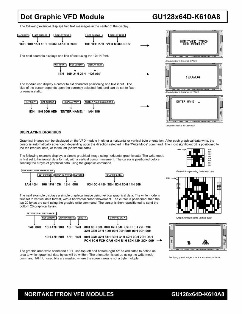
Dot Graphic VFD Module GU128x64D-K610A8 The following example displays two text messages in the center of the display. The next example displays one line of text using the 10x14 font. The module can display a cursor to aid character positioning and text input. The size of the cursor depends upon the currently selected font, and can be set to flash or remain static. DISPLAYING GRAPHICS Graphical images can be displayed on the VFD module in either a horizontal or vertical byte orientation. After each graphical data write, the cursor is automatically advanced, depending upon the direction selected in the ‘Write Mode’ command. The most significant bit is positioned to the top (vertical data) or to the left (horizontal data). The following example displays a simple graphical image using horizontal graphic data. The write mode is first set to horizontal data format, with a vertical cursor movement. The cursor is positioned before sending the 8 byte of graphical data using the graphics command. The next example displays a simple graphical image using vertical graphical data. The write mode is first set to vertical data format, with a horizontal cursor movement. The cursor is positioned, then the top 20 bytes are sent using the graphic write command. The cursor is then repositioned to send the bottom 20 graphical bytes. The graphic area write command 1FH uses top-left and bottom-right XY co-ordinates to define an area to which graphical data bytes will be written. The orientation is set-up using the write mode command 1AH. Unused bits are masked where the screen area is not a byte multiple.
1DH 10H 15H 1FH ‘NORITAKE ITRON’ 10H 1EH 27H ‘VFD MODULES’
5x7 FONT DISPLAY TEXT SET CURSOR DISPLAY TEXT SET CURSOR
1EH 10H 21H 27H ‘128x64’
10x14 FONT DISPLAY TEXTSET CURSOR
1AH 80H 10H 47H 18H 18H 14H 00H 00H 00H 00H 07H 04H C7H FEH 72H 73H 32H 3EH 3FH 1DH 00H 00H 00H 00H 00H 00H
10H 47H 20H 18H 14H 00H 3CH 42H 81H B9H C1H 42H 7CH 20H D8H FCH 3CH FCH CAH 49H B1H 89H 42H 3CH 00H
MSB B
YTE1
B
YTE2
1
BYT
E19
BYT
E2
BYT
E20
BYT
E40
Graphic Image using vertical data
1DH 10H 0DH 0EH ‘ENTER NAME: ’ 1AH 18H
5x7 FONT DISPLAY TEXT ENABLE FLASHING CURSOR SET CURSOR
- 1CH - 5CH - 48H - 3EH - 1DH - 1DH - 14H - 36H
MSB
1AH 40H 10H 1FH 1CH 18H 08H 1CH 5CH 48H 3EH 1DH 1DH 14H 36H
GRAPHIC DATA GRAPHIC WRITE SET CURSOR LENGTH
SET HORIZONTAL WRITE MODE Graphic Image using horizontal data
GRAPHIC DATA GRAPHIC WRITE SET CURSOR LENGTH
SET VERTICAL WRITE MODE
Displaying graphic images in vertical and horizontal format.
Using the cursor to aid user input.
Displaying text in the large 10x14 font.
Displaying text in the small 5x7 font.
NORITAKE ITRON VFD MODULES GU128x64D-K610A8
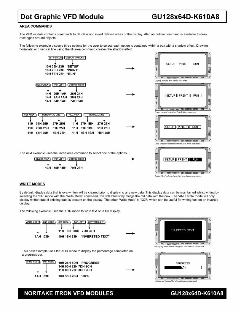
Dot Graphic VFD Module GU128x64D-K610A8 AREA COMMANDS The VFD module contains commands to fill, clear and invert defined areas of the display. Also an outline command is available to draw rectangles around objects. The following example displays three options for the user to select, each option is contained within a box with a shadow effect. Drawing horizontal and vertical line using the fill area command creates the shadow effect. WRITE MODES By default, display data that is overwritten will be cleared prior to displaying any new data. This display data can be maintained whilst writing by selecting the ‘OR’ mode with the ‘Write Mode’ command, this will effectively merge the old data with the new. The ‘AND’ write mode will only display written data if existing data is present on the display. The other ‘Write Mode’ is ‘XOR’ which can be useful for writing text on an inverted display. The following example uses the XOR mode to write text on a full display.
WRITE MODE XOR MODE SET AREA TOP LEFT BOTTOM RIGHT
11H 00H 00H 7DH 3FH
1AH 03H 10H 18H 23H ‘INVERETED TEXT’
Displaying inverted text using the ‘Write Mode’ command.
Using inverting text for displaying progress level.
WRITE MODE XOR MODE 10H 26H 1DH ‘PROGRESS’ 14H 00H 22H 7DH 2CH 11H 00H 22H 3CH 2CH
1AH 03H 10H 38H 2BH ‘50%’
This next example uses the XOR mode to display the percentage completed on a progress bar.
TOP LEFT
SET CURSOR DISPLAY OPTIONS
10H 05H 23H ‘SETUP’ 10H 2FH 23H ‘PRINT’ 10H 5EH 23H ‘RUN’
BOX OUTLINE
14H 00H 1AH 26H 24H 14H 2AH 1AH 50H 24H 14H 54H 1AH 7AH 24H
11H 01H 25H 27H 25H 11H 27H 1BH 27H 25H
11H 2BH 25H 51H 25H 11H 51H 1BH 51H 25H
11H 55H 25H 7BH 25H 11H 7BH 1BH 7BH 25H
BOTTOM RIGHT TOP LEFT BOX OUTLINE BOTTOM RIGHT
HORIZONTAL LINE SET AREA VERTICAL LINE FILL AREA
The next example uses the invert area command to select one of the options.
13H 55H 1BH 79H 23H
TOP LEFT INVERT AREA BOTTOM RIGHT
Option ‘Run’ selected with the ‘Invert Area’ command.
Drop Shadows created with the ‘Set Area’ command.
Boxes created using the ‘Set Outline’ command.
Display options with simple text write.

NORITAKE ITRON VFD MODULES GU128x64D-K610A8
Dot Graphic VFD Module GU128x64D-K610A8 MACROS A string of data and commands can be sent to the module and stored in non-volatile EEPROM by using the macro feature. This string of data and commands can then be executed by using just one command. Up to 8 macros can be used at any one time, one of these is executed at power-up. This example uses the first macro (Macro 0) to display an initial message at power-up. This next example saves the previous graphic icon into Macro 1, and then is used as a user-defined character. This example creates a display template, which can be helpful if many screens require the same look. EEPROM PROTECTION The EEPROM contains information such as macro data, asynchronous communication settings and I/O configuration. So it is important to protect this information from stray commands due to communication failures. To protect the EEPROM, the module contains a ‘EEPROM Lock’ command (1BH + 4CH). Once this command is issued, no further EEPROM updates can be made until it is unlocked (1BH + 55H). This feature is also accessible from the set up menu, using the push button switch on the rear of the module. During reset, EEPROM is automatically checked and repaired. When macros are stored, the module remains busy for 9ms per stored byte. USING THE CHECKSUM All data written to the module is added to an internal checksum. The lower 8-bits of this checksum can be read at any time from the module by the host system to confirm accurate data transfer. It is up to the user if or when this feature should be used. The checksum is cleared at power-up and after each checksum read. Example: Read checksum at power-up, or directly after it has been cleared. Example: Read checksum after data has been written to the display.
1BH 43H
READ CHECKSUM
5EH
CHECKSUM
SENT TO HOST
1BH 43H
READ CHECKSUM
19H 31H 32H 33H
WRITE DATA
SENT TO HOST
0DH
CHECKSUM
POWER-UP MESSAGE
1BH 00H 24H
WRITE TO MACRO-0 LENGTH
10H 1EH 1DH ‘PLEASE WAIT’10H 06H 29H ‘INITIALISING SYSTEM’
Power-Up message using Macro 0.
GRAPHIC DATA
1BH 01H 0CH
WRITE TO MACRO-1 LENGTH
1AH 40H 18H 08H 1CH 5CH 48H 3EH 1DH 1DH 14H 36H
10H 05H 15H 01H 10H 72H 14H 01H 10H 35H 1EH 01H 10H 46H 26H 01H
DISPLAY ICON DISPLAY ICON SET CURSOR SET CURSOR
Using Macros as user-defined characters.
AREA COMMANDS
1BH 02H 1BH
WRITE TO MACRO-2 LENGTH
19H 14H 02H 02H 7BH 3DH 11H 00H 00H 04H 04H 11H 00H 3BH 04H 3FH 11H 79H 00H 7DH 04H 11H 79H 3BH 7DH 3FH
RESET
02H 10H 1CH 23H ‘SYSTEM READY’
DISPLAY TEMPLATE SET CURSOR DISPLAY MESSAGE
Using Macros as a screen template.
NORITAKE ITRON VFD MODULES GU128x64D-K610A8
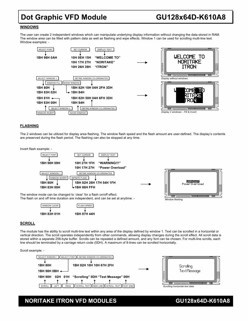
Dot Graphic VFD Module GU128x64D-K610A8 WINDOWS The user can create 2 independent windows which can manipulate underlying display information without changing the data stored in RAM. The window area can be filled with pattern data as well as flashing and wipe effects. Window 1 can be used for scrolling multi-line text. Window examples: - FLASHING The 2 windows can be utilized for display area flashing. The window flash speed and the flash amount are user-defined. The display’s contents are preserved during the flash period. The flashing can also be stopped at any time. Invert flash example: - The window mode can be changed to ‘clear’ for a flash on/off effect. The flash on and off time duration are independent, and can be set at anytime: - SCROLL The module has the ability to scroll multi-line text within any area of the display defined by window 1. Text can be scrolled in a horizontal or vertical direction. The scroll operates independently from other commands, allowing display changes during the scroll effect. All scroll data is stored within a separate 256-byte buffer. Scrolls can be repeated a defined amount, and any font can be chosen. For multi-line scrolls, each line should be terminated by a carriage return code (0DH). A maximum of 8-lines can be scrolled horizontally. Scroll example: -
Display without windows.
SELECT FONT SET CURSOR
10H 17H 27H “NORITAKE” 1BH 98H 0AH 10H 0EH 15H “WELCOME TO”
DISPLAY TEXT
10H 26H 39H “ITRON”
Display 2 windows: - Fill & Invert.
1BH 80H 1BH 82H 10H 04H 2FH 3DH
SELECT WINDOW 1 DEFINE WINDOW CO-ORDINATES
1BH 83H 02H 1BH 84H
WINDOW FILL SHOW WINDOW
1BH 81H 1BH 82H 50H 04H 6FH 3DH
SELECT WINDOW 2 DEFINE WINDOW CO-ORDINATES
1BH 83H 00H 1BH 84H
WINDOW INVERT SHOW WINDOW
1BH 80H 1BH 82H 10H 10H 67H 2FH
SELECT WINDOW 1 DEFINE WINDOW CO-ORDINATES
1BH 98H 0BH
SELECT FONT
1BH 90H 02H 01H “Scrolling” 0DH “Text Message” 00H
SCROLL LEFT ONCE SCROLL TEXT SCROLL TEXTNEW LINE TEXT END Scrolling horizontal text data.
SELECT FONT SET CURSOR
10H 17H 27H “Power Overload” 1BH 98H 09H 10H 27H 1FH “WARNING!!!”
DISPLAY TEXT
1BH 80H 1BH 82H 26H 17H 54H 1FH 1BH 83H 00H 1BH 86H FFH
1BH 83H 01H 1BH 87H 44H
Window flashing.
DEFINE WINDOW CO-ORDINATESSELECT WINDOW 1
WINDOW INVERT INFINITE FLASH
WINDOW CLEAR FLASH SPEED
NORITAKE ITRON VFD MODULES GU128x64D-K610A8
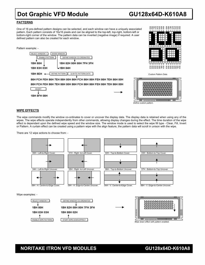
Dot Graphic VFD Module GU128x64D-K610A8 PATTERNS One of 16 pre-defined pattern designs can be selected, and each window can have a uniquely associated pattern. Each pattern consists of 16x16 pixels and can be aligned to the top-left, top-right, bottom-left or bottom-right corner of the window. The pattern data can be inverted (negative image) if required. A user defined pattern can also be created for each window. Pattern example: - WIPE EFFECTS The wipe commands modify the window co-ordinates to cover or uncover the display data. The display data is retained when using any of the wipes. The wipe effects operate independently from other commands, allowing display changes during the effect. The time duration of the wipe effect is dependant upon the defined wipe speed and the window size. The window mode is used to select the wipe fill type - Clear, Fill, Invert or Pattern. A curtain effect can be created using a pattern wipe with the align feature, the pattern data will scroll in unison with the wipe. There are 12 wipe actions to choose from: - Wipe examples: -
86H
FEH
7EH
00H
FCH
86H
86H
86H
86H
FEH
7EH
00H
FCH
86H
86H
86H
FCH
86H
86H
86H
86H
FEH
7EH
00H
FCH
86H
86H
86H
86H
FEH
7EH
00H
Custom Pattern Data.
1BH 80H 1BH 82H 00H 00H 7FH 3FH
SELECT WINDOW 1
DEFINE WINDOW CO-ORDINATES
1BH 83H 03H 1BH 84H
ENABLE PATTERN
SHOW WINDOW
1BH 8EH
86H FCH FEH 86H 7EH 86H 00H 86H FCH 86H 86H FEH 86H 7EH 86H 00H
86H FCH FEH 86H 7EH 86H 00H 86H FCH 86H 86H FEH 86H 7EH 86H 00H
DEFINE PATTERN 32-BYTE PATTERN DATA
Define custom pattern.
1BH 8FH 08H
INVERT
Wipe down effect with pattern enabled.
1BH 80H 1BH 82H 00H 00H 7FH 3FH
SELECT WINDOW 1 DEFINE WINDOW CO-ORDINATES
1BH 83H 03H 1BH 88H 02H
ENABLE WIPE PATTERN START WIPE DOWN EFFECT
00H - Left-to-Right Cover. 01H - Right -to-Left Cover. 02H - Top-to-Bottom Cover. 03H - Bottom-to-Top Cover.
08H - H. Centre-to-Edge Cover. 09H - H. Edge-to-Centre Uncover. 0AH - V. Centre-to-Edge Cover. 0BH - V. Edge-to-Centre Uncover.
04H - Left-to-Right Uncover. 05H - Right -to-Left Uncover. 06H - Top-to-Bottom Uncover. 07H - Bottom-to-Top Uncover.
NORITAKE ITRON VFD MODULES GU128x64D-K610A8
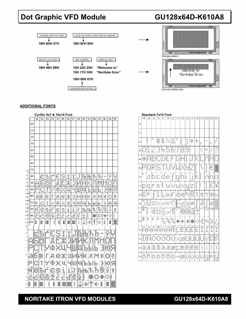
Dot Graphic VFD Module GU128x64D-K610A8 ADDITIONAL FONTS
Change pattern.
Uncover hidden text.
1BH 8DH 07H 1BH 8FH 06H
CHANGE WIPE PATTERN LOCK PATTERN TO BOTTOM OF WINDOW
SELECT 7x15 FONT SET CURSOR
10H 17H 30H “Noritake Itron” 1BH 98H 0BH 10H 22H 20H “Welcome to”
DISPLAY TEXT
1BH 88H 07H
UNCOVER WIPE EFFECT
Cyrillic 5x7 & 10x14 Font Standard 7x15 Font