dosimetry for flattening filter free (fff) linac beams and ... · pdf filewhat is npl doing...
TRANSCRIPT
Dosimetry for Flattening Filter Free (FFF)
linac beams and small fields (SF)
Simon Duane
Principal Research Scientist
Radiation Dosimetry group
National Physical Laboratory
2nd December 2013
Outline
What is NPL doing to support FFF and SF?
Primary and secondary standards
Dissemination and codes of practice
Audit and training
Some dosimetry issues
FFF (including TomoTherapy):
beam profile
beam quality and quality index
dose rate
SF:
perturbation effects
What is NPL doing (i)
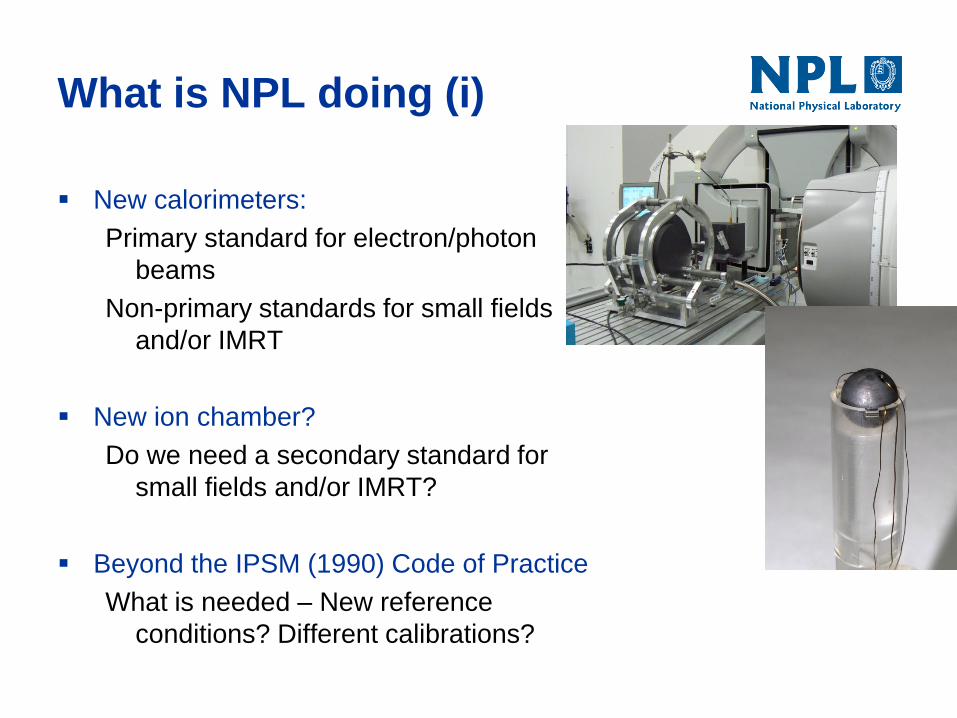
New calorimeters:
Primary standard for electron/photon
beams
Non-primary standards for small fields
and/or IMRT
New ion chamber?
Do we need a secondary standard for
small fields and/or IMRT?
Beyond the IPSM (1990) Code of Practice
What is needed – New reference
conditions? Different calibrations?
What is NPL doing (ii)
Audit
Development ongoing (IMRT, rotational, SABR, …)
Training
Practical Course in Reference Dosimetry (PCRD) is evolving –
since 2013, MV module covers small field issues
New course at NPL (13 May 2014):
Dosimetry for Advanced Radiotherapy Techniques
Also on-site delivery of training, e.g. as part of an audit visit;
And eLearning, e.g. to complement PCRD.
Dosimetry issues: (i) FFF
Simple-minded questions:
FFF beam isn’t flat – uniformity corrections needed?
FFF beam is less filtered – affects spectrum / quality?
FFF beam is less attenuated – dose rate issues?
Dosimetry issues: (ii) SF
What makes a small field small, and what are the issues?
Penumbrae may overlap
source occlusion
Lateral disequilibrium effects
If penumbrae don’t overlap
Detector may still be too big to fit between them
FFF – a brief reminder
An FFF beam is not conventionally flattened
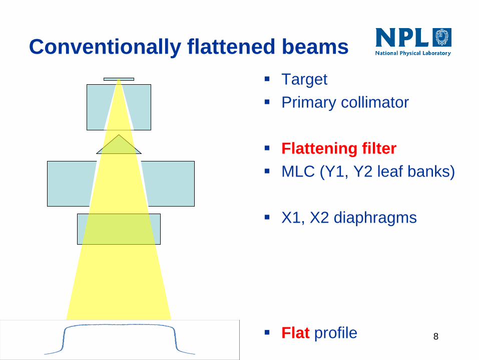
Conventionally flattened beams
Target
Primary collimator
Flattening filter
MLC (Y1, Y2 leaf banks)
X1, X2 diaphragms
Flat profile 8
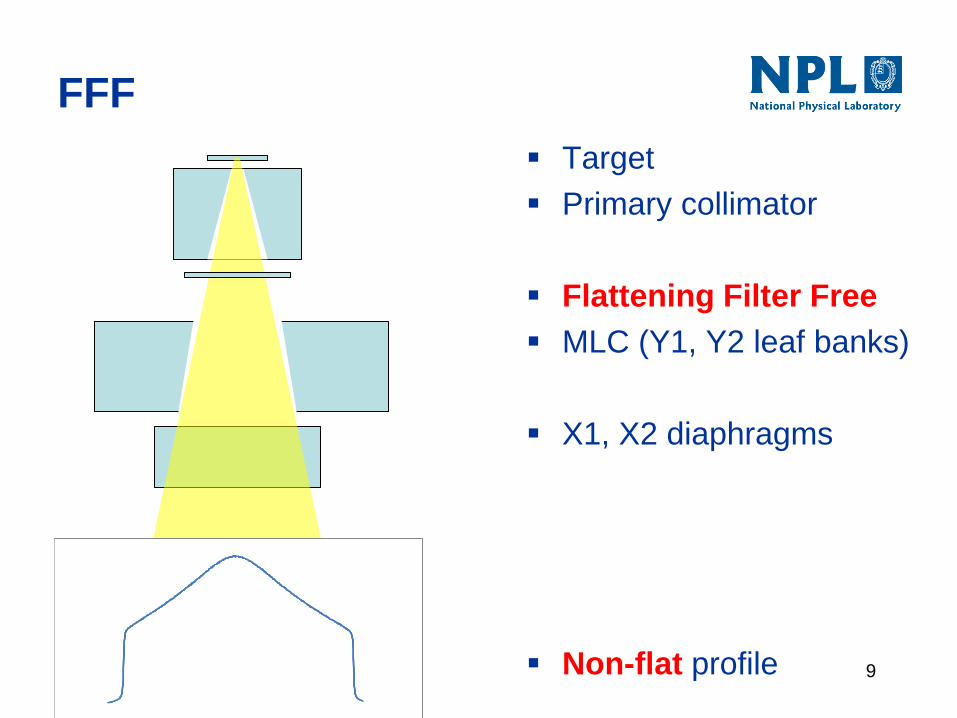
FFF
Target
Primary collimator
Flattening Filter Free
MLC (Y1, Y2 leaf banks)
X1, X2 diaphragms
Non-flat profile 9
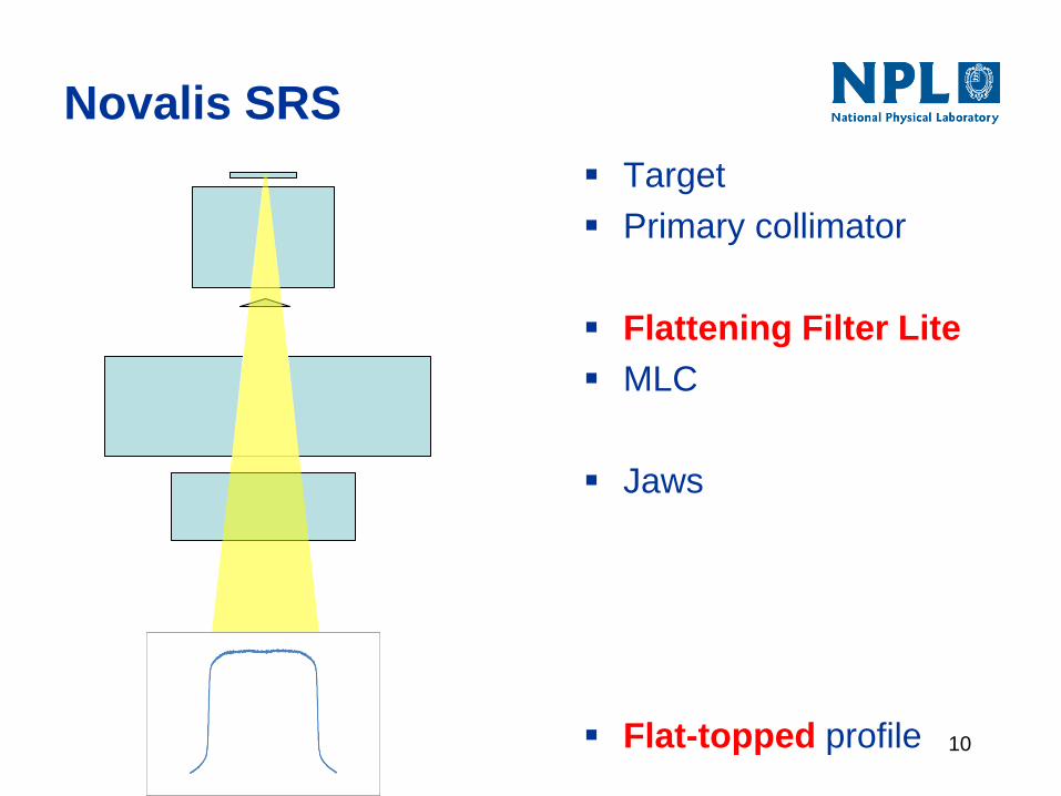
Novalis SRS
Target
Primary collimator
Flattening Filter Lite
MLC
Jaws
Flat-topped profile 10
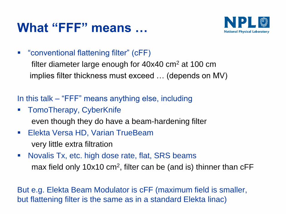
What “FFF” means …
“conventional flattening filter” (cFF)
filter diameter large enough for 40x40 cm2 at 100 cm
implies filter thickness must exceed … (depends on MV)
In this talk – “FFF” means anything else, including
TomoTherapy, CyberKnife
even though they do have a beam-hardening filter
Elekta Versa HD, Varian TrueBeam
very little extra filtration
Novalis Tx, etc. high dose rate, flat, SRS beams
max field only 10x10 cm2, filter can be (and is) thinner than cFF
But e.g. Elekta Beam Modulator is cFF (maximum field is smaller,
but flattening filter is the same as in a standard Elekta linac)
Return of the FFF beams…
Once upon a time, NPL linac beams were a bit like FFF.
Today, NPL determines ND,w,Q for use in beams with a
conventional flattening filter
Reference standard validated using existing primary
standard calorimeter in all our flat Elekta beams
New primary standard calorimeter currently being
commissioned – initially in all flat beams, then in
FFF beams (various setups)
Dosimetry issues: (i) FFF
Simple-minded questions:
FFF beam isn’t flat – uniformity corrections needed?
FFF beam is less filtered – affects spectrum / quality?
FFF beam is less attenuated – dose rate issues?
Beam uniformity correction
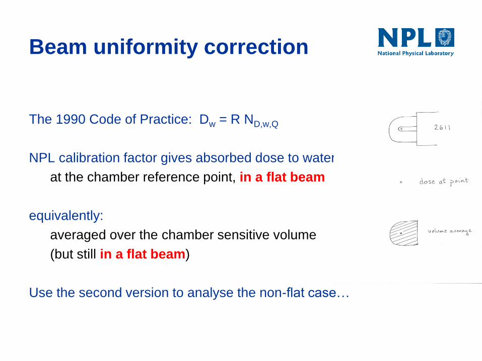
The 1990 Code of Practice: Dw = R ND,w,Q
NPL calibration factor gives absorbed dose to water
at the chamber reference point, in a flat beam
equivalently:
averaged over the chamber sensitive volume
(but still in a flat beam)
Use the second version to analyse the non-flat case…
Uniformity correction estimate
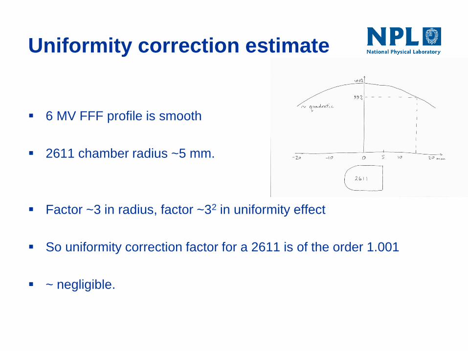
6 MV FFF profile is smooth
2611 chamber radius ~5 mm.
Factor ~3 in radius, factor ~32 in uniformity effect
So uniformity correction factor for a 2611 is of the order 1.001
~ negligible.
Dosimetry issues: (i) FFF
Simple-minded questions:
FFF beam isn’t flat – uniformity corrections needed?
FFF beam is less filtered – affects spectrum / quality?
FFF beam is less attenuated – dose rate issues?
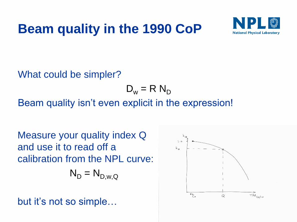
Beam quality in the 1990 CoP
What could be simpler?
Dw = R ND
Beam quality isn’t even explicit in the expression!
Measure your quality index Q
and use it to read off a
calibration from the NPL curve:
ND = ND,w,Q
but it’s not so simple…
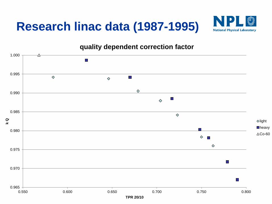
Research linac data (1987-1995)
0.965
0.970
0.975
0.980
0.985
0.990
0.995
1.000
0.550 0.600 0.650 0.700 0.750 0.800
k Q
TPR 20/10
quality dependent correction factor
light
heavy
Co-60
NPL Dw service – what happened
Ancient history:
Service launched 1988:
beams from research linac
FF only 3 mm – 5 mm thick
max field only ~10x10 cm2
Calibration curve “looked odd“ 60Co and 4 MV ~0.6% different
Beam hardening added, 5 cm – 14 cm aluminium
1989: 12 MV – 19 MV and
1992: 4 MV – 10 MV:
Calibration curve “looked ok”
Remarks
As long as all clinical beams are similar (flat), NPL
calibration beams can match them (all):
Life is simple for secondary standard users, but…
The Dw calibration is only valid for flat beams.
But FFF beams will become increasingly common.
What can we do?
Extend our calibration beams to include FFF and
extend the scope of our primary standard.
Quantify the correction for filtration.
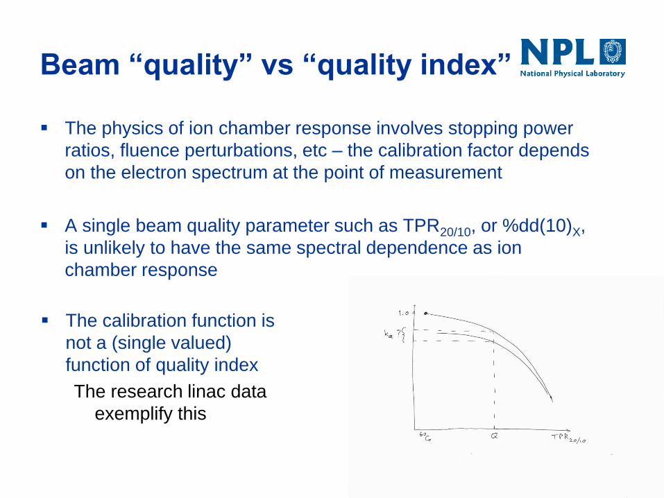
Beam “quality” vs “quality index”
The physics of ion chamber response involves stopping power
ratios, fluence perturbations, etc – the calibration factor depends
on the electron spectrum at the point of measurement
A single beam quality parameter such as TPR20/10, or %dd(10)X,
is unlikely to have the same spectral dependence as ion
chamber response
The calibration function is
not a (single valued)
function of quality index
The research linac data
exemplify this
Dosimetry issues: (i) FFF
Simple-minded questions:
FFF beam isn’t flat – uniformity corrections needed?
FFF beam is less filtered – affects spectrum / quality?
FFF beam is less attenuated – dose rate issues?
FFF dose rate
Elekta nominal 2400 MU/min (10MV, 400Hz) is
0.1MU per pulse.
Ion recombination ~2.4% for a 2611 at -200V,
compared to ~0.9% in a flat beam (400 MU/min for
10MV, 200Hz)
This correction must be determined carefully for
good uncertainty. The two voltage method works,
as does the formula in terms of dose per pulse.
Dosimetry for FFF - summary
Beam profile effects
Small. Of the order 0.1% in 6 MV FFF.
Beam quality effects
Important in principle, but unlikely to exceed 0.5%
Dose rate effects
Ion recombination must be corrected – otherwise the
error could be up to 2.4%.
What is NPL doing (i)
New calorimeters:
Primary standard for electron/photon beams
Non-primary standards for small fields and/or IMRT
New ion chamber?
Do we need a secondary standard for small fields and/or
IMRT?
Beyond the IPSM (1990) Code of Practice
What is needed – New reference conditions? Different
calibrations?
New calorimeters
Primary standard for electron / photon beams
More robust (an ~identical calorimeter now travels to
proton and ion beam facilities a few times a year)
Lots more sensors, heaters
Still being characterised in flat beams (FFF beams
will follow)
Small field / IMRT calorimeter (prototypes)
Simpler devices; calibrated in water; details of use in
small fields still being explored…
A new reference chamber?
Depends how reference dosimetry develops in UK:
If we go beyond IPSM 1990 (small fields, IMRT), we
may need a new reference chamber.
For TomoTherapy dosimetry, the 2611 is ok, and a
new addendum will recommend this.
A new project, starting in Jan ’14, will look at what is
would be required to provide support for a likely
successor to the 1990 Code of Practice
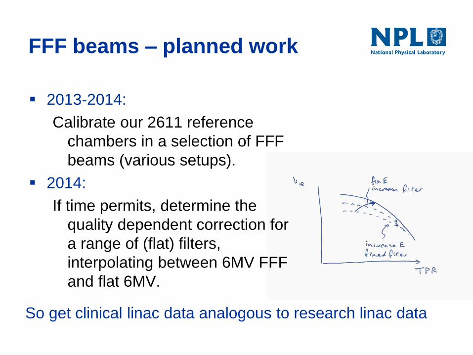
FFF beams – planned work
2013-2014:
Calibrate our 2611 reference
chambers in a selection of FFF
beams (various setups).
2014:
If time permits, determine the
quality dependent correction for
a range of (flat) filters,
interpolating between 6MV FFF
and flat 6MV.
So get clinical linac data analogous to research linac data
What is NPL doing (ii)
Audit
Development ongoing (IMRT, rotational, SABR, …)
Training
Practical Course in Reference Dosimetry (PCRD) is evolving –
since 2013, MV module covers small field issues
New course (13 May 2014):
Dosimetry for Advanced Radiotherapy Techniques
Also on-site delivery of training, e.g. as part of an audit visit;
And eLearning, e.g. to complement PCRD.
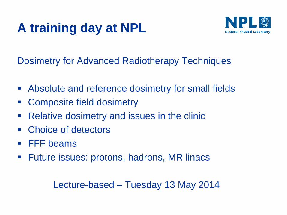
Dosimetry for Advanced Radiotherapy Techniques
Absolute and reference dosimetry for small fields
Composite field dosimetry
Relative dosimetry and issues in the clinic
Choice of detectors
FFF beams
Future issues: protons, hadrons, MR linacs
Lecture-based – Tuesday 13 May 2014
A training day at NPL
What is NPL doing (ii)
Audit
Development ongoing (IMRT, rotational, SABR, …)
Training
Practical Course in Reference Dosimetry (PCRD) is evolving –
since 2013, MV module covers small field issues
New course at NPL (13 May 2014):
Dosimetry for Advanced Radiotherapy Techniques
Also on-site delivery of training, e.g. as part of an audit visit;
And eLearning, e.g. to complement PCRD.
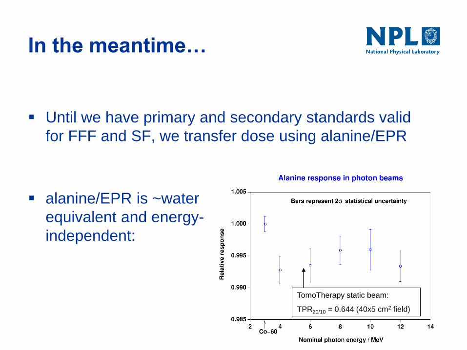
Until we have primary and secondary standards valid
for FFF and SF, we transfer dose using alanine/EPR
In the meantime…
TomoTherapy static beam:
TPR20/10 = 0.644 (40x5 cm2 field)
alanine/EPR is ~water
equivalent and energy-
independent:
An example of FFF:
dosimetry for TomoTherapy
Rely on quality-independence of alanine/EPR
Calibrate 2611 and A1SL chambers on-site
There is no code of practice
We made something up:
Measure relevant fields (helical treatments)
Assume nothing about machine performance
“Black box” integrates treatment plan and delivery
FFF-specific issues
It’s a learning experience. What did/do we expect?
Issues expected
Beam profile
The beam isn’t flat
but the open field profile is rather smooth – effect is small
Beam quality
No flattening filter means altered spectrum. Tomo
has a beam hardener. Expect the effect to lie
between old NPL “light” and “heavy” beams
Dose rate
Is high: measure recombination. Chamber 2611 is
well-behaved: dose per pulse formula works.
Outcome
A Tomo beam quality index equivalent to TPR20/10
can be derived from measurements in 5x10 cm2
Cannot use the raw TPR value of the small field to
evaluate ND,w,Q from NPL calibration
Beam quality is not a significant issue
The correction for any additional change in 2611
response associated with the change in beam
filtration can be taken as 1.000
TomoTherapy and the 1990 CoP
IPEM RTSIG WP has prepared, with NPL input
An addendum to the 1990 Code of Practice for MV
photon dosimetry.
restricted scope - tomotherapy only
adopts IAEA formalism (Alfonso et al.)
NE2611 remains the recommended chamber
deals with non-standard reference conditions
Arguably, we need a more substantial revision to /
replacement for the 1990 code.
Is the 1990 CoP too simple?
Perhaps users can’t be protected from the change in
beam quality between calibration and measurement.
Where known, the effect of the change has so far
turned out to be small. In general?
Aside from TPR20/10 and %dd(10)X , what could a
user determine to find out if a chamber calibration is
valid for the planned measurement?
Dosimetry issues: (ii) SF
What makes a small field small, and what are the issues?
Penumbrae may overlap
source occlusion (source has a finite size)
Lateral disequilibrium effects (electron transport)
If penumbrae don’t overlap
Detector may still be too large to fit between them
080915
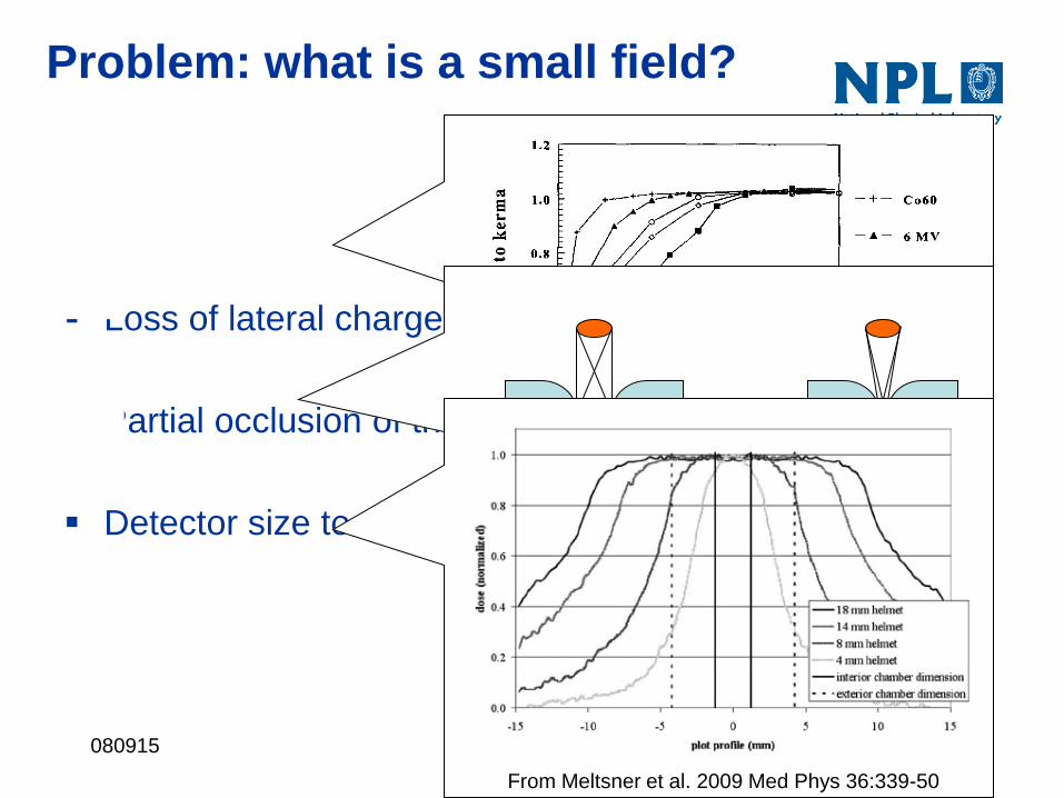
Loss of lateral charged particle equilibrium
Partial occlusion of the primary source
Detector size too large
Problem: what is a small field?
Li et al. 1995 Med Phys 221167-70
From Meltsner et al. 2009 Med Phys 36:339-50
080915
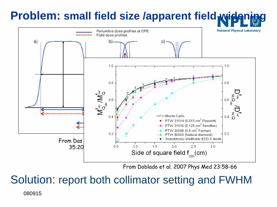
Problem: small field size /apparent field widening
From Das et al. 2008 Med Phys 35:206-15
From Doblado et al. 2007 Phys Med 23:58-66
Solution: report both collimator setting and FWHM
080915
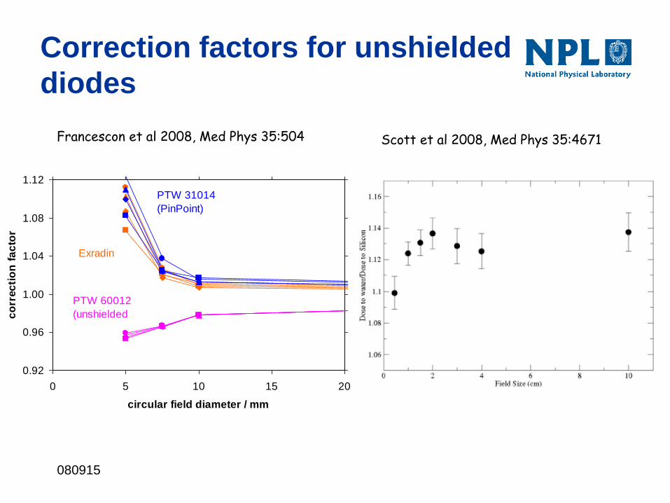
Correction factors for unshielded
diodes
Francescon et al 2008, Med Phys 35:504 Scott et al 2008, Med Phys 35:4671
0.92
0.96
1.00
1.04
1.08
1.12
0 5 10 15 20
circular field diameter / mm
co
rrec
tio
n f
ac
tor
Exradin
PTW 31014
(PinPoint)
PTW 60012
(unshielded
diode)
Water equivalence in small fields
Charged particle equilibrium in a detector requires
that out-scattering matches in-scattering: this
depends on electron range and matched medium
densities is the key.
Silicon diodes have a higher density than water and
over-respond on the central axis of very small fields.
Air filled ion chambers under-respond.
Optimising SF detector response
Pay attention to medium densities and the
arrangement of of high and low-density regions.
Try to make disequilibrium effects tend to cancel.


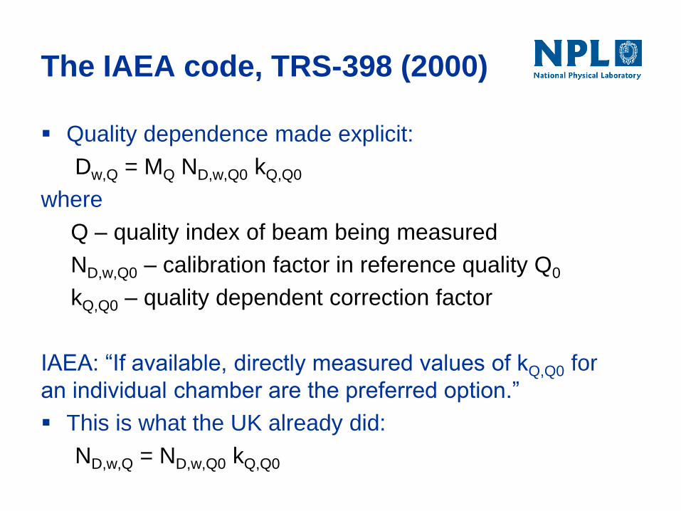
The IAEA code, TRS-398 (2000)
Quality dependence made explicit:
Dw,Q = MQ ND,w,Q0 kQ,Q0
where
Q – quality index of beam being measured
ND,w,Q0 – calibration factor in reference quality Q0
kQ,Q0 – quality dependent correction factor
IAEA: “If available, directly measured values of kQ,Q0 for
an individual chamber are the preferred option.”
This is what the UK already did:
ND,w,Q = ND,w,Q0 kQ,Q0
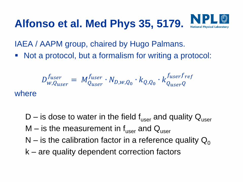
Alfonso et al. Med Phys 35, 5179.
IAEA / AAPM group, chaired by Hugo Palmans.
Not a protocol, but a formalism for writing a protocol:
𝐷𝑤,𝑄𝑢𝑠𝑒𝑟
𝑓𝑢𝑠𝑒𝑟 = 𝑀𝑄𝑢𝑠𝑒𝑟
𝑓𝑢𝑠𝑒𝑟 ∙ 𝑁𝐷,𝑤,𝑄0 ∙ 𝑘𝑄,𝑄0 ∙ 𝑘𝑄𝑢𝑠𝑒𝑟𝑄𝑓𝑢𝑠𝑒𝑟𝑓𝑟𝑒𝑓
where
D – is dose to water in the field fuser and quality Quser
M – is the measurement in fuser and Quser
N – is the calibration factor in a reference quality Q0
k – are quality dependent correction factors
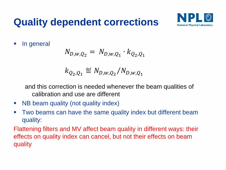
Quality dependent corrections
In general
𝑁𝐷,𝑤,𝑄2 = 𝑁𝐷,𝑤,𝑄1 ∙ 𝑘𝑄2,𝑄1
𝑘𝑄2,𝑄1 ≝ 𝑁𝐷,𝑤,𝑄2 𝑁𝐷,𝑤,𝑄1
and this correction is needed whenever the beam qualities of
calibration and use are different
NB beam quality (not quality index)
Two beams can have the same quality index but different beam
quality:
Flattening filters and MV affect beam quality in different ways: their
effects on quality index can cancel, but not their effects on beam
quality
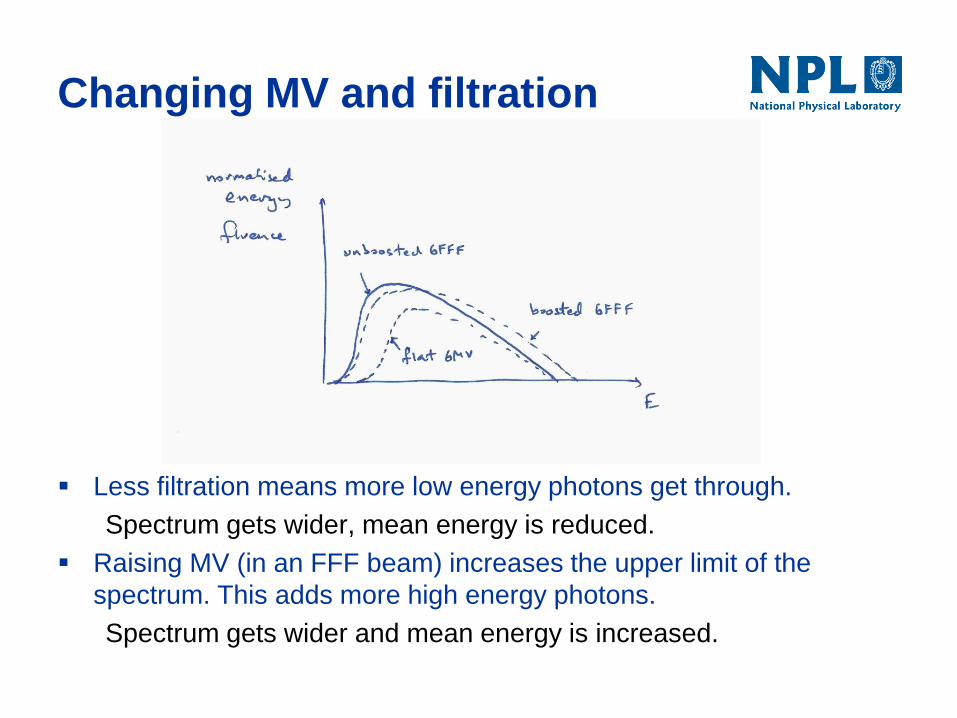
Changing MV and filtration
Less filtration means more low energy photons get through.
Spectrum gets wider, mean energy is reduced.
Raising MV (in an FFF beam) increases the upper limit of the
spectrum. This adds more high energy photons.
Spectrum gets wider and mean energy is increased.