dos attacks prevention techniques in public - department lor
TRANSCRIPT

"An overview of Denial of Service Issues
and Solutions in operators networks"
Olivier Paul RST department/TSP
19/09/2011
Disclaimer
• This presentation is
*not* meant to be
complete.

DoS Attacks definitions
Source Definition
ISO 7498-2 [ISO89] “The prevention of authorised access to
resources or the delaying of time of critical
operations.”
NIST [Ols95] “Actions that prevent a network element
from functioning in accordance with its
intended purpose. Network elements may be
rendered partially or entirely unusable for
legitimate users. Denial of service may
cause operations which depend on
timeliness to be delayed.”
CERT [CERT97] “A denial-of-service attack is characterised
by an explicit attempt by attackers to
prevent legitimate users of a service from
using that service”
Introduction
Mitigation
Conclusion

Agenda
• Introduction
– DoS attacks taxonomy
– Some figures.
• Existing DoS mitigation schemes
– 4 main phases
– Mainly carriers/operator networks oriented
• Conclusion
Introduction
Mitigation
Conclusion

DoS taxonomy
• Degree of indirection
Introduction
Mitigation
Conclusion
Internet TCP SYN TCP SYN TCP SYN
TCP SYN TCP SYN
TCP SYN
TCP SYN
TCP SYN
Computer A
Computer B

DoS taxonomy
• Degree of indirection
Introduction
Mitigation
Conclusion
Internet
Attack B
Attack C
Attacker Master
Slave A
Slave B
Slave C
Slave D
Victim B Victim C
Attack B
Attack B Attack C
Attack B

DoS taxonomy
• Degree of reflection
Introduction
Mitigation
Conclusion
Internet
Source Address: C
Dest. Address : B
Attacker (A) Deflector (B)
Victim (C)
Source Address: B
Dest. Address: C

DoS classification criterion
• Mirkovic & al., SIGCOMM CCR 04
– Source Address validity
• Spoofed Address
• Valid address
– Characterization
• Characterizable.
– Filterable.
– Non Filterable.
• Non characterizable
Introduction
Mitigation
Conclusion

DoS classification criterion
• Mirkovic & al., SIGCOMM CCR 04
– Victim type
• Application
• Operating system
• Resource
• Network
– Exploited Vulnerability
• Semantic
– Design level
– Implementation level
• Brute force
Introduction
Mitigation
Conclusion

DoS classification criterion
• Mirkovic & al., SIGCOMM CCR 04
– Rate dynamics
• Constant Rate
• Variable Rate
– Increasing.
– Decreasing.
– Fluctuating.
– Impact
• Disruptive.
– Self recoverable.
– Human recoverable.
– Non recoverable.
• Degrading.
• None.
Introduction
Mitigation
Conclusion

DDoS classification criterion
• Mirkovic & al., SIGCOMM CCR 04
– Attack Networks Model
• Agent Based. Slave-Master Model (eg: TFN2K).
• Server based:
– IRC Based. Use IRC servers for communications (eg: Agobot).
– P2P based. Registers with cache servers. Use P2P protocol for
communication (eg: Phatbot: Gnutella + WASTE)
– Degree of automation
• Relates to the various phases in a DDoS attack:
– scanning,
– exploitation,
– installation,
– attack control
• Manual, Semi-Automated, Fully Automated
Introduction
Mitigation
Conclusion

DDoS Tools
• Usually integrate several type of attacks
• Example: TFN2K, Released in 1999.
– Integrates:
• ICMP Flood, UDP Flood, TCP SYN Flood,
• SMURF. Use broadcast as address destination address and victim address as
source.
• Targa3. Use uncommon IP packets to exploit vulnerabilities in protocol
stacks.
• Able to send mixed attacks.
– Slave-Master Model
• Uses CAST-256 encryption between master and slaves.
• Communication using a protocol (UDP, ICMP, TCP) chosen randomly.
• Does not use acknowledgements.
Introduction
Mitigation
Conclusion

Are there a lot of attacks ?
• Backscatter Analysis
– Inferring DoS Attacks (Moore & al., USENIX 01)
– Trends in DoS Attacks (Nazario, Usenix Security 03)
• /8 network.
• 10-30k attacks per week.
• 2001,2002: 75% TCP, 2003: 90% UDP.
• Duration from 1s to one day, 10% > 10 minutes.
• 2% > 100k packets, 0.5% > 1M packets.
Introduction
Mitigation
Conclusion

An expending business ?
• From NANOG mailing List: Date: Thu, 3 Jun 2004 23:32:19 -0700
From: <NANOG Mailing list>
Dear sirs.
We are glad to you to give qualitative service, on elimination
of sites. We can kill any site by our attack, which have name
'DDos attack’ <…>
The prices at us are low, 60 dollars for 6 hours. 150 dollars a
day. Destroy any project on the Internet with the help of
ours DDos service. Payment prinimaetsja in system WebMoney.
Introduction
Mitigation
Conclusion

Attacks figures
Introduction
Mitigation
Conclusion
Source: Craig Labovitz, Bots, DDoS and Ground Truth. NANOG 50, 2010.
• Size (Overall)
• Size (Flooding)

Attacks figures
Introduction
Mitigation
Conclusion
Source: Craig Labovitz, Bots, DDoS and Ground Truth. NANOG 50, 2010.
• Target

Attacks figures
Introduction
Mitigation
Conclusion
Source: Craig Labovitz, Bots, DDoS and Ground Truth. NANOG 50, 2010.
• Duration
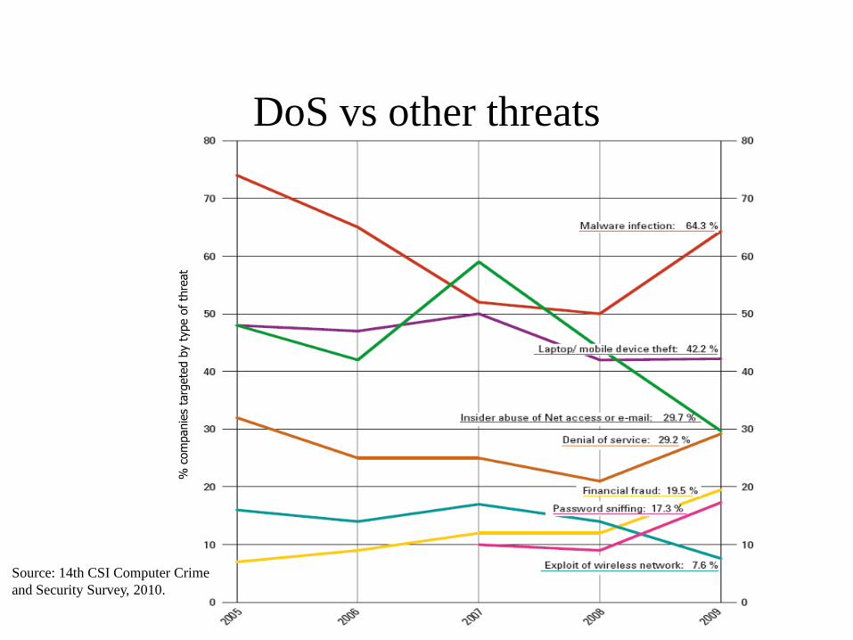
DoS vs other threats
Source: 14th CSI Computer Crime
and Security Survey, 2010.
% c
om
panie
s ta
rgete
d b
y t
ype o
f th
reat

DoS mitigation techniques
• Usually divided in four phases:
– Prevention
– Detection
– Tracking
– Suppression
– (Post Mortem)
Introduction
Mitigation
Conclusion
Detection Prevention Suppression Tracking

Prevention
• Customer side
• Design more resilient protocols.
• Implement more resilient software.
• Protect end hosts (patching, anti virus, firewall).
• Public network side
• Block well known protocol/ports/address ranges during outbreaks.
• Address spoofing prevention.
– Ingress filtering/RPF.
– Hop count based filtering (Jin & al. CCS 2003).
– Source Address Validation (Li & al. INFOCOM 2002).
Introduction
Mitigation
Conclusion Prevention
Detection
Tracking
Suppression

More resilient protocols
• TCP cookies
Introduction
Mitigation
Conclusion Prevention
Detection
Tracking
Suppression
Sequence Number = AN_R = SN_S + 1
Acknowledgment Number = SN_R + 1
Destination Port (DP_S)
Windows (W_S)
Urgent Pointer
/
Offset
Source Port (SP_S)
Reserv.
Checksum
Flags
Sequence Number (SN_S)
Acknowledgment Number = 0
Destination Port (DP_S)
Windows (W_S)
Urgent Pointer
Options(MSS_S)
Offset
Source Port (SP_S)
Reserv.
Checksum
Flags
SYN (S->R)
ACK (S->R)
Sequence Number (SN_R)
Acknowledgment Number (AN_R = SN_S + 1)
Destination Port = (DP_R = SP_S)
Windows (W_R)
Urgent Pointer
Options(MSS_R)
Offset
Source Port (SP_R = DP_S)
Reserv.
Checksum
Flags
SYN/ACK (R->S)
Sequence Number = SN_R + 1
Acknowledgment Number = SN_S + 1
Destination Port (DP_R)
Windows (W_R)
Urgent Pointer
/
Offset
Source Port (SP_R)
Reserv.
Checksum
Flags
ACK (R->S)
Red fields need to be recovered

More resilient protocols
• TCP cookies
– Store information in SN_R :
Introduction
Mitigation
Conclusion Prevention
Detection
Tracking
Suppression
Co=counter%32 T(MSS_S) H=Hash(SA_S, SP_S, DA_S, DP_S, counter, secret)
5 bits 3 bits 24 bits
– SA_S, DA_S: source/destination IP addresses.
– T(MSS_S) codes most common values on MSS on 3 bits.
– When receiving ACK :
– Check that H = H=Hash(SA_S, SP_S, DA_S, DP_S, counter, secret)
for recent counter values.
– Compute SN_S by subtracting 1 to sequence number.
– Recover MSS_S = T-1(T(MSS_R)).
– SP_S is unchanged.

Ingress Filtering
• IETF BCP 38 • Restrict the scope of addresses that can be used by the attacker.
• Use ACL on routers.
Introduction
Mitigation
Conclusion Prevention
Detection
Tracking
Suppression
Attacker
Network
R
Internet
Filter
Victim
User
C
B
A
F
I1
I2

Ingress Filtering
• IETF BCP 38 • High in the network. Increase
spoofing ability.
• Low in the network. Increase
management burden.
• Some protocol need to use
foreign address (e.g. Mobile IP)
• Some other protocols need to use
special addresses (e.g. BOOTP)
• Some performance issues.
• Not widely implemented.
Introduction
Mitigation
Conclusion Prevention
Detection
Tracking
Suppression
Attacker
Networ
k
R
Internet
Filter
Victim
User
C
B
A
F
I1
I2

uRPF
• Unicast Reverse Path Forwarding • Or … how to use routers architecture smartly
Routing
Processor
FIB FIB FIB FIB FIB FIB FIB FIB Line Cards
Router Routing
Processor
Juniper M160
Ports
Other routers
Introduction
Mitigation
Conclusion Prevention
Detection
Tracking
Suppression
RIB

uRPF
• Unicast Reverse Path Forwarding • Use FIB information to build filtering rules automatically.
• No rule at all, Just use the FIB !
• No performance issues.
Introduction
Mitigation
Conclusion Prevention
Detection
Tracking
Suppression
Attacker Network
R
Internet
Filter
Victim
User
C
B
A
F
I1
I2
Destination Outgoing Interface
A I2
R I1

uRPF
• uRPF (Unicast Reverse Path Forwarding)
– Various modes
• Strict mode.
– Check that the receiving interface is the shorter to the source.
– Does not support asymmetric routes or multi-homing.
• Loose mode.
– Check that the receiving interface knows a path to the source.
– Less secure (Source just needs to be routable).
• Feasible mode.
– Check that among the k paths to the source, that receiving interface is
among the n bests.
– Security POV: Loose (n = k) < Feasible < Strict (n = 1).
– Implementation varies.
Introduction
Mitigation
Conclusion Prevention
Detection
Tracking
Suppression

Current state
• ANA Spoofer Project (2006) - http://spoofer.csail.mit.edu/
Introduction
Mitigation
Conclusion Prevention
Detection
Tracking
Suppression
2011

Current state
• ANA Spoofer Project (2006) - http://spoofer.csail.mit.edu/
Introduction
Mitigation
Conclusion Prevention
Detection
Tracking
Suppression
2006
2011

Hop Count Filtering
• Jin & al. CCS 2003:
– Number of hops between end hosts should remain constant.
Introduction
Mitigation
Conclusion Prevention
Detection
Tracking
Suppression
Attacker Network
R
Internet
Filter
Victim
User
C
B
A
F
I1
I2
• For each packet (SA, TTL)
– Infer original TTL’ for source SA.
– Compute hop count HC = TTL’ - TTL.
– Retrieve stored hop count for
SA:HC[SA].
– HC != HC[SA] flag packet as
spoofed.
TTL=255
TTL=243
TTL=255
TTL=238

Hop Count Filtering
• Jin & al. CCS 2003:
– Assumptions:
• Ability to infer original TTL.
– Based on the fact that only a few original TTLs values exist in practice.
• Routes stability.
• Not all existing sources have the same hop count.
• Attacker
– is not located close to the victim.
– is not able to know hop count between arbitrary hosts and victim.
– Implementation:
• Use prefix based aggregation to limit size of HC[] table.
• Similar work:
– Generalized TTL Security Mechanism: RFC3682.
Introduction
Mitigation
Conclusion Prevention
Detection
Tracking
Suppression

DoS mitigation techniques
• Usually divided in four phases:
– Prevention
– Detection
– Tracking
– Suppression
– (Post Mortem)
Introduction
Mitigation
Conclusion
Detection Prevention Suppression Tracking
Prevention
Detection
Tracking
Suppression

Detection Taxonomy
• Detection Model
• Detection Location
• Detection Co-operation
Introduction
Mitigation
Conclusion Prevention
Detection
Tracking
Suppression

Detection Taxonomy
• Detection Model
– Knowledge based
• Know what an attack looks like.
• Mainly applies to vulnerabilities oriented attacks
– eg: Snort rule for malformed request DoS attack on REAL audio server:
alert tcp $EXTERNAL_NET any -> $HOME_NET 8080 (msg:"DOS Real Server
template.html"; flow:to_server,established;
content:"/viewsource/template.html?"; nocase;
reference:bugtraq,1288; reference:cve,2000-0474;
classtype:attempted-dos; sid:278; rev:5;)
• But also works for some poorly coded attack tools:
– eg: Snort rule for shaft SYN Flooding attack:
alert tcp $HOME_NET any <> $EXTERNAL_NET any (msg:"DDOS shaft
synflood"; flow:stateless; flags:S,12; seq:674711609;
reference:arachnids,253; reference:cve,2000-0138;
classtype:attempted-dos; sid:241; rev:10;)
Introduction
Mitigation
Conclusion Prevention
Detection
Tracking
Suppression

Detection Taxonomy
• Detection Model
– Knowledge based main challenges
• Obfuscation
• Speed:
– Faster pattern matching algorithms (1Gb/s).
– FPGA based implementations (~5Gb/s).
• Signatures construction
– Discover new attacks (Honeypots, Sinkholes, Network telescopes).
– Build new signatures rapidly and automatically.
» Network/Transport based methods (eg. Estan SIGCOMM 02)
» Application level (eg. Singh & al. OSDI 04, Kim & al. USENIX SEC 04)
» Implementation at UCSD ~200Mb/s.
Introduction
Mitigation
Conclusion Prevention
Detection
Tracking
Suppression

Detection Taxonomy
• Detection Model
– Behaviour based
• Know how system usually behaves.
• Changes in behaviour can only be explained by attack.
– Behaviour based main challenges
• Performance (depending on its location), Speed of detection.
• Adaptation to existing monitoring/network devices.
• Accuracy.
Introduction
Mitigation
Conclusion Prevention
Detection
Tracking
Suppression

Detection Taxonomy
• Detection location
– Close to victim.
• Detection is easy but result comes to late.
– Close to attacker.
• Because of distribution, attack events may be scarce.
– Intermediate networks.
• Need to interact with existing devices.
• High speed processing.
Introduction
Mitigation
Conclusion Prevention
Detection
Tracking
Suppression

Intermediate networks
• Asymmetry monitoring (Gil & al. Usenix 01).
– Basic idea:
• Normal operation yield fixed forward/backward traffic volume ratio.
• DDoS generate variations of this ratio.
Introduction
Mitigation
Conclusion Prevention
Detection
Tracking
Suppression
Requests received
Requests served Server capacity
Uncorrelated Data
Univariate

Intermediate networks
• Asymmetry monitoring (Gil & al. Usenix 01).
– Basic idea:
• It is not feasible nor effective to keep a state for each destination.
• Create a data structure that allows asymmetry to be kept.
Introduction
Mitigation
Conclusion Prevention
Detection
Tracking
Suppression
w.*.*.*
w.x.*.*
w.x.y.*
w.x.y.z
– Structure represents
forward/backward ratio.
– Root stores ratio for /8 prefixes.
– If ratio for w/8 passes over a given
level we create a leaf zooming on
w.x/16.
– If ratio for w.x/16 passes below a
given level we delete the w.x/16 leaf
and collapse the results in w/8.
– Structure size is limited.
Supports Aggregation
Large Variations

Close to the attacker
• Challenges:
– Instant variations sometimes do not provide enough information to
detect attacks.
• Variations are small.
• Attack diluted over time.
• Statistical Process Control techniques
– Developed to control quality of manufacturing processes.
• Well known techniques to detect small changes
– Cumulative Sum (CuSum) Charts.
– Exponentially Weighted Moving Averages (EWMA) Charts.
Introduction
Mitigation
Conclusion Prevention
Detection
Tracking
Suppression

Close to the attacker
• Monitoring changes in the mean.
• Change small compared mean or variance values.
• Need to take deviation history into account.
• Use cumulative sum of deviations vs expected mean.
Introduction
Mitigation
Conclusion Prevention
Detection
Tracking
Suppression
0
0.2
0.4
0.6
0.8
1
1.2
1.4
1.6
0 2 4 6 8 10 12 14 16 18 20
Random(x)
Expected mean: 0.5
Random(x)+0.1
Expected mean: 0.5
-5
-4
-3
-2
-1
0
1
2
0 2 4 6 8 10 12 14 16 18 20

Close to the attacker
• Cumulative SUM techniques (Wang & al. INFOCOM 02).
– Basic Idea:
• TCP connections:
– Started with SYN packet
– Closed with FIN / RST packets.
• Ratio SYN/(FIN+RST) should be fixed.
– Measure SYN at time t.
– Measure FIN+RST at time t+d where d is average duration of TCP flow.
• In the case of TCP SYN Flooding:
– No answer when attack is successful.
– Ratio should increase.
• Use CUSUM to use scheme close to attacker.
Introduction
Mitigation
Conclusion Prevention
Detection
Tracking
Suppression
Uncorrelated Data
Detects small changes
Supports Aggregation

Close to the attacker
• Cumulative SUM techniques (Wang & al. INFOCOM 02).
– Processing:
• Xn normalised version of the measured value. # 0<=Xn<=1
• c=E(Xn) , a = max (c). # c is the mean for Xn
• X’n = Xn - a # X’n < 0 when normal
• yn = (y n-1 + X'n)+ # yn > 0
– Detection:
• Dn = 1 iff yn > T # T attack threshold
• Dn = 0 otherwise.
– Results:
• Traffic: 1500-4000 SYN packets/s.
• Detects attacks as low as 35 SYN per second.
Introduction
Mitigation
Conclusion Prevention
Detection
Tracking
Suppression
Univariate

Close to the attacker
• Cumulative SUM techniques.
– Measurable parameters.
• Must exhibit some natural stability.
– Ratio TCP SYN/FIN(RST) packets (Wang & al. INFOCOM 02).
– Number of source IP addresses in use in a specific network (Peng & al.
GLOBECOM 03)
• Or transformed to exhibit some stability (Siris & al. TCP SYN,
GLOBECOM 04)
• EWMA techniques
– Measurable parameters.
• Bits/s. EWMA for autocorrelated data (Ye & al, IEEE Transactions on
Reliability 03)
• Bits/s. Holt-Winters Forecasting (Jake Brutlag, USENIX LISA 00).
Introduction
Mitigation
Conclusion Prevention
Detection
Tracking
Suppression

Detection on the
operator side • Conclusion
– Some products now implement similar techniques.
– However:
• Detection is today mostly performed on customer side.
• Or close to customer.
– Need to have a feedback to other mitigation phases.
Introduction
Mitigation
Conclusion Prevention
Detection
Tracking
Suppression

Link between
customer and operator • Mostly phone oriented
Introduction
Mitigation
Conclusion Prevention
Detection
Tracking
Suppression
My web server is going down: Help !
Attack signature

Link between
customer and operator • Remote Triggered
Blackhole Capability
(Sprint, UUnet)
– Triggers blackhole
creation inside ISP
network.
– By sending a new
route advertisement
through BGP.
Introduction
Mitigation
Conclusion Prevention
Detection
Tracking
Suppression

Link between
customer and operator • IETF ID Message Exchange working group IDMF
Introduction
Mitigation
Conclusion Prevention
Detection
Tracking
Suppression
<?xml version="1.0" encoding="UTF-8"?>
<idmef version="1.0" xmlns:idmef="http://iana.org/idmef">
<alert messageid="42760">
<analyzer analyzerid="HTTP Overload Module0.1">
<model> HTTP Overload Module </model>
<version> 0.1 </version>
</analyzer>
<create_time ntpstamp="0">
<detect_time> 111755724 </detect_time>
</create_time>
<source spoofed="No">
<node>
<address category="ipv4-addr">
<address>192.168.0.2</address>
</address>
</node>
<port> 1057 </port>
</service>
</source>
<assessment>
<impact>
<severity> 1.096633 </severity>
<completion> 1 </completion>
<type> 1 </type>
</impact>
</assessment>
</idmef>
Attack signature

DoS mitigation techniques
• Usually divided in four phases:
– Prevention
– Detection
– Tracking
– Suppression
– (Post Mortem)
Introduction
Mitigation
Conclusion
Detection Prevention Suppression Tracking
Prevention
Detection
Tracking
Suppression

Tracking
• Goals and problems in operator network
– In theory: Find the source of packets matching a specific “pattern”.
• Find responsible to bring him in front of a court.
• Charge him for damages.
– In practice: Find the entry point of these packets in operator
networks.
• Block packets as soon as possible to avoid useless traffic in operator
network.
– Why not use source address ?
• Spoofed addresses.
• Asymmetric routes.
Introduction
Mitigation
Conclusion Prevention
Detection
Tracking
Suppression

Tracking
• Existing approaches
– Extend flow information.
• On each network device, send some identifying information to the
destination along with the flow.
• Destination recovers identification information to guess the path to
packets sources.
– Trace back flows.
• From the destination, find sources among immediate neighbors.
• Ask neighbors to perform similar job.
Introduction
Mitigation
Conclusion Prevention
Detection
Tracking
Suppression

Trace back
flows • Basics
Routeur 1
Routeur 0
Routeur 2
Routeur 3
Routeur 4
Attacker 1
Attacker 2
Victim
Packet 1
Packet 1
Packet 1
Packet 2
Packet 2
Packet 2
Packet 1 Packet 1
Introduction
Mitigation
Conclusion Prevention
Detection
Tracking
Suppression
Where is Packet
R1 coming from ?
Where is Packet
R1 coming from ?
Where is Packet
R1 coming from ?
Where is Packet
R1 coming from ?
Extend Flow
Traceback

Trace back
flows • Existing traceback approaches
– Reactive
• Manual
– Input debugging (Widely used in operators networks).
» Netflow, sflow, cflow, ...
» Various improvements in ACLs.
» IP packet tracer (Cisco).
• Automated
– Without pattern re-evaluation:
» Dostrack, (MCI 1997).
» Centertrack (UUnet 1999).
» ICMP backscatter (UUnet, 2002).
» Backhacking (Burch & al. 1999).
– With pattern re-evaluation (Pushback, Floyd & al. 2001).
Introduction
Mitigation
Conclusion Prevention
Detection
Tracking
Suppression
Widely used
in practice
Extend Flow
Traceback

Trace back
flows • Existing traceback approaches
– Reactive
• Hop by hop.
• Edge tracking.
– Mainly extensions of hop by hop techniques.
– Preventive
• Sample packet capture
– Trajectory sampling (Duffield & al. 2001)
• General packet capture
– Hash based IP traceback (Snoeren & al. 2002)
Introduction
Mitigation
Conclusion Prevention
Detection
Tracking
Suppression Extend Flow
Traceback

Reactive approaches
• Manual flow tracking
– Basic idea:
• From a description of the traffic generating the attack
– Destination, specific transport protocol, specific packet headers.
• Find the neighbours from which most of the traffic is coming.
– Most of: Parameter to be determined on a case by case basis.
– Find the neighbours:
• Most links in operator networks are point to point.
• Find incoming interface find the neighbours.
Introduction
Mitigation
Conclusion Prevention
Detection
Tracking
Suppression
Router
Extend Flow
Traceback

Reactive approaches
• Manual flow tracking
– Find incoming interfaces.
• Flow capture functionality
– Several flavours:
» Juniper: cflowd.
» Foundry networks: Sflow.
» Cisco: Netflow.
» Howto: Activate netflow on a specific interface.
Retrieve incoming interface for flows matching pattern.
Introduction
Mitigation
Conclusion Prevention
Detection
Tracking
Suppression
src_ip dst_ip in_if out_if s_port d_port pkts bytes prot src_as dst_as
192.xx.xxx.69 194.yyy.yyy.2 29 49 1308 77 1 40 6 xxx ddd
192.xx.xxx.222 194.yyy.yyy.2 29 49 1774 1243 1 40 6 xxx ddd
192.xx.xxx.108 194.yyy.yyy.2 29 49 1869 1076 1 40 6 xxx ddd
192.xx.xxx.159 194.yyy.yyy.2 29 49 1050 903 1 40 6 xxx ddd
192.xx.xxx.54 194.yyy.yyy.2 29 49 2018 730 1 40 6 xxx ddd
Extend Flow
Traceback

Reactive approaches
• Manual flow tracking
– Comparison of alternatives (Based on Cisco Routers)
Introduction
Mitigation
Conclusion Prevention
Detection
Tracking
Suppression Redirection
Tracking
Method Advantages Drawbacks
Netflow Performance penalty very limited in any
situation.
Limited availability (Version support),
Information not very synthetic.
ACL (basic) Limited performance penalty in the best
case, Available on all versions.
Limited information, Performance penalty
without ACL speedup mechanisms,
Unpractical
ACL log Average performance penalty in the best
case. Largely available.
Strong performance penalty without ACL
speedup mechanisms. Information not very
synthetic.
ACL debug Largely available. Strong performance penalty in any situation.
Information not synthetic.
ACL log-input Limited performance penalty in the best
case.
Limited availability (Version support).
IP packet tracker Very synthetic informations. Limited availability (Version and device
support). Some performance penalty.

Reactive approaches
• Automated flow tracking.
– Most come from network operators.
– Not much theory, based on the functionality provided by existing
equipment.
– Remote configuration of networks devices.
– Dostrack (MCI, 1997)
• Automates ACL creation and distribution in the network.
• Developed in perl5, works on Cisco routers.
• Still in use in MCI network.
– Centertrack (UUnet, 1999)
• Combines redirection and tracking.
• Limits the number of tracking operations by creating tunnels between
edges and blackhole.
• Traffic is redirected to backhole through tunnels when attack is detected.
Introduction
Mitigation
Conclusion Prevention
Detection
Tracking
Suppression Redirection
Tracking

Reactive approaches
• Automated flow tracking.
– ICMP Backscatter (UUnet 2002)
• Only works with attacks using
randomly spoofed addresses.
• Configure ACLs on every border router
to reject trafic to the victim.
• When rejected, traffic cause routers to
generate ICMP message (dest.
unreachable) to the source.
• Blackhole specific source addresses as
previously demonstrated.
– 192.168/24, 172.16/12, 10/8.
– 127.0.0.1, 255.255.255.255, 0.0.0.0
• Blackhole now receives ICMP
messages from border routers receiving
attack traffic.
Introduction
Mitigation
Conclusion Prevention
Detection
Tracking
Suppression Redirection
Tracking

Reactive approaches
• Automated flow tracking.
– Pushback (Floyd & al. 2001)
• Implemented in routers. (no remote configuration)
• Combines 3 phases:
– (Detection, pattern elaboration), Tracking, Suppression.
• Detection.
– Monitors line-card output queues (output queue recover traffics from several
incoming line-cards).
– When packet loss bypass a given level, we recover rejected packets.
» Rejected packets are the cause of the problem (independently from number
of packets).
Small flows may cause high rejection rate.
» Packets recovered constitute a fair representation of rejected packets.
– From recovered packets we can generate patterns describing aggregates.
» Select the aggregate generating most of the packet loss.
Introduction
Mitigation
Conclusion Prevention
Detection
Tracking
Suppression Extend Flow
Traceback

Reactive approaches
• Automated flow tracking.
– Pushback (Floyd & al. 2001)
• Tracking (local):
– From the general packet loss rate r and number of packets recovered we can
estimate the packet rate matching the pattern (p).
– Compute reasonable rate limit of the aggregate : p’ = p - p . r.
– Compute the share of each incoming interface (p’1…p’n).
• Suppression:
– Select interface with the largest contribution I1…Ik.
– Rate limit the aggregate matching the pattern on each contributing interface
Ij to p’i.
– Note that the rate limit does not alter conditions for sender/receiver !
Introduction
Mitigation
Conclusion Prevention
Detection
Tracking
Suppression Extend Flow
Traceback

Reactive approaches
• Automated flow tracking.
– Pushback (Floyd & al. 2001)
• Tracking (remote):
– For each interface I1…Ik determine adjacent router
R1…Rk
– Send aggregate description (pattern) and rate limit to
routers R1…Rk.
– Ri has to re-evaluate aggregate pattern.
» Sharpen destination address definition to only
include traffic headed to the outbound router:
195.269/16 -> 195.269.153/26
– Ri performs local tracking, suppression and remote
tracking operations.
Introduction
Mitigation
Conclusion Prevention
Detection
Tracking
Suppression
A1 A2 A3
R1 R2
R3 R4 R5
R6
V1
Extend Flow
Traceback

Reactive approaches
• Automated flow tracking.
– Pushback (Floyd & al. 2001)
• Problems:
– When do you stop tracking?
» No more router to call.
» Depth specified in tracking request.
– When do you stop rate limiting?
» Expiration time specified in tracking request.
– How do you know the attack has not stopped ?
» R must re-evaluate rate-limit based on:
*Local packet rejection rate on incoming rate limited interfaces.
*Remote packet rejection rate on remote incoming rate limited interfaces.
*Packet loss rate on outgoing interface.
Introduction
Mitigation
Conclusion Prevention
Detection
Tracking
Suppression
A1 A2 A3
R1 R2
R3 R4 R5
R6
V1
Extend Flow
Traceback

DoS mitigation techniques
• Usually divided in four phases:
– Prevention
– Detection
– Tracking
– Suppression
– (Post Mortem)
Introduction
Mitigation
Conclusion
Detection Prevention Suppression Tracking
Prevention
Detection
Tracking
Suppression

Suppressing
attacks • At Victim premises
– Filtering routers.
• TCP_Intercept (Cisco)
• Firewalls filtering well known DoS attack signatures.
• On operator network
– Redirection.
– Ingress filtering/rate limiting.
• ACLs, CAR.
Introduction
Mitigation
Conclusion Prevention
Detection
Tracking
Suppression

TCP Intercept
• Basic idea:
• Limit the number of TCP SYN requests directed to a host.
• Queue TCP SYN request
Introduction
Mitigation
Conclusion Prevention
Detection
Tracking
Suppression At victim
Operator
Specific
Destination
TCP SYN
TCP SYN ACK
Initial window
– Problems in the core/edge:
• Are you sure you are receiving ACKs from the destination ?
• Delay. Much higher than in a LAN.
– Queue size has to be much larger.
– Synchronisation effect.
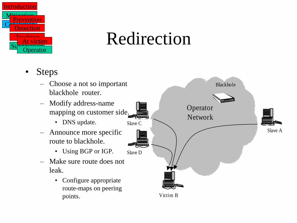
Redirection
• Steps – Choose a not so important
blackhole router.
– Modify address-name
mapping on customer side.
• DNS update.
– Announce more specific
route to blackhole.
• Using BGP or IGP.
– Make sure route does not
leak.
• Configure appropriate
route-maps on peering
points.
Operator
Network
Slave A
Slave C
Slave D
Victim B
Blackhole
Introduction
Mitigation
Conclusion Prevention
Detection
Tracking
Suppression At victim
Operator

Redirection
Operator
Network
Slave A
Slave C
Slave D
Victim B
Blackhole
• Steps – Choose a not so important
blackhole router.
– Modify address-name
mapping on customer side.
• DNS update.
– Announce more specific
route to blackhole.
• Using BGP or IGP.
– Make sure route does not
leak.
• Configure appropriate
route-maps on peering
points.
Introduction
Mitigation
Conclusion Prevention
Detection
Tracking
Suppression At victim
Operator

Other routing based techniques

Dropping/Rate limiting
• Access Control lists
– Set of conditions carrying on packet headers values.
– Action (permit/drop).
• Rate limiting
– Use ACL to specify traffic. Actions more elaborate (drop, mark, permit).
– Token Bucket (Burst Size, Mean Rate) to decide if flow is too aggressive.
– No buffers involved.
– Can be distributed using BGP.
Introduction
Mitigation
Conclusion Prevention
Detection
Tracking
Suppression At victim
Operator

Existing products
• Usually combine several mitigation phases.
• Distributed in nature.
• Some are used by network operators
– Eg: AT&T (Riverhead), Qwest (Arbor), TELUS (Arbor).
– Some operators develop in house products (eg: Sprint, France Telecom).
• Main companies:
– Riverhead networks (now bought by Cisco system).
– Arbor networks.
– Mazu networks.
– Many others.
• Often funded/spin offs of big router companies (Cisco/Juniper).
Introduction
Mitigation
Conclusion

Existing products
• Riverhead networks (bought by Cisco).
– Currently named Cisco Anomaly Guard/Anomaly Detector Modules.
Introduction
Mitigation
Monitors copy of traffic
Builds traffic Profiles
Detects changes in traffic profile
Alerts RG when attack is detected
Monitors traffic (BGP)
In line
• anti-spoofing,
• anomaly recognition,
• protocol analysis,
• rate limiting
Conclusion
Cisco Cisco

Existing products
• Sprint cleaning center (Agarwal &al., Sprint lab TR, 2004)
Introduction
Mitigation
Conclusion

Mitigations means
Source: Craig Labovitz, Bots, DDoS and Ground Truth. NANOG 50, 2010.
• From DDoS protection devices manufacturer.
Introduction
Mitigation
Conclusion

DDoS mitigation as a service
• Prolexic, akamai, verisign, …
– Once attack is detected.
– Redirect traffic to their servers using either
• Modifying DNS mapping
• BGP routing changes
– Then similar to service provided by operator/self.
• How much better than your operator can it be ?
– Delay in route propagation.
– Triangle routing.
– But ability to divert traffic closer to attackers.
Introduction
Mitigation
Conclusion

Final words
• Will we see DoS mitigation measures implemented in routers?
– Technical perspective:
• A lot of tools are already there.
– ACLs, Netflow, NBar, QoS services, uRPF ...
• Most mitigation schemes make use of them.
• But mitigators also use some more complex tools:
– Pattern matching, stateful filtering, protocol parsing, normalisation, packet
marking …
Introduction
Mitigation
Conclusion

Final words
• Will we see DoS mitigation measures implemented in routers?
– Technical perspective:
Introduction
Mitigation
Conclusion
0
200
400
600
800
1000
1200
2002 2004 2006 2008 2010 2012
Internet traffic x2/yr
Router capacity x2.2/18 months
5x
Source:
Mckeown, HPSR 2002