d.o.o. user manual for explosion …tepex.hr/wp-content/uploads/2017/08/upute-za... · model code...
TRANSCRIPT

1
d.o.o.
10090 Zagreb, Medarska 69
e-mail: [email protected]
USER MANUAL FOR EXPLOSION PROTECTED CONTROL
UNITS TYPE SKX 12, SKX 13, SKX 14, SKX 15
No: TEPEx.RS.025 Rev : 04 Date: 03.2017.
MANUFACTURER
TEP Ex d.o.o. , Medarska 69, HR-10090 Zagreb T 00385 49 222900, F 00385 49 426450 e-mail: tepextepex.hr, www.tepex.hr
PURPOSE
Explosion protected control units type SKX 12 - SKX 15 are intended for use in control, distribution and signaling circuits
in areas where an explosive gas and/or dust atmosphere may be present, respectively in hazardous areas 1, 2, 21, 22 in
accordance with the standards EN 60079-10-1:2009 and EN 60079-10-2:2009. DEGREE OF PROTECTION
Explosion protection is in accordance with the "General requirements" in the types of protection "Flameproof enclosure",
"Increased safety", "Intrinsic safety", "Encapsulation" and “Protection by enclosure” in accordance with standards: EN
60079-0:2012, EN 60079-1:2007, EN60079-7:2007, EN 60079-11:2012, EN 60079-18:2009, EN 60079-31:2009.
Explosion protection marking: II 2G Ex de IIC T6 Gb II 2G Ex de mb IIC T6 Gb
II 2G Ex e IIC T6 Gb II 2G Ex ia/ib IIC T6 Gb II 2D Ex tb IIIC T80C Db
Ambient temperature: -20°C ÷ +40°C or -20°C ÷ +50°C - depends of component Ithe Mechanical protection: IP 66 category 1, in accordance with EN 60529:1991/C1:1993/A1:2000
Resistance to shock: IK 08 in accordance with EN 62262:2002
Degree of protection: I (protective grounding) in accordance with EN 60947-1:2007/A1:2011
Design and construction of products are in accordance with apparatus standards EN 60947-1:2007/A1:2011, EN 60947-5-
1:2004/C1:2005/A1:2009, EN 60947-5-5:2007, EN 60204:2006/C1:2010 and all other related standards. Control units are in conformity with EU Directives: ATEX Directive 94/9 EC, LV Directive 2006/95/EC, EMC Directive
2004/108 EC, RoHS Directive 2002/95/EC. Control units are designed, produced and tested in conformity with the Quality management systems in accordance with
EN ISO 9001:2008 and EN ISO/IEC 80079-34:2011.
TECHNICAL DATA
Rated insulation voltage Ui : - 630 V AC
(type with mantle terminals type SL Ui = 400V AC) Rated operational voltage Ue : - depends on the built-in components
Conventional enclosed component thermal current Ithe : - 16 A max. for ambient temperature -20°C ÷ +40°C - 10 A max. for ambient temperature -20°C ÷ +50°C
PE terminals (inside of the enclosure): - 2x6 mm2 max. solid, stranded, flexible, - tightening torque 2,5 Nm
Tightening torque for build-in component terminals: - 0,8 Nm
PE/N bus bar, SKX 15 only: - max. 11 x (2x2,5 mm2) solid, stranded, flexible; Tightening torque 0,8 Nm
Cover fixing: - four cheese head screw M5x25/10-Z4 A2 ISO 7045
with plate 4,5 A2 DIN 6905,
- tightening torque 2,0 Nm
The outer cable diameter for cable gland SPU 25: - 6-10/15 mm Tightening torque for cable gland SPU 25 pressing screw: - 2,5 Nm
Tightening torque for plug SPC 25: - 4,0 Nm
Wiring: - H07V-K 1.5mm2 Enclosure: - SMC black, RAL 9005
- resistance to impact 7 J
- surface resistance < 109 Ω Gasket: - TPE 35 ShA
Dimension (without cable glands): SKX 12 : 100 x 100 x 80 mm SKX 13 : 150 x 100 x 80 mm SKX 14 : 200 x 100 x 80 mm SKX 15 : 200 x 150 x 80 mm SKX 15H: 200 x 150 x 135 mm
Mounting: SKX 12: 75 x 50 mm SKX 13: 75 x 100 mm SKX 14: 75 x 150 mm SKX 15/15H: 125 x 150 mm
2
MODEL CODE
The program consists of serial control units and control units according to customer's request.
Model code of serial control units:
Enclosure / Type no. Built-in components - Actuating components - Cable glands and plugs Control unit SKX 12/1 SLP - SPO 02/1 - SPU 25
Control unit SKX 12/2 SLP - SPO 02/2 - SPU 25
Control unit SKX 12/3 SLP - SPO 02/4 - SPU 25
Control unit SKX 12/21 SMS 03/1 - SMO 17/1 - SPU 25
Control unit SKX 12/22 SMS 03/8 - SMO 17/2 - SPU 25
Control unit SKX 12/23 SMS 03/6 - SMO 17/4 - SPU 25
Control unit SKX 12/31 PBT 01 - GHG 410 1906 R0005 - SPU 25
Control unit SKX 12/32 PBT 01 - SPO 01/1 - SPU 25
Control unit SKX 12/33 PBT 01 - SPO 01/2 - SPU 25
Control unit SKX 12/34 PBT 01 - GHG 410 1905 R0005 - SPU 25
Control unit SKX 12/35 PBT 01 - GHG 410 1906 R0005 with protector - 2xGHG 960 1955 R0002
Control unit SKX 12/36 PBT 011 - GHG 410 1906 R0005 - 2xGHG 960 1955 R0002 Control unit SKX 12/37 GHG 4101901 R0193 - GHG 410 1944 R0010 - SPU 25 Control unit SKX 12/62 5x4 mm2 EURO 4/35 grey on rail TH 35-7,5 - 2x SPU 25 Control unit SKX 12/63 5x4 mm2 EURO 4/35 blue on rail TH 35-7,5 - 2x SPU 25 blue
Control unit SKX 13/1 2xPBT 01 - SPO 01/1 - SPO 01/2 - SPU 25
Control unit SKX 13/11 PBT 01 - SPO 01/1 - SLP - SPO 02/2 - SPU 25
Control unit SKX 13/21 SL8 - 6xSPU 25
Control unit SKX 13/71 GHG 23. ...R.... (Ex 23 4 024) - SMO 17/2 - SPU 25
Control unit SKX 13/72 GHG 23. ...R.... (Ex 23 8 067) - SMO 17/1 - SPU 25
Control unit SKX 13/10 SMS 03/1 - SMO 17/1 - SPU 25
Control unit SKX 13/20 SMS 03/4 - SMO 17/2 - SPU 25
Control unit SKX 13/30 SMS 03/5 - SMO 17/2 - SPU 25
Control unit SKX 13/40 SMS 03/6 - SMO 17/2 - SPU 25
Control unit SKX 13/60 SMS 03/3 - SMO 17/3 - SPU 25
Control unit SKX 13/70 SMS 03/2 - SMO 17/1 - SPU 25
Control unit SKX 13/80 SMS 03/7 - SMO 17/1 - SPU 25
Control unit SKX 13/100 SMS 03/8 - SMO 17/5 - SPU 25
Control unit SKX 13/110 SMS 03/9 - SMO 17/1 - SPU 25
Control unit SKX 13/120 SMS 03/11 - SMO 17/2 - SPU 25
Control unit SKX 14/1 2xPBT 01 - SPO 01/1 - SPO 01/2 - SLP - SPO 02/2 - SPU 25
Control unit SKX 14/11 3xPBT 01 - SPO 01/1 - SPO 01/2 - SPO 01/3 - SPU 25
Control unit SKX 14/21 SL 8 - 8xSPU 25
Control unit SKX 14/22 3xSLP - SPO 02/1 - SPO 02/2 - SPO 02/3 - SPU 25
Control unit SKX 14/31 3xPBT 01 - SPO 01/1 - SPO 01/2 - GHG 410 1906 R0005 - SPU 25
Control unit SKX15/1 2xPBT 01- SPO 01/1 - SPO 01/2 - 2xSLP - SPO 02/1 - SPO 02/2 - 2xSPU 25 Control unit SKX15/11-11 2xPBT 01 - SPO 01/1 - SPO 01/2 - AM 72 100/1 A - 2xSPU 25 Control unit SKX15/11-12 2xPBT 01 - SPO 01/1 - SPO 01/2 - AM 72 50/1 A - 2xSPU 25 Control unit SKX15/11-21 2xPBT 01 - SPO 01/1 - SPO 01/2 - AM 72 100/5 A - 2xSPU 25 Control unit SKX15/11-22 2xPBT 01 - SPO 01/1 - SPO 01/2 - AM 72 50/1 A -2xSPU 25 Control unit SKX15/21-11 GHG 23. ...R.... (Ex 23 8 067) - SMO 17/1 - AM 72 100/1 A - 2xSPU 25
Control unit SKX15/21-12 GHG 23. ...R.... (Ex 23 8 067) - SMO 17/1 - AM 72 50/1 A - 2xSPU 25
Control unit SKX15/21-21 GHG 23. ...R.... (Ex 23 8 067) - SMO 17/1 - AM 72 100/5 A - 2xSPU 25
Control unit SKX15/21-22 GHG 23. ...R.... (Ex 23 8 067) - SMO 17/1 - AM 72 50/5 A - 2xSPU 25
Control unit SKX15/34 4xPBT/1 - 2xSPO 01/1 - 2xSPO 01/2 - 2xSPU 25 Control unit SKX15/41 SMS 03/1 - 2xCTS16U - 2xSPU 25 Control unit SKX15/50 SMS 03/12 - SMO 17/2 - SPU 25 Control unit SKX15/90 SMS 03/10 - SMO 17/3 - SPU 25 Control unit SKX15/51 SMS 03/9 - SMO 17/1 - 2xPBT/1 - SPO 01/1 - SPO01/2- 2xSPU 25
Control unit SKX15/61 GHG 23. ...R.... (Ex 23 4 024) - SMO 17/2 - 5xCTS4UN - SPU 25
Control unit SKX15/62 GHG 23. ...R.... (Ex 23 8 067) - SMO 17/1 - 5xCTS4UN - SPU 25
Control unit SKX15/65 4xSL5 - 8xSPU 25
Control unit according to customer’s request is marked with standard model code - SKX 12, SKX13, SKX 14, SKX 15
and MSRU number. MSRU number represents the factory serial number. For example SKX 15/MSRU 1234.12 Control unit, as a single unit formed of more enclosures, are marked with standard model code of each used enclosure -
SKX 12, SKX13, SKX 14, SKX 15 and MSRU number. MSRU number represents the factory serial number. For example SKX 14-15/MSRU 1235.13

3
81
100
150
75
100
100
200
80
152
75
150200
80
135
152
126
CONTROL UNIT COMPONENTS Enclosures (without cable glands):
SKX 12/ . . SKX 13/ . .
SKX 14/ . . SKX 15/ . . , SKX 15 H/ . .
Actuator and indicator: Type Technical data Mounting Review
SMO 17/.
SWITCH ACTUATOR
Explosion protection: II 2G Ex e IIC Gb II 2D Ex tb IIIC Db
32±0,5
23±0,2
5
OTVOR U STIJNCI POKLOPCA
I0 I II I 0 II
I
0
III
II
I II III
1 2
3
4
1 2
3
45
1 2
3
456
1 2
3
SMO 17/1 SMO 17/2 SMO 17/3 SMO 17/4
SMO 17/5 SMO 17/6 SMO 17/7 SMO 17/8 SMO 17/9
100
100
80
75
50

4
SAM 72
FRONT ELEMENT OF MEASURING INSTRUMENTS
Explosion protection: II 2G Ex e IIC Gb II 2D Ex tb IIIC Db
64,5±0,1
56
+0
,5-0
,2
3,5
SPO 01/.
PUSHBUTTON ACTUATOR
Explosion protection:
II 2G Ex e IIC Gb II 2D Ex tb IIIC Db
2,8
16
30
+0,20
+0,20
+0
,20
SPO 02/.
SIGNAL LAMP FRONT ELEMENT
Explosion protection:
II 2G Ex e IIC Gb,II 2D Ex tb IIIC Db
2,8
16
30
+0,20
+0,20
+0
,20
GHG 410 1904
R0012
KEY-OPERATED PUSHBUTTON ACTUATOR
Explosion protection: II 2G Ex e II II 2D Ex tD A21 IP66
2,8
16
30
+0,20
+0,20
+0
,20
GHG 410 1905
R0005
MUSHROOM-HEAD PUSHBUTTON
ACTUATOR (EMERGENCY-STOP)
Explosion protection:
II 2G Ex e II II 2D Ex tD A21 IP66
2,8
16
30
+0,20
+0,20
+0
,20
GHG 410 1906
R0005
KEY-OPERATED MUSHROOM-
HAED PUSHBUTTON ACTUATOR (EMERGENCY-STOP)
Explosion protection: II 2G Ex e II II 2D Ex tD A21 IP66
2,8
16
30
+0,20
+0,20
+0
,20
GHG 410 1944
R0010
POTENTIOMETER ACTUATOR
Explosion protection:
II 2G Ex e II II 2D Ex tD A21 IP66
2,8
16
30
+0,20
+0,20
+0
,20
SPU 25
GHG
96092...P...
Cable gland ISO 25 SPU 25
Explosion protection:
II 2D Ex e IIC Gb II 2D Ex tb IIIC Db
Cable gland ISO 16 – ISO 40
Explosion protection: II 2G Ex e II II 2D Ex tD A21 IP66
25,5+0,2-0,4
Type SPO 01/.
SPO 01/01 0
SPO 01/02 I
SPO 01/03 II
SPO 01/04 RED
SPO 01/05 GREEN
SPO 01/06 WHITE
SPO 01/07 START
SPO 01/08 STOP
SPO 01/09 ON
SPO 01/10 OFF
Type SPO 02/.
SPO 02/01 RED
SPO 02/02 GREEN
SPO 02/03 YELLOW
SPO 02/04 TRANSPARENT

5
FGA1 – FGA4
CABLE GLAND ISO 16 - ISO 40
Explosion protection:
II 2G Ex e II II 2D Ex tD A21 IP66/67 A,5
+0,2-0,4
A
SPC 25
GHG 960 663 P...
PLUG ISO 25 SPC 25 Explosion protection: II 2D Ex e IIC Gb II 2D Ex tb IIIC Db
PLUG ISO 16 – ISO 40 GHG 960 663 P...
Explosion protection:
II 2G Ex e II II 2D Ex tD A21 IP66
25,5+0,2-0,4
Build-in components:
Type Technical data Sheme Review
SMS 03/.
CONTROL SWITCH
Explosion protection: Rated insulation voltage: 690 V Rated thermal current: 16 A
Switching capacity AC 23:
690 V/8 A Switching capacity AC 3:
380 V/10 A Switching capacity DC 21: 60 V/10 A 110 V/1,85 A 220 V/0,6 A Terminals: 2 x 1,0 - 2,5mm2
SMS 03/1
SMS 03/4
SMS 03/5
SMS 03/6
SMS 03/12
SMS 03/3
SMS 03/2
SMS 03/7
SMS 03/10
SMS 03/8
SMS 03/9
SMS 03/11

6
GHG 23. ... R....
CONTROL SWITCH
Explosion protection: II 2G Ex de IIC
Rated insulation voltage: 690 V Rated thermal current: 10 A Switching capacity AC 11: 230 V/10 A 500 V/6 A Switching capacity DC 11: 24 V/2 A 230 V/0,4 A Terminals: 2 x 1,0 - 2,5mm2
-
060
062
065
061
063
067
011
034
037
049
023
019
033
024
PBT/ .
PTB/ . G
PUSHBUTTON
Explosion protection: II 2G Ex d e IIC Gb I M2 Ex d e I Mb
Rated insulation voltage: 690 V
Rated thermal current: 16 A Switching capacity AC 15:
250 V/6 A 500 V/4 A Switching capacity DC 13: 24 V/6 A 60 V/0,8 A 110 V/0,5 A Terminals: 2 x 1,0 - 2,5mm2 PTB/ . G - gold plated contacts
For voltages up to 60 V and currents 1,0
mA to 200 mA
13 21
14 22
PBT/01
13 23
14 24
PBT/02
11 21
12 22
PBT/03
SLP
SIGNAL LAMP
Explosion protection:
II 2G Ex d e IIC Gb I M2 Ex d e I Mb
Rated insulation voltage: 690 V
Rated voltage: 12 to 250 V AC/DC Rated current: 12 to 2,5 mA Terminals: 2 x 1,0 -2,5 mm2
X1 X2
7
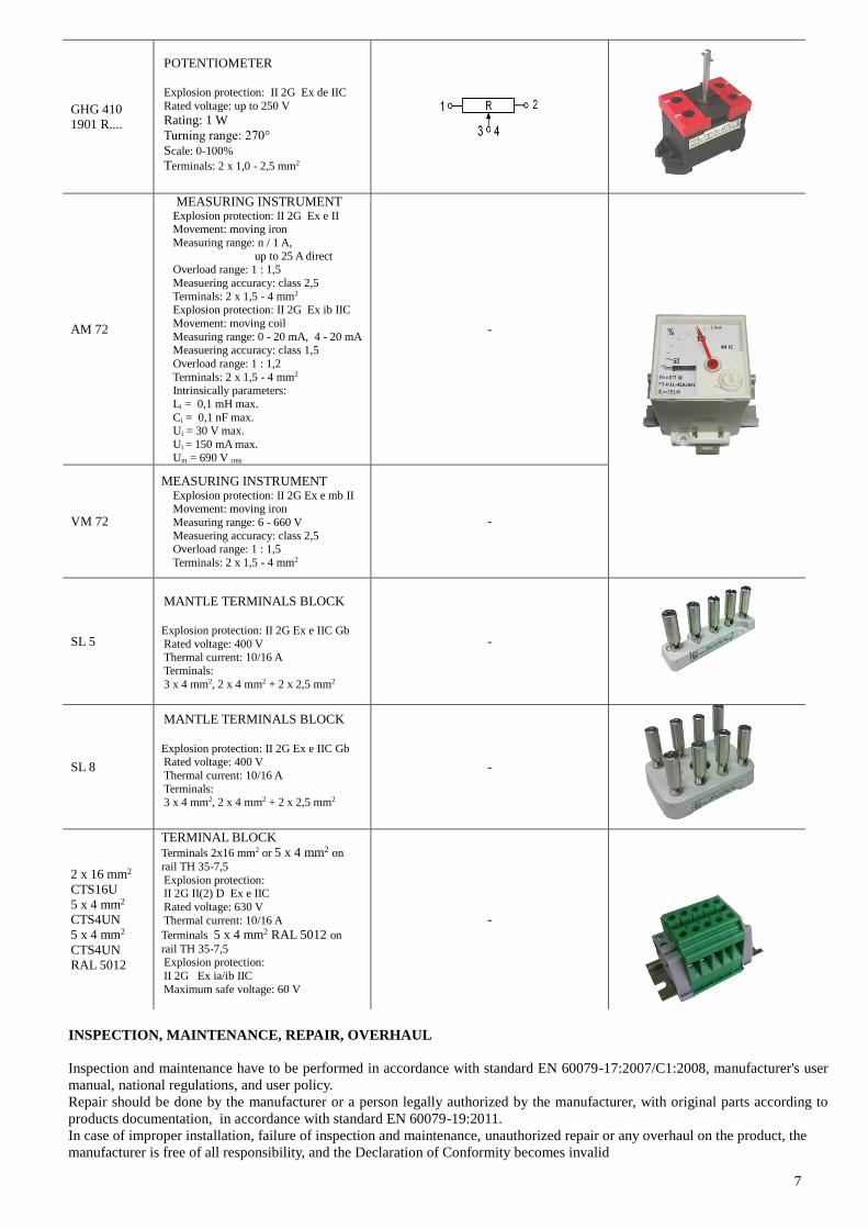
GHG 410
1901 R....
POTENTIOMETER Explosion protection: II 2G Ex de IIC Rated voltage: up to 250 V Rating: 1 W
Turning range: 270°
Scale: 0-100% Terminals: 2 x 1,0 - 2,5 mm2
AM 72
MEASURING INSTRUMENT Explosion protection: II 2G Ex e II Movement: moving iron
Measuring range: n / 1 A, up to 25 A direct Overload range: 1 : 1,5
Measuering accuracy: class 2,5
Terminals: 2 x 1,5 - 4 mm2 Explosion protection: II 2G Ex ib IIC Movement: moving coil
Measuring range: 0 - 20 mA, 4 - 20 mA Measuering accuracy: class 1,5
Overload range: 1 : 1,2
Terminals: 2 x 1,5 - 4 mm2 Intrinsically parameters:
Li = 0,1 mH max. Ci = 0,1 nF max. Ui = 30 V max. Ui = 150 mA max. Um = 690 V rms
-
VM 72
MEASURING INSTRUMENT Explosion protection: II 2G Ex e mb II Movement: moving iron
Measuring range: 6 - 660 V
Measuering accuracy: class 2,5 Overload range: 1 : 1,5 Terminals: 2 x 1,5 - 4 mm2
-
SL 5
MANTLE TERMINALS BLOCK
Explosion protection: II 2G Ex e IIC Gb Rated voltage: 400 V Thermal current: 10/16 A
Terminals:
3 x 4 mm2, 2 x 4 mm2 + 2 x 2,5 mm2
-
SL 8
MANTLE TERMINALS BLOCK
Explosion protection: II 2G Ex e IIC Gb Rated voltage: 400 V
Thermal current: 10/16 A
Terminals: 3 x 4 mm2, 2 x 4 mm2 + 2 x 2,5 mm2
-
2 x 16 mm2 CTS16U
5 x 4 mm2 CTS4UN
5 x 4 mm2 CTS4UN
RAL 5012
TERMINAL BLOCK
Terminals 2x16 mm2 or 5 x 4 mm2 on
rail TH 35-7,5 Explosion protection: II 2G II(2) D Ex e IIC Rated voltage: 630 V Thermal current: 10/16 A Terminals 5 x 4 mm2 RAL 5012 on
rail TH 35-7,5 Explosion protection:
II 2G Ex ia/ib IIC Maximum safe voltage: 60 V
-
INSPECTION, MAINTENANCE, REPAIR, OVERHAUL
Inspection and maintenance have to be performed in accordance with standard EN 60079-17:2007/C1:2008, manufacturer's user
manual, national regulations, and user policy. Repair should be done by the manufacturer or a person legally authorized by the manufacturer, with original parts according to
products documentation, in accordance with standard EN 60079-19:2011.
In case of improper installation, failure of inspection and maintenance, unauthorized repair or any overhaul on the product, the
manufacturer is free of all responsibility, and the Declaration of Conformity becomes invalid

8
MOUNTING:
SPARE PARTS (according component specification)
1. Enclosure and cover SKX 12-15 with cover screw and PE
terminal body
2. Cable glands and plugs; according to specification 3. Cover gasket SKX . .
4. Build-in components; according to specification 5. Actuators and indicators; according to specification 6. Terminal PE
MARKING
Explosion protected control units type SKX 12 - SKX 15 are labeled internal and external:
1) Model code 2) Rated voltage Ue - depends on the built-in components 3) Thermal current Ithe - depends on the built-in components and ambient tempertature 4) Type examination certificate number 5) Factory number 6) Date, month/year Warning label:
SKX . ./ . . . . . . V . . . A IP66
CESI 12 ATEX ... MA/MR ....... DATE ......
HR - 10090 Zagreb
II 2G Ex de IIC T6 Gb
II 2D Ex t IIIC T80°C Db
0722
94,5
42
WARNINGDO NOT OPEN WHEN ENERGIZED
OR
1) 2) 3)
4) 5) 6)
II 2G Ex de mb IIC T6 Gb
II 2D Ex t IIIC T80°C Db
II 2G Ex e II T6 Gb
II 2D Ex t IIIC T80°C Db
II 2G Ex ia/ib IIC T6 Ga/Gb
Control units with measuring instruments type AM72, VM72
Control units with terminals type SL5, SL8, TH 35 5x4mm2
Control units with Ex i terminals 5x4mm2
Kućište dimenzije
X[mm] Y[mm]
SKX 12 75 50
SKX 13 100 75
SKX 14 152 75
SKX 15/15H 152 126