document resume - eric · document resume. ed 128 624. ce 007 944. ... exercises assigned to...
TRANSCRIPT
DOCUMENT RESUME
ED 128 624 CE 007 944
AUTHOR Emerly, Robert J.; And OthersTITLE Machine Shop Practice. "rade and Industrial Education
Course of Study.INSTITUTION Pennsylvania State Dept. of Education, Harrisburg. .
Bureau of Vocational Education.; Pennsylvania StateUniv., University Park. Dept. r VocationalEducation.
PUB DATE 73NOTE 289p.
EDRS PRICEDESCRIPTORS
ABSTRACT
MF-$0.83 HC-$15.39 Plus Postage.*Curriculum Guides; *Learning Actil,ities; *MachineTools; *Mechanics (Process) ; Secondary Education;*Shop Curriculum; *Teaching Guides; TechnicalEducation; Trade and Industrial Education; VocationalEducation
Designed for secondary school students who areinterested in becoming machinists, this beginning course guide inmachine shop practice is organized into'the following sections', (1)
Introduction, (2) instructional plan, (3) educational philosophy, (4)
specific course objectives, (5) course outline, (6) job sheets, and(7) operation sheets. The course outline calls for 470 hours ofapplicatory jobs to be completed by students; 35 hours of skilldevelopment lessons and 35 hours of information lessons are to bepresented by the instructor. For each of the 73 applicatory jobs, ajob sheet is included that tells the student what to do in performingthe job. The job sheet contains a photograph and scale drawing of thetool, equipment list, list of tools needed, safety precautions, andprocedures. Operation sheets supplement the job sheets and tell thestudent how to perform the operations necessary to complete theassigned jobs. Keyed to the skill development lessons, each operatf.onsheet lists the tools and equipment, and procedure for a specificoperation, along with an introductory explanation. The eight unitscovered are: Lathe operation, power saw operation, bench work,milling machine operation, shaper operation, drilling machineoperation, surface grinder operation, and heat treatment. Suggestedinformation lesson titles are listed, but information sheets andassiynment sheets are to be prepared by the instructor.(Author/RG)
***********************************************************************Documents acquired by ERIC include many informal unpublished
* materials not available from other sources. ERIC makes every effort ** to obtain the best copy available. Nevertheless, items of marginal *
* reproduci;:ility are often encountered and this affects the quality *
* of the microfiche and hardcopy reproductions ERIC makes available* via the ERIC Document Reproduction Service (EDRS) . EDRS is not* responsible for the quality of the original document. 1:eproductions ** supplied by EDPS are the best that can be made from the original.***********************************************************************

c\J
00Cr-4
TRADE AND INDUSTRIAL EDUCATION
COURSE OF STUDY
FOR
MACHINE SHOP PRACTICE
COMPILED BY
Robert J. EmerlyClearfield County Area Vocational-Technical School
M. William GolderColumbia-Montour Area Vocational-Technical School
Charles R. SkoviraCarlisle Area Senior High School
IN COOPERATION WITH
Department of Vocational EducationCollege of EducationThe Pennsylvania State University
AND
Department of EducationBureau of Vocational EducationHarrisburg, Pennsylvania
411,1
L) 1973
u s DEPARTMENTOF HEAL TH.EDUCATION
3 WELFARENATIONAL INSTITUTEOFEDUCATION
THts DOCUMENTHAS SEEN
REPRO-OUCEL. EXACTL
Y AS RECEIVEDFROM
THE PERSONOR ORGANIZATIONORIGIN-A TING IT
POINTS OFVIEW 017 OPINiONS
STATEDDO NOT NECESSARQ
Y PEPPESEN T OFFICIALNATIONAL
INS ri TUTEOF
EOUCATIONPOSITION
OP POL ICY

Commonwealth of PennsylvaniaMilton J. Shapp, Governor
DeparIlent of EducationJohn C. Pittenger, Secretary
Office of Basic EducationDonald M. Carroll, Jr., CommissionerHarry K. Gerlach, Deputy Commissioner
Bureau of Vocational EducationJohn W. Struck, Director
Vocational Program Development DivisionWilliam P. Hartman, Chief
Trade and INdustrial EducationRobert jacoby, Senior Program Specialist
Pennsylvania Department of EducationBox 911
Harrisburg, Pa. )7126

PREFACE
In recent years the finest of vocational education building
facilities have been planned and constructed in the Commonwealth
of Pennsylvania, and in these buildings the best available equip-
ment has been installed. Equal attention must now be directed to
provide the vocational teacher with the basic tools for quality
instruction.
This basic course of study is intended to be used by the
teacher as a teaching guide. .The information provides the essen-
tials of the occupation, insuring that the students who success-
fully complete the course will have sufficient competencies for
entry employment, and ample orientation for growth and advancement
ir the labor market. The teacher who uses this course of study
will want to modify and supplement the material to meet the
specific needs of students and the industrial community.
William A. Williams, HeadDepartment of Vocational Industrial EducationThe Pennsylvania State UniversityUniversity Park, Pennsylvania 16802
January 1973

TABLE OF CONTENTS
Section Page
1. INTRODUCTORY STATEMENT 1
2. PLAN OF INSTRUCTIONAL PRACTICES 2
3. STATEMENT OF EDUCATIONAL PHILOSOPHY 4
4. SPECIFIC COURSE OBJECTIVES 5
5. COURSE OUTLINF 6
A. Applicatory Jobs 7
B. Skill Development and Information Lessons 10
6. JOB SHEETS 15
7. OPERATION SHEETS 259
8. INFORMATION SHEETS AND ASSIGWENT SHEETS 431

Section 1
INTRODUCTORY STATEMENT
This course is intended for secondary school students who areinterested in securing employment as machinists. It is designed as abeginning course in machine shop practice, and would usually be offeredto tenth grade students.
The course is designed to give the students an-opportunity to:
1. develop the necessary skills required to perform thetasks of the machinist,
2. acquire the related information necessary to exercisegood judgment in carrying out the construction,maintenance, servicing and repairing operationsrequired of the machinist,
3. develop an appreciation of good workmanship, safety,and correct work habits and attitudes.
This course will be conducted as a part of the vocationaleducation program of a school district, and will be administeredthrough the facilities of the local vocational program as a tradepreparatory course.

Section 2
PLAN OF INSTRUCTIONAL PRACTICES
Introduction
In presenting this course for the training of machinists, certaininstructional practices will be employed. These practices are presented
to insure the most effective instructional program. From time to time,
some of the practices recommended may be altered to meet requiredchanges in instructional situations and to meet changes in the techno-logical phases of the occupation.
Teaching Methods
To achieve the desired objectives of this course, the followingteaching methods will be employed:
1. Demonstrations--accurate portrayals of procedures or
manipulative operations. In the process of teaching,demonstrations show how things are done, and showthew in such a way that students will learn theprocedures and operations.
2. Class Discussions--a method of teaching in which themembers of a class and a teacher.takepart, directedand controlled by the teacher toward a predeterminedgoal, with most of the deas contributed by the class.This method is used in the presentation of relatedinformation, reports of field trips, and classorganizational problems.
3. Shop Talks--an informal lecture used by the teacher in ashop atmosphere for the presentation of related technical
information. Shop talks should be relatively short--notmore than twenty minutes.
Teaching Aids
To provide a more effective presentation of skills and relatedtechnical information, the following types of teaching aids will be
used:
1. Reference books
2. Job sheets, operation sheets, information sheetsand assignment sheets
3. Charts, graphs, prints, posters
4. Strip film and slide film projectors
- 2

5. Overhead projectors
6. Motion picture projectors
7. Models and mock-ups
8. Manufacturers literature
Vehicles of Instruction
The application phase of this course will consist of jobs andexercises assigned to students for completion. To provide forindividual differences, job sheets, operation sheets, informationsheets and assignment sheets will be used. Unusually capable studentswill be encouraged to work on special jobs of an advanced nature. Each
student will be permitted to progress at his own natural learning rate,with special attention given to the slow learner.
Average Size of Class
This course is designed for a class of not more than twenty-fivestudents per shop instructor.
Physical Facilities Required
A shop room with an area of not less than 2,700 3,000 square
feet will be required. In addition, a small classroom of 425 squarefeet, to accommodate twenty-five students, will be provided.
3
8

Section 3
STATEMENT OF EDUCATIONAL PHILOSOPHY
Educational Philosophy of the School System
'-. The primary function of the educational program in any community isthe development of the individual citizen, youth or adult, in all hiscapacities, so that he will be a good member of the community and of thelarger democracy of which he is a part.
Basic Philosophy of Vocational Education
Vocational education, as an integral part of the total educationprogram of the community, makes a contribution toward the development ofgood citizens--including their health, social, civic, cultural and eco-nomic interests. Its chief purpose is to prepare individuals for gainfulemployment through the development of skills, knowledges, understandings,attitudes, work habits, appreciations, leadership qualities and citizenshipqualities.
Basic Philosophy of Vocational Industrial Education
Vocational industrial education is a phase of vocational educationthat provides instruction and experience for the purpose of fittingpersons for gainful employment in trade, technical and industrialpursuits. The major objectives of this program are as follows:
I. To provide instruction of a preparatory type in thedevelopment of basic manipulaLive skills, safety judgment,technical knowledge, and related technical information forthe purpose of fitting persons for gainful employment.
2. To provide instruction of an extension type for the fur-ther development of performance skills, technicalknowledge, related technical information, safety, andjob judgment for persons already employed.
Instruction in vocational industrial education is provided forfour general groups:
1. Journeymen and other industrial workers who needextension instruction in industrial subjects.
2. Apprentices and other learners who need instructionin trade, technical and industrial subjects.
3. Out-of-school youth who need training and experi-ences, coordinated by public school authorities, tofit them for gainful employment.
4. In-school youth who have selected an occupation andwho need training for entrance into a trade,technical or industrial pursuit.
This course for the training of machinists falls under the fourthcategory.
-4-
9

Section 4
SPECIFIC COURSE OBJECTIVES
Objectives
1. To develpp specific skills 1.
and related information 2.
associated with the occu- 3.
pation of machinist
2. To develop an understanding 1.
of labor and management 2.
3.
3. To develop good habits of 1.
work
4. develop occupationalsafety habits and under-standings
2.
3.
4.
5.
Activities to Achieve Objectives
Series of individual jobsSeries of practice exercisesUse of job sheets, operation sheets,information sheets and assignmentsheets for individual students
Assign reading in trade magazinesArrange for talks by representa-tives of labor and managementSchedule discussions on problemsdealing with
a. Labor unionsb. Responsibilities of management
Provide specific standards foreach job or exerciseMaintain a clean, well-organizedshop area and classroom which areconducive to effective learningDiscuss with students the import-ance of good work habits and theirrelationship to industrial practiceand shop advancementEvaluate students' work objectivelyProvide a means for students to plantheir work accurately and methodically
1. Display safety posters2. Provide safety devices for all
hazardous work activity3. Demonstrate correct safety practice
whenever appropriate4. Show motion picture on effective
safety practices
5. To develop the ability 1.
to work cooperativelywith fellow workers 2.
6. To stimulate thedevelopment of leader-ship qualities
3.
4.
2.
- 5
1 0
Set up a maximum of class andgroup projectsEncourage students to seek helpfrom each otherProvide student planning committeesAssign the more advanced studentsto assist students needing help
Provide opportunity for studentsto plan their assigned work jobsand write their own job sheetsProvide a plan for students toappraise their own work

Section 5
COURSE OUTLINE
The course is developed in the following areas with the appropriatetime distribution:
A. Applicatory Jobs - completed by students
B. Skill Development Lessons - presented byinstructor
C. Information Lessons - presented by instructor
- 6
11.
470 hours
35 hours
35 hours

A. APPLICATORY JOBS
With a total of approximately 470 hours allowed for applicatoryjobs, an average of 7.5 hours would therefore be available for each ofthe following: (these are job titles only--the numbers preceding eachtitle correspond with the identifying numbers found on the job sheetsincluded in Section 6 of this course of study).
J-1-10-1
J-2-10-2
J-3-10-3
J-4-10-4
J-5-10-5
J-6-10-6
J-7-10
J-7-10-7
J-7-10-8
J-7-10-9
J-7-10-10
J-8-10
J-8-10-11
J-8-10-12
J-8-10-13
J-8-10-14
J-9-10-15
J-10-10
J-10-10-16
J-10-10-17
J-10-10-18
J-10-10-19
J-10-10-20
Drill Drift
Tool Post Wrench
Cross-peen Hammer
Idler Shaft
Stud Bolt
Can Punch
Depth Gauge
Depth Gauge--Base
Depth Gauge--Handle
Depth Gauge--Screw
Depth Gauge--Rod
C-Clamp
C-Clamp--Body
C-Clamp--Screw
C-Clamp--Screw Cap
C-Clamp--Handle
Drill Grinding Gauge
Parallel Clamp
Parallel Clamp--Threaded Jaw
Parallel Clamp--Loose Jaw
Parallel Clamp--Straight Clip
Parallel Clamp--Adjusting Screw
Parallel Clamp--Clamping Screw
- 7 -
1 2

J-11-10 Tap Wrench
J-11-10-21 Tap Wrench--Handles
J-11-10-22 Tap Wrench--Screws
J-12-10-23 Punch Set
J-13-10-24 Cold Chisel
J-14-10 Ball Peen Hammer
J-14-10-25 Ball Peen Hammer--Head
J-14-10-26 Ball Peen Hammer--Handle
J-14-10-27 Ball Peen Hammer--Handle Plug
J-15-10 Jack Screw
JL15-10-28 Jack Screw--Base
J-15-10-29 Jack Screw--Sleeve
3-15-10-30 Jack Screw--Screw
J-15-10-31 Jack Screw--Swivel
J-16-10 Meat Tenderizer
J-16-10-32 Meat Tenderizer--Head
J-16-10-33 Meat Tenderizer--Handle
J-17-10-34 Lathe Centers
J-18-10 Scriber
J-18-10-35 Scriber--Nose
J-18-10-36 Scriber--Plug
J-18-10-37 Scriber--Point
J-18-10-38 Scriber--Body
J-19-10-39 Plumb Bob
J-20-10 Paper Punch
J-20-10-40 Paper Punch--Body
J-20-10-41 Paper Punch--Base
- 8 -
1 3

J-20-10-42
J-20-10-43
J-20-10-44
J-21-10
J-21-10-45
J-21-10-46
J-21-10-47
J-21-10-48
J-21-10-49
J-22-10
J-22-10-50
J-22-10-51
J-22-10-52
J-22-10-53
J-22-10-54
J-22-10-55
J-22-10-56
J-23-10
J-23-10-57
J-23-10-58
J-23-10-59
J-23-10-60
J-23-10-61
Paper Punch--Punch
Paper Punch--Cap
Assembly of Paper Punch
Center Finder
Center Finder--Cap
Center FinderBall
Center Finder--Point
Center FinderInsert
Center Finder--Shank
Wheel Puller
Wheel Puller--Yoke
Wheel Puller--Legs
Wheel Puller--Screw
Wheel Puller--Knobs
Wheel Puller--Handle
Wheel Puller--Leg Screws
Wheel Puller--Point
Tool Makers Vise
Tool Makers ViseBody
Tool Makers Vise--Movable Jaw
Tool Makers Vise--Sliding Plate
Tool Makers Vise--Screw
Tool Makers Vise--Hardened Jaws

SKILL DEVELOPMENT AND INFORMATION LESSONS
Approximately 35 hours of instruction time are necessary for teacherdemonstration of the Skill Development Lessons and approximately 35 hoursfor Information Lessons presented by the instructor. The numbers precedingeach title correspond to the identifying numbers of the operation sheetsand information sheets. Suggested information lesson titles are listed.Each instructor should prepare his own information lessons due to thepersonal nature of said lessons. Therefore, no information sheets areincluded as a part of this document.
B. Skill Development Lessons C. Information Lessons
Unit I -- Lathe Operation Unit I -- Lathe !.:enation
SL-1-1 Drilling Center Holes on the IL-1-1 History of the .e.the
Lathe
SL-1-2
SL-1-3
SL-1-4
SL-1-5
SL-1-6
Mounting Work Between Centers IL-1-2 Lathe Types & Construction
Facing Ends Between Centers
Turning Between Centers
Aligning Lathe Centers
IL-1-3 Types & Kinds of Workhold-ing Devices
IL-1-4 Types and Kinds of LatheAccessories
Turning Shoulders on the Lathe IL-1-5 Care of Lathes & PersonalSafety
SL-1-7 Rounding and ChamferingIL-1-6 HiTurned Edges gh Speed Single Point
Cutting ToolsSL-1-8 Turning Grooves on the
Lathe IL-1-7 Description of Speeds &Feeds on the Lathe
SL-1-9 Filing and Polishing onthe Lathe
SL-1-10 Knurling on the Lathe
SL-1-11 Threading on the Lathe
SL-1-12 Turning Angles with theCompound Rest
SL-1-13 Turning Tapers by OffsetTailstock Method
SL-1-14 Mounting Work on a Mandrel
SL-1-15 Truing Work in the LatheChuck
SL-1-16 Using Draw-in Collets
SL-1-17 Facing Chuck Work on theLathe
- 10 -
IL-1-8 Fypes of Centering Tools
IL-1-9 Description of Center Holes
IL-1-10 Description of Lathe Centers
IL-1-11 Types & Kinds of KnurlsUsed on the Lathe
IL-1-12 Common Terms Used in theMeasurement of Angles
IL-1-13 Rules for Figuring TaperTurning with TailstockOffset
IL-1-14 Rules for Figuring Tapers
IL-1-15 Description of Taper Turn-ing with Taper Attachment
1 5

B. Skill Development Lessons C. Information Lessons
SL-1-18 Drilling on the Lathe
SL-1-19 Boring on the Lathe
SL-1-20 Reaming on the Lathe
SL-1-21 Tapping on the Lathe
SL-1-22 Cutting Off Stock on theLathe
SL-1-23 Changing Feeds on the Lathe
SL-1-24 Changing Speeds on the Lathe
SL-1-25 Mounting a Lathe Chuck
SL-1-26 Grinding Lathe Tools
SL-1-27 Using Taper Attachment
IL-1-16 Depth Settings for CuttincThreads on the EngineLathe
IL-1-17 Description of the Thread-Chasing Dial
IL-1-18 Description of GraduatedCollars
IL-1-19 Description and Setting ofthe Compound Rest
Unit 2 -- Power Saw Operation Unit 2 -- Power Saw Operat
SL-2-1 Cutting Off Material IL-2-1 Types & Kinds of Power Saw
SL-2-2 Cutting to a Layout IL-2-2 Types & Kinds of Bladr,. -Fo
Power Saws
IL-2-3 Safety Precautions on PoweSaws
Unit 3 -- Bench Work Unit 3 -- Bench Work
SL-3-1 Measuring--Linear IL-3-1 Using Linear Measurement
SL-3-2 Sawing with a Hand Hacksaw IL-3-2 The Meaning of a Decimal
SL-3-3 Squaring IL-3-3 The Use and Care of Micro-meter Calipers
SL-3-4 Using Layout ToolsIL-3-4 Using the Dial Indicator
SL-3-5 Laying OutIL-3-5 Shapes of Stock
SL-3-6 FilingIL-3-6 Kinds of Metals and How
SL-3-7 Threading with Hand Dies to Identify Them
SL-3-8 Measuring - Micrometers IL-3-7 Reading a Drawing & Plan-ning Your Work
SL-3-9 Chipping
1 6
B. Skill Development C. Information Lessons
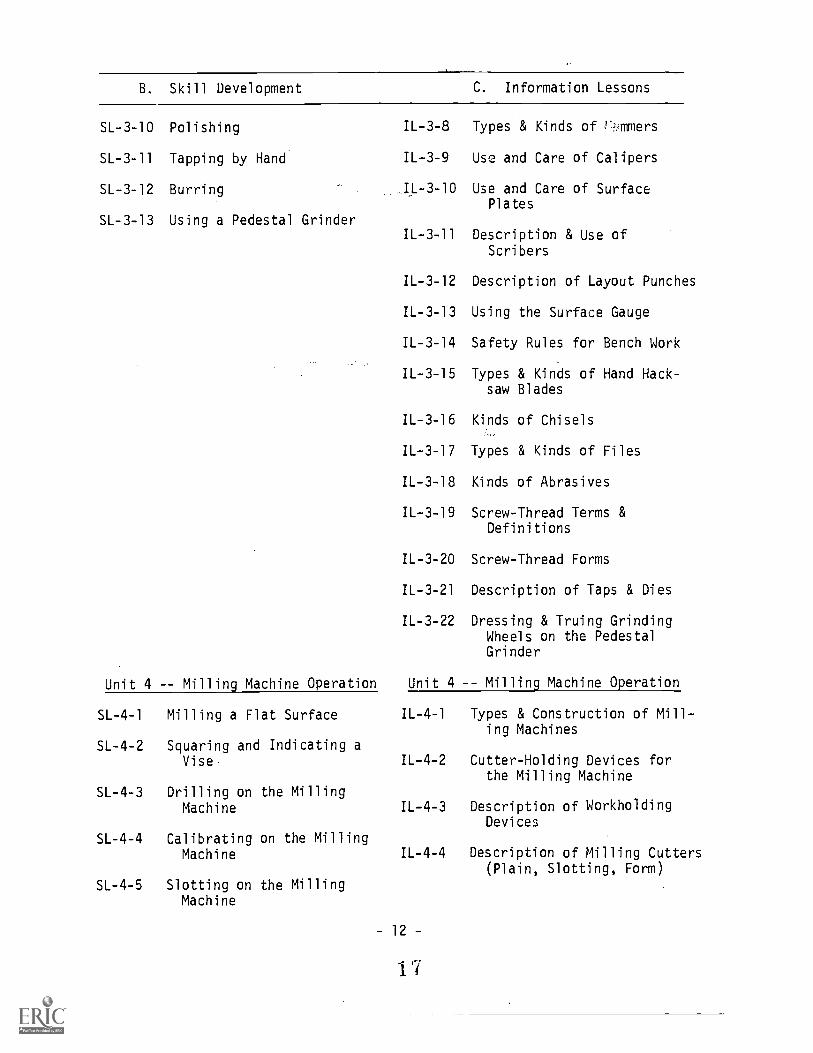
SL-3-10 Polishing IL-3-8 Types & Kinds of rmmers
SL-3-11 Tapping by Hand IL-3-9 Use and Care of Calipers
SL-3-12 Burring IL-3-10 Use and Care of SurfacePlates
SL-3-13 Using a Pedestal GrinderIL-3-11 Description & Use of
Scribers
IL-3-12 Description of Layout Punches
IL-3-13 Using the Surface Gauge
IL-3-14 Safety Rules for Bench Work
IL-3-15 Types & Kinds of Hand Hack-saw Blades
IL-3-16 Kinds of Chisels
IL-3-17 Types & Kinds of Files
IL-3-18 Kinds of Abrasives
IL-3-19 Screw-Thread Terms &Definitions
IL-3-20 Screw-Thread Forms
IL-3-21 Description of Taps & Dies
IL-3-22 Dressing & Truing GrindingWheels on the PedestalGrinder
Unit 4 -- Milling Machine Operation Unit 4 Milling Machine Operation
SL-4-1 Milling a Flat Surface IL-4-1 Types & Construction of Mill-ing Machines
SL-4-2 Squaring and Indicating aVise. IL-4-2 Cutter-Holding Devices for
the Milling Machine
SL-4-3 Drilling on the MillingMachine IL-4-3 Description of Workholding
Devices
SL-4-4 Calibrating on the MillingIL-4-4 DeMachine scription of Milling Cutters
(Plain, Slotting, Form)
SL-4-5 Slotting on the MillingMachine
12
I 7

B. Skill Development Lessons C. Information Lessons
SL-4-6
SL-4-7 Reaming on the Milling
SL-4-8 Seating a Work Piece in aVise on Milling Machine
SL-4-9 Mounting the Milling Cutter
Counterboring on the Mill-ing Machine
Machine (Vertical)
SL-4-10 Mounting a Vise on the Mill-ing Machine Table
SL-4-11 Dismounting a Vise on theMilling Machine Table
SL-4-12 Dismount a Milling Cutter
SL-4-13 Mount and D'Ismount a MillingMachine Arbor
IL-45 Description of Speeds & Feedson the Milling Machine
IL-4-6 Safety Precautions for Mill-ing Machine
Unit 5 -- Shaper Operation Unit 5 -- Shaper Operation
SL-5-1 Shaping a Horizontal IL-5-1 Construction & Types ofSurface Shapers
SL-5-2 Adjusting the Stroke andPosition of the Ram
IL-5-2 Description of Shaper Work-holding Devices
SL-5-3 Grinding Shaper Tools IL-5-3 Description of Shaper Speeds& Feeds
SL-5-4 Adjusting the Speeds & IL-5-4 Safety Precautions on theFeeds on the Shaper Shaper
Unit 6 -- brillirg Machine Unit 6 -- Drilling Machine
Operat.on. Operation
SL-6-1 Drilling on the Drill Press IL-6-1 Drill Press lypes & Con-struction
SL-6-2 Reaming on the Drill Press IL-6-2 Description of Drills &Drilling Fundamentals
SL-6-3 Countersink on theDrill Prel::
IL-6-3 Description of Speeds, Feedsand Coolant for Drilling
SL-6-4 Grinding a Drill IL-6-4 Reamers--Types and Selection
- 13 -
1 8

B. Skill Development Lessons C. Information Lessons
Unit 7 Surface GrinderOperation
SL-7-1 Using a Permanent MagnetChuck
SL-7-2 Grinding a Flat Surface
SL-7-3 Dressing the Grinding Wheel
SL-7-4 Squaring Stock on theSurface Grinder
SL-7-5 Mounting a Grinding Wheel
Unit 8 -- Heat Treatment
SL-8-1 Hardening and TemperingSteel
SL-8-2 Case-Hardening Steel
SL-8-3 Annealing Steel
IL-6-5 Types of Cutters Used onDrill Press
IL-6-6 Description of Work-holding Devices
IL-6-7 Description of Cutter-Holding Devices
IL-6-8 Safety Precautions on theDrill Press
Unit 7 -- Surface GrinderOperation
IL-7-1 Description of Work-holding Devices
IL-7-2 Grinding Wheel Construction
IL-7-3 Care & Use of GrindingWheels
IL-7-4 Dressing & TruingGrinding Wheels
IL-7-5 Safety Precautions on theSurface Grinder
Unit 8 -- Heat Treatment
IL-8-1 Description Heat-Treating Methods
IL-8-2 Types of Heat-TreatingFurnaces
IL-8-3 Description of Steeland its Alloys
IL-8-4 Kinds and Types of Hard-ness Testing Machines
IL-8-5 Table of Temperaturesand CorrespondingColors for TemperingTool Steel
- 14 -
1 9

Section 6
JOB SHEETS
Job Sheets indicate to the student what to do in performingthe varioiiTjErs assigned by the teacher. The jobs that will beused as vehicles of instruction in this course are listed inSection 5. The job sheets included in this section (Section 6)are numbered to correspond with the applicatory jobs listed inthe COURSE OUTLINE.
20
- 1 5 -

JOB SHEET
Job No. J-1-10-1 Drawing No. 1-10A1
DRILL DRIFT
EQUIPMENT: Power cutoff saw, heat treating furnace, bench vise, and drill press.
TOOLS: tongsscriberfile cardlayout dye1/4" drillprick punch
SAFETY PRECAUTIONS:
3" dividerscutting oilhand hacksawcenter punchlayout hammer6" steel rule
abrasive clothasbestos gloves82° countersink10" mill file10" flat filecase hardening compound
1. Sharp tools are safer to use than dull ones.2. Always inspect scribers, prick punches, and dividers before using them.3. Check all dimensions carefully to limit material loss.4. Operate no equipment without authority to do so.
PROCEDURE:
1. Select 1/4" by 3/4" C.R. steel.2. Cut off stock 5-1/8" long on power cutoff saw, allowing 1/8" for
squaring (refer to Operation Sheet Nos. SL-2-1 and SL-3-1).3. Remove burrs (refer to Operation Sheet No. SL-3-12).4. Layout as per print (refer to Operation Sheet Nos. SL-3-4 and
SL-3-5).5. Drill 1/4" diameter hole and countersink both sides (refer to
Operation Sheet Nos. SL-6-1, 3, and 4).6. Saw approximately 1/32" outside of layout lines (refer to Operation
Sheet No. SL-2-2).7. File piece to layout lines (refer to Operation Sheet No. SL-3-6).8. Finish file, draw file all surfaces.9. Polish with abrasive cloth (refer to Operation Sheet No. SL-3-10).
10. Case harden (refer to Operation Sheet No. SL-8-2).11. Repolish with abrasive cloth.12. Inspect as per print.
- 17 -

1-6R 16
SE
CT
ION
A A
,-iD
RIL
L- 8
2° C
SK
DP
.32
MA
TE
RIA
L- A
I SI
1018
C.R
.S.
HE
AT
TR
EA
TM
EN
T -
CA
SE
HA
RD
EN
SC
ALE
I = I
DA
TE
:12
-26-
70A
PP
RO
VE
D B
Y:
DR
AW
N B
YD
.G.H
.
RE
VIS
ED
DR
ILL
DR
IFT
SH
EE
TI O
F I
UN
LES
S O
TH
ER
WIS
E S
PE
CIF
IED
:F
RA
CT
1DN
AL
DIM
EN
SIO
NS
t1/6
4D
EC
IMA
L D
IME
NS
IDN
S.±
.005
AN
GU
LAR
DIM
EN
SIO
NS
±1
2
DR
AW
ING
NU
MB
ER
I- IO
AI
PR
EP
AR
ED
BY
TH
E D
EP
AR
TM
EN
T O
F V
OC
AT
ION
AL
ED
UC
AT
ION
-TH
E P
EN
NS
YLV
AN
IA S
TA
TE
UN
IVE
RS
ITY

JOB SHEET
Job No. J-2-10-2 Drawing No. 2-10A1
TOOL POST WRENCH
EQUIPMENT: Power cutoff saw, drill press, bench vise, and heat treating furnace.
TOOLS: tongs cutting oil abrasive clothscriber 5/16" drill asbestos glovesfile card 3" dividers ball peen hammerlayout dye prick punch 10" mill fileprotractor hand hacksaw 6" flat file3/8" drill center punch 10" flat file1/2" drill 6" steel rule 6" square file
3/8", 1/2", 9/16" square key steel
SAFETY PRECAUTIONS:
1. Clamp all work securely in machines.2. Observe all shop safety rules.3. Do not use a file without a tight fitting handle.4. Check all dimensions carefully to limit material loss.5. Operate no equipment without authority to do so.
PROCEDURE:
1. Select and cut stock 1/4" x 1-1/4" x 5-3/4" on power cutoff saw.2. Remove all burrs.3. Layout as per print.4. Prick punch center holes fo,,- drills, check prick punch mark for
proper location, then center punch.5. Drill 3/8" hole in 7/16" square.6. Drill 5/16" hole in 3/8" square.7. Drill 1/2" hole in 9/16" jaw opening.8. Saw within 1/32" of layout lines except at radii, using the hand
hacksaw (refer to Operation Sheet No. SL-3-2).9. File to layout lines.
10. File and fit 9/16" jaw opening to gauge.11. File and fit 3/8" and 7/16" square openings to gauges.12. Draw file all surfaces to a smooth finish.13. Polish with abrasive cloth.14. Case harden.15. Repolish with abrasive cloth.16. Inspect as per print.
-21 -
2 3

t
--O
w.
7 r6S
Q
316
27 sR
i00
3
;r I
;I
;;
MA
TE
RIA
L- A
IS1
1018
C.R
.S.
SC
ALE
:
DA
TE
;
I=
I
12-2
6-70
AP
PR
OV
ED
BY
:D
RA
WN
BY
D.G
.I-R
EV
ISE
D
TO
OL
PO
ST
WR
EN
CH
SH
EE
T I
OF
IU
NLE
SS
OT
HE
RW
ISE
SP
EC
IFIE
D:
FR
AC
TIO
NA
L D
IME
NS
ION
S±
1/6
4D
EC
IMA
L D
IME
NS
IDN
S±
.005
AN
GU
LAR
DIM
EN
SIO
NS
± 1
2
DR
AW
ING
NU
MB
ER
2- 1
0Al
PR
EP
AR
ED
By
TH
E D
EP
AR
TM
EN
T O
F V
OC
AT
ION
AL
ED
UC
AT
ION
-TH
E P
EN
NS
YLV
AN
IA S
TA
TE
UN
IVE
RS
ITy

JOB SHEET
Job No. J-3-10-3 Drawing No. 3-10A1
CROSS PEEN HAMMER
EQUIPMENT: Power cutoff saw, drill press, vertical band saw.
TOOLS: layout dye file card tongsscriber, 3/8" drill ball peen hammer3" dividers cutting oil 10" flat second cut file6" steel rule drill vise 10" round second cut fileprick punch abrasive cloth 10" square second cut filecenter punch asbestos gloves 6" combination square
case hardening compound
SAFETY PRECAUTIONS:
1. Check all dimensions carefully to limit material loss.2. Hold all work securely before drilling.3. Use forging tongs when loading or unloading a furnace.4. Remember, everything in the heat treating area is hot until proven
otherwise.5. Operate no equipment without authority to do so.
PROCEDURE:
1. Select 1" square C.R. steel.2. Cut to 4-1/8" long on power cutoff saw.3. File end square and to length (refer to Operation Sheet No. SL-3-3).4. Layout for drilling holes for handle hole.5. Drill for handle hole.6. File out handle hole to layout lines. Be careful to maintain double
taper in hole.7. Layout all chamfers on face end of hammer.8. File all chamfers to layout.9. Layout cross peen end of hammer.
10. Saw to within 1/32" of layout lines on vertical band saw.11. File to layout lines.12. File radius on cross peen.13. Polish with abrasive cloth.14. Inspect as per print.15. Case harden.16. Repolish with abrasive cloth.17. Install handle.
- 25 -
2'3

4411
4.0
...11
11k
R -IN
MA
TE
RIA
L -
AIS
I -10
18 C
.R. S
.
1
16
ftx
4 5°
CH
AM
FE
Rx
4 5°
CH
A
4- C
OR
NE
R:
EIC
ALE
:I =
DA
TE
-12
-27
-70
AP
PR
OV
ED
BY
:D
RA
WN
my
.D G
RE
VIS
ED
CR
OS
S P
EE
N H
AM
ME
R-H
EA
DU
NLE
SS
OT
HE
RW
ISE
SP
EC
IFIE
D:
,F
RA
CT
ION
AL
DIM
EN
SIO
NS
- 1/
64D
EC
IMA
L D
IME
NS
ION
S1
.005
AN
GU
LAR
DIM
EN
SIO
NS
t 1 2
DR
AW
ING
NU
MB
ER
3- 1
0A1
PR
EP
AR
ED
BY
TH
E D
EP
AR
TM
EN
T O
F V
OC
AT
ION
AL
ED
UC
AT
ION
-TH
E P
EN
NS
YLV
AN
IA S
TA
TE
UN
IVE
RS
ITY

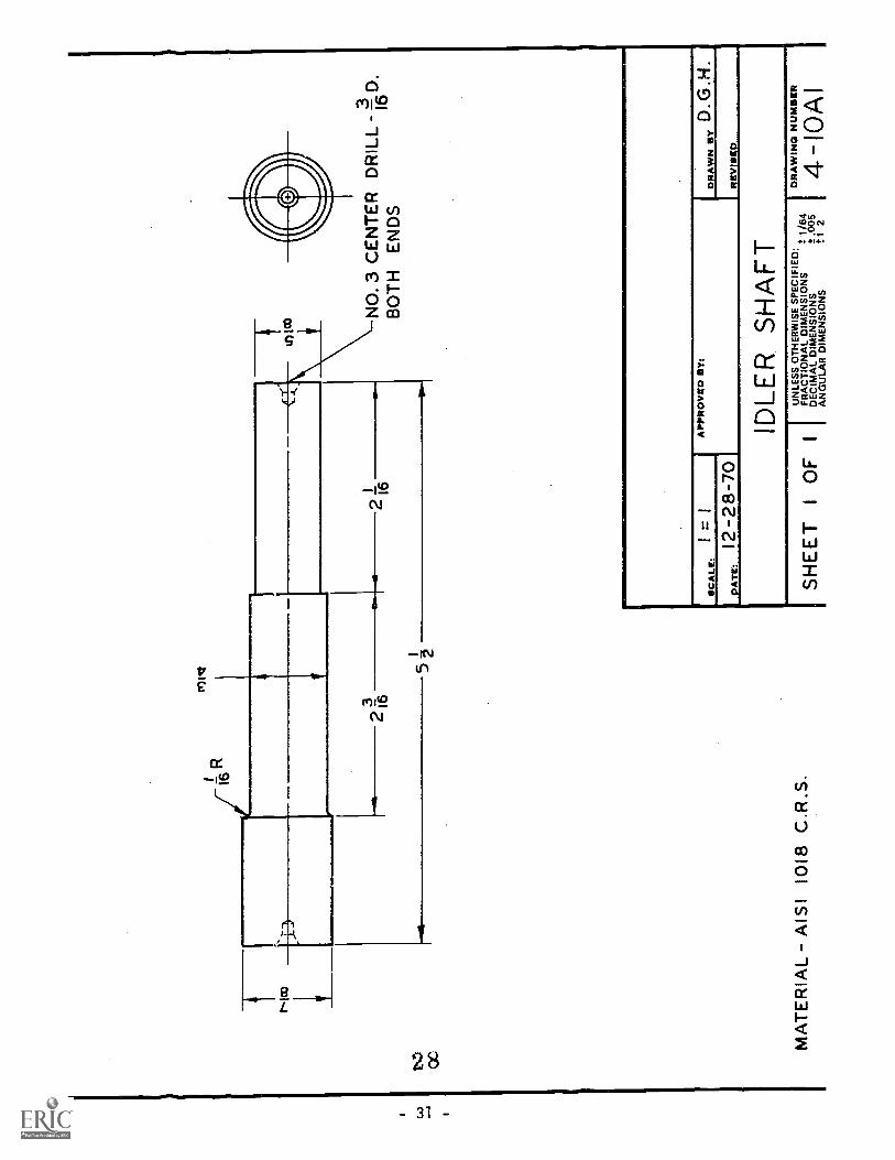
Job No. J-4-10-4
JOB SHEET
IDLER SHAFT
Drawing No. 4-10A1
EQUIPMENT: Lathe, power cutoff saw.
TOOLS: lathe dog 1/16" radius toolfile card 3" outside caliper6" steel rule 10" mill file#3 center drill left hand toolholder
SAFETY PRECAUTIONS:
right hand facing toolright hand turning toolJacobs drill chuck withMorse taper shank to fitlathe tailstock spindle
1. Observe all shop safety rules.2. Do not check 0.D. with calipers while the lathe is running.3. Check all dimensions carefully to limit material loss.4. Operate no equipment without authority to do so.
PROCEDURE:
1. Select 1" diameter C.R. steel, cut to 5-5/8" length on power cutoff saw.2. Mount work piece in 3 jaw universal chuck (refer to Operation Sheet
No. SL-1-25).3. Select proper spindle speed and feed (refer to Operation Sheet Nos.
SL-1-23 and SL-1-24).4. Face one end (refer to Operation Sheet Nos. SL-1-13, 17, and 26).5. Center drill (refer to Operation Sheet No. SL-1-1).6. Reverse work piece in chuck.7. Layout length as per print.8. Face to 5-1/2" length.9. Center drill.
10. Mount work piece between centers (refer to Operation Sheet Nos.SL-1-2 and SL-1-5).
11. Turn 7/8" diameter as close to lathe dog as possible (refer toOperation Sheet No. SL-1-4).
12. Reverse work piece between centers.. Turn 3/4" diameter 2-3/16" long (refer to Operation Sheet No. SL-1-6).
14. Form 1/16" radius between 7/8" diameter and 3/4" diameter.15. Turn 5/8" diameter 2-1/16" long.16. Break all sharp edges.17. Inspect as per print.
NOTE: Job No. 3-4-10-4 will be the material used for stud, Job No.J-5-10-5
- 29 -
27
M1V
2136
2 11
6N
O. 3
CE
NT
ER
DR
ILL
--3
D.
16B
OT
H E
ND
S
SC
ALE
:=
I
PA
M12
-28
-70
AP
PR
OV
RD
BY
:H
GD
DR
AW
. 51,
RIE
VIS
CP
IDLE
R S
HA
FT
SH
EE
T1
OF
1
4,,
I
UN
LES
S O
TH
ER
WIS
E S
PE
CIF
IED
:D
RA
WIN
G N
UM
BE
RF
RA
CT
ION
AL
DIM
EN
SIO
NS
- 1
i64
DE
CIM
AL
DIM
EN
SIO
NS
t .00
54-
I0A
lA
NG
ULA
R D
IME
NS
ION
St 1
2

Job No. J-5-10-5
EQUIPMENT: Lathe
rOOLS: lathe dogfile cardbench visecutting oil6" steel rulevise jaw caps
;AFETY PRECAUTIONS:
JOB SHEET
Drawing No. 5-10A1
STUD BOLT
micrometersmall "v" blocklathe collet set1/2"-13 N.C. dieand die stock
10" mill filesoft metal vise jawsleft hand toolholderstraight toolholderright hand facing toolright hand turning tool
1. Be careful not to run into lathe dog with turning tool.2. Observe all shop safety regulations.3. Check all dimensions carefully to limit material loss.4. Operate no equipment without authority to do so.
,ROCEDURE:
NOTE: Use Idler Shaft from Job No. J-4-10-4 as stock for this job.
1. Mount work piece between centers.2. Select proper spindle speed and feed.3. Turn 1/2" diameter to lathe dog (refer to Operation Sheet No. SL-3-8).
4. Reverse work piece and reposition lathe dog.
NOTE: Use soft metal strip to protect finished diameter from damage.
5. Finish turning 172" diameter.6. Mount work piece in collet (refer to Operation Sheet No. SL-1-16).7. Remove center by facing end and chamfer 1/32" x 450 as per print
(refer to Operation Sheet No. SL-1-17).8. Reverse work piece; face to length and chamfer 1/32" x 450 .
9. Grip work piece between vise jaw and "v" block, so that it projectsabout 2" above the vise jaws.
NOTE: Use soft metal jaws to protect work piece and "v" block.
10. Mount 1/2"-13-N-.C. die in die stock.
11. Chase 1 1/16" length of thread. Check thread with 1/2-13 N.C. nut.Use thread cutting oil (refer to Operation Sheet No. SL-3-7).
- 33-
'2 9

C.0
ri-I3
UN
C-
2AB
OT
H E
ND
S
5
2
NO
TE
: MA
KE
FR
OM
IDLE
R S
HA
FT
4-1
041
MA
TE
RIA
L -
NS
! -10
18 C
.R.S
.
x 45
° C
HA
MF
ER
32 BO
TH
EN
DS
SC
ALE
:I =
I
7
DA
TE
;12
-29-
70A
PP
RO
VE
D B
Y:
DR
AW
N B
YD
,G.H
RE
VIS
ED
ST
UD
BO
LT
IO
F I
UN
LES
S O
TH
ER
WIS
E S
PE
CIF
IED
:F
RA
CT
ION
AL
DIM
EN
SIO
NS
t 1 /6
4D
EC
IMA
L D
IME
NS
ION
St .
005
AN
GU
LAR
DIM
EN
SIO
NS
.4:1
2
DR
AW
ING
NU
MB
ER
5- 1
0AI
PR
EP
AR
ED
BY
TH
E D
EP
AR
TM
EN
T O
F V
OC
AT
ION
AL
ED
UC
AT
ION
-TH
E P
EN
NS
YLV
AN
IA S
TA
TE
UN
IVE
RS
ITY
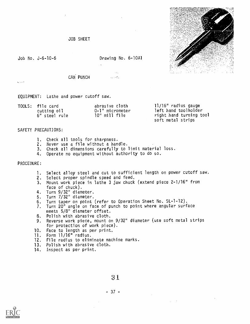
JOB SHEET
Job No. J-6-10-6 Drawing No. 6-10A1
CAN PUNCH
EQUIPMENT: Lathe and power cutoff saw.
TOOLS: file cardcutting oil6" steel rule
SAFETY PRECAUTIONS:
abrasive cloth0-1" micrometer10" mill file
-
11/16" radius aaugeleft hand toolholderright hand turning toolsoft metal strips
1. Check all tools for sharpness.2. Never use a file without a handle.3. Check all dimensions carefully to limit material loss.4. Operate no equipment without authority to do so.
PROCEDURE:
1. Select alloy steel and cut to sufficient length on power cutoff saw.2. Select proper spindle speed and feed.3. Mount work piece in lathe 3 jaw chuck (extend piece 2-1/16" from
face of chuck).4. Turn 9/32" diameter.5. Turn 7/32" diameter.6. Turn taper on point (refer to Operation Sheet No. SL-1-12).7. Turn 200 angle on face of punch to point where angular surface
meets 5/8" diameter offset.8. Polish with abrasive cloth.9. Reverse work piece, mount on 9/32" diameter (use soft metal strips
for protection of work piece).10. Face to length as per print.11. Form 11/16" radius.12. File radius to eliminate machine marks.13. Polish with abrasive cloth.14. Inspect as per print.
3 1
- 37 -

11.
SP
HE
RIC
AL
RA
D.
16
N.,
inR
Oiv
\i_00
01cv
Islc
r)
i 16
MA
TE
RIA
LA
IS1
4140
C.R
.S.
3
f
SC
ALE
:I
= I
DA
TE
: 12-
28-7
0
AP
PR
OV
ED
BY
:D
RA
WN
BY
D.G
.H.
RE
VIS
ED
CA
N P
UN
CH
SH
EE
TI
OF
I
UN
LES
S O
TH
ER
WIS
E S
PE
CIF
IEO
: ,,
FR
AC
TIO
NA
L O
IME
NS
ION
S=
1/6
4O
EC
IMA
L O
IME
NS
ION
S±
.005
AN
GU
LAR
OIM
EN
SIO
NS
± 1
2
DR
AW
ING
NU
MB
ER
6- 1
0A1
PR
EP
AR
ED
BY
TH
E D
EP
AR
TM
EN
T O
F V
OC
AT
ION
AL
ED
UC
AT
ION
TH
E P
EN
NS
YLV
AN
IA S
TA
TE
UN
IVE
RS
ITY

SC
RE
WD
WG
.NO
. 7-1
043
HA
ND
LED
WG
. NO
. 7-I
043
BA
SE
DW
G.N
O. 7
-10A
2
RO
DD
WG
. NO
. 7 -
I0A
3
11
SC
ALE
:
DA
TE
:8-
5-70
AP
PR
OV
ED
BY
:D
RA
WN
,D.G
.H.
RE
VIS
ED
DE
PT
H G
AG
E-A
SS
EM
BLY
SH
EE
T I
OF
3
PR
EP
AR
EO
BY
TH
E D
EP
AR
TM
EN
T O
F V
OC
AT
ION
AL
ED
UC
AT
ION
-TH
E P
EN
NS
YLV
AN
IA S
TA
TE
UN
IVE
RS
ITY
UN
LES
S O
TH
ER
WIS
E S
PE
CIF
IED
:F
RA
CT
ION
AL
DIM
EN
SIO
NS
. 1/6
4D
EC
IMA
L D
IME
NS
ION
S=
.005
AN
GU
LAR
DIM
EN
SIO
NS
t 1 2
DR
AW
ING
NU
MB
ER
7-1
OA
I

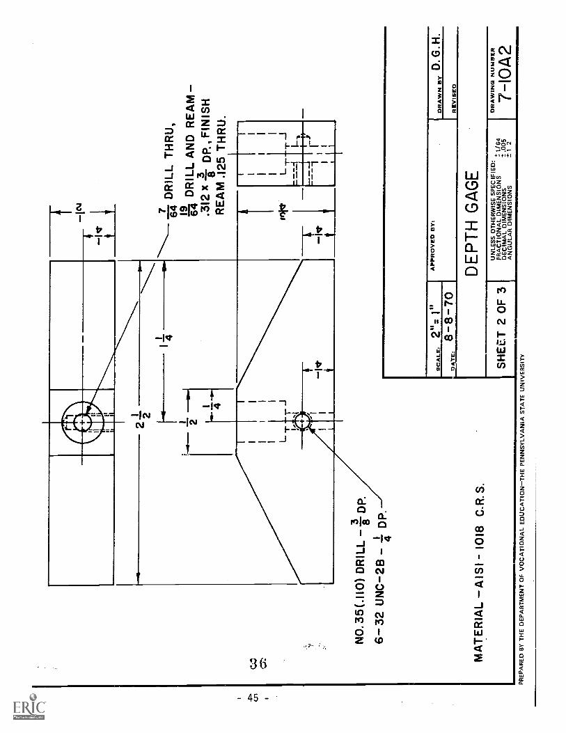
Job No. J-7-10-7
JOB SHEET
DEPTH GAUGE - BASE
Drawing No. 7-10A2
EQUIPMENT: Vertical milling machine, drill press, surface grinder and powercutoff saw.
TOOLS: scriberfile cardlayout dye7/64" drillprick punchcutting oilcenter punch
SAFETY PRECAUTIONS:
19/64" drillsurface gaugelayout hammer19/64" square bottom
drill#36 drill (.1065)
6-32 N.C. tap set10" mill fileT-handle tap wrench1/8" machine reamer5/16" machine reamercombination square set
1. Keep hands away from moving parts, cutters, tools and grindingwheels.
2. Clamp all work securely while machining.3. Check all dimensions carefully to limit material loss.4. Operate no equipment without authority to do so.
PROCEDURE:
1. Select material and cut to rough length on power cutoff saw2. Square off ends either by filing or milling (refer to Operation
Sheet Nos. SL-4-1, 2, 8, 9, 10, 11, and 12).3. Layout 1/2" wide dimension.4. Mount work piece in milling machine vise.5. Select proper speed and feed and mill to layout line (refer to
Operation Sheet No. SL-4-14).6. Layout angles.7. Remount work piece in milling machine vise.8. Use surface gauge to set layout lines parallel to machine table.9. Mill both angles to both layout lines.
10. Remove all burrs.11. Layout location of 5/16" reamed hole as per print.12. Layout location of 6-32 N.C. tapped hole as per print.13. Drill 7/64" hole through work piece using drill press.
- 43
3 t

) No. 3-7-10-7je 2
14. 19/64" counterbored hole.
NOTE: Use an adequate supply of cutting oil when drilling, reaming,
and tapping.
15. Ream 5/16" hole - 3/8" deep (refer to Operation Sheet No. SL-6-2).
16. Ream 7/64" hole with 1/8" machine reamer.
17. Drill #36 hole for 6-32 N.C. th-ead.
18. Tap 6-32 N.C.
19. Remove all burrs as per print.20. Mount work piece on surface grinder (refer to Operation Sheet Nos.
SL-7-1, 2, 3, 4, and 5).
21. Grind all flat surfaces.22. Remove all burrs left after surface grinding.
23. Inspect as per print.
3 5
- 44 -
----
7D
RIL
L T
HR
U,
64 19 pD
RIL
L A
ND
RE
AM
-.3
12 x
-38
- D
p'F
INIS
H'
RE
AM
.125
TH
RU
.
NO
.35(
.110
) D
RIL
L -
iD6-
32
UN
C-2
B -
--I
-D
P4
'
MA
TE
RIA
L -A
ISI -
101
8 C
.R.S
.
--
SC
ALE
:I"
AP
PR
OV
ED
BY
:D
RA
WN
BY
D. G
. H.
DA
TE
:8-
8-70
RE
VIS
ED
DE
PT
H G
AG
E
SH
EE
T 2
OF
3
PR
EP
AR
ED
BY
TH
E D
EP
AR
TM
EN
T O
F V
OC
AT
ION
AL
ED
UC
AT
ION
-TH
E P
EN
NS
YLV
AN
IA S
TA
TE
UN
IVE
RS
ITY
UN
LES
S O
TH
ER
WIS
E S
PE
CIF
IED
:F
RA
CT
ION
AL
DIM
EN
SIO
NS
± t/
64D
EC
IMA
L D
IME
NS
ION
S1.
005
AN
GU
LAR
DIM
EN
SIO
NS
-±1
2
DR
AW
ING
NU
MB
ER
7-10
A2

Job No. J-7-10-8
JOB SHEET
DEPTH GAUGE - HANDLE
EQUIPMENT: Lathe and power cutoff saw.
TOOLS: file cardlathe dogcutting oil7/64" drill3/16" drill6" steel rule
SAFETY PRECAUTIONS:
knurling tool#4 center drill0-1" micrometerlathe collet set10" mill file1/8" machine reamer
Drawing No. 7-10A3
left hand toolholderright hand facing toolJacobs drill chuck with
Morse taper to fitlathe tailstock spindle
right hand turning tool
1. Be careful not to run the tool into the lathe dog.
2. Observe all shop safety rules.3. Check all dimensions carefully to limit material loss.
4. Operate no equipment without authority to do so.
PROCEDURE:-
1. Select material and cut to rough length on power cutoff saw.2. Remove all burrs.3. Select proper spindle speed and feed.4. Mount work piece in collet, face and center drill first end.
5. Drill 3/16" hole (refer to Operation Sheet No. SL-1-18).6. Reverse work piece in collet, face to length and center drill.
7. Drill 7/64" hole.8. Ream hole (reduce speed 1/3 and use cutting oil - refer to Operation
Sheet No. SL-1-20).9. Mount work piece between centers with 1/8" hole in tailstock center,
3/16" hole in headstock center.10. Turn O.D. to13/32" diameter and length as specified.11. Knurl 13/32" diameter as per print (refer to Operation Sheet No.
SL-1-10).12. Turn 5/16" diameter as per print.13. Chamfer knurled end as per print.
14. Reverse piece between centers and protect knurled surface fromdamage with copper strip.
15. Machine diameter for press fit. Read print carefully. Note Tolerance!
16. Chamfer end as per print.:Remove all burrs.
18. Inspect as per print.0 070
- 47 -
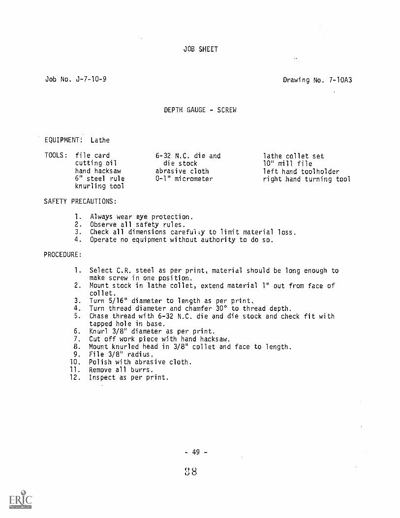
Job No. J-7-10-9
EQUIPMENT: Lathe
TOOLS: file cardcutting oilhand hacksaw6" steel ruleknurling tool
SAFETY PRECAUTIONS:
JOB SHEET
DEPTH GAUGE - SCREW
6-32 N.C. die anddie stock
abrasive cloth0-1" micrometer
Drawing No. 7-10A3
lathe collet set10" mill fileleft hand toolholderright hand turning tool
1. Always wear eye protection.2. Observe all safety rules.3. Check all dimensions carefully to limit material loss.4. Operate no equipment without authority to do so.
PROCEDURE:
1. Select C.R. steel as per print, material should be long enough tomake screw in one position.
2. Mount stock in lathe collet, extend material 1" out from face ofcollet.
3. Turn 5/16" diameter to length as per print.4. Turn thread diameter and chamfer 300 to thread depth.5. Chase thread with 6-32 N.C. die and die stock and check fit with
tapped hole in base.6. Knurl 3/8" diameter as per print.7. Cut off work piece with hand hacksaw.8. Mount knurled head in 3/8" collet and face to length.9. File 3/8" radius.
10. Polish with abrasive cloth.11. Remove all burrs.12. Inspect as per print.
- 49 -
88
JOB SHEET
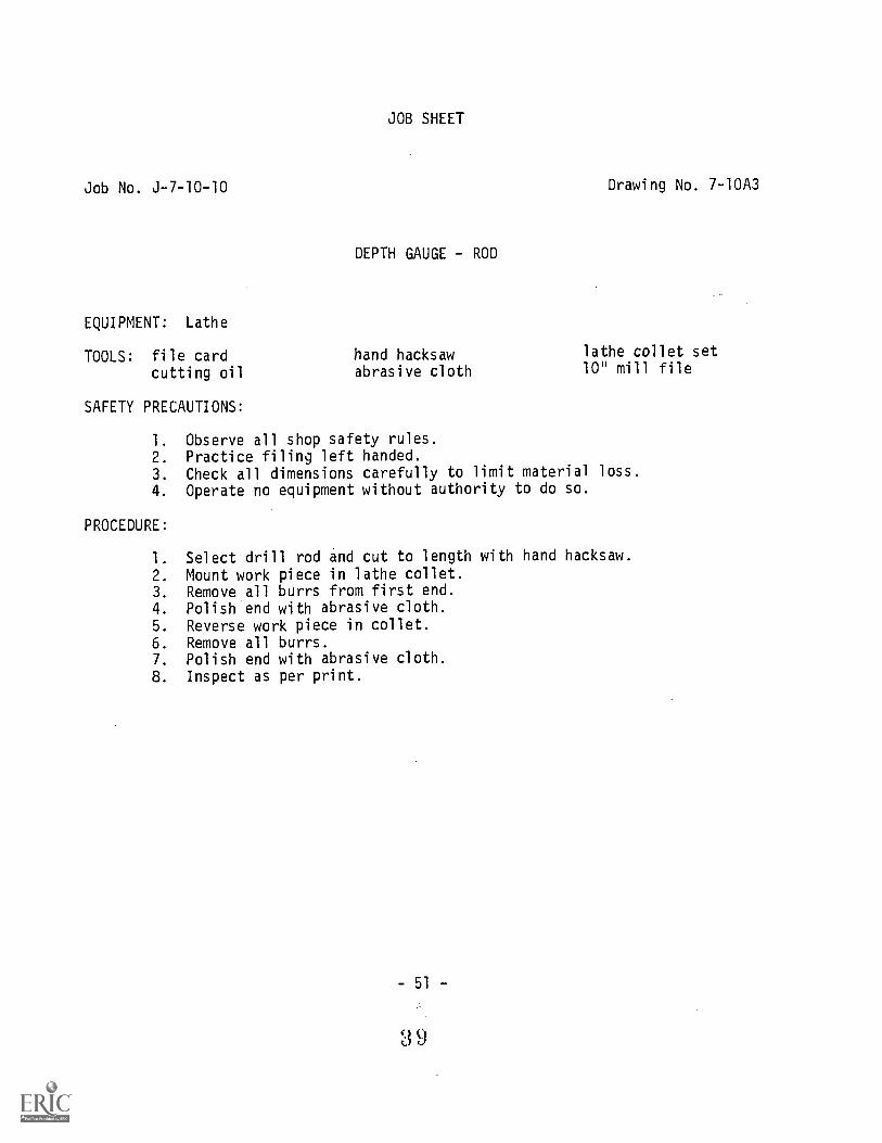
Job No. J-710-10 Drawing No. 7-10A3
DEPTH GAUGE - ROD
EQUIPMENT: Lathe
TOOLS: file cardcutting oil
SAFETY PRECAUTIONS:
hand hacksaw lathe collet set
abrasive cloth 10" mill file
1. Observe all shop safety rules.2. Practice filing left handed.3. Check all dimensions carefully to limit material loss.
4. Operate no equipment without authority to do so.
PROCEDURE:
1. Select drill rod and cut to length with hand hacksaw.
2. Mount work piece in lathe collet.3. Remove all burrs from first end.4. Polish end with abrasive cloth.5. Reverse work piece in collet.6. Remove all burrs.7. Polish end with abrasive cloth.8. Inspect as per print.
- 51 -
3 9

4 5°
CH
AM
FE
Rar
eM
ED
IUM
KN
UR
L3
R6
4'
ME
DIU
M K
NU
RL
030
CH
AM
FE
R T
OD
EP
TH
OF
TH
RE
AD
16
166-
32 U
NC
- 2A
SC
RE
W
SC
ALE
I"
MA
TE
RIA
L -H
AN
DLE
- A
ISI-
101
8 C
.R.S
.-S
CR
EW
- A
ISI -
1018
C.R
.S.
- R
OD
-DR
ILL
RO
D-A
ISI T
YP
E 0
2
x45
0 C
HF
R
2
HA
ND
LES
CA
LE 1
"-: I
13 16
5
RO
D
SC
ALE
In=
In
7 DR
ILL,
64 1 8R
EA
M
1
SC
ALE
:
DA
TE
:
AS
SH
OW
N
18-
10-7
0A
PP
RO
VE
D B
Y:
ED
RA
WN
BY
RE
VIS
ED
DE
PT
H G
AG
E -
DE
TA
ILS
SH
EE
T 3
OF
3U
NLE
SS
OT
HE
RW
ISE
SP
EC
IFIE
D:
FR
AC
TIO
NA
L D
IME
NS
ION
S1/
64D
EC
IMA
L D
IME
NS
ION
S±
.005
AN
GU
LAR
DIM
EN
SIO
NS
t 12
DR
AW
ING
NU
MB
ER
7-10
A3
PR
EP
AR
ED
WY
TH
E D
EP
AR
TM
EN
T O
F V
OC
AT
ION
AL
ED
UC
AT
ION
-TH
E P
EN
NS
YLV
AN
IA S
TA
TE
UN
IVE
RS
ITY

tf:a
.
1111
1110
1111
SC
RE
WD
WG
. NO
. 8-I
0A4
CA
PD
WG
. NO
. 8-I
0A5
./\-
-BO
DY
HA
ND
LED
WG
. NO
. 8-I
0A5
DW
GS
. NO
.8-1
0A2
& N
O. 8
-I0A
3
AP
PR
OV
ED
BY
:S
CA
LE:
mum
8-3-
70D
RA
WN
BY
D.G
.H.
RE
VIS
ED
C-C
LAM
P -
AS
SE
MB
LY
SH
EE
T I
OF
5U
NLE
SS
OT
HE
RW
ISE
SP
EC
IFIE
D: *
FR
AC
TIO
NA
L D
IME
NS
ION
S11
64D
EC
IMA
L D
IME
NS
ION
S4
.005
AN
GU
LAR
DIM
EN
SIO
NS
± 1
2
DR
AW
IND
NU
MB
ER
8-10
AI
PR
EP
AR
EO
BY
TH
E D
EP
AR
TM
EN
T O
F V
OC
AT
ION
AL
ED
UC
AT
ION
-TH
E P
EN
NS
YLV
AN
IA S
TA
TE
UN
IVE
RS
ITY

Job No. J-8-10-11
JOB SHEET
C-CLAMP - BODY
Drawing Nos. 8-10A2and 8-10A3
EQUIPMENT: Power cutoff saw, drill press, and vertical milling machine.
TOOLS: scriberfile card1/2" drilllayout dyeprick punch3" dividers3/16" drill
SAFETY PRECAUTIONS:
5/16" drillcenter punchlayout hammerhand hacksaw6" steel rulecenter finderabrasive cloth
#3 center drillcombination square10" mill file3/8" - N.C. tap setadjustable tap wrench10" flat filecutting oil
1. Always clamp job securely in vise before drilling.2. Do not wear loose clothing near revolving spindles, drills, or
gears.3. Check all dimensions carefully to limit material loss.4. Operate no equipment without authority to do so.
PROCEDURE:
1. Select C.R. steel and cut to rough length on power cutoff saw.2. Mount work piece on milling machine.3. Machine ends square and to length as per print.4. Layout finish lines on clamp body as per print 8-10A2.5. Layout, prick punch, and center punch for 1/2" holes to produce
1/4" radii on inside section of clamp body as per print 8-10A3.6. Layout, prick punch, and center punch for a series of 3/16" holes
to facilitate removal, by hand hacksaw, of excess stock on insidesection of clamp body as per print 8-10A3.
7. Drill holes as per print using drill press.8. Transfer work piece to bench vise and use hand hacksaw to remove
excess stock.9. File inside section to layout lines.
10. Saw corner of jaw according to print using hand hacksaw.11. File outline of jaw body to layout lines paying particular attention
to the angle on the jaw and the 1/4" radii on the outside corners ofthe jaw body.
57 -
4 9
Job No. J-8-10-11Page 2
12. Layout, prick punch, and center punch location for tapped hole.13. Position in drill press vise and locate center of hole with
center finder.14. Center drill to mark starting location for threaded hole.15. Drill 5/16" hole.16. Tap hole using center point in drill chuck to ensure proper
alignment of tap.17. Remove all burrs.18. Draw file all over.19. Polish with abrasive cloth.20. Inspect as per print.
- 58

A-1
6 U
NC
- 28
a
CJ
5 a
=
3I 2
21 4
5 16
NO
TE
S:
I. S
EE
DW
G. N
O. 8
-I04
3 F
OR
LA
YO
UT
OF
INS
IDE
OP
EN
ING
.2.
BR
EA
K A
LL S
HA
RP
ED
GE
S.
MA
TE
RIA
L -
AIS
I -10
18 C
.R.S
.
I"
I"
SC
ALE
.2
DA
TE
:7-
10-7
0A
PP
RO
VE
D B
Y:
DR
AW
N B
YD
.G.H
.R
EV
ISE
D
C-C
LAM
P-
BO
DY
SH
EE
T 2
OF
5U
NLE
SS
OT
HE
RW
ISE
SP
EC
IFIE
D:
FR
AC
TIO
NA
L D
IME
NS
ION
S1/
64D
EC
IMA
L D
IME
NS
ION
S.0
05A
NG
ULA
R D
IME
NS
ION
S".
1" 1
2
DR
AW
ING
NU
MB
ER
8-10
A2
PR
EP
AR
ED
BY
TH
E D
EP
AR
TM
EN
T O
F V
OC
AT
ION
AL
ED
UC
AT
ION
-TH
E P
EN
NS
YLV
AN
IA S
TA
TE
UN
IVE
RS
ITY

tiab, Cii
==
==
==
t-10
.1
3 -1 6
DIA
.- 1
3 H
OLE
S
uij-T
YP
.I 7
1-2- D
IA*-
2 H
OLE
S
SC
ALE
:
DA
TE
:8
-3-7
0A
PP
RO
VE
D B
Y:
DR
AW
N B
YD
.G. H
.
RE
VIS
ED
C-C
LAM
P-
BO
DY
I_A
YO
UT
SH
EE
T 3
OF
5-1
1,U
NLE
SS
OT
HE
RW
ISE
SP
EC
IF I
ED
:F
RA
CT
ION
AL
DIM
EN
SIO
NS
1114
DE
CIM
AL
DIM
EN
SIO
NS
AN
GU
LAR
DIM
EN
SIO
NS
2
PR
EP
AR
ED
BY
TH
E D
EP
AR
TM
EN
T O
F V
OC
AT
ION
AL
ED
UC
AT
ION
-TH
E P
EN
NS
YLV
AN
IA S
TA
TE
UN
IVE
RS
ITY
DR
AW
ING
NU
MB
ER
8-I0
A3

Job No. J-8-10-12
JOB SHEET
C-CLAMP - SCREW
EQUIPMENT: Lathe, drill press, and power cutoff saw.
TOOLS: scriberfile cardcutting oilcenter gaugescrew-pitch gauge6" steel ruleabrasive clothlayout dye
SAFETY PRECAUTIONS:
#1 center drill0-1" micrometer#13 drill (.185)600 threading tool10" mill filelathe collet setlayout hammerprick punch
Drawing No. 8-10A4
straight toolholderright hand facing toolJacobs drill chuck withMorse taper to fitlathe tailstock spindle
right hand turning toolcenter punch
1. Loose clothing apparel is dangerous around moving machinery.2. Observe all shop safety rules.3. Check all dimensions carefully to limit material loss.4. Operate no equipment without authority to do so.
PROCEDURE:
1. Select round C.R. steel.2. Cut stock to rough length on power cutoff saw.3. Mount stock in lathe collet and face both ends, finish to length as
per print.4. Center drill one end.5. Turn 3/8" diameter as per print.6. Set up lathe for threading (refer to Operation Sheet No. SL-1-11).7. Chase 3/8" - 16 N.C. threads as per print.8. Check thread fit with tapped hole in clamp body.9. Turn 1/4" diameter and chamfer 300 to thread depth.
10. Reverse work piece in collet.11. File rounded face on large diameter.12. Layout and drill #13 hole.13. Remove all burrs.14. Polish rounded end and large diameter with abrasive cloth.15. Inspect as per print.
- 63 -
4 6

NO
.13
(.18
5) D
RIL
L
0
30 C
HA
MF
ER
TO
DE
PT
H O
F T
HR
EA
D
16
MA
TE
RIA
L -
AI S
I -10
18 C
.R. S
.
NO
.2 C
EN
TE
R D
RIL
L -
ril D
IA.
IS
CA
LE:
7-
70A
PP
RO
VE
D B
Y:
DR
AW
N B
YD
.G.H
.
RE
VIS
ED
CC
LAM
P-S
CR
EW
SH
EE
T 4
OF
5U
NLE
SS
OT
HE
RW
ISE
SP
EC
IFIE
D:
FR
AC
TIO
NA
L D
IME
NS
ION
S±
1 /6
4D
EC
IMA
L D
IME
NS
ION
S±
.005
AN
GU
LAR
DIM
EN
SIO
NS
12
DR
AW
ING
NU
MB
ER
8-10
A4
PR
EP
AR
ED
BY
TH
E D
EP
AR
TM
EN
T O
F V
OC
AT
ION
AL
ED
UC
AT
ION
-TH
EP
EN
NS
YLV
AN
IA S
TA
TE
UN
IVE
RS
ITY

Job No. J-8-10-13
EQUIPMENT: Lathe
TOOLS: file card1/4" drillcutting oil6" steel ruleparting bladeand holder
SAFETY PRECAUTIONS:
JOB SHEET
C-CLAMP - SCREW CAP
abrasive cloth#4 center drill3/8" counterborelathe collet set10" mill filestraight toolholder
Drawing No. 8-10A5
right hand facing toolleft hand toolholderJacobs drill chuck with
Morse taper to fitlathe tailstock spindle
right hand turning tool
1. Remove cutting tools from lathe toolholders before performingother operations.
2. Check all dimensions carefully to limit material loss.3. Operate no equipment without authority to do so.
PROCEDURE:
1. Select round C.R. steel.2. Mount in collet and face one end.3. Center drill end.4. Drill 1/4" hole about 1/2" deep.5. Counterbore 5/16" diameter.6. Set compound at 34° with center line so that small end of taper is
at headstock end of lathe.7. Turn angle as per print.8. Remove all burrs.9. Polish with abrasive cloth.
10. Part off to length (refer to Operation Sheet No. SL-1-22).11. Remove burrs caused by parting.12. Inspect as per print.
- 67 -
4 8

JOB SHEET
Job No. J-8-10-14 Drawing No. 8-10A5
C-CLAMP - HANDLE
EQUIPMENT: Lathe
TOOLS: file cardcutting oilhand hacksaw
SAFETY PRECAUTIONS:
6" steel rule lathe collet setabrasive cloth 10" mill file
1. Never use a file without a handle.2. Check all dimensions carefully to limit material loss.3. Operate no equipment without authority to do so.
PROCEDURE:
1. Select round C.R. steel as per print.2. Cut to length using hand hacksaw.3. Mount work piece in lathe collet and form radii on ends using file.4. Polish with abrasive cloth.5. Inspect as per print.

CR
C.."
'.
CA
P
iD
RIL
L
MA
TE
RIA
L -
A IS
1- 1
018
C.R
.S.
2i 4
HA
ND
LE
SC
ALE
:..
I'P
TE
;7-
11-7
0A
PP
RO
VE
D B
Y:
DR
AW
N B
YD
. G.H
.
RE
VIS
ED
C-C
LAM
P-
DE
TA
ILS
SH
EE
T 5
OF
5U
NLE
SS
OT
HE
RW
ISE
SP
EC
IFIE
D:
FR
AC
TIO
NA
L D
IME
NS
ION
S=
1/6
4D
EC
IMA
L D
IME
NS
ION
S=
.005
AN
GU
LAR
DIM
EN
SIO
NS
t. 1
2
DR
AW
ING
NU
MB
ER
8-I0
A5
PR
EP
AR
ED
BY
TH
E D
EP
AR
TM
EN
T O
F V
OC
AT
ION
AL
ED
UC
AT
ION
-TH
E P
EN
NS
YLV
AN
IA S
TA
TE
UN
IVE
RS
ITY
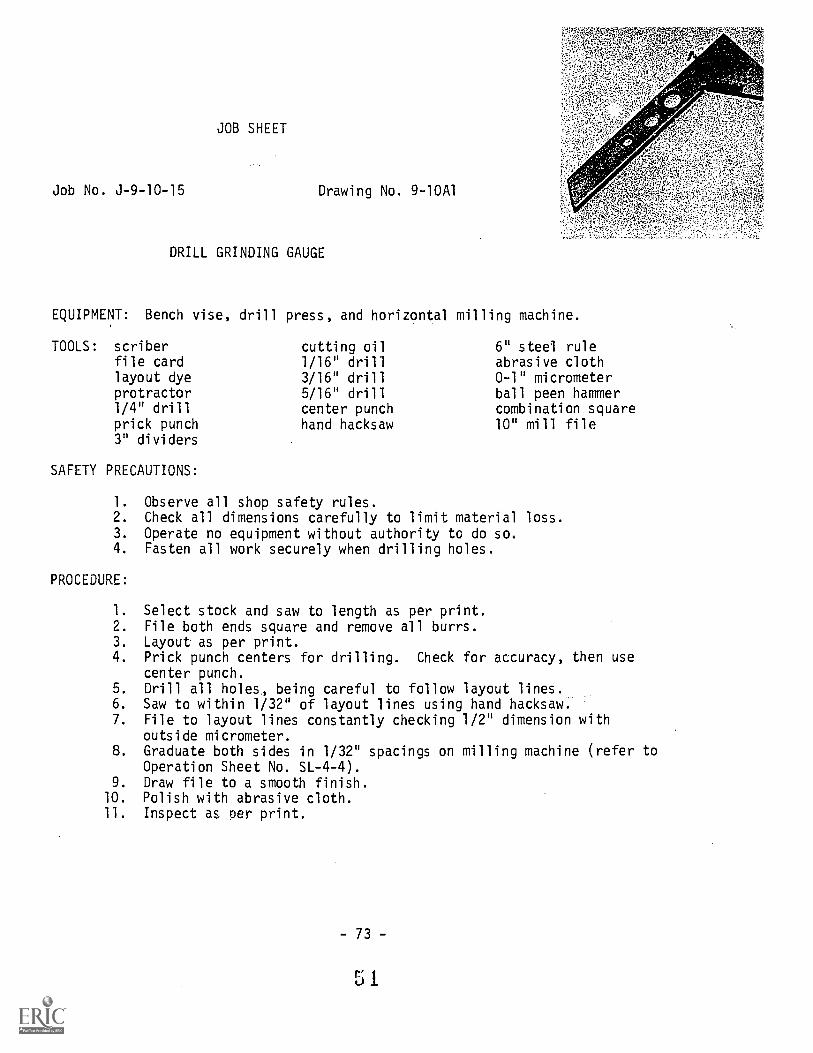
JOB SHEET
Job No. J-9-10-15 Drawing No. 9-10A1
DRILL GRINDING GAUGE
EQUIPMENT: Bench vise, drill press, and horizontal milling machine.
TOOLS: scriberfile cardlayout dyeprotractor1/4" drillprick punch3" dividers
SAFETY PRECAUTIONS:
cutting oil1/16" drill3/16" drill5/16" drillcenter punchhand hacksaw
6" steel ruleabrasive cloth0-1" micrometerball peen hammercombination square10" mill file
1. Observe all shop safety rules.2. Check all dimensions carefully to limit material loss.3. Operate no equipment without authority to do so.4. Fasten all work securely when drilling holes.
PROCEDURE:
1. Select stock and saw to length as per print.2. File both ends square and remove all burrs.3. Layout as per print.4. Prick punch centers for drilling. Check for accuracy, then use
center punch.5. Drill all holes, being careful to follow layout lines.6. Saw to within 1/32" of layout lines using hand hacksaw.7. File to layout lines constantly checking 1/2" dimension with
outside micrometer.8. Graduate both sides in 1/32" spacings on milling machine (refer to
Operation Sheet No. SL-4-4).9. Draw file to a smooth finish.
10. Polish with abrasive cloth.11. Inspect as per print.
73 -

32 G
RA
DU
AT
ION
SP
ER
INC
H,
BO
TH
SID
ES
3 -6D
RIL
L
DR
ILL
4
MA
TE
RIA
L- A
ISI
1018
C.R
.S.
SC
ALE
:I
=I
AP
PR
OV
ED
BY
:D
RA
WN
BY
D.G
.H.
DA
TE
:1
2-2
9-70
RE
VIS
ED
DR
ILL
GR
IND
ING
GA
GE
SH
EE
TI
OF
I
PR
EP
AR
ED
BY
TH
E D
EP
AR
TM
EN
T O
F V
OC
AT
ION
AL
ED
UC
AT
ION
TH
E P
EN
NS
YLV
AN
IA S
TA
TE
UN
IVE
RS
ITY
UN
LES
S O
TH
ER
WIS
E S
PE
CIF
IED
:F
RA
CT
tON
AL
DIM
EN
SIO
NS
; 1/6
4D
EC
IMA
L E
ME
NS
ION
SZ
.005
AN
GU
LAR
DIM
U4S
ION
St 1
2Ic
.tr.a
rze,
er
DR
AW
ING
NU
MB
ER
9- 1
0AI

LOO
SE
JA
WD
WG
. NO
.10-
10A
3
AD
JUS
TIN
G S
CR
EW
DW
G. N
O. I
0-10
A4
co:.
RO
UN
D H
EA
D S
CR
EW
8-32
,4-
LG.
ST
RA
IGH
T C
LIP
DW
G. N
O. I
0-10
A4
=.2
474
yTH
RE
AD
ED
JA
WD
WG
. NO
. 10-
10A
2
CLA
MP
ING
SC
RE
WD
WG
. I0-
10A
4
SC
ALE
-
DA
TE
:
AP
PR
OV
ED
BY
:D
. G. H
.D
RA
WN
SY
9 - 2
6-76
1I
RE
VIS
ED
PA
RA
LLE
L C
LAM
P- A
SS
EM
BLY
SH
EE
T 1
OF
4U
NLE
SS
OT
HE
RW
ISE
SP
EC
IFIE
D:
FR
AC
TIO
NA
L D
IME
NS
ION
S±
1164
DE
CIM
AL
DIM
EN
SIO
NS
± .0
05A
NG
ULA
R D
IME
NS
ION
S±
-1 2
DR
AW
ING
NU
MB
ER
10-1
0A I
PR
EP
AR
ED
BY
TH
E D
EP
AR
TM
EN
T O
F V
OC
AT
ION
AL
ED
UC
AT
ION
-TH
E P
EN
NS
YLV
AN
IA S
TA
TE
UN
IVE
RS
ITY

JOB SHEET
Job No. J-10-10-16 Drawing No. 10-10A2
PARALLEL CLAMP - THREADED JAW
EQUIPMENT: Power cutoff saw, horizontal milling machine, drill press and heattreating furnace.
TOOLS: tongsscriberfile cardlayout dyeprick punchcutting oil3" dividers
SAFETY PRECAUTIONS:
center punchhand hacksaw6" steel rulelayout hammerabrasive clothasbestos gloves
"I" drill (.272)combination square10" mill fileadjustable tap wrench5/16"-24 N.F. tap setcase hardening compound
1. Never leave a machine unattended while it is in operation.2. Always report all accidents.3. Check all dimensions carefully to limit material loss.4. Operate no equipment without authority to do so.
PROCEDURE:
1. Select material and cut to rough length on power cutoff saw.2. Mount work piece on milling machine.3. Square both ends and finish to required length.4. Layout and mill angle.5. Layout jaw for tapped holes.6. Drill jaw for tapping, two holes required.7. Tap two holes.8. File radius at end of angle.9. File radius at square end of jaw.
10. Draw file all over.11. Polish with abrasive cloth.12. Case harden.13. Repolish with abrasive cloth.14. Inspect as per print.
- 79 -
54

C.;
IR
MA
TE
RIA
L -
AIS
I 101
8 C
.R.S
.H
EA
T T
RE
AT
ME
NT
- C
AS
E H
AR
DE
N
(.27
2) D
RIL
L,5 rg
-2 4
UN
F -
2B
,2
HO
LES
SC
ALE
:II
AP
PR
OV
ED
BY
:D
RA
WN
BY
D. G
. H.
DA
TE
:9
-19-
70R
EV
ISE
D
PA
RA
LLE
L C
LAM
P-T
HR
EA
DE
D J
AW
SH
EE
T 2
0F 4
UN
LES
S O
TH
ER
WIS
E S
PE
CIF
IED
:F
RA
CT
ION
AL
DIM
EN
SIO
NS
t 1 /6
4D
EC
IMA
L D
IME
NS
ION
S.0
05A
NG
ULA
R D
IME
NS
ION
St 1
2
DR
AW
ING
NU
MB
ER
10-1
042
PR
EP
AR
ED
BY
TH
E D
EP
AR
TM
EN
T O
F V
OC
AT
ION
AL
ED
UC
AT
ION
-TH
E P
EN
NS
YLV
AN
IA S
TA
TE
UN
IVE
RS
ITY

Job No. J-10-10-17
JOB SHEET
PARALLEL CLAMP - LOOSE JAW
Drawing No. 10-10A3
EQUIPMENT: Power cutoff saw, milling machine, drill press, and heat treatingfurnace.
TOOLS: tongsscriberfile cardlayout dyecutting oilprick punch3" dividers
SAFETY PRECAUTIONS:
21/64" drillcenter punchlayout hammerabrasive clothasbestos gloves"I" drill (.272)case hardening compound
#28 drill (.1405)8-32 N.F. tap set7/16" counterborecombination square10" mill fileT-handle tap wrench
1. Secure work by clamp or vise. Never hold with hands.2. Never attempt measurements while machine is in motion.3. Check all dimensions carefully tn limit material loss.4. Operate no equipment withoji, authority to do so.
PROCEDURE:
1. Select material and cut tu rough lJngth on power cutoff saw.2. Mount work piece on milling machine.3. Square both ends and finish to required length.4. Layout and machine angie as per print.5. Layout holes as per print,6. Drill 21/64" hole and counterbore as per print.7. Drill and tap 8-32 N.F. hole for clip.8. Drill blind hole on opposite side from counterbore as per print.9. File radius at end of angle.
10. File radius at square end of jaw.11. Draw file all over.12. Polish with abrasive cloth.13. Case harden.14. Repolish with abrasive cloth.15. Inspect as per print.
- 83 -
0.c

DR
ILL,
647
IC
'BO
RE
--g
X -
- D
Ri
8
1N
O. 2
9 (.
136)
DR
ILL,
-i D
P,
8-32
UN
C-2
8
5
I
-6
MA
TE
RIA
L -
A IS
I10
18 C
.R.S
.H
EA
T T
RE
AT
ME
NT
- C
AS
E H
AR
DE
N
4
5 16
II
111.
=11
1111
1=11
.
I (.2
72)
DR
ILL,
5 rd-
DE
EP
Iit
=III
SC
ALE
:
DA
TE
:9
-19-
70
AP
PR
OV
ED
BY
:D
RA
WN
By
D. G
.1-
RE
VIS
ED
PA
RA
LLE
L C
LAM
P- L
OO
SE
JA
W
SH
EE
T3
OF
4U
NLE
SS
OT
HE
RW
ISE
SP
EC
IHE
D:
FR
AC
TIO
NA
L D
IME
NS
ION
SD
EC
IMA
L D
IME
NS
ION
SA
NG
ULA
R D
IME
NS
ION
S
-"t 1
/64
± .0
05±
1 2
PR
EP
AR
ED
BY
TH
E D
EP
AR
TM
EN
T O
F V
OC
AT
ION
AL
ED
UC
AT
ION
-TH
E P
EN
NS
YLV
AN
IA S
TA
TE
UN
IVE
RS
ITY
DR
AW
ING
NU
MB
ER
I 0-1
0A3

Job No. J-10-10-18
EQUIPMENT: Drill press
TOOLS: scriberfile cardlayout dye3" dividersprick punch
SAFETY PRECAUTIONS:
JOB SHEET
PARALLEL CLAMP - STRAIGHT CLIP
11/64" drill
center punch6" steel rulehand hacksawlayout hammer
Drawing No. 10-10A4
abrasive cloth6" mill filecombination square6" round file
1. Never attempt to clean a taper hole in a spindle while it isrevolving.
2. Always remove the chuck key after fastening a drill in a chuck.3. Check all dimensions carefully to limit material loss.4. Operate no equipment without authorization.
PROCEDURE:
1. Select correct gauge of sheet steel and cut to length using handhacksaw.
2. Layout according to print.3. Drill 11/64" hole.4. Cut to layout lines.5. File radii as required.6. Remove all burrs.7. Polish with abrasive cloth.8. Inspect as per print.
- 87 -
58

Job No. J-10-10-19
JOB SHEET
PARALLEL CLAMP - ADJUSTING'SCREW
EQUIPMENT: Lathe and power cutoff saw
TOOLS: file cardlathe dogcenter gaugecutting oilscrew-pitch gauge6" steel ruleknurlinc; tool
SAFETY PRECAUTIONS:
#3 center drill0-1" micrometerlathe collet set10" mill file1/16" necking tool600 threading toolstraight toolholder
Drawing No. 10-10A4
left hand toolholderright hand facing toolright hand turning toolJacobs drill chuck withMorse taper to fitlathe tailstock spindle
1. Never attempt to clean metal particles from knurl while rolls arein motion.
2. Always stop the lathe before making any adjustment.3. Check all dimensions carefully to limit material loss.4. Operate no equipment without authorization to do so.
PROCEDURE:
1. Select material and cut to rough length on power cutoff saw.2. Mount work piece in lathe collet or chuck.3. Face one end and center drill.4. Face opposite end and center drill allowing sufficient additional
material to permit removal of center holes when machining operationsbetween centers are completed.
5. Mount work piece between centers.6. Turn 1/2" diameter as close to lathe dog as possible.7. Knurl diameter allowing for removal of center when finishing screw.8. Reverse work piece between centers (protect knurl with soft metal).9. Turn thread diameter allowing additional length for center
removal when finishing screw.10. Turn 7/16" diameter and neck 1/16" groove to 21/64" diameter (refer
to Operation Sheet No. SL-1-8).11. Chase threads and fit to threaded jaw.12. Mount work piece in collet, face off both centers and finish to
length.13 Turn off 1/16" wide band of knurling to 7/16" diameter at each end
of knurled head as per print.14. File radius on each end.15. Remove all sharp edges.16. Inspect as per print.
- 89 -
5 9
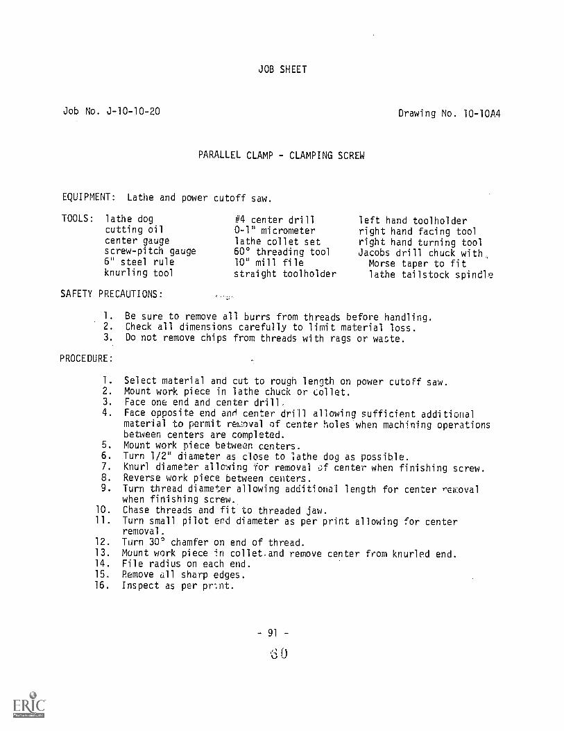
Job No. J-10-10-20
JOB SHEET
PARALLEL CLAMP - CLAMPING SCREW
EQUIPMENT: Lathe and power cutoff saw.
TOOLS: lathe dogcutting oilcenter gaugescrew-pitch gauge6" steel ruleknurling tool
SAFETY PRECAUTIONS:
#4 center drill0-1" micrometerlathe collet set600 threading tool10" mill filestraight toolholder
Drawing No. 10-10A4
left hand toolholderright hand facing toolright hand turning toolJacobs drill chuck with,Morse taper to fitlathe tailstock spindle
1. Be sure to remove all burrs from threads before handling.2. Check all dimensions carefully to limit material loss.3. Do not remove chips from threads with rags or waste.
PROCEDURE:
1. Select material and cut to rough length on power cutoff saw.2. Mount work piece in lathe chuck or collet.3. Face one end and center drilL4. Face opposite end anri center drill allowing sAifficient additional
material to permit reffloval of center holes when machining operationsbetween centers are completed.
5. Mount work piece between centers.6. Turn 1/2" diameter as close to lathe dog as possible.7. Knurl diameter allowing for removal center when finishing screw.8. Reverse work piece between centers.9. Turn thread diameter allowing additional length for center rewoval
when finishing screw..10. Chase threads and fit to threaded jaw.11. Turn small pilot erd diameter as per print allowing for center
removal.12. Turn 300 chamfer on end of thread.13. Mount work piece in collet.and remove center from knurled end.14. File radius on each end.15. Remove all sharp edges.16. Inspect as per prnt.
- 91 -
0

co"1
5 r-6D
IA ti
CU
T- M
ED
. KN
UR
L
3I 83-
12 324
I 2
AD
JUS
TIN
G S
CR
EW
ST
RA
IGH
T C
LIP
MA
TE
RIA
L A
ISI
1018
C.R
.S.
524
UN
F -
2A
16
ME
D. K
NU
RL
1 16-4
116
.6"
I
gii:4
:7::1
3;.ll
ll II
II 32 -.41
1
22L 32 8
CLA
MP
ING
SC
RE
W
3R
111
SC
ALE
:
DA
TE
.9-
19-7
0A
PP
RO
VE
D B
Y:
DR
AW
N B
YD
.G.H
.R
EV
ISE
D
PA
RA
LLE
L C
LAM
P-D
ET
AIL
S
SH
EE
T4
OF
4U
NLE
SS
OT
HE
RW
ISE
SP
EC
IFIE
D:
FR
AC
TIO
NA
L D
IME
NS
ION
SD
EC
IMA
L D
IME
NS
ION
SA
NG
ULA
R D
IME
NS
ION
S
t 1/6
4t .
005
+.1
2
PR
EP
AR
ED
BY
TH
E D
EP
AR
TM
EN
T O
F V
OC
AT
ION
AL
ED
UC
AT
ION
-TH
EP
EN
NS
YLV
AN
IA S
TA
TE
UN
IVE
RS
ITY
DR
AW
ING
NU
MB
ER
I0-1
0A4

WR
EN
CH
HA
ND
LE2
RE
QU
IRE
DD
WG
. NO
. 11-
104
2
TH
UM
B S
CR
EW
2 R
EQ
UIR
ED
DW
G. N
O.1
1-10
42
SC
ALE
:
DA
TE
:8-
14-7
0A
PP
RO
VE
D B
Y:
DR
AW
N B
YD
. G. H
.
RE
VIS
ED
TA
P W
RE
NC
H- A
SS
EM
BLY
SH
EE
T 1
OF
2U
NLE
SS
OT
HE
RW
ISE
SP
EC
IFIE
D:
± 1
/64
FR
AC
TIO
NA
L D
IME
NS
IDN
SD
EC
IMA
L D
IME
NS
ION
S±
.005
AN
GU
LAR
DIM
EN
SIO
NS
*1 2
DR
AW
ING
NU
MB
ER
II-10
A I
PR
EP
AR
ED
BY
TH
E D
EP
AR
TM
EN
T O
F V
OC
AT
ION
AL
ED
UC
AT
ION
-TH
E P
EN
NS
YLV
AN
IA S
TA
TE
UN
IVE
RS
ITY

JOB SHEET
Job No. J-11-10-21 Drawing No. 11-10A2
TAP WRENCH - HANDLES
EQUIPMENT: Power cutoff saw, drill press, bench vise, lathe, and heat treatingfurnace.
TOOLS: tongsscriberfile card1/4" drilllayout dyecutting oilprick punchcenter punch6" steel ruleknurling tool
SAFETY PRECAUTIONS:
abrasive clothsoft vise jawsasbestos gloves#3 center drill#7 drill (.201)outside caliperslathe collet set10" mill file3/16" radius gaugeadjustable tap wrench
straight toolholder1/4"-20 N.C. tap set6" square needle file6" combination squareleft hand toolholderright hand facing toolright hand turning toolJacobs drill chuck withMorse taper to fitlathe tailstock spindle
1. Observe all shop safety regulations.2. Check all dimensions carefully to limit material loss.3. Operate no equipment without authority to do so.
PROCEDURE:
1. Select and cut 2 pieces of square C.R. steel on power cutoff saw,allowing 1/4" additional material at one end for center drilling.
NOTE: The same procedure is to be followed for both handles.
2. Mount work piece in 4 jaw chuck.3. Face and center drill. Do not exceed 1/4" depth.4. Support work piece with dead center.5. Turn 3/8" diameter.6. Knurl to specified length allowing for removal of center hole.7. Repeat steps 2 through 6 for second handle.8. Mount in collet and remove center hole. (Both handles)9. Form radius on handle end as per print. (Both handles)
10. Reverse work piece in collet and face to length.
NOTE: Work pieces should be set up and drilled together to insurealignment of holes. See assembly drawing.
- 97 -
6 3

Job No. J-11-10-21Page 2
11. Layout for tapped holes, clearance holes, and 900 notch.12. Drill #7 holes to be tapped.13. Drill clearance holes.14. Tap 1/41t-20 N.C. hole in each work piece.15. File 90° notch in each work piece to form a"square when matched
together.16. Break all sharp corners.17. Polish with abrasive cloth.18. Case harden.19. Repolish with abrasive cloth.20. Inspect as per print.
- 98 -

JOB SHEET
Job No. 3-11-10-22 Drawing No. 11-10A1
TAP WRE;NCH - THUMB SCREWS
EQUIPMENT: Lathe
TOOLS: file cardcutting oilhand hacksawcenter gaugescrew-pitch gauge
SAFETY PRECAUTIONS:
6" steel ruleknurling tool0-1" micrometerlathe collet set60° threading tool
10" mill fileleft hand toolholderright hand facing toolright hand turning toolparting blade and holder
1. Support end of small diameter work when using knurling tool.2. Check all dimensions carefully to limit material loss.3. Operate no equipment without authority to do so.
PROCEDURE:
1. Select and cut two pieces of stock to sufficient length with handhacksaw to allow use of knurling tool next chuck.
2. Mount work piece in chuck, face end, and turn thread diameter.3. Turn 30° angle on end of thread diameter.4. Chase thread as per print.5. Knurl to proper length.6. Part off screw allowing material for facing.7. Mount work piece in collet, face head to length, and chamfer.8. Remove all burrs.9. P.epeat above operations for second screw.
10. Inspect as per print.
- 99 -
Gi

7 (.
201)
DR
ILL
.7),
DR
ILL
-4-2
0 U
NC
- 2
B
-11-
6 x
4 5
°C
HA
MF
ER
ME
DIU
M K
NU
RL
4
TH
UM
B S
CR
EW
2 R
EQ
1D.
MA
TE
RIA
L- A
IS1
1018
C.R
. S.
ME
DIU
M K
NU
RL
WR
EN
CH
HA
ND
LE2
RE
Q'D
.
6
AP
PR
OV
ED
BY
:S
CA
LE:
DA
TE
.8-
14-7
0D
RA
WN
BY
RE
VI5
ED
TA
P W
RE
NC
H-
HA
ND
LES
AN
D S
CR
EW
S
SR
EE
T 2
0F
2P
RE
PA
RE
D B
Y T
HE
DE
PA
RT
ME
NT
OF
VO
CA
TIO
NA
L E
DU
CA
TIO
N-T
HE
PE
NN
SY
LVA
NIA
ST
AT
E U
NIV
ER
SIT
Y
UN
LES
S O
TH
ER
WIS
E S
PE
CIF
IED
:,
FR
AC
TIO
NA
L D
IME
NS
ION
Sz-
1/6
4D
EC
IMA
L D
IME
NS
ION
S±
.005
AN
GU
LAR
DIM
EN
SIO
NS
± 1
2
DR
AW
ING
NU
MB
ER
II -
I O
A 2

Job No. J-12-10-23
JOB SHEET
PUNCH SET
Drawing No. 12-10A1
EQUIPMENT: Lathe and heat treating furnace.
TOOLS: tongsfile cardcutting oil6" steel ruleknurling toolabrasive clothhand hacksaw
SAFETY PRECAUTIONS:
#4 center drillasbestos glovesoutside caliperslathe collet set10" mill filestraight toolholder
left hand toolholderright hand facing toolright hand turning toolJacobs drill chuck with
Morse taper to fitlathe tailstock spindle
1. Check all dimensions carefully to limit material loss.2. Always stop machine before brushing chips from knurled work piece.3. Operate no equipment without authority to do so.
PROCEDURE:
1 Select drill rod and cut to required length allowing excess materialfor center drilling. Cut sufficient material to make three punches.
2. Mount work piece in chuck and center drill one end of each piece.3. Support center drilled end with dead center and knurl the required
length at the tailstock end. Allow for removal of center hole.Knurl all three pieces.
4. Turn the head diameters on each work piece as per print.5. Set compound rest to required angle for machining 3° taper.6. Reverse work piece, mount in et, and turn required taper on center
and drift punches.7. Set compound rest to the reqi d angle for 60° point on center punch.8. Remove excess material containing the center drill hole in center
punch.
9. Turn the required 60° point on center punch as per print.10. File and polish machined surfaces on center punch with abrasive cloth.11. Remove material containing the center drill hole in drift punch.12. File and polish machined surfaces on drift punch with abrasive
cloth.
6 7
- 103 -

Job No. J-12-10-23Page 2
13. Turn punch diameter and radius shoulder on pin punch as per print.14. File and polish machined surfaces on pin punch with abrasive
cloth.15. Harden and temper all punches.16. Repolish machined surfaces on all punches with abrasive cloth.17. Inspect as per print.
NOTE: The drift punch is machined without the 600 point. The pinpunch requires no taper turning.
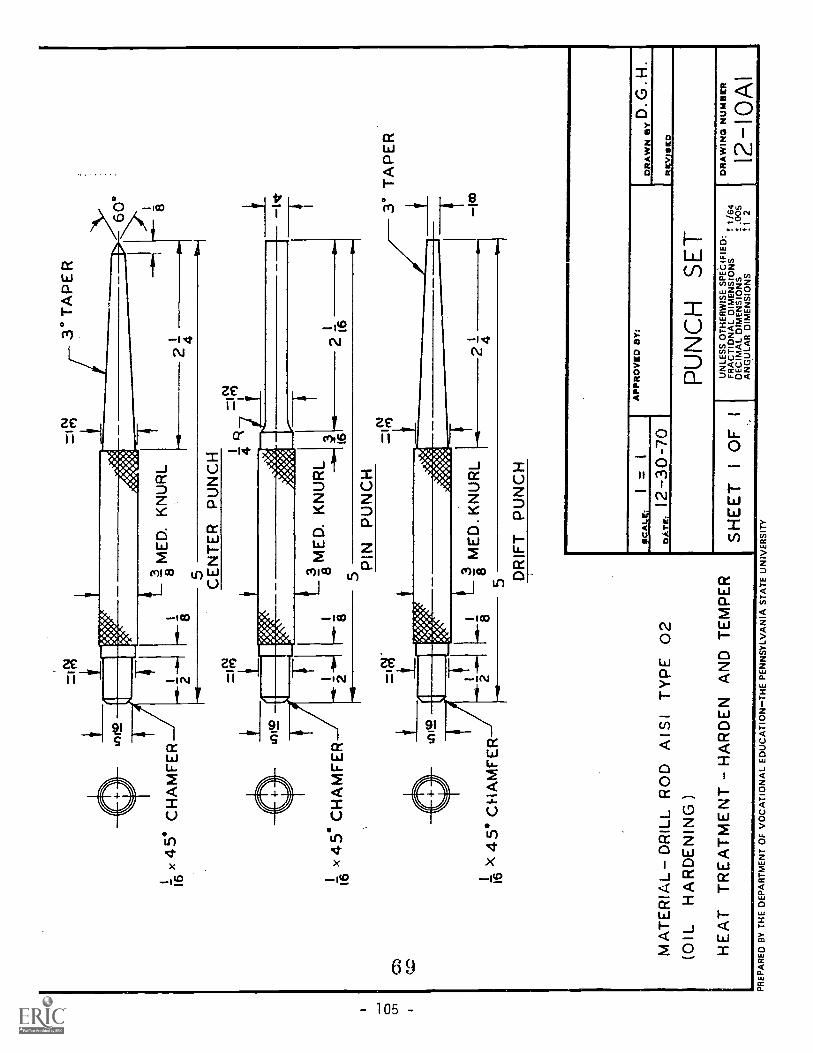
Ix
45°
CH
AM
FE
R16
=.1
m
tniw
1 1-6
x45.
CH
AM
FE
R
=0;
43°
TA
PE
R
3-M
ED
"K
NU
RL
8 5 CE
NT
ER
PU
NC
H
24
zi%
LM
ED
. KN
UR
L
5
45°
CH
AM
FE
R
MA
TE
RIA
L- D
RIL
L R
OD
AI S
I TY
PE
02
(OIL
HA
RD
EN
ING
)
PIN
PU
NC
H
5
16
01.
2116
Rm
.
-3M
ED
. KN
UR
L8
24
DR
IFT
PU
NC
H
HE
AT
TR
EA
TM
EN
T H
AR
DE
N A
ND
TE
MP
ER
Syr
Vas
..
3° T
AP
ER
1w
SC
ALE
:=
1
12-3
0-70
AP
PR
OV
ED
Ern
DR
AW
N B
YD
. G.H
.
RE
VIS
ED
PU
NC
H S
ET
SH
EE
TI
OF
IU
NLE
SS
OT
HE
RW
ISE
SP
EC
IFIE
D:
FR
AC
TIO
NA
L D
IME
NS
ION
S1:
1/6
4D
EC
IMA
L D
IME
NS
ION
St .
005
AN
GU
LAR
DIM
EN
SIO
NS
II 2
DR
AW
ING
NU
MB
ER
12-1
0A1
PR
EP
AR
ED
BY
TH
E D
EP
AR
TM
EN
T O
F V
OC
AT
ION
AL
ED
UC
AT
ION
-TH
E P
EN
NS
YLV
AN
IA S
TA
TE
UN
IVE
RS
ITY

JOB SHEET
Job. No. J-13-10-24 Drawing No. 13-10A1
COLD CHISEL
EQUIPMENT: Shaper, lathe, heat treating furnace, power cutoff saw, and benchgrinder.
TOOLS: tongsscriberfile card
SAFETY PRECAUTIONS:
layout dye6" steel ruleasbestos gloves
10" mill filestraight toolholderright hand facing tool
1. Stop movement of machine before making adjustments.2. Always check speed control levers before starting machine.3. Check all dimensions carefully to limit material loss.4. Operate no equipment without authority to do so.
PROCEDURE:
1. Select correct octagonal tool steel.2. Cut stock to length on power cutoff saw.3. Mount work piece in lathe and face one end.4. Turn 45° chamfer as per print.5. Layout for taper.6. Mount work piece to layout in shaper (refer to Operation Sheet Nos.
SL-5-1, 2, 3, 4, and 5).7. Shape taper to layout allowing 1/64" for finishing.8. Repeat steps 6 and 7 for opposite side of the chisel.9. Draw file to layout lines.
10. Draw file all sides of octagon.11. Heat treat.12. Hand grind 60° to 70° cutting edge.
NOTE: The cutting edge should be slightly curved i:Istead ofstraight across.
13. Inspect as per print:-

CD
tC1
\GR
IND
CU
TT
ING
ED
GE
TO
SLI
GH
T R
AD
IUS
Mir
y)
-Sr
MA
XIM
UM
32
22
MA
TE
RIA
L -
TO
OL
ST
EE
L A
IS1
TY
PE
WI
(WA
TE
R H
AR
DE
NIN
G)
HE
AT
TR
EA
TM
EN
T -
HA
RD
EN
AN
D T
EM
PE
R
x 45
CH
AM
FE
R
3 4
DA
TE
:12
-30-
70-1
SC
ALE
:=
AP
PR
OV
ED
BY
tD
RA
WN
BY
D.G
.H.
RE
VIS
ED
CO
LD C
HIS
EL
SH
EE
TI
OF
IU
NLE
SS
OT
HE
RW
ISE
SP
EC
IHE
D:
1164
DR
AW
ING
NU
MB
ER
FR
AC
TIO
NA
L D
IME
NS
ION
SD
EC
IMA
L D
IME
NS
ION
S.0
0513
- IO
AI
AN
GU
LAR
DIM
EN
SIO
NS
± 1
2
PR
EP
AR
ED
BY
TH
E D
EP
AR
TM
EN
T O
F V
OC
AT
ION
AL
ED
UC
AT
ION
-TH
E P
EN
NS
YLV
AN
IA S
TA
TE
UN
IVE
RS
ITY

HA
ND
LE P
LUG
DW
G.N
O. 1
4- I0
A3
HA
MM
ER
HA
ND
LED
WG
. NO
. 14-
10A
3
HA
MM
ER
HE
AD
DW
G. N
O. 1
4-10
A 2
1
SH
EE
T 1
0F 3
SC
ALE
;T
AP
PR
OV
ED
BY
:D
RA
WN
By
D. G
. H.
DA
TE
:8-
12-7
0R
EV
ISE
D
BA
LL P
EE
N H
AM
ME
R- A
SS
EM
BLY
PR
EP
AR
ED
BY
TH
E D
EP
AR
TM
EN
T O
F V
OC
AT
ION
AL
ED
UC
AT
ION
-TH
E P
EN
NS
YLV
AN
IAS
TA
TE
UM
VE
RS
ITY
UN
LES
S O
TH
ER
WIS
E S
PE
CIF
IED
:F
RA
CT
ION
AL
DIM
EN
SID
NS
1/64
DE
CIM
AL
DIM
EN
SID
NS
I .00
5A
NG
ULA
R D
IME
NS
IDN
S±
1 2
DR
AW
ING
NU
MB
ER
14-1
0AI
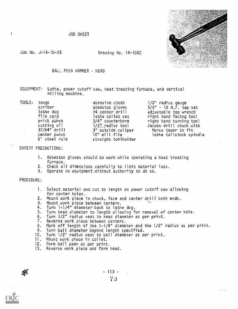
JOB SHEET
Job No. J-14-10-25 Drawing No. 14-10A2
BALL PEEN HAMMER HEAD
EQUIPMENT: Lathe, power cutoff saw, heat treating furnace, and verticalmilling machine.
TOOLS: tongsscriberlathe dogfile cardpria PUfichcutting oil37/64" drillcenter punch6" steel rule
SAFETY PRECAUTIONS:
abrasive clothasbestos gloves#4 center drilllathe collet set3/4" counterbore1/2."radius tool3" outside caliper10" mill filestraight toolholder
1/2" radius gauge5/8" - 18 N.F. tap setadjustable tap wrenchright hand facing toolright hand turning toolJacobs drill chuck with
Morse taper to fitlathe tailstock spindle
1. Asbestos gloves should be worn while operating a heat treatingfurnace.
2. Check all dimensions carefully to limit material loss.3. Operate no equipment without authority to do so.
PROCEDURE:
1. Select material and cut to length on power cutoff saw allowingfor center holes.
2. Mount work piece in chuck, face and center drill both ends.3. Mount work piece between centers.4. Turn 1-1/4" diameter back to lathe dog.5. Turn head diameter to length allowing for removal of center hole.6. Turn 1/2" radius next to head diameter as per print.7. Reverse work piece between centers.8. Mark off length of the 1-1/4" diameter and the 1/2" radius as per print.9. Turn ball diameter beyond length specified.
10. Turn 1/2" radius next to ball diameter as per print.11. Mount work piece in collet.12. Form ball peen as per print.13. Reverse work piece and form head.
- 113 -
7 3
Job No. J-14-10-25Page 2
14. Polish with abrasive cloth.15. Layout head for tapped hole and center punch.16. Mount work piece on vertical milling machine and pick up center.17. Drill, tap and counterbore as per print.18. Case harden.19. Repolish with abrasive cloth.20. Inspect as per print.
- 114 -
74
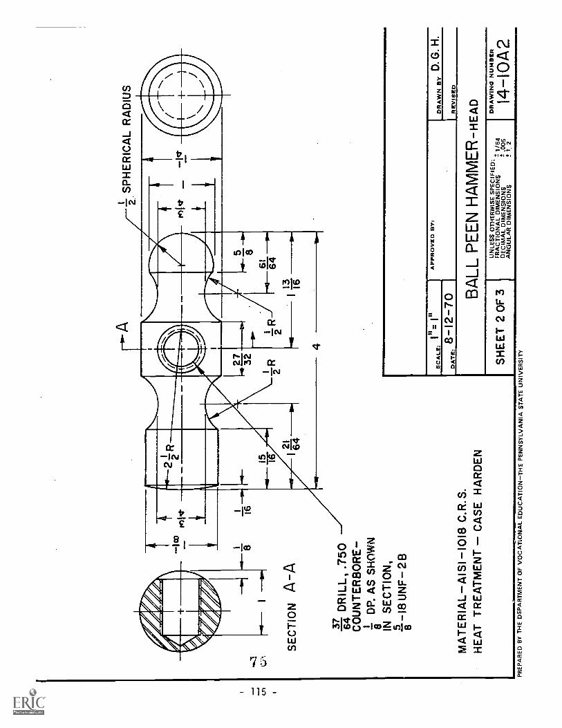
SP
HE
RIC
AL
RA
DIU
S2.
SE
CT
ION
AA
816
37D
RIL
L, .7
5064 C
OU
NT
ER
BO
RE
DP
. AS
SH
OW
N
IN S
EC
TIO
N,
18 U
NF
2 8
8
328
61 6421
1364
16
MA
TE
RIA
L A
ISI 1
018
C.R
.S.
HE
AT
TR
EA
TM
EN
TC
AS
E H
AR
DE
N
4
III
SC
ALE
:
DA
TE
:8
12-7
0A
PP
RO
VE
D B
Y:
DR
AW
N B
YD
. G. H
.
RE
VIS
ED
BA
LL P
EE
N H
AM
ME
R-H
EA
D
SH
EE
T 2
OF
3U
NLE
SS
OT
HE
RW
ISE
SP
EC
IFIE
D:
FR
AC
TIO
NA
L D
IME
NS
ION
S1/
64D
EC
IMA
L D
IME
NS
ION
S±
.005
AN
GU
LAR
DIM
EN
SIO
NS
t 1 2
DR
AW
ING
NU
MB
ER
14-I
0A2
PR
EP
AR
ED
BY
TH
E D
EP
AR
TM
EN
T O
F V
OC
AT
ION
AL
ED
UC
AT
ION
-TH
E P
EN
NS
YLV
AN
IA S
TA
TE
UN
IVE
RS
ITY

Job No. J-14-10-26
JOB SHEET
BALL PEEN HAMMER HANDLE
EQUIPMENT: Lathe and power cutoff saw.
TOOLS: file card3/4" reamerscrew-pitch gaugecenter gauge6" steel ruleknurling tool
SAFETY PRECAUTIONS:
#4 center drillabrasive cloth1/8" necking tool0-1" micrometer600 threading tool10" mill file
Drawing No. 14-10A3
left hand toolholderright hand facing toolright hand turning toolJacobs drill chuck withMorse taper to fitlathe tailstock taper
lathe collet set
1. Keep fingers away from knurling rolls.2. Check feed rate and direction of movement before putting tool to
work piece.3. Follow safety grooming precautions.
PROCEDURE:
1. Select 1" round aluminum and cut to rough length on power cutoffsaw
2. Mount work piece in chuck.3. Face and center drill both ends.4. Mount work piece between centers.5. Knurl as per print.6. Reverse handle and place soft metal under lock screw of the dog in
order to protect knurled surface.7. Turn .740 diameter.8. Turn thread diameter.9. Form undercut for thread relief.
10. Chamfer 300 to thread depth.11. Chase 5/8" 18 N.F. threads to fit head.12. Form radius next to threaded end to 1/2" diameter as shown on print.13. Turn taper using offset tailstock method.14. Reverse work piece and mount in collet.15. Drill and ream as per print.16. Polish machined surfaces with abrasive cloth.17. Inspect as per print.
117-
'7 6

JOB SHEET
Job No. J-14-10-27 Drawing No. 14-10A3
BALL PEEN HAMMER - HANDLE PLUG
EQUIPMENT: Lathe and power cutoff saw.
TOOLS: file card6" -4-ee1 rule
abi ...hie cloth
0-1" micrometer
SAFETY PRECAUTIONS:
lathe collet set10" mill file1/16" necking tool
left hand toolholderright hand facing toolright hand turning tool
1. Be careful to break all sharp edges prior to polishing withabrasive cloth.
2. Check all dimensions carefully to limit material loss.3. Operate no equipment without authority to do so.
PROCEDURE:
1. Select 1" round aluminum stock and cut to rough length on powercutoff saw.
2. Mount work piece in collet.3. Face work piece.4. Turn 3/4" diameter. (Note tolerance.)5. Turn 1/16" x 450 chamfer.6. Form 1/16" x 1/32" undercut.7. Reverse work piece in collet.8. Turn head diameter and radius as per print.9. Polish with abrasive cloth.
10. Press plug into handle.11. Inspect as per print.
-119-

3 16
DR
ILL,
6 D
EE
P64 .7
50 f.
.Sgg
g R
EA
M,1
DP
.
ME
DIU
M K
NU
RL
f7)
re)
53
3 16
43
416
U'C
UT
,D
8
3 16II
L316
r4
HA
ND
LE
SC
ALE
- i=
II
U C
UT
, -h
DP
.
HA
ND
LE P
LUG
SC
ALE
- I=
I
MA
TE
RIA
L -
ALU
MIN
UM
1R
.
cr 0
.0.
300
CH
AM
FE
RT
O D
EP
TH
OF
TH
RE
AD
SC
ALE
:A
S S
HO
WN
DA
TE
:8-
12-7
0A
PP
RO
VE
D B
Y:
DR
AW
N B
YD
.G. H
.
RE
VIS
ED
BA
LL P
EE
N H
AM
ME
R-H
AN
DLE
a H
AN
DLE
PLU
G
SH
EE
T 3
OF
3{-
--
UN
LES
S O
TH
ER
WIS
E S
PE
CIF
IED
:+
FR
AC
TIO
NA
L D
IME
NS
ION
S-
1 /6
4D
EC
IMA
L D
IME
NS
ION
S±
.005
AN
GU
LAR
DIM
EN
SIO
NS
t. 1
2
DR
AW
ING
NU
MB
ER
14-1
0A 3
PR
EP
AR
ED
BY
TH
E D
EP
AR
TM
EN
T O
F V
OC
AT
ION
AL
ED
UC
AT
ION
-TH
E P
EN
NS
YLV
AN
IA S
TA
TE
UN
IVE
RS
ITY

SW
IVE
LD
WG
. NO
. 15-
I0A
5
SLE
EV
ED
WG
. NO
. 15-
1043
SC
RE
WD
WG
. NO
. 15-
1044
BA
SE
DW
G, N
O.1
5-10
42
DA
TE
:
in=
Ill
11-7
-70
AP
PR
OV
ED
BY
:D
RA
WN
BY
D. G
. H.
RE
VIS
ED
JAC
K S
CR
EW
-Ass
Em
BLy
SH
EE
T 1
OF
5U
NLE
SS
OT
HE
RW
ISE
SP
EC
IFIE
D:
FR
AC
TIO
NA
L D
IME
NS
ION
S.1
1/6
4D
EC
IMA
L D
IME
NS
ION
St .
005
AN
GU
LAR
DIM
EN
SIO
NS
t 12
DR
AW
ING
NU
MB
ER
15-1
0A1
PR
EP
AR
ED
BY
TH
E D
EP
AR
TM
EN
T O
F V
OC
AT
ION
AL
ED
UC
AT
ION
-TH
E P
EN
NS
YLV
AN
IA S
TA
TE
UN
IVE
RS
ITY

JOB SHEET
Job No. J-15-10-28
JACK SCREW BASE
EQUIPMENT: Lathe and power cutoff saw.
Drawing No. 15-10A2
TOOLS: file card11/16" drill6". steel rule#3 center drill
SAFETY PRECAUTIONS:
10" mill file3/4"-16 N.F. tap setleft hand toolholderright hand facing tool
cutting oilJacobs drill chuck withMorse taper to fitlathe tailstock spindle
adjustable tap wrench
1. Never use power, when tapping on the lathe.2. Allow sufficient clearance between chuck and compound rest.
PROCEDURE:
1 Select hex. C.R. steel and cut two pieces to rough length on powercutoff saw.
2. Mount work piece in chuck.3. Face and center drill.4. Drill 11/16" hole.5. Chamfer 300 to thread depth to assist starting tap.6. Tap 3/4"-16 N.F. using tailstock center to support tap.7. Form 300 chamfer on one end.8. Reverse work piece in chuck.9. Face to length.
10. Chamfer internal thread 30° to thread depth.11. Remove all burrs.12. Inspect as per print.
NOTE: Same procedure will be used for second base.
- 125 -
SO

MA
TE
RIA
L -
AIS
I -10
18 C
.R.S
. HE
X S
TO
CK
ILD
RIL
L,-
16 U
NC
-38,
40
30 C
HF
R T
O D
EP
TH
OF
TH
D B
OT
H E
ND
S
SC
ALE
:21
1..
11
DA
TE
:9-
26-7
0A
PP
RO
VE
D B
Y:
IDR
AW
N B
YD
. G. H
.
RE
VIS
ED
SH
EE
T 2
OF
5
JAC
K S
CR
EW
-BA
SE
-U
NLI
.SS
OT
HE
RW
ISE
SP
EC
IFIE
D:,
FR
AI:T
ION
AL
DIM
EN
SIO
NS
1/64
DE
CIM
AL
DIM
EN
SIO
NS
t .00
5A
NG
ULA
R D
IME
NS
ION
S:F
. 1 2
DR
AW
ING
NU
MB
ER
15-1
0A 2
PR
EP
AR
ED
BY
TH
E D
EP
AR
TM
EN
T O
F V
OC
AT
ION
AL
ED
UC
AT
ION
-TH
E P
EN
NS
YLV
AN
IA S
TA
TE
UN
IVE
RS
ITY

Job No. 3-15-10-29
JOB SHEET
JACK SCREW - SLEEVE
EQUIPMENT: Lathe and power cutoff saw.
TOOLS: file cardcenter gaugescrew-pitch gauge6" steel rule#4 center drill"U" drill (.368)
SAFETY PRECAUTIONS:
10" mill file600 threading tool3/32" necking tooladjustable tap wrench7/16-14 N.C. tap setleft hand toolholder
Drawing No. 15-10A3
cutting oilright hand facing toolright hand turning toolJacobs drill chuck withMorse taper to fitlathe tailstock spindle
1. Be careful not to run the cutting tool in,to the chuck.2. Files must not be used on the lathe unless they are fitted with
handles.
PROCEDURE:
lect hex. C.R. steel and cut sufficient material on power cutoffsaw for two sleeves.
2. Mount work piece in chuck.3. Face end and center drill.4. Extend work piece 2" from face of chuck and support with tailstock
center.5. Turn 3/4" thread diameter as specified.6. Chamfer starting end of thread 300 to thread depth.
7. Form 3/32" undercut for thread relief.8. Chase 3/4-16 N.F. threads to fit base.9. Remove tailstock center.
10. Drill center hole with "U" drill.11. Tap 7/16"-14 N.C. using tailstock center to support tap.12. Chamfer internal thread 300 to thread depth.
13. Form radius on hex. portion next to undercut.14. Part to rough length.'15. Reverse work piece in chuck.16. Face to length.
17. Form 3/32" radius.
- 129 -
8 2,

Job No. J-15-10-29Page 2
18. Form radius on hex. portion.
19. Draw file flats on hexagon.20. Remove all burrs.21. Inspect as per print.
NOTE: Same procedure will be used for second sleeve.

If -1
6 U
NF
- 3A
, 30
CH
FR
TO
DE
PT
H O
F T
HD
BO
TH
pID
S
MA
TE
RIA
L -
AIS
1-10
18 C
.R.S
. HE
X S
TO
CK
U (
.368
)DR
ILL,
i.-14
UN
C-
3B,
30°
CH
FR
TO
DE
PT
H O
F T
HR
EA
DB
OT
H E
ND
S
SC
ALE
:
DA
TE
:11
-7-7
0
AP
PR
OV
ED
BY
:
.711
10i1
1.11
1101
90.
0.G
.H.
DR
AW
:u
RE
% O
F:,
JAC
K S
C,..
_-
SLE
EV
E
SH
EE
T 3
OF
5U
NLE
SS
OT
HE
RW
ISE
SP
EC
If 'E
D:
FR
AC
TIO
UA
L D
IME
NS
ION
"t 1
/64
DE
CIM
AL
DIM
EN
SIO
NS
t .00
5A
NG
ULA
R D
IME
NS
ION
S4-
12
DR
AW
ING
NU
MB
ER
15-n
A3
PR
EP
AR
ED
BY
TH
E D
EP
AR
TM
EN
T O
F V
OC
AT
ION
AL
ED
UC
AT
ION
-TH
E P
EN
NS
YLV
AN
IA S
TA
TE
UN
IVE
RS
ITY

Job No. J-15-10-30
JOB SHEET
JACK SCREW - SCREW
EQUIPMENT: Lathe and power cutoff saw.
TOOLS: file cardcutting oilcenter gaugescrew-pitch gauge6" steel rule#4 center drill
SAFETY PRECAUTIONS:
0-1" micrometer1/8" radius tool1/8" radius gauge600 threading tool10" mill file3/32" necking tool
Drawing No. 15-10A4
right hand facing toolright hand turning toolJacobs drill chuck withMorse taper to fitlathe tailstock spindle
parting blade and holderleft hand toolholder
1. Never shift tools in lathe tool post while machine is in operation.
2. Cover tool with a cloth to protect hands while making measurementson work piece.
PROCEDURE:
1. Select hex. C.R. steel and cut sufficient material on power cutoffsaw to make two screws.
2. Mount work piece in chutk.3. Face end and center drill.4. Extend work piece 2-5/8" from face and support end with tailstock
center.5. Turn 7/16" thread diameter 1-7/16" long.6. Chamfer starting end of thread 300 to thread depth.7. Form neck for thread relief.8. Chase 7/16"-14 N.C. threads sleeve.
9. Part to length.10. Mount work piece in collet.11. Form 9/32" ball end.12. Form 1/8" radius.13. Form 1/2" radius.14. Draw file hexagonal flats.15. Remove all burrs.16. Inspect as per print.
NOTE: Same procedure will be used for second screw.
7 133 -
8 :3

7U
NC
-3A
30°
CH
FR
TO
DE
PT
HO
F T
HD
BO
TH
EN
DS
MA
TE
RIA
L -A
ISI-
1018
C.R
.S. H
EX
ST
O K
PR
EP
AR
ED
BY
TH
E D
EP
AR
TM
EN
T
NO
.3 C
EN
TE
R D
RIL
L--3
DIA
.16
111
SC
ALE
:I
DA
TE
:11
-7-7
0
AP
PR
OV
ED
BY
:D
RA
WN
BY
D.G
.H.
RE
VIS
ED
JAC
K S
CR
EW
-SC
RE
W
SH
EE
T 4
OF
5U
NLE
SS
OT
HE
RW
ISE
SP
EC
IFIE
D:
FR
AC
TIO
NA
L D
IME
NS
ION
S±
116
4D
EC
IMA
L D
IME
NS
ION
S±
.005
AN
GU
LAR
DIM
EN
SIO
NS
± 1
2
OF
VO
CA
TIO
NA
L E
DU
CA
TIO
N-T
HE
PE
NN
SY
LVA
NIA
ST
AT
E U
NIV
ER
SIT
Y11
1.1M
11
DR
AW
ING
NU
MB
ER
15-1
0A4

Job No. J-15-10-31
JOB SHEET
JACK SCREW - SWIVEL
EQUIPMENT: Lathe and power cutoff saw.
TOOLS: file cardcutting oil9/32" drillhand hacksaw6" steel ruleabrasive cloth
SAFETY PRECAUTIONS:
#3 center drill0-1" micrometerball peen hammer1/8" radius tool1/8" radius gauge10" mill file
Drawing No. 15-10A5
left hand toolholderright hand facing toolright hand turning toolJacobs drill chuck with
Morse taper to fitlathe tailstock taper
1. Observe all shop safety rules.2. Always be aware of the location of the STOP button.
0ROCEDURE:
1. Select C.R. steel and cut two pieces to rough length on powercutoff saw.
2. Mount work piece in chuck.3. Face end and center drill.4. Drill 9/32" hole to receive ball end of screw.
5. Form 1/8" radii.6. Reverse work piece in chuck.7. Face to length.
8. Saw 8 slots in radius end of swivel as per print using handhacksaw.
9. Remove a.;10. Insert ball t,nd of screw into swivel and peen in place loosely so
that swivr:': rotate on ball end.!, Ir,pect 6:1 pLr print.
NOTE: Us7s Vvi same procedure for second work piece.

MA
TE
RIA
L -
AlS
1-10
18 C
.R.S
.
SC
ALE
:
DA
TE
:
2 =
III
9 -2
6-70
AP
PR
OV
E&
JY
:D
RA
WN
BY
D. G
. H.
RE
VIS
ED
JAC
K S
CR
EW
- SW
IVE
L
SH
EE
T 5
OF
5U
NLE
SS
DT
HE
RW
ISE
SP
EC
IFIE
D:
FR
AC
TIO
NA
L D
IME
NS
IDN
S1
/64
DE
CIM
AL
DIM
EN
SID
NS
± .0
05A
NG
ULA
R D
IME
NS
IDN
S±
12
DR
AW
ING
NU
MB
ER
I 5-
10 A
5P
RE
PA
RE
D B
Y T
HE
DE
PA
RT
ME
NT
OF
VD
CA
TIO
NA
L E
DU
CA
TID
N-T
HE
PE
NN
SY
LVA
NIA
ST
AT
E U
NIV
ER
SIT
Y

/HA
ND
LED
WG
. NO
. 16-
1043
HE
AD
DW
G. N
O. 1
6-10
42
'V
SC
ALE
:/2
DA
TE
:8-
14-7
0A
PP
RO
VE
D B
Y:
DR
AW
NB
yD
.G.H
RE
VIS
ED
ME
AT
TE
ND
ER
IZE
R- A
SS
EM
BLY
UN
LES
S O
TH
ER
WIS
E S
PE
CIF
IED
:F
RA
CT
ION
AL
DIM
EN
SIO
NS
DE
CIM
AL
DIM
EN
SIO
NS
! 1/6
4S
HE
ET
1 O
F 3
.005
DR
AIW
6N-G
:164
:EA
RI
AN
GU
LAR
DIM
EN
SIO
NS
12
PR
EP
AR
ED
BY
TH
E D
EP
AR
TM
EN
T O
F V
OC
AT
ION
AL
ED
UC
AT
ION
-TH
E P
EN
NS
YLV
AN
IA S
TA
TE
UN
IVE
RS
ITY

JOB SHEET
Job No. J-16-10-32 Drawing No. 16-10A2
MEAT'TENDERIZER HEAD
EQUIPMENT: Power cutoff saw, drill press, and shaper.
TOOLS: scriberfile cardlayout dyeprick punch
SAFETY PRECAUTIONS:
27/64" drillcenter punchlayout hammer
5/8" counterbore
10" mill file1/2"-13 N.C. tap setcombination square set
1. Never stand in fronc of a shaper while it is in motion.2. Do not allow excessive overhang of tc)lholder.3. Be careful not to get caught between the tool and the work piece.
PROCEDURE:
1. Select specified size of aluminum and cut to rough length on poweraltoff saw.
2. Mount work piece in shaper vise.3. Shape ends square and to required length.4. Re-.uve all burrs.5. Layout serration guide lines.6. Remount work piece i shaper vise..7. Shape str lY.;agserrations on one end.8. Shape cros 5,,irrations on opposite end.9. Layout locaion for tapped hole.
10. Drill hole 'or 1/2-13 N.C. tap.11. Counterbore hole as per print.12. Tap hole 1/2-13 N.F.13. Draw file all four sides.14. Inspect as per print.
- 143 7

0
MA
TE
RIA
L S
AE
ST
D. N
O.2
6 A
LUM
INU
M
CN
J
27 64D
RIL
L,
1-13
UN
C-2
13,
2 .625
CB
OR
E D
P.
SC
ALE
.
DA
TE
.
11=
in
8 13
70
AP
PR
OV
ED
BY
:D
RA
WN
BY
D. G
.H.
RE
VIS
ED
ME
AT
TE
ND
ER
IZE
R-H
EA
D
SH
EE
T 3
OF
3U
NLE
SS
OT
HE
RW
ISE
SP
EC
'7IE
D:
FR
AC
TIO
NA
L D
IME
NS
IOI.S
! 1/6
4D
EC
IMA
L D
IME
NS
ION
St .
005
AN
GU
LAR
DIM
EN
SIO
NS
!I 2
DR
AW
ING
NU
MB
ER
16-I
0A2
PR
EP
AR
ED
BY
TH
E D
EP
AR
TM
EN
T O
F V
OC
AT
ION
AL
ED
I CA
TIO
NT
HE
PE
NN
SY
LVA
NIA
ST
AT
E U
NIV
ER
SIT
Y

Job No. J-16-10-33
JOB SHEET
MEAT TENDERIZER - HANDLE
EQUIPMENT: Power cutoff saw and lathe.
TOOLS: file cardlathe dogcenter gaugescrew-pitch gaugeknurling toolabrasive cloth
SAFETY PRECAUTIONS:
#3 center drilllathe collet set10" mill file600 threading tool1/16" necking tool
Drawing No. 16-10A3
left hand toolholderright hand facing toolright hand turning toolJacobs drill chuck withMorse taper to fitlathe tailstock spindle
1. Keep cleaning and coolant brushes clear of work when knurling.2. Always be aware of the direction of travel and speed t the
carriage before engaging automatic feed.
PROCEDURE:
1. Select and cut on power cutoff saw the specified size of aluminumallowing material for center removal.
2. Mount work piece in lathe.3. Face and center drill each end.4. Mount work piece between centers.5. Turn 7/8" diameter to lathe dog.6. Knurl 7/8" diameter 4-3/4" long.7. Turn 5 grooves 1/16" wide by 1/16" deep.8. Reverse work piece.9. Turn .615" diameter 1-1/8" long.
10. Turn thread diameter.11. Chamfer 300 to thread depth.12. Form undercut for thread reli13. Chase 1/2-13 N.C. threads.14. Tu n tEaper using offset tailstock method (refer to Operation Sheet
No. SL-1-13).15. Turn 1/2" diameter between taper and .615" diameter.16. Mount work piece in collet, handle end exposed.17. Remove center at knurled eld of handle.
18. Form radius on end of handle.19. Polish with abrasive cloth.20. Inspect as per print.
- 147 -
)o

WD
16*
ygD
P.
ME
DIU
M K
NU
RL
1 8
u C
UT
xD
R
-13
UN
C-c
A
p-
MA
TE
RIA
L- S
AE
ST
D. N
O.2
6 A
LUM
INU
M
412
030
CH
AM
FE
RT
O D
EP
TH
OF
TH
RE
AD
SC
ALE
:1/
22
IS
I
DA
TE
-8-
14-7
0A
PP
RO
VE
D B
Y:
DR
AW
N B
YD
.G.H
.
RE
VIS
ED
ME
AT
TE
ND
ER
1ZE
R-H
AN
DLE
SH
EE
T 2
OF
3P
RE
PA
RE
D B
Y T
HE
DE
PA
RT
ME
NT
OF
VO
CA
TIO
NA
LE
DU
CA
TIO
N-T
HE
PE
NN
SY
LVA
NIA
ST
AT
E U
NIV
ER
SIT
Y
UN
LES
S O
TH
ER
WIS
E S
PE
CIF
IED
:F
RA
CT
ION
AL
DIM
EN
SID
NS
± 1
/64
DE
CIM
AL
DIM
EN
SIO
NS
.005
AN
GU
LAR
DIM
EN
SIO
NS
12
DR
AW
ING
NU
MB
ER
16-1
0A3

Job No. J-17-10-34
JOB SHEET
LATHE CENTERS
Drawing No. 17-10A1 Z.9"--A15g"
EQUIPMENT: Lathe, tool post grinder, heat treating furnace, and power cutoffsaw.
TOOLS: tongsscriberfile cardlathe doglayout dyecutting oilcenter gauge12" Steel rile
SAFETY PRECAUTIONS:
parting blade andholder
#3 center drillasbestos glovesabrasive cloth#2 Morse tapereddrill sleeve
1/16" necking tool
10" mill fileleft hand toolholderright hand facing toolright hand turning toolJacobs drill chuck 1.ith
Morse taper to fitlathe tailstock spindle
0-1" micrometer
1. When using tool post grinder make sure the work piece always turnsin the opposite direction to that of the grinding wheel at thepoint of contact.
2. Keep face away from opening when lighting heat treating furnace.
PROCEDURE:
1. Select drill rod and saw to rough length on power cut saw.
2. Mount work piece in lathe chuck.3. Face and center drill each end.4. Mount work piece between centers.5. Adjust taper attachment to turn a #2 Morse taper (refer to'Operation
Sheet_No. SL-1-27).6. Rough turn tanr.7. Test taper by fitting with a #2 Morse taper drill sleeve.8. Take second cut and test Refore. Repeat until the correct
taper is attained.9. Finishing turning taper, - ,olish with abrasive cloth.
10. Form groove as per print in one center for identification of hardness.11. Reverse work piece between centers.12. Finish turn taper on other end and polish with abrasive cloth.13. Set up lathe for straight turning.14. Undercut both ends for clearance at small end of taper and form
radius by filing.

Job No. 3-17-10-34Page 2
15. Layout location of 1/8" groove at the center of the stock.16. Mount one tapered end in spindle and part the centers.17. Adjust compound rest to turn center points.18. Turn angles on center points. Check accuracy of angle with center
gauge.
NOTE: Allow .010 for finish grinding 600 point.
19. Orden and temper center identified by groove.20. Set up tool post grinder (refer to Operation Sheet No. SL-1-28).21. Grind 60° points on both centers22. Inspect as per print.
152 -

NO
. 3 C
EN
TE
R D
RIL
L- a
D.
BO
TH
EN
DS
33
4
- -
- -
- -
- - -
_I
I
II
I
Iii
II
I
33 4
33 4
MO
RS
E T
AP
ER
NO
. 2
MA
TE
RIA
L -
DR
ILL
RO
D A
I SI T
YP
E 0
2(
OIL
HA
RD
EN
ING
)H
EA
T T
RE
AT
ME
NT
- H
AR
DE
N A
ND
TE
MP
ER
GR
OO
VE
1LY
EN
TIF
IES
HA
RD
EN
ED
CE
NT
ER
, AM
. 419
1,11
07.,1
7:A
MM
O
SC
ALE
:=
I
DA
TE
;12
-30
-70
AP
PR
OV
ED
BY
:D
RA
WN
BY
D.G
. H.
R E
V' ,
JED
LAT
HE
CE
NT
ER
S
SH
EE
TP
RE
PA
RE
D B
Y T
HE
DE
PA
RT
ME
NT
OF
VO
CA
TIO
NA
L E
DU
CA
TIO
N-T
HE
PE
NN
SY
LVA
NIA
ST
AT
E U
NIV
ER
SIT
YO
FLi I
UN
LES
S O
TH
ER
WIS
E S
PE
CIF
IED
:F
RA
CT
ION
AL
DIM
EN
SIO
NS
1/64
DE
CIM
AL
DIM
EN
SIO
NS
tA
NG
ULA
R D
IME
NS
ION
S!1
2
DR
AW
ING
NU
MB
ER
17-
10A
1

PLU
GN
OS
ED
WG
. NO
. 18-
I0A
2D
WG
. NO
. 18-
10A
2
411M
1.11
111.
1=11
h=11
1-
Aik
/A7-
774-
70
II",
NIP
AA
rArA
nt_.
:106
`,IM
II,W
,41l
fPIN
trA
M,S
oOre
wl.d
ar
BO
DY
DW
G. N
O. 1
8 -I
0A4
PO
INT
DW
G. N
O. 1
8-10
43
SC
ALE
:D
RA
WN
BY
D. G
. H.
DA
TE
:11
-14-
70
SH
EE
T 1
OF
4P
RE
PA
RE
D B
Y T
HE
DE
PA
RT
ME
NT
OF
VO
CA
TIO
NA
LE
DU
CA
TIO
NT
HE
PE
NN
SY
LVA
NIA
ST
AT
E U
NIV
ER
SIT
Y
UN
LES
S O
TH
ER
WIS
E S
PE
CIF
IED
:F
RA
CT
ION
AL
DIM
EN
SIO
NS
± 1
/64
DE
CIM
AL
DIM
EN
SIO
NS
± .0
05A
NG
ULA
R D
IME
NS
ION
S±
1 2
DR
AW
ING
NU
MB
ER
18-1
0AI

MB SHEET
Job No. J-18-10-35
SCRIBER - NOSE
EQUIPMENT: Lathe
TOOLS: file card"I" drill (.272)1/8" reamer7/64" drillparting bladeand holder
knurling tool
SAFETY PRECAUTIONS:
Drawing No. 18-10A2
6" steel rule600 countersink"I" flat bottomdrill (.272)
#2 center drilllathe collet set.5/16"-24 N.F. tap set
10" mill fileleft hand toolholderright hand facing toolright hand turning toolJacobs drill chuck withMorse taper to fit:lathe tailstock spindle
1. Never try to remove chips from drills with your fingers.2.. Reduce spindle speed by 1/3 when reaming.
PROCEDURE:
1. Mount a length of 3/8" C.R. steel in chuck.2. Face end and center drill.3. Support material with center and knurl.4. Drill 7/64" hole 3/4" deep.5. Drill "I" hole 5/16" deep measuring from the pc;t of the drill.6. Size hole with "I" flat bottom drill to depth as per ptiirt.7. Countersink 7/64" dia. hole 1/32" x 600 as per print. (Use #2
center drill.)8. Tap hole with 5/16"-24 N.F. bottom tap (refer to Operation Sheet No.
SL-1-21).9. Ream 7/64" hole with 1/8" reamer.
NOTE: Always use lubricant when reaming.
10. Part work piece allowing 1/64" to face.11. Mount work piece in collet and face.12. Set compound rest to 15° and turn taper.13. Break all sharp edges.14. Inspect as per print.
- 157 -
9 8

Job No. J-18-10-36
EQUIPMENT: Lathe
TOOLS: file cardcutting oilhand hacksaw6" steel rule
SAFETY PRECAUTIONS:
JOB SHEET
SCRIBER - PLUG
abrasive cloth0-1" micrometer10" mill file7/32" radius gauge
Drawing N . 18-10A2
left hand toolholderright hand facing toolright hand turning tool
I. It is dangerous practice to leave a chuck wrench in the chuck--even for a moment.
2. Be sure there is ample clearance for cutting operations thatrequire working close to the chuck.
PROCEDURE:
1. Mount a length of 3/8" C.R. steel in chuck and face end.2. Turn 5/16" diameter for press fit in scriber body. NOTE .TOLERANCE!3. Turn 1/16" x 450 chamfer on end to facilitate pressing.4. Remove all burrs and cut to rough length with hand hacksaw.5. Reverse work piece in chuck and turn radius according to print.6. Polish with abrasive 'cloth.7. Inspect as per print.
- 159 -
9 9

LEA
D D
RIL
L,I(
.272
) D
RIL
L- g
- D
RW
ITH
FLE
AT
BO
TT
OM
,D
RIL
L, a
t -24
UN
F-
3B-t
-1 D
P.
ME
DIU
MK
NU
RL
ZC
ZZ
Z:7
Ai"
7
MIM
E71
F.10
;7.1
.17.
177G
,
47
23 32
#0
15
NO
SE
+.0
0l.1
25-.
000
MA
TE
RIA
L- N
OS
E-
AIS
I-10
18 C
.R.S
.-
PLU
G-
AIS
I-10
18C
.R.S
. HE
X S
TO
CK
7
PLU
G
SC
ALE
:=
II
DA
TE
:11
-13-
70I..
......
.
AP
PR
OV
ED
BY
:D
RA
WN
BY
D.G
.H.
RE
VIS
ED
SC
RIB
ER
- DE
TA
ILS
SH
EE
T 2
OF
4U
NLE
SS
OT
HE
RW
ISE
SP
EC
IFIE
D:
FR
AC
TIO
NA
L D
IME
NS
ION
St 1
/64
DE
CIM
AL
DIM
EN
SIO
NS
t .00
5A
NG
ULA
R D
IME
NS
ION
St 1
2
DR
AW
ING
NU
MB
ER
18-1
042
PR
EP
AR
ED
BY
TH
E D
EP
AR
TM
EN
T O
F V
OC
AT
ION
AL
ED
UC
AT
ION
-TH
E P
EN
NS
YLV
AN
IA S
TA
TE
UN
IVE
RS
ITY

Job.No. 3-18-10-37
EQUIPMENT: Lathe
TOOLS: tongscutting oil6" steel rulehand hacksawabrasive clothasbestos gloves
SAFETY PRECAUTIONS:
JOB SHEET
SCRIBER - POINT
#2 center drill0-1" micrometerlathe collet set6" mill fileleft hand tcolholder
Drawing No. 18-10A3
right hand facing toolright hand turning toolJacobs drill chuck withMorse taper to fitlathe tailstock spindle
1. It is unsafe to have small diameter work extend more than an inchor two from the chuck or collet unless it is supported by thetailstock center.
2. Keep file clear of collets and chuck jaws.
PROCEDURE:
1. Mount 3/16" drill rod in ccllet, face, and center drill.2. Extend material to 2-1/4" and support with center.3. Turn 1/8" diameter and 600 angle.4. Adjust compound rest to turn 5° angle.5. Rough turn 5° angle.6. Saw off center with hand hacksaw.7. Finish file 5° angle.8. Polish with abrasive cloth.9. Revers.2 work piece in collet.
10. Saw to length.11. Turn 60° angle on end.12. Heat treat as per print.13. Repolish with abrasive cloth.14. Inspect as per print.

4111
t-L
MA
TE
RIA
L -
DR
ILL
RO
DA
ISI T
YP
E 0
2
AP
PR
OV
ED
SY
:S
CA
LE:
DA
TE
:11
-13-
70I..
.12R
AW
N B
YD
. G. H
.
RE
VIS
ED
SC
RIB
ER
- PO
INT
SH
EE
T 3
OF
4U
NLE
SS
OT
HE
RW
ISE
SP
EC
IFIE
D:
FR
AC
TIO
NA
L D
IME
NS
ION
SL
1/64
DE
CIM
AL
DIM
EN
SIO
NS
t .00
5A
NG
ULA
R D
IME
NS
ION
St1
2
DR
AW
ING
NU
MB
ER
18-1
0A3
PR
EP
AR
ED
BY
TH
E D
EP
AR
TM
EN
T O
F V
OC
AT
ION
AL
ED
UC
AT
ION
-TH
E P
EN
NS
YLV
AN
IA S
TA
TE
UN
IVE
RS
ITY

Job No. J-18-10-38
EQUIPMENT: Lathe
TOOLS: file card1/8" drillcutting oilhand hacksaw5/16" reamer19/64" drillscrew-pitch gaugecenter gauge
SAFETY PRECAUTIONS:
JOB SHEET
SCRIBER - BODY
6" steel ruleknurling tool#3 center drill600 countersinkabrasive cloth0-1" micrometer600 threading tool10" mill -ffle
Drawing No. 18-10A4
3/32" necking toolleft hand toolholderright hand facing toolright haild turning toolJacobs drill chuck with
Morse taper to fitlathe tailstock spindle
1. Always make sure your work is mounted securely in the chuck or collet.2. Do not put excessive pressure on work piece with tailstock center.
PROCEDURE:
1. Select and cut 3/8" C.R. steel with hand hacksaw.2. Mount work piece in chuck.3. Face and center drill one end.4. Support end with center.5. Knurl as per print.6. Turn 5/16" thread diameter.7. Chamfer 300 to thread depth.S. Form neck at shoulder end of thread diameter.9. Chase 5/16"-24 N.F. thread to fit scriber nose.
10. Drill 1/8" hole through work piece.11. Countersink 1/8" hole to 5/32" diameter with 60° countersink12. Reverse work piece in chuck.13. Face to length.14. Drill 19/64" hole.15. Ream hole with 5/16" reamer as per print.
NOTE: Keep the reamer lubricated.
16. Polish smooth surfaces with abrasive cloth.17. Inspect as per print.
- 167
103

_aD
RIL
L-2
5D
P.
\+
.000
5-1 - .0
000
iR
EA
M .3
122
DR
4--
ME
DIU
M K
NU
RL
5 jg -
24 U
NF
- 2A
30 C
HF
R T
O D
EP
TH
OF
TH
RE
AD
BO
TH
EN
DS
MA
TE
RIA
L -
AIS
I -10
18C
.R.S
.
3 4
aD
RIL
L
600
C' S
INK
xD
.
pm.
2"-
I"S
CA
LP:
DA
TE
:11
-13-
70
AP
PR
OV
ED
BY
:D
RA
WN
BY
D.G
.H.
RE
VIS
ED
SC
RIB
ER
-BO
DY
SH
EE
T 4
OF
4U
NLE
SS
OT
HE
RW
ISE
SP
EC
IFIE
D:
FR
AC
TIO
NA
L D
IME
NS
ION
S±
1 /6
4D
EC
IMA
L D
IME
NS
ION
St .
005
AN
GU
LAR
DIM
EN
SIO
NS
± 1
2P
RE
PA
RE
D B
Y T
HE
DE
PA
RT
ME
NT
OF
VO
CA
TIO
NA
LE
DU
CA
TIO
N-T
HE
PE
NN
SY
LVA
NIA
ST
AT
E U
NIV
ER
SIT
Y
DR
AW
ING
NU
MB
ER
18-
10A
4

Job No. J-19-10-39
JOB SHEET
PLUMB BOB
Drawing No. 19-10A1
EQUIPMENT: Power cutoff saw, lathe, and drill press.
TOOLS: scriberfile cardlayout dyecutting oil3/16" drill3/32" drillprick punch
SAFETY PRECAUTIONS:
center punch6" steel rulelayout hammerabrasive cloth#2 center drill3/8" radius gauge10" mill file
1. Observe safety rules for machine tools.2. Be careful of Every move you make.
PROCEDURE:
left hand toolholderright hand facing toolright hand turning toolJacobs drill chuck withMorse taper to fitlathe tailstock spindle
1. Select and cut 3/4" hex C.R. steel on power cutoff saw.2. Mount work piece in chuck. -3. Face first end and center drill as per print.4. Support extended with center.5. Drill 3/32" hole.6. Turn 5/8" diameter and 3/8" radius.7. Turn 1/4" diameter and 3/8" radius.8. Polish machined areas with abrasive cloth.9. Reverse work piece in chuck.
10. Adjust compound rest to turn point.11. Turn point.12. POlish point with abrasive cloth.13. Layout location of 3/16" hole.14. Drill 3/16" hole15. Inspect as per print.

Lk)
8 IN
CH
TA
PE
RP
ER
FO
OT
MA
TE
RIA
L- A
ISI -
1018
C.R
.S.
4
3 yiD
RIL
L,60
° C
S'IC
,3
DIA
16
SC
ALE
.lu
=1"
DA
TE
:8
-13
-70
AP
PR
OV
ED
BY
:D
RA
WN
BY
RE
VIS
ED
PLU
MB
BO
BS
HE
ET
I O
FI
UN
LES
S O
TH
ER
WIS
E S
PE
CIF
IED
:±
1 /6
4F
RA
CT
ION
AL
DIM
EN
SIO
NS
DE
CIM
AL
DIM
EN
SIO
NS
± 0
05A
NG
ULA
R D
IME
NS
ION
S1
2
DR
AW
ING
NU
MB
ER
19-1
0AP
RE
PA
RE
D B
Y T
HE
DE
PA
RT
ME
NT
OF
VO
CA
TIO
NA
LE
DU
CA
TIO
N-T
HE
PE
NN
SY
LVA
NIA
ST
AT
E U
NIV
ER
SIT
Y

FLU
ST
ER
HD
. SC
R.
10-3
2 x
1/2
LG.
7S
PR
ING
ST
OC
K6
FLA
T W
AS
HE
R/3
2 I.D
.X1/
20.D
.)(
5D
OW
EL
PIN
1/16
DIA
. x 1
/2 L
G.
4C
AP
AIS
I -10
18 C
.R.S
.20
- I0
A5
3P
UN
CH
DR
ILL
RO
D2
0- 1
0A4
2B
AS
EA
ISI -
1018
C.R
.S.
20 -
10A
3B
OD
YA
ISI -
1018
C.R
.S.
20-1
0A2
DE
T.
QT
Y.
PA
RT
NA
ME
MA
TE
RIA
LS
HE
ET
NO
.
111=
11
SC
ALE
.
DA
TE
.11
14 7
0A
PP
RO
VE
D B
Y:
DR
AW
N B
YD
. G.H
.R
EV
ISE
D
PA
PE
R P
UN
CH
-AS
SE
MB
LY
SH
EE
T1
OF
5U
NLE
SS
OT
HE
RW
ISE
SP
EC
IFIE
D:
FR
AC
TIO
NA
L D
IME
NS
ION
St 1
/64
DE
CIM
AL
DIM
EN
SIO
NS
t .00
5A
NG
ULA
R D
I ME
NS
I ON
St I
2
DR
AW
ING
NU
MB
ER
RE
PA
RE
D B
Y T
HE
DE
PA
RT
ME
NT
OF
VO
CA
TIO
NA
LE
DU
CA
TIO
N-T
HE
PE
NN
SY
LVA
NIA
ST
AT
EU
NIV
ER
SIT
Y20
- IO
AI

JOB SHEET
Job No. J-20-10-40
PAPER PUNCH BODY
EQUIPMENT: Power c
FOOLS: scriber6" square3/4" drill1/4" drill1/2" drilllayout dyecutting oil
,AFETY PRECAUTIONS:
Drawing No. 20-10A2
utoff saw, vertical milling machine,
center punchlayout hammer6" steel rule82° countersink#4 center drill#21 drill (.159)11/16" radius gauge
and surface grinder.
1. Never carry a scriber in your pocket.2. Never strike a blow with a loose hammer head.
ROCEDURE:
10" mill file10-32 N.C. tap setadjustable tap wrench10" flat filefile cardprick punch
1. Select and cut material to rough length on power cutoff saw.2. Mount work piece in milling machine vise.3. Mill ends to length.4. Mount work piece on surface grinder.5. Grind top and bottom surfaces to remove imperfections.6. Layout work piece as per drawing.7. Remount work piece in milling machine vise.8. Mill out sectjons as per print.9. Position table for machining 7/8" hole.
NOTE: Be careful to remove end play in table positioning screws
10. Center drill and drill progressively using 1/4", 1/2", and 3/4"drills (refer to Operation Sheet No. SL-4-3).
11. Finish bore 7/8" diameter hole (refer to Operation Sheet No. SL-4-15).12. Rough file 11/16" radius.13. Finish radius by draw filing.14. Position table for drilling tapped holes. Begin with hole nearest
vertical or back edge.
NOTE: Remove end play from table screws.

Job No. J-20-10-40Page 2
15. Center drill and drill #21 hole.16. Countersink 82° x 7/32" diameter.17. Tap 10-32 N.C. thread using drill chuck to start tap straight.
Finish by hand.18. Position table for second hole by using graduated dial on taole
screw.
NOTE: Remove end play from table screws.
19. Repeat procedural steps 15, 16, and 17.20. Break all sharp edges.21. Inspect as per print.
- 178 -
109

R
15 -LIN
E D
RIL
L,1-
464 .2
50 L
INE
RE
AM
AF
TE
RA
SS
EM
BLY
WIT
H B
AS
E.
LAP
TO
FIT
PU
NC
H.
MA
TE
RIA
L -
AIS
I -10
18 C
.R.S
.
NO
. 21
(.15
9) D
RIL
L,*
DP
.,82
°C
'SK
., j D
IA.,
10-3
2 U
NF
- 2E
32
HO
LES
II11
SC
ALE
:II
DA
TE
:1
14-7
0A
PP
RO
VE
D B
Y:
DR
AW
N B
y
RE
VIS
ED
PA
PE
R P
UN
CH
-BO
DY
SH
EE
T2
OF
5U
NLE
SS
OT
HE
RW
ISE
SP
EC
IFIE
D:
FR
AC
TIO
NA
L D
IME
NS
ION
SD
EC
IMA
L D
IME
NS
ION
SA
NG
ULA
R D
IME
NS
ION
S
± 1
/64
I .00
5±
12
PR
EP
AR
ED
BY
TH
E D
EP
AR
TM
EN
T O
F V
OC
AT
ION
AL
ED
UC
AT
ION
-TH
E P
EN
NS
YLV
AN
IA S
TA
TE
UN
IVE
RS
ITY
DR
AW
ING
NU
MB
ER
20-1
0A2
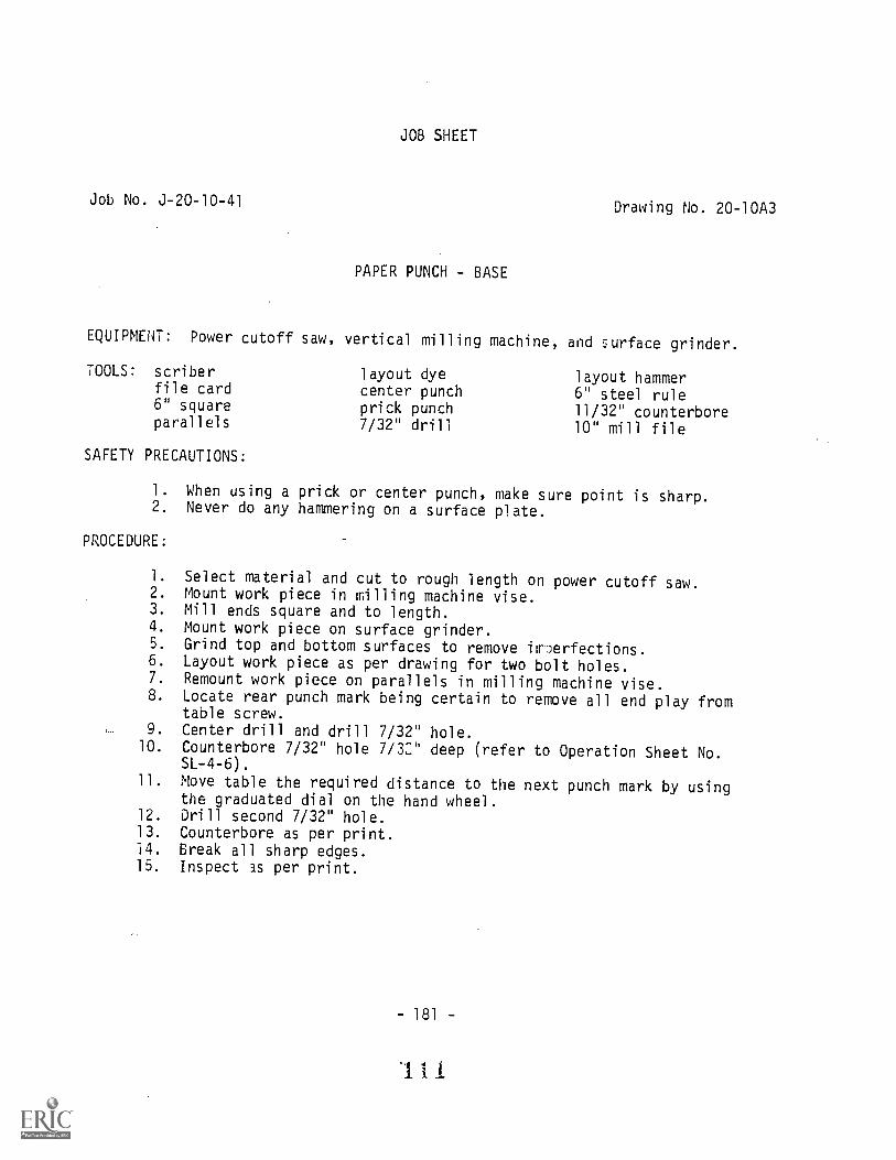
Job No. J-20-10-41
JOB SHEET
PAPER PUNCH - BASE
Drawing No. 20-10A3
EQUIPMENT: Power cutoff saw, vertical milling machine, and surface grinder.
TOOLS: scriberfile card6" squareparallels
SAFETY PRECAUTIONS:
layout dyecenter punchprick punch7/32" drill
layout hammer6" steel rule11/32" counterbore10" mill file
1. When using a prick or center punch, make sure point is sharp.2. Never do any hammering on a surface plate.
PROCEDURE:
1. Select material and cut to rough length on power cutoff saw.2. Mount work piece in Wling machine vise.3. Mill ends square and to length.4. Mount work piece on surface grinder.5. Grind top and bottom surfaces to remove irmerfections.6. Layout work piece as per drawing for two bolt holes.7. Remount work piece on parallels in milling machine vise.8. Locate rear punch mark being certain to remove all end play from
table screw.9. Center drill and drill 7/32" hole.
10. Counterbore 7/32" hole 7/32" deep (refer to Operation Sheet No.SL-4-6).
11. Move table the required distance to the next punch mark by usingthe graduated dial on the hand wheel.
12. Drill second 7/32" hole.13. Counterbore as per print.14. Break all sharp edges.15. Inspect 3S per print.
-181 -
111

I. IL b:J
15LI
NE
DR
ILL,
.250
LIN
E R
EA
MA
FT
ER
AS
SE
MB
LY W
iTH
BO
DY
.LA
P T
O F
IT P
UN
CH
.
MA
TE
RIA
L A
IS1
1018
C. R
.S.
7 t---
2 D
RIL
L, if
C'B
OR
E-1
'2 D
R2
HO
LES
lcu
1011
1111
1
SC
ALE
:I
2 I
AT
E11
-14-
70
AP
PR
OV
ED
ay:
, DR
AW
N
RE
V!!
D
PA
PE
R P
UN
CH
-BA
SE
SH
EE
T 3
OF
5U
NLE
SS
OT
HE
RW
ISE
SP
EC
IFIE
D:,
,F
RA
CT
ION
AL
DIM
EN
SIO
NS
1/64
DE
CIM
AL
DIM
EN
SIO
NS
.005
AN
GU
LAR
DIM
EN
SIO
NS
t 1 2
DR
AW
ING
NU
MB
ER
20-1
043
PR
EP
AR
ED
BY
TH
E D
EP
AR
TM
EN
T O
FV
OC
AT
ION
AL
ED
UC
AT
ION
-4H
E P
EN
NS
YLV
AN
IA S
TA
TE
UN
IVE
RS
ITY

Job No. 3-20-10-42
JOB SHEET
PAPER PUNCH - PUNCH
EQUIPMENT: Lathe, heat treating furnace, and drill press.
TOOLS: tongslayout dye1/16" drillprick punchcutting oilcenter punchcenter gauge
SAFETY PRECAUTIONS:
screw-pitch gaugehand hacksaw6" steel rulelayout hammerabrasive clothasbestos gloves#0 center drill
Drawing No. 20-10A4
lathe collet set3/16" radius gauge600 threading tool3/16" radius toolleft hand toolholderright hand facing tool10" mill file
1. Make sure the collet and work are securely fastened.2. Avoid excessive overhang witn tool and toolholder.
PROCEDURE:
1. Select and cut drill rod to length with hand hacksaw.2. Mount work piece in collet and extend approximately 1/2".3. Face end and chamfer 1/16" x 450 .
4. Chase 1/4-20 N.C. thread to length. Fit to zap.5. Reverse work piece in collet.6. Form 3/16" concave radius.7. Layout location of,1/16" hole.8. Center drill and drill 1/16" hole.9. Polish with abrasive cloth.
10. Heat treat.11. Repolish with abrasive cloth.12. Inspect as per print.
- 185 -
1 1 :3

R16
1616
DIA
. TO
FIT
- D
IA. X
4 P
IN2
LOC
AT
E A
T A
SS
EM
BLY
8
MA
TE
RIA
L -D
RIL
L R
OD
AIS
IT
YP
E 0
2H
EA
T T
RE
AT
ME
NT
-H
AR
DE
N A
ND
TE
MP
ER
52
e
UN
C 2
A
CH
AM
FE
R16
TO
DE
PT
H O
FT
HR
EA
D
SC
ALE
:=
II
DA
TE
:11
-14-
70A
PP
RO
VE
D B
Y:
DR
AW
N B
Y
RE
VIS
ED
PA
PE
R P
UN
CH
-PU
NC
H
SH
EE
T 4
OF
5U
NLE
SS
OT
HE
RW
ISE
SP
EC
IFIE
D:
FR
AC
TIO
NA
L D
IME
NS
ION
St1
164
DE
CIM
AL
DIM
EN
SIO
NS
AN
GU
LAR
DIM
EN
SIO
NS
-± 1
2
DR
AW
ING
NU
MB
ER
20-1
044
PR
EP
AR
ED
BY
TH
E D
EP
AR
TM
EN
T O
F V
OC
AT
ION
AL
ED
UC
AT
ION
-TH
E P
EN
NS
YLV
AN
IA S
TA
TE
UN
IVE
RS
ITY

Job No. J-20-10-43
JOB SHEET
PAPER PUNCH - CAP
EQUIPMENT: Power cutoff saw and lathe.
TOOLS: file cardcutting oil6" steel ruleabrasive cloth#7 drill (.201)#4 center drill
SAFETY PRECAUTIONS:
1/4-20 N.C. tap3/16" radius gauge10" mill file1/16" radius gaugeleft hand toolholder
Drawing No. 20-101\6
right hand facing toolright hand turning toolJacobs drill chuck withMorse taper to fitlathe tailstock spindl(
1. Always make certain your work is held securely when using chicksor collets,
2. Provide sufficient clearance between compound rest and chuck.
PROCEDURE:
I. Select and cut material 3/4" long on power cutoff saw.Mount work piece in chuck.
. Face end and center drill.4. Drill #7 drill as per print.5. Start tap, supported by center in tailstock.6. Finish tapping by hand.7. Turn 7116" diameter.8. Turn 1/16" radius.9. Reverse work piece in chuck.
10. Face to length.11. Turn 3/16" radius.12. Break all sharp edges.13. Polish with abrasive cloth.14. Inspect as per print.
- 189-
11 0

NO
.7 (
.201
) D
RIL
L,D
P.
- 20
UN
C-
28,1
5-4
DR
4
MA
TE
RIA
L -
AIS
1 -
1018
C.R
.S.
.37.
4747
....'"
417.
711N
I.,
r ,4:
0b
EIC
AL
n:t
DA
TE
.
AP
PR
OV
iED
BY
:
SH
EE
T 5
0F 5
1
PA
PE
R P
UN
CH
-cA
pU
NLE
SS
OT
HE
RW
ISE
SP
EC
IFIE
D:
FR
AC
TIO
NA
L D
IME
NS
ION
S1
1/64
DE
CIM
AL
DIM
EN
SIO
NS
± .0
05A
NG
ULA
R D
IME
NS
ION
St1
2P
RE
PA
RE
D B
Y T
HE
DE
PA
RT
ME
NT
OF
VO
CA
TIO
NA
L E
DU
CA
TIO
NT
HE
PE
NN
SY
LVA
NIA
ST
AT
E U
NIV
ER
SIT
Y

Job No. J-20-10-44
JOB SHEET
ASSEMBLY OF PAPER PUNCH
EQUIPMENT: Vertical milling machine.
TOOLS: scriberlayout dye1/4" reamercutting oilprick punch
SAFETY PRECAUTIONS:
center punch15/64" drill6" steel rulecenter finderlayout hammer
Drawing No. 20-10A1
1/2" parallelsabrasive cloth#3 center drill11/32" counterbore
1. Remove all chips and burrs.2. Use care when polishing with abrasive cloth held in hand.
PROCEDURE:
1. Assemble body and base.2. Layout assembly as per Drawing No. 20-10A2 in order to machine
hole for punch.3. Prick punch.4. Mount assembly on milling machine table, using 1/2" parallels to
insure against table damage.5. Locate prick punch mark with center finder.6. Center drill prick punch mark.7. Drill 15/64" hole through entire assembly.8. Ream 1/4" hole (refer to Operation Sheet No. SL-4-7).9. Counterbore reamed hole from underside of base as per Drawing No.
20-10A3.10. Assemble cap with punch and check for fit with body and base.
Some polishing of punch may be required to insure a desireablefit.
11. Final inspection requires the addition of a spring over thepunch and pinned into place.
- 193 -
1 1 7
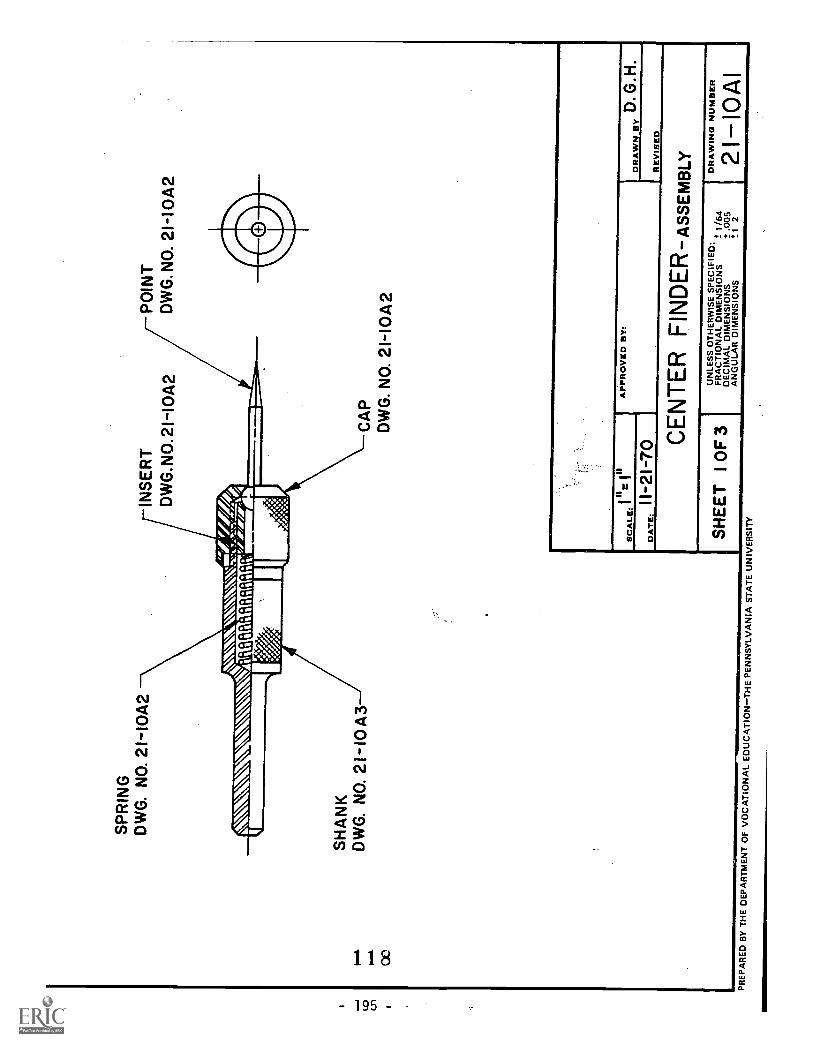
SP
RIN
GD
WG
. NO
. 21-
I0A
2IN
SE
RT
DW
G.N
0.21
-10A
2
\\\A
iin
un m
um.
p
PO
INT
DW
G. N
O. 2
1-I0
A2
SH
AN
KD
WG
. NO
. 21-
I0A
3C
AP
DW
G. N
O. 2
1-10
42
SC
ALE
:=
1'
DA
TE
:11
-21-
70
AP
PR
OV
ED
BY
:D
RA
WN
BY
D. G
.H.
RE
VIS
ED
CE
NT
ER
FIN
DE
R-A
ssE
pAeL
y
SH
EE
T 1
OF
3 I
UN
LES
S O
TH
ER
WIS
E S
PE
CIF
IED
:F
RA
CT
ION
AL
DIM
EN
SIO
NS
± 1
/64
DE
CIM
AL
DIM
EN
SIO
NS
t .00
5A
NG
ULA
R D
IME
NS
ION
St 1
2
DR
AW
ING
NU
MB
ER
21-1
0A1
PR
EP
AR
ED
BY
TH
E D
EP
AR
TM
EN
T O
F V
OC
AT
ION
AL
ED
UC
AT
ION
-TH
E P
EN
NS
YLV
AN
IA S
TA
TE
UN
IVE
RS
ITY

JOB SHEET
Job No. J-21-10-45 Drawing No. 21-10A2
CENTER FINDER - CAP
EQUIPMENT: Lathe and power cutoff saw.
TOOLS: file card1/4" drillcutting oil3/16" drill29/64" drillknurling tool6" steel rule
SAFETY PRECAUTIONS:
#2 center drill600 countersink0-1" micri:meterlathe collet set41/64" counterbore10" mill file
1/2-20 N.F. tap setleft hand toolholderadjustable tap wrenchright hand facing toolJacobs drill chuck withMorse taper to fitlathe tailstock spindle
1. Stop the machine before making measurements or adjustments.2. Do not run knurling tool into chuck jaws.
,ROCEDURE:
1. Select a short piece of required material and mount it in thelathe collet.
2. Face and center drill one end.3. Knurl 1" length.4. Drill 3/16" hole to sufficient depth.5. Drill 29/64" hole to specified depth and countersink.6. Tap 1/2"-20 N.F.
.
7. Counterbore 41/64" to specified depth.8. Turn 1/32" x 45° chamfer.9. Saw off cap to rough length on power cutoff saw.10: Remount work piece in collet.11. Face to length.12. Turn 1/8" x 45° chamfer and remove all burrs.13. Inspect as per print.
- 197 -
1 1 9

JOB SHEET
Job No. J-21-10-46Drawing No. 21-10A2
CENTER FINDER - BALL
EQUIPMENT: Lathe and heat treating furnace
TOOLS: tongs
cutting oil0-1" micrometer4'2 center drill
SAFETY PRECAUTIONS:
asbestos gloveslathe collet setii31 drill (.120)
abrasive cloth
Jacobs drill chuck withMorse taper to fitlathe tailstock spindle
straight toolholderappropriate tool bits
1. When discontinuing operations on a heat treatind furnace, alwaysturn off gas supply first.
PROCEDURE:
1. Select ball bearing as specified. Ball bearing can vary in sizeup to ten thousandths either larger of smaller.
2. Anneal the ball bearing in a non-oxidizing atmosphere to preventscaling of the ball surface (refer to Operation Sheet No. SL-8-3).
3. Select and turn a short length of rod to exactly the same diameteras the ball. This bar is to be mounted along with the ball to serveas a back-up to prevent the ball from slipping through the colletdue to the drilling pressure.
4. Mount ball and back-up bar in the collet and turn a small startingpoint for the center drill.
5. Center drill.6. Drill required hole to size and depth specified.7. Heat treat ball. Atmosphere surrounding ball should be controlled
to eliminate scaling.8. Remount ball in collet.9. Mount point in Jacobs chuck mounted in tailstock and press blunt
end into ball.10. Reverse work in collet and polish ball with abrasive cloth.11. Inspect as per print.
- 199-
120

JOB SHEET
Job No. J-21-10-47 Drawing No. 21-10A2
CENTER FINDER POINT
EQUIPMENT: Lathe and heat treating furnace.
TOOLS: tongsfile cardcutting oil
SAFETY PRECAUTIONS:
hand hacksaw6" steel ruleabrasive cloth
asbestos gloveslathe collet set10" mill file
1. Care must be taken when hand sawing small diameter material; sawclose to jaws at the bench vise.
PROCEDURE:
1. Select drill rod and cut to length using hand hacksaw.2. Mount work piece in collet and file point according to specifications.3. Use narrow strip of abrasive cloth to reduce diameter of blunt end
for press fit into ball.4. Polish with abrasive cloth.5. Heat treat.6. Inspect as per print.
-201 -
1 2 I

Job No. J-21-10-48
EQUIPMENT: Lathe
TOOLS: file card3/16" drillcutting oilhand hacksaw6" steel rule
SAFETY PRECAUTIONS:
JOB SHEET
CENTER FINDER - INSERT
600 countersink#2 center drill0-1" micrometer10" mill fileleft hand toolholder
Drawing No. 21-10A2
right hand facing toolJacobs drill chuck withMorse taper to fitlathe tailstock spindle
1. Check feed rates before turning on feed especially when workingnear the chuck.
2. Use extreme caution when filing near the chuck.
PROCEDURE:
1. Select required material and cut to rough length using hand hacksaw.2. Mount work piece in collet.3. Face and center drill.4. Drill 3/16" hole.5. Countersink as per print.6. Reverse work piece in collet.7. Face to length.8. Break all sharp edges.9. Inspect as per print.
- 203 -
1 :;I.! 2

% 'I
- 20
UN
F 2
BT
OD
EP
TH
S S
HO
WN
Iv
320
oC
,3
60S
INK
DIA
.
ter
en14
2ri
llV44
15 32
7
ox
45
C A
P
SP
RIN
G
HE
AT
TR
EA
TM
EN
T -
PO
INT
-H'D
N.
AN
D T
EM
PE
R-
BA
LL -
AN
NE
AL-
MA
CH
INE
-PA
CK
H!D
N. A
ND
TE
MP
ER
MA
TE
RIA
L -
CA
P -
AI S
F-1
018
C. R
.S
.
-15-
"I.E
1ijn
".1
DP
Toe
,-32 4/
DIA
. BA
LL B
RG
.
BA
LL
-Ico
15
I 6P
OIN
T
60°
C'S
INK
,
INS
ER
T
11.6
1111
1111
1111
IMM
INN
1I
SC
ALE
:
- P
OIN
T-
DR
ILL
RO
D -
AIS
I TY
PE
02I
DA
TE
:11
-21-
70-
SP
RIN
G -
MU
SIC
WIR
E-S
AE
-108
5-
INS
ER
T-
A1S
I -10
18 C
.R.S
.
AP
PR
OV
ED
BY
:
RE
1
CE
NT
ER
FIN
DE
R-D
ET
AIL
S
SH
EE
T 2
OF
3U
NLE
SS
OT
HE
RW
ISE
SP
EC
IFIE
D:
FR
AC
TIO
NA
L D
IME
NS
ION
S=
1 /6
4D
EC
IMA
L D
IME
NS
ION
S1.
005
AN
GU
LAR
DIM
EN
SIO
NS
2'1
2P
RE
PA
RE
D B
Y T
HE
DE
PA
RT
ME
NT
OF
VO
CA
TIO
NA
LE
DU
CA
TIO
N-T
HE
PE
NN
SY
LVA
NIA
ST
AT
E U
NIV
ER
SIT
Y

Job No. J-21-10-49
JOB SHEET
CENTER FINDER SHANK
EQUIPMENT: Lathe and power cutoff saw.
TOOLS: file card1/4" drillcutting oilscrew-pitch gaugeknurling tool6" steel ruleabrasive cloth
SAFETY PRECAUTIONS:
#2 center drilllathe collet set"U" drill (.368)1/8" radius tool10" mill file600 threading tool3/8" machine reamer
Drawing No. 21-10A3
left hand toolholderright hand facing toolright hand turning toolJacobs drill chuck with
Morse taper to fitlathe tailstock spindle
1. Always determine the direction of carriage movement before engagingthe automatic feed.
2. Do not use compressed air to remove chips from machine tools.
PROCEDURE:
1. Select required material and cut to rough length on power cutoff saw.2. Mount work piece in collet and face end.3. Turn 5/16" diameter.4. Form 1/8" radius.5. Turn 1/16" x 45° chamfer.6. Reverse work piece in collet.7. Face to length and center drill.8. Support work piece with center and knurl as specified.9. Turn thread diameter.
10. Chase 1/2-20 N.F. thread and fit to cap.11. Chamfer 300 to thread depth.12. Drill "U" hole to specified depth.13. Ream 3/8" hole 5/8" deep.14. Break all sharp edges.15. Polish with abrasive cloth.16. Inspect as per print.
207 -

- 20
UN
F -
2A
2
i30
CH
AM
FE
R T
OD
EP
TH
OF
TH
RE
AD
TA
-45
0,
37
44
33 8
MA
TE
RIA
L -
A IS
I-10
18 C
.R.S
.
U (
.368
)DR
ILLI
II D
P.
.375
+:r
ool R
EA
M,
DR
SC
ALE
:
DA
TE
:
IIz.
II
11-2
1-70
AP
PR
OV
ED
BY
:D
RA
WN
SY
D. G
.H.
RE
VIS
ED
CE
NT
ER
FIN
DE
R-s
HA
NK
SH
EE
T 3
OF
3U
NLE
SS
OT
HE
RW
ISE
SP
EC
IFIE
D:,
,F
RA
ClIO
NA
L D
IME
NS
ION
Sz
1/64
DE
CIM
AL
DIM
EN
SIO
NS
± .0
05A
NG
ULA
R D
IME
NS
ION
S±
12
DR
AW
ING
NU
MB
ER
21-1
0A3
PR
EP
AR
ED
F,'Y
TH
E D
EP
AR
TM
EN
T O
F V
OC
AT
ION
AL
ED
UC
AT
ION
-TH
EP
EN
NS
YLV
AN
IA S
TA
TE
UN
IVE
RS
ITY
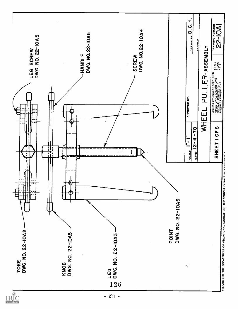
YO
KE
DW
G. N
O. 2
2-I0
A2
KN
OB
DW
G. N
O. 2
2-I0
A5
LEG
0.4
b.; D
WG
. NO
. 2 2
-I0
A3
PO
INT
DW
G. N
O. 2
2-I
0A6
LEG
SC
RE
WD
WG
. NO
. 22-
10A
5
HA
ND
LED
WG
. NO
. 22-
I0A
5
SC
RE
WD
WG
. NO
.22-
10A
4
II= in
scA
tx:
I
DA
TE
:12
-4 -
7-6-
1
AP
PR
OV
ED
BY
:D
RA
WN
BY
D. G
. H.
RE
VIS
ED
WH
EE
L P
ULL
ER
-Ass
Em
BLy
SH
EE
T 1
OF
6U
NLE
SS
OT
HE
RW
ISE
SP
EC
IFIE
D:
FR
AC
TIO
NA
L D
IME
NS
ION
S±
1/6
4D
EC
IMA
L D
IME
NS
ION
St.0
05A
NG
ULA
R D
IME
NS
ION
S1
2
DR
AW
ING
NU
MB
ER
22-1
01\1
PR
EP
AR
ED
BY
TH
E D
EP
AR
TM
EN
T O
F V
OC
AT
ION
AL
ED
UC
AT
ION
TH
EP
EN
INS
YI V
AN
IA C
TA
TF
tAllt
icO
CIT
y

JOB SHEET
Job No. J-22-10-50 Drawing No. 22-10A2
WHEEL PULLER - YOKE
EQUIPMENT: Lathe, vertical
TOOLS: scriberfile cardlayout dyecutting oilprick punch3/8" reamer11/32" drill37/64" drill
SAFETY PRECAUTIONS:
milling machine or shaper,
center punchlayout hammer12" steel rule#3 drill (.213)#4 center drill0-1" micrometer5/8"-18 N.F. tap1/4"-28 N.F. tap
and power cutoff saw.
1/8" radius tool1/8" radius gauge10" mill fileleft hand toolholderadjustable tap wrenchright hand facing toolJacobs drill chuck to fit
lathe tailstock spindle
1. Use a piece of cloth when handling milling cutters.2. Use a brush to remove accumulated chips, never bare hands or an
air hose.3. Make it a practice to know the location of the stop lever.
PROCEDURE:
1. Select the required material and cut to rough length.2. Mount work piece on milling machine table.3. Mill ends square and to length.4. Mount work piece in 4 jaw chuck.5. Face one side and turn boss as specified.6. Turn 1/8" radius.7. Center drill.8. Drill 37/64" hole.9. Reverse work piece in chuck centering the work piece with respect
to the drilled hole.10. Repeat steps 5 and 6.11. Tap 5/8"-18 N.F. thread.12. Layout work piece for slots and holes.13. Mount work piece on milling machine to mill slots.14. Mill slots (refer to Operation Sheet No. SL-4-5).15. Drill and tap 1/4"-28 N.F. holes.
NOTE: Finish all operations on each hole before proceeding to the next.
16. Drill and ream 3/8" holes.17. Break all sharp edges.18. Inspect as per print. 7
-213-
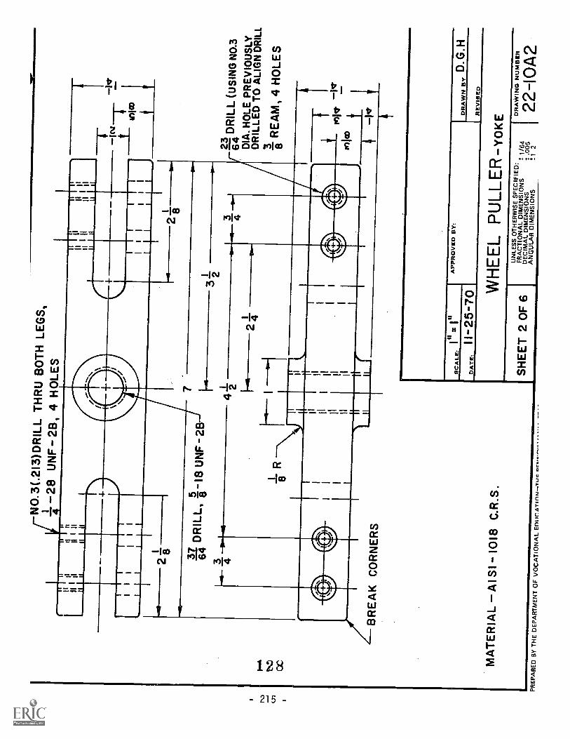
NO
.3(.
213)
DR
ILL
TH
RU
BO
TH
LE
GS
,4- -2
8 U
NF
-28
, 4 H
OLE
S
31D
RIL
L,5
-18
UN
F -
2B
64-d
3 423 gi
DR
ILL
(US
ING
NO
.3D
IA. H
OLE
PR
EV
IOU
SLY
DR
ILLE
D T
O A
LIG
N D
RIL
L3 8
RE
AM
, 4 H
OLE
S
BR
EA
K C
OR
NE
RS
MA
TE
RIA
L -A
I SI -
1018
C.R
.S.
SC
ALE
:
DA
TE
.II
25-7
0A
PP
RO
VE
D B
Y:
DR
AW
N B
YD
.G.H
RE
VIS
ED
WH
EE
L P
ULL
ER
-YoK
E
SH
EE
T 2
OF
6U
NLE
SS
OT
HE
RW
ISE
SP
EC
IFIE
D:
FR
AC
TIO
NA
L D
IME
NS
ION
S1/
64D
EC
IMA
L D
IME
NS
ION
S1
.005
AN
GU
LAR
DIM
EN
SIO
NS
!I 2
PR
EP
AR
ED
BY
TH
E D
EP
AR
TM
EN
T O
FV
OC
AT
ION
AL
ED
UrA
rinni
Tur
IDR
AW
ING
NU
MB
ER
22-1
0A2

JOB SHEET
Job No. J-22-10-51 Drawing No. 22-10A3
WHEEL PULLER - LEGS
EQUIPMENT: Vertical band saw or shaper, drill press, power cutoff saw, andsurface grinder.
TOOLS: scriberfile cardlayout dyeprick punch
SAFETY PRECAUTIONS:
center punch11/32" drilllayout hammer
6" steel rule10" mill file3/8" machine reamer
1. Handle band saw blades with extreme care. They are long andspringy and can uncoil at high speeds causing serious cuts.
PROCEDURE:
1. Select required material and cut to length on power cutoff saw.2. Layout work piece as per print.3. Drill 11/32" holes.4. Ream 3/8" holes.5. Shape or saw work pieces to layout lines.6. Grind and file radii on each leg.7. Surface grind all plane surfaces.8. Remove all burrs.9. Inspect as per print.
- 217 -
129

-IN
8
1
4-2
NO
TE
: 2 R
EQ
UIR
ED
MA
TE
RIA
L -
A 1
S1-
1018
C.R
. S.
-1-4
4 D
RIL
L,3 8
RE
AM
,2
HO
LES
2J- 1
6
§ 8
SC
ALE
:
DA
TE
:11
-25-
70
AP
PR
OV
ED
BY
:D
RA
WN
BY
D.G
.H.
RE
VIS
ED
WH
EE
L P
ULL
ER
-LE
G
SH
EE
T 3
OF
6U
NLE
SS
OT
HE
RW
ISE
SP
EC
IFIE
D:
FR
AC
TIO
NA
L D
IME
NS
ION
S. 1
/64
DE
CIM
AL
DIM
EN
SIO
NS
2: .0
05A
NG
ULA
R D
IME
NS
ION
S±
1 2
Yi:r
6473
PR
EP
AR
ED
BY
TH
E D
EP
AR
TM
EN
T O
F V
OC
AT
ION
AL
ED
UC
AT
ION
-TH
E P
EN
NS
YLV
AN
IA S
TA
TE
UN
IVE
RS
ITY

Job No. J-22-10-52
JOB SHEET
WHEEL PULLER - SCREW
EQUIPMENT: Lathe, drill press, and power cutoff saw.
TWLS: file cardlathe doglayout dye5/16" reamer9/32" drillcutting oilcenter gaugescrew-pitch gauge
center punchlayout hammer12" steel ruleabrasive cloth0-1" micrometer#3 center drilllathe collet set
Drawing No. 22-10A4
10" mill file-600 threading toolleft hand toolholderright hand facing toolright hand turning toolJacobs drill chuck withMorse taper to fitlathe tailstock spindle
SAFETY PRECAUTIONS:
1. Keep hands and clothing free of revolving lathe dog.
PROCEDURE:
1. Saw required hex. material and cut to.rough length on power cutoffsaw
2. Mount work piece in chuck.3. Face and center drill one end.4. Extend work piece 6" from jaws and support end with tailstock
center.5. Turn 5/8" thread diameter.6. Chase 5/8-18 N.F. thread as specified. Fit to yoke.7. Mount screw in collet.8. Crill 9/32" hole 5/8" deep.9. Ream 5/16" hole 1/2" deep.
10. Form 1/16" x 45° internal and external chamfers.11. Reverse work piece in collet.12. Face to length.la. File a slight radius on head.14. Polish with abrasive cloth.15. Layout 5/16" reamed hole.16. Drill 9/32" hole in head.17. Ream 5/16" hole.18. Remove all burrs.19. Inspect as per print.
- 221 -
131

ts: M
AT
ER
IAL
- A
ISI -
1018
C.R
.S. H
EX
. ST
OC
K
SC
ALE
:U
I-
I
DA
TE
:11
-2 6
-70
AP
PR
OV
ED
BY
:D
RA
WN
ByD
.G.H
.R
EV
ISE
D
WH
EE
L P
ULL
ER
-SC
RE
W
SH
EE
T 4
OF
6 I
UN
LES
S O
TH
ER
WIS
E S
PE
CIF
IED
:F
RA
CT
ION
AL
DIM
EN
SIO
NS
.t 1/
64D
EC
IMA
L D
IME
NS
ION
S.0
05A
NG
ULA
R D
IME
NS
ION
S11
2
DR
AW
ING
NU
MB
ER
22-I
0A4
PR
EP
AR
ED
BY
TH
E D
EP
AR
TM
EN
T O
FV
OC
AT
ION
AL
ED
UC
AT
ION
-TH
E P
EN
NS
YLV
AN
IAS
TA
TE
UN
IVE
RS
ITY
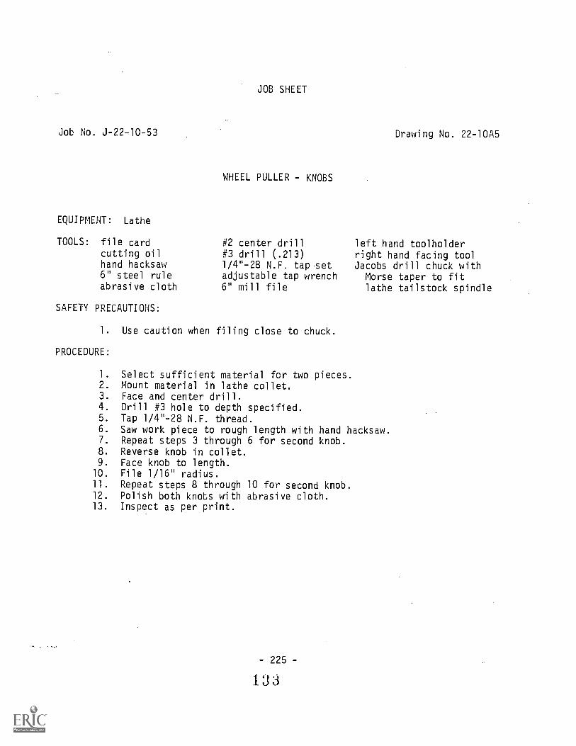
Job No. 3-22-10-53
EQUIPMENT: Lathe
TOOLS: file cardcutting oilhand hacksaw6" steel ruleabrasive cloth
JOB SHEET
WHEEL PULLER - KNOBS
#2 center drill#3 drill (.213)1/4-28 N.F. tap setadjustable tap wrench6" mill file
SAFETY PRECAUTIONS:
1. Use caution when filing close to chuck.
PROCEDURE:
Drawing No. 22-10A5
left hand toolholderright hand facing toolJacobs drill chuck withMorse taper to fitlathe tailstock spindle
1. Select sufficient material for two pieces.2. Mount material in lathe collet.3. Face and center drill.4. Drill #3 hole to depth specified.5. Tap 1/4"-28 N.F. thread.6. Saw work piece to rough length with hand hacksaw.7. Repeat steps 3 through 6 for second knob.8. Reverse knob in collet.9. Face knob to length.
10. File 1/16" radius.11. Repeat steps 8 through 10 for second knob.12. Polish both knobs with abrasive cloth.13. Inspect as per print.
225 -
133

Job No. 3-22-10-54
EQUIPMENT: Lathe
TOOLS: cutting oilhand hacksawscrew-pitch gaugecenter gauge12" steel rule
SAFETY PRECAUTIONS:
JOB SHEET
WHEEL PULLER HANDLE
abrasive cloth0-1" micrometer600 threading toollathe collet set
Drawing No. 22-10A5
1/16" necking tool10" mill fileleft hand toolholderright hand facihg toolright hand turning tool
1. Do not extend small diameter stock from chuck or collet too farwhen turning or threading.
PROCEDURE:
1. Select required material and cut to rough length using handhacksaw.
2. Mount work piece in collet and face.3. Turn 1/4" thread diameter.4. Form 1/16" undercut to 13/64" diameter.5. Chase 1/4-28 N.F. thread. Fit to knob.6. Chamfer 300 to thread depth.7. Reverse work piece in collet.8. Face piece to length.9. Repeat steps 3 through 6 for other end.
10. Remove all burrs.11. Polish with abrasive cloth.12. Inspect as per print.

Job No. 3-22-10-55
JOB SHEET
WHEEL PULLER - LEG SCREWS
EQUIPMENT: Lathe and power cutoff saw.
TOOLS: file cardcutting oilscrew-pitch gaugecenter gauge
6" steel rule0-1" micrometer60° threading tool10" mill file
Drawing No. 22-10A5
left hand toolholderright hand facing toolright hand turning tool
SAFETY PRECAUTIONS:
1. Be careful not to cut into lathe chuck with cutting tool. .
PROCEDURE:
1 Select required material and cut to rough length on power cutoffsaw. Two pieces required.2. Mount work piece in chuck and face.3. Turn .375 diameter.4. Turn 1/4" thread diameter.J. Form 1/16" undercuts as specified.6. Chase 1/4-28 N.F. thread.7. Chamfer 30° to thread depth.8. Reverse work piece in chuck.9. Face to length.
10. File chamfer on head.11. Remove all burrs.12. Inspect as per print.
NOTE: All the above procedure will be the same for the second screw.
229 -
1 3 5

30°C
HA
MF
ER
TO
DE
PT
H O
F T
HD
.-I
I16
DI A
U'C
UT
116
4 D
I
1111
NO
.3 (
.213
) xi
. DP
.U
NF
-28
x3
DP
8 KN
OB
MA
TE
RIA
L-
AlS
1-10
18 C
.R.S
.
7
8
HA
ND
LE
16
2
71-2
8 U
NF
-24
i-DIA
.,WA
SH
ER
FA
CE
DIA
32
--4/
3 D
IA6
1 2U
NF
-2A
LEG
SC
RE
W
SC
ALE
:
DA
TE
:I I
26-7
0A
PP
RO
VE
D B
ytD
RA
WN
BY
D.G
.H.
RE
VIS
ED
WH
EE
L P
ULL
ER
-DE
TA
ILS
SH
EE
T '5
OF
6U
NLE
SS
OT
HE
RW
ISE
SP
EC
IFIE
D:
FR
AC
TIO
NA
L D
IME
NS
ION
S11
/64
DE
CIM
AL
DIM
EN
SIO
NS
AN
GU
LAR
DIM
EN
SIO
NS
± 1
2
DR
AW
ING
NU
MB
ER
22-1
0A 5
PR
EP
AR
ED
BY
TH
E D
EP
AR
TM
EN
T O
F V
OC
AT
ION
AL
ED
UC
AT
ION
-TH
E P
EN
NS
YLV
AN
IA S
TA
TE
UN
IVE
RS
ITY

JOB SHEET
Job No. J-22-10-56 Drawing No. 22-10A6
WHEEL PULLER - POINT
EQUIPMENT: Lathe, heat treating furnace, and power cutoff saw.
TOOL,: file cardcutting oil6" steel ruleabrasive cloth
SAFETY PRECAUTIONS:
0-1" micrometerlathe collet set10" mill file
left hand toolholderright hand facing toolright hand turning tool
1. Never stand in front of a heat treating furnace when it is beingignited.
2. Work only in areas that are well ventilated.
PROCEDURE:
1. Select the required material and cut to length on power cutoff saw.2. Mount work piece in collet.3. Face one end.4. Turn .3135 diameter to length.5. Turn 1/32" x 450 chamfer.6. Reverse work piece in collet and face to length.7. Adjust compound rest to turn 900 point.8. Turn 900 point.9. Polish with abrasive cloth.
10. Harden and temper.11. Repolish with abrasive cloth.12. Assemble point to screw.13. Inspect as per print.
233 -
I 87

MA
TE
RIA
L -
AIS
1-10
18C
.R.S
.
15 16
SC
ALE
:2"
= 1
"D
AT
E:
ISH
EE
T 6
OF
6
11-2
6-70
AP
PR
OV
ED
BY
:D
RA
WN
BY
D.G
.H.
RE
VIS
ED
WH
EE
L P
UL
LE
R-P
oIN
TU
NLE
SS
OT
HE
RW
ISE
SP
EC
IFIE
D:
FR
AC
TIO
NA
L D
IME
NS
ION
S1/
64D
EC
IMA
L D
IME
NS
ION
S±
.005
AN
GU
LAR
DIM
EN
SIO
NS
t 1 2
DR
AW
ING
NU
MB
ER
22-1
0A6
PR
EP
AR
ED
BY
TH
E D
EP
AR
TM
EN
T O
F V
OC
AT
ION
AL
ED
UC
AT
ION
-TH
E P
EN
NS
YLV
AN
IA S
TA
TE
UN
IVE
RS
ITY
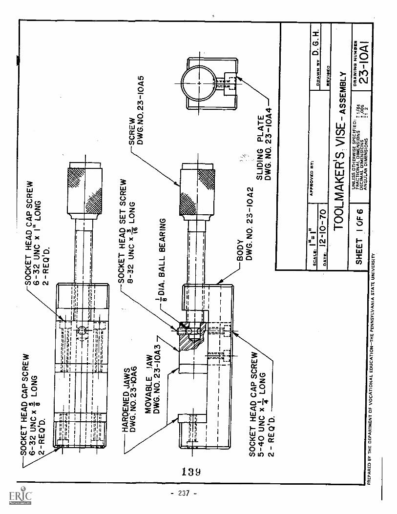
SO
CK
ET
HE
AD
CA
P S
CR
EW
\6-32
UN
C x
?i L
ON
G2-
RE
CIO
D.
SO
CK
ET
HE
AD
CA
P S
CR
EW
6-32
UN
C x
I" L
ON
G2
-RE
Q1D
.".
= =
=...
*--.
-
-"'-1
...1
teII
......
.... .
...c
I
.71T
.__.
...-
--.B
..1
,-..
-...
7.-.
-..
= -LA
HA
RD
EN
ED
JA
WS
DW
G. N
O. 2
3-10
A6
MO
VA
BLE
JA
WD
WG
. NO
. 23-
I043
SO
CK
ET
HE
AD
SE
T S
CR
EW
8-32
UN
C x
-I L
ON
G16
DIA
. BA
LL B
EA
RIN
G
SO
CK
ET
HE
AD
CA
P S
CR
EW
5-40
UN
C x
I- L
ON
G2
- R
EQ
'D.
SC
RE
WD
WG
.NO
. 23-
1045
BO
DY
DW
G. N
O. 2
3-10
A2
SLI
DIN
G P
LAT
ED
WG
. NO
. 23-
I044
AP
PR
OV
ED
BY
:S
CA
LE:
DA
TE
:12
-10-
70D
RA
WN
BY
D. G
. H.
RE
VIS
ED
TO
OLM
AK
ER
'SV
ISE
- AS
SE
MB
LY
SH
EE
T1
OF
6U
NLE
SS
DT
HE
RW
ISE
SP
EC
IFIE
D:
FR
AC
TIO
NA
L D
IME
NS
IDN
SD
EC
IMA
L D
IME
NS
ION
SA
NG
ULA
R D
IME
NS
ION
S
t 1/6
4t .
005
±1
2P
RE
PA
RE
D B
Y T
HE
DE
PA
RT
ME
NT
DF
VO
CA
TIO
NA
LE
DU
CA
TIO
N-T
HE
PE
NN
SY
LVA
NIA
ST
AT
EU
NIV
ER
SIT
Y.
DR
AW
ING
NU
MB
ER
23-1
0A1

JOB SHEET
Job No. J-23-10-57 Drawing No. 23-10A2
TOOLMAKERS VISE - BODY
EQUIPMENT: Vertical milling machine or horizontal milling machine, surfacegrinder, and power cutoff saw.
TOOLS: scriberfile cardlayout dyecutting oil5/16" drill
SAFETY PRECAUTIONS:
11/64" drill6" steel rulelayout hammersurface gauge0-1" micrometer
10" mill file17/64" counterbore3/8"-16 N.C. tap set0-6" vernier caliperdepth micrometer
1. Use brush for cleaning away chips.2. Keep hands and tools away from revolving cutter.3. Check grinding wheel for cracks.4. Keep hands away from revolving grinding wheels.
PROCEDURE:
1. Select required material and cut to rough length on power cutoffsaw.
2. Mount work piece on milling machine.3. Mill ends to length and remove burrs.4. Layout vise cavity.5. Remount work piece on milling machine.6. Mill cavity allowing approximately .010" for grinding.7. Mount work piece on surface grinder.8. Square top, bottom, and sides by surface grinding.9. Clamp to angle plate and grind both ends square.
10. Layout 1/4" and 1/2" grooves and hole locations.11. Remount work piece on milling machine.12. Mill grooves.13. File 1/32" x 45° angle along cavity side of groove.14. Remount work piece on milling machine.15. Surface grind faces for fixed jaws and rails between jaws.16. Clamp work piece to angle plate on milling machine.17. Drill 11/64" holes.
- 239
140

Job No. J-23-10-57Page 2
18. Counterbore 11/64" holes to 17/64" as specified.19. Drill 5/16" hole.20. Tap 3/8"-16 N.C. hole.21. Chamfer 1/16" x 45° all outside edges.22. Remove all burrs.23. Inspect as per print.

-6-4
DR
ILL,
-4-
14 C
'BO
RE
,5 1-
2 D
R,
2 H
OLE
S
3 6
I___
___
-F--
_--7
.--.
'1
...=
.....,
1
-r
"
35 8 2J
- 29 16
6-I-
4 X
450
CH
AM
FE
R
ALL
OU
TS
IDE
ED
GE
S
5,
it D
RIL
L,-I
6 U
NC
- 2
Ba
16
ofg
MA
TE
RIA
L -
AIS
I -10
18 C
.R.S
.
.247
.248
.500
.505
.2 5
0.2
52
SC
ALE
:
DA
TE
:12
-10
-70
AP
PR
OV
ED
BY
tD
RA
WN
BY
D.G
. H.
RE
VIS
ED
TO
OLM
AK
ER
S V
ISE
- BO
D7
SH
EE
T2
OF
6U
NLE
SS
OT
HE
RW
ISE
SP
EC
IFIE
D:
FR
AC
TIO
NA
L D
IME
NS
ION
SD
EC
IMA
L D
IME
NS
ION
SA
NG
ULA
R D
IME
NS
ION
S
± 1
/64
± .0
05±
1 2
PR
EP
AR
ED
BY
TH
E D
EP
AR
TM
EN
T O
F V
OC
AT
ION
AL
ED
UC
AT
ION
-TH
E P
EN
NS
YLV
AN
IA S
TA
TE
UN
IVE
RS
ITY
DR
AW
ING
NU
MB
ER
23-I
0A2

JOB SHEET
Job No. J-23-10-58Drawing No. 23-10A3
TOOLMAKERS VISE - MOVABLE JAW
EQUIPMENT: Vertical millihg machine, surface grinder, and metal cutting bandsaw.
TOOLS: scriberfile cardlayout dye1/4" drill
cutting oil11/64" drill10" mill file
SAFETY PRECAUTIONS:
17/64" drill
surface gaugelayout hammer6" steel rule0-1" micrometer#2 center drill
Block part well on magnetic chuck.2. Remove work from table before checking.
PROCEDURE:
#29 drill (.1405)#38 drill (.1015)5-40 N.C. tap set8-32 N.C. tap set17/64" counterboreadjustable tap wrench
1. Select required material and cut to rough length on band saw.2. Mount work piece on milling machine.3. Mill ends square allowing .005" at each end fur finish.4. Mount work piece on surface grinder.J. Grind block square.6. Layout offset on bottom of jaw.7. Remount work piece on milling machine.8. Mill offset allowing .005" on all surfaces for grinding.9. Layout hole locations.
10. Orill #38 holes.11. Tap 5-40 N.C. holes.12. Drill 17/64" hole.13. Drill 11/64" holes.14. Counterbore 11/64" holes to 17/64" as specified.15. Drill #29 hole through 17164" hole.16. Tap 8-32 N.C. hole.17. Remount work piece on surface grinder.18. Grind 1/4° width to allow .001" clearance with mating part.19. Grind 1/4" length to allow .001" clearance with sliding part.20: Remove all burrs.21. Inspect as per print.
- 243 -
143

NO
.29
(.13
6)D
RIL
L,8-
32 U
NC
- 2
BD
RIL
L, C
'BO
RE
64
32x
D p
.64 2
HO
LES
1
61
7 4D
RIL
L x
3D
P.
.247
_,..1
.um
-7iu
IL.
250
.248
1-6'
.252
ri16
MA
TE
RIA
L -
AIS
I -10
18C
.R.S
.
NO
. 38
(.10
2) D
RIL
L,5-
40 U
NC
- 2
B,
I DP
2 H
OLE
S4
I"
I"S
CA
LE:
DA
TE
:12
-7-7
0A
PP
RO
VE
D B
Y:
DR
AW
N IS
YD
.G. H
.
RE
VIS
ED
TO
OLM
AK
ER
'SV
ISE
-MO
VA
BLE
JA
W
SH
EE
T3
OF
6U
NLE
SS
DT
HE
RW
ISE
SP
EC
IFIE
D:
FR
AC
TIO
NA
L D
IME
NS
IDN
SD
EC
IMA
L D
IME
NS
ION
SA
NG
ULA
R D
IME
NS
ION
S
± 1
/64
± .0
05±
12
PR
EP
AR
ED
BY
TH
E D
EP
AR
TM
EN
T O
F V
OC
AT
ION
AL
ED
UC
AT
ION
-TH
E P
EN
NS
YLV
AN
IA S
TA
TE
UN
IVE
RS
ITY
DR
AW
ING
NU
MB
ER
23-I
0A3

Job No. J-23-10-59
JOB SHEET
TOOLMAKERS VISE - SLIDING PLATE
Drawing No. 23-10A4
EQUIPMENT: Vertical milling machine, surface grinder, and power cutoff saw.
TOOLS: scriberfile cardlayout dye1/4" drillprick punch
SAFETY PRECAUTIONS:
center punch6" steel rulecenter finder'layout hammer0-1" micrometer
#2 center drill1/4" counterbore#28 drill (.1405)10" mill file
1. Wheel guards should always cover at least one-half of the grindingwheel.
2. Always make a visual check of the grinding wheel before startingthe machine.
PROCEDURE:
1. Select required material and cut to rough length on power cutoffsaw.
2. Mount work piece on milling machine.3. Mill ends square and to length.4. Layout hole location.5. Center drill for holes.6. Drill #28 holes.7. Counterbore #28 holes to 1/4" as specified.8. Mount work piece on surface grinder.9. Grind all surfaces.
10. Grind edges sq are to fit 1/2" groove, allowing .001" clearancefor movement.
11. Remove all burrs.12. Inspect as per print.
- 247 -
1 :3

NO
. 28
(.14
05)
DR
ILL,
4D
IA. C
sBO
RE
-12
DP
.2
HO
LES
Om
+ MA
TE
RIA
L A
ISI 1
018
C.R
.S.
9 1616
15 16
1
AP
PR
OV
ED
BY
:D
.G.
SC
ALE
:21
111
1D
RA
WN
BY
H.
DA
TE
:12
5-7
0R
EV
ISE
D
TO
OLM
AK
ER
'SV
ISE
SLI
DIN
G P
LAT
E
SH
EE
T 4
OF
6U
NLE
SS
OT
HE
RW
ISE
SP
EC
IFIE
D:
,F
RA
CT
VIN
AL
DIM
EN
SIO
NS
t 1/6
4D
EC
IMr.
L D
IME
NS
ION
S:t.
005
AN
GU
LAR
DIM
EN
SIO
NS
tt 2
DR
AW
ING
NU
MB
ER
23-
10A
4P
RE
PA
RE
D B
Y T
HE
DE
PA
RT
ME
NT
OF
VO
CA
TIO
NA
LE
DU
CA
TIO
N-T
HE
PE
NN
SY
LVA
NIA
ST
AT
EU
NIV
ER
SIT
Y

Job No. J-23-10-60
JOB SHEET
TOOLMAKERS VISE - SCREW
EQUIPMENT: Lathe and power cutoff saw.
TOOLS: scriberfile cardlayout dyecutting oilscrew-pitch gaugecenter gauge6" steel rule
SAFETY PRECAUTIONS:
knurling tool#2 center drilllathe collet set1/16" radius tool600 threading tool10" mill file
Drawing No. 23-10A5
left hand toolholderright hand facing toolright hand turning toolJacobs drill chuck with
Morse taper to fitlathe tailstock spindle
1. Be sure knurling tool is clamped short.2. Do not clean knurled areas with a rag or brush'while the lathe
spindle is revolving.
PROCEDURE:
1. Select required material and cut to rough length on power cutoffsaw
2. Mount work piece in collet and face one end.3. Knurl section as per print.4. Turn 11/16" diameter.5. Reverse work piece in collet.6. Face and center drill end.7. Extend work piece 3" and support with tailstock center.8. Turn 3/8" thread diameter.9. Turn 1/4" diameter.
10. Chase 3/8"-16 N.C. thread. Use vise body to check fit.11. Layout location-of ball groove on 1/4" diameter by inserting into
hole in jaw and marking the groove through the 8-32 N.C. tappedhole.
12. Form 1/16" groove and shoulder radius.13. Remove center hole by facing.14. File radius on end of screw.15. Remove all burrs.16. Inspect as per print.
-251 -
147

UN
C-7
8
ME
DIU
M K
NU
RL
8
1Plb
Oc MA
TE
RIA
L -
AIS
I-10
18C
.R.S
.
328
LOC
AT
E G
RO
OV
E W
HE
N
/AS
SE
MB
LED
WIT
HM
OV
AB
LE V
ISE
JA
W
216
25
SC
ALE
:
DA
TE
:12
-7-7
0A
PP
RO
VE
D B
Y:
,D
RA
WN
BY
D. G
. H.
RE
VIS
ED
TO
OLM
AK
ER
'SV
tSE
-SC
RE
W
SH
EE
T5
OF
6U
NLE
SS
OT
HE
RW
ISE
SP
EC
IFIP
.3:
FR
AC
TIO
NA
L D
IME
NS
ION
SD
EC
IMA
L D
IME
NS
ION
SA
NG
ULA
R D
IME
NS
ION
S
,A
1/64
I .09
5t 1
2P
RE
PA
RE
D B
Y T
HE
DE
PA
RT
ME
NT
OF
VO
CA
TIO
NA
L E
DU
CA
TIO
N-T
HE
PE
NN
SY
LVA
NIA
ST
AT
E U
NIV
ER
SIT
Y
DR
AW
ING
NU
MB
ER
23 -
10
A 5

JOB SHEET
Job No. J-23-10-61 Drawing No. 23-10A6
TOOLMAKERS VISE - HARDENED JAWS
EQUIPMENT: Vertical milling machine, surface grinder, heat treating furnace,and power cutoff saw.
TOOLS: tongs
scriberfile cardlayout dyeprick punch
SAFETY PRECAUTIONS:
center punch6" steel rulelayout hammerasbestos gloves6-32 N.C. tap
#2 center drill#36 drill (.1065)10" mill fileadjustable tap wrench
1. Always use tongs when loading or unloading a furnace.2. Be careful to use the correct wheel for the material being ground.
PROCEDURE:
1. Select required material and cut two pieces to rough length onthe power cutoff saw.
2. Mount work pieces on milling machine.3. Square ends to length.4. Layout hole locations.5. Drill #36 hole.6. Tap 6-32 N.C. holes.7. Harden and temper jaws.8. Mount work piece on surface grinder.9. Grind all flat surfaces.
10. Inspect as per print.
255 -
149
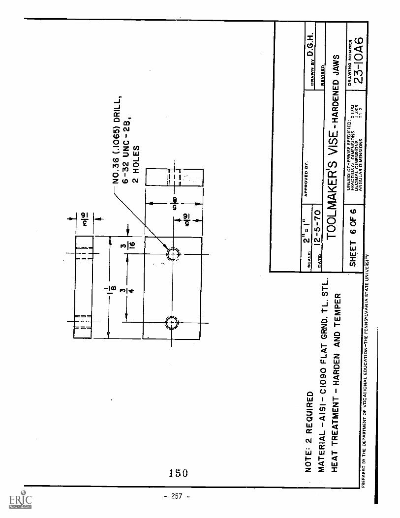
I
inI
IIII
Hll
IIII
0)1
WIi
tii
1
if
I8 3
NO
.36
(.10
65)
DR
ILL,
6 32
UN
C2E
1,2
HO
LES
=
NO
TE
: 2 R
EQ
UIR
ED
MA
TE
RIA
L A
ISI C
I090
FLA
T G
RN
D. T
L. S
TL.
HE
AT
TR
EA
TM
EN
TH
AR
DE
N A
ND
TE
MP
ER
AP
PR
OV
ED
BY
:S
CA
LE:
DA
TE
.12
-5-7
0D
RA
WN
By
D.G
.H.
RE
VIS
ED
TO
OLM
AK
ER
S V
ISE
-HA
RD
EN
ED
JA
WS
SH
EE
T 6
OF
6U
NLE
SS
OT
HE
RW
ISE
SP
EC
IHE
D:
,F
RA
CT
ION
AL
DIM
EN
SIO
NS
= 1
/64
DE
CIM
AL
DIM
EN
SIO
NS
± .0
05A
NG
ULA
R D
IME
NS
ION
St 1
2
DR
AW
ING
NU
MB
ER
23-I
0A6
PR
EP
AR
ED
BY
TH
E D
EP
AR
TM
EN
T O
F V
OC
AT
ION
AL
ED
UC
AT
ION
-TH
E P
EN
NS
YLV
AN
IA S
TA
TE
UN
IVE
RS
ITY

Section 7
OPERATION SHEETS
Operation Sheets su[-lement the job sheets and indicate to thestudent how to perform t 3 operations (skills) necessary to L:ompletethe assigned jobs. The skills (operations) that will be taught inthis course are listed in Section 5B. The operation sheets includedin this section (Section 7) are numbered to correspond with theskill demonstration lessons listed in the COURSE OUTLINE (Section 5).
- 259 -
1 5 1

OPERATION SHEET
Operation Sheet No. SL-1-1
HOW TO: Drill Center Holes
COURSE OF STUDY: Machine Shop Practice - Lathe Operation
INTRODUCTION: Center drilling is the process of drilling and countersinkinga hole with a cone-shaped opening to provide a bearing forthe lathe centers on which work revolves.
TOOLS ANDEQUIPMENT:
PROCEDURE:
Engine lathe, combination drill and countersink.
1. Select a lathe chuck of the size and type suited to thejob.
2. Mount chuck on lathe spindle (refer to Operation SheetNo. SL-1-25).
3. Face end of work square (refer to Operation Sheet No.SL-1-17).
4. Select a combination drill and countersink of suitablesize (refer to Information Sheet No. IL-1-8).
5. Mount drill chuck in tailstock spindle and grip centerdrill in chuck.
6. Slide tailstock forward until the point of the drillnearly touches the work, then clamp tailstock in position.
7. Increase spindle 7peed to accommodate size of drill.shc.Ici always be higher than turning speed.
8. Start th lathe.
9. Turn the tilstock handwheel to feed the center drill tothe ;,;ork.
NOTE: Bring the driii up to the face of the revolvingwork and note whether drill point is in linewith center of work piece. If out of alignment,adjust tailstock to permit the drill to centerproperly and prevent drill breakage.
10. Apply a few drops of cutting oil to the point of the drilland feed slowly to the required depth.
-261 -
152

HOW TO:
COURSE OF STUDY:
INTRODUCTION:
TOOLS ANDEQUIPMENT:
PROCEDURE:
OPERATION SHEET
Operation Sheet No. SL-1-2
Mount Work Between Centers
Machine Shop Practice - Lathe Operation
Work that is to be turned accurately and concentricallybetween lathe centers must be mounted correctly in orderto provide a good bearing and support for the center holesof the job.
Some of the important factors to be considered in themounting of a job between centers are: the alignment oflathe centers, the trueness of the live center, the conditionof the center holes, the lubrication of the tailstock center,the adjustment of the work between centers and the adjust-ment of the lathe dog in regard to the work and driver plate.
Engine lathe, lathe centers, lathe dog and wrench, and leadhammer.
1. Select the lathe dog suited to the job at hand.
2. Attach the lathe dog to the work with the bent tailpointing away from the job and in position to be drivenby the driver plate.
NOTE: Finished surfaces should be protected with apiece of soft brass or copper so that, whentightened, the set screw will not mar the work.
3. Clean the tapered holes in the headstock and tailstockspindles.
CAUTION: Stop the lathe when wiping the spindle hole.The fingers should never be put into a
revolving spindle to remove dirt. A safe andeffective way of wiping the spindle bore isto use a piece of cloth wound around a stick.
4. Examine the lathe centers and spindle sleeve to makesure they are free of burrs. Remove burrs or raisedends with a file or oilstone wipe surfaces clean.
5. Fit the dead center to the hole in the tailstock spindle.

!ration Sheet No. SL-1-2)e 2
6. Insert the live center in the spindle sleeve, mountin headstock spindle, and then tap into positionwith a lead mallet.
7. Rotate the lathe spindle, by power, to check the true-ness of the live center. If center runs out, removeit from the spindle by jarring it loose with a knockoutbar. Recheck for dirt or burrs and reassemble.
8. Check approximate alignment of lathe centers by slidingthe tailstock forward until the two centers are nearlytouching, correct any error in alignment by adjustingset-over screws.
9. Clean the threads of spindle nose and driver plate.
10. Apply a few drops of oil to the threads and mount thedriver plate on the spindle.
11. Clean the ways of the lathe, move the tailstock intoapproximate position to accommodate the length of workand clamp.
12. Clean the center holes of the work. Apply a few drops ofwhite lead and oil mixture to the tailstock center hole.
13. Hold the work in the left hand and place the countersunkhole on the headstock center so that the tail of thedog is freely engaged in a slot on the driver plate. Incase the tail of the dog does not enter the slot freely,loosen the set screw and adjust the dog so that the taildoes not bind against the sides of the slot.
14. Move the center toward the work by turning the tailstockhandwheel. When the job is supported on the centers,adjust the dead center so that no play can be feltbetween the work and the centers. At the same time, thework should be free enough so that the weight of the dogis sufficient to cause it to drop when moved to one sideof the slot.
- 264 -
1 5

HOW TO:
COURSE OF STUDY:
INTRODUCTION:
TOOLS ANDEQUIPMENT:
PROCEDURE:
OPERATION SHEET
Operation Sheet No. SL-1-3
Face Work Mounted Between Centers on a Lathe
Machine Shop Practice - Lathe Operation
Facing or "squaring" on the lathe is the process of machiningends of work flat, smooth, at right angles to the axis of thejob, and to the required length.
Engine lathe, half center, lathe dog, and steel rule.
1. Mount the work between centers, using a half center inthe tailstock.
NOTE: The adjustment of the tailstock center is animportant consideration in facing. When thetailstock center is out of line toward theoperator, a concave end is formed. If thetailstock center is out of line away from theoperator, a convex end will result.
2. Select a facing tool of kind and shape desired andmount it in toolholder with the point of the tool onlevel with the point of the tailstock center.
3. Adjust the compound rest to 300.
4. Set the cutting edge of the tool against the end of thework at an angle slightly more than 900 to permit thepoint to do most of the cutting.
5. Start the lathe.
6. Move the carriage and cross slide to bring the point ofthe tool in contact with the end of the work.
7. Lock the carriage in position by tightening the carriagelock.
8. Back the cross slide out so that the tool clears thework.
9. Feed the tool into the work by turning the crossfeedhandle to rough face end.
- 265
155
Operation Sheet No. SL-1-3Page 2
NOTE: The proper amount of material can be removedby feeding the compound rest in twice theamount to be removed.
10. Finish face end by starting tool at center and facingoutward. A light cut is taken by feeding the tool intothe work a slight amount with the compound rest.
11. Start the cut by hand with the crossfeed handle and thenengage the power feed.
12. Mount the work end for end on the lathe centers andrepeat the facing operation on the opposite end.
- 266 -
156

OPERATION SHEET
Operation Sheet No. SL-1-4
HOW TO: Straight Turn Between Centers
COURSE OF STUDY: Machine Shop Practice - Lathe Operation
INTRODUCTION: Straight or cylindrical turning, on the lathe, is theprocess of machining a revolving piece of work by feedinga cutting tool longitudinally along the piece, in order toproduce sides that are parallel to the axis of the work.
TOOLS ANDEQUIPMENT: Engine lathe, outside calipers, micrometer calipers, and
steel rule.
PROCEDURE: 1. Align lathe centers (refer to Operation Sheet No. SL-1-5).
2. Mount work between centers (refer to Operation Sheet No.SL-1-2).
3. Set the outside calipers to required diameter.
4. Place a right-hand turning tool in the toolholder.
NOTE: Make sure that the tool is ground to propershape, rake and clearance (refer to OperationSheet No. SL-1-26). Adjust the toolholder inthe tool post so that the cutting tool isinclined slightly toward the tailstock to preventdigging into the work when taking heavy cuts.
5. Set the cutting edge of the tool at the height of center.
6. Move the carriage along the ways to make sure that thetool can travel to the desired length without interference.
7. Engage headstock gears or shift belt to obtain correctspeed for material to be turned (refer to OperationSheet No. SL-1-24).
8. Start the lathe and feed the tool in until it touches therevolving work. Move the carriage to the right so thatthe tool clears the end of the work piece.
9. Set the graduated collar at "zero" and then turn thecross slide handle to move the tool in to the desireddepth of cut by taking the reading on the graduated collar(refer to Information Sheet No. IL-1-18).
- 267 -
157

Operation Sheet No. SL-1-4Page 2
NOTE: Lost motion or "backlash" in the cross slideand compound rests can be overcome by turningthe feed screw in toward the work for each cut.
10. Move the carriage, by hand, and take a cut of 1/16"or 1/8" from the end to permit measuring the diameter.
11. Stop the lathe and measure the work, for size, withthe calipers.
CAUTION: Calipers should never be used on revolvingwork. Always stop the lathe when takingmeasurements.
12. Make the necessary adjustments for the depth of cut.
13. Engage the longitudinal feed clutch and start the cut.
CAUTION: Under no circumstances are chips to beremoved by hand. In order to preventpersonal injury, use a hook pliers or apiece of wood to remove chips.
14. Rough turn the job to the desired length.
15. Disengage the feed and stop the lathe.
CAUTION: The frictional heat, which develops as thepiece is being turned, causes the work toexpand and tighten on the lathe centers.If the centers develop a squeak, disengagethe feed, stop-the lathe, loosen the tailcenter, and apply white lead and oil.Readjust the work on centers.
16. Caliper both ends of the job to determine whether thework is parallel.
NOTE: If the work is not turned parallel, makenecessary adjustment on the tailstock to alignthe lathe centers.
17. Insert a keen edge finish turning tool in the toolholder. Set point on center and clamp securely.
18. Decrease the amount of feed and increase the spindlespeed for finish turning (refer to Operation SheetsNo. SL-1-23 and 24).
4
- 268 -
158

Operation Sheet No. SL-1-4Page 3
19. Return the carriage to the starting position (tailstockend of work piece), bring the point of the tool incontact with the revolving work.
20. Reset the graduated collar on the cross slide, to zeroand move the tool in to take a light.cut.
21. Take a trial cut for a short distance and measure thediameter with the micrometer caliper.
22. Make the necessary adjustments, in depth, to get thepiece down to finish size by taking short trial cutson the end of the piece.
23. Finish turn the job to the required diameter.
24. Return all tools to proper place.
25. Clean machine.
159- 269 -

OPERATION SHEET
Operation Sheet No. SL-1-5
HOW TO: Align Lathe Centers
COURSE OF STUDY: Machine Shop Practice - Lathe Operation
INTRODUCTION: The tailstock of the lathe is constructed so as to providea transverse movement of the tailstock body on its base plateat right angles to the ways of the lathe. The body can bemoved in either direction by adjusting screws. The amountof movement may be measured on a scale at the back or frontends of the tailstock.
TOOLS ANDEQUIPMENT:
PROCEDURE:
The lathe centers must be in exact alignment to turn a truecylinder. When the centers are in alignment, the axis ofthe live center coincides with that of the dead center.
The method of checking the accuracy of alignment dependslargely on the nature of the work. The approximate methodof aligning lathe centers is satisfactory for work to berough turned or where great accuracy is not required. Thecenters may be checked for approximate alignment by eitherbringing the live and dead centers together, or by adjustingthe "witness marks" on the tailstock until the "zero" linescoincide.
Engine lathe, open end wrench and/or screw driver.
1. Mount live center in headstock spindle and check fortrueness.
2. Wipe the ways of the lathe clean.
3. Slide the tailstock along the ways until the live anddead center are within a short distance of each other.
4. Clamp tailstock to lathe bed, turn the handwheeljobring the tail center close to the point of the headstock center, and clamp the spindle.
5. Look.down over the centers and note the alignment of thecenter points. If the tail center is out of line, makethe necessary adjustment by turning the set-over oradjusting screws.
160
-271
Operation Sheet No. SL-1-5Page 2
NOTE: In order to move the tailstock body on itsbase plate, it is necessary to loosen theclamping bolt, to permit adjustment by theset-over screws.
Lathe centers may also be checked for approximate align-ment by adjusting the tailstock body on its base untilthe "zero" line of the witness marks coincide.
- 272 -
161

OPERATION SHEET
Operation Sheet No. SL-1-6
HOW TO: Turn Shoulders
COURSE OF STUDY: Machine Shop Practice - Lathe Operation
INTRODUCTION: Shoulder turning is the process of machining the surfacebetween two different diameters to a definite shape. Thereare three general types of shoulders: the square corner,which is usually turned with either the right or left-handfacing tool or a side tool; the filleted corner, which may beturned with a round nose turning tool or radius tool; and thebeveled or angular shoulder, which may be formed with thechamfering tool, the square nose tool, or the side of aturning tool.
TOOLS ANDEQUIPMENT: Hermaphrodite caliper, engine lathe, tool bits for shoulder
turning, toolholder, scriber, steel rule, and chalk or lay-out dye.
PROCEDURE: A. Procedure Common to All Shoulders
1. Lay off the location of the shoulder from the facedend of the work.
2. Set up lathe for turning.
3. Turn the diameter of the work to within 1/64" of thefinished size and allow sufficient material at the shoulderto permit turning to the desired shape.
B. How to Turn Square Shoulders
1. Finish turn the diameter to the required size and leaveenough material at the shoulder for facing.
2. Set up lathe with facing tool.
3. Rough turn the remaining material at corner of shoulder.
NOTE: Where a considerable amount of material is tobe removed, it may be "stepped off."
4. Move the point of the tool in toward the finished diameterso that it barely touches the surface, then set thegraduated collar on the cross slide at "zero."
5. Back the tool away from the work.
- 273 -
1642

Operation Sheet No. SL-1-6Page 2
6. Move the point of the tool against the shoulder of therotating work and take a light cut by feeding inward tothe "zero" setting on the graduated collar. Face theshoulder to split the scribed line.
NOTE: The distance to the shoulders may be laid off byuse of the hermaphrodite caliper or the steel ruleand scriber. The work may be coated with chalk orlayout dye to make the scribed lines more visible.
7. Feed the tool inward again slightly beyond the "zero"setting of the graduated collar. Then move the toolaway from the shoulder so that the diameter at the cornermerges with the finished diameter of the work.
C. How to Turn Filleted Corners
1. Set up lathe with round nose turning tool or filletingtool ground to the required radius.
2. Rough face the shoulder almost to the scribed line (sothat the approximate length is reached). Rough turnexcess material left by the turning tool at corner ofshoulder.
3. Finish turn the diameter of the work to the required sizewith the round nose tool. When proper depth of cut hasbeen reached, set the graduated collar on the cross slideat "zero."
4. Disengage the longitudinal feed before the tool reachesthe shoulder. Move the carriage slowly and carefully byhand until the tool cuts a slight amount off the face ofthe shoulder; then lock the carriage and feed outward.
NOTE: Decreas ,. spindle speed to overcome chatter andto breve 't -me radius tool from digging in at thecorner.
5. Measure length of work to shoulder. Take additional cutson shoulder to face the work to the required length byfirst moving tool to the zero setting on the graduatedcollar and then facing outward.
- 274 -
1d3

Operation Sheet No. SL-1-6Page 3
D. How to Turn Beveled or Angular Shoulders
1. Finish turn diameter of work to required size andleave sufficient material at the corner to form theangular shoulder.
2. Set up lathe with the chamfering tool ground at therequired angle.
NOTE: A square nose tool or a facing tool set at therequired angle may also be used for this purpose.
3. Feed the tool in to remove the excess material at cornerof shoulder.
4. Set the graduated collar on the cross slide at "zero"when the end of the tool barely touches the finisheddiameter of the work.
5. Decrease the spindle speed of the lathe to overcomechatter.
NOTE: The chamfering tool and the square nose tool,when used like forming tools, should be operatedat reduced spindle speed.
6. Move the carriage by hand and cut the shoulder to therequired length.
- 275 -
16,1

OPERATION SHEET
Operation Sheet No. SL-1-7
HOW TO: Round anu Chamfer Turned Edges
COURSE OF STUDY: Machine Shop Practice - Lathe Operation
INTRODUCTION: Chamfering on the lathe is the process of turning a bevel inorder to remove a sharp external edge. Chamfers may beturned with a specially ground chamfering tool, a square nosetool, or with the side of any turning tool. An edge may alsobe chamfered with a file. This method is commonly referredto as "breaking an edge."
Rounding corners is the process of turning a small radius onthe ends of work to remove sharp edges. The rounded edge maybe formed with a specially ground radius tool or it may beshaped by filing.
TOOLS ANDEQUIPMENT: Engine lathe, steel rule, hermaphrodite caliper, mill file,
chamfering tool and radius tool.
PROCEDURE: A. How to Turn a Chamfer
1. Set up the chamfering tool at the required angle in thelathe and adjust the cutting edge of the tool on center.
2. Lay off the width of chamfer on end of work using herma-phrodite calipers.
3. Reduce spindle speed of lathe on wide chamfers in orderto overcome chatter.
4. Move the carriage by hand to bring the side of the toolagainst the revolving work and cut the chamfer to therequired width.
NOTE: To obtain a smoother finish, lock the carriage andfeed the tool into the work by means of the crossslide.
B. How to Round a Corner with a Radius Tool
1. Set up the radius tool in the lathe, and adjust thecutting edge of the tool on center.
2. Reduce spindle speed of lathe, when turning with largeradius tools.
- 277 -

Operation Sheet No. SL-1-7Page 2
3. Move the tool in so that the radius tool is in contactwith the edge of the job.
4. Lock the carriage. Feed the tool into the work by meansof the cross slide or with the compound rest set at anangle.
5. Remove tool marks with file. Polish with abrasive cloth.
CAUTION: Always make sure that the file is providedwith a handle securely fastened to the tangin order to prevent serious personal injury.
C. How to Round a Corner by Filing
1. Increase the spindle speed of the lathe.
2. Grip the file as for bench filing. With long regularstrokes, file the edge of the revolving work torequired shape.
3. Remove file !narks with abrasive cloth.

OPERATION SHEET
Operation Sheet No. SL-1-8
HOW TO: Turn Grooves
COURSE OF STUDY: Machine Shop Practice - Lathe Operation
INTRODUCTION: Grooving is the process of turning a channel or furrowon a cylinder. The shape of the tool and the depth to whichit is fed into the work governs the shape of the groove.
Grooves are frequently cut at the end of threads or againstshoulders in order to provide a channel into which thethreading tool may run.
TOOLS ANDEQUIPMENT:
PROCEDURE:
Where a grinding operation is to follow the turning process,a groove is cut at the shoulder to provide a clearance forthe grinding wheel.
A "V" groove is used on pulleys for the "V" type belt.
Engine lathe, steel rule, hermaphrodite caliper, and1
outside caliper.
1. Lay off location of groove from faced end of the work.
NOTE: Layout dye is used to make the scribed lines morevisible. The required location of the groove maybe laid Jff by means of a hermaphrodite caliper.
2. Set outside caliper to diameter at the bottom of thegroove.
3. Select grooving tool to cut desired shape.
4. Mount tool in lathe, set the cutting edge on center.
5. Reduce spindle speed of the lathe to overcome chatter.
6. Bring the tool within boundaries of the groove, bymoving the carriage.
7. Slowly feed the tool into the work.
NOTE: Use cutting lubricant to produce a smooth surface.
- 279
167

Operation Sheet No. SL-1-8Page 2
8. Stop the lathe.
9. Check the depth of the groove.
CAUTION: Stop the lathe each time the groove is checkedto avoid catching the caliper on the revolvingwork
10. Feed the tool to the required depth.
NOTE: Feed the tool against the sides of the groove ifit is to be widened.
Grooving tools are sometimes ground narrower thanthe required width of the groove in order toprevent chatter.
280
1 6

OPERATION SHEET
Operation Sheet No. SL-1-9
HOW TO: File and Polish on the Lathe
COURSE OF STUDY: Machine Shop Practice - Lathe Operation
INTRODUCTION: Filing is done to fit one part into another, to obtain a
smooth finish, to round off sharp corners, to remove burrs,or to correct a slight error om a taper. A mill file withits single cut teeth is better suited for these operations.
When filing and polishing on the lathe, the spindle isrotated at higher speeds.
Polishing on the lathe is a finishing operation performedwith abrasive cloth to produce a fine finish.
TOOLS ANDEQUIPMENT: Engine lathe, mill file, file card, and abrasive cloth.
PROCEDURE: A. How to File on the Lathe
1. Adjust spindle of lathe to operate at twice the speedused for turning.
2. Lubricate tailstock center.
3. Move the carriage to the extreme right and remove toolpost.
4. Select a mill file.
CAUTION: Never use a file without a handle.
5. Grasp the handle of the file in left hand and guide theopposite end with the thumb and forefinger of the otherhand.
6. Start the lathe.
7. Place the file on the revolving work, holding the fileat a slight angle. Take long slow strokes at rightangles to the work.
NOTE: Release the pressure on the return stroke withoutlifting the file from the work.
-281 -
169

Operation Sheet No. SL-1-9Page 2
8. Continue to move the file slowly over the revolvirgwork. exerting E. uniform pressure for the full lengthof the file.
NO1E: Apply chalk to the face of the file to preventpinning and clogging.
CAUTION: Under no circumstances sh,)1(1 the file be"rapped" on the ways or any part of the lathe.
9. Move the file along the surfaLe of the work for eachstroke so that each cut everlaps approximately one-halfthe width of the file. Continue until the entire surfcehas been filed.
10. Stop the lathe. Check the diameter of work at intervalsalong the filed surface.
NOTE: Clean the file frequently and rechalk to prevent"pinning."
11. File to required size.
B. How to Polish on the Lathe
1. Select the correct grade of abrasive cloth and cut offa 1" wide strip about 6 to 8 inches long.
2. Set the lathe to high speed, or one step faster than forfiling.
NOTE: Be sure to lubricate the dead center well.
There are several methods you can use to hold the abrasive:
a. Place the abrasive cloth over a file and move itacross the work piece as for filing.
b. Wrap the cloth once around the work piece, and holdthe ends. Move the cloth back and forth.
CAUTION: Be careful that you do not come too closeto the revolving chuck or lathe dog.
-282-
170
Operation Sheet No. SL-1-9Page 3
c. Wrap the cloth once around the work piece. Turn thetoolholder backwards in the tool post. Fasten theends of the cloth between the toolholder and thewedge. Now use the power feed to move the cloth backand forth along the work piece.
3. Apply a small quality of oil to the abrasive cloth.
4. Start the lathe. Place the file with the abrasive stripheld against it on the work. Polish the surface bytaking regular strokes as for filing.
NOTE: Small jobs are polished by holding a piece ofabrasive cloth over the job and applying pressurewith the thumb and forefinger.
CAUTION: Use a.short strip of abrasive cloth when it isheld by hand. Hold the abrasive cloth in sucha manner as to prevent it from winding aroundthe work, as this may cause injury to theoperator.
5. Stop the machine and wipe the polished surface free ofoil and abrasive particles. Check the diameter for sizeand straightness.
6. Continue to polish until the desired degree of smoothnessis obtained. Use successively finer grades of abrasivecloth to produce more highly polished surfaces.
NOTE: A surface which appears more brightly polishedcan be obtained by using dry abrasive cloth inthe final stages of polishing. However, a finergrained and somewhat duller appearing surfacecan be produced by using oil in polishing. Oilon abrasive cloth tends to prevent deep scratchesin the surfaces of the work.
171
- 283 -

OPERATION SHEET
Operation Sheet No. SL-1-10
HOW TO: Knurl on the Lathe
COURSE OF STUDY: Machine Shop Practice - Lathe Operation
INTRODUCTION: Knurling is the process of impressing a raised figure upona cylindrical surface by means of a knurling tool. Theknurl is formed by forcing a hardened roll or pair of rollsagainst the sides of a revolving cylinder. The metal isforced outward against the roll as pressure is applied, andshaped to form either the diamond or straight line patterndepending on the type of knurl used.
TOOLS ANDEQUIPMENT:
PROCEDURE:
Engine lathe, steel rule, hermaphrodite caliper, knurlingtool, and file card.
1. Mount work between centers.
NOTE: Long pieces held in a chuck should be supported atthe end by the ;:ai1stock cr,:tnter to withstand thepressure of the knurling tool.
Center holes should be drilled as large as the sizeof the work will permit in order to provide a largeenough bearing sufficient to withstand the addedpressure caused by the knurling operation.
2. Scribe the boundaries of the knurled portion with ahermaphrodite caliper.
3. Set up the knurling tool in the tool post so that theknurls are approximately the same distance above andbelow the center line of work. Make sure that the facesof the knurls are set parallel to the side of the work.
4. Check the movable head of the knurling tool so that itis free to oscillate to accommodate any variation in thetrueness of the revolving work.
5. Regulate the spindle speed of the lathe to revolve atslow speed in order to start impression of knurl.
6. Feed the knurling tool in so that the rolls touch thesurface of the work. Start the lathe and force theknurls into the revolving piece.
172
- 285 -

Operation Sheet No. SL-1-10Page 2
NOTE: As the impression begins to take form advancethe carriage slightly.
7. Stop the lathe and examine the impression to make surethat both knurls are "tracking" properly and that nodouble impression is being formed.
NOTE: If the beginning impression is doubled, move thetool to a new spot on the work and start again.
8. Regulate the speed of the spindle and the feed of thecarriage to obtain a medium speed and feed.
NOTE: The impression should be started with both rolls onthe work piece. The knurl should not ride over theend of the job.
9. Mesh the knurls with the started impression, then forcethe tool into the work. Engage the longitudinal feedand knurl to required length.
NOTE: Using a stiff brush, apply a good grade of cuttingoil to the surface of the work.
CAUTION: Stop the lathe to remove particles of metal fromthe knurl. Under no circumstances should therevolving rolls or work be wiped with waste,cloth, or with the fingers.
10. Reverse the carriage, increase the pressure on the knurlsand knurl to end of piece.
11. Repeat the operation until the full depth of knurl isreached and a clean cut diamond shaped knurl is produced.
NOTE: Once an impression is started, feed the tool theentire length of knurl without stopping. Ringswill be formed in the knurled surface if the feedis stopped while the job revolves. If the workis stopped and the pressure on 'he tool is notrelieved, the piece may be or "thrownout" of trueness.
- 286 -
173

OPERATION SHEET
Operation Sheet No. SL-1-11
HOW TO: Thread on the Lathe
COURSE OF STUDY: Machine Shop Practice - Lathe Operation
INTRODUCTION: Thread cutting on the lathe is a process of producing aridge of uniform section by cutting a continuous groovearound a cylinder as a cutting tool of required shapeadvances along the revolving work.
TOOLS ANDEQUIPMENT:
PROCEDURE:
Engine lathe, center gauge, steel rule, cutting oil, threadgauge, test nut, 10" mill file, and thread stop.
1. Check the diameter of the turned work piece with the draw-ing and determine the number of threads per inch to be cut.
2. Set the quick change gear box of the lathe to cut therequired number of threads per inch.
NOTE: For quick change gear lathes, set the levers atthe positions indicated on the index plate.
3. Turn the compound rest toward the tailstock and clampit at an angle of 300 with the cross slide.
4. Select threading tool and holder suited to the job athand. Check angle of tool with center gauge.
5. Secure tool and holder in lathe tool post and set thepoint of the tool at the height of the lathe center.
6. Set the threading tool "square" with the work by placingthe edge of the center gauge against the turned side ofthe work and adjust the tool until the cutting pointfits the V-shaped notch in the center gauge.
7. Reduce spindle speed of lathe.
NOTE: The speed should be about one-third to one-fourththat for turning. You will probably have to usethe back gears to obtain this slow speed. Thecorrect speed to use is one that permits you tocontrol the movements of the cutting tool at alltimes. Beginners should use slower speeds untilskill and good judgment have be,n developed. Fine-pitch threads can be cut at i fe-iter speed thancoarse threads.
- 287
174

Operation Sheet No. SL-1-11Page 2
Check to make sure that the feeds are disengaged. Feedchange lever should be in neutral position.
9. The thread stop is placed in position.
NOTE: Thread stop may be placed either in front of or inback of the cross slide, depending on its design.
10. Bring point of tool to work piece so that it barely touches.Adjust thread stop against cross slide and tighten.
11. Set the graduated collar on the compound rest feed screwto zero.
12. Then move the tool away from the work and clear the end.
13. Start the lathe.
14. Engage the split nut with the lead screw.
15. As the tool moves along the surface of the job, feed itin gradually until a light trial cut is taken.
NOTE: When using thread chasing dial, the first cut istaken by engaging the split nut when a selectedline on the dial coincides with the index line.
16. Back the tool away from the work and stop the lathe.Check the number of threads per inch with thread pitchgauge.
17. Return tool to a starting position slightly beyond theend of the work.
18. Turn the cross feed handle into thread stop. Feed thecompound rest in .003 to .005 for the first 3 or 4 cuts.
19. Start the lathe, engage the half nuts and take the firstroughing cut for the length of the thred.
NOTE: Apply a small quantity of cutting oil in orderto produce a smoother cutting action.
20. Withdraw the tool at the end of the thread by quicklyturning the cross slide handle and simultaneouslydisengaging the half nuts while work is revolving.
- 288
1'73

o
o
1
Operation Sheet No. SL-1-11Page 3
NOTE: This will require some practice on the part ofthe student. If the tool is withdrawn after thework has stopped rotating, the chip will breakthe point of the tool.
21. Take successive cuts by decreasing the amount the tool isfed in for each. Cut until the full depth of thread isnearly reached.
NOTE: At this point, clean the threads and check forsize.
22. Continue to take light cuts until thread fits matingpart or test nut.
23. Remove burrs with mill file.
- 289 -
o17 '

OPERATION SHEET
Operation Sheet No. SL-1-12
HOW TO: Turn Angles with the Compound Rest
COURSE OF STUDY: Machine Shop Practice - Lathe Operation
INTRODUCTION: The primary purpose of the compound rest is to turn anglesor bevels. However, the compound rest may also be usedfor turning and boring short tapers, on which the length oftaper is limited to the movement of the slide.
TOOLS ANDEQUIPMENT:
PROCEDURE:
Engine lathe, steel rule, protractor, and hermaphroditecaliper.
1. Refer to drawing for angle of turned part and thendetermine setting required for compound rest. (Refer toInformation Sheet No. IL-1-19.)
2. Loosen clamping nuts or screws on compound rest swivelslide. Swing the compound rest until the requiredgraduation on the base coincides with the index line andthen clamp in position.
NOTE: The base of the compound is graduated n degrees sothat it can be set at any angle to the center lineor axis of the work piece.
The angle at which the compound rest is set isdetermined in the following manner:(a) if the angle with the center line of the work
is given, the compound rest is set to that angle;(b) if the included angle is given, the compound
rest is set to one-half the given angle.
3. Lay off the boundary of the angled side by scribing aline around the job with the hermaphrodite caliper.
4. Mount the toolholder in the tool post so that the cuttingtool will be approximately at right angles to the surfaceto be turned.
5. Adjust the point of the cutting tool to make sure thatit is set exactly at the height of the lathe centers.
NOTE: In angular turning, the point of the tool mustalways be set "on center," in order to reproducethe angle at which the compound rest is set.
177-291 -
Operation Sheet No. SL-1-12Page 2
6. Adjust the carriage and cross slide until the pointof the tool just touches the work. Lock the carriageclamping screw to prevent the carriage from movingaway as the cut is taken.
7. Move the cross slide feed screw to bring the tool inposition for the depth of the first cut.
8. Feed the compound by hand to take a trial cut.
9. Check the angle with a protractor and adjust compoundif necessary.
10. Return the tool to the starting position by turning thecompound rest feed screw in the opposite direction.
11. Take a series of cuts until the tool just splits thelayout line for the width of the angle.
NOTE: To prevent scoring or marring of the finishedsurface, the tool should first be backed awayby means of the cross feed screw before returningthe top slide to the original position.
- 292 -
178

OPERATION SHEET
Operation Sheet No. SL-1-13
HOW TO: Turn Tapers Using the Offset Tailstock Method
COURSE OF STUDY: Machine Shop Practice - Lathe Operation
INTRODUCTION: A taper can be defined as a gradual and uniform increase ordecrease in the diameter of the work piece with respect toprogressive length. The conical shape of the taper providesa wedging action that has many practical applications in themachine shop. The fact that it can be assembled and dis-assembled easily and is automatically self-aligning, makesthe taper ideal for driving and holding drills, drill chucks,reamers, end mills , and milling arbors.
Two general methods of tailstock offset measurement will bediscussed differing only in the degree of accuracy required.A common trait of both methods is distance of the tailstockcenter from the longitudinal center line of the lathe.
When adjusting the tailstock for a tapered cut, the operatorshould remember to move the tailstock toward the working sideof the lathe to turn a taper with the small diameter at thetailstock.
Mention should also be made of the fact that taper turningby this method will probably require some trial and errorcuts to achieve any degree of accuracy.
TOOLS ANDEQUIPMENT: Engine lathe, dial indicator, and 6" steel rule.
PROCEDURE: A. Measurement with Scale (accuracy not an imoortant factor)
NOTE: When making the calculation for distance of offset,be sure to deduct from the length of the taper theamount the center enters the work piece.
1. Move the tailstock to the area of the headstock withsufficient space to measure between the centers.witha steel rule.
2. Adjust tailstock necessary distance by using adjustingscrew located on tailstock base.
3. Check adjustment by measuring between witness marks onthe handwheel end of the tailstock.
293 -
179

peration Sheet No. SL-1-13age 2
NOTE: An additional check is to measure the lateraldistance between the centers.
B. Measurement with Dial Irdicator (some degree of accp..acyrequired)
1. Mount a dial indicator in the tool post.
2. Position the indicator so that the dial reads zerowhen in contact with the tailstock spindle.
NOTE: Be certain that end play is taken up in thecross slide screw.
3. Use micrometer dial collar on cross slide to measurthe movement of the amount of offset required.
4. Adjust the tallstock over with the adjusting screwuntil the ind:cator read.;
5. Recheck indicator readin.! - ..Flugging up the adjust-ing screws.
294 -
180

OPERATION SHEET
Operation Sheet No. SL-1-14
HOW TO: Mount Work on a Mandrel
COURSE OF STUDY: Machine Shop Practice - Lathe Operation
INTRODUCTION: A mandrel, when pressed into a finished hole, provides centerson which the outer surfaces of the job may be turned. Mandrelsmay be pressed into position by using either an arbor press orby "driving" the mandrel with a soft-faced hammer.
TOOLS ANDEQUIPMENT:
PROCEDURE:
Arbor press and mandrel.
I Select mandrel suited to the type of job and size ofbored hole.
2. Wipe mandrel clean, rake sure that the surface is free ofburrs or score marks.
NOTE: Roughness or abrasions on the mandrel may beremoved with an oilstone.
3. Apply a thin film of oil on the mandrel body and in tLmachined hole.
NOTE: Oil is used to prevent seizing and scoring as themandrel is pressed into or out of the job.
4. Insert small end of mandrel into bored hole as far as itwill go.
NOTE: The large end of the mandrel has the size stampedon it.
Mount work on mandrel so that pressure and directionof cut will be toward the largc end of mandrel.This will tend to press the work on tighter as itis being machined, and lessen the possibility ofslipping.
S. Raise ram of arbc. :ress to accommodate the length of themandrel and work. Select the size opening in the tableplate that will give the gre§test support to the work.
- 295 -
1 1

Operation Sheet No. SL-l-14Page 2
I.
6. Place work and mandrel in an upright position on thetable plate and center the end of the mandrel under theram.
7 Hold the work in position with the left hand and lowerthe ram until it just to :hes the mandrel. Check to seethat the mandrel is inserted squarely.
8. Adjust the lever to get best position for maximumleverage.
9. Force mandrel into the work by applying pressure onlever.
NOTE: The amount of pressure to apply depends upon thepart, its size, and nature of work. Just enoughpressure should be applied to prevent the workfrom slipping on the mandrel when a cut is takenlater. Too much pressure will tend to distortthe part and enlarge the hole.
- 296 -

HOW TO:
COURSE OF STUDY:
INTRODUCTION:
TOOLS ANDEQUIPMENT:
PROCEDURE:
OPERATION SHEET
Operation Sheet No. SL-1-15
True Work in the Lathe ChLok
Machine Shop Practice - Lathe Operation
Although a large nurbei of operations common to lathe workare performed with the work held between centers, these sameoperations can somimes be performed to better advantagewhen the work is held in a chuck Operations such asdrilling, boring, reaming, internJ threading and counte;.-boring are common to chuck work, as well as the variousexternal turning operations.
Engine lathe, chalk, and four-jaw independent chuck.
Adjust the chuck jaws to the approximate size of the job.Gauge the position of the jaws by the concentric groovesin the face of the chuck.
CAUTION: Always remove the chuck wrench from the chuckafter adjusting.
Remove burrs from end of job and place work piece inchuck.
3. Grip the work in the chuck by tightening a pair of jawswhich are opposite (2-4) each other. Then tighten theother pair (1-3).
NOTE: The work should be chucked just tight enough tohold it in the chuck, as further adjustment willbe necessary.
4. Check to see th.-4i the jaws are located the same distancefrom th ;,. grooves marked on the chuck face when truing around piece.
Turn'the work by hand to determine whether work runsiprozirwcOy true.
tar the ,athe. Run at a slow speed.
7. %,ark "high spc,ts" on the work with a piece of chalk.The chalk is held in the right hand and is graduall)rought towa:^d the slowly revolving work until it comesin L,Atact N101 The chalk mark will indicate th.?..high spot.
183

Operation Sheet No. SL-1-15Page 2'
NOTE: dold the chalk steadily and firmly to overcomethe tendency of mcring.the chalk in and out withthe eccentricity of the job. The chalk may besteadied by resting against a toolholder.
8. .ate high spot and release jaw opposite chalk mark.tighten opposite jaw.
NOTE: If the chalk indicates a high spot on the workbetween two jaws, release the pressure on the twojaws opposite the chalk mark and then tighten thetwo other jaws.
CAUTION: Adjust one set of jaws at a time so that thejob will not fall out of the chuck.
9. Continue to test and adjust until the work runs true.Then tighten each jaw in turn with equal pressure tohold the work securely.
NOTE: In truing, it 14411 be noted that work is sometimes"skewed" in addition to running out eccentrically.That is to say, the work may be concentric nearthe chuck while the end runs out. This may becorrected by tapping the high :ide lightly witha lead mallet.
- 298 -
181

OPERATION SHEET
Operation Sheet No. SL-1-16
HOW TO: Use Draw-In Collets
COURSE OF STUDY: Machine Shop Practice - Lathe Operation
INTRODUCTION: Round finish stock and work of regular shape can beconveniently chucked in the lathe through the use of draw-incollet chucks.
The draw-in collet attachment is assembled in thP spindleof the lathe. The work is held in the collet and tightenedin place by contracting the front opening as the collet isdrawn in against the taper closing sleeve.
TOOLS ANDEQUIPMENT: Engine lathe, lathe collet set, and draw-in collet attachLent.
PROCEDURE: A. How to Assemble Draw-In Collet
1. Clean spindle bore and taper sleeve. Make sure they arefree of burrs.
2. Insert taper sleeve in spindle and sFat securely.
NOTE: Be sure to screw on the spindle nose cap beforeinserting taper sleeve.
3. Lock spindle of lathe by engaging the back gears.
4. c. let cf size suited tothe job.
5. L*.ne or bu,Ts and wipe clean.
order to obtain accurate results, the colletsize shJuld be the same as the work. While workthat is a fPw thousandths over or under thecollet sizzt may be chucked, the accuracy andefficiency :of the collet is impaired-because thesegmented sides will oct bear evenly along thelength of the work.
6. Insert collet in taper sleeve and turn until the keywayengages ue key in the sleeve.
7. Clean threads in end of draw bar, wipe draw bar clean.
299 -
185
Operation Sheet No. SL-1-16Page 2
8. Extend draw bar through left hand end of lathe spindle.
9. Press palm of right hand against face of collet to keepit from being pushed out of taper sleeve.
10. Turn draw bar handwheel clockwise to engage the threadedend of the collet and draw in until end play is nearlytaken up.
B. P.ow to Chuck Work in a Collet
1. Remove burrs from end of work.
2. Apply a slight pressure with the left hand against thehandwheel to extend end of collet beyond tapred seat.
3. Insert work in collet and allow it to extend far enoughto permit machining.
NOTE: Turn work in collet to make sure it is not"skewed."
4. Steady work with right haJd and turn handwheel clockwisewith left hand until collet is seated in taper sleeveand work is firmly chucked.
NOTE: The draW bar should not be tichtened any morethan is necessary to grip the work securelyenough to permit machining.
To release work from collet, simply turn hand-wel and push against end ofhandwheel to spring the collet open again.
4110
HOW TO:
COURSE OF STUDY:
INTRODUCTION:
OPERATION SHEET
Operation Sheet No.
Face Work Held in a Chuck or Collet
Machine Shop Practice - Lathe Operation
Facing is very often done on the work piece while it is heldand revolved in a three or four jaw chuck. Work held inchuck can be more conveniently faced than work held betweencenters.
TOOLS ANDEQUIPMENT: Engine lathe and steel rule
PROCEDURE: 1. Select a chuck of the size and type suited to the job.
2. Mount chuck on lathe spindle (refer to Operation SheetNo. SL-1-25).
3. Mount and true work in chuck (refer,to Operation SheetNo. SL-1-15).
NOTE: Place work in chuck with as little overhang aspossible in order to prevent chatter.
4. Select facing tool suited to the job and fasten in toolholder.
NOTE: Where a considerable amount of material must beremoved and a roughing cut is necessary, a toolbit ground for rough turning may be used. Ifthe tool is to be fed from the center outward, asin the case of a job having a machined hole, aright hand turning tool may be used. For finishfacing, it is more desirable to start at thecenter, use a right hand tool and feed outward.
5. Adjust point of tool exactly on center.
NOTE: When facing with an ordinary turning tool, setthe toolholder approximately at right angles tc,the face of the work.
Adjust spindle speed of lathe.
7. Start the lathe.
8. Move th carriage toward the headstoci, until the pointof the tool just touches the face of the revolving work.
- 301 -
187

operation Sheet No. SL-1-17page 2
9. Move tool in fo rou°
hi
tl)ot dept11' L car.
ack
ri
10. Turn feed 1d rove tool to of Nvtlivingwc domolete c0
pand.
Measurse work to ow much material must ()removed.
ftool irt°d
0(311',3ch succe!sive ,ut bY 1-11Ing
12. Feedcompo
Lind re5t Nd advanc` comourd.
13.
s, 01feeding otward.
vti tool aen 0rTake
finishing 191 ngt cter owe
14. Break all sharp
015. Center,
drill w°11 10° PerSheet No. sL-1-1).
14,
16. Remove work from 0,100\loosened in order\ Otime
print ,er
(rs to 4ersatino-r
which two 0 VINin trUin Ja
9 opP.

OPERATION si.lET
Operation Sheet No. si....1_18
HOW T0: on th Lathe
couRsE OFM OPachine S
DPill e
practice - Lathe OPeration
hole is frquently drilled to Precede other machiningINTRODUCTION:
tPe4tions, such as: boring, reaming, counterboring anddraPpi
hgTh nature of work MaY require a hole to be
*ill,d eithr from a solid or from a Gored hole beforeanY these operations can be Performed.
En9ine lathe, drill, and steel rule.
A.Opep4ti0n5
Prior to Drilling
1.Mount a lathe chuck (re fer to Operat ion Sheet No.SL-1-25).
ToLs ANDQuIPMENT:
PROCEDURE:
B.
2. Tpuing chuck (lathe \refer to Operation SheetNo. SL-1-15).
3. ,racing chuck work (refer to Operation Sheet No.SL-1-17).
4. NUpillirig center holes (refer to Operation Sheet No.
Drillingthe Lathe
twist drill of size suited to the job at hand.
SNeor Only straight shan k drills can be mountedin a drill chuck. Tapermounted jirectly
shank drills are
tai15tock spindle!nto the taper hole of the
2. m-ount drill in tailstock spindle.
3.tai lstock uP until point of drill is close to end
cf work.Slide
NOTE: mak sure that the spindle is bacK far enough inthe tallstock body when starti ng to drill sothat vihen the s pin_le is exte nded for depth of
iL will not become disengaged from tail-5toQk feed screw.
303 -.
189

Operation Sheet No. SL-1-18Page 2
4. Clamp in position.
5. Adjust spindle speedto material and sizeNo. SL-1-24).
of lathe for ing sot cutt ,eed suited
of drill \ref to Operaer tion Sheet
6. Start the lathe.
7. The drill should be advanced int° t slowly,hework piece
by turning the tail stock handwheel until the holhas
reached its full diameter. APPly cuttiug o.cl.
NOTE: Start drill carefollY SO that the Point
boncentr-jolly
of thedrill cuts
If the hole runs out of trueend of the_toolholder agaih,1 the side
"wobbling.'
Of th-drill and hold it there. Trilis will
butt
tool from
8. Back the drill out of the work
otrhiengZer hole.
°co c'onellY 0
17tevent the
chips from flutes. r-,eed to reouirLidepth.
Do not force drill beyond its abilitY tofreely.
cutNOTE:
The depth of -the hole to be
remove
drilled m9 bemeasured by the graduations
'stockorthespindle, bY measuring th movement of
spindle with a steel
Remove drill from tailstOckCAUTION:next oneration
on the tail
in order flrevent o °
injury that may result fromrorushing
rule.
against the point of the drill.
before
-304_

How TO:
COURSEOF STuDy
NTRODcTION:
I
TOOLS 01.Dr
EQUIPMEN,:
PROCEDURE:
OPERATION SHEET
Operation Sheet No. SL-1-19
3ore on the Lathe
Machine Shop Practice - Lathe Operation
Boring is defined as the operation of enlarging and truing ahole with a single-point tool. The largest size boring toolor boring bar that will clear the hole should always be usedto insure rigidity.
Engine lathe, boring bar and holder, and insi(1 caliper.
1. Select largest size boring tc or boring bar that can be,accommodated in the hole.
2. Mount boring tool in tool post, set cutting edge on centel
NOTE: Where boring bar is used extend only far enoughto clear length of hole to be bored.
Also, check to make sure that the heel of tooldoes not rub and that the position of the cuttingedge of the tool remains at the height of lathecenter.
3. Adjust spindle speed of lathe (refer to Operation SheetNo. SL-1-24).
4, Move the carriage forward so that the cutting edge ofthe tool is close to the edge of the hole to be bored.
5. Start the lathe.
5. Take a trial cut for a short distance into the work piece.
NOTE: If trial cut does not remove all the eccentricity,take addWonal trial cuts until the front of thehole ains true.
7. Stop the lathe.
8. Check the size of the hole with inside calipers.
CAUTION: Calipers should never be used to measurerevolving work.
- 305 -
191

Iperation Sheet No. SL-1-19'age 2
9. Engage the longitudinal feed ard take the first roughingcut to the depth of the hole.
NOTE: Due to the tedency of a boring tool to chatterand spring F.1,1ov from the work under heavy cuts,the amount of 4e.ed may have to be decreased.
10. Check size of hole before taking each succeeding cut,then bore to size.
NOTE: !.eck diameter of hole to make sure that it is not"bell mouthed." If the tool tends to spring away,take additional cuts at the same setting of thetool.
If the boring tool chatters, decrease .indlespeed and feed. Also, check gif::; on cross slideand compound rest, adjust to el nate all play.
- 3C5

OPERATION SHEET
Operation Sheet No. SL-1-20
HOW TO: Ream on the Lathe
COURSE OF STUDY: Machine Shop Practice - Lathe Operation
INTRODUCTION: Reaming on the lathe is the process of sizing a hole to agiven diameter with a reamer so that the hole is machinedround, smooth and straight.
TOOLS ANDEQUIPMENT:
PROCEDURE:
Engine lathe, cutting oil, and reamer.
1. Select reamer and cype of holder to suit the job.Check reamer for size.
2. Mount reamer in tailstock in the same manner as fordrilling.
NOTE: Check the alignment of the tailstock when reamingespecial'iy when the reamer is held in a chuck.The end of the reamer should be aligned with themouth of the hole.
3. Reduce spindle speed to approximately one-half the speedused for drilling.
4. Move the reamer up into posltion so that the cuttingend is supported on the edge of the drilled or boredhole.
5. Start the lathe and at the same time turn the tailst.;ckhandwheel to feed the reamer in the hole.
NOTE: Use a cutting lubricant for the material beingreamed.
6. Feed reamer through the work or to the required depth.
7. Stop the lathe and remove the reamer from the work.
8. Check reamed hole with inside calipers or othermeasuring device.
9. Break sharp corner of reamed hole.
- 307 -
193

OPERATION SHEET
Operatton Sheet No. SL-1-21
HOW TO: Tap on the Lathe
COURSE OF STUDY: Machine Shop Practice - Lathe Operation
INTRODUCTION: The best and simplest way to cut internal threads is with a
tap. The work piece should be held securely in a lathe chuck.The hole to be tapped and the tailstock center must alignperfectly with the center line of the lathe.
TOOLS ANDEQUIPMENT: Engine lathe, tap, tap wrench, and cutting oil.
PROCEDURE: 1. Select tap and tap wrench of required size.
NOTE: Hand taps are designed for reversing in orderto clear out the chips.
Machine taps are designed for continuous tapping.
2. Fasten tap in tap holder.
3. Move tailstock up toward work to accommodate length oftap and clamp tailstock in position.
4. Mount tap between work and tailstock cinter.
5. Engage back gears (or any other meV,I)d of locking spindle)to prevent spindle from turning.
6. Turn tap into work and at the same time turn the tail-stock handwheel.
7. Enough pressure should be exerted at the start to makethe tap catch the thread and prevent it from reaming thdmaterial at the front of the drilled hole.
NOTE: Be sure to use thread cutting lubricant.
8. The hole is tapped to required length.
NOTE: A started tap will feed itself into the workwhen turned.
Additional pressure is not necessary to feed thetap. The tailstock _center is used to follow thetap as it advances and to keep it in alignment.
- 309 -
1 9 -4

Operation Sheet No. SL-1-21Page 2
9. If the hole to be tapped is a blind hole, a plug orbottoming tap should be used.
CAUTION: Care should be taken when tapping blind holes.Avoid forcing the tap near the bottom of thehole, causing it to break.
10. Chamfer end of threaded hole to remove any burrs raisedin tapping.
11. Check for fit, with a gauge or mating part.
310
195

OPERATION SHEET
Operation Sheet No. SL-1-22
HOW TO: Cut-Off Stock on the Lathe
COURSE OF STUDY: Machine Shop Practice - Lathe Operation
INTRODUCTION: "Parting" or cutting-off is the process of machining a groovearound a revolving work piece in order to part it from thepiece held in the lathe chuck.
TOOLS ANDEQUIPMENT:
PROCEDURE:
Engine lathe, steel rule, cutting oil, and parting tool.
1. Select a cut-off tool which will meet the requirements ofthe job.
2. Mount the cut-off tool with the cutting edge at theheight of the tailstock center.
3. Square the tool with the work so that the sides willnot rub in the groove.
NOTE: If an inserted type blade is being used, adjustthe blade in the holder so that it extends 1/32"more than half the diameter of the work. Clampthe holder "short."
4. Spindle speed of the lathe must be reduced.
NOTE: Cutting speeds for "parting" are reducedapproximately one-half to two-thirds of thoseused for turning the same type of material.
5. Make sure that all the "play" has been removed from thecompound rest and the cross slide. Adjust gibs, ifnecessary.
6. Move the carriage to the approximate location forcutting off.
7. Measure length of work piece to be cut off by placing theedge of the rule against the work with the end of therule "butted" up against the cutting edge of the tool
8. The carriage should then be adjusted so that the toolis in position for the required length to be cut off.
-311 -
1 9

)eration Sheet No. SL-1-22tge 2
9. Lock the carriage, this prevents it from moving.
CAUTION: Never try to cut off the work piece whenturning between centers.
10. Start the lathe.
11. Slowly feed the parting tool into the work piece.
NOTE: Grip the cross feed handle with both hands, inthis manner you will be able to feed the toolsteadily and uniformly.
Apply plenty of cutting lubricant.
12. Continue to feed the tool into the work piece until itis parted.
NOTE: If the tool hogs in, turn off power and reversethe spindle by hand. Back out the cutting toolwith the cross feed.
Before the cut is completed, use a file to breakall sharp edges.
- 312
1 97

OPERA1ION SHEET
Operation Sheet No. SL-1-23
HOW TO: Change Feeds on the Lathe
COURSE OF STUDY: Machine Shop Practice Lathe Operation
INTRODUCTION: Feed is the distance the tool advances for each revolutionof the work. If a 1/32-inch feed is used in turning, it willrequire 32 revolutions of the work to turn a distance of1 inch.
TOOLS ANDEQUIPMENT: Engine Lathe
PROCEDURE: NOTE: The quick change gear box is arranged between thespindle and the lead screw, It contains gears ofvarious ratios which makes it possible to machinea variety of screw threads. The same gears may beused for the carriage longitudinal (feed) movement.
1. Select the feed in thousandths required.
2. Move the tumbler lever into the hole directly belowthe selected amount of feed.
3. Set shift lcvers into positions as per instructions onthe index plate.
NOTE: The large numbers on the plate indicate thenumber of threads per inch, while the smallerfigures indicate the feed of the carriage, inthousandths of an inch.
CAUTION: Before turning on lathe, be sure all leversare fully engaged. Check by turning the
headstock spindle by hand.

HOW TO:
COURSE OF STUDY:
INTRODUCTION:
TOOLS ANDEQUIPMENT:
PROCEDURE:
OPERATION SHEET
Operation Sheet No. SL-1-24
Change Spindle Speeds on the Lathe
Machine Shop Practice - Lathe Operation
The spindle controls the speed of the work piece. Powerfor driving the spindle is provided by an electric motor.There are four common methods of changing speeds on thelathe. They are (1) Flat Belt Drive, with three or fourstep pulleys; (2) Geared-Head Drive; (3) Variable SpeedDrive; and (4) Hydraiedic Drive.
Engine lathe.
A. Flat Belt Drive
1. Loosen belt with belt tension handle.
CAUTION: Lathe must be stopped before speed changesare made.
2. Open hinged cover that encloses the headstock conepulley.
3. Place flat belt on desired step on step pulley.
4. Tighten belt by moving belt tension lever in the downposition.
CAUTION: Be sure your fingers are not on the headstockpulley belt when you tighten belt; you canpinch your fingers if they get caught betweenthe belt and step pulley.
NOTE: Belts which are allowed to run loose will creepand slip and cause an overall loss in cuttingefficiency of the lathe. Report any loose orslipping belt to your instructor.
5. Close hinged cover.
- 315 -
1 9 9

peration Sheet No. SL-1-24age 2
B. Geared-Head Drive
CAUTION: Spindle must be stopped before gears areshifted to speed desired.
1. Select speed change by shifting change levers todesired position.
NOTE: Geared-head lathes are not all of the same design.You will have to check shifting lever instructionplate on the machine which you are operating.
If gears do not mesh properly, turn the spindle byhand (or use jog button, if your machine has one)until the shifting levers move into proper position.
C. Variable Speed Drive
CAUTION: With this type of system, the motor must berunning while speed changes are made.
1. Turn speed selection handwheel, at the left side of thelathe, for spindle speed desired.
D. Hydraulic Drive
1. Turn speed control dial to R.P.M. wanted.
NOTE: Speed dial may be set to desired R.P.M. whilespindle is running; when spindle is stopped,clutch will automatically shift to R.P.M. set.
2. Start lathe.
- 316 -
200

OPERATION SHEET
Operation Sheet No. SL-1-25
HOW TO: Mount a Lathe Chuck
COURSE OF STUDY: Machine Shop Practice - Lathe Operation
INTRODUCTION: Chucks hold work by means of jaws which may be adjusted toaccommodate work of varying size or shape. Chucks areequipped with adapter plates which fit three types of lathespindles, the threaded nose spindle, long taper key-drivespindle nose and the cam-lock drive.
TOOLS ANDEQUIPMENT: Engine lathe, lathe chuck, and cradle block.
PROCEDURE: 1. Select a chuck of the size and type suited to the job.
2. Clean the hole of the chuck adapter plate.
NOTE: If adapter plate is threaded, use a springthread cleaner. All other adapter plates,wipe inside with clean rag.
3. Wipe spindle nose clean, remove any dirt or chips.
NOTE: Sometimes the spindle bore is plugged with wasteto prevent chips from entering.
4. Use a "cradle block" or board to support the chuck.
5. Move chuck up against spindle nose.
NOTE: If spindle nose is threaded, turn spindle withleft hand to engage the threads. Screw chuck onspindle by hand. Do not force or jam chuck tootightly against the shoulder.
If the spindle has a standard key-drive taper nose,it has a substantial driving key and a large lock-ing collar which screws onto the chuck as it isslid onto the taper.
With a spindle nose of the cam-lock type, the chuckhas projections which fit into 6 holes in the noseplate. Six clamps hold them securely. Each onemust be tightened individually.
- 317 -
201

OPERATION SHEET
Operation Sheet No. SL-1-26
HOW TO: Grind Lathe Cutting Tools
COURSE OF STUDY: Machine Shop Practice - Lathe Operation
INTRODUCTION: The function of a cutting tool is to remove metal. Thetool should do this work easily, at maximum feeds and speeds.The tool should retain its cutting qualities as long aspossible.
TOOLS ANDEQUIPMENT:
PROCEDURE:
The tool geometry, or cutting angles ground on the tool, playsan important part in machining.
Cutting tools will vary in shape to adapt them to various jobs.There are certain underlying principles governing their shapewhich apply generally. When these principles are understood,the grinding of lathe tools becomes comparatively easy.
Safety glasses, pedestal grinder, tool blank, and oilstone.
CAUTION: Make sure tool rest is set about 1/16 inch fromthe wheel, for safety.
NOTE: Check face of grinding wheel to determine whether itneeds truing or dressing.
Care must be taken when grinding a tool bit; do notoverheat; dip it in water frequently.
1. Hold tool bit in right hand and steady it with the lefthand.
2. Press the end of the tool against the revolving grindingwheel, move it back and forth to shape the end clearanceangle (refer to Information Sheet No. IL-1-5)
3. Hold the left side of the tool bit against the face ofthe grinding wheel to form the side clearance angle andthe end cutting edge angle.
NOTE: Always move the tool back and forth across theface of the grinding wheel to get a uniform grindon tool angle.
-319-
202

Operation Sheet No. SL-1-26Page 2
4. Hold the top of the tool flat against the wheel toproduce the side rake angle.
NOTE: Side rake angle is that surface which forms thetop of a tool and has been ground back at anangle sloping from the side cutting edge.
5. Hold the tool bit with the thumb and index finger ofthe left hand.
6. With the right hand, grasp the back end of the tool.
7. Hold the side cutting edge angle of the tool againstthe grinding wheel.
8. Move the back end of the tool in a swinging motion,right to left. The nose of the tool will followthe natural arc or radius.
NOTE: Make sure the radius is the full length ofthe front clearance uf the tool.
9. Check all the cutting angles for proper clearance.
10. Stone the cutting edge of tool on an oilstone.
- 320 -
203

OPERATION SHEET
Operation Sheet No. SL-1-27
HOW TO: Use the Taper Attachment
COURSE OF STUDY: Machine Shop Practice - Lathe Operation
INTRODUCTION: Taper attachments simplify the turning of tapers, boringtapered holes and the cutting of external or internalthreads on tapered surfaces.
Permanently attached to a lathe, it in no way interfereswith straight turning or other operations when not in use.
There are two types of attachments: the plain taper attach-ment and the telescopic taper attachment. This operationsheet will deal only with the latter.
TOOLS ANDEQUIPMENT: Engine lathe with taper attachment, scriber, and layout dye.
PROCEDURE: NOTE: Tapers are shown on most drawings in taper per footin inches or degrees. On most attachments the grad-uations at the end of the swivel bar are divided intoinches per foot on one end and in degrees (includedangle) on the other.
1. Set the swivel bar to the correct amount of taper andtighten.
CAUTION: Some lathe manufacturers have calibrated theswivel bar to be set at the angle with thecenter line, while other calibrations aredesigned to set the swivel bar to the includedangle. Check with your instructor to determinethe type of calibration the manufacturer hasused on the lathe you are operating.
NOTE: Notice that the right end of the bar is moved awayfrom you if the small end of the taper is to be atthe tailstock end of the work piece.
2. Layout the length to be tapered on the work piece.
3. Move the carriage until the attachment is centered alongthe length to be tapered. Be sure the total taper canbe cut in one setting.
-321 -
20 t

lperation Sheet No. SL-1-27'age 2
4. Lock the attachment to th2 bed.
5. Tighten the binding screw or clamp handle over thesliding block.
6. Make sure that the cutting edge of the tool is exactlyon center.
NOTE: If the tool is not on center, the angle of the cutwill not be the same setting as the taper attachment.
7. Move the carriage to the small end of the taper untilthe cutting edge of the tool is about one inch past theend of the work piece.
8. Turn the cross feed until the cutting tool will take alight cut.
NOTE: Remember that all the backlash must be removedfrom the cross feed screw and the taper attachment.If it is not eliminated, part of the cut will bestraight.
9. Run the carriage in the direction of the taper by handuntil the tool starts to cut the material.
10. Make several cuts until the taper is at least an inchlong. With a rule carefully measure a unit of lengthsuch as 1 or 2 inches.
11. Measure the large and small ends at each point with avftrometer or outside calipers (refer to InformationSheet No. IL-1-12 and Information Sheet No. IL-1-15).
12. If necessary, readjust the taper attachment.
13. Finish turn the taper until the desired size is reached.
NOTE: If the taper is to be ground, allow .008 to .015inch for this operation.
- 322 -
205

OPERATION SHEET
Operation Sheet No. SL-1-28
HOW TO: Use the Tool Post Grinder
COURSE OF STUDY: Machine Shop Practice - Lathe Operation
INTRODUCTION: The tool post grinder is another of many attachments thatmakes the lathe extremely versatile allowing both internaland external grinding cuts. If proper precautions are taken,good results can be obtained. Generally, parts to be groundon the lathe are finished machined with an allowance of .010to .015 inch for grinding.
TOOLS ANDEQUIPMENT:
PROCEDURE:
Engine lathe, tool post grinder, diamond wheel dresser, andsafety glasses.
1. Mount tool post grinder in tool post.
2. Select wheel of proper material, size, and style toaccomplish the job.
NOTE: Before beginning any grinding operations it is ofextreme importance to make provisions to keepabrasive dust from moving or sliding parts of thelathe. To do this, cover the ways with a heavycloth. Place a vacuum line or a pan of water oroil beneath the wheel.
3. True and dress the wheel with a diamond dresser.
NOTE: The diamond dresser should be located on orslightly below the center of the wheel.
4. Mount the work piece in the lathe.
5. Adjust the feed and speed of the lathe.
NOTE: As a general rule, the speed should be about 80to 100 R.P.M. and a feed of .005 to .007 inch.However, this depends to a large extent on thecondition of the machine and the work.
6. Turn on power to lathe and grinder after making sure thereis sufficient clearance.
- 323 -
206

lperation Sheet No. SL-1-28)age 2
z7. Adjust grinding wheel until it just touches the work
piece.
NOTE: Take light cuts to avoid excessive pressurebetween the wheel and work pie-P
8. Engage longitudinal feed.
9. Check work frequently with micromete:
10. Redress wheel before taking final cut.
NOTE: Be sure to take special care in cleaning thelathe upon completing the grinding process.
207
- 324 -

OPERATION SHEET
Operation Sheet No. SL-2-1
HOW TO: Cut Off Material
COURSE OF STUDY: Machine Shop Practice - Power Cut-off Operation
INTRODUCTION: Stock is round cut to length with either a Ower hacksaw ora continuous blade horizontal band saw. This Operation SheetNo. SL-2-1 will deal with the continuous blade type only.
TOOLS ANDEQUIPMENT: Continuous blade horizontal band saw and steel rule.
PROCEDURE: NOTE: Refer to Information Sheet No. IL-2-2 for types andkinds of blades for power saws.
1. Make sure vise jaws are at right angles to saw blade.
2. Adjust .the roller guide brackets so they are only slightlywider than the stock to be cut.
3. Place the material in the vise.
4. Lower the blade until it just clears the work.
5. Hold a steel rule against the edge of th blade andmove the material until the correct lens-, , :s obtained.
NOTE: Always cut material 1/8" longer than required.
6. Tighten the vise and recheck length.
7. Start the saw.
8. Grasp the handle of saw frame and lower the blade slowlyto start the cut.
CAUTION: Never drop the blade quickly.Never apply extra hand pressure to the frame.
NOTE: Use coolant if the machine has it.
9. Release hand from handle of saw frame, saw will nowfeed by itself.
10. The machine will automatically shut off when the cut iscompleted.
11. Recheck length of cut off material.
- 325 -
208

OPERATION SHEET
(peration Sheet No. SL-2-2
HOW TO: Saw to a Layout
COURSE OF STUDY: Machine Shop Practice - Band Machining Operation
INTRODUCTION: The vertical band saw is widely used in the metalworkingtrade. It is used for a great variety of sawing and machiningoperations. Industry has profited by its ability to removeexcess material accurately and economically.
TOOLS ANDEQUIPMENT:
PROCEDURE:
Vertical band saw
CAUTION: Wear safety glasses.
NOTE: Refer to Information Sheet No. IL-2-2 for types andkinds of saw blades.
1. Set vertical band saw to the proper speed for the typeof blade and the material being cut.
NOTE: Consult index plate or job selector on machine.
Variable speed band sawing machines must berunning to change speeds.
CAUTION: If your machine has a gear shift control, youmust stop the machine before changing the speeds.
2. Use the workholding jaw or a piece of wood to feed thework into the saw.
CAUTION: Never crowd the blade.
3. Cut to within 1/32 of an inch of the layout lines.
CAUTION: Do not talk to anyone while you are operatingthe saw; if you are not careful you couldloose a finger.
NOTE: When hand feeding, apply uniform pressure,develop a steady hand and a sharp eye to detectpoor cutting performance.
209
- 327 -

OPERATION SHEET
Operation Sheet No. SL-3-1
HOW TO: Meas.re - Linear
COURSE OF STUDY: Machine Shop Practice - Bench Work
INTRODUCTION: Measurement in machine shop practice is an essentialelement in the accuracy of machining. Careful measurementof the work piece insures a correct fit and satisfactoryoperation of the mating parts. A good machinist must beable to measure with speed and accuracy.
TOOLS ANDEQUIPMENT:.
PROCEDURE:
Steel rule
1. To measure a piece of stock, hold the work in yourleft hand and place the rule across the surface to bemeasured.
2. With the rule in your right hand, and using your thumbnail as a guide, extend the rule until the end is evenwith the left edge of the work.
3. Read the graduated markings on the rule &oil left toright and note which line on the rule coincides nearestto the right hand edge of the stock.
NOTE: Select the edge of the rule which is graduatedin fractional divisions of an inch in which thedesired dimension is wanted. The most popularrule is graduated in eighths and sixteenths onone side and thirty-seconds and sixty-fourthson the opposite side.
210
- 329 -

OPERATION SHEET
Operation Sheet No. SL-3-2
HOW TO: Saw with a Hand Hacksaw
COURSE OF STUDY: Machine Shop Practice - Bench Work
INTRODUCTION: The sawing of metal is one of the most common operationsperformed in the machine shop. Because the hacksaw is
used by both skilled and unskilled workmen, it is more orless taken for granted.. It does, however, require propercare and use.
TOOLS ANDEQUIPMENT:
PROCEDURE:
Hand hacksaw, bench vise, and steel rule.
1. Place work in bench vise, the cut should be made about1/4 of an inch from the vise jaw.
2. Select a blade suited to the material being cut (referto Information Sheet No. IL-3-15).
3. Grasp the handle of the saw in the right hand and holdthe frame with the left hand to,guide the saw.
4. When starting the cut, apply the blade to the work toengage as many teeth as possible.
NOTE: Start the cut easily, if you must begin on asharp corner.
5. Apply pressure on the blade on the forward stroke toproduce a cut.
6. Let up on the back stroke.
7. Take long steady forward strokes.
NOTE: Avoid short strokes which will wear a part ofthe blade.
CAUTION: Do not twist the blade in the work, it maybreak the blade.
NOTE: Try to secure a uniform speed of about 40 to 50strokes per minute.
211
-331 -

Operation Sheet No. SL-3-2Page 2
8. Ease up on the forward pressure as the cut gets near theend of the piece.
CAUTION: If the same amount of pressure is maintainedat the end of the cut as is used during thecutting process, the saw blade will suddenlybreak through the material, resulting inserious hand injuries.
NOTE: Refer to Information Sheet No. IL-3-15 for typesand kinds of hand hacksaw blades.
- 332 -
212
OPERATION SHEET
Operation Sheet No. SL-3-3
HOW TO: Square a Work Piece
COURSE OF STUDY: Machine Shop Practice - Bench Work
INTRODUCTION: When layout measurements must be taken from the ends, it issometimes necessary to square up these ends by hand filing.This method of squaring, by hand, is done only when machiningis not necessary.
TOOLS ANDEQUIPMENT:
PROCEDURE:
10" mill file, bench vise, and combination square.
1. Select the proper file (refer to Information Sheet No.IL-3-17).
CAUTION: Do not use a file without a handle.
2. Clamp the work piece to be filed in the bench vise.
3. Grasp the file in one hand, thumb on top, fingers curledaround the handle.
NOTE: Avoid rocking the file, as this will produce anuneven or rounded surface.
4. Push the file and bear down on the forward stroke. Holdthe file parallel to the surface to be filed.
5. Release the pressure and return the file to the originalposition for the next stroKe.
6. Test the work frequently with a combination square todetermine if the surface is straight and flat.
7. Repeat procedure no. 6 until end of work piece is square.
- 333 -
213

OPERATION SHEET
Operation Sheet No. SL-3-4
HOW TO: Use Layout Tools
COURSE OF STUDY: jiachine Shop Practice - Bench Work
INTRODUCTION: Care should be taken in the use of layout tools so thatsharpened and pointed edges are kept in good condition toprevent impairing the accuracy, which is essential to agood layout job. Tools which have pointed ends should beused only for the purpose for which they are intended.
TOOLS ANDEQUIPMENT: Dividers, scriber, protractor, hermaphrodite caliper,
combination square, center punch, and prick punch.
PROCEDURE: A. Scriber
1. Inspect the point of the scriber to make sure that itis sharp.
NOTE: If the point is dull, sharpen it on an oilstoneby rotating the scriber between the thumb andforefinger while moving it back and forth.
2. Wipe the surface of the work piece to be scribed cleanand free of oil, dirt and chips. Apply layout dye.
3. Place the steel rule flat on the work in position forscribing.
4. Grasp the scriber in the right hand as you would a pencil.
5. Hold the rule firmly by exerting pressure with the tipsof the fingers of the left hand.
6. Incline the top of the scriber outward and set the pointof the scriber as close to the edge of the rule as possible.
7. Scribe layout line by exerting pressure on the scriberand drawing it along the edge of the rule.
NOTE: Incline the top of the scriber slightly in thedirection in which it is to be moved.
214
- 335 -

Operation Sheet No. SL-3-4Page 2
B. Combination Square
1. Insert the blade through the slot in the head so that theround clamping groove in the blade engages with the endof the clamping bolt.
2. Extend the blade through the slot to the required lengthand clamp in position by tightening the knurled nut.
3. Place the square head against the work piece and scribelines from the end or either side, according to therequirements of the job.
C. Protractor
1. Insert the blade through the slot in the swivel turret sothat the rounded groove in the blade engages With theclamping bolt.
2. Extend the blade to the required length and tighten.
3. Loosen the clamping screw on the body of the protractorand swing the revolving turret to the desired angle.Tighten the clamping screw.
4. Place the base of the protractor against the side of thework piece and scribe layout lines as required.
D. Hermaphrodite Calipers
1. Be sure the scriber leg point is sharp. Sharpen point onoilstone if dull.
NOTE: Adjust the length of the scriber leg so that it iseven with the inside edge of the rounded caliperleg when it is to be used to scribe lines from theoutside edge of the work piece. When scribinglines with the caliper reversed, set the scriberpoint to the full length of the caliper leg.
2. To set the caliper, loosen the lock nut slightly. Thehooked leg is set on the end of the scale and the legcontaining the scriber point is adjusted to the desiredgraduation on the steel rule. Tighten the lock nut.
3. Grasp the top of the caliper with the thumb and forefingerof the right hand.
- 336-
215

Operation Sheet No. SL-3-4Page 3
. Place the curved tip of the caliper against the surfacefrom which the line is being located.
5. Keep the tip of the caliper leg square with the surfacefrom which it is guided and in contact with the surface.
6. To scribe the line exert a slight pressure on the scriberand draw the caliper along the surface being scribed.
E. Center Punch & Prick Punch
1. Inspect the point of the punch. Make sure the point issharp.
NOTE: The point of a center punch is usually ground toa 900 angle. The prick punch has an angle ofabout 30°.
2. Hold punch in one hand, with the point on the scribedline at the place where it is desired to make indentation.
3. With punch in a vertical position, tap it gently with amachinist's layout hammer.
NOTE: Tap the prick punch lighter than the center punch.The prick punch is used to identify layout linesand for making light indentations for the point ofdividers. Where drilling is to be done, the centerpunch is used to help start the drill. The centerpunch will make a heavier indentation.
F. Dividers
1. Make sure the points of the dividers are sharp.
2. Set the dividers, place one point in the inch mark ofthe steel rule.
3. Turn the knurled adjusting nut with the thumb and forefinger.Adjust the divider until the point of the other leg is onthe dimension you need.
4. To scribe a circle or arc, grasp the top of the dividersbetween the thumb and first finger of one hand.
5. Place the point of one leg on the punched mark.
6. Scribe a circle by swinging the free leg of the dividerin a circular movement.
-337
216

OPERATION SHEET
Operation Sheet No. SL-3-5
HOW TO: Layout
COURSE OF STUDY: Machine Shop Practice - Bench Work
INTRODUCTION: Layout is the transferring of information and dimensionsfrom the drawing to the surfaces of the job. This is doneby scribing or drawing lines to indicate the desired shape,location of holes or openings, angles, or any particularsurface which requires machining, forming or bending.
TOOLS ANDEQUIPMENT:
PROCEDURE:
Surface plate, scriber, combination square, layout dye,steel rule, protractor, file, prick punch and parallel bars.
1. Study blueprint carefully to determine what informationneeds to be transferred to the work piece.
2. Remove oil and grease from work surface and apply layoutdye.
3. Remove all burrs with a file.
NOTE: The ends of the work piece should be made square,by machining or filing.
4. Always work from a given surface or base line, ifpossible.
NOTE: A base line is one from which other requiredlines may be scribed.
5. Place the work on a surface plate so that all dimensionscan be made from a flat surface. If this cannot be done,then the work may be raised by placing parallel barsunderneath.
6. To lay out the location of holes to be drilled, firstscribe the center line along which the holes are to bedrilled. Then scribe a line at right angles to thecenter line at the correct location for the first hole(refer to Operation Sheet No. SL-3-4).
- 339 -
2 17

Operation Sheet No. SL-3-5Page 2
7. Prick punch the intersection.
NOTE: If angular lines must be laid out, it may bedone in one of two ways:(a) Set the correct angle by the use of a
protractor.(b) Mark off the correct dimensions of the angle
from two edges of the work piece, or fromtwo lines at right angles. Then connect thetwo points by using a steel rule or straightedge and scribe along it to get the angle.
8. Parallel lines may also be scribed by using the combinationsquare. Set the blade of the square at the desireddimension and scribe lines at each end of the work piece.Connect these lines with the steel rule or combinationsquare placed on edge.
9. Right angle lines may be drawn by using the combinationsquare or steel square. The blade is held at rightangles to the work and the lines are scribed along theedge of the blade.
10. Check layout with blueprint for errors.
4
- 340 -
218

OPERATION SHEET
HOW TO: File
Operation Sheet No. SL-3-6
COURSE OF STUDY: Machine Shop Practice - Bench Work
INTRODUCTION: A file is a hardened steel cutting tool used by hand tofinish, form, and remove metal. Filing is still an importantpart of machine shop work.
TOOLS ANDEQUIPMENT: Bench vise, 10" mill file, chalk, and steel rule or
combination square.
PROCEDURE: CAUTION: Never use a file without a handle.
A. Straight Filing
1. Place false jaws over steel jaws on bench vise.
2. Clamp work piece in the vise.
3. Select the proper file for the job.
NOTE: Stand with feet slightly apart, with the leftfoot forward. The body weight should bebalanced so that the arms may move easilyforward and backward. You should be able toswing your arms and shoulders freely andcomfortably.
4. Grasp the file handle in the right hand, thumb on top,fingers curled around the handle.
NOTE: For heavy filing, the palm of the left handshould be placed on top end the fingers closedon the underside of the file.
For light filing, hold the tip of the file withthe thumb and first two fingers of the left hand,thumb on top, fingers below.
5. Apply pressure to point at start of stroke.
6. Press with both hands as center of file crosses work.
7. Apply pressure with right hand as end of file crossesthe work.
-341 -
219

Operation Sheet No. SL-3-6Page 2
8. Lift the file slightly on the return stroke.
CAUTION: Do not drag the file back over the work orattempt to cut on the return stroke. Thiswill dull the file.
9. Cover as much distance in one stroke as possible bymoving the file sideways. Work from one end or sideof work to the other.
NOTE: Use a file card to clean the file. Particlesof metal removed by the file frequently lodgein the teeth, these particles or "pins" mayscratch the work if not removed with a file card.
10. Check the filed surface, for flatness, with a steelrule or combination square.
11. Chalk the teeth before final filing.
NOTE: This helps to prevent material from cloggingor being wedged between the teeth.
B. Draw Filing
NOTE: Use a single cut file to produce a better finish.
1. Grasp the file firmly at both ends.
2. Push and pull the file sideways across the work.
3. Hold the file at right angles to the line of stroke.
4. Use the same pressure for both forward and returnstrokes.
NOTE: Clean the file frequently. Chalk the file toprevent pinning.
5. Check the filed surface for flatness with a steel rule ora combination square.
6. Remove the sharp edge which results from draw filing.Hold the file at an angle and make a light stroke acrossthe edge or corners.
NOTE: Draw filing gives a smoother finish on edges andnarrow surfaces than "straight" filing.
- 342 -
220

HOW TO:
COURSE OF STUDY:
INTRODUCTION:
TOOLS ANDEQUIPMENT:
PROCEDURE:
OPERATION SHEET
Operation Sheet No. SL-3-7
Thread with Hand Dies
Machine Shop Practice - Bench Work
Hand dies are used to cut screw threads on external diameterssuch as bolts or rods. It is a tool with an internal threadand is turned or screwed on to the round work piece. As thedie is advanced, the teeth of the die cut the thread.
Die, die stock, and cutting oil.
Clamp work piece securely in a vise.
CAUTION: Use soft jaws on (machined) surfaces to protectthe finish.
2. Select proper die as per print. Fasten the die firmly inthe die holder with the size markings on top. The oppositeside of the die threads are tapered so that it is easierto start the die.
3. Apply a few drops of cutting oil on die threads and placethe die squarely over the end of the rod.
4. Place one hand on the die, apply downward pressure, andturn the die with the other hand until the thread takeshold. Continue for several turns.
NOTE: It is important at this point to check to makesure that the die is cutting square with thework. Correction must be made now or the threadwill be ruined.
5. To correct misalignment of die, back off approximatelyone-half turn then apply extra pressure on the handlewhich was high in relation to the horizontal. Makeanother complete turn on the work to produce a new thread.
6. Check as before, then apply more cutting oil and continueto cut the threads. Turn the die back, approximately one-half turn, frequently to clear away chips.
343 -
221

Operation Sheet No. SL-3-7Page 2
NOTE: The use of cutting oil is important to the finishon threads and the life of the die. Flooding ofthe work is not necessary, as that portion of theoil that runs off is not used, it is only wastedand creates a clean-up problem.
7. After the thread is cut to length, remove the die byturning it counter-clockwise.
8. Check the thread with a gauge or the mating part. Ifthe thread is too large or too tight, close the dieslightly by backing out the set screw in the die slotand tightening the opposing set screws in the die stock.Run the die over the thread again. It may be necessaryto repeat this procedure once or taice to size thethread correctly.
- 344 -
222
OPERATION SHEET
Operation Sheet No. SL-3-8
HOW TO: Use the Micrometer Caliper.
COURSE OF STUDY: Machine Shop Practice - Bench Work
INTRODUCTION: In all machine shop work it is important to develop asensitive touch or feel. This is especially important whenusing precision measuring instruments such as the micrometer.Your sense of touch is very keen in your finger tips. There-fore, when adjusting the micrometer, use only your fingertipsto set the measurement. Before you can acquire the propersense of feel, it is necessary to hold and use a micrometercorrectly.
TOOLS ANDEQUIPMENT: Micrometer and work piece.
PROCEDURE: 1. The micrometer is held in the palm of the right hand bygrasping the frame with the third or little finger,whichever is more convenient. The thumb and forefingerare free to revolve the thimble for the adjustment.
2. Place the work between the anvil and spindle.
3. Turn the thimble down until a light contact is madebetween the anvil and spindle.
NOTE: A sense of "feel" in adjusting the micrometerto the work must be developed. Avoid thetendency to "cramp" the micrometer by usingtoo much pressure.
4. Move the work slightly between anvil and spindle. Thishelps to square and align the piece being measured.
5. Remove the micrometer from the work piece.
NOTE: You may wish to tighten the lock nut beforereading the micrometer, although this is notnecessary unless you wish to preserve thesetting for a purpose.
- 345 -
2 "

Operation Sheet No. SL-3-8Page 2
6. The measurement is taken from the graduations on thebarrel and thimble (refer to Information Sheet No.IL-3-3).
7. Repeat steps 2, 3, 4, and 5 to recheck diameter ofwork piece.
- 346 -
224

OPERATION SHEET
Operation Sheet No. SL-3-9
HOW TO: Chip with a Cold Chisel
COURSE OF STUDY: Machine Shop Practice - Bench Work
INTRODUCTION: Chipping is an operation which requires some degree of skilland cannot be acquired except through proper manipulationof the chisel. There are four kinds of chisels used inmachine shop work. These chisels are made from high gradecarbon tool steel and are produced in many different sizes.
TOOLS ANDEQUIPMENT: Cold chisel and ball peen hammer.
PROCEDURE: 1 Clamp work piece securely in a vise. Use soft jaws toprotect finished surfaces.
2. Select the hammer suited for the job.
NOTE: Hammer weights ranging from 16 oz. to 32 oz. willgenerally take care of most chipping jobs. Holdthe hammer at the end of the handle and grasp itby the thumb, second, and third fingers with thefirst and fourth fingers closed loosely aroundthe handle. The hand does not tire as quickly aswhen the handle is grasped tightly by all fourfingers.
3. Grasp the chisel firmly enough to guide it but not tightenough to absorb the shock of the hammer blows. Thehead of the chisel should be about 1 inch above thethumb and first finger. These two fingers should beslack as the muscles are then relaxed and the fingersand hand are less likely to be injured if struck withthe hammer. The second and third fingers grip thechisel firmly.
4. Hold the chisel on a slant or at an angle that will allowthe cutting edge to follow the desired finished surface.A shallow cut can be made by lowering the head or adeeper cut made by raising the head. After each blow ofthe hammer, the chisel will need to be re-set to theproper position for the next cut.
CAUTION: When chipping always cut away from other workersor keep a wire shield between the job and otherworkers.
225- 347 -

OPERATION SHEET
HOW TO: Polish
Operation Sheet No. SL-3-10
COURSE OF STUDY: Machine Shop Practice - Bench Work
INTRODUCTION: Polishing of metal surfaces is accomplished by wearing orcutting away the metal. The abrasive material used inpolishing is harder than the metal to be polished and isavailable in various grit or grain sizes. Polishing improvesthe appearance of the work.
TOOLS ANDEQUIPMENT: Abrasive cloth, cutting oil, 10" mill file, and file handle.
PROCEDURE: 1. Place work pie:e in vise or holding fixture.
2. Obtain a strip of abrasive cloth of the desired gritsize. This strip should be slightly wider than the widthof the file and long enough to cover the length of thefile face with sufficient excess to allow the strip tobe folded over the tip of the file.
NOTE: The machine finish on the work will determine thegrade of abrasive cloth that should be used first.
3. With the abrasive cloth backed up by the file, place iton the work surface to be polished. Apply a downwardpressure on the cloth and rub back and forth in a straightline across the work surface. Do not rock the file.Keep the file flat on the work surface.
4. Deep scratches or marks can be removed easier if acoarse abrasive is used first. Then follow with mediumgrain size and finish polishing with fine grain cloth.Cutting oil is recommended to be used with each gradeof cloth as it helps the abrasive to cut faster.
5. When all the scratches have been removed, reverse thecloth so that the smooth side will be against the work.Add a few drops of oil and rub the surface for a highpolish.
2 2 (3
- 349 -

OPERATION SHEET
Operation Sheet No. SL-3-11
HOW TO: Tap by Hand
COURSE OF STUDY: Machine Shop Practice Bench Work
INTRODUCTION: Hand taps are used to cut screw threads on internaldiameters. They are made in all standard diameters andpitches. A standard set consists of three taps, each ofwhich has a different starting taper.
TOOLS ANDEQUIPMENT: Tap, tap wrench, and cutting oil.
PROCEDURE: 1. Clamp the work securely in a bench vise making surethat the hole is in a vertical position.
2. Select a tap with the proper taper and clamp it in thetap wrench.
NOTE: The T-handle tap wrench is used for small tapsand the adjustable tap wrench for larger taps.
3. Hold the tap wrench with your right hand cuppeddirectly over the tap and place the end of the tap inthe hole. Position the tap squarely in the hole andapply steady downward pressure while turning thewrench, to the right, two turns.
4. Loosen the wrench and remove it without disturbing thetap. Check to make certain the tap is started straightby using a small square at two points 900 to each other.If tap is not straight, back it out of the hole oneturn, then exert pressure in the opposite direction,and turn the tap back into the hole two or three turns.Check again for squareness.
NOTE: If the tap is not started straight it will cutmore stock from one side than from the other andwill eventually bind and break. Thus the resultwill be a broken tap and a ruined job.
Two or three starts may be required before the tapwill be positioned correctly.
227
- 351 -
Operation Sheet No. SL-3-11Page 2
5. Apply cutting oil to the threads and continue to turn thetap into hole. It is not necessary to continue with down-ward pressure as the tap will pull itself in. It is goodpractice to back off the tap about one-half a turn afterone or two revolutions as this action will break the chips,avoids clogging the flutes and prevents breaking the tap.
6. Continue turning tap forward and backwards until thethread is completed.
NOTE: When tapping a blind hole, it is necessary to usea tap set. Start with a taper tap, follow with aplug tap and finish with the bottom tap.
- 352 -
228
OPERATION SHEET
Operation Sheet No. SL-3-12
HOW TO: Burr an Edge
.COURSE OF STUDY: Machine Shop Practice Bench Work
INTRODUCTION: A burr is the turned-up or projecting edge of metal whichresults from drilling, sawing, and the general processes ofmetal cutting. Careless handling, nicking and dropping arecommon causes of burrs.. Damaged or spoile,1 work is oftencaused by burrs not being removed before clamping the workin a machine, or before measurements are made. Burring isdone to insure accuracy, safety in handling, appearance, andfit.
TOOLS ANDEQUIPMENT:
PROCEDURE:
Bench vise and 10" mill file.
CAUTION: Personal injury may result from burrs and sharpcorners. Be careful when handling!
1. Select the proper file (refer to Information Sheet No.IL-3-17).
CAUTION: Be sure the file has a handle.
2. Clamp the work piece to be filed in the vise.
3. Hold file at a slight angle and push the filealong the edge.
4. Inspect the work frequently.
5. Repeat step 3 until burr has been removed.
NOTE: Be sure the work is free of burrs. Measurementstaken over burrs are often a source of trouble.More accurate measurements can be made on workfree from burrs.
- 353 -
229

OPERATION SHEET
Operation Sheet No. SL-3-13
HOW TO: Use the Pedestal Grinder
COURSE OF STUDY: Machine Shop Practice - Bench Work
INTRODUCTION: This type of grinding is called off-hand grinding becausethe work is held in the hand and controlled by the handsto shape or size it. The operator is protected againstflying abrasive particles and ground material by the wheelguards. Safety glass shields are also provided foradditional protection.
TOOLS ANDEQUIPMENT: Pedestal grinder, wheel dresser, and safety glasses.
PROCEDURE: 1. Make sure tool rest is set on center with grindingwheel; also, it should be no more than 1/16 inch fromthe faLa of the wheel.
2. Adjust safety glass shields, if the grinder has thisfeature.
CAUTION: Wear safety glasses, even though safetyshields may be a part of the grinder.
3. Start the grinder.
CAUTION: Stand to one side of the wheel, for aboutone minute; if a wheel should have a crackin it, it would fly apart by this time.
4. Hold the work in the right hand, and steady it withthe left.
5. Place the work on the tool rest; then guide it againstthe face of the revolving wheel.
6. Apply enough pressure to grind the work piece, dependingupon the hardness of the material.
NOTE: Support the work on the tool rest to steady itwhen grinding. Tool bits can be better guidedby supporting them with the left hand restingon the tool rest.
230
355

peration Sheet No. SL-3-13age 2
OCEDURE:
7. Cool the work in the water pot.
NOTE: Do not overheat hardened tools--they can losetheir temper.
8. Grind the job to the required shape or size by movingthe work back and forth across the face of the grindingwheel. This will prevent wearing a groove in the wheel.
CAUTION: Keep fingers away from revolving wheel. Makesure tool rest is close enough to the wheel toprevent the work from slipping into the spacebetween the two.
NOTE: Do not grind on the side of the_wheel.
9. Check work.
10. Stop grinder.
DRESSING A GRINDING WHEEL
CAUTION: Wear safety glasses.
NOTE: Dressing is the operation of restoring the sharpnessof the grinding wheel by breaking away the dulledabrasive grains, or by removing the loaded or glazedwheel.
NOTE: There are two common types of wheel dressers for off-hand grinders - they are: the abrasive stick and thedisk-type, or star dresser.
1. Procure a mechanical wheel dresser.
2. Start the grinder.
3. Support the dresser on the tool rest so the point ofcontact is slightly above the center.
4. Tilt the handle upward at a slight angle.
5. Gradually apply pressure against the face of therevolving wheel.
356-
231

Operation Sheet No. SL-3-13Page 3
6. Move the dresser back and forth across the face of thegrinding wheel.
NOTE: Hold dresser rigidly enough on the tool restto maintain trueness while dressing..
7. Check the face of the wheel for a straight and sharpsurface.
8. Repeat steps 5 and 6 until wheel surface is clean andstraight.
9. Stop the machine and return the wheel dresser to itsproper place.
- 357 -
232

OPERATION SHEET
Operation Sheet No. SL-4-1
HOW TO: Mill a Flat Surface
COURSE OF STUDY: Machine Shop Practice - Milling Machine Operation
INTRODUCTION: The milling operation determines the setup of the machineand the selection of the cutter. A flat horizontal surfaceis the fi,.st surface to be milled. A plain milling cuttershould be selected. The cutter should be a little wider
than the surface to be milled.
TOOLS ANDEQUIPMENT:
PROCEDURE:
Horizontal milling machine, 10" mill file, and 6" steel rule.
NOTE: See Operation Sheet No. SL-4-10, How to Vouilt theWork in the Milling Machine Vise; and Operation SheetNo. SL-4-9, Mounting the Milling Cutter.
1. Center the work piece directly under the cutter.Tighten the clamp that locks the saddle in position.
2. Adjust the table to bring the cutter to the right-handend of the work.
3. Set the spindle speed selector, on the machine, for the
desired R.P.M.
NOTE: The methods of calculating speeds are coveredin Information Sheet No. IL-4-5.
CAUTION: Always stop the machine before making changesin the revolutions per minute of the spindleor reversing spindle.
4. Set the feed selector for the desired longitudinalfeed.
NOTE: The methods of calculating feeds are covered inInformation Sheet No. IL-4-5.
5. Start the machine. Make certain that the ctter isrevolving in the right direction and the wo-k is clearof the cutter.
233
- 359 -

)eration Sheet No. SL-4-1lige 2
CAUTION: Keep hands and fingers away from revolvingcutter.
Chips should not be removed from the tableby hand.
6. Loosen the clamp that locks the knee.
7. furn the vertical hand crank in a clockwise direction,raising the work piece fairly close to the cutter.
8. Continue more cautiously to bring the work to the cutteruntil it just touches.
CAUTION: Operator should watch the cutter very closelywhile making this final adjustment, avoidcutting into the work.
9. Stop the machine.
10. Turn table traverse wheel to move the work from underthe cutter and t'j permit setting the depth of cut.
11. Set the zero on the graduated dial of the knee to itsindex line.
NOTE: If two sides are to be milled, half the metalshould be removed from each side.
12. Turn the vertical hand crank in a clockwise directionuntil the number on the graduated dial corresponds withthe number of thousandths that are to be removed fromthe work piece in one cut.
CAUTION: Make sure the arbor support and the cutterclear the vise or hold-down bolts.
13. Start the machine, take a trial cut.
14. Feed the table, by hand, into the work for approximately1/4" from the starting end of the work.
15. Stop the machine.
16. Turn the table traverse wheel in a counter-clockwisedirection to back the work far enough away from thecutter to take a measurement of the work.
360 -
231

Operation Sheet No. SL-4-1Page 3
17. If the work piece measures too small, lower the tablethe desired number of thousandths. If the work pieceis too thick, raise the table the desired number ofthousandths.
18. Tighten the clamp that locks the knee in position.Start the machine.
19. Move the work to the cutter so that it just touches.
20. Engage the power table feed.
21. Use cutting fluid for steel (dry if the material iscast iron).
NOTE: Do not stop feeding the work piece while themachine is cutting. If you do, the cutter willundercut at the point where you stopped thefeed.
22. After the cut has been completed, stop the machine.
23. Check the surface.
CAUTION: Never try to feel the finished surfacewhile the cutter is revolving.
NOTE: Never back the work piece under the revolvingcutter. The milled surface will show severalspaced undercuts, one for each revolution ofthe cutter.
24. With a brush, remove all chips from the work piece andsurrounding work area.
25. Remove work piece from vise.
26. Remove burrs and sharp corners raised by the cutter,with a file.
27. Check milled surface for flatness.
235
-361 -

HOW TO:
COURSE OF STUDY:
INTRODUCTION:
TOOLS ANDEQUIPMENT:
PROCEDURE:
A.
B.
OPERATION SHEET
Operation Sheet No. SL-4-2
Square and Indicate a Vise
Machine Shop Practice - Milling Machine Operation
To insure that the work will be machined accurately, the visemust be squared up with the machine spindle.
Milling machine, swivel vise, combination square, and dialindicator.
NOTE: Mount the vise on the milling machine table (refer toOperation Sheet No. SL-4-12). The bottom of the viseand the work table must be wiped clean of cuttings, orthe clamping action will press the dirt into the metaland ruin the finished surfaces.
There are several ways of squaring a vise with thespindle. These will be explained individually.
Squaring a Vise with a Steel Square
1. Place the beam of the square against the face of themachine column.
2. Move the machine table in toward the square so that thesolid jaw of the vise is opposite the blade.
3. Loosen the swivel clamp bolts and adjust the vise so thatthe jaw is parallel with the blade.
4. Tighten the clamp bolts and recheck the alignment.
Squaring a Vise on a Horizontal Milling Machine by Using theMachine Arbor.
1. Raise the machine table so that the arbor is between thetwo jaws.
2. Move the table by hand so that the solid jaw of the viseis against the arbor.
3. Loosen the swivel clamp bolts and adjust the vise so thatthe jaw is parallel with the arbor.
- 363 -
2

Operation Sheet No. SL-4-2Page 2
4. Tighten the clamp bolts and recheck the alignment.
C. Align the Vise with a Dial Indicator
1. Mount the dial indicator on the machine.
NOTE: When using a vertical milling machine, theindicator is inserted into the Jacobs chuck.
When using a horizontal milling machine, theindicator is clamped to either the machinearbor or the mounted cutter.
2 Raise the machine table so that the indicator plungerwill be in line with the face of the solid jaw.
3 Move the table so that the solid jaw bears against theplunger enough to deflect the needle about .015.
4. Move the machine table so that the jaw moves along theindicator plunger. Observe the movement of the indicatorneedle.
5. Loosen the swivel clamp bolts, move the vise accordinglyand recheck the needle movement. Two or three movementsof the vise may be required before alignment is completed.
6. Tighten clamp bolts and make final check.
-364-
23'i

OPERATION SHEET
Operation Sheet No. SL-4-3
HOW TO: Drill on the Milling Machine
COURSE OF STUDY: Machine Shop Practice - Milling Machine Operation
INTRODUCTION: Milling machines - both vertical and horizontal - are usedto produce precision holes in metal parts. Holes are moreaccurately located and aligned through the use of the tablefeed screws. These screws are equipped with micrometercollars. Hole depth is also controlled in the same manner.
TOOLS ANDEQUIPMENT:
PROCEDURE:
Milling machine, Jacobs drill chuck, drill, cente'r drill,and center finder.
1. Secure the work piece in a workholding device.
2. Lower the work table to allow sufficient space for theinsertion of the Jacobs chuck plus room for the drill.
3. Center the spindle over the location of the hole to bedrilled by using a wiggler. Tighten horizontal tableclamps to insure the maintaining of proper alignment.
4. Set the spindle speed and feed desired (refer to OperationSheet No. SL-4-14).
5. Place the drill in the chuck and lower the spindle tomake contact with the work.
6. Start the spindle and feed the drill into the work.
NOTE: If a certain depth is desired, a stop can be setto stop the downward movement of the spindle.
7. When the hole has been drilled to the proper depth,raise the drill and stop the spindle.
8. Remove the drill and return to its proper place.
9. Remove work piece and clean the machine.
CAUTION: Use brush to clean away chips. A cloth willpick up and hold chips. Using the same clothto wipe hands will cause cuts and scratches.
- 365 -
238

OPERATION SHEET
Operation Sheet No. SL-4-4
HOW TO: Calibrate on the Milling Machine
COURSE OF STUDY: Machine Shop Practice - Milling Machine Operation
INTRODUCTION: Calibrating means to divide into equal parts by engraving orcutting lines or graduations on a piece of metal. An examplewould be the graduations on a steel rule.
TOOLS ANDEQUIPMENT:
PROCEDURE:
Milling machine and engraving tool.
1. Clamp work piece into workholding device.
NOTE: Make sure working surface is free of obstructions.
2 Chuck up the engraving or scribing tool and lower thespindle until the tool touches the work.
3. Set the graduated dial on the spindle to zero, then movethe tool off the job and turn the spindle down thedesired depth for the graduated mark.
NOTE: Usually a depth of .005 is sufficient whenusing a 300 pointed tool.
4. Move the point of the tool to the starting place. Setthe graduated dial, of the table screw, to zero.
NOTE: The use of the longitudinal or the transversescrews depends upon the direction the graduationsare to be placed on the work.
5. Move the tool in the desired distance and return it tothe starting pnint. Move the table the requireddistance and repeat the above operation.
NOTE: The length and size of the calibrations aredetermined by the individual requirements.
6. Remove burrs and polish.
239
- 367 -
OPERATION SHEET
Operation Sheet No. SL-4-5
HOW TO: Slot on the Milling Machine
COURSE OF STUDY: Machine Shop Practice milling Machine Operation
INTRODUCTION: Metal slitting cutters are called slitting saws. Slottingincludes a variety of cuts in which various narrow slots arecut part way through the metal. Cut off operations are alsoperformed with this type of cutter.
TOOLS ANDEQUIPMENT:
PROCEDURE:
Horizontal milling machine, slitting saw, and workholdingdevice.
1. Mount workholding device on milling table.
2. Clamp the work piece in the vise.
3. Select the cutter for the width slot required.
4. Mount the cutter on the arbor.
5. Set the feed and speed.
6. Raise the table until the work piece is fairly close tothe cutter. Move the saddle in or out until the cutteris directly over the slot location.
7. Start the machine. Hold a thin, narrow strip of paperbetween the cutter and the work piece to act as a feeler.Raise the table until the cutter tears the paper.
CAUTION: Keep the fingers away from the cutter byusing a long piece of paper.
8. Set the micrometer collar at zero.
9. Move the table to the left of the cutter. Raise thetable the correct depth of the slot or groove plus thethickness of the paper. Lock the knee.
10. Turn on the power, feed the cutter into the work andmachine the slot.
11. Lower the table to clear the cutter, stop the machineand check the dimensions.
240
- 369 -

OPERATION SHEET
Operation Sheet No. SL-4-6
HOW TO: Counterbore on the Milling Machine
COURSE OF STUDY: Machine Shop Practice - Milling Machine Operation
INTRODUCTION: The operation of boring a hole larger in diameter, for partof its length, and concentric with the existing hole, isknown as counterboring. The counterbore must be deep enoughso that the screw or bolt head does not extend above thesurface.
TOOLS ANDEQUIPMENT: Vertical milling machine and counterbore.
PROCEDURE: 1. Mount the work piece in the workholding device.
2. Secure correct counterboring tool and mount in thetoolholder.
NOTE: For straight shanked tools, use a drill chuck;for tapered shank tools, use a sleeve or socketwhere required.
3. Start spindle and check for run out.
4. Set spindle speed at about one-half speed used fordrilling.
5. Adjust spindle stop for required depth.
6. Lower counterbore to the hole, apply cutting oil.
7. Start machine and feed the counterbore slowly by handinto the work.
NJTE: If the counterbore begins to chatter at thestart, stop the mach4ne-and reduce the speed.
8. Raise the counterbore, stop the machine, and then checkthe hole for depth. Make any necessary adjustments tothe spindle stop.
CAUTION: Always stop the machine and allow enoughworking space to prevent injuries to the hands.
-371 -
241

Operation Sheet No. SL-4-6Page 2
9. Return counterbore to hole and feed to required depth.
NOTE: Use additional cutting fluid as needed.
10. Check final depth.
11. Return tool to storage area. Clean machine.
372
242

OPERATION SHEET
Operation Sheet No. SL-4-7
HOW TO: Ream on the Milling Machine (Vertical)
COURSE OF STUDY: Machine Shop Practice - Milling Machine Operation
INTRODUCTION: The purpose of reaming is to finish a previously drilledhole to exact size. Since drilled holes are not finishedto close tolerance or fine surface finishes, it is essentialthat secondary operations follow drilling to meet thesespecifications.
TOOLS ANDEQUIPMENT: Milling machine, safety glasses, vise or T-slot bolts and
parallels and reamer.
PROCEDURE: NOTE: Hole to be reamed has previously been drilled (referto Operation Sheet No. SL-4-3 and Operation SheetNo. SL-6-2).
1. Choose the correct reamer for the job and mount incutter holding device in spindle.
NOTE: If the vertical mill has a tapered shank spindle,a taper shank reamer may be inserted into thespindle. Use a drill chuck or adapter forstraight shank reamers.
2. Reduce spindle speed one-half that used in drilling thehole.
3. Set the correct feed for reaming.
NOTE: In reaming holes of 1/8 inch to 2 inch diameter inlow-carbon steel, it would be well to start witha speed of 60 S.F.M. and a feed to 0.004 to 0.025I.P.R. Speed or feed, or both, can then beincreased until the first signs of tool chatterappear. At this point it is advisable to keepspeeds and feeds below this point for best finishand tool life.
4. Start the machine.
5. With the vertical feed hand wheel or handle, lower thereamer slowly into the hole.
- 373 -
243

Operation Sheet No. SL-4-7Page 2
NOTE: Aligning the drilled hole with the reamerhas alredy been done. The hole was drilled inthe first operation and the table was not moved,henc the hole is still-in alignment with thecerlter of the spindle.
6. Contwe to feed the reamer .!rito the hole, by hand ormacAne feed. Apply cutting oil to the reamer.
NOIE: Sometimes the reamer chatters. Chattering iscaused by vibrations that are set up between thework and the reamer. It may be caused by a dullreamer, or the work piece or reamer may not beheld rigidly enough. Check to see if any ofthese causes need correction. If not, tryreducing the speed.
7. Now proceed with reaming the hole all the way throughwork piece.
8. Return spindle to starting position.
CAUTION: The reamer should never be reversed as it isbeing removed from the hole, as this tends tobreak or dull the cutting edges.
9. Stop machine.
10. Remove the reamer from cutter holding device.
11. Remove piece from workholding device.
12. Return all tools and equipment to proper place.
13. Clean the machine.
374
241

OPERATION SHEET
Operation Sheet No. SL-4-8
HOW TO: Seat a Work Piece in a Vise
COURSE OF STUDY: Machine Shop Practice - Milling Machine Operation
INTRODUCTION: Any part that is to be machined on a milling machine mustbe held securely in a workholding device. The mostfrequently and certainly the most versatile workholdingdevice used is the vise. It will hold many sizes ofstandard shapes, and the work can be secured or releasedquickly.
TOOLS ANDEQUIPMENT:
PROCEDURE:
Milling machine and vise.
1. Clean the vise jaws and the vise opening of all dirt andchips.
NOTE: Clean surfaces are necessary for accuratemachine work.
Compare the depth of the vise jaws with the height ofthe work to determine the necessity of using parallels.The work should extend above the vise jaws slightlymore than is required for machining.
3. Place two narrow parallels between the vise jaws ifrequired.
NOTE: Two parallels are recommended because of the easeof measuring and ease of determining whether thework is properly seated.
4. Burr the entire piece and place on parallels or on thebottom of the vise. Place stips of paper under the fourcorners of the work piece.
5. Center the work in the vise and tighten the vise jaws.Apply enough pressure on the vise crank to hold the piecesecurely during the machining operation.
NOTE: Exerting pressure on the vise jaws produces alifting action. The movable jaw requires a smallamount of clearance in order to function properlyand the pressure causes it to lift, raising thework at the same time.
- 375 -
245

Operation Sheet No. SL-4-8Page 2
6 Tap the work lightly with a lead hammer or mallet tosettle the work on both parallels until the paperfeelers are tight. Use a hammer of leather or plasticon soft materials to avoid damage to the work.
NOTE: The work will bounce or rebound from the parallelsif struck too hard. Any movement of parallels isan indication that the work is not solidly seated.If the parallels are still loose, a heavier blowon the piece will force it down on the parallels.
Further tightening of the vise, after seating,often tends to lift the work, and requiresreseating it.
7. Return tools to proper place and prepare for machiningoperation.
- 376 -
246

OPERATION SHEET
Operation Sheet No. SL-4-9
HOW TO: Mount Milling Cutters
COURSE OF STUDY. Machine Shop Practice - Milling Machine Operation
INTRODUCTION: In general, milling cutters can be categorized into threegroups which depend on the method of holding and driving.The selection of the proper cutter depends on the character-istics of the operation to be performed and the way in whichthe job is set up. In the discussion to follow we will beconcerned with mounting each of the following varieties ofcutters: arbor-type cutters, shank-type cutters, and facing-type cutters. Shank-type cutters (end mills) have straightor tapered shanks. Caution should be used in fitting taperedshank cutters to adapters because of the variety of tapersused.
TOOLS ANDEQUIPMENT: Milling machine, wrenches, soft hammer, end mill, face mill-
ing cutter, plain milling cutter, and Allen wrenches.
PROCEDURE: A. Arbor-Type Milling Cutter.
1. Select the smallest diameter cutter of the proper stylethat will perform most satisfactorily.
NOTE: In some cases this selection is not limited to asingle type of cutter. The smallest diameter,however, will complete the job in less time.
2. Cover table surface with a cloth or board to protect it.
3. Select and mount an arbor that will accommodate the cutterselected.
4. Mount arbor as discussed in Operation Sheet No. SL-4-13.
5. Remove arbor nut.
6. Remove enough spacers to position cutter.
NOTE: The cutter should be located as close to thecolumn as possible.
7. Insert key in arbor keyway.
8. Mount cutter on arbor.
- 377 -
247

Operation Sheet No. SL-4-9Page 2
CAUTION: Cutter should slide freely on arbor; neverforce it on. Make sure cutter teeth willrevolve in the proper direction. Protectyour hands when handling cutters.
9 Place a 2" wide spacer next to the cutter followed bya bearing sleeve for the arbor support.
CAUTION: Be sure all spacers are free from dirt andchips.
10. Add sufficient spacers to the arbor so they extendabout 1/8" over the inner end of the thread.
11. Screw arbor nut on by hand.
NOTE: Do not use wrench to tighten nut at this time;there would be a possibility of springing thearbor.
12. Loosen the overarm clamp and position the overarm sothe arbor support can be mounted.
13. Lock the overarm in position.
14. Place arbor support on the overarm and locate the bearingsleeve centrally in the arbor support bearing.
15. Clamp tr. aroor support to the overarm.
CAUT:ON: Make sure there is enough clearance betweenth =.? arbor s..ipport and the vise'or setup.
16. Tighter arbor nut with a wrench.
CAUTION: Normal wrench pressure is sufficient, do notharhil)er on wrench.
17. Apply coat of oil to bearing surfaces.
NOTE: Some arbor supports are equipped with oilreservoirs and they should be kept full.
18. Remove all equipment used in setup and return them totheir proper places.
- 378-
248

Operation Sheet No. SL-4-9Page 3
B. Shank-Type Cutter (Brown and Sharpe Cam Lock)
1. Select and mount the Brown and Sharpe Cam Lock arbor inthe spindle as described in Operation Sheet No. SL-4-13.
2. Clean the tapered hole in the arbor.
3. Select the proper cam lock end mill.
4. Clean taper and cam throat on end mill.
5. Insert tapered portion of end mill into arbor.
NOTE: Be sure cam throat is in position to receivethe cam.
6. Using an Allen wrench, turn the cam lock clockwise toposition and tighten the end mill.
CAUTION: Remove Allen wrench from spindle.
7. Check the trueness of spindle rotation by starting themachine.
C. Facins-Type Cutters
1. Cover table surface with a cloth or board to protect it.
2. Clean spindle surfaces that contact cutter.
3. Clean cutter contact surfaces.
CAUTION: Use a rag to protect hands while handlingcutters.
4. Position cutter over spindle making sure driving lugs arelocated in the slots of the cutter.
5. Attach the cutter to the spindle using four fillisterhead screws.
6. Tighten screws with Allen wrench.
7. Start machine to see if the cutter is running true.
- 379 -
249
OPERATION SHEET
Operation Sheet No. SL-4-10
HOW TO: Mount the Vise on the Milling Machihe
COURSE OF STUDY: Machine Shop Practice - Milling Machine Operation
INTRODUCTION: The vise is probably the most widely used workholding methodused for milling operations. It is made in the plain stylewhich can be fastened to the machine table with the jawseither parallel or at right angles to the T-slots. It isalso made with a swivel base which allows the vise body toturn in a complete circle. The jaws are hardened to resistwear, and are ground for accuracy.
TOOLS ANDEQUIPMENT:
PROCEDURE:
Milling machine and vise
1 Clean surface of milling machine table free of all oiland dirt, and clean out the table slots.
NOTE: A flat piece of steel, which is made to fitloosely in the slots, is used to keep the slotsclean in order that clamping bolt heads can slipeasily through the slots.
2. Turn the vise on its edge and wipe the machined surfaceclean. Remove any burrs that are found.
3. Insert tongues or keys into the vise slots, which willposition the vise according to the jaw position require-ment.
4. Place the vise carefully on the table, with the tonguesfitted into the correct table slot.
CAUTION: Request additional help when lifting thevise on to the milling table.
5. Place a square T-head bolt in the table slot on eachside of the vise. Slide along the slot and into thevise slots.
250
- 381 -

Operation Sheet No. SL-4-10Page 2
6. Place a washer and nut on each bolt and tighten with a
wrench so that the vise is clamped to the table.
CAUTION: Use a wrench that fits the nut.
NOTE: Be sure a washer is placed over the bolt beforea nut is used. This will prevent the nut frommarring the vise slot.
251
- 382

OPERATION SHEET
Operation Sheet No. SL-4-11
HOW TO: Dismount the Vise on the Milling Machine Table
COURSE OF STUDY: Machine Shop Practice - Milling Machine Operation
INTRODUCTION: A vise, plain or swivel, is the most used workholding devicefor a milling machine, but there are times when othermethods are used. This requires the removal of the vise inorder to make space for another type of fixture.
TOOLS ANDEQUIPMENT:
PROCEDURE:
Milling machine and vise.
1. Clean the chips from the vise and table.
CAUTION: Never use your hands or a cloth to brushaway chips. Use a brush and pan to collectthem.
2. Loosen the nuts on the T-bolts and remove the boltsfrom the T-slots. Place them in their storage rack.
CAUTION: Never use an adjustable wrench on the nuts.
3. Remove the vise from the table and place it ir itsstorage area.
CAUTION: Never attempt to remove a vise from a mill-ing machine table without help. Permanentinjury can result.
NOTE: The storage area should have a wooden base toprotect thP machined area of the vise fromdamage.
4. Use the slot cledner to remove the cuttiNgs to theends of the table. Finish cleaning the machine with abrush and pan.
5. Return all tools to their proper places.
252- 383-

OPERATION SHEET
Operation Sheet No. SL-4-12
HOW TO: Dismount Milling Cutters
COURSE OF STUDY: Machine Shop Practice - Milling Machine Operation
INTRODUCTION: When a job is completed in the machine shop it is customaryto break down the setup and restore the work station to itsoriginal condition. One of the aspects of this clean upis to remove the milling cutter. Even though the cutter hasbeen used to machine a job, it is still sharp enough tocause injury and should be handled with due consideration.It should be a common practice to check the condition of thecutter to determine whether it needs to be sharpened or not.If it does not require sharpening it should be stored in a
location that will insure damage prevention. If the cutteris dull take the necessary steps to get it ground.
TOOLS ANDEQUIPMENT: Milling machine, Allen wrenches, and wrenches.
PROCEDURE: A. Arbor-Type Milling Cutter
1. Loosen arbor nut.
2. Unclamp arbor support from overarm.
3. Remove arbor support from overarm.
4. Unlock overarm.
5. Move overarm back until its front is flush with thecolumn.
6. Remove arbor nut.
7. Remove spacers and bearing sleeve.
8. Remove cutter.
NOTE: Handle the cutter with a cloth.
9. Replace spacers, bearing sleeve, and arbor nut.
10. Remove arbor as discussed in Operation Sheet No. SL-4-13.
253
-385 -

Operation Sheet No. SL-4-12Page 2
B. Shank-Type Cutter
1. Unlock cam using Allen wrench.
2. Remove cutter.
CAUTION: Handle the cutter with a cloth.
3. Remove arbor as discussed in Operation Sheet No.SL-4-12.
C. Facing-Type Cutter
1. Loosen four fillister head screws with Allen wrench.
2. Remove cutter.
CAUTION: Handle the cutter with a cloth.
3. Remove arbor as discussed in Operation Sheet No. SL-4-13.
251
- 386-

OPERATION SHEET
Operation Sheet No. SL-4-13
HOW TO: Mount and Dismount Milling Machine Arbor
COURSE OF STUDY: Machine Shop Practice - Milling Machine Operation
INTRODUCTION: The arbor is the most commonly used cutter holding deviceused on the milling machine. It is made in several sizes,lengths and styles.
The friction or holding power of the taper provides thedriving power for the arbor. The arbor is fitted withdriving lugs for positive drive, and a threaded hole isprovided to receive a draw-in bar to seat the taperedportion solidly in the tapered machine spindle.
TOOLS ANDEQUIPMENT: Milling machine, arbor, draw-in bar, and wrench.
PROCEDURE: A. Mounting the Arbor
1. Protect machine table with cloth or wooden tray.
2. Clean the tapered end of the spindle thoroughly andcheck the spindle hole for dirt and chips.
3. Clean the threads on the end of the draw-in bar to keepchips from dropping into the tapered portion of thespindle, and also to prevent the threads from bindingwhen inserted into the arbor hole.
4. Select the type of arbor required.
5. Clean and examine all over for nicks and burrs.
NOTE: All burrs must be filed, or stoned, if thesurface is hardened. A high spot or dirt willthrow the arbor out of line and cause thecutter to "run out."
6. Insert the draw-in bar into the hole of the spindle fromthe back end of the machine.
7. Insert the arbor into the tapered end of the machinespindle.
NOTE: Make certain that the arbor is seated properlyand that the driving lugs on the face of thespindle are aligned with the slots on the collarof the spindle.
- 387 -
255

Operation Sheet No. SL-4-13Page 2
8. Stand at side of machine. Hold arbor with one handand thread draw-in bar into arbor, with the otherhand, until tight.
NOTE: Damage can result if arbor is pushed fromspindle and falls onto other tools or theunprotected machine table.
9. Lock the spindle by using the spindle lock or shiftinginto back gear.
10. Use wrench to tighten the nut on the draw-in bar.
NOTE: Drawing the nut tight will draw the arborsecurely into place.
11. Release the spindle and start the machine. The arborshould run perfectly true unless it is bent or thereare some particles of dirt wedged between the arborand spindle tapers.
B. Dismounting the Arbor
1. Lock the spindle. With the correct size wrench,loosen the locking nut on the draw-in bar.
2. Back the nut away a partial turn in a counter-clockwisedirection.
3. Tap the end of the draw-in bar lightly with a softhammer (refer to Information Sheet No. IL-3-8).
NOTE: The standard milling machine spindle is designedwith a steep taper so that the arbor will notstick in the spindle and can be easily and quicklyreleased.
4. Unscrew the draw-in bar completely with one hand whilesupporting the arbor with the other.
5. Remove the arbor from the spindle and return to storageplace.
6. Release spindle lock.
256
388 -
OPERATION SHEET
Operation Sheet No. SL-4-14
HOW TO: Adjust Feeds and Speeds on the Milling Machine
COURSE OF STUDY: Machine Shop Practice - Milling Machine Operation
INTRODUCTION: The rates of feed and speed are governed to a large extentby such characteristics as material being cut, type of toolbeing used, ridigity of setup, type and condition of machine,and type of finish desired. Although most modern millingmachines utilize a quick change gear box where the operatordials the speed and feed he wants, there are other methodsused to control these variables. Two common methods are:shifting V-belts and adjusting variable speed pulleys. Thisoperation sheet will be primarily concerned with the moderndialing process.
TOOLS ANDEQUIPMENT: Milling machine
PROCEDURE: 1. Calculate or determine from tables the amount of feedand speed required.
NOTE: If the speed or feed required falls between twosteps on the dial, set the speed or feed at thelower value.
2. By using the shift lever, dial to the speed or feedrequired.
CAUTION: Make all speed and feed changes when thespindle is stopped.
NOTE: It is important for the operator to realize thatmechanisms for selecting speeds and feeds variesfrom machine to machine depending on the manufact-urer. With this thought in mind, if any doubtexists in setting either speed or feed, consultthe manufacturers instructions.
- 389 -
2 5 7
OPERATION SHEET
Operation Sheet No. SL-4-15
HOW TO: Bore a Hole on the Milling Machine
COURSE OF STUDY: Machine Shop Practice - Milling Machine Operation
INTRODUCTION: It is often necessary to enlarge a previously drilled orcored hole on the milling machine and this is generallyaccomplished by boring with a single point tool mountedin a boring bar or a micrometer adjusting boring head.The micrometer boring head simplifies what is normally adifficult task with the plain boring bar. The micrometeradjusting boring head incorporates a vernier scale so thataccurate cuts can be taken.
TOOLS ANDEQUIPMENT: Horizontal milling machine, ball peen hammer, boring bar
or head, and inside precision measuring instrument and/orinside caliper.
PROCEDURE: 1. Mount boring bar or boring head in spindle.
NOTE: A tapered shank boring head may be mounteddirectly in the spindle; straight shanks ina collet.
2. Mount and align work piece on table or in vise withrespect to the spindle.
3. If work piece already has a pilot hole, center thework piece with respect to the boring bar.
NOTE: Using a plain boring bar will necessitate atrial and error method for sizing the nole.To size the hole, loosen the set screw holdingthe tool and gently tap the tool outward.Tighten set screw. Start a trial cut; thenmeasure.
Some boring heads incorporate two cutting toolswith a vernier adjustment only on the tooltoward the spindle.
258
-391 -

OPERATION SHEET
Operation Sheet No. SL-5-1
HOW TO: Shape a Horizontal Surface
COURSE OF STUDY: Machine Shop Practice - Shaper Operation
INTRODUCTION: The metal shaper was developed for the purpose of removingmaterial to produce a flat surface. This surface can bemachined in a horizontal, vertical, or angular plane. Thework is held in a vise fixture, or clamped on the surfaceof the table, and a single point tool is driven back andforth on a horizontal plane to produce a flat machined
. surface.
TOOLS ANDEQUIPMENT: Shaper, vise, and cutting tool.
PROCEDURE: CAUTION: Be sure you understand the operation of the machinethoroughly before you attempt to operate it.
1. Remove all burrs from the work piece.
2. Mount the work piece in the center of the vise (referto Operation Sheet No. SL-4-9).
NOTE: Keep sufficient material above the jaws to allowclearance of the cutting tool when machining thework.
It may be necessary to support the work onparallels in order to place it above the jaws formachining.
3. Set the tool head in a vertical position and swivel thetop the clapper box in the same direction as the workis be,ng fed.
NOTE: This setting will allow the tool to swing awayfrom the work on the return stroke.
4. Mount the single point cutting tool in the toolholder withthe holder turned slightly away from the direction offeed, so that it will not dig into the work piece if itloosens.
259
- 393 -

Operation Sheet No. SL-5-1Page 2
5. Turn the slide up until it is even with the dovetailon the tool head.
6. Adjust the table up or down so that the surface to bemachined is at least 2 inches below the ram.
NOTE: To move the table up or down, loosen the crossrail bolts. Move to desired position, thentighten all bolts.
7. Move the work piece clear of the cutter.
8. Move the tool down the required depth.
NOTE: Use the graduated collar on the tool slide screwto measure the downward movement of the tool.
9. Engage the automatic feed and take first or roughingcut. Return the work to the starting point. Continueto take cuts until the required dimension is achieved.
10. Remove from vise and file burrs.
11. Return tools to proper place.
12. Clean machine.
- 394-
260

OPERATION SHEET
Operation Sheet N . SL-5-2
HOW TO: Adjust the Stroke and Position of the Ram
COURSE OF STUDY: Machine Shop Practice - Shaper Operation
INTRODUCTION: The method for adjusting and positioning the stroke of ashaper ram varies slightly for different makes, but thebasic principles are the same. These adjustments are madeafter the work is secured in the workholding fixture andbefore the machine is started.
TOOLS ANDEQUIPMENT: Shaper and steel rule.
PROCEDURE: A. Adjusting the Stroke
1.. Measure the length of the work to be machined and addabout three-quarters of an inch, to allow clearance fortool at each end of the stroke.
NOTE: Clearance at each end of stroke means the tool willtravel one-quarter inch beyond the front end of thework and one-half inch behind the back end of thework.
2. Start the shaper, move the ram to the return end of thestroke. Shut off machine.
3. Adjust the length of the stroke by placing the crank onsquare end of the stroke adjusting shaft, loosen thelock nut and turn the crank to move the ram.
NOTE: The crank is turned in the direction that the ramis to be moved. A stroke indicator or finger isattached to the ram which will point to the numberor length on a scale fastened to the main column ofthe machine. The number pointed to on the scaleshould be the same as that derived in step 1.
4. Tighten the stroke regulator lock nut.
- 395 -
261

Operation Sheet No. SL-5-2Page 2
B. Positioning the Ram
1. Start the shaper, move the ram to the return end of thestroke. Shut off machine.
2. Loosen the ram lock or clamp.
3. Adjust the ram forward or backward so that the tool iswithin one-half inch of the work piece.
NOTE: The tool clearance at the extreme end of theforward stroke should be at least one-quarterinch beyond the work piece.
4. Tighten the ram lock or clamp so that the ram will stayin a fixed position.
5. Start the shaper and check the position of the ram, asit passes over the work, to see that the tool clearseach end of the job.
- 396-
262

OPERATION SHEET
Operation Sheet No. SL-5-3
HOW TO: Grind Shaper Tools
COURSE OF STUDY: Machine Shop Practice - Shaper Operation
INTRODUCTION: The shaper tool or cutter generally is a piece of hardenedhigh grade steel which is shaped and ground to a cuttingedge. It is held in the tool head and passed across thework in a series of cuts.
TOOLS ANDEQUIPMENT:
PROCEDURE:
The shaper tool differs from the lathe tool because itrequires less sickl and front clearance.
Grinder, tool blank, and safety glasses.
1. Refer to Operation Sheet No. SL-1-26 Grinding LatheCutting Tools for grinding procedure.
2. Refer to Information Sheet No. IL-1-5 High Speed SinglePoint Cutting Tools for information on shaper toolclearance angles.
- 397-
263

OPERATION SHEET
Operation Sheet No. SL-5-4
HOW TO: Adjust the Speed and Feed
COURSE OF STUDY: Machine Shop Practice - Shaper Operation
INTRODUCTION: The speed of a machine crank shaper is the number of cuttingstrokes made by the ram during one minute of operation. In
horizontal shaping, the feed is defined as the distance thework is moved toward the cutting tool for each forward stroke.Since each make shaper employs a somewhat different methodfor setting the speed of the ram and the feed of the table,it will be impractical to explain all of them in thisoperation sheet. Therefore, procedures will,be given onseveral of the common types only.
TOOLS ANDEQUIPMENT: Shaper
PROCEDURE: A. Adjusting the Speed of the Ram
Procedure I:
1. Determine the cutting speed in feet per minute for thematerial being machined (refer to Information Sheet No.IL-5-3).
2. Select from the numbers on the stroke plate, the requirednumber of strokes per minute.
CAUTION: Do not shift gears when the clutch is engaged.
3. Shift the speed indicator by means of a lever into theslot adjacent to the selected number.
4. Shift back gear lever to position "A" or "B", the choicedepending upon which of these letters precedes the speedselected.
5. Engage the clutch.
Procedure II:
1. Determine the cutting speed in feet per minute for thematerial being machined (refer to Information Sheet No.
IL-5-3).
264- 399 -

Operation Sheet No. SL-5-4Page 2
2. Select from the numbers on the stroke plate, the requirednumber of strokes per minute.
CAUTION: Do not shift gears when the clutch is engaged.
3. Set gear change lever positions (usually two levers) asindicated on the "strokes per minute" plate.
4. Engage the clutch.
B. Adjusting the Automatic Feed
Procedure I: Slide Block Type
1. Determine, in thousandths of an inch, the approximateamount of feed for the job (refer to Information SheetNo. IL-5-3)
2. Adjust the slide block out from the center of the feeddisc or feed rocker arm, a distance estimated to producethe desired amount of feed.
NOTE: The farther from center the block is moved, thegreater becomes the amount of feed.
If the slide block is moved out from the center ofone side of the feed disc or feed rocker arm, thefeed will operate during cutting stroke. If theblock is moved out from center on the oppositeside, the feed will operate on the return stroke.The latter adjustment is preferable for most work.
3. To determine the amount of feed for which the shaper hasbeen adjusted, apply the automatic feed.
4. Start the machine.
5. Slowly engage the clutch. Note how many thousandths ofan inch the micrometer dial on the cross feed screwadvances for each stroke of the ram.
6. Continue to make adjustments of the slide block, if thefirst setting does not result in the desired amount offeed.

Operation Sheet No. SL-5-4Page 3
NOTE: The operation of the plunger-type pawl is describedas follows:
When the pawl, is lifttl,d by means of the knob andturned one-half revclution, the ratchet wheel iscausA to rotate intermittently in a Clockwisedirection, since the driving face of the pawlengage the opposite sides of tn8 teeth. If thepawl is withdrawn from the engagement dith theratchet wheel, the automatic feed will not operate,although the pawl arm continues to oscillate.
Procedure II: Direct-Reading Feed Dial
1. Determine, in thousandths of an inch, the approximateamount of feed for the job (refer to Information SheetNo. IL-5-3).
2. Select from the numbers on the direct-reading feed dialthe one which most nearly corresponds with the selectedfeed in thousandths.
3. Move this number on the dial to the index line.
NOTE: For each position of the feed selector, the dialimmediately indicates the amount of feed inthousandths of an inch for each stroke of theram.
-401 -
2166
OPERATION SHEET
Operation Sheet No. SL-6-1
HOW TO: Drill on the Drill Press
COURSE OF STUDY: Machine Shop Practice - Drill Press Operation
INTRODUCTION: Drilling is the operation of producing a round hole byremoving solid material with a specially designed cuttingtool known as a drill.
TOOLS ANDEQUIPMENT:
PROCEDURE:
It is one of the most common machine shop operations andis performed on several different types of drilling machinesto produce a variety of types and sizes of holes in metaland other materials.
Drill press, vise, and drill.
1. Mount the work in a workholding device.
2.. Adjust the table height and set the spindle speeds andfeeds (refer to Information Sheet No. IL-6-6).
3. Select a drill of the proper size. Determine if it isground correctly to cut the kind of material to be drilled.
4. Mount the drill in the drill chuck. Start the machineand observe how it runs.
NOTE: If.the drill wobbles, it may be bent or perhaps itis not seated correctly in the chuck due to burrsor chips.
Make the adjustment, or replacement in the case ofa bent drill, and tighten the chuck.
CAUTION: Be sure to remove the chuck key before startingthe machine.
5. Start the machine, lower the drill to the work, applylight pressure to start the point of the drill into thework. Release the pressure, raise the drill from thework and check to make sure that the drill is started inthe correct location.
267
- 403 -

Operation Sheet No. SL-6-1Page 2
6. Lower the drill to the work, apply cutting fluid, startthe machine and engage the feed.
7. Apply cutting fluid liberally and continue to drill tothe required depth, raising the drill from the holefrequently to clean the flutes of chips. This alsopermits the lubricating and cooling of the point of thedrill.
CAUTION: Clear chips from drill and work piece with abrush. Never use hands or cloth on a revolvingdrill.
8. If the hole is to be drilled through the piece, the mostcritical time is the breaking through point. Disengagethe feed and apply light pressure by hand.
NOTE: Too much pressure will cause the drill to dig inand break or pull itself out of the holding device.
9. Remove the drill from the work and turn off the power.
CAUTION: Never try to stop a revolving chuck with yourhands.
10. Clean cuttings and cutting fluid from the machine.
. 11. Return the drill to its proper place.
- 404
268

OPERATION SHEET
Operation Sheet No. SL-6-2
HOW TO: Ream on the Drill Press
COURSE OF STUDY: Machine Shop Practice - Drill Press Operation
INTRODUCTION: Reaming is the operation that produces holes that areextremely accurate and have a smooth finish. Reamers aremade in a variety of sizes and styles. They are usuallymade from high speed steel. Some are fitted with carbidecutting edges.
TOOL ANDEQUIPMENT:
PROCEDURE:
Drill press, safety glasses, reamer, vise or straps, bolts,and parallels.
1. Select the type and size reamer suited to the job.
NOTE: Be sure the reamer's cutting edges are sharp andfree of nicks and burrs.
2. Mount and secure work to the drill press table.
NOTE: Work p4ece may be placed in the vise or clampeddirectly to the table.
3. Drill hole to be reamed (refer to Operation Sheet No.SL-6-1).
NOTE: The hole should be drilled 1/64 of an inch smallerthan the reamer size.
CAUTION: Do not move the work piece after it has beendrilled and reaming is to follow. If the jobis disturbed, it will be hard to line up thereamer with the drilled hole.
Be sure chuck 1-
starting machrcmoved from chuck before.
4. Grip the reamer in a drill chuck.
NOTE: For taper shank reamers, mount in the drill pressspindle or use a sleeve, if necessary.
405 -
269

Operation Sheet No. SL-6-2Page 2
5. Check run out of reamer by jogging the spindle.
NOTE: If reamer runs out, recheck for burrs on reamershank.
6. Adjust drill press for speeds (refer to InformationSheet IL-6-3).
NOTE: The reamer should revolve at a speed approximatelyhalf that of the drill.
7. Start the machine.
8. Lower the reamer to the work and start the cut slowlyuntil reamer has entered the hole, in order to preventchattering.
NOTE: If drill press has automatic feed, it may be usedto feed reamer into hole. The reamer should notbe crowded, if feeding is done by hand.
9. Use ample supply of cutting fluid.
10. Feed the reamer to required depth.
NOTE: A reamer can be fed faster than a drill of the samesize. A reamer should never be run backwardsas this tends to break or dull the edges.
11. Stop the machine before removing the job-from the worktable.
12. Remove reamer.
13. Return all tools and equipment to their proper place.
14. Clean machine.
- 406 -
270

OPERATION SHEET
Operation Sheet No. SL-6-3
HOW TO: Countersink on a Drill Press
COURSE OF STUDY: Machine Shop Practice - Drill Press Operation
INTRODUCTION: Countersinking is the operation of machining a chamfer or cone-shaped recess- at the end of a hole for the purpose of recessinga flat headed screw or just deburring the edges of the hole.
TOOLS ANDEQUIPMENT:
PROCEDURE:
Drill press, workholding device, and countersink.
1 Secure the work in the workholding device.
2 Select the countersink with the size and angle requiredfor the job.
NOTE: Countersinks are made with various angles but themost common one is 82°. All flat head screws aremade with an 82° angle head.
3. Place countersink in drill chuck and tighten.
NOTE: Remove chuck key immediately.
4. Adjust the spindle speed to about one-half that used fordrilling.
NOTE: A fast speed will cause chatter.
5. Lower the countersink to the work. Start the machine.Hand feed the tool slowly into the hole to the approximatedepth of the diameter of the screw head.
6. Stop the machine. Check the depth by means of a gaugeor a flat head screw.
7. Set the depth stop to allow an additional cut for thecorrect depth.
NOTE: By using a depth stop forthe spindle eliminatesthe chance of cutting the recess too deep.
8. Finish the cut.
9. Clean the machine and return the tool to its proper place.
- 407 -
271

OPERATION SHEET
Operation Sheet No. SL-6-4
HOW TO: Grind a Drill
COURSE OF STUDY: Machine Shop Practice - Drill Press Operation
INTRODUCTION: A correctly sharpened drill is important to the machinist.Correct hole size and elimination of overheating are themain benefits resulting from correct drill grinding. Grind-ing drills by hand requires a great deal of practice.
TOOLS ANDEQUIPMENT:
PROCEDURE:
Bench grinder, drill, drill gauge, and wheel dresser.
1. True and dress the grinding wheel.
2. Examine the drill to check its condition. If the cuttingedges are dull or chipped or the margins are worn orburned, it will be necessary to grind off the whole pointand regrind the drill to a new point.
3. Grasp the drill with either hand near the point. Rest theforefinger of that hand on the tool rest and hold the drillagainst the finger with the thumb.
4. Hold the drill at an angle of 590 to the grinding wheel.Hold the shank with the other hand.
5. Move the drill to the wheel until it touches then move thehand, holding the shank, downward. Hold the drill steady,do not twist it. This steady downward motion will producethe correct curve on the drill surface back of the cuttingedge. In scribing the arc, the shank end of the drillshould never come up to the level of the cutting edge. If
this happens, a negative angle is ground and the drillwill not cut.
CAUTION: Too much pressure applied while grinding willoverheat the drill and the rapid cooling incold water may cause cracks in the metal.
6. Repeat this same operation on the opposite cutting edge.
- 409 -
272

lperation Sheet No. SL-6-4,age 2
7. Check the angles with the drill gauge.
NOTE: Correct angles will not result from the firstattempt. Plenty of practice will be necessaryto achieve good results. Repeated checkingwill be necessary to produce equal length cuttingedges and correct angles. The clearance anglebehind the cutting edge should be about 12°.
410
273

OPERATION SHEET
Operation Sheet No. SL-7-1
HOW TO: Use Magnetic Chuck
COURSE OF STUDY: Machine Shop Practice - Surface Grinder Operation
INTRODUCTION: The ease and speed of loading and unloading work pieces ona magnetic chuck is one of the major reasons for the useof this device in surface grinding. The use of the magneticchuck is possible because forces exerted by the grinding wheelon the work piece are relatively insignificant compared to theforces exerted on the work piece by the magnetic chuck. Thereare two basic types of magnetic chucks: electromagnetic andpermanent. The independent use of magnetic chucks is limitedto ferrous metals (iron and steel). The magnetic chuck canbe utilized for non-ferrous grinding by clamping the workpiece to a ferrous plate or fixture.
TOOLS ANDEQUIPMENT: Surface grinder, magnetic chuck, demagnetizer, wheel dresser,
and safety glasses.
ppr 1. Remove any burrs from the bottom of the chuck and thetable surface and wipe each clean.
2. Mount chuck on table surface and clamp into position.
3. Dress wheel fairly coarse or open with a snarp diamonddresser.
CAUTION: Do not wear a watch while operating a magneticchuck. There is danger of magnetizing themechanism and ruining its operation.
4. "Grind in" surface of the chuck. With coolant on and fullholding power on the chuck, grind surface flat using .0001or .0002 inches downfeed per pass with fast table speedand light cross feed.
5. De-energize the chuck and wipe clean.
-411 -
27 4
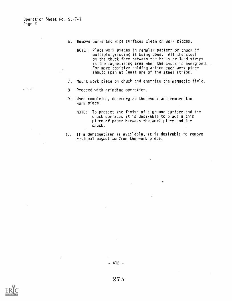
Operation Sheet No. SL-7-1Page 2
6. Remove burrs and wipe surfaces clean on work pieces.
NOTE: Place work pieces in regular pattern on chuck ifmultiple grinding is being done. All the steelon the chuck face between the brass or lead stripsis the magnetizing area when the chuck is energized.For more positive holding action each work pieceshould span at least one of the steel strips.
7. Mount work piece on chUck and energize the magnetic field.
8. Proceed with grinding operation.
9. When completed, de-energize the chuck and remove thework piece.
NOTE: To protect the finish of a ground surface and thechuck surfaces it is desirable to place a thinpiece of paper between the work piece and thechuck.
10. If a demagnetizer is available, it is desirable to removeresidual magnetism from the work piece.
- 412 -
275

OPERATION SHEET
Operation Sheet No. SL-7-2
HOW TO: Grind a Flat Surface
COURSE OF STUDY: Machine Shop Practice - Surface Grinder Operation
INTRODUCTAN: Although all grinding may be considered as su,-- ing
(in that a surface is being ground), the ineclassification of surface grinding involves 6- g a flat
surface. The primary objective of flat grir other than
flatness, is to produce a surface that is free irom waviness.Surface flatness can be checked by using a straight edge ordial indicator. aprn-teristics of the material being groundand finish gualitif, .sired will determine the type of wheel
and feed and spec:.
TOOLS ANDEQUIPMENT:
PROCEDURE:
Surface grinder, diamond wheel dresser, surface plate,magnetic chuck, straight edge and/or dial indicator, and
demagnetizer.
1. Mount the proper wheel on the spindle.
0 True and dress the wheel.
3. If a magnetic chuck is being used, "grind in" the chuck.
4. Mount work piece on the chuck or secure it to the table.
CAUTION: Check the holding power of the chuck by graspingit and trying to move it. If the work piece isbeing clamped to the table, be careful not towarp it.
S. Select proper feed and speed.
6. Adjust table stops.
7. Turn on spindle and coolant motors.
8. Dcwnfeed the wheel until it touches the highest point ofthe work piece.
NOTE: For rough grinding, a downfeed of .001 to .003inch per pass is used.
-413-
276

Operation Sheet No. SL-7-2Page 2
9. Adjust table to move work piece to starting position forrough cut.
10. Adjust wheel for depth of cut.
NOTE: To begin, follow the general principal that cross-feed increments should be .030 to .050 inch.
11. Adjust .table to move work piece to starting position forfinish cut.
NOTE: For finish grinding, a downfeed of .0001 to .0002inch is used. Dress wheel before taking a finishcut.
12. Adjust wheel for depth of finish.cut.
13. Before stopping the wheel turn off the coolant to allowthe coolant to be thrown from the wheel so that thewheel will remain in balance.
14. A demagnetizer (if available) should be used to demagnetizethe work piece.
NOTE: Some magnetic chuck models have a demagnetizingarrangement built into the chuck system.
- 414
277

OPERATION SHEET
Operation Sheet No. SL-7-3
HOW TO: True and Dress a Grinding Wheel
COURSE OF STUDY: Machine Shop Practice - Surface Grinder Operation
INTRODUCTION: One of the prerequisites for efficient and effective grindingis a properly dressed wheel. The dressing serves to exposenew and sharp cutting edges to the grinding surface. Animportant point to remember is that it is essential that thewheel be trued before dressing, that is, all points on theperiphery of the wheel must be concentric with the center ofthe wheel. The most common means of dressing a grinding wheelis by using a diamond imbedded in a steel shank.
TOOLS ANDEQUIPMENT: Surface grinder, diamond wheel dresser and safety glasses.
PROCEDURE: 1. Mount wheel to be used on spindle.
2. Mount diamond dresser on table or magnetic chuck.
NOTE: Some diamond holders have an arrow to indicatethe direction in which the holder should be placedon the table in relation to the wheel rotation.
3. Adjust the wheel height and table until the wheel isclose to the diamond.
4. In most applications the dresser is located about 1/4"to the left of the vertical center line of the wheel.
5. In the truing operation, lower the wheel until thehighest point on its periphery touches the diamond.
NOTE: Tnis prevents the diamond from taking too deep acut.
6. Cross feed the table so the diamond moves back and forthacrosS' the face of the wheel.
NOTE: If coolant is to be used in the grinding process,it should also be used when truing and dressing.
- 415 -
278
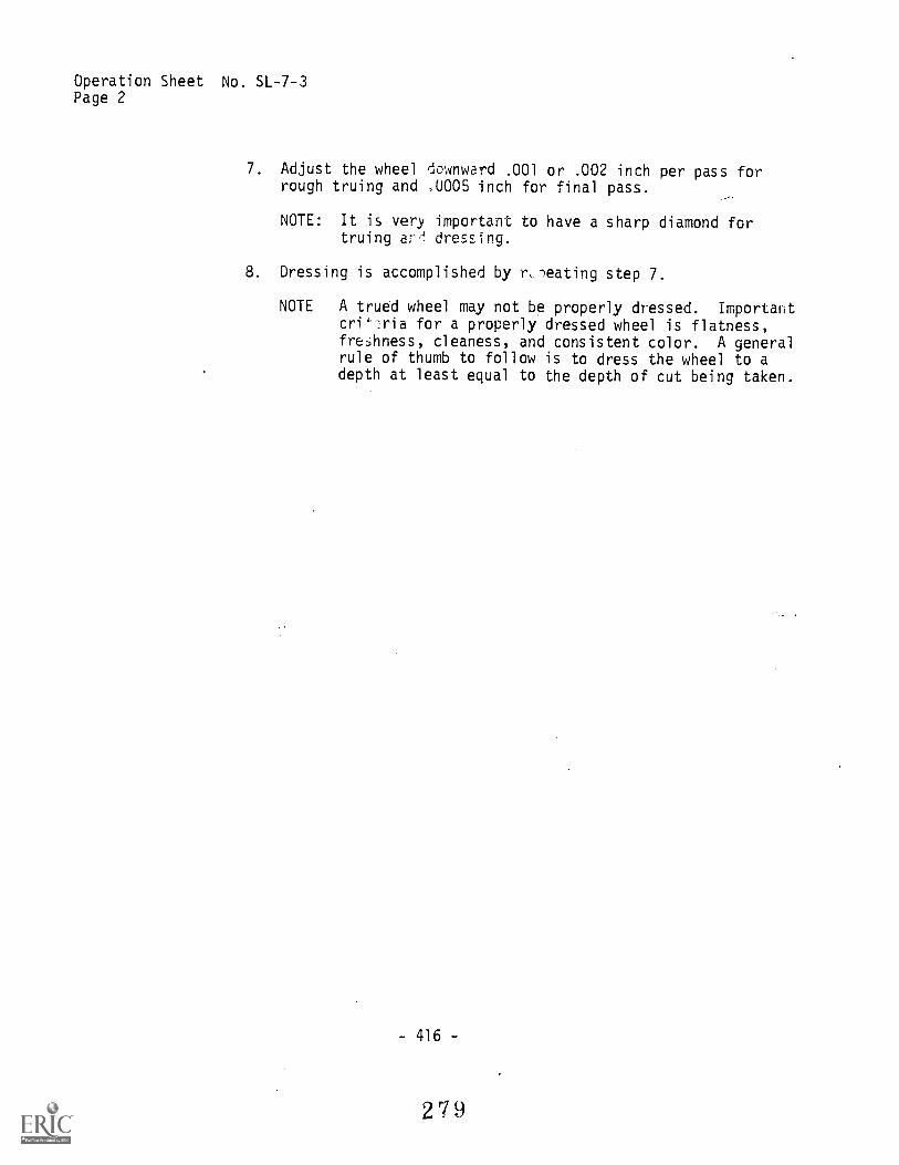
Operation Sheet No. SL-7-3Page 2
7. Adjust the wheel downward .001 or .002 inch per pass forrough truing and ,0005 inch for final pass.
NOTE: It is very important to have a sharp diamond fortruing arr-! dressing.
8. Dressing is accomplished by r,leating step 7.
NOTE A trued wheel may not be properly dressed. Importantcri4--ria for a properly dressed wheel is flatness,freAness, cleaness, and consistent color. A generalrule of thumb to follow is to dress the wheel to adepth at least equal to the depth of cut being taken.
- 416 -
279

OPERATION SHEET
Operation Sheet No. SL-7-4
HOW TO: Square Stock
COURSE OF C Machine Shop Practice - Surface Grinder Operation
INTRODUCTION: Squaring stock refers to the operation of machining materialinto a form having straight sides and right angles. Work thatrequires a good surface finish, in addition to being square,is done on the surface grinder. The material is usually roughmachined elsewhere before being delivered to the surfacegrinder for machining the final dimensios.
TOOLS ANDEQUIPMENT: Surface grinder, diamond dresser, and safety glasses.
PROCEDURE: 1. Inspect and clean surface of m,jnetic chuck.
2. File burrs from surface of work that is to come in contactwith the chuck.
3. Center the work on the chuci and energize the magnet movingthe lever to the "on" position.
NOTE: Check the holding power of the chuck by graspingthe work piece and trying to move it.
4. Adjust the table stops and table feeds if available.
NOTE: Consult with your instructor about setting tablefeed. Each make or model of a surface grinderdiffers somewhat in its adjustments.
5. Downfeed the grinding wheel until it touches the highestspot on the work piece.
r : The piece must be moved back and forth underthe grinding wheel, either by hand or by machine,traverse until the high sOot is found. The crossfeed, is available, should be set at this timl-f.
6. S:.art to traverse the table and feed the work piece forthe rough grind. Check prog-ess of cut tnen adjustcoolant if available.
- 417 -
280

Operaticl, Sheet No 7.4
Page 2
7. Continue feeding downward in increments of 0.001 inchuntil the grinding wheel covers the entire surface.The number of rough cuts depends upon the beginningsurface.
8. Dress wheel before the finish cut (refer to OperationSheet No. SL-7-3). Downfeed should be 0.0005 inch orless, depending upon the quality of surface finishdesired.
9. Before stopping the machine refer to Operation Sheet No.SL-7-3 if coolant is being used. Otherwise stop themachine.
10. Move work piece away from wheel and turn chuck lever co"off" position.
11. Remove work piece from chuck and file burrs.
12. Clean chuck surface.
13. Replace work piece on center of chu: with the finishedsurface down.
11. 2eactivate chuck magnet and check for holding power onthe work piece.
15. Repeat 5'..lps 5 through 12.
16. :i'e all .._Arrs.
flrished surface to a parallel or angle plate.-!,f2 sur., the top surface of the work piece is above thetop edge of the parallel or angle plate.
18. Use a surface gauge or an indicator to level the topsurface of the work piece in preparation for grinding.
19. Repeat steps 3, and 5 through 12.
20. File all burrs.
21. Repeat steps 13 and 14.
22. Repeat steps 5 through 11.
23. Clean entire machine and replace tools.
- 418 -
2 1

OPERATION SHEET
Operation Sheet No. SL-7-5
HOW Tu: Mount a Grinding Wheel
COURSE OF STUDY: Machine Shop Practice - Surface Grinder Operation
INTRODUCTION: To insure safe and efficient operation, a grinding wheel mustbe prLperly mounted. Extra caation during this sequence ofthe grinding operation will eliminate many difficulties thatcould possibly arise later.
TOOLS ANDEQUIPMENT:
PROCEDURE:
Surface grinder, grinding wheel, and safety glasses.
1. Before mounting, the wheel to be used should always be"ring" tested.
CAUTION: The "ring" test does not give positive proofthat the wheel is sound.
2. Carefully clean the su-faces of the wheel, spindle,blotters, and flanges that will come in contact with oneanother.
3. Mount inside flange and blotter.
NOTE: Always use blotters when mounting a wheel.
4. Mount grinding wheel.
CAUTION: The bore of the wheel should be the suediameter as the spindle or wheel adapter.
5. Mount outside blotter, fla-Th and nut.
CAUTION: Tighten the nut firmly, but not sc much as toset up excessive strain in the wheel.
6. Apply a "run-in" test by running the wheel at operating!.peed for about one minute before applying it to the work.
CAUTION: When applying this test, stand to one side andalways have the wheel guard in position.
7. The wheel should now be ready for truing and dressing.
1OTE: The wheel adapters on some grinders have provisionsfor statically balancing the whn:21,
- 419 -
2 `)"

OPERATION SHEET
Operation Sheet No. SL-8-1
HOW TO: Harden and Temper Tool Steel
COURSE OF STUDY: Machine Shop Practice - Heat Treatment
INTRODUCTION: Hardening is the process that changes the physical propertiesof steel by heating and rapid cooling. There is a higherpercentage of carbon in tool steel than in cold rolled steel.When steel has enough carbon, it becomes very hard after iti$ heated to a high temperature and cooled quickly in wateror oil.
Tempering is a process of reducing the degree of hardnessand strength and increasing the toughness. The temperingprocess always follows the hardening process.
TOOLS ANDEQUIPMENT: Safety glasses, heat treatment furnace, quench tank with
water,-suitalfle tongs, old file, asbestos gloves.
PROCEDURE: A. How to Harden a Piece of Carbon Tool Steel
1. Start up the furnace.
NOTE: If it is electric, set pyrometer to desiredtemperature, turn on main switch. If gas furnace,light the furnace and adjust the flame. Do notstand in front of or look into the furnace whenlighting it. Check Operator's Manual for otheroperating instructions on the furnace you areusing.
2. Select tongs that fit the work.
CAUTION: Wear safety glasses and asbestos gloves whenworking around the furnace. Be careful no,to pick up tongs or steel without firstchecking to see if they are hot.
3. Place work in furnace.
4. Close furnace door.
28,3
-421 -

Operation Sheet No. SL-8-1Page 2
5. Allow furnace to come up to correct hardening temperature.
NOTE: The critical point or critiCal temperature is thepoint at which the steel has the most desirablecharacteristics. When steel reaches this temper-ature, somewhere between 14.000 F and 1600° F, thecritical point is reached. The change is ideal tomake for a hard, strong material--if it is cooledquickly.
Preheat the jaws of the tongs before removingheated piece from furnace. This will prevent coldspots from appearing on the heated piece, iftouched by the cold jaws.
6. Remove the'work from the furnace and quench in wateror oil, depending upon the type of steel used, i.e.,water hardening or oil hardening steel.
NOTE: The heated piece should be dipped quickly into thewater. It is important that it be *Pied about oragitated in the water to prevent sLam pocketsfrom forming.
7. Test for hardness by trying to file the surface of thework. If the piece is hard, the file will slip over thesurface without scoring.
NOTE: Do not use a new file for testing hardness. Thecutting edges will be destroyed and the filebecomes useless.
B. How to Temper a Piece of Carbon Tool Steel
1. Polish the surface of the hardened piece with abrasivecloth.
NOTE: Cleaning of' the scale with abrasive cloth enlesyou to see Le tempering colors more clearly. Ifthe furnace has a pyrometer, step 1 may be omitted(refer to Information Sheet No. IL-8-5).
2 H4

Operation Sheet No. SL-L, 1
Page 3
2 Place piece in draw (tempering) furnace and close doc-.
NOTE: If furnace is a two chamber furnace, the lowerchamber is the draw (tempering) furnace (or lowheat furnace--temperature up to 800° F only).If the furnace is not a two chamber furnace,place piece in furnace and reduce heat to requiredtempering temperature.
3. When the proper heat or color has been reached, removedpieue from furnace and quickly quench.
4. Shut off furnace.
2 8
- 423

OPERATION SHEET
Operation Sheet No. SL-8-2
HOW TO: Caseharden Low Carbon Steel
COURSE OF STUDY: Machine Shop Practice - Heat Treatment
INTRODUCTION: Casehardening is a process of hardening the Titer surface orcase of low carbon steels. When adding a small amount ofcommercial hardening compound to the outer surface, it canbe heat treated to make the surface hara. The core or centerremains soft ant. auQtile.
TOOLS ANDEQUIPMENT: Furnace, asbestos gloves, safety glasses, tongs, quenching
tank or container, hardening compound.
PROCEDURE: 1. Start the furnace (refer to Operation Sheet No. SL-8-1for starting the furnace).
2. Place work in furnace, heat to salmon color (1650° F).
3. Grasp work with tongs, remove from furnace.
4. Coat with casehardening compound.
NOTE: One of two suggested nontoxic compounds, such as"Kasenit" or "Royal Hardening Powder," may be used.
5. Replace piece in furnace.
6 Reheat to a salmon color (1650° F).
7. Remove from furnace with tongs and quench in water.
8 Repeat the whole procedure if deeper penetration isdesired.
9 Shu4 flirnace.
NOTE: r. .-ork piece that is casehardened cannot be groundbecause the case or hardness penetration is notdeep enough. Grinding would remove the hardnessskin.
2 8 6
- 425 -

OPERATION SHEET
Operation Sheet No. SL-8-3
HOW TO: Anneal Tool Steel
COURSE OF STUDY: Machine Shop Practice - Heat Treatment
.INTRODUCTION: Annealing is the process of softening tool steel. This makesit easier to machine. The steel As heated above the criticaltemperature and cooled slowly.
TOOLS ANDEQUIPMENT: Furnace, asbestos gloves, tongs, and safety glasses.
PROCEDURE: 1. Start up furnace (refer to Operation Sneet No. SL-8-1for starting the furnace).
2. Select tongs that fit the work piece.
3. Place work in furnace.
. Close furnace door.
5. Heat work to critical point.
NOTE: The temperature required for annealing of steel isslightly above the critical point (the temperatureat which internal changes take place in thestructure of the metal). The critical point vaHes,of.course, with different steels. Some typicalannealing temperatures are: low-carbon steel,1650° F, and high speed steel, 1400° F. Thetemperatures should not be more than 500 to 75° Fabove the critical point.
6. Turn off the furnace, allowing the metal to cool slowly.
NOTE: A maximum cooling rate of 50° F per hour down to1000° F is suggested.
7. Return t.-)ngs, or any equipment that was used in theprocedure of annealing steel, to proper storage places.
287
- 427 -
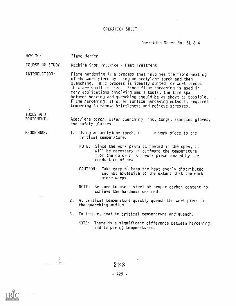
OPERATION SHEET
Operation Sheet No. SL-8-4
HOW TO: Flame Harc'n
COURSE OF STUDY: Machine Shop I- r.ice - Heat Treatment
INTRODUCTION: Flame hardening i!1 a process that involves the rapid heatingof the work piece by using an acetylene torch and thenquenching. This process is ideally suited for work piecesthlt are small in size. Since flame hardening is used inmany applications involving small tools, the time spanbetween heating and quenching should be as short as possible.Flame hardening, as other surface hardening methods, requirestempering to remove brittleness and relieve stresses.
TOOLS ANDEQUIPMENT: Acetylene torch, water quenching -q1k, tongs, asbestos gloves,
and safety glasses.
PROCEDURE: 1. Using an acetylene torch, .e work piece to thecritical temperature.
NOTE: Since the work pi s heated in the open, itwill be necessary to estimate the temperature.from the color work piece caused by theconduction of hea_.
CAUTION: Take care to keep the heat evenly distributedand.not excessive to the extent that the workpiece warps.
NOTE: Be sure to uSe-a steel Of proper carbon content toachieve the hardness desired.
2. At critical temperature quickly quench the work piece inthe quenching medium.
3. To temper, heat to critical temperature and quench.
NOTE: There is a significant difference between hardeningand tempering temperatures.
288429 -

Section 8
INFORMATION SHEETS
and
ASSIGNMENT SHEETS
Information Sheets supplement the job sheets and provide thestudent with related information necessary for completing theassignment jobs with the highest possible degree of understanding.The information units that will be stressed in this course are listed
in Section 5C.
Assignment Sheets supplement a textbook which will be used in
the course. These sheets provide the student with mental activitiesnecessary to learn the "knowing" that accompanies the "doing" of an
occupation.
The Information and Assignment Sheets should be prepared by each
instructor.
289
-431 -