document resume ed 083 372 general drafting. …... engineering drawing; ... lettering; engineering...
TRANSCRIPT
ED 083 372
TITLEINSTITUTIONREPORT NOPUB DATENOTE
AVAILABLE FROM
DOCUMENT RESUME
CE 000 302
General Drafting. Technical Manual.Department of the Army, Washington, D.C.TM-5-581A3 Oct 72223p.; This document supersedes TM-5-230, October 29,1962Superintendent of Documents, U.S. Government PrintingOffice, Washington, D.C. 20402 (488-579/19)
EDRS PRICE MF-$0.65 HC-$9.87DESCRIPTORS *Drafting; Engineering Drawing; Engineering Graphics;
Geometric Concepts; Instructional Materials; Manuals;*Military Personnel; Reprography; *TechnicalIllus'ration
IDENTIFIERS *Military Occupation Specialty; MOS
ABSTRACTThe manual provides instructional guidance and
reference material in the principles and procedures of generaldrafting and constitutes the primary study text for personnel indrafting as a military occupational specialty. Included isinformation on drafting equipment and its use; line weights,conventions and formats; lettering; engineering charts and graphs;geometrical construction; intersections and developments; multiviewprojections; pictorial drawing and sketching; dimension and notes;and methods of reproduction. The appendixes are lists of references,abbreviations, and illustrations and tables. There is also a subjectindex. (AG)
TM 5-581A
4,111I. k
(N) '11.? lie
Ii2).-, 'tr .'"'' 7r-,
k4, 1,+-
TECHNICAL MANUAL-..0SITRrii,tys
DUPL/cATE
(.....__, 4 JuN _.. 1
..la Copy-- :_:._... 1973
GENERAL
DRAFTING
U S DEPARTMENT OF HEALTHEDUCATION A WELFARENATIONAL INSTITUTE OF
EDUCATION
F F
HEADQUARTERS, DEPARTMENT OF THE ARMY
Cq.;',OBER 1972
TACO 19A
FILMED FROM BEST AVAILABLE COPY
}TECHNICAL MANUAL
5-581A
*TM 5-581A
HEADQUARTERSDEPARTMENT OF THE ARMY
WASHINGTON, D.C., 3 October 1972
GENERAL DRAFTING
Parestreph Page
CHAPTER 1. INTRODUCTION 1 -1 --1-6 1-1,1-2
2. DRAFTING EQUIPMENT AND ITS USE 2 -1 --2 -26 2 -1 --2 -19
3. LINE WEIGHTS, CONVENTIONS AND FORMA TS 3-1-3-9 3 -1 --3 -7
4. LETTERINI;Section I. Lettering requirements 4-1-4-6 4-1
II. Freehand lettering 4-7-4-12 4-3-4-9III. Mechanical lettering 4-13--4-15 4- 9,4 -10IV. Other lettering devices 4-16--4-18 4-11
CHAPTER 5. ENGINEERING CHARTS AND GRAPHSSection I. Graphic presentation of engineering data 5-1--5-3 5-1
7T, Technical charts 5-4-5-14 5-2-5-7III. Display charts 5- 15 -5 -21 5-7-5-12IV. Training aids 5-22-5-26 5-12,5-13
CHAPTER 6. GEOMETRICAL CONSTRUCTION 6-1-6-82 6-1-6-46Section I. Geometrical nomenclature 6-2-6-10 6-1-6-5
II. Straight line construction 6-A-6-51 6-5--6-22III. Curve line construction 6-52-6-82 6-24-6-46
CHAPTER 7. INTERSECTIONS AND DEVELOPMENTSSection I. Geometrical surfaces 7-1-7-4 7-1-7-11
II. Intersections 7-5-7-10 7-11-7-16III. Developments 7-11-7-19 "7-16-7-22
CHAPTER 8. MULTIVIEW PROJECTIONSSection I. Projections 8 -1 -8 -9 8-1-8-11
II. Sections 8-10--8-12 8- 15 -8 -21III. Auxiliary, and exploded views 8-13,8-14 8-23-8-27
CHAPTER 9. PICTORIAL DRAWING AND SKETCHINGSection I. Introduction 9-1, 9-2 9-1
II. Axonometric projection 9-3-9-14 9-1--9-6III. Oblique drawings 9-15-9-18 9-7- -9-9IV. Pictorial sketching 9-19-9-30 9-11-9-18
CHAPTER 10. DIMENSION AND NOTESSection I. Size description 10-1,10-2 10-1
II. Elements of dimensioning 10- 3 -10 -9 10-3--10-6III. Dimensioning methods 10-10--10-13 10-8-10-15IV. Notes 10-14,10-15 10-16
CHAPTER 11. REPRODUCTIONSection I. Introduction 11-1, 11-2 11-1
II. Production process _ 11-3-11-1 11-1-11-8APPENDIX A. REFERENCES _ _ A-1--A- A-1, A-2
B. ABBREVIATIONS B-1
C. LIST OF ILLUSTRATIONS AND TABLES
INDEX Index I
* This manual supersedes TM 5-210, 29 October 1962.
AGO 19A1
CHAPTER 1
INTRODUCTION
1-1. Purpose and Scope
a. This manual provides instructional guidanceand reference material in the principles and pro-cedures of general drafting. This manual is theprimary study text for personnel in this militaryoccupational specialty. The career pattern for sol-diers in this specialty is described in AR 611-201.
b. This manual contains the information re-quired in applying the general draftsman militaryoccupational specialty (MOS). It covers types ofdrafting equipment and their use; line weights,conventions, and formats; methods of lettering;preparation of charts and graphs; geometricalconstruction; surfaces and projections ; drawingand sketching; dimensioning drawings; and meth-ods of reproduction,
1-2. DutiesThe general draftsman's military occupationalspecialty is the basic entry IVIA.,S into the careerfields of construction draftsman, cartographicdraftsman, map compiler, illustrator, and modelmaker. The duties of the general draftsman in-clude but are not limited to the following. Hedraws a variety of general drafting details suchas diagrams, graphs, and charts; and assists per-sonnel engaged in construction drafting, carto-graphic drafting, map compilation, model makingand related art and drafting activities. He pre-pares graphic sections of organizational charts,statistical reports, and visual aids. He lettersdrawings, plans, artwork, and other related mate-rial by freehand or mechanical devices. He com-piles and enters information such as dimensions,specifications, and legends on appropriate sectionof drawings,
1 3. Drafting a Graphic Language
Engineer drawing has been called the graphic lan-guage of the engineer. It has definite rules ofusage to insure that is has the same meaningwherever it is used. Anyone who learns the rulescan read engineering drawings. Engineering
AGO HA
drawing must present information such as size,shape, location, material, and so forth, meetingcertain requirements and specifications. It mustbe presented in such a manner that the finishedproduct will be in accordance with the require-ments specified by the designer. Special tools, ordrawing instruments, are used to record this lan-guage with the necessary accuracy. These toolsare used by military draftsmen and engineers toproduce engineering drawings that conform toaccepted standards and practices.
1-4. Types of Engineer Construction
a. General construction performed by engineerconstruction units include such structures asheadquarters installations, housing facilities,workshops, hospitals, depots, protective shelters,storage and supply facilities, laundries, bakeries,refrigerated warehouses, training facilities, andmiscellaneous related projects.
b. Specialized construction projects include con-struction of new roads or upgrading of existingones ; building permanent and semi-permanentbridges ; construction and repair of railroads;planning and constructing military pipeline facili-ties; repair and construction of port facilities;and construction of airfields and heliports.
1-5. Principles of Military Construction
a. Construction should be accomplished withinthe allocated time using a minimum of materials,equipment and manpower. If new design is neces-sary, it should be simple and flexible and mustreflect available materials and level of training ofconstruction personnel. The permanency of anystructure erected must not exceed limits estab-lished by the theater commander.
b. Generally, a large project is completed inunits to allow the completed parts to be usedwhile construction continues. Underground orprotected sites should be considered in the con-struction of essential facilities. Improvisaticnsshould be used whenever possible to reduce mate-rial requirements. Facility planning should he of
1-1

such a nature as to avoid creating lucrative tar-gets ; dispersion of installations should be consid-ered at all times.
1-6. Comments
Users of this manual are encouraged to submitrecommended changes or comments to improvethe manual. Comments should be keyed to the
1 2
specific page, paragraph, and line of text in whichchange is recommended. Reasons should be pro-vided for each comment to insure complete un-derstanding and evaluation. Comments shouldbe prepared using DA Form 2028 (RecommendedChanges to Publications) and forwarded directto the Commandant, US Army Engineer School,Fort Belvoir, Virginia 22060.
AGO 19A
CHAPTER 2
DRAFTING EQUIPMENT AND ITS USE
2-1. Introductiona. This chapter illustrates and describes , the
equipment which helps the draftsman to performhis job more easily, swiftly, and accurately in therequired graphic language of the engineer. It isimportant to learn the correct use of these draw-ing instruments from the beginning. Proficiencywill come with continued practice, but it is essen-tial to start with the correct form. With practice,the skillful use of drawing instruments willbecome a habit.
b. For competence in drawing, accuracy andspeed are essential in military as well as commer-cial drafting. It should be realized from the begin-ning that a good drawing can be made as quicklyas a poor one.
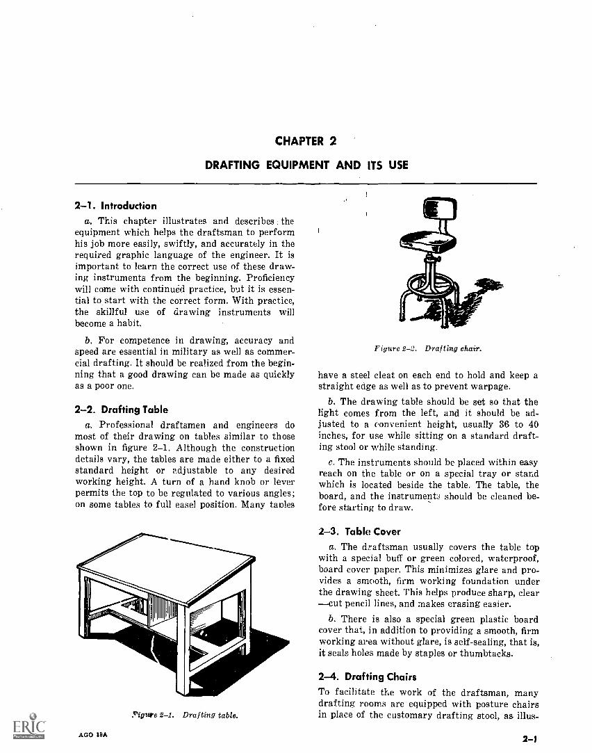
2-2. Drafting Tablea. Professional draftsmen and engineers do
most of their drawing on tables similar to thoseshown in figure 2-1. Although the constructiondetails vary, the tables are made either to a fixedstandard height or adjustable to any desiredworking height. A turn of a hand knob or leverpermits the top to be regulated to various angles;on some tables to full easel position. Many tables
Yigure 2-1. Drafting table.
AGO 18A
Figure 2-2. Drafting chair.
have a steel cleat on each end to hold and keep astraight edge as well as to prevent warpage.
b. The drawing table should be set so that thelight comes from the left, and it should be ad-justed to a convenient height, usually 36 to 40inches, for use while sitting on a standard draft-ing stool or while standing.
c. The instruments should be placed within easyreach on the table or on a special tray or standwhich is located beside the table. The table, theboard, and the instrument.; should be cleaned be-fore starting to draw.
2-3. Table Covera. The draftsman usually covers the table top
with a special buff or green colored, waterproof,board cover paper. This minimizes glare and pro-vides a smooth, firm working foundation underthe drawing sheet. This helps produce sharp, clearcut pencil lines, and makes erasing easier.
b. There is also a special green plastic boardcover that, in addition to providing a smooth, firmworking area without glare, is self-sealing, that is,it seals holes made by staples or thumbtacks.
2-4. Drafting ChairsTo facilitate the work of the draftsman, manydrafting rooms are equipped with posture chairsin place of the customary drafting stool, as illus-
2-1
N
L
K
T
TX'
J
7=4 eD .) 0
I IT
A
c=1:)
oDt=m
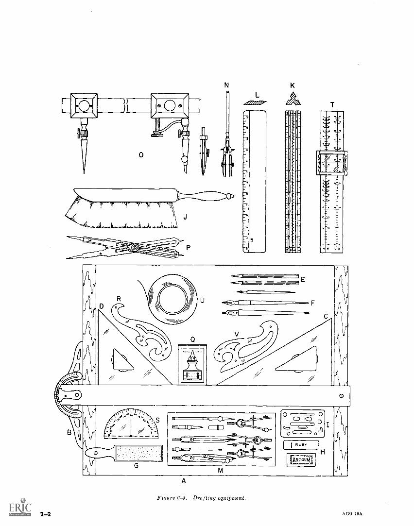
Figure 2-3. Drafting equipment.
2-2
O 0CD co D
o
AGO 19A
trated in figure 2-2. The posture chair has a freefloating back rest with a seat that can be raised orlowered to desired positions.
2-5. Drafting BoardThe drawing board (A, fig. 2-3) is used by drafts-men primarily for field work. It is commonlyfound in schools when drafting tables are notavailable. These boards are made of either whitepine or bass wood and come in a variety of sizes.
2-4. T-Squarea. The T-square (B, fig. 2-3) is used for draw-
ing horizontal lines and as a supporting straight-edge for triangles when vertical and slanted linesare to be drawn. The length ranges from 18 to 60inches. For maximum effectiveness, the T-squareshould extend the entire length of the draftingboard. The most popular T-squares have plastic orcelluloid edges which permit lines to be visibleunderneath the edge of the blade. Care should betaken to avoid marring the celluloid edges. Theworking edge of the T-square should never beused as a guide for a knife. The T-square must beperfectly square to be accurate, so care must betaken not to drop and damage it.
b. There is also a T-square with a protractor
I I UNDERSIDE OFT-SQUARE
ERROR EQUALSHALF OF THIS SPACE
Figure 2-4. Testing the T-square.
Figure 2-5. Parallel straightedge.
AGO 19A
head. An adjustable steel head is fastened to ablade usually made of stainless steel. The head hasa vernier corresponding to a protractor fastened tothe head so that angles may be set to fractions ofa degree.
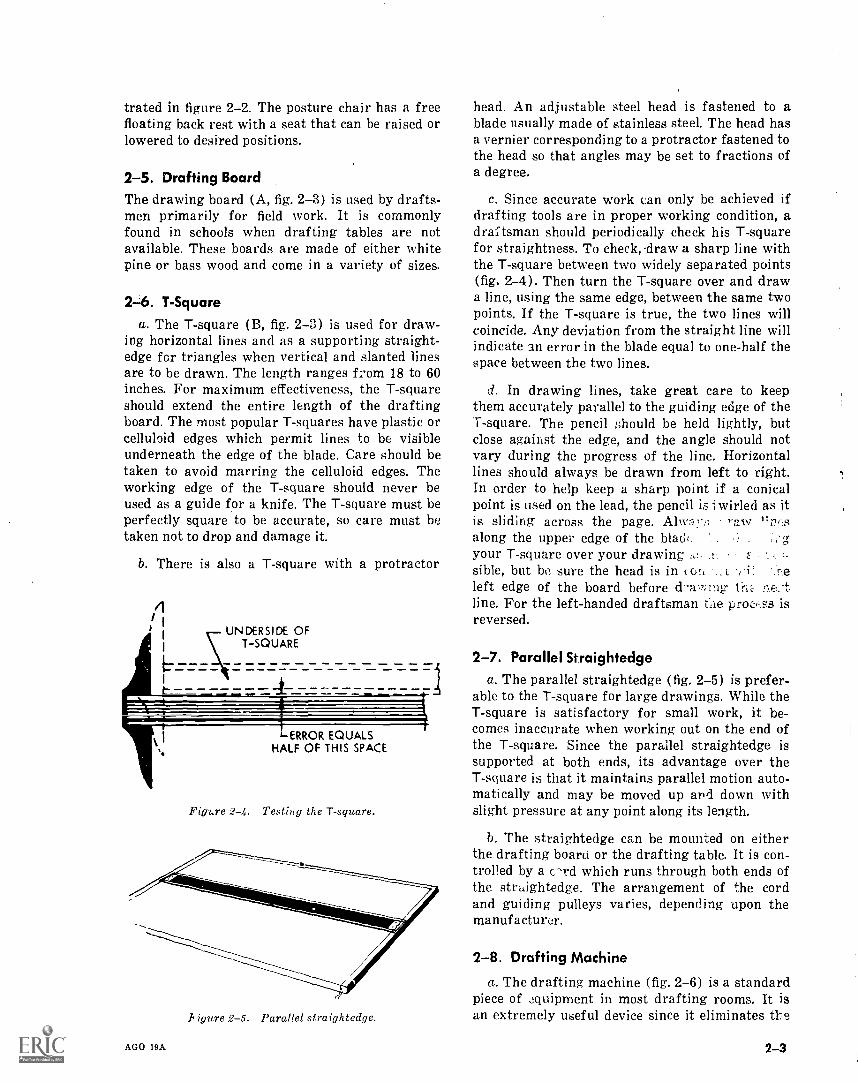
c. Since accurate work can only be achieved ifdrafting tools are in proper working condition, adraftsman should periodically check his T-squarefor straightness. To check, 'draw a sharp line withthe T-square between two widely separated points(fig. 2-4). Then turn the T-square over and drawa line, using the same edge, between the same twopoints. If the T-square is true, the two lines willcoincide. Any deviation from the straight line willindicate an error in the blade equal to one-half thespace between the two lines.
d. In drawing lines, take great care to keepthem accurately parallel to the guiding edge of theT-square. The pencil should be held lightly, butclose against the edge, and the angle should notvary during the progress of the line. Horizontallines should always be drawn from left to right.In order to help keep a sharp point if a conicalpoint is used on the lead, the pencil is twirled as itis sliding across the page. w 1;along the upper edge of the blad(:your T-square over your drawingsible, but be sure the head is in col, _E c-,e
left edge of the board before d-a,, ,ing ne.-tline. For the left-handed draftsman tie procrss isreversed.
2-7. Parallel Straightedgea. The parallel straightedge (fig. 2-5) is prefer-
able to the T-square for large drawings. While theT-square is satisfactory for small work, it be-comes inaccurate when working out on the end ofthe T-square. Since the parallel straightedge issupported at both ends, its advantage over theT-square is that it maintains parallel motion auto-matically and may be moved up and down withslight pressure at any point along its length.
b. The straightedge can be mounted on eitherthe drafting boaru or the drafting table. It is con-trolled by a c-rd which runs through both ends ofthe straightedge. The arrangement of the cordand guiding pulleys varies, depending upon themanufacturer.
2-8. Drafting Machine
a. The drafting machine (fig. 2-6) is a standardpiece of equipment in most drafting rooms. It isan extremely useful device since it eliminates the
2-3
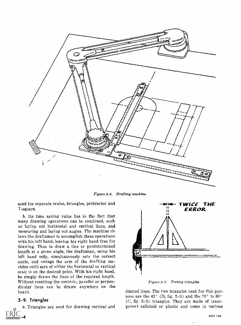
Figure 2-6. Drafting machine.
need for separate scales, triangles, protractor andT-square.
b. Its time saving value lies in the fact thatmany drawing operations can be combined, suchas laying out horizontal and vertical lines, andmeasuring and laying out aiwles. The machine al-lows the draftsman to accomplish these operationswith his left hand, leaving his right hand free fordrawing. Thus to draw a line or predeterminedlength at a given angle, the draftsman, using hisleft hand only, simultaneously sets the correctangle, and swings the arm of the drafting ma-chine until zero of either the horizontal or verticalscale is on the desired point. With his right hand,he simply draws the lines of the required length.Without resetting the controls, parallel or perpen-dicular lines can be drawn anywhere on theboard.
2-9. Trianglesa. Triangles are used for drawing vertical and
Po hal TWICE THEIt11 ERROR111
Figure 2-7. Testing triangles.
slanted lines. The two triangles used for this pur-pose are the 450 (D, fig. 2-3) and the :'0° to 60°(C, fig. 2-3) triangles. They are made of trans-parent celluloid or plastic and come in various
AGO 19A
sizes. The most common are the 8- or 10-inch forthe 30° to 6( ' and 6- or 8-inch for the 45°.
b. The straightness of a triangle is tested byplacing it against the T-square and drawing a ver-tical line (fig. 2-7). Then reverse the triangle anddraw another line along the same edge. If thetriangle is straight, the two lines will coincide; ifthey don't coincide, the error is half the resultingspace.
2-10. Adjustable TriangleThe adjustable triangle (fig. 2-8) is often pre-ferred by draftsmen instead of regular triangles.Since it has a built-in protractor it enables thedraftsman to draw any angle from 0° to 90°. Theadjustment arm is held firmly in place by a clampscrew, which also serves as a handle for lifting ormoving the instrument.
2-11. ProtractorProtractors (S, fig. 2-3) are used to measure andset off angles other than those measurable withthe draftsman's triangles. The protractor isusually numbered at 10° intervals. The smallestgraduation is 1/2 of a degree. It is semicricular inshape and is most commonly made of transparent
Figure 2-8. Adjustable triangle.
Figure 2-9. Use of protractor.
AGO 19A
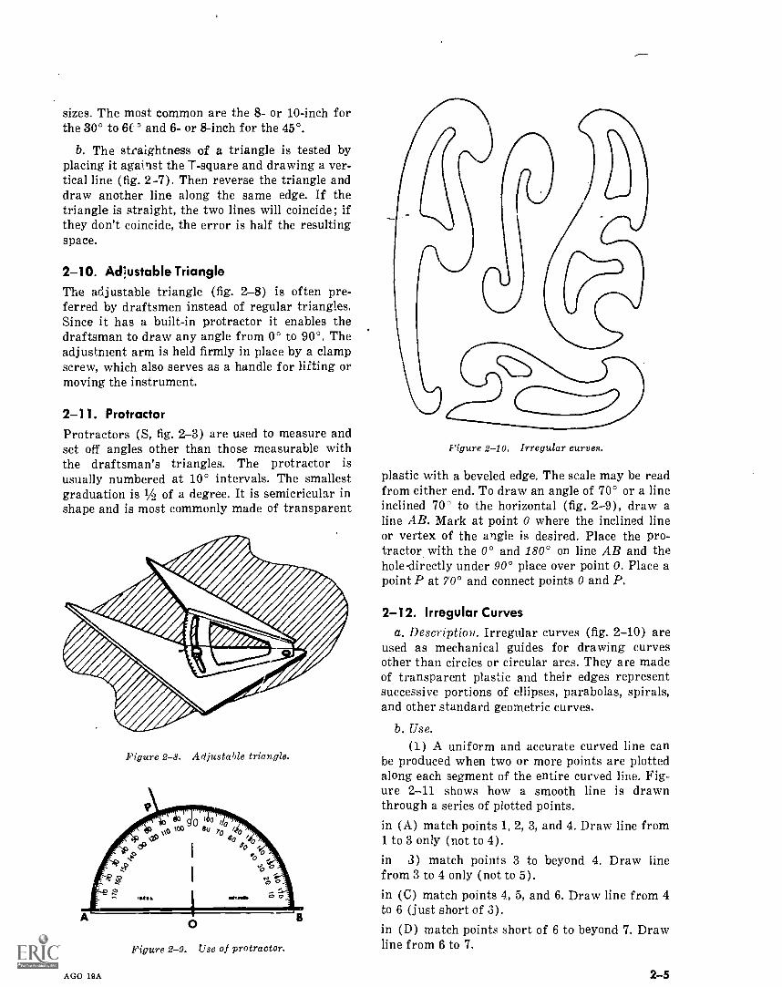
Figure 2-10. Irregular curves.
plastic with a beveled edge. The scale may be readfrom either end. To draw an angle of 70° or a lineinclined 70' to the horizontal (fig. 2-9), draw aline AB. Mark at point 0 where the inclined lineor vertex of the angle is desired. Place the pro-tractor with the 0° and 180° on line AB and thehole-directly under 90° place over point 0. Place apoint P at 70° and connect points 0 and P.
2-12. Irregular Curvesa. Description. Irregular curves (fig. 2-10) are
used as mechanical guides for drawing curvesother than circles or circular arcs. They are madeof transparent plastic and their edges representsuccessive portions of ellipses, parabolas, spirals,and other standard geometric curves.
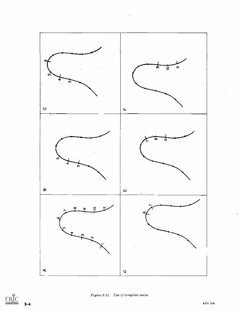
b. Use.(1) A uniform and accurate curved line can
be produced when two or more points are plottedalong each segment of the entire curved line. Fig-ure 2-11 shows how a smooth line is drawnthrough a series of plotted points.in (A) match points 1,2,3, and 4. Draw line from1 to 3 only (not to 4).in 3) match points 3 to beyond 4. Draw linefrom 3 to 4 only (not to 5).
in (C) match points 4, 5, and 6. Draw line from 4to 6 (just short of 3).in (D) match points short of 6 to beyond 7. Drawline from 6 to 7.
2-5
co
(.)
m
ti
<
tD
tico 01 o
o
Figure 2-11. Ube of irregular curve.
2-6 AGO 19A
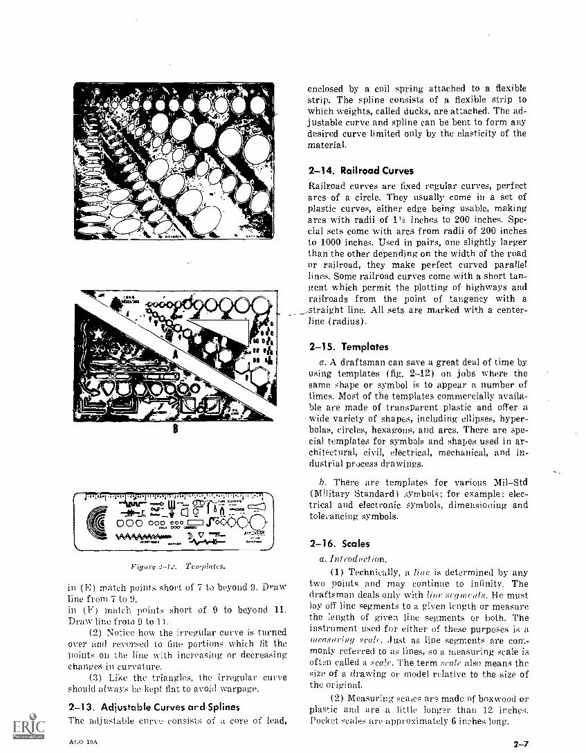
Figure 2-12. Templates.
in (E) match points short of 7 to beyond 9. Drawline from 7 to 9.in (F) match points short of 9 to beyond 11.Draw line from 9 to 11.
(2) Notice how the irregular curve is turnedover and reversed to fine portions which fit thepoints on the line with increasing or decreasingchanges in curvature.
(3) Like the triangles, the irregular curveshould always be kept fiat to avoid warpage.
2-13. Adjustable Curves and SplinesThe adjustable curve consists of a core of lead,
AGO 19A
enclosed by a coil spring attached to a flexiblestrip. The spline consists of a flexible strip towhich weights, called ducks, are attached. The ad-justable curve and spline can be bent to form anydesired curve limited only by the elasticity of thematerial.
2-14. Railroad CurvesRailroad curves are fixed regular curves, perfectarcs of a circle. They usually come in a set ofplastic curves, either edge being usable, makingarcs with radii of 1 inches to 200 inches. Spe-cial sets come with arcs from radii of 200 inchesto 1000 inches. Used in pairs, one slightly largerthan the other depending on the width of the roador railroad, they make perfect curved parallellines. Some railroad curves come with a short tan-gent which permit the plotting of highways andrailroads from the point of tangency with astraight line. All sets are marked with a center---line (radius).
2-15. Templatesa. A draftsman can save a great deal of time by
using templates (fig. 2-12) on jobs where thesame shape or symbol is to appear a number oftimes. Most of the templates commercially availa-ble are made of transparent plastic and offer awide variety of shapes, including ellipses, hyper-bolas, circles, hexagons, and arcs. There are spe-cial templates for symbols and shapes used in ar-chitectural, civil, electrical, mechanical, and in-dustrial process drawings.
b. There are templates for various MilStd(Military Standard) symbols; for example: elec-trical and electronic symbols, dimensioning andtolei.ancing symbols.
2-16. Scalesa. Introduction,
(1) Technically, a line is determined by anytwo points and may continue to infinity. Thedraftsman deals only with line segments. He mustlay off line segments to a given length or measurethe length of given line segments or both. Theinstrument used for either of these purposes is ameasuring ,scab. Just as line segments are com-monly referred to as lines, so a measuring scale isoften called a scale. The term scale also means thesize of a drawing or model relative to the size ofthe original.
(2) Measuring scales are made of boxwood orplastic and are a little longer than 12 inches.Pocket scales are approximately 6 inches long.
2-7
TRIANGULAR
TWO-BEVEL
OPPOSITE-BEVEL
FOUR-BEVEL
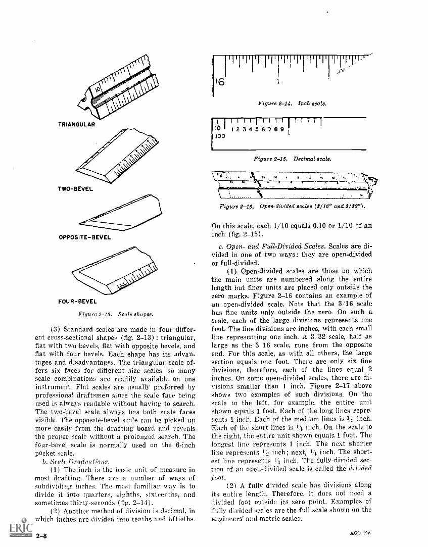
Figure 2-13. Scale shapes.
(3) Standard scales are made in four differ-ent cross-sectional shapes (fig. 2-13) : triangular,flat with two bevels, flat with opposite bevels, andflat with four bevels. Each shape has its advan-tages and disadvantages. The triangular scale of-fers six faces for different size scales, so manyscale combinations are readily available on oneinstrument. Flat scales are usually preferred byprofessional draftsmen since the scale face beingused is always readable without having to search.The two-bevel scale always lips both scale facesvisible. The opposite-bevel scale can be picked upmore easily from the drafting board and revealsthe proper scale without a prolonged search. Thefour-bevel scale is normally used on the 6-inchpocket scale.
b. Scale Graduations.(1) The inch is the basic unit of measure in
most drafting. There are a number of ways ofsubdividing inches. The most familiar way is todivide it into quarters, eighths, sixteenths, andsometimes thirty-seconds (fig. 2-14).
(2) Another method of division is decimal, inwhich inches are divided into tenths and fiftieths.
2-8
16
I I 11 I I i 1 II I I II I I 11 I I I I
Figure 2-14. Inch scale.
1 1 1 1 I 1 1 1 1 I 1 1 1 1 I
R: I 1 2 3 4 5 6 7 8 9100
.1r
Figure 2-15. Decimal scale.
Figure 2-16. Open-divided scales (3/16" and 3/32").
On this scale, each 1/10 equals 0.10 or 1/10 of aninch (fig. 2-15).
c. Open- and Full-Divided Scales. Scales are di-vided in one of two ways: they are open-dividedor full-divided.
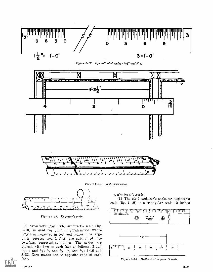
(1) Open-divided scales are those on whichthe main units are numbered along the entirelength but finer units are placed only outside thezero marks. Figure 2-16 contains an example ofan open-divided scale. Note that the 3/16 scalehas fine units only outside the zero. On such ascale, each of the large divisions represents onefoot. The fine divisions are inches, with each smallline representing one inch. A 3/32 scale, half aslarge as the 3 16 scale, runs from the oppositeend. For this scale, as with all others, the largesection equals one foot. There are only six finedivisions, therefore, each of the lines equal 2
inches. On some open-divided scales, there are di-visions smaller than 1 inch. Figure 2-17 aboveshows two examples of such divisions. On thescale to the left, for example, the entire unitshown equals 1 foot. Each of the long lines repre-sents 1 inch.. Each of the medium lines is 1/..! inch.Each of the short lines is 14 inch. On the scale tothe right, the entire unit shown equals 1 foot. Thelongest line represents 1 inch. The next shorterline represents 10 inch; next, 1/1. inch. The short-est line represents 11it inch. The fully-divided sec-tion of an open-divided scale is called the dividedfoot.
(2) A fully divided scale has divisions alongits entire length. Therefore, it does not need adivided foot outside its zero point. Examples offully divided scales are the full scale shown on theengineers' and metric scales.
AGO 19A
111111111111111111111111111111111111r11111
29 6 3
1 u1-2 = 11-0"
0 3 6 9
3u_ II- ou
Figure 2-17. Open-divided scales (11/2" and 8").
AG.T.les J 4.4 0,1101.1 /WV,: f.-.V17 W1A y t. 711,1 21 Lt. r
1111111"21511115 2112 1h lbA
1111111 AIM I I I I IN MI NM I I It
Figure 2-18. Architect's scale.
Figure 2-19. Engineer's scale.
d. Architect's Seal J. The architect's scale (fig.2-18) is used for building construction wherelength is measured in feet and inches. The largeunits, representing 1 foot, are subdivided intotwelfths, representing inches. The scales arepaired, with two on each face as follows: 3 and1/2 ; 1 and 1/4 ; andand 3/8; 1/4, and 1/8; 3/16 and3/32. Zero marks are at opposite ends of eachface.
AGO 19A
16
e. Engineer's Scale.(1) The civil engineer's scale, or engineer's
scale (fig. 2-19) is a triangular scale 12 inches
4T
I I 1,11 1 218
26 I 214 22 20I
0 I 2 3 4 5
Figure 2-20. Mechanical engineer's scale.
2-9
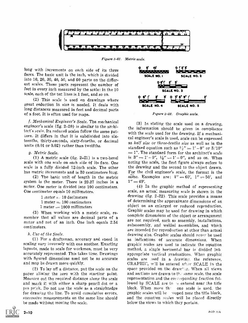
Figure 2-21. Metric scale.
long with increments on each side of its threefaces. The basic unit is the inch, which is dividedinto 10, 20, 30, 40, 50, and 60 parts on the differ-ent scales. These parts represent the number offeet in every inch measured by the scale: in the 10scale, each of the ten lines is.1 foot, and so on.
(2) This scale is used on drawings wheregreat reduction in size is needed. It deals withlong distances measured in feet and decimal partsof a foot. It is often used for maps.
f. Mechanical Engineer's Scale. The mechanicalengineer's scale (fig. 2-20) is similar to the archi-tect's scale. Its reduced scales follow the same pat-tern. It differs in that it is subdivided into six-teenths, thirty-seconds, sixty-fourths, or decimalunits (0.01 or 0.02) rather than twelfths.
g. Metric Scale.(1) A metric scale (fig. 2-21) is a two-bevel
scale with one scale on each side of its face. Onescale is a fully divided 12-inch scale. The otherhas metric increments and is 30 centimeters long.
(2) The basic unit of length in the metricsystem is the meter. There is 39.37 inches in ameter. One meter is divided into 100 centimeters.One centimeter equals 10 millimeters.
1 ineter 10 decimeters1 meter , 100 centimeters
1 meter 1000 millimeters(3) When working with a metric scale, re-
member that all values are decimal parts of ameter and not of an inch. One inch equals 2.54centimeters.
h. Use of the Scale.(1) For a draftsman, accuracy and speed in
scaling vary inversely with one another. Exactinglayouts, made to scale for workmen, must be veryaccurately represented. This takes time. Drawingswith figured dimensions need not be as accurateand may be drawn more quickly.
(2) To lay off a distance, put the scale on thepaper alining the zero with the starting point.Measure out the required distance along the scaleand mark it with either a sharp pencil dot or apin prick. Do not use the scale as a straightedgefor drawing the line. To avoid cumulative errors,successive measurements on the same line shouldbe made without moving the scale.
2-10
O 10' 0 r 2''
SCALE NO. I SCALE NO. 2
O de 2' 3'
SCALE NO. 3
0 fa 11 2' 3' 0 r le S. le 2'
SCALE NO. 4 SCALE NO: 5
Figure 2-22. Graphic scale.
(3) In stating the scale used on a drawing,the information should be given in compliancewith the scale used for the drawing. If a mechani-cal engineer's scale is used, scale can be expressedas half size or three-tenths size as well as in thestandard equation such as 1Z," = 1' 0" or 3/10"
1 ". The standard form for the architect's scaleis 3", 1' 0", 1/4" = r 0", and so on. Whennoting the scale, the first figure always refers tothe drawing and the second to the object drawn.For the civil engineer's scale, the format is thesame. Examples are: 1" = 60', 1" 50', and1" = 40'.
(4) In the graphic method of representingscale, an actual measuring scale is shown in thedrawing (fig. 2-22). This scale provides a meansof determining the approximate dimensions of anobject on an enlarged or reduced reproduction.Graphic scales may be used for drawing in whichcomplete dimensions of the object or arrangementare not required, such as assembly, installations,subassembly, and welded assemblies, and whichare intended for reproduction at other than actualdrawing size. Graphic scales should never be usedas indications of accurate dimensions. Whengraphic scales are used to indicate the equationmethod, 2.. single horizontal bar is divided int(appropriate vertical graduations. When graphicscales are used in a drawing. the reference,GRAPHIC, will be entered afIor SCALE in thespace provided on the dra'-_g. When all viewsand sections are drawn to th, same scale, the scalerepresentation and the corresponding fraction fol-lowed by SCALE are to 'e entered near ;:he titleblock, When more th: one scale is used. thegraphic scales will be ouped near the title block,and the equation scales will be placed directlybelow the views to which they pertain.
AGO 19A
E0
9
8
7
6
5
43
2
1
05 0 Cm
H-Millimeters
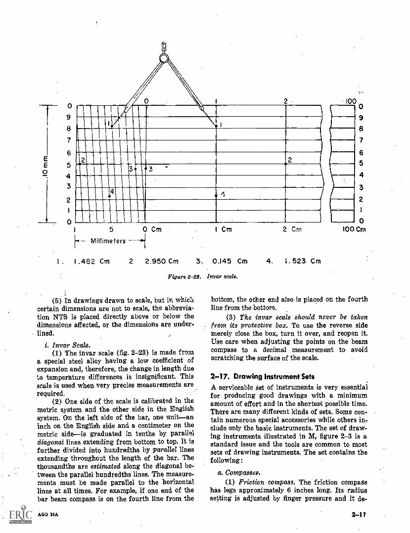
I . 1 .482 Cm 2 2.950 Cm
1 Cm 2 Cm
3. 0.145 Cm 4. 1. 523 Cm
Figure 2-23. Invar scale.
(5) In drawings drawn to scale, but in whichcertain dimensions are not to scale, the abbrevia-tion NTS is placed directly above or below thedimensions affected, or the dimensions are under-lined.
i. Invar Scale.(1) The invar scale (fig. 2-23) is made from
a special steel alloy having a low coefficient ofexpansion and, therefore, the change in length dueto temperature differences is insignificant. Thisscale is used when very precise measurements arerequired.
(2) One side of the scale is calibrated in themetric system and the other side in the Englishsystem. On the left side of the bar, one unitaninch on the English side and a centimeter on themetric sideis graduated in tenths by paralleldiagonal lines extending from bottom to top. It isfurther divided into hundredths by parallel linesextending throughout the length of the bar. Thethousandths are estimated along the diagonal be-tween the parallel hundredths lines. The measure-ments must be made parallel to the horizontallines at all times. For example, if one end of thebar beam compass is on the fourth line from the
AGO 19A
100o9
8
7
6
5
4
3
2
1
0100 Cm
bottom, the other end also is placed on the fourthline from the bottom.
(3) The invar scale should never be takenfrom its protective box. To use the reverse sidemerely close the box, turn it over, and reopen it.Use care when adjusting the points on the beamcompass to a decimal measurement to avoidscratching the surface of the scale.
2-17. Drawing Instrument SetsA serviceable set of instruments is very essentialfor producing good drawings with a minimumamount of effort and in the shortest possible time.There are many different kinds of sets. Some con-tain numerous special accessories while others in-elude only the basic instruments. The set of draw-ing instruments illustrated in M, figure 2-3 is astandard issue and the tools are common to mostsets of drawing instruments. The set contains thefollowing:
a. CompasSes.(1) Friction compass. The friction compass
has legs approximately 6 inches long. Its radiussetting is adjusted by finger pressure and it de-
2-11
pends on friction at the pivot joint to maintain itssetting. It can be used to draw radii up to 5 inchesand when using the extension bar up to 9 inches.
(2) Bow compass. There are two types ofbow compasses : one has a center thumbscrew be-tween the legs and the other has a side thumb-screw outside one of the legs. The small bow com-pass can be used for circle arcs up to 1-inch ra-dius.
(3) Drop compass. The drop compass is de-signed for the drawing of small accurate circles.The center rod contains the needlepoint and re-mains stationary while the tube carrying the penor pencil revolves around it.
(4) Beam compass. A beam compass (0, fig.2-3) consists of a long bar with a needlepointattachment at one end and pencil or pen attach-ment at the other. All of the attachments are ad-justable, to permit the drawing of large circleseasily.
(5) Use of the compass.(a) The compass, with pencil and inking
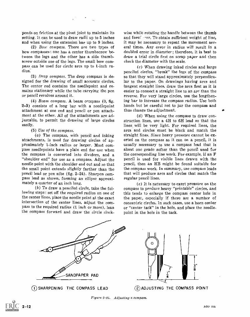
attachments, is used for drawing circles of ap-proximately 1-inch radius or larger. Most com-pass needlepoints have a plain end for use whenthe compass is converted into dividers, and a"shoulder end" for use as a compass. Adjust theneedle point with the shoulder end out and so thatthe small point extends slightly farther than thepencil lead or pen nibs (fig. 2-24). Sharpen com-pass lead as shown, forming an ellipse approxi-mately a quarter of an inch long.
(b) To draw a penciled circle, take the fol-lowing steps : set off the required radius on one ofthe center lines, place the needle point at the exactintersection of the center lines, adjust the com-pass to the required radius (1 inch or more), leanthe compass forward and draw the circle clock-
2-12
wise while rotating the handle between the thumband fore ,,er. To obtain sufficient weight of line,it may be necessary to repeat the movement sev-eral times. Any error in radius will result in adoubled error in diameter ; therefore, it is best todraw a trial circle first on scrap paper and thencheck the diameter with the scale.
(c) When drawing inked circles and largepenciled circles, "break" the legs of the compassso that they will stand approximately perpendicu-lar to the paper. On drawings having arcs andtangent straight lines, draw the arcs first as it iseasier to connect a straight line to an are than thereverse. For very large circles, use the lengthen-ing bar to increase the compass radius. Use bothhands but be careful not to jar the compass andthus change the adjustment.
(d) When using the compass to draw con-struction lines, use a 4H to 6H lead so that thelines will be very light. For required lines, thearcs and circles must be black and match thestraight lines. Since heavy pressure cannot be ex-erted on the compass as it can on a pencil, it isusually necessary to use a compass lead that isabout one grade softer than the pencil used forthe corresponding line work. For example, if an Fpencil is used for visible lines drawn with thepencil, then an HB might be found suitable forthe compass work. In summary, use compass leadsthat will produce arcs and circles that match theregular pencil lines.
(e) It is necessary to exert pressure on thecompass to produce heavy "printable" circles, andthis tends to enlarge the compass center hole inthe paper, especially if there are a number ofconcentric circles. In such cases, use a horn centeror "center tack" in the hole, and place the needle-point in the hole in the tack.
SANDPAPER PAD
()SHARPENING THE COMPASS LEAD ®ADJUSTING THE COMPASS POINT
Figure 2-24. Adjusting a compass.
AGO 19A
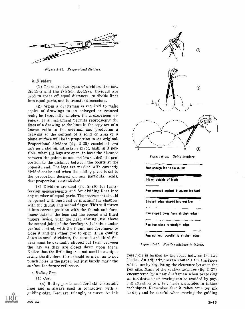
Figure 2-25. Proportional dividers.
b. Dividers.(1) There are two types of dividers : the bow
dividers and the friction d:viders. Dividers areused to space off, equal distances, to divide linesinto equal parts, and to transfer dimensions.
(2) When a draftsman is required to makecopies of drawings to an enlarged or reducedscale, he frequently employs the proportional di-viders. This instrument permits reproducing thelines of a drawing so the lines in the copy are of aknown ratio to the original, and producing adrawing so the content of a solid or area of aplane surface will be in proportion to the original.Proportional dividers (fig. 2-25) consist of twolegs on a sliding, adjustable pivot, making it pos-sible, when the legs are open, to have the distancebetween the points at one end bear a definite pro-portion to the distance between the points at theopposite end. The legs are marked with correctlydivided scales and when the sliding pivOt is set tothe proportion desired on any particular scale,that proportion is established.
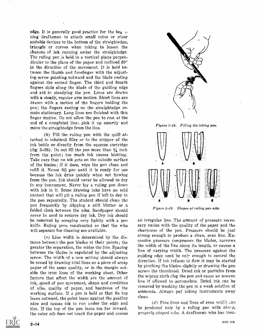
(3) Dividers are used (fig. 2-26) for trans-ferring measurements and for dividing lines intoany number of equal parts. The instrument shouldbe opened with one hand by pinching the chamferwith the thumb and second finger. This will throwit into correct position with the thumb and fore-finger outside the legs and the second and thirdfingers inside, with the head resting just abovethe second joint of the forefinger. It is thus underperfect control, with the thumb and forefinger toclose it and the other two to open it. In comingdown to small divisions, the second and third fin-gers must be gradually slipped out from betweenthe legs as they are closed down upon them.Notice that the little finger is not used in manipu-lating the dividers. Care should be given as to notpunch holes in the paper, but just barely mark thesurface for future reference.
c. Ruling Pen.(1) Use.
(a) Ruling pen is used for inking straightlines and is always used in connection with apriding edge, T-square, triangle, or curve. An ink
AGO 19A
0
Figure 2-26. Using dividers.
Not enough Ink to finish line
IMMINP1111111111.11111111AllInk on outside of blade
Pen pressed against T-square too hard
Straight edge slipped into wet line
Pen sloped away from straight edge
Pen too close to straight edge
Pen not kept parallel to straight edge
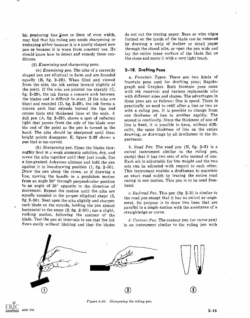
Figure 2-27. Routine mishaps in inking.
reservoir is formed by the space between the twoblades. An adjusting screw controls the thicknessof the line by regulating the clearance between thepen nibs. Many of the routine mishaps (fig. 2-27)encountered by a new draftsman when preparingan ink drawiTiz or tracing can be avoided by pay-ing attention to a fe; basic principles in inkingtechniques. Remember that it takes time for inkto dry ; and be careful when moving the guiding
2-13
edge. It is generally good practice for the be i-ning draftsman to attach small coins or othersuitable devices to the bottom of the straightedge,triangle or curves when inking to lessen thechances of ink running under the straightedge.The ruling pen is held in a vertical plane perpen-dicular to the plane of the paper and inclined 30°in the direction of the movement. It is held be-tween the thumb and forefinger with the adjust-ing screw pointing outward and the blade restingagainst the second finger. The third and fourthfingers slide along the blade of the guiding edgeand aid in steadying the pen. Lines are drawnwith a steady, regular arm motion. Short lines aredrawn with a motion of the fingers holding thepen ; the fingers resting on the straightedge re-main stationary. Long lines are finished with thisfinger motion. Do not allow the pen to rest at theend of a completed line; pick it up smartly andmove the straightedge from the line.
(b) Fill the ruling pen with the quill at-tached to inkstand filler or to the stopper of theink bottle or directly from the squeeze cartridge(fig. 2-28). Do not fill the pen more than 1/4 inchfrom the point; too much ink causes blotting.Take care that no ink gets on the outside surfaceof the blades ; if it does, wipe the pen clean andrefill it. Never fill pen until it is ready for usebecause the ink dries quickly when not flowingfrom the pen. Ink should never be allowed to dryin any instrument. Never lay a ruling pen downwith ink in it. Some drawing inks have an acidcontent that will pit a ruling pen if left to dry inthe pen repeatedly. The student should clean thopen frequently by slipping a stiff blotter or afolded cloth between the nibs. Sandpaper shouldnever be used to remove dry ink. Dry ink shouldbe removed by scraping very lightly with a penknife. Ruling pens constructed so that the nibswill separate for cleaning are available.
(c) Line width is determined by the dis-tance between the pen blades at their points ; thegreater the separation, the wider the line. Spacingbetween the blades is regulated by the adjustingscrew. The width of a new setting should alwaysbe tested by drawing trial lines on a piece of scrappaper of the same quality, or in the margin out-side the trim lines of the working sheet. Otherfactors that affect the width are the amount ofink, speed of pen movement, shape and conditionof nibs, quality of paper, and hardness of theworking surface. If a pen is held so that its topleans outward, the point leans against the guidingedge and causes ink to run under the edge andblot. If the top of the pen leans too far inward,the outer nib does not touch the paper and causes
2-14
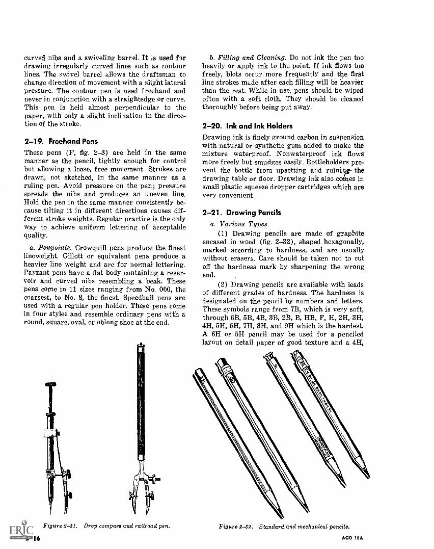
Figure 2-28. Filling the inking pen.
I
Figure 2-29. Shapes of ruling pen nibs.
an irregular line. The amount of pressure neces-sary varies with the quality of the paper and thesharpness of the pen. Pressure should be juststrong enough to produce a clean, even line. Ex-cessive pressure compresses the blades, narrowsthe width of the line along its length, or causes aline of varying width. The pressure against theguiding edge need be only enough to control thedirection. If ink refuses to flow it may be startedby pinching the blades slightly or drawing the penacross the thumbnail. Dried ink or particles fromthe wiping cloth clog the pen and cause an unevenline if allowed to accumulate. Dried ink can beremoved by washing the pen in a weak solution ofammonia. Always put inking instruments awayclean.
(d) Fine lines and lines of even width canbe produced only by a ruling pen with sharp,properly shaped nibs. A draftsman who has trou-
AGO 19A
ble producing fine alines or lines of even width,may find that his ruling pen needs sharpening orreshaping either because it is a poorly shaped newpen or because it is worn from constant use. Heshould know how to detect and remedy these con-ditions.
(2) Examining and sharpening pens.(a) Examining pen. The nibs of a correctly
shaped pen are elliptical in form and are foundedequally (B, fig. 2-29). When filled and viewedfrom the side, the ink arches inward slightly atthe point. If the nibs are pointed too sharply (C,fig. 2-29), the ink forms a concave arch betweenthe blades and is difficult to start. If the nibs areblunt and rounded (D, fig. 2-29), the ink forms aconvex arch that extends beyond the tips andcauses blots and thickened lines at the ends. Adull pen (A, fig. 2-29), shows a spot of reflectedlight that passes from the side of the blade overthe end of the point as the pen is turned in thehand. The nibs should be sharpened until thesebright points disappear. E, figure 2-29 shows apen that is too curved.
(b) Sharpening pen. Clean the blades thor-oughly first in a weak ammonia solution, dry, andscrew the nibs together until they just touch. Usea fine-grained Arkansas oilstone and hold the penagainst it in line-drawing position (1, fig. 2-30).Draw the pen along the stone, as if drawing aline, moving the handle in a pendulum motionfrom an angle 30° through perpendicular positionto an angle of 30° opposite to the direction ofmovement. Repeat the motion until the nibs areequally rounded in the proper elliptical shape (3,fig. 2-30). Next open the nibs slightly and sharpeneach blade on the outside, holding the pen almosthorizontal to the stone (2, fig. 2-30) ; use a slight,rocking motion, following the contour of theblade. Test the pen at intervals to see that the inkflows easily without blotting and that the blades
do not cut the tracing paper. Burs or wire edgesformed on the inside of the blade can be removedby drawing a strip of leather or detail paperthrough the closed nibs, or open the pen wide andlay the entire inner surface of the blade flat onthe stone and move it with a very light touch.
2-18. Drafting Pens
a. Fountain Types. There are two kinds offountain pens used for drafting pens; Rapido-graph and Graphos. Both fountain pens comewith ink reservoir and various replaceable nibswith different sizes and shapes. The advantages inthese pens are as follows: One is speed. There ispractically no need to refill after a line or two aswith a ruling pen. It is possible to change fromone thickness of line to another rapidly. Thesecond is continuity. Since the thickness of size ofline is fixed, it is possible to have, without diffi-culty, the same thickness of line on the entiredrawing, or drawings by all draftsmen in the de-partment.
b. Road Pen. The road pen (N, fig. 2-3) is aswivel instrument similar to the ruling pen,except that it has two sets of nibs instead of one.Each nib is adjustable for line weight and the twosets can be adjusted with respect to each other.This instrument enables a draftsman to maintainan exact road width by tracing the entire roadcasing in one motion. This pen is to be used free-hand.
c. Railroad Pen. This pen (fig. 2-3) is similar tothe road pen except that it has no swivel an ange-ment. Its purpose is to draw two lines that areparallel in a single motion with the assistance of astraightedge or curve.
d. Contour Pen. The contour pen (or curve pen)is an instrument similar to the ruling pen with
Figure 2-30. Sharpening the inking pen.
AGO 19A
o
2-15
curved nibs and a swiveling barrel. It Is used f,rdrawing irregularly curved lines such as contourlines. The swivel barrel allows the draftsman tochange direction of movement with a slight lateralpressure. The contour pen is used freehand andnever in conjunction with a straightedge or curve.This pen is held almost perpendicular to thepaper, with only a slight inclination in the direc-tion of the stroke.
2-19. Freehand PensThese pens (F, fig. 2-3) are held in the samemanner as the pencil, tightly enough for controlbut allowing a loose, free movement. Strokes aredrawn, not sketched, in the same manner as aruling pen. Avoid pressure on the pen; Pressurespreads the nibs and produces an uneven line.Hold the pen in the same manner consistently be-cause tilting it in different directions causes dif-ferent stroke weights. Regular practice is the onlyway to achieve uniform lettering of acceptablequality.
a. Penpoints. Crowquill pens produce the finestlineweight. Gillott or equivalent pens produce aheavier line weight and are for normal lettering.Payzant pens have a flat body containing a reser-voir and curved nibs resembling a beak. Thesepens come in 11 sizes ranging from No. 000, thecoarsest, to No. 8, the finest. Speedball pens areused with a regular pen holder. These pens comein four styles and resemble ordinary pens with around, square, oval, or oblong shoe at the end.
Figure 2-41. Drop compass and railroad pen.
2-16
b. Filling and Cleaning. Do not ink the pen tooheavily or apply ink to the point. If ink flows toofreely, blots occur more frequently and the firstline strokes made after each filling will be heavierthan the rest. While in use, pens should be wipedoften with a soft cloth. They should be cleanedthoroughly before being put away.
2-20. Ink and Ink HoldersDrawing ink is finely ground carbon in suspensionwith natural or synthetic gum added to make themixture waterproof. Nonwaterproof ink flowsmore freely but smudges easily. Bottleholders pre-vent the bottle from upsetting and ruinilgg- thedrawing table or floor. Drawing ink also canes insmall plastic squeeze dropper cartridges which arevery convenient.
2-21. Drawing Pencilsa. Various Types.
(1) Drawing pencils are made of graphiteencased in wood (fig. 2-32), shaped hexagonally,marked according to hardness, and are usuallywithout erasers. Care should be taken not to cutoff the hardness mark by sharpening the wrongend.
(2) Drawing pencils are available with leadsof different grades of hardness. The hardness isdesignated on the pencil by numbers and letters.These symbols range from 7B, which is very soft,through 6B, 5B, 4B, 3B, 2B, B, HB, F, H, 2H, 3H,4H, 5H, 6H, 7H, 8H, and 9H which is the hardest.A 6H or 5H pencil may be used for a penciledlayout on detail paper of good texture and a 4H,
Figure 2-82. Standard and mechanical pencils.
AGO 19A
0 -4403=1O
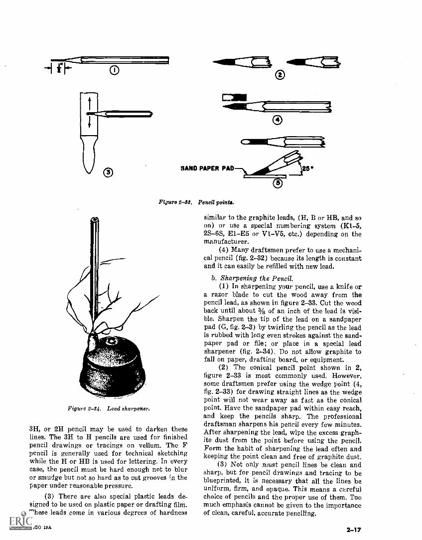
SAND PAPER PAD I 25Figure 2-33. Pencil points.
7ZYvf.'
Figure 2-34. Lead sharpener.
3H, or 2H pencil may be used to darken theselines. The 3H to H pencils are used for finishedpencil drawings or tracings on vellum. The Fpencil is generally used for technical sketchingwhile the H or HB is used for lettering. In everycase, the pencil must be hard enough not to bluror smudge but not so hard as to cut grooves ;n thepaper under reasonable pressure.
(3) There are also special plastic leads de-signed to be used on plastic paper or drafting film.These leads come in various degrees of hardness
AGO 19A
similar to the graphite leads, (H, B or HB, and soon) or use a special numbering system (K1-5,2S-6S, E1E5 or V1V5, etc.) depending on themanufacturer.
(4) Many draftsmen prefer to use a mechani-cal pencil (fig. 2-32) because its length is constantand it can easily be refilled with new lead.
b. Sharpening the Pencil.(1) In sharpening your pencil, use a knife or
a razor blade to cut the wood away from thepencil lead, as shown in figure 2-33. Cut the woodback until about % of an inch of the lead is visi-ble. Sharpen the tip of the lead on a sandpaperpad (G, fig. 2-3) by twirling the pencil as the leadis rubbed with long even strokes against the sand-paper pad or file; or place in a special leadsharpener (fig. 2-34). Do not allow graphite tofall on paper, drafting board, or equipment.
(2) The conical pencil point shown in 2,figure 2-33 is most commonly used. However,some draftsmen prefer using the wedge point (4,fig. 2-33) for drawing straight lines as the wedgepoint will not wear away as fast as the conicalpoint. Have the sandpaper pad within easy reach,and keep the pencils sharp. The professionaldraftsman sharpens his pencil every few minutes.After sharpening the lead, wipe the excess graph-ite dust from the point before using the pencil.Form the habit of sharpening the lead often andkeeping the point clean and free of graphite dust.
(3) Not only must pencil lines be clean andsharp, but for pencil drawings and tracing to beblueprinted, it is necessary that all the lines beuniform, firm, and opaque. This means a carefulchoice of pencils and the proper use of them. Toomuch emphasis cannot be given to the importanceof clean, careful, accurate penciling.
2-17
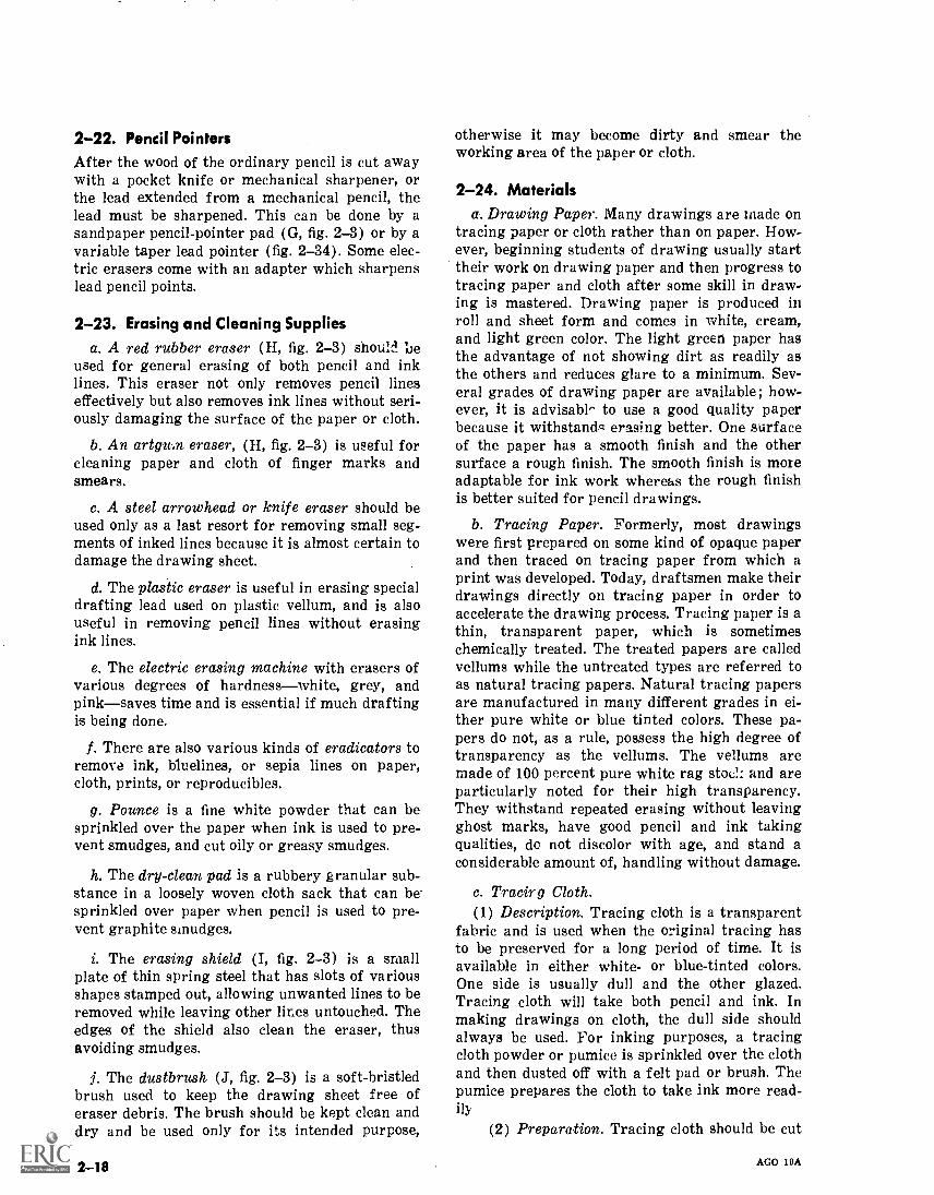
2-22. Pencil PointersAfter the wood of the ordinary pencil is cut awaywith a pocket knife or mechanical sharpener, orthe lead extended from a mechanical pencil, thelead must be sharpened. This can be done by asandpaper pencil-pointer pad (G, fig. 2-3) or by avariable taper lead pointer (fig. 2-34). Some elec-tric erasers come with an adapter which sharpenslead pencil points.
2-23. Erasing and Cleaning Suppliesa. A red rubber eraser (H, fig. 2-3) should ue
used for general erasing of both pencil and inklines. This eraser not only removes pencil lineseffectively but also removes ink lines without seri-ously damaging the surface of the paper or cloth.
b. An artgu,n eraser, (H, fig. 2-3) is useful forcleaning paper and cloth of finger marks andsmears.
c. A steel arrowhead or knife eraser should beused only as a last resort for removing small seg-ments of inked lines because it is almost certain todamage the drawing sheet.
d. The plastic eraser is useful in erasing specialdrafting lead used on plastic vellum, and is alsouseful in removing pencil lines without erasingink lines.
e. The electric erasing machine with erasers ofvarious degrees of hardnesswhite, grey, andpinksaves time and is essential if much draftingis being done.
f. There are also various kinds of eradicators toremove ink, bluelines, or sepia lines on paper,cloth, prints, or reproducibles.
g. Pounce is a fine white powder that can besprinkled over the paper when ink is used to pre-vent smudges, and cut oily or greasy smudges.
h. The dry-clean pad is a rubbery granular sub-stance in a loosely woven cloth sack that can be-sprinkled over paper when pencil is used to pre-vent graphite smudges.
i. The erasing shield (I, fig. 2-3) is a smallplate of thin spring steel that has slots of variousshapes stamped out, allowing unwanted lines to beremoved while leaving other lines untouched. Theedges of the shield also clean the eraser, thusavoiding smudges.
j. The dustbrush (J, fig. 2-3) is a soft-bristledbrush used to keep the drawing sheet free oferaser debris. The brush should be kept clean anddry and be used only for its intended purpose,
2-18
otherwise it may become dirty and smear theworking area of the paper or cloth.
2-24. Materialsa. Drawing Paper. Many drawings are made on
tracing paper or cloth rather than on paper. How-ever, beginning students of drawing usually starttheir work on drawing paper and then progress totracing paper and cloth after some skill in draw-ing is mastered. Drawing paper is produced inroll and sheet form and comes in white, cream,and light green color. The light green paper hasthe advantage of not showing dirt as readily asthe others and reduces glare to a minimum. Sev-eral grades of drawing paper are available ; how-ever, it is advisabl^ to use a good quality paperbecause it withstand erasing better. One surfaceof the paper has a smooth finish and the othersurface a rough finish. The smooth finish is moreadaptable for ink work whereas the rough finishis better suited for pencil drawings.
b. Tracing Paper. Formerly, most drawingswere first prepared on some kind of opaque paperand then traced on tracing paper from which aprint was developed. Today, draftsmen make theirdrawings directly on tracing paper in order toaccelerate the drawing process. Tracing paper is athin, transparent paper, which is sometimeschemically treated. The treated papers are calledvellums while the untreated types are referred toas natural tracing papers. Natural tracing papersare manufactured in many different grades in ei-ther pure white or blue tinted colors. These pa-pers do not, as a rule, possess the high degree oftransparency as the vellums. The vellums aremade of 100 percent pure white rag stoc!: and areparticularly noted for their high transparency.They withstand repeated erasing without leavingghost marks, have good pencil and ink takingqualities, do not discolor with age, and stand aconsiderable amount of, handling without damage.
c. Tracing Cloth.(1) Description. Tracing cloth is a transparent
fabric and is used when the original tracing hasto be preserved for a long period of time. It isavailable in either white- or blue-tinted colors.One side is usually dull and the other glazed.Tracing cloth will take both pencil and ink. Inmaking drawings on cloth, the dull side shouldalways be used. For inking purposes, a tracingcloth powder or pumice is sprinkled over the clothand then dusted off with a felt pad or brush. Thepumice prepares the cloth to take ink more read-ily
(2) Preparation. Tracing cloth should be cut
AGO 19A
several inches larger than the required finish size.For large drawings, allow the tracir,g cloth to lieflat for a short time before tacking it down. Occa-sional traces of oil that appear on tracing clothprevent a smooth flow of ink; dusting the sheetwith pounce or powdered chalk after it has beentacked down and wiping it with clean, dry clothwill remove any traces of oil.
(3) Erasing. Erasing inked lines must bedone with care if re-inking is contemplated; apencil eraser can be used in conjunction with anerasing shield to avoid wrinkling the paper. Atriangle slipped underneath the tracing cloth atthe point of erasure also minimizes wrinkling.The erased spot should be finished smooth with athumbnail or triangle edge after erasing. A clothdipped in carbon tetrachloride or benzine can beused to remove graphite smudges and pencil linesfrom tracing cloth. Never use a knife eraser on aline that must be re-inked because it will invaria-bly damage the surfaa enough to permit ink toseep through. Use a draftsman's dustbrush to re-move eraser debris.
(4) Moisture. Certain types of tracing clothare sensitive to moisture and atmosphericchanges. Do not allow moist hands and arms tocome in contact with tracing cloth. For large trac-ings, it is advisable to cut a shield from detailpaper to protect finished work. When the makingof a tracing is to extend over several days, it isrecommended that one view at a time be fullycompleted rather than working over the entirearea. The cloth is quite responsive to changes inthe moisture content of the air and will expand orshrink a great deal from one day to the next.
d. Plastic. Plastic paper, such as Mylar, Helios,Polyester, and so on, is transparent, more durable,and can be easily erased without leaving a "ghost"or damaging the working surface.
e. Cross Section Paper. Cross section paper isprinted in many different grid sizes; but it isusually printed in green or red squares with 100squares (10 X 10) or 400 squares (20 x 20) tothe square inch and is available in sheets or rolls.Cross section paper is used to plot statistical data,graphs, and road elevations taken transversely tothe centerline section of the road. It can also beused for sketching using the various squares as aguide.
f. Profile Paper. Profile paper is generally usedin road work. The lower half of the paper is nor-mally printed in orange squares, of 4 divisionshorizontally by 20 divisions vertically to thesquare inch. The upper half of the sheet is blankand is used for drawing a plan view as of a road
AGO 19A
seen from the air. The portion printed with or-aZge squares is used to plot the elevation of theroad along its centerline. The most common sizesare 23 by 36 inches; special sizes and profile paperin rolls are obtainable on special order in quan-tity. For further details refer to TM 5-581B.
g. Poster Board. Poster board is used by themilitary draftsman mainly for charts and graphs.Made with sturdy 3-ply construction, the smooth,write surface of these boards accepts ink easily.Available with printed border and titles or plain,the boards may be rolled without damage to boardor surface.
2-25. Paper Fastenersa. A drawing sheet can be fastened to the draw-
ing board with drafting, masking, or cellophanetape. Though these tapes do not make holes likethumbtacks or staplers, they may roll up underthe T-square or damage or leave sticky gum onthe paper or drafting board. Thumbtacks prefera-bly with thin flat heads, or wire staples insertedwith a stapling machine can be used but theydamage the working surface of the drawing boardunless it is protected with a plastic drafting boardcover that is self-sealing.
b. Since the T-square blade is more rigid nearthe head than toward the outer end, the papershould be placed close to the left edge of the boardwith its lower edge several inches from the bot-tom of the board, With the T-square against theleft edge of the board, square the top of thepaper ; hold it in this position, slipping the T-square down from the edge, and fasten each uppercorner. Then move the T-square down over thepaper to smooth out possible wrinkles, and fastenthe other two corners. When the sheet is larger,fasten drawing material in between corners asnecessary.
2-26. Special Equipmenta. Mechanical Lettering Sets.
(1) One type of mechanical lettering set con-sists of five component parts: a number of guidesor templates in which the lines of the letters areindented, a three-legged scriber, a number of ink-ing pens of varying sizes and a pen holder with aspecial penciling attachment for the scriber. Oneleg of the scriber holds the pen or pencil, and theother two legs terminate in tracer points. Onetracer point or tail pin moves in a long, straightgroove on the template. When this latter point ismoved around the contour of a letter, the entirescriber hinges on the tail pin in the groove and
2-19
the pen or pencil traces the letter on the drawingpaper. Refer to paragraphs 4-13 through 4-15
and figure 4-11 for a complete description and useof this set.
(2) Another type of lettering set contains avertical penholder for various penpoints and anumber of templates. Each template contains anumber of differently shaped perforations fromwhich letters in one size and style can be sten-ciled.
(3) The Varigraph is a more elaborate devicefor making a wide variety of either single-strokeletters or "built-up" letters. The Letterguide scrib-er is a much simpler instrument, which alsomakes a large variety of styles and sizes of letterswhen used with various templates available. Theyboth operate with a guide pin moving in thegrooved letters of the template, while the pen,which is mounted on an adjustable arm, makesthe letters in outline. The letters can be filled inblack, zip-a-toned, shaded, left blank, or reversed,that is, white letters with a black background.
b. Scribing Instruments. The standard militarymethod of making color separations for map re-production is the use of scribing instruments on
2-20
coated plastic sheets. The principal scribing in-struments are called gravers, which hold scribingneedles or blades. There are several types of grav-ers and accessories. For detailed information oftheir use, refer to TM 5-240.
c. Slide Rule. A slide rule (T, fig. 2-3) is aportable calculating device based on the principleof logarithmic addition and subtraction. Computa-tions are an important part of engineering draw-ing and a draftsman who is proficient in the useof a slide rule finds it an essential aid in rapidcalculations.
d. Other Miscellaneous Items. Certain otheritems may or may not be available to the drafts-man through local purchase or supply, but may beused by the draftsman if available. They include,but are not limited to: pantographs, polar planim-eter, scale guards, lettering triangle, parallelrules, hatching pens, Zip-a-tone, Prestype, horncenters, tri-tractor map measures, paper cutters,tack lifters, staple removers, oilstones, drafts-man's pencil sharpeners, horizontal map files, ver-tical plan hold files, stack roll files, mailing tubes,headliner, and so forth.
AGO 19A
CHAPTER 3
LINE WEIGHTS, CONVENTIONS AND FORMATS
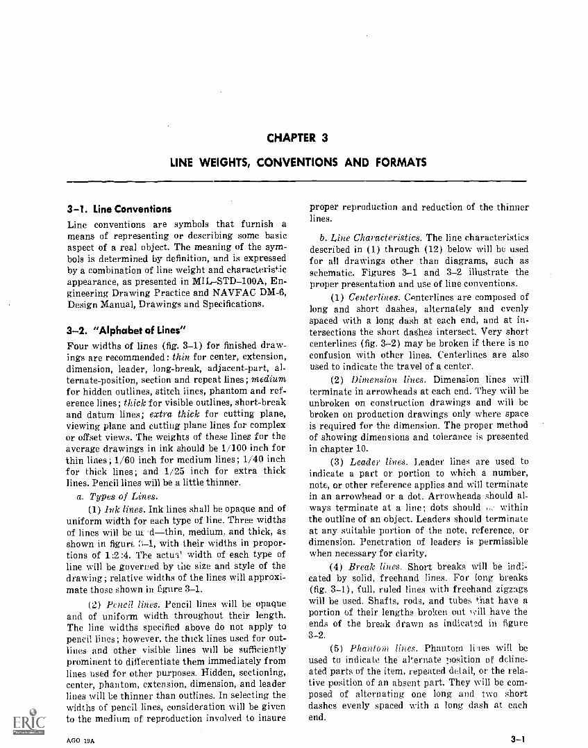
3-1. Line ConventionsLine conventions are symbols that furnish ameans of representing or describing some basicaspect of a real object. The meaning of the sym-bols is determined by definition, and is expressedby a combination of line weight and characteris'icappearance, as presented in MILSTD-100A, En-gineering Drawing Practice and NAVFAC DM-6,Design Manual, Drawings and Specifications.
3-2. "Alphabet of Lines"Four widths of lines (fig. 3-1) for finished draw-ings are recommended: thin for center, extension,dimension, leader, long-break, adjacent-part, al-ternate-position, section and repeat lines ; medium,for hidden outlines, stitch lines, phantom and ref-erence lines; thick for visible outlines, short-breakand datum lines; extra thick for cutting plane,viewing plane and cutting plane lines for complexor offset views. The weights of these lines for theaverage drawings in ink should be 1/100 inch forthin lines ; 1/60 inch for medium lines ; 1/40 inchfor thick lines ; and 1/25 inch for extra thicklines. Pencil lines will be a little thinner.
a. Types of Lines.(1) Ink lines. Ink lines shall be opaque and of
uniform width for each type of line. Three widthsof lines will be W. ,'dthin, medium, and thick, asshown in figure 1, with their widths in propor-tions of 1:2:4. The actual width of each type ofline will be governed by the size and style of thedrawing ; relative widths of the lines will approxi-mate those shown in figure 3-1.
(2) Pencil lines. Pencil lines will be opaqueand of uniform width throughout their length.The line widths specified above do not apply topencil lines; however, the thick lines used for out-lines and other visible lines will be sufficientlyprominent to differentiate them immediately fromlines used for other purposes. Hidden, sectioning,center, phantom, extension, dimension, and leaderlines will be thinner than outlines. In selecting thewidths of pencil lines, consideration will be givento the medium of reproduction involved to insure
AGO 19A
proper reproduction and reduction of the thinnerlines.
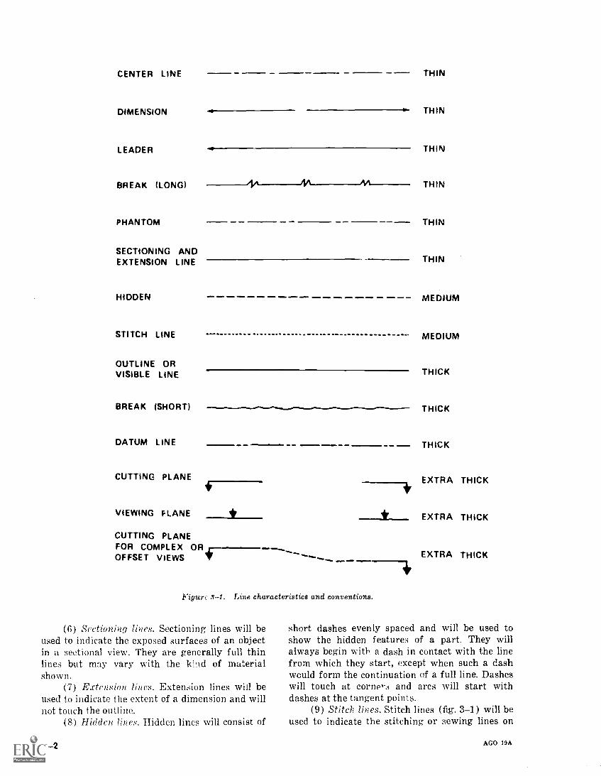
b. Line Characteristics. The line characteristicsdescribed in (1) through (12) below will be usedfor all drawings other than diagrams, such asschematic. Figures 3-1 and 3-2 illustrate theproper presentation and use of line conventions.
(1) Centerlines. Centerlines are composed oflong and short dashes, alternately and evenlyspaced with a long dash at each end, and at in-tersections the short dashes intersect. Very shortcenterlines (fig. 3-2) may be broken if there is noconfusion with other lines. Centerlines are alsoused to indicate the travel of a center.
(2) Dimension lines. Dimension lines willterminate in arrowheads at each end. They will beunbroken on construction drawings and will bebroken on production drawings only where spaceis required for the dimension. The proper methodof showing dimensions and tolerance is presentedin chapter 10.
(3) Leader lines. Leader lines are used toindicate a part or portion to which a number,note, or other reference applies and will terminatein an arrowhead or a dot. Arrowheads should al-ways terminate at a line ; dots should withinthe outline of an object. Leaders should terminateat any suitable portion of the note, reference, ordimension. Penetration of leaders is permissiblewhen necessary for clarity.
(4) Break lines. Short breaks will be indi-cated by solid, freehand lines. For long breaks(fig. 3-1), full, ruled lines with freehand zigzagswill be used. Shafts, rods, and tubes that have aportion of their lengths broken out will have theends of the break drawn as indicated in figure3-2.
(5) Phantom lilies. Phantom liges will beused to indicate the alternate position of deline-ated parts of the item, repeated detail, or the rela-tive position of an absent part. They will be com-posed of alternating one long and two shortdashes evenly spaced with a long dash at eachend.
3-1
CENTER LINE
DIMENSION
LEADER
BREAK (LONG)
PHANTOM
SECTIONING ANDEXTENSION LINE
HIDDEN
STITCH LINE
OUTLINE ORVISIBLE LINE
BREAK (SHORT)
DATUM LINE
CUTTING PLANE
VIEWING PLANE
CUTTING PLANEFOR COMPLEX OROFFSET VIEWS
THIN
THIN
THIN
THIN
THIN
THIN
maaw MM.
Figure 3-1. Line characteristics and conventions.
(6) Sectioning lines. Sectioning lines will beused to indicate the exposed surfaces of an objectin a sectional view. They are generally full thinlines but may vary with the kind of materialshown.
(7) Extension lines. Extension lines will beused to indicate the extent of a dimension and willnot touch the outline.
(8) Hidden lines. Hidden lines will consist of
3-2
MEDIUM
MEDIUM
THICK
THICK
THICK
EXTRA THICK
EXTRA THICK
EXTRA THICK
short dashes evenly spaced and will be used toshow the hidden features of a part. They willalways begin with a dash in contact with the linefrom which they start, except when such a dashwould form the continuation of a full line. Dasheswill touch at corne,..i and arcs will start withdashes at the tangent points.
(9) Stitch lines. Stitch lines (fig. 3-1) will beused to indicate the stitching or sewing lines on
AGO 19A
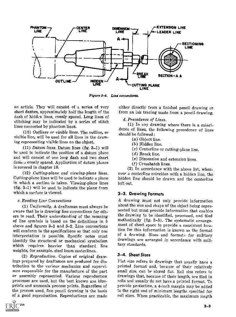
UNE CLINE RDIMENSIONa
LINE
A
LINELEADER LINE
SECTIONINGLINE
OUTLINE HIDDENUNE
Like SECTION-A A
CUTTING PLANELINE
Figure 3-2. Lino convention..
an article. They will consist of a series of veryshort dashes, approximately half the length of thedash of hiddon lines, evenly spaced. Long lines ofstitching may be indicated by a series of stitchlines connected by phantom lines.
(10) Outlines or visible lines. The outline, orvisible line, will be used for all lines in the draw-ing representing visible lines on the object.
(11) Datum lines. Datum lines (fig. 3-1) willbe used to indicate the position of a datum planeand will consist of one long dash and two shortdasii.,3 evenly spaced. Application of datum planesis covered in chapter 10.
(12) Cutting-plane and viewing-plane lines.Cutting-plane lines will be used to indicate a planein which a section is taken. Viewing-plane lines(fig. 3-1) will be used to indicate the plane fromwhich a surface is viewed.
c. Reading Lino Conventions(1) Uniformity. A draftsman must always be
aware that he is drawing line conventions for oth-ers to read. Their understanding of the meaningof line symbols is based on the definitions in babove and figures 3-1 and 3-2. Line conventionswill conform to the specifications so that only oneinterpretation is possible. Specific notes mustidentify the structural or mechanical symbolismwhich requires heavier than standard lineweights, for example, steel beam centerlines.
(2) Reproduction. Copies of original draw-ings prepared by draftsmen are produced for dis-tribution to the various mechanics and supervi-sors responsible for the manufacture of the partor assembly represented. Various reproductionprocesses are used, but the best known are blue-prints and ammonia process prints. Regardless ofthe process used, fine pencil drawing is the basisof a good reproduction. Reproductions are made
AGO 19A
either directly from a finished pencil drawing orfrom an ink tracing made from a pencil drawing.
d. Precedence of Lines.(1) In any drawing where there is a coinci-
dence of lines, the following precedence of linesshould be followed :
(a) Object line.(b) Hidden line.(c) Centerline or cutting-plane line.(d) Break line.(e) Dimension and extension lines.(1) Crosshatch lines.
(2) In accordance with the above list, when-ever a centerline coincides with a hidden line, thehidden line should be drawn and the centerlineleft out.
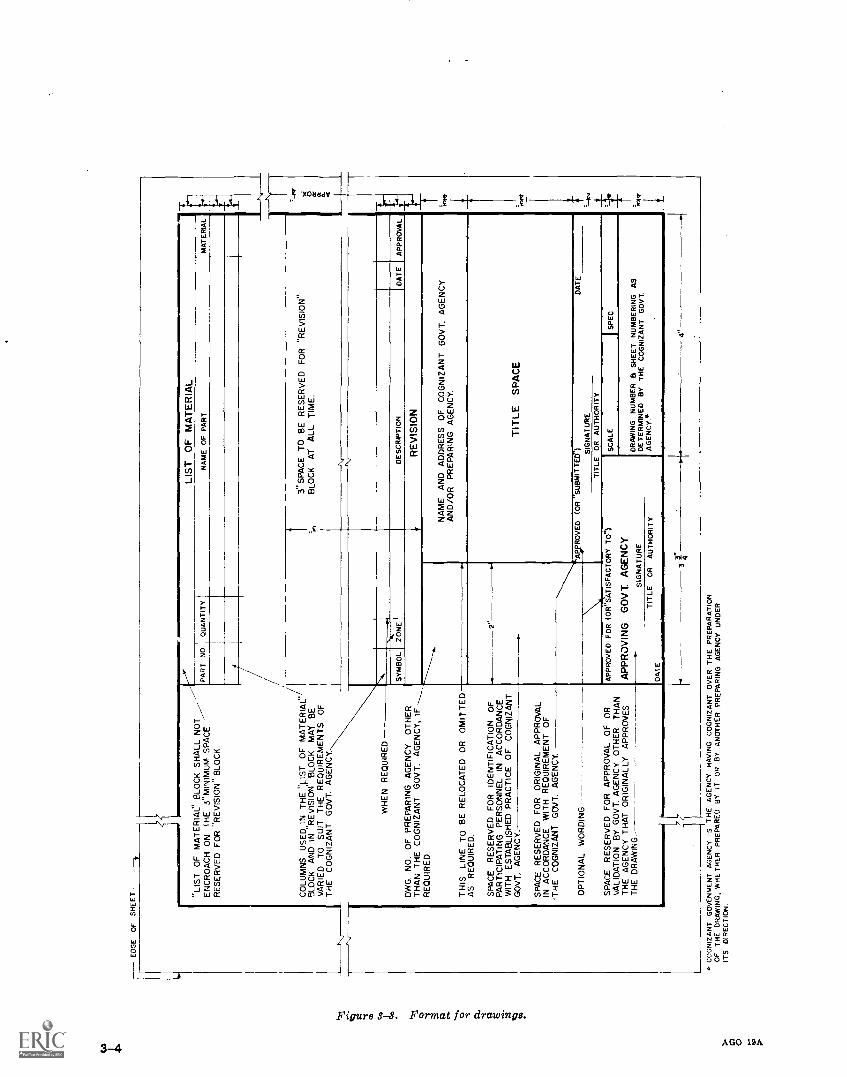
3-3. Drawing FormatsA drawing must not only provide informationabout the size and shape of the object being repre-sented but must provide information that enablesthe drawing to be identified, processed, and filedmethodically (fig. 3-3). The systematic arrange-ment of sheet space to provide a consistent loca-tion for this information is known as the formatof a drawing. Sizes and formats for militarydrawings are arranged in accordance with mili-tary standards.
3-4. Sheet Sizes
Flat size refers to drawings that usually have aprinted format and, because of their relativelysmall size, can be stored flat. Roll size refers todrawings that, because of their length, are filed inrolls and usually do not have a printed format. Toprovide protection, a 4-inch margin may be addedto the right end of minimum lengths specified forroll sizes. When practicable, the maximum length
3-3
ED
GE
OF
SH
EE
T "LIS
T O
F M
AT
ER
IAC
BLO
CK
SH
ALL
NO
TP
AR
T N
OE
NC
RO
AC
H O
N (
HE
3"
MIN
IMU
M S
PA
CE
RE
SE
RV
ED
FO
R R
EV
ISIO
N B
LOC
K
CO
LUM
NS
US
ED
IN T
HE
flpS
T O
F M
AT
ER
IAL:
.B
LOC
K A
ND
IN R
EV
ISIO
N B
LOC
K M
AY
BE
VA
RIE
D T
O S
UIT
TH
E R
EQ
UIR
EM
EN
TS
OF
TH
E C
OG
NIZ
AN
T G
OV
T. A
GE
NC
Y..
WH
EN
RE
QU
IRE
D
LIS
T O
F M
AT
ER
IAL
QU
AN
TIT
YN
AM
E O
F P
AR
T
3" S
PA
CE
TO
BE
RE
SE
RV
ED
FO
R "
RE
VIS
ION
'B
LOC
K A
T A
LL T
IME
.
DW
G. N
O. O
F P
RE
PA
RIN
G A
GE
NC
Y O
TH
ER
TH
AN
TH
E C
OG
NIZ
AN
T G
OV
T. A
GE
NC
Y, I
F -
RE
QU
IRE
D.
TH
IS L
INE
TO
BE
RE
LOC
AT
ED
OR
OM
ITT
ED
AS
RE
QU
IRE
D.
SP
AC
E R
ES
ER
VE
D F
OR
IDE
NT
IFIC
AT
ION
OF
PA
RT
ICIP
AT
ING
PE
RS
ON
NE
L IN
AC
CO
RD
AN
CE
WIT
H E
ST
AB
LIS
HE
D P
RA
CT
ICE
OF
CO
GN
IZA
NT
GO
VT
. AG
EN
CY
.
SP
AC
E R
ES
ER
VE
D F
OR
OR
IGIN
AL
AP
PR
OV
AL
IN A
CC
OR
DA
NC
E W
ITH
RE
QU
IRE
ME
NT
OF
TH
E C
OG
NIZ
AN
T G
CM
T. A
GE
NC
Y.
OP
TIO
NA
L W
OR
DIN
G
SY
MB
OL
ZO
NE
LI
DE
SC
RIP
TIO
ND
AT
EA
PP
RO
VA
L
RE
VIS
ION
NA
ME
AN
D A
DD
RE
SS
OF
CO
GN
IZA
NT
GO
VT
. AG
EN
CY
AN
D/O
R P
RE
PA
RIN
G A
GE
NC
Y.
SP
AC
E R
ES
ER
VE
D F
OR
AP
PR
OV
AL
OF
OR
VA
LID
AT
ION
BY
GO
VT
. AG
EN
CY
OT
HE
R T
HA
NT
HE
AG
EN
CY
TH
AT
OR
IGIN
ALL
Y A
PP
RO
VE
ST
HE
DR
AW
ING
.
TIT
LE S
PA
CE
AV
RO
VE
D (
OR
''S
UB
MIT
TE
Cr) SIG
NA
TU
RE
TIT
LE O
R A
UT
HO
RIT
Y
DA
TE
AP
PR
OV
ED
FO
R (
OR
"SA
TIS
FA
CT
OR
Y T
o
AP
PR
OV
ING
GO
VT
. AG
EN
CY
SIG
NA
TU
RE
TIT
LEO
R A
UT
HO
RIT
YD
AT
E
SC
ALE
SP
EC
DR
AW
ING
NU
MB
ER
a S
HE
ET
NU
MB
ER
ING
AS
DE
TE
RM
INE
D B
Y T
HE
CO
GN
IZA
NT
GO
VT
.A
GE
NC
Y.
I
34
CO
GN
IZA
NT
GO
VE
NM
EN
T A
GE
NC
Y IS
TH
E A
GE
NC
Y H
AV
ING
CO
GN
IZA
NT
OV
ER
TH
E P
RE
PA
RA
TIO
NO
F T
HE
DR
AW
ING
, WH
ET
HE
R P
RE
PA
RE
D B
Y IT
OR
BY
AN
OT
HE
R P
RE
PA
RIN
G A
GE
NC
Y U
ND
ER
ITS
DIR
EC
TIO
N.
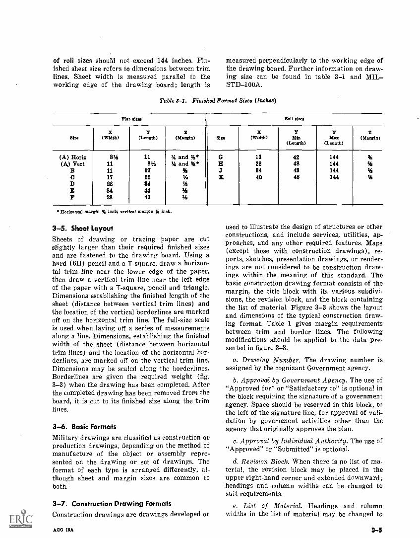
of roll sizes should not exceed 144 inches. Fin-ished sheet size refers to dimensions between trimlines. Sheet width is measured parallel to theworking edge of the drawing board; length is
measured perpendicularly to the working edge ofthe drawing board. Further information on draw-ing size can be found in table 3-1 and MILSTD-100A.
Table S-1. Finished Format Sizes (Inches)
Flat sizes Roll sizes
SizeX
(Width)Y
(Length)z
(Margin) Sizex
(Width)Y
Min(Length)
YMax
(Length)
z(Margin)
(A) Horiz(A) Vert
BCDEF
83111117228428
1183
1722844440
34 and %*1,4 and %*
%%%1/4
%
GHaIE
11288440
42484848
144144144144
%%%%
Horizontal margin % inch; vertical margin % inch.
3-5. Sheet LayoutSheets of drawing or tracing paper are cutslightly larger than their required finished sizesand are fastened to the drawing board. Using ahard (6H) pencil and a T-square, draw a horizon-tal trim line near the lower edge of the paper,then draw a vertical trim line near the left edgeof the paper with a T-square, pencil and triangle.Dimensions establishing the finished length of thesheet (distance between vertical trim lines) andthe location of the vertical borderlines are markedoff on the horizontal trim line. The full-size scaleis used when laying off a series of measurementsalong a line. Dimensions, establishing the finishedwidth of the sheet (distance between horizontaltrim lines) and the location of the horizontal bor-derlines, are marked off on the vertical trim line.Dimensions may be scaled along the borderlines.Borderlines are given the required weight (fig.3-3) when the drawing has been completed. Afterthe completed drawing has been removed from theboard, it is cut to its finished size along the trimlines.
3-6. Bask FormatsMilitary drawings are classified as construction orproduction drawings, depending on the method ofmanufacture of the object or assembly repre-sented on the drawing or set of drawings. Theformat of each type is arranged differently, al-though sheet and margin sizes are common toboth.
3-7. Construction Drawing FormatsConstruction drawings are drawings developed or
AGO 19A
used to illustrate the design of structures or otherconstructions, and include services, utilities, ap-proaches, and any other required features. Maps(except those with construction drawings), re-ports, sketches, presentation drawings, or render-ings are not considered to be construction draw-ings within the meaning of this standard. Thebasic construction drawing format consists of themargin, the title block with its various subdivi-sions, the revision block, and the block containingthe list of material. Figure 3-3 shows the layoutand dimensions of the typical construction draw-ing format. Table 1 gives margin requirementsbetween trim and border lines. The followingmodifications should be applied to the data pre-sented in figure 3-3.
a. Drawing Number. The drawing number isassigned by the cognizant Government agency.
b. Approvai! by Government Agency. The use of"Approved for" or "Satisfactory to" is optional inthe block requiring the signature of a governmentagency. Space should be reserved in this block, tothe left of the signature line, for approval of vali-dation by government activities other than theagency that originally approves the plan.
c. Approval by Individual Authority. The use of"Approved" or "Submitted" is optional.
d. Revision Block. When there is no list of ma-terial, the revision block may be placed in theupper right-hand corner and extended downward ;headings and column widths can be changed tosuit requirements.
e. List of Material. Headings and columnwidths in the list of material may be changed to
3-3
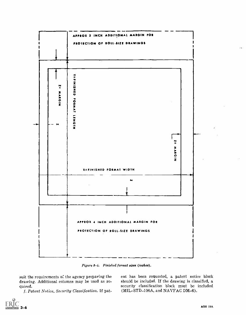
1
.11 4.11
APPROX 2 INCH ADDITIONAL MARGIN POI
PROTECTION Of ROLL.SIZE DRAWINGS
HA
H
it31.HP
0z
HNoiti;ZnoI,No
0
31.-4
r-noZ-- r4 0-.1
30i
X=FINISHED FORMAT WIDTH
N
APPROX 4 INCH ADDITIONAL MARGIN FOR
PROTECTION OF ROLL-SIZE DRAWINGS
Figure 3-4. Finished format sizes (inches).
suit the requirements of the agency preparing thedrawing. Additional columns may be used as re-quired.
f. Patent Notice, Security Classification. If pat-
3-6
ent has been requested, a patent notice blockshould be included. If the drawing is classified, asecurity classification block must be included(MILSTD-100A, and NAVFAC DM-6).
AGO 19A
3-8. Production Drawing FormatsProduction drawings represent those types ofequipment or articles that are produced in quan-tity, or that are of such design as to permit suchproduction. The basic format consists of the mar-gin (fig. 3-4), title block, and revision block.
a. Title Block. The title block is located in thelower right-hand corner of the drawing. It con-tains the number that identified the drawing ; thedraw' ig nun,ber (located in a block in the lowerright-hand corner of the titre block) ; and certaininformation conmon to all drawings, includingthe name and address of the government agencypreparing the Drawing, the title of the drawingscale, drafting record, authentication, and date.
b. Line Weights and Lettering. All lettering andnumbering that ordinarily would be printed ondrawing forms to indicate items, such as zoning,column headings, and space identification, may beof any appropriate size. Line weights and allother lettering are the same as specified for con-struction drawing formats.
c. Additional Specifications. For further specifi-cations concerning size, location, and use of theblocks described above, as well as data on supple-mentary blocks, security classification, and patentnotices, refer to MILSTD-100A.
3-9. Order of InkingLines are inked in a definite order to save time
AGO 19A
that would otherwise be wasted in waiting forinked lines to dry, and to produce lines of thesame width from the same adjusting screw set-ting. The natural progression for the right-handedperson for drawing horizontal lines is from top tobottom ; vertical lines normally are drawn in se-quence from the left to the right-hand side of thesheet.
a. Centerlines. Ink all centerlines first ; beginwith centerlines for full circles.
b. Points of Tangency. Be sure all tangentpoints are marked in pencil directly on tracing.
c. Thick Lines. Ink all arcs and circles, irregu-lar curves ; then all horizontal lines from the topdown, vertical lines beginning at the left, and theninclined lines.
d. Medium Lines. Ink all hidden and stitch linesin the order described in c above.
e. Thin Lines. Ink all dimensions, extension,leader, phantom, and sectioning lines next, andinclined lines last. When drawing sectioning lines,
."do not attempt to trace them; place a blank sheetof paper between the pencil drawing and the trac-ing cloth and draw sectioning lines by eye.
f. Freehand Lettering. Ink all arrowheads, di-mension figures, specific notes, and general notesincluding the list of materials.
g. Border and Title Block. Ink borderlines, andletter the title block.
3-7
CHAPTER 4
LETTERING
Section I. LETTERING REQUIREMENTS
4-1. Legible InformationThe shape and description of a part, machine, orstructure that is presented graphically by the var-ious views in a drawing will be supplemented byadditional information that is freehand or me-chanically lettered. Numerical dimensions, noteson material and finish, and a descriptive titleshould all be lettered in a style that is legible,uniform, and capable of rapid execution. As faras the appearance of a drawing is concerned, thelettering is the most important part. The useful-ness of a drawing can be destroyed by letteringdone haphazardly or carelessly, because illegiblefigures are apt to cause mistakes in the work.Illegible information may be interpreted by thecontractor to produce a cheaper and inferiorproduct or structure than required by the con-tract, or cause unnecessary expense due to a claimmade against the US Government by the contrac-tor.
4-2. StyleLettering style will be single-stroke upper-case,commercial Gothic, except when typewritten char-acters are used. Vertical lettering or inclined let-tering may be used, but only one type should ap-pear for a single drawing or set of drawings.Lower-case letters may be used on constructiondrawings, except for titles. 'Typewritten charac-ters may be uppercase or lowercase. The expres-sion single-stroke means that the width of linescomposing the letters is the same as the width ofa stroke of the pen or pencil used for lettering; itdoes not mean that each letter is executed with asingle, continuous movement of the pen or pencil.Uppercase refers to capital letters.
4-3. ProportionsThe ratio of letter width to letter height varieswith individual letters. This chapter presentsstandard proportions that take into considerationthe characteristics of individual letters. Lettersusing these proportions are called normal letters.
AGO 19A
When letter width is decreased in relation to let-ter height to conserve space, the letters are said tobe compressed letters. When letter width is in-creased in relation to letter height, the letters areknown as extended letters.
4-4. StabilityIf the areas of the upper and lower portions ofcertain letters and numerals are made equal, anoptical illusion is created which causes them toseem top-heavy. To correct this and give the im-pression of stability, the letters B, E, F, H, K, S,X, and Z, and the numbers 2, 3, 5, and 8 must bedrawn smaller at the top than at the bottom.
4-5. UniformityLettering in a drawing will present a uniformappearance. Height, inclination, alinement, lineweight, and spacing are the principal considera-tions. Uniform height, alinement, and inclinationare achieved through the use of guidelines; uni-formity in line weight depends on skillful use ofthe pencil or lettering pen. Uniform spacing ofletters in words and of words in sentences is per-formed by eye; good judgment results from prac-tice.
4-6. GuidelinesGuidelines are horizontal, vertical, and/or in-clines. They are always used in executing free-hand lettering. Horizontal guidelines determinehorizontal alinement, letter height, and the spac-ing between lines of lettering. Two horizontalguidelines are used for uppercase letters; theupper line is called the cap line, and the lower lineis called the baseline. The distance between caplines and baselines establishes the height of up-percase letters. Guide lines for lowercase lettersare constructed in proportion to uppercase sizes.Four horizontal guidelines are used, cap lines andbaselines being the same. The two f.clditional linesare called the waistlines and droplines. Verticaland inclined guidelines serve to keep the vertical-
4-1
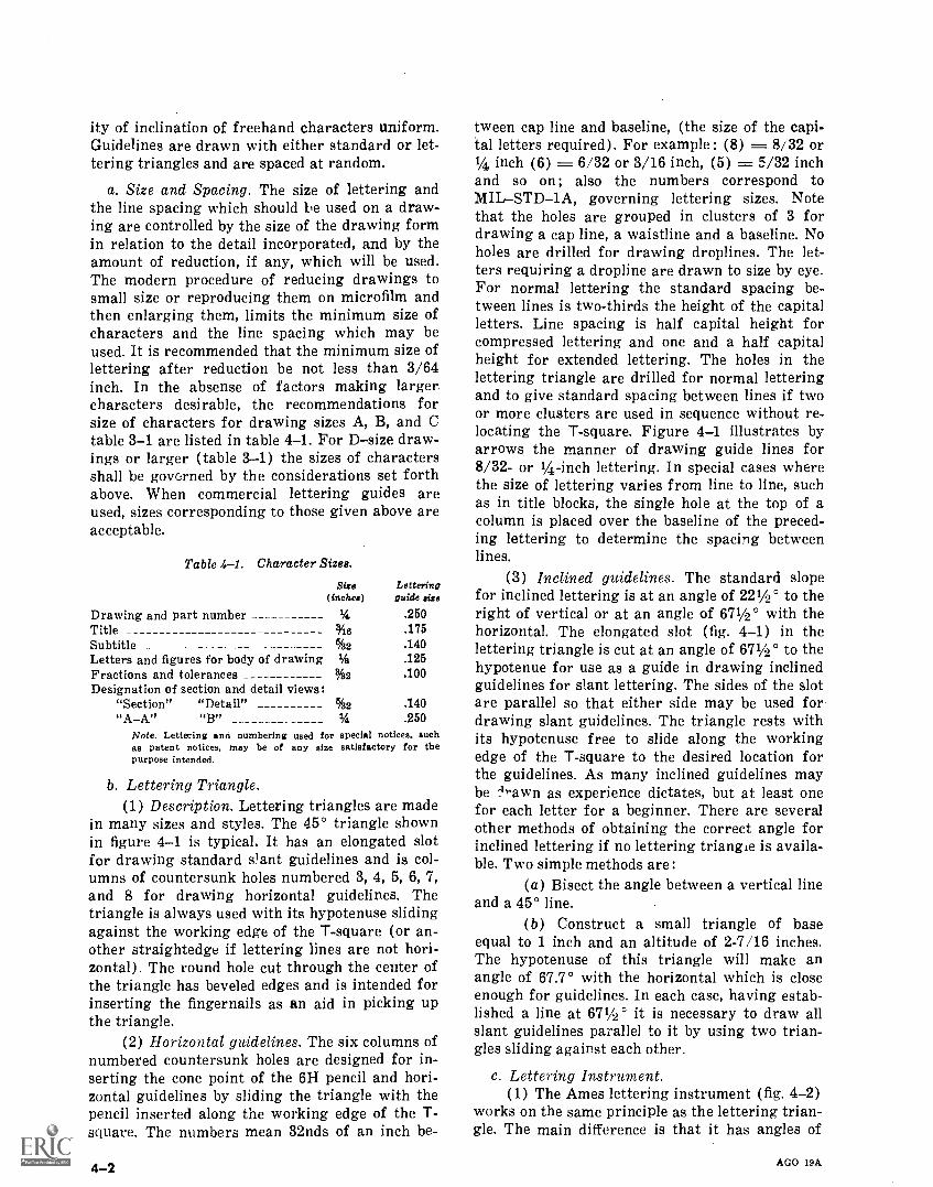
ity of inclination of freehand characters uniform.Guidelines are drawn with either standard or let-tering triangles and are spaced at random.
a. Size and Spacing. The size of lettering andthe line spacing which should be used on a draw-ing are controlled by the size of the drawing formin relation to the detail incorporated, and by theamount of reduction, if any, which will be used.The modern procedure of reducing drawings tosmall size or reproducing them on microfilm andthen enlarging them, limits the minimum size ofcharacters and the line spacing which may beused. It is recommended that the minimum size oflettering after reduction be not less than 3/64inch. In the absense of factors making larger.characters desirable, the recommendations forsize of characters for drawing sizes A, B, and Ctable 3-1 are listed in table 4-1. For Dsize draw-ings or larger (table 3-1) the sizes of charactersshall be govorned by the considerations set forthabove. When commercial lettering guides areused, sizes corresponding to those given above areacceptable.
Table 4-1. Character Sizes.
Size Letteringguide size(inches)
Drawing and part number I/4 .250Title 44e .175Subtitle 6/s2 .140Letters and figures for body of drawing M3 .125Fractions and tolerances %2 .100Designation of section and detail views:
"Section" "Detail" %2 .140"AA" ,,B,,
1/4, .250Note. Lettering ana numbering used for special notices, suchas patent notices, may be of any size satisfactory for thePurpose intended.
b. Lettering Triangle.(1) Description. Lettering triangles are made
in many sizes and styles. The 45° triangle shownin figure 4-1 is typical. It has an elongated slotfor drawing standard &ant guidelines and is col-umns of countersunk holes numbered 3, 4, 5, 6, 7,and 8 for drawing horizontal guidelines. Thetriangle is always used with its hypotenuse slidingagainst the working edge of the T-square (or an-other straightedge if lettering lines are not hori-zontal). The round hole cut through the center ofthe triangle has beveled edges and is intended forinserting the fingernails as an aid in picking upthe triangle.
(2) Horizontal guidelines. The six columns ofnumbered countersunk holes are designed for in-serting the cone point of the 611 pencil and hori-zontal guidelines by sliding the triangle with thepencil inserted along the working edge of the T-square. The numbers mean 32nds of an inch be-
4-2
tween cap line and baseline, (the size of the capi-tal letters required). For example : (8) = 8/32 or1/4 inch (6) = 6/32 or 3/16 inch, (5) = 5/32 inchand so on; also the numbers correspond toMILSTD-1A, governing lettering sizes. Notethat the holes are grouped in clusters of 3 fordrawing a cap line, a waistline and a baseline. Noholes are drilled for drawing droplines. The let-ters requiring a dropline are drawn to size by eye.For normal lettering the standard spacing be-tween lines is two-thirds the height of the capitalletters. Line spacing is half capital height forcompressed lettering and one and a half capitalheight for extended lettering. The holes in thelettering triangle are drilled for normal letteringand to give standard spacing between lines if twoor more clusters are used in sequence without re-locating the T-square. Figure 4-1 illustrates byarrows the manner of drawing guide lines for8/32- or 1/4-inch lettering. In special cases wherethe size of lettering varies from line to line, suchas in title blocks, the single hole at the top of acolumn is placed over the baseline of the preced-ing lettering to determine the spacing betweenlines.
(3) Inclined guidelines. The standard slopefor inclined lettering is at an angle of 221/2 ° to theright of vertical or at an angle of 671/2° with thehorizontal. The elongated slot (fig. 4-1) in thelettering triangle is cut at an angle of 671/00 to thehypotenue for use as a guide in drawing inclinedguidelines for slant lettering. The sides of the slotare parallel so that either side may be used fordrawing slant guidelines. The triangle rests withits hypotenuse free to slide along the workingedge of the T-square to the desired location forthe guidelines. As many inclined guidelines maybe -4-awn as experience dictates, but at least onefor each letter for a beginner. There are severalother methods of obtaining the correct angle forinclined lettering if no lettering triangle is availa-ble. Two simple methods are:
(a) Bisect the angle between a vertical lineand a 45° line.
(b) Construct a small triangle of baseequal to 1 inch and an altitude of 2-7/16 inches.The hypotenuse of this triangle will make anangle of 67.7° with the horizontal which is closeenough for guidelines. In each case, having estab-lished a line at 671/2 ° it is necessary to draw allslant guidelines parallel to it by using two trian-gles sliding against each other.
c. Lettering Instrument.(1) The Ames lettering instrument (fig. 4-2)
works on the same principle as the lettering trian-gle. The main difference is that it has angles of
AGO I9A
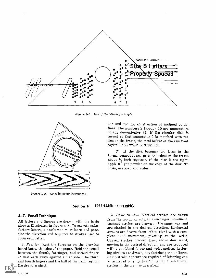
I ///
'Y MIIMILSOILVA.
0O
o
000 0°.000 00
000 000 00GO 0 GO
0 0 00 °00® 0 00 0
3 4 5
O
oe00 0
O 0000 0
O Ott00 0O 0o 0
A00 o0
O 0 0
RACE) LNF IIROVE
-67."wira MN IN 4-
!". AWN A L'AW"Ill
0000o
6 7 8
Figure 4-1. Use of the lettering triangle.
Figure 4-2. Ames lettering instrument.
68° and 75° for construction of inclined guide-lines. The numbers 2 through 10 are numeratorsof the denominator 32. If the circular disk isturned so that numerator 9 is matched with theline on the frame, the tc tal height of the resultantcapital letter would be 9/32 inch.
(2) If the disk becomes too loose in theframe, remove it ancl press the edges of the frameabout 1/4 inch togetner. If the disk is too tight,apply a light powder on the edge of the disk. Toclean, use soap and water.
Section li. FREEHAND LETTERING
4-7. Pencil TechniqueAll letters and figures are drawn with the basicstrokes illustrated in figure 4-3. To execute satis-factory letters, a draftsman must learn and prac-tice the direction and sequence of strokes used toform each letter.
a. Position. Rest the forearm on the drawingboard below the edge of the paper. Hold the pencilbetween the thumb, forefinger, and second fingerso that each rests against a flat side. The thirdand fourth fingers and the ball of the palm rest onthe drawing sheet.
AGO 19A
b. Basic Strokes. Vertical strokes are drawnfrom the top down with an even finger movement.Inclined strokes are drawn in the same way andare slanted in the desired direction. Horizontalstrokes are drawn from left to right with a com-plete hand movement, pivoting at the wrist.Curved strokes proceed from above downward,moving in the desired direction, and are producedwith a combined finger and wrist motion. Letter-ing strokes are drawn, not sketched ; the uniform,single-stroke appearance required of lettering canbe achieved only by practicing the fundamentalstrokes in the manner described.
4-3
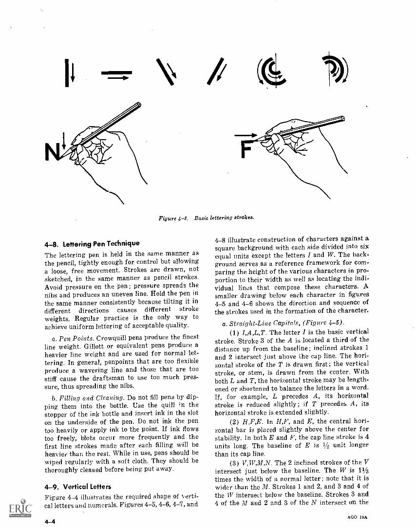
Figure 4-8. Basic lettering strokes.
4-8. Lettering Pen TechniqueThe lettering pen is held in the same manner asthe pencil, tightly enough for control but allowinga loose, free movement. Strokes are drawn, notsketched, in the same manner as pencil strokes.Avoid pressure on the pen ; pressure spreads thenibs and produces an uneven line. Hold the pen inthe same manner consistently because tilting it indifferent directions causes different strokeweights. Regular practice is the only way toachieve uniform lettering of acceptable quality.
a. Pen Points. Crowquill pens produce the finestline weight. Gillott or equivalent pens produce aheavier line weight and are used for normal let-tering. In general, penpoints that are too flexibleproduce a wavering line and those that are toostiff cause the draftsman to use too much pres-sure, thus spreading the nibs.
b. Filling and Cleaning. Do not fill pens by dip-ping them into the bottle. Use the quill ;n thestopper of the ink bottle and insert ink in the sloton the underside of the pen. Do not ink the pentoo heavily or apply ink to the point. If ink flowstoo freely, blots occur more frequently and thefirst line strokes made after each filling will beheavier than the rest. While in use, pens should bewiped regularly with a soft cloth. They should bethoroughly cleaned before being put away.
4-9. Vertical LettersFigure 4-4 illustrates the required shape of verti-cal letters and numerals. Figures 4-5, 4-6, 4-7, and
4-8 illustrate construction of characters against asquare background with each side divided into sixequal units except the letters I and W. The back-ground serves as a reference framework for com-paring the height of the various characters in pro-portion to their width as well as locating the indi-vidual lines that compose these characters. Asmaller drawing below each character in figures4-5 and 4-6 shows the direction and sequence ofthe strokes used in the formation of the character.
a. Straight-Line Capitals, (Figure 4-5).(1) I,A,L,T. The letter I is the basic vertical
stroke. Stroke 3 of the A is located a third of thedistance up from the baseline; inclined strokes 1and 2 intersect just above the cap line. The hori-zontal stroke of the T is drawn first ; the verticalstroke, or stem, is drawn from the center. Withboth L and T, the horizontal stroke may be length-ened or shortened to balance the letters in a word.If, for example, L precedes A, its horizontalstroke is reduced slightly ; if T precedes A, itshorizontal stroke is extended slightly.
(2) H,F,E. In H,F, and E, the central hori-zontal bar is placed slightly above the center forstability. In both E and F, the cap line stroke is 4units long. The baseline of E is 1/, unit longerthan its cap line.
(3) V,W,M,N. The 2 inclined strokes of the Vintersect just below the baseline. The W is 11/3
times the width of a normal letter ; note that it iswider than the M. Strokes 1 and 2, and 3 and 4 ofthe TV intersect below the baseline. Strokes 3 and4 of the M and 2 and 3 of the N intersect on the
AGO 19A
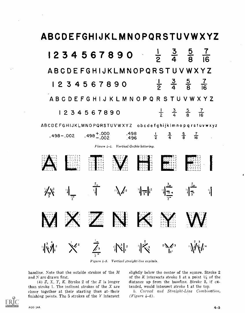
ABCDEFGHIJKLMNOPQRSTUVWXYZ
1 2 3 4 5 6 7 8 9 0 3 5 74 8 16
ABCDEFGHIJKLMNOPQRSTUVWXYZ
1 2 3 45 6 7 8 90 I 3 5 72 4 8 16
ABCDEFGHIJ KLMNOPQR STUVWXYZ
I 234 567890 I 3 5 72 4 8 16
ABCDEFGHIJKLMNOPQRSTUVWXYZ abcdefghijklmnopq rstuvwxyz
.498.002
r T 1-1 ' 1- . r 1: - ,- r - ,
L _ - :- 1,- 1.. ..1,
r r, ,_ ,_ _,,
. ,
7J - 1 -1- 1 J
-L L L
.498+.000.002.498.496 2
Fiaure 4-4. Vertical Gothic lettering.
2
r I4
L _
I- 1 tI_ I JJ
\12
r1J
3 5 74 8 16
,f4J/_L 14 J.
r T 1 1- t_ J
2
-
77
-
I
r 1- r
-;
_ ,- -
r
LJ-Lr "r1
LJ
Mi
/32
IN 'ilk:Figure 4-5. Vertical straight-line capitals.
baseline. Note that the outside strokes of the Mand N are drawn first.
(4) Z, Y, K. Stroke 2 of the Z is longerthan stroke 1. The inclined strokes of the X arecloser together at their starting than at theirfinishing points. The 3 strokes of the Y intersect
AGO 19A
2N43Ike
slightly below the center of the square. Stroke 2of the K intersects stroke 1 at a point IA3 of thedistance up from the baseline. Stroke 3, if ex-tended, would intersect stroke 1 at the top.
b. Curved and Straight -Line Combination,(Figure 4-6).
4-5
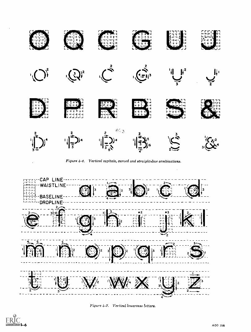
1--r I -T 1 -C. 71 r r r C. 1I f -4 111 -I 1-". t- 1+ - 4 L 1 e . . % -I L
e-
.4 1
-I - -I-I-I -1 /-1 4 -4 't -4 + ++ -4
4- -I -4L J L ., J i_ _LI -}
0 1 \ca3) C2
2
a Ii2
3 2
- 1
-I 1-1
4 -I 4- t-i -1 -1 -1J 1 J J -I
2 2 2
)4 I IF> I IF> 1195t 3 I 3 ) 6
-3.-5\3
'T "1 r 1 -11-14 -I L I- r 11-I L 1- s- 4
I- 1 I N 4 -II- 4 eta 1 4- 1
1 41.- 1
31
2
Figure 4-6. Vertical capitals, curved and straight -line combinations.
LINEWAISTLINE-----
BASELINE--"---1--DROPLINE
2
2
IJ
1--11 L -
4 5 3
L J
2 3
r 7 74 I-
3,1*.I
-r-I ti I-
-I3 \;
_I - _ _1-i -1-1
'El =
;_ ;
4 12 /
- - _
-2ri-It- r
. J
Figure 4-7. Vertical lowercase lettera.
AGO 19A
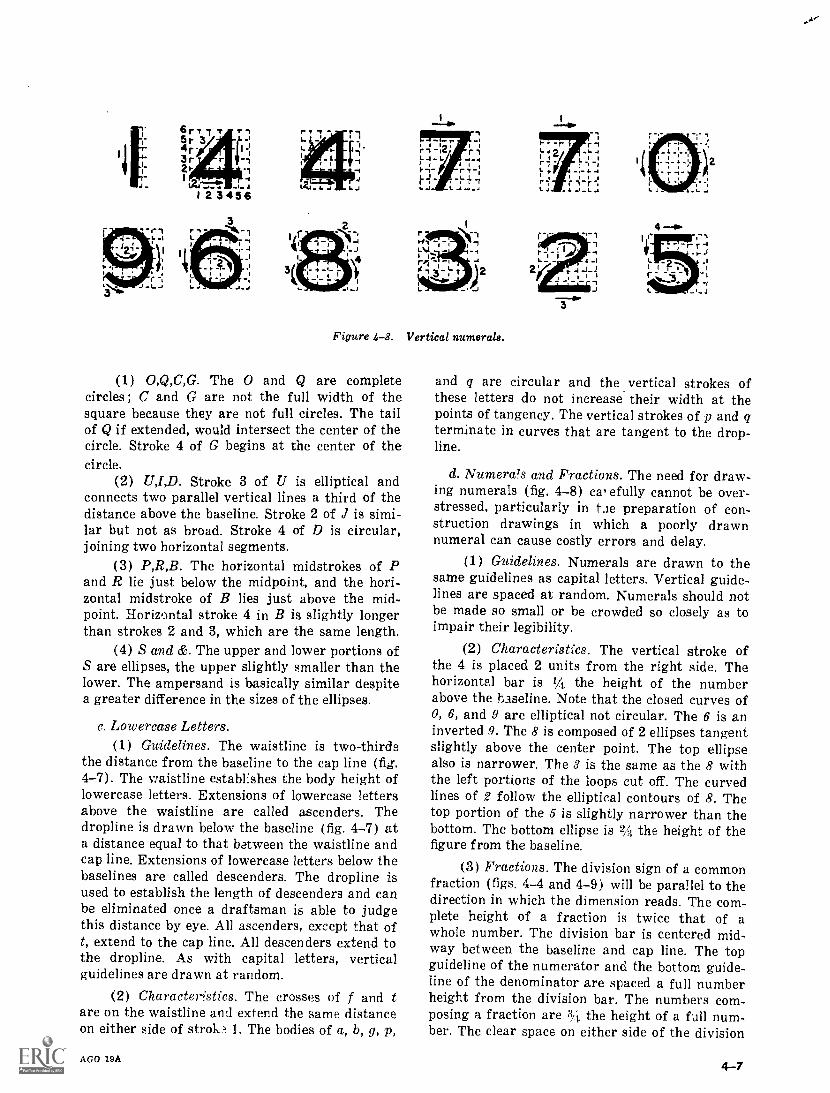
'
ti
L
4
-11.
I.-I
Figure 4-8. Vertical numerals.
( 1 ) 0,Q,C,G. The 0 and Q are completecircles; C and G are not the full width of thesquare because they are not full circles. The tailof Q if extended, would intersect the center of thecircle. Stroke 4 of G begins at the center of thecircle,
(2) UJ,D. Stroke 3 of U is elliptical andconnects two parallel vertical lines a third of thedistance above the baseline. Stroke 2 of J is simi-lar but not as broad. Stroke 4 of D is circular,joining two horizontal segments.
(3) P,R,B. The horizontal midstrokes of Pand R lie just below the midpoint, and the hori-zontal midstroke of B lies just above the mid-point. Horizontal stroke 4 in B is slightly longerthan strokes 2 and 3, which are the same length.
(4) S and &. The upper and lower portions ofS are ellipses, the upper slightly smaller than thelower. The ampersand is basically similar despitea greater difference in the sizes of the ellipses.
c. Lowercase Letters.(1) Guidelines. The waistline is two-thirds
the distance from the baseline to the cap line (fig.4-7). The waistline establishes the body height oflowercase letters. Extensions of lowercase lettersabove the waistline are called ascenders. Thedropline is drawn below the baseline (fig. 4-7) ata distance equal to that between the waistline andcap line. Extensions of lowercase letters below thebaselines are called descenders. The dropline isused to establish the length of descenders and canbe eliminated once a draftsman is able to judgethis distance by eye. All ascenders, except that oft, extend to the cap line. All descenders extend tothe dropline. As with capital letters, verticalguidelines are drawn at random.
(2) Characteristics. The crosses of f and tare on the waistline and extend the same distanceon either side of strok 1. The bodies of a, b, g, p,
AGO 113A
r3
and q are circular and the vertical strokes ofthese letters do not increase their width at thepoints of tangency. The vertical strokes of p and qterminate in curves that are tangent to the drop-line.
d. Numerals and Fractions. The need for draw-ing numerals (fig. 4-8) ca,efully cannot be over-stressed, particularly in tie preparation of con-struction drawings in which a poorly drawnnumeral can cause costly errors and delay,
( 1 ) Guidelines. Numerals are drawn to thesame guidelines as capital letters. Vertical guide-lines are spaced at random. Numerals should notbe made so small or be crowded so closely as toimpair their legibility.
(2) Characteristics. The vertical stroke ofthe 4 is placed 2 units from the right side. Thehorizontal bar is 1/4 the height of the numberabove the baseline. Note that the closed curves of0, 6, and 9 are elliptical not circular. The 6 is aninverted 9. The 8 is composed of 2 ellipses tangentslightly above the center point. The top ellipsealso is narrower, The 8 is the same as the 8 withthe left portions of the loops cut off. The curvedlines of 2 follow the elliptical contours of 8. Thetop portion of the 5 is slightly narrower than thebottom. The bottom ellipse is 2A the height of thefigure from the baseline.
(3) Fractions. The division sign of a commonfraction (figs. 4-4 and 4-9) will be parallel to thedirection in which the dimension reads. The com-plete height of a fraction is twice that of awhole number. The division bar is centered mid-way between the baseline and cap line. The topguideline of the numerator and the bottom guide-line of the denominator are spaced a full numberheight from the division bar. The numbers com-posing a fraction are 3/1. the height of a full num-ber. The clear space on either side of the division
4-7
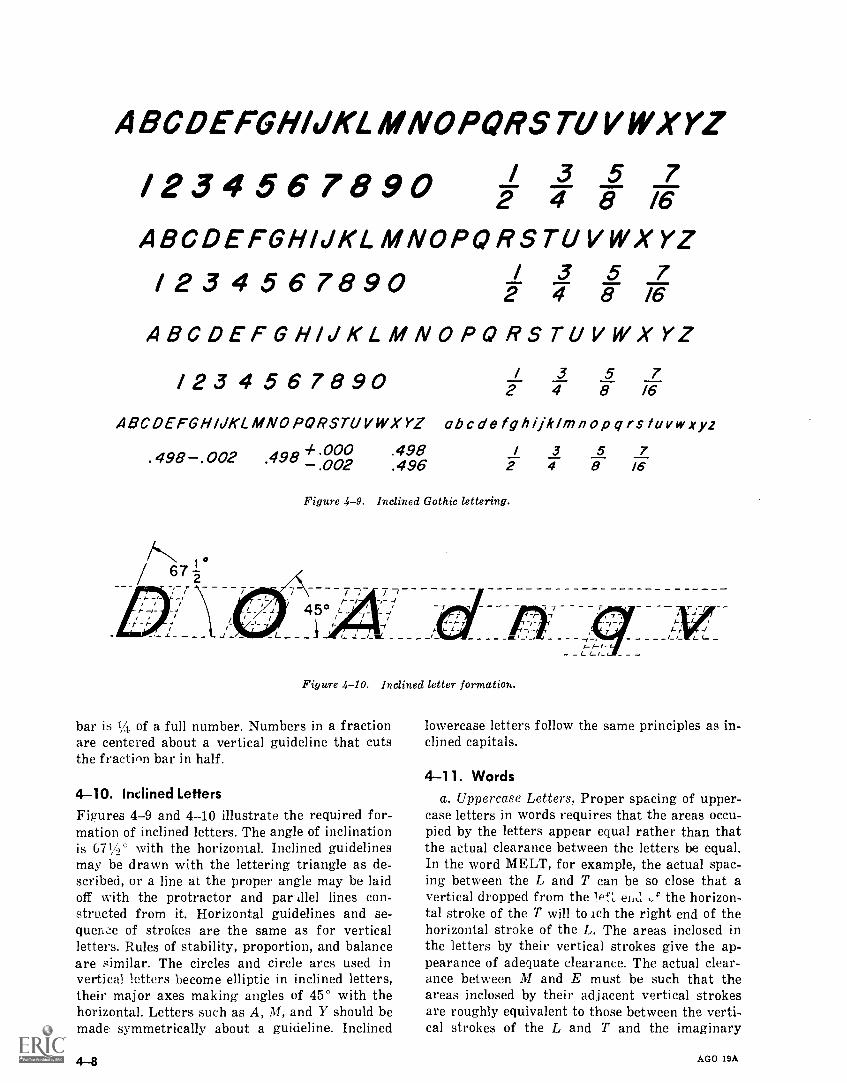
ABODEFGH/JKLMNOPQRSTUVWXYZ
/ 234567890 / 3 5 72 4 8 /6
ABCDEFGHIJKLMNOPORSTUVWXYZ/2 3 4 5 6 7890 / 3 5 7
2 4 8 /6
ABCDEFGH/JKLMNOPORSTUVWXYZ
/23 4 567890 / 3 5 72 4 8 /6
118CDEFGH/KLMNOPORSTUVWXYZ ob c de fg h ijk/m n op q rstuvw xyz
. 498 .002 .498 + .000 .498 3 5 7.002 .496 2 4 8 16
/N 1°2/ 67
Figure 4-9. Inclined Gothic lettering.
45° Lt-t
Figure 4-10. Inclined letter formation.
bar is 14, of a full number. Numbers in a fractionare centered about a vertical guideline that cutsthe fraction bar in half.
4-10. Inclined LettersFigures 4-9 and 4-10 illustrate the required for-mation of inclined letters. The angle of inclinationis 671/2' with the horizontal. Inclined guidelinesmay be drawn with the lettering triangle as de-scribed, or a line at the proper angle may be laidoff with the protractor and par Mel lines con-structed from it. Horizontal guidelines and se-quence of strokes are the same as for verticalletters. Rules of stability, proportion, and balanceare similar. The circles and circle arcs used invertical letters become elliptic in inclined letters,their major axes making angles of 45° with thehorizontal. Letters such as A, M, and Y should bemade symmetrically about a guideline. Inclined
I
lowercase letters follow the same principles as in-clined capitals.
4-11. Wordsa. Uppercase Letters. Proper spacing of upper-
case letters in words requires that the areas occu-pied by the letters appear equal rather than thatthe actual clearance between the letters be equal.In the word MELT, for example, the actual spac-ing between the L and T can be so close that avertical dropped from the lef,, e1tu ,c the horizon-tal stroke of the T will to ich the right end of thehorizontal stroke of the L. The areas inclosed inthe letters by their vertical strokes give the ap-pearance of adequate clearance. The actual clear-ance between M and E must be such that theareas inclosed by their adjacent vertical strokesare roughly equivalent to those between the verti-cal strokes of the L and T and the imaginary
AGO 19A
connecting horizontal strokes of L and T. Actualclearance between E and L can be slightly lessthan that between M and E. The spacing betweenwords should be equivalent to the basic width ofthe letters M and 0.
b. Uppercase and Lowercase Combinations.Spacing between letters in words using eitherlowercase or uppercase and lowercase combina-tions follows the same general rules of word com-position as set forth above. Spacing between linesof lettering on a drawing requires that the clearspace between the dropline and the cap line belowit be equal to 1/3 the distance between the baselineand cap line (or 1/3 the height of capital letters)as established for that drawing. If droplines arenot used, the distance between one baseline andthe cap line below it is equal to 2A the height ofcapital letters as established for that drawing.
c. Spacing Between Words. Spacing betweenwords should be uniform for the entire drawingand is estimated by the space necessary to insert acapital letter I between words. Thus by erasingthe I in WATERIGAP the two words WATERand GAP are properly spaced.
d. Spacing Between Sentences. Spacing betweensentences should be uniform for the entire draw-ing and is a matter of personal choice. For uni-formity, the space necessary to insert a capital M
Section III.
between the period at the end of a sentence andthe first letter of the next sentence is satisfactory.
e. Spacing Between Lines. Spacing betweenlines is described in paragraph 4- 6b(2).
4-12. Title BlocksThe location and size of letters for title blockshave already been described (para 3-8a and 4-6a).The remaining problem is one of composition.Using the space allotted, lines of lettering must bearranged symmetrically about a vertical center-line. First, a satisfactory trial title is worked outon a separate sheet of paper, using guidelinesmarked to equal the space in the title block. Whena satisfactory line of lettering has been achieved;count the number of letters (each space betweenwords also counts as a letter) and mark the mid-point of the line. Draw horizontal and verticalguidelines in the title block of the drawing sheetand establish a vertical centerline. If transparenttracing paper or tracing cloth is used, the trialtitle may be slipped underneath, guidelines andmidpoint alined, and the title traced. If the draw-ing sheet is not transparent, the trial letteringmay be placed directly above the drawing sheetguidelines and centered. The space arrangementworked out on the trial sheet is used as a guide inlettering the drawing sheet title.
MECHANICAL LETTERING
4-13. UseMechanical lettering is executed with a specialpen held in a scriber and guided by a template.The standard lettering set is used for mechanicallettering in military drawings. Because guidelinesare not required, uniform, legible characters canbe produced more rapidly than by freehand meth-ods. Mechanical lettering is used principally fortitle blocks and marginal data for special maps,charts, graphs, and photographs for reproduction.It should be noted that freehand lettering is therequired lettering in drafting ; mechanical letter-ing is confined to the special uses just described.The availability of mechanical lettering devicesshould not deter draftsmen from the daily prac-tice required to execute freehand lettering.
4-14. Standard Lettering SetThe standard lettering set consists of a set oftemplates, a scriber, and a set of pens (fig. 4-11).
a. Templates. Templates are made of laminatedplastic with characters engraved in the face so
AGO 19A
that their component lines are guide grooves forthe scriber. The height of the characters, in thou-sandths of an inch, is given by a number on theupper right-hand side of the template. The rangeof character heights offered by a standard set oftemplates is from 80 (0.008 inch or 5/64th inch)to 500 (0.5 inch or 1A inch). The scale at thebottom of each template has the zero in the centerand is arranged for proper spacing in relation tocharacter heights. The distance between eachscale division represents the area required by anormal letter.
b. Pens. A standard set of pens for producingvarious line weights consists of 10 sizes rangingfrom 00, the finest, to 8N. Each pen is composedof two parts: the ink reservoir and the cleaningpin. The reservoir is a series of connected tubes ofdecreasing diameters, the lowest establishing linethickness. The cleaning pin acts as a valve, pro-truding beyond the edge of the bottom tube whenthe pen is not touching the drawing surface. Inthis position, no ink flows. When the pen is restedon a drawing surface the cleaning pin is pushed
4-9
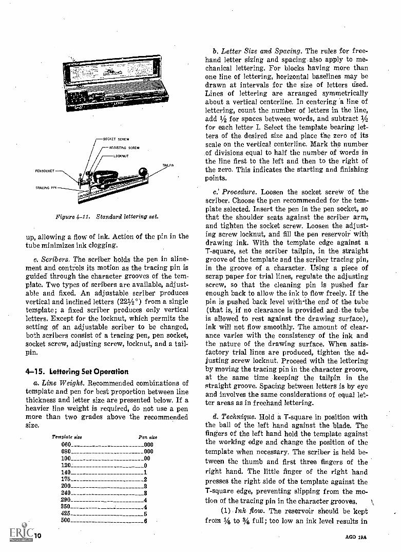
PENSOCKET
TRACING PIN
SOCKET SCREW
ADJUSTING SCREW
LOCKNUT
TAIL PIN
Figure 4-11. Standard lettering aet.
up, allowing a flow of ink. Action of the pin in thetube minimizes ink clogging.
c. Scribers. The scriber holds the pen in aline-ment and controls its motion as the tracing pin isguided through the character grooves of the tem-plate. Two types of scribers are available, adjust-able and fixed. An adjustable scriber producesvertical and inclined letters (221 /2 °) from a singletemplate ; a fixed scriber produces only verticalletters. Except for the locknut, which permits thesetting of an adjustable scriber to be changed,both scribers consist of a tracing pen, pen socket,socket screw, adjusting screw, locknut, and a tail-pin.
4-15. Lettering Set Operationa. Line Weight. Recommended combinations of
template and pen for best proportion between linethickness and letter size are presented below. If aheavier line weight is required, do not use a penmore than two grades above the recommendedsize.
Template size Pen size
060 000080 000100 00120 0140 1175 2200240 3290 4350 4425 5500 6
41-10
b. Letter Size and Spacing. The rules for free-hand letter sizing and spacing also apply to me-chanical lettering. For blocks having more thanone line of lettering, horizontal baselines may bedrawn at intervals for the size of letters used.Lines of lettering are arranged symmetricallyabout a vertical centerline. In centering a line oflettering, count the number of letters in the line,add 1/2 for spaces between words, and subtract 1/2for each letter I. Select the template bearing let-ters of the desired size and place the zero of itsscale on the vertical centerline. Mark the numberof divisions equal to half the number of words inthe line first to the left and then to the right ofthe zero. This indicates the starting and finishingpoints.
c.' Procedure. Loosen the socket screw of thescriber. Choose the pen recommended for the tem-plate selected. Insert the pen in the, pen socket, sothat the shoulder seats against the scriber arm,and tighten the socket screw. Loosen the adjust-ing screw locknut, and fill the pen reservoir withdrawing ink. With the template edge against aT-square, set the scriber tailpin, in the straightgroove of the template and the scriber tracing pin,in the groove of a character. Using a piece ofscrap paper for trial lines, regulate the adjustingscrew, so that the cleaning pin is pushed farenough back to allow the ink to flow freely. If thepin is pushed back level with-the end of the tube(that is, if no clearance is provided and the tubeis allowed to rest against the drawing surface),ink will not flow smoothly. The amount of clear-ance varies with the consistency of the ink andthe nature of the drawing surface. When satis-factory trial lines are produced, tighten the ad-justing screw locknut. Proceed with the letteringby moving the tracing pin in the character groove,at the same time keeping the tailpin in thestraight groove. Spacing between letters is by eyeand involves the same considerations of equal let-ter areas as in freehand lettering.
d. Technique. Hold a T-square in position withthe ball of the left hand against the blade. Thefingers of the left hand hold the template againstthe working edge and change the position of thetemplate when necessary. The scriber is held be-tween the thumb and first three fingers of theright hand. The little finger of the right handpresses the right side of the template against theT-square edge, preventing slipping from the mo-tion of the tracing pin in the character grooves.
(1) Ink flow. The reservoir should be keptfrom 1/4 to 3/4 full; too low an ink level results in
AGO 19A
irregular lines. When the pen is filled and not inuse, it should be placed so that the tip is not incontact with any surface. Before reusing, thecleaning pin should be twirled in the tube toloosen any clotted ink. Never use pressure on a
Section IV. OTHER
4-16. TypingWhen there is an extraordinarily large number oflong notes, they may be typed on transparenttracing paper with a "yellow backing" (an orangecolored carbon used with the carbon facing theback of the tracing paper). Black typing will ap-pear on the front side, and orange typing willappear on the back side in reverse. Type in eitheruppercase or lowercase. After proofreading, ad-here to desired location on transparent tracingpaper with transparent mending tape. In order tocut the typewritten sheet in the exact size andshape of the "hole" in the drawing, place type-written sheet in the desired location, and cut bothsheets at the same time with a razor blade and ametal straightedge. Adhere with the tape andpress firmly and rub so that tape becomes thor-oughly transparent.
AGO 19A
scriber if the ink does not flow. Check the adjust-ing screw setting and the reservoir level.
(2) Fractions. The numbers in a fraction aremade by using a template one size smaller thanthat used for whole numbers.
LETTERING DEVICES
4-17. Printed Title BlocksSome offices provide drawing sheets with the mainheadings and borders of the title block and mar-gin lines already :,;rinted on. The missing informa-tion need only to be added.
4-18. Prepared LetteringPrestype and Zipatone have lettering of variousstyles and sizes printed in reverse on a waxedpaper, that can be transferred simply by rubbinginto position. The Headliner manufactured byVaritype produces various styles and sizes ofprint photographically on 35 mm strips of trans-parent film or opaque paper with or without adhe-sive back.
4-11
CHAPTER 5
ENGINEERING CHARTS AND GRAPHS
Section I. GRAPHIC PRESENTATION OF ENGINEERING DATA
5-1. DefinitionGraphic presentation of engineering data meansusing charts and graphs, rather than numericaltables or work descriptions, to present statisticalengineering information. Properly selected andconstructed, each form of charts and graphs of-fers a sharp, clear, visual statement about a par-ticular aspect of a series of related facts. Thevisual statement either emphasizes the.numericalvalue of the facts or shows the way in which theyare related. A chart or graph that emphasizes nu-merical value is called quantitative; one that em-phasizes relationships is called qualitative. Thetrend of an activity over a period of time, such asthe number of tanks produced over a 10-year pe-riod, is more easily remembered from the shape ofa curve describing the trend than from numericalstatistics. Successful graphic presentation of engi-neering data requires as much drafting ability asthe graphic representation of engineering objects.Lines must be sharp, opaque, well contrasted, andof uniform weight. Letters and figures are nor-mally executed with the standard lettering set inaccordance with the standards presented in chap-ter 4.
5-2. ClassificationGraphs and charts are classified as technicalcharts, display charts, and training aids, accord-ing to the use for which they are intended.
a. Technical Charts. Technical engineeringcharts usually are based on a series of measure-ments of laboratory experiments or work activi-ties. Such measurements examine the quantitativerelationship between a set of two factors, or vari-ables. Of the two variables, one has either a con-trolled or regular variation and is called the inde-pendent variable. The other is called the depend-ent variable, because its values are related to
AGO 19A
those of the independent variable. The line con-necting plotted points is called a curve, although itmay be broken, straight, or curved. The curvedemonstrates the relationship between the varia-bles and permits reading approximate values be-tween plotted points. This type of chart is dis-cussed fully in section II of this chapter.
b. Display Charts. Display charts are draftedprimarily to convey statistical data to nontechni-cal audiences. The message presents a general pic-ture of a situation, usually comparative. Thereare many varieties of display charts, includingbar charts, pictorial charts, pie charts, and train-ing aids. This type of chart is discussed fully insection III of this chapter.
c. Training Aids. Training aids are graphic il-lustrations that assist the instructor in teachingand the students in understanding a point not eas-ily understood verbally. They are usually poster-like in simple bold design, and with some wordingor simple brief text. Training aids are discussedin section IV of this chapter.
5-3. Graphic Aids in Construction WorkAny construction job involves quantities of men,materials, and equipment. Efficient operation andcompletion of the job results from planning, orga-nization, and supervision. Graphic presentation ofdata is important. Statistics of results on pastjobs with similar working conditions provide abasis for predicting the amount of time that aproposed job will take. These statistics offer thebest possibilities for study when presented graph-ically, usually in the form of a curve. The predic-tion of expected achievement usually is presentedas a bar chart and is called a time-and-workschedule. Safety posters are another example ofgraphic aids in construction supervision.. As asupplement to this chapter, refer to DA Pam325-10.
5-1
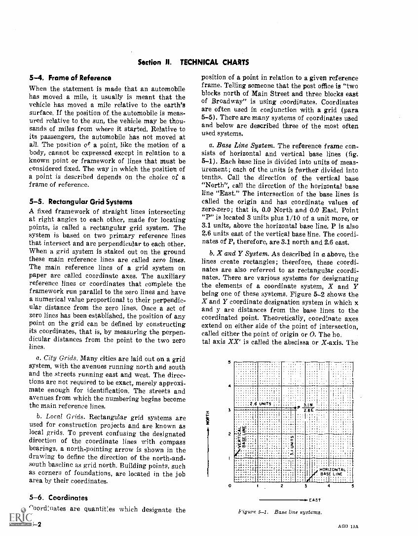
Section II. TECHNICAL CHARTS
5-4. Frame of ReferenceWhen the statement is made that an automobilehas moved a mile, it usually is meant that thevehicle has moved a mile relative to the earth'ssurface. If the position of the automobile is meas-ured relative to the sun, the vehicle may be thou-sands of miles from where it started. Relative toits passengers, the automobile has not moved atall. The position of a point, like the motion of abody, cannot be expressed except in relation to aknown point or framework of lines that must beconsidered fixed. The way in which the position ofa point is described depends on the choice of aframe of reference.
5-5. Rectangular Grid SystemsA fixed framework of straight lines intersectingat right angles to each other, made for locatingpoints, is called a rectangular grid system. Thesystem is based on two primary reference linesthat intersect and are perpendicular to each other.When a grid system is staked out on the groundthese main reference lines are called zero lines.The main reference lines of a grid system onpaper are called coordinate axes. The auxiliaryreference lines or coordinates that complete theframework run parallel to the zero lines and havea numerical value proportional to their perpendic-ular distance from the zero lines. Once a set ofzero lines has been established, the position of anypoint on the grid can be defined by constructingits coordinates, that is, by measuring the perpen-dicular distances from the point to the two zerolines.
a. City Grids. Many cities are laid out on a gridsystem, with the avenues running north and southand the streets running east and west. The direc-tions are not required to be exact, merely approxi-mate enough for identification. The streets andavenues from which the numbering begins becomethe main reference lines.
b. Local Grids. Rectangular grid systems areused for construction projects and are known aslocal grids. To prevent confusing the designateddirection of the coordinate lines with compassbearings, a north-pointing arrow is shown in thedrawing to define the direction of the north-and-south baseline as grid north. Building points, suchas corners of foundations, are located in the jobarea by their coordinates.
5-6. CoordinatesCoordinates are quantities which designate the
5-2
position of a point in relation to a given referenceframe. Telling someone that the post office is "twoblocks north of Main Street and three blocks eastof Broadway" is using coordinates. Coordinatesare often used in conjunction with a grid (para5-5). There are many systems of coordinates usedand below are described three of the most oftenused systems.
a. Base Line System. The reference frame con-sists of horizontal and vertical base lines (fig.5-1). Each base line is divided into units of meas-urement; each of the units is further divided intotenths. Call the direction of the vertical base"North", call the direction of the horizontal baseline "East." The intersection of the base lines iscalled the origin and has coordinate values ofzero-zero ; that is, 0.0 North and 0.0 East. Point"P" is located 3 units plus 1/10 of a unit more, or3.1 units, above the horizontal base line. P is also2.6 units east of the vertical base line. The coordi-nates of P, therefore, are 3.1 north and 2.6 east.
b. X and Y System. As described in a above, thelines create rectangles; therefore, these coordi-nates are also referred to as rectangular coordi-nates. There are various systems for designatingthe elements of a coordinate system, X and Ybeing one of these systems. Figure 5-2 shows theX and Y coordinate designation system in which xand y are distances from the base lines to thecoordinated point. Theoretically, coordinate axesextend on either side of the point of intersection,called either the point of origin or 0. The hoital axis XX' is called the abscissa or X-axis. The
b
5
4
3
2
0
.... . ;..........., .. .....
....., .
.. .....
.
,
. .. . ., . ... . , ..
. . ..: : i :
" .........
.
2 6
I
. .
UNITS1 I
, ..
. , ... . ..
.IN
,
,
; '
t 1, ... t
.1 .. . ..
1
1...1 .
... .
1....
2.6EI
11
1- w 4
L44'-,".(9'.:1:11.--.4...
- .....::',I.;:..1.
- vi....i
4, D..
. .. I.:1. .. I : i .
.. i .. t t . t-;.:111 !-..-- 1.1-4111 i.---
.11-11;7,11.11.-..11:1 111-1:1
........:1. 11:1-] 1, 1. :
r,4:1.
.:. .1.
.. t t
H.t,
Ft ,.. .
r
1 t
1,
HORIZONTAL, BASE
. 1.]:
1 1
1
::LINE . 1
. 1 . 1. : 1
2 3
EAST
Figure 5-1. Base line systems.
4 5
AGO 19A
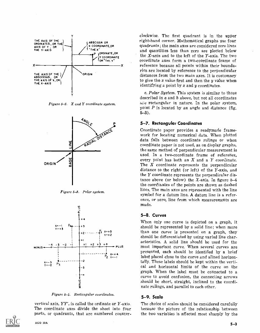
THE AXIS OF THEORDINATES, OR THEAXIS OF Y , ORTHE Y -AXIS
ABSCISSA ORX COORDINATE,OR
THE X"p IORDINATE,OR
l`f COORDINATEOR "THE Y"
ABSCISSAS, OR )THE AXIS OF THE
THE AXIS OF XTHE X-AXIS
MINUS
ORIGIN
Figure 5-2. X and Y coordinate system.
clockwise. The first quadrant is in the upperright-hand corner. Mathematical graphs use fourquadrants; the main axes are considered zero linesand quantities less than zero are plotted belowthe X-axis and to the left of the Y-axis. The twocoordinate axes form a two-coordinate frame ofreference because all points within their bounda-ries are located by reference to the perpendiculardistances from the two main axes. It is customaryto give the x value first and then the y value whenidentifying a point by x and y coordinates.
c. Polar System. This system is similar to thosedescribed in a and b above, but not all coordinateshre rectangular in nature. In the polar system,point P is located by an angle and distance (fig.5-3).
P 5-7. Rectangular CoordinatesCoordinate paper provides a readymade frame -
Pr for locating numerical data. When plotteddata falls between coordinate rulings or whencoordinate paper is not used, as on display graphs,the same method of perpendicular measurement isused. In a two-coordinate frame of reference,every point has both an X and a Y coordinate.
ORIGINco The X coordinate represents the perpendicular
Figure 5-3. Polar system.
U)
-J
+4
Dz
Figure 5-4. Rectangular coordinates.
vertical axis, YY', is called the ordinate or Y-axis.The coordinate axes divide the sheet into fourparts, or quadrants, that are numbered counter-
AGO 19A
distance to the right (or left) of the Y-axis, andthe Y coordinate represents the perpendicular dis-tance above (or below) the X-axis. In figure 5-4the coordinates of the points are shown as dashedlines. The main axes are represented with the linesymbol for a datum line. A datum line is a refer-ence, or zero, line from which measurements aremade.
5-8. CurvesWhen only one curve is depicted on a graph, itshould be represented by a solid line ; when morethan one curve is presented on a graph, theyshould be differentiated by using varied line char-acteristics. A solid line should be used for themost important curve. When several curves arepresented, each should be identified by a brieflabel placed close to the curve and alined horizon-tally. These labels should be kept within the verti-cal and horizontal limits of the curve on thegraph. When the label must be connected to acurve to avoid confusion, the connecting arrowsshould be short, straight, inclined to the coordi-nate rulings, and parallel to each other.
5-9. Scale
The choice of scales should be considered carefullybecause the picture of the relationship betweenthe two variables is affected most sharply by the
5-3
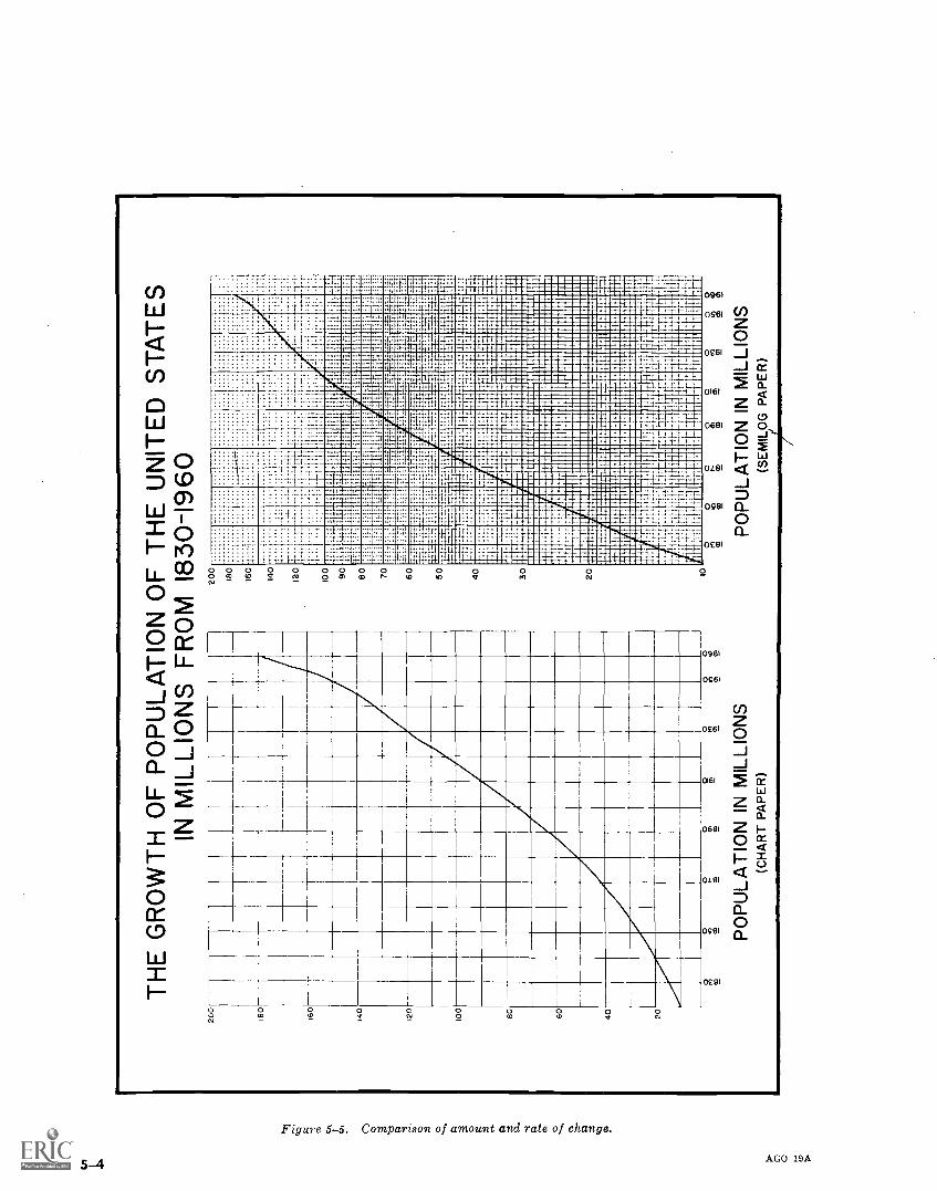
TH
E G
RO
WT
H O
F P
OP
ULA
TIO
N O
F T
HE
UN
ITE
D S
TA
TE
SIN
MIL
LIO
NS
FR
OM
183
0-19
60-1
w
H
00
00
0o
200
200
18 16 140
120
100
80 60 40 20
PO
PU
LAT
ION
IN M
ILLI
ON
S(C
HA
RT
PA
PE
R)
180
160
140
120
100 90 60 70 60 50 40 30 20 10
0
1
......
.....
:...
....
......
...
.....
.....
.
. ..
..
......
...
:.t
....
...._
.....
....
...
,
ram
tran
amiu
mm
inum
r.A
wm
gram
mum
mas
anim
mili
mm
inIN
EE
RW
M11
--,,
`-'7
1
RE
HMt-t-
1 i'
'1-
IME
MIIM
ME
NE
NN
IMM
't-W
IMU
LIE
BIn
INIM
ilffi
ll
,
1
,4 M
EE
1rt
KIN
IZN
IEN
IME
RIO
NU
MN
IM
EM
ER
INE
MFA
MN
EM
EIM
MB
I
NM
..M.
ME
Eki
ridl
iZin
iiiiii
iiIM
EE
MM
ilffi
niM
niaM
aiiii
iE
V
IMM
IIII
NFA
SIB
UN
IIIM
PIN
IMM
EI
INK
IEW
ININ
NE
ffri
arif
filiM
MIM
EIn
iffilM
all
1M
.....
ii 1
urgi
min
imun
non:
6..P
AR
TE
RM
Iad
..LI
OT
hIN
I112
1....
..ffl
crud
Em
Em
....
inip
Mrm
illIM
IIII
MM
PIlli
pm11
1111
1111
1111
1111
1111
1111
0m
ala-
a mum4 K
.....a
ynna
-ana
lual
sim
iogr
annu
rra
Ali
,1-u
mpa
nsfi
rani
mqi
..anA
wir
..r.o
rmai
mum
-rom
umuh
lii...
......
.uhr
:
ga"
num
ur.
IIm
ajui
i Fli..1 ur
id in
j:...
On
tram
:
"
ai i
NI "M
Ili n
ili
...in
i:nni
srila
stm
etm
anun
sin
--.-
....E
.-a
SW
u
umou
nhah
ill
I null.. .
...ea
ni
""--
eio
n. r_r.
'T
.- 1_,
,t
06ru
m&
rm.
ii t t 1
umni
nliii
du.
.it 1
'4 t In..4,
_
. ' g rimi
1it
,i-;
__,_ i 4
IT uII
I, ,' t '
1
__
tt
44
II0 co
0 co
PO
PU
LAT
ION
IN M
ILLI
ON
S(S
EM
ILO
G P
AP
ER
)
0 T
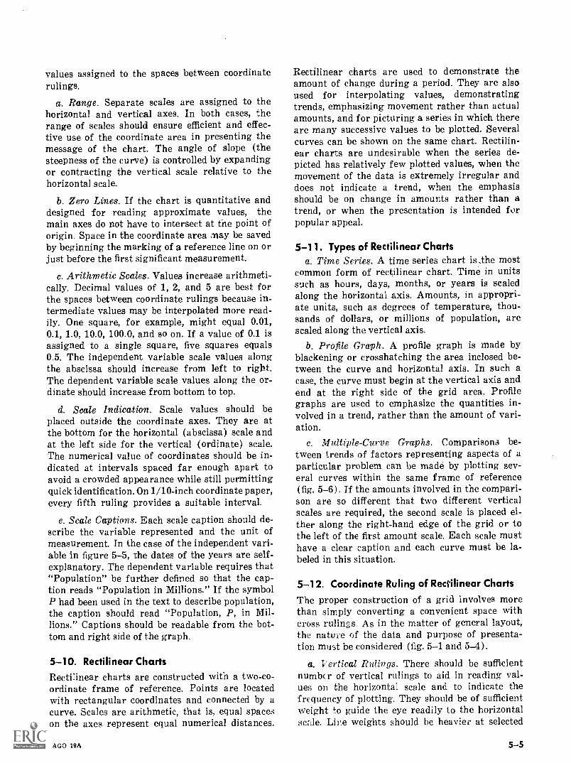
values assigned to the spaces between coordinaterulings.
a. Range. Separate scales are assigned to thehorizontal and vertical axes. In both cases, therange of scales should ensure efficient and effec-tive use of the coordinate area in presenting themessage of the chart. The angle of slope (thesteepness of the curve) is controlled by expandingor contracting the vertical scale relative to thehorizontal scale.
b. Zero Lines. If the chart is quantitative anddesigned for reading approximate values, themain axes do not have to intersect at the point oforigin. Space in the coordinate area may be savedby beginning the marking of a reference line on orjust before the first significant measurement.
c. Arithmetic Scales. Values increase arithmeti-cally. Decimal values of 1, 2, and 5 are best forthe spaces between coordinate rulings because in-termediate values may be interpolated more read-ily. One square, for example, might equal 0.01,0.1, 1.0, 10.0, 100.0, and so on. If a value of 0.1 isassigned to a single square, five squares equals0.5. The independent variable scale values alongthe abscissa should increase from left to right.The dependent variable scale values along the or-dinate should increase from bottom to top.
d. Scale Indication. Scale values should beplaced outside the coordinate axes. They are atthe bottom for the horizontal (abscissa) scale andat the left side for the vertical (ordinate) scale.The numerical value of coordinates should be in-dicated at intervals spaced far enough apart toavoid a crowded appearance while still permittingquick identification. On 1/10-inch coordinate paper,every fifth ruling provides a suitable interval.
e. Scale Captions. Each scale caption should de-scribe the variable represented and the unit ofmeasurement. In the case of the independent vari-able in figure 5-5, the dates of the years are self-explanatory. The dependent variable requires that"Population" be further defined so that the cap-tion reads "Population in Millions." If the symbolP had been used in the text to describe population,the caption should read "Population, P, in Mil-lions." Captions should be readable from the bot-tom and right side of the graph.
5 -10. Rectilinear ChartsRectilinear charts are constructed with a two-co-ordinate frame of reference. Points are locatedwith rectangular coordinates and connected by acurve. Scales are arithmetic, that is, equal spaceson the axes represent equal numerical distances.
AGO 19A
Rectilinear charts are used to demonstrate theamount of change during a period. They are alsoused for interpolating values, demonstratingtrends, emphasizing movement rather than actualamounts, and for picturing a series in which thereare many successive values to be plotted. Severalcurves can be shown on the same chart. Rectilin-ear charts are undesirable when the series de-picted has relatively few plotted values, when themovement of the data is extremely irregular anddoes not indicate a trend, when the emphasisshould be on change in amounts rather than atrend, or when the presentation is intended forpopular appeal.
5-1 1 . Types of Rectilinear Chartsa. Time Series. A time series chart is,the most
common form of rectilinear chart. Time in unitssuch as hours, days, months, or years is scaledalong the horizontal axis. Amounts, in appropri-ate units, such as degrees of temperature, thou-sands of dollars, or millions of population, arescaled along the vertical axis.
b. Profile Graph. A profile graph is made byblackening or crosshatching the area inclosed be-tween the curve and horizontal axis. In such acase, the curve must begin at the vertical axis andend at the right side of the grid area. Profilegraphs are used to emphasize the quantities in-volved in a trend, rather than the amount of vari-ation.
c. Multiple-Curve Graphs. Comparisons be-tween trends of factors representing aspects of aparticular problem can be made by plotting sev-eral curves within the same frame of reference(fig. 5-6). If the amounts involved in the compari-son are so different that two different verticalscales are required, the second scale is placed ei-ther along the right-hand edge of the grid or tothe left of the first amount scale. Each scale musthave a clear caption and each curve must be la-beled in this situation.
5-12. Coordinate Ruling of Rectilinear ChartsThe proper construction of a grid involves morethan simply converting a convenient space withcross rulings. As in the matter of general layout,the nature of the data and purpose of presenta-tion must be considered (fig. 5-1 and 5-4).
a. T ertical Rulings. There should be sufficientnumber of vertical rulings to aid in reading val-ues on the horizontal scale and to indicate thefrequency of plotting. They should be of sufficientweight fo guide the eye readily to the horizontalscale. Lire weights should be heavier at selected
5-5
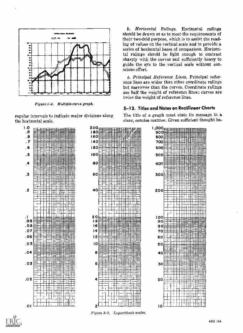
..
a I
al
a,
.'
. l inom
m!=
i==
iI
u..a-
"zi=.t
pmosgar.=
. nnali2==
' ..m
Ergel=
1...
liem
esumm
e.
ilnuuwluuD
untl .... 111111111111 llllllllllllin21§1E
ZZ
IMinopH
IMM
INIM
MIm
m".610
llasm
imm
aimii.
imom
mm
aimaii
1111111111111111111113111111111111111111111111111MB
ION
SIIIIM
1=11111111111111111111
MI1111111111A
MM
LITIM
IMIN
IMM
OM
=t11111111111111M
MM
1111111111MH
IMM
U11110IM
IMM
IN111111111 llllllll m
eiumm
lumunm
uspe. sosiginolumr idnini IM
Enim
mi
ris "m.
ffl lllllllllll..ilim
umm
inumuninum
mus...m
mum
minim
ilimm
ilmiim
mulim
umum
.... ..........m
ilimm
lin milm
ilinumm
nimm
umm
........filimm
uumm
illempluom
umm
mum
NE
i.....ilim
illimill m
mum
miiim
mulim
umm
umom
milm
umilum
uniumunum
mlium
mum
m...
thimpum
aimuim
minim
mum
mum
mom
mm
mum
mium
mom
mum
munm
annnomm
ulmE
imum
miim
inimm
umm
ulimiiiiiiim
iimpim
mm
uussomm
ouniiiimm
ipmum
niiiiiimium
npunimm
omIm
mo
1111111111111 111111111111111111111111 1 11111111111M
111111111111111111111111111111 111111111111111111111111m*1111111111111111 1111E
1111
MliiiiiiiM
inialimiliiiiiiiiiiiiiiiiddlum
MIN
EN
EN
EN
iumuniiiiiinim
ilimm
enffid114filimm
oN
om.
111111111111 111111111111111111111111
11111n11111111111111110111111i1111111111111101i1111111111111111111111i111111111111111011-
......
..
.......
..
.......
..
.. .
5I
.
ii
..mm
or.
mm
mnnll llM
mm
m
SIIII M
MIS
- - -===
sue = M
m Ei
UM
Wll ..2:112._2_=
:==
=1....s
.12.nu;III
1153-1F:"
iIIl
11:1112
1
Ilnl"iiiM
bi_i
lill
Ol
Fglllll
11111lll u.
SLI
M1N
. =a=
lll n"
mm
irp
.= N
fe./11110llll Min 1111M
IMM
IMum
iumm
ouldliiiiimim
ilIM i
mu m
mom
mm
omillm
iiiltimiM
gumiiiim
eil111111 m
MN
MM
n1um iiIm
milm
iiiiiiiimilinlllll B
r lMO
IIIMIE
MB
M1111111111m
assessmusum
nimsussum
sugnmum
m11111M
1111111111111M111111111111111111H
imV
Ir Mm
umr111111111l11u111e11111u1 11i1111111u1111num
mm
urmm
omog
111111111111111111111111111111111111111M111111111 IIIIM
11=
11111111111111111111111111111111111111 I IIIIIIIIIM
ME
MO
Imim
ilmilhim
mIlom
mim
plumnurium
mum
mollum
mulpim
mom
mm
ulmim
ilmm
lomm
Eim
m1
mum
minum
muum
unimulm
munum
mosum
Em
mintim
mium
unumm
muun tum
uompsium
ml
Imm
illuldirnimum
mlli11111111111 pium
mussom
muum
buimilim
mm
umppiim
unimm
umum
IIIIIIMM
IIIIIIIIIIIIIIM1111111111111pffiffill IIIIIIIIIIIIIN
IMIIIIIIIIIInigiiiiiM
u111111111111111u01111111111111111111MM
E1111111111 11111111111111111111111111111111111111111111111111111111
11111111111111M111111111111M
111 11111111111111111111111111111EN
1111......
..
.. .
..
..
..
...
IIlll :T
MIM
I I
1lVA
IMM
uMM
EIM
inal
II IIII M
O
slainglaV arlilnaMn
:LW
11111 RE
SE
MI
ll 9.......mo
U.
pos..l .mA
....--SS
Gson=
mm
:u...m
mem
iluil llllllls
llll sasmarom
m m
owiui
gmi
eimem
umm
mism
umium
amm
issimm
ullimm
umnusseam
mum
=111111111111111111M
111111111111111MIIIIIIIIIM
MN
=111111111n111111111111110111H
111110111111MIIIM
E 11M
M11iiiiiM
ill11MIM
MO
MM
EN
IMM
MN
M111111111111111111111111111111111111111M
UM
NE
M..
.M
I MU
M° IIIIM
M1111111fili IIIM
MU
MN
IMM
INIO
NIM
111111 MIM
IIMM
IMM
IIIMM
MO
MM
IIMM
EM
IN M
,11111111111111111111111111111111111111111111111111U
MM
INIIIIM
ME
M11111111111111111111111111111111111111111111111111U
MM
IEN
IMM
EM
,
111111111111M111111111111111111111111111111111111U
NIM
UM
ME
MN
1111111111111111111111111111111111111111111MM
UM
EN
NIM
TM
1111111111111111111111111111111111111111111111111111111111MM
INIM
111111111111M1111111111111111111111111111111111m
11111M
E111111111111111111111111111111111111111111111111111111111M
IEM
ON
111111111111ifi011111111111111111111111111111111111P111
11111111111011111111111111111M1IIM
MH
11HI111111II01M
E1N
M111111111IM
IH1M
11I11I1MM
b11II11I111MI1111M
I1s=M
ED
I
D
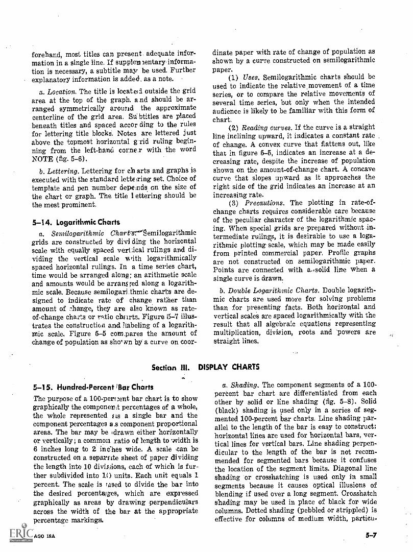
forehand, most titles can present adequate infor-mation in a single line. If supple ientary informa-tion is necessary, a subtitle may be used. Furtherexplanatory information is added, as a note.
a. Location. The title is located outside the gridarea at the top of the graph. a nd should be ar-ranged symmetrically around the approximatecenterline of the grid area. Su btitles are placedbeneath titles and spaced accor ding to the rulesfor lettering title blocks. Notes are lettered justabove the topmost horizontal g rid ruling begin-ning from the left-hand cornea with the wordNOTE (fig. 5-6).
b. Lettering. Lettering for ch arts and graphs isexecuted with the standard lettering set. Choice oftemplate and pen number depends on the size ofthe chart or graph. The title I ettering should bethe most prominent.
5-14. Logarithmic Chartsa. Semilogarithmic ChartTriemilogarithmic
grids are constructed by dii ding the horizontalscale with equally spaced vertical rulings and di-viding the vertical scale Ai rith logarithmicallyspaced horizontal rulings. In a time series chart,time would be arranged along; an arithmetic scaleand amounts would be arranged along a logarith-mic scale. Because semilogari thmic charts are de-signed to indicate rate of change ratifier thanamount of .;thange, they are also known as rate-of-change charts or ratio charts. Figure 15-7 illus-trates the construction and ]labeling of a logarith-mic scale. Figure 5-5 compares the amount ofchange of population as sho, wn by a curve on coor-
Section HI.
5-15. Hundred-Percent !Bar ChartsThe purpose of a 100 - percent bar chart is to showgraphically the componer Lt percentages of a whole,the whole represented as a single bar and thecomponent percentages a ,s component proportionalareas. The bar may be drawn either horizontallyor vertically; a common ratio of length to -ovidth is6 inches long to 2 inches wide. A scale can beconstructed on a separate sheet of paper dividingthe length into 10 divthions, each of which is fur-ther subdivided into 10 units. Each unit equals 1percent. The scale is Timed to divide the bar intothe desired percentages, which are expressedgraphically as areas by drawing perpendicularsacross the width of the bar at the appropriatepercentage markings.
AGO 19A
dinate paper with rate of change of population asshown by a curve constructed on semilogarithmicpaper.
(1) Uses. Semilogarithmic charts should beused to indicate the relative movement of a timeseries, or to compare the relative movements ofseveral time series, but only when the intendedaudience is likely to be familiar with this form ofchart.
(2) Reading curves. If the curve is a straightline inclining upward, it indicates a constant rateof change. A convex curve that flattens out, likethat in figure 5-5, indicates an increase at a de-creasing rate, despite the increase of populationshown on the amount-of-change chart. A concavecurve that slopes upward as it approaches theright side of the grid indicates an increase at anincreasing rate.
(3) Precautions. The plotting in rate-of-change charts requires considerable care becauseof the peculiar character of the logarithmic spac-ing. When special grids are prepared without in-termediate rulings, it is desirable to use a loga-rithmic plotting scale, which may be made easilyfrom printed commercial paper. Profile graphsare not constructed on semilogarithmic paper.Points are connected with asolid line when asingle curve is drawn.
b. Double Logarithmic Charts. Double logarith-mic charts are used more for solving problemsthan for presenting facts. Both horizontal andvertical scales are spaced logarithmically with theresult that all algebraic equations representingmultiplication, division, roots and powers arestraight lines.
DISPLAY CHARTS
a. Shading. The component segments of a 100 -percent bar chart are differentiated from eachother by solid or line shading (fig. 5-8). Solid(black) shading is used only in a series of seg-mented 100-percent bar charts. Line shading par-allel to the length of the bar is easy to construct;horizontal lines are used for horizontal bars, ver-tical lines for vertical bars. Line shading perpen-dicular to the length of the bar is not recom-mended for segmented bars because it confusesthe location of the segment limits. Diagonal lineshading or crosshatching is used only in smallsegments because it causes optical illusions ofblending if used over a long segment. Crosshatchshading may be used in place of black for widecolumns. Dotted shading (pebbled or strippled) iseffective for columns of medium width, particu-
5-7
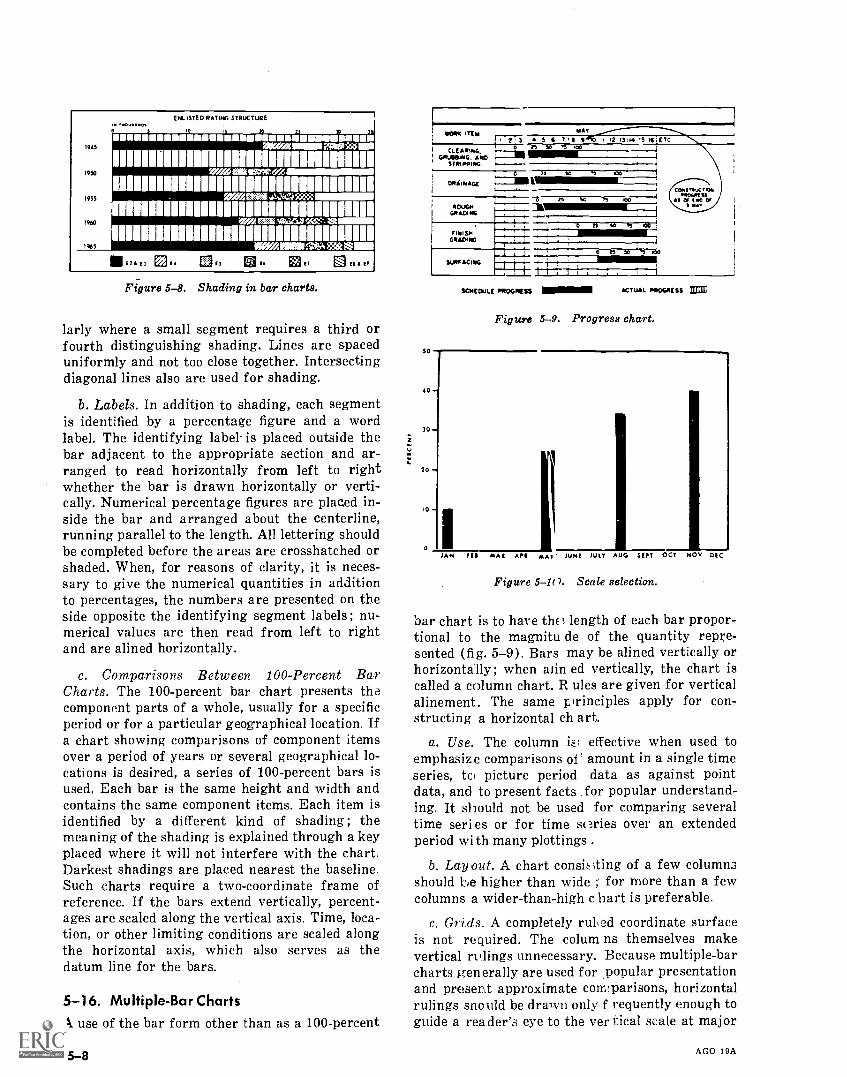
1945
19S0
1955
1960
1965
1.00V1101.ENLISTED RATING. STRUCTURE
imallummog'mulimullumpRip
onumummuunlloE17 El E3E. ..;41 El ES
Figure 5-8. Shading in bar charts.
larly where a small segment requires a third orfourth distinguishing shading. Lines are spaceduniformly and not too close together. Intersectingdiagonal lines also are used for shading.
b. Labels. In addition to shading, each segmentis identified by a percentage figure and a wordlabel. The identifying label is placed outside thebar adjacent to the appropriate section and ar-ranged to read horizontally from left to rightwhether the bar is drawn horizontally or verti-cally. Numerical percentage figures are placed in-side the bar and arranged about the centerline,running parallel to the length. All lettering shouldbe completed before the areas are crosshatched orshaded. When, for reasons of clarity, it is neces-sary to give the numerical quantities in additionto percentages, the numbers are presented on theside opposite the identifying segment labels ; nu-merical values are then read from left to rightand are alined horizontally.
c. Comparisons Between 100-Percent BarCharts. The 100-percent bar chart presents thecomponent parts of a whole, usually for a specificperiod or for a particular geographical location. Ifa chart showing comparisons of component itemsover a period of years or several geographical lo-cations is desired, a series of 100-percent bars isused. Each bar is the same height and width andcontains the same component items. Each item isidentified by a different kind of shading ; themeaning of the shading is explained through a keyplaced where it will not interfere with the chart.Darkest shadings are placed nearest the baseline.Such charts require a two-coordinate frame ofreference. If the bars extend vertically, percent-ages are scaled along the vertical axis. Time, loca-tion, or other limiting conditions are scaled alongthe horizontal axis, which also serves as thedatum line for the bars.
5-16. Multiple-Bar ChartsA use of the bar form other than as a 100-percent
5-8
SO
VORA ITEie2'S 5 6 T'S 12 I3 HI I5.I{I ETC
GRUBBING. AND -STRIPPING
MAY
DRAINAGE
ROUGHGRADING
FINISHGRADING
se
SO n
6 n S6 TS AO
0 TS So h 100
fir.
[Gangue TKOTOOGN ISS
161 Of INS OfIslas
SCHEDULE PROGRESS 1.11.11...1 ACTUAL PROGRESS
Figure 5-9. Progress chart.
111111111
4 0 4.
3 0 -4
70 -
10
O
IAN Ill
Figure 5-10. Scale selection.
bar chart is to have th1 length of each bar propor-tional to the magnitu de of the quantity repre-sented (fig. 5-9). Bars may be alined vertically orhorizontally; when alias ed vertically, the chart iscalled a column chart. R ules are given for verticalalinement. The same principles apply for con-structing a horizontal ch art.
a. Use. The column is; effective when used toemphasize comparisons of amount in a single timeseries, tc, picture period data as against pointdata, and to present facts for popular understand-ing. It should not be used for comparing severaltime series or for time series over an extendedperiod with many plottings .
b. Layout. A chart consis;ting of a few columnsshould be higher than wide ; for more than a fewcolumns a wider-than-high c hart is preferable.
c. Grids. A completely ruled coordinate surfaceis not required. The colum ns themselves makevertical nulings unnecessary. Because multiple-barcharts generally are used for .popular presentationand present approximate comparisons, horizontalrulings snould be drawn only frequently enough toguide a reader's eye to the vertical scale at major
AGO 19A
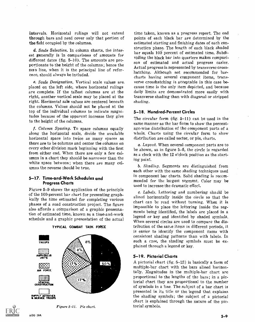
intervals. Horizontal rulings will not extendthrough bars and need cover only that portion ofthe field occupied by the columns.
d. Scale Selection. In column charts, the inter-est generally is in comparisons of amounts fordifferent dates (fig. 5-10). The amounts are pro-portionate to the height of the columns ; hence thezei o line, when it is the principal line of refer-ence, should always be included.
e. Scale Designation. Vertical scale values areplaced on the left side, where horizontal rulingsare complete. If the tallest columns are at theright, another vertical scale may be placed at theright. Horizontal sale values are centered beneaththe columns. Values should not be placed at thetop of the individual columns to indicate magni-tudes because of the apparent increase they giveto the height of the columns.
1. Column Spacing. To space columns equallyalong the horizontal scale, divide the availablehorizontal space into twice as many spaces asthere are to be columns and center the columns onevery other division mark beginning with the firstfrom either end. When there are only a few col-umns in a chart they should be narrower than thewhite space between ; when there are many col-umns the reverse should be true.
5-17. Time-and-Work Schedules andProgress Charts
Figure 5-9 shows the application of the principleof the 100-percent bar chart for presenting graph-ically the time estimated for completing variousphases of a road construction project. The figurealso affords a comparison of a graphic presenta-tion of estimated time, known as a time-and-workschedule and a graphic presentation of the actual
TYPICAL COMBAT TASK FORCE
TROOPS
'142ANIPHI810:-IS
UNITS
req.-AIR FORCE
1111111111
codillitko
SUPPLY ACTIVITIESII SERVICE TROOPS
AGO 19A
Figure 5-11. Pie chart.
time taken, known as a progress report. The endpoints of each black bar are determined by theestimated starting and finishing dates of each con-struction phase. The length of each black shadedbar equals 100 percent of estimated time. Subdi-viding the black bar into quarters makes compari-son of estimated and actual progress easier.Actual progress is represented by transverse cross-hatching. Although not recommended for bar-charts having several component items, trans-verse crosshatching is acceptable in this case be-cause time is the only item depicted, and becausedaily limits are demonstrated more easily withtransverse shading than with diagonal or strippedshading.
5 -18. Hundred-Percent Circles
The circular form (fig. 5-11) can be used in thesame manner as the bar form to show the percent-age-wise distribution of the component parts of awhole. Charts using the circular form to showdistribution are called sector, or pie, charts.
a. Layout. When several component parts are tobe shown, as in figure 5-5, the circle is regardedas a clock with the 12 o'clock position as the start-ing point.
b. Shading. Segments are distinguished fromeach other with the same shading techniques usedin component bar charts. Solid shading is recom-mended for the largest segment. Color may beused to increase the dramatic effect.
c. Labels. Lettering and numbering should bealined horizontally inside the circle so that thechart can be read without turning. When it isimpossible to place the lettering inside the seg-ments being identified, the labels are placed in alegend or key and identified by shaded symbols.When several circles are used to compare the dis-tribution of the same items in different periods, itis easier to identify the component items withconsistent shading patterns than with labels. Insuch a case, the shading symbols must be ex-plained through a legend or key.
5--19. Pictorial ChartsA pictorial chart (fig. 5-12) is basically a form ofmultiple-bar chart with the bars alined horizon-tally. Magnitudes in the multiple-bar chart areproportional to the lengths of the bars ; in a pic-torial chart they are proportional to the numberof symbols in a line. The subject of a bar chart ispresented in its title or the legend that explainsthe shading symbols ; the subject of a pictorialchart is explained through the nature of the pic-torial symbols.
5-9
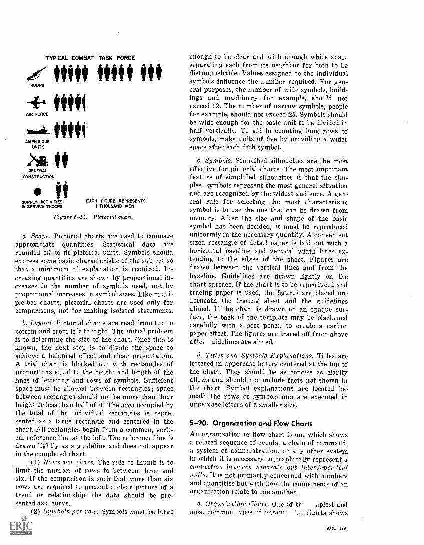
TYPICAL COMBAT TASK FORCE
Stiff MIS Of+t filli
AIR FORCE
AMPHIBIOUSUNITS
GENERAL
CONSTRUCTION
fiSUPPLY- ACTIVITIESa SERVICE TROOPS 1 THOUSAND MEN
EACH FIGURE REPRESENTS
Figure 5-12. Pictorial chart.
a. Scope. Pictorial charts are used to compareapproximate quantities. Statistical data arerounded off to fit pictorial units. Symbols shouldexpress some basic characteristic of the subject sothat a minimum of explanation is required. In-creasing quantities are shown by proportional in-creases in the number of symbols used, not byproportional increases in symbol sizes. Like multi-ple-bar charts, pictorial charts are used only forcomparisons, not for making isolated statements.
b. Layout. Pictorial charts are read from top tobottom and from left to right. The initial problemis to determine the size of the chart. Once this isknown, the next step is to 'divide the space toachieve a balanced effect and clear presentation.A trial chart is blocked out with rectangles ofproportions equal to the height and length of thelines of lettering and rows of symbols. Sufficientspace must be allowed between rectangles; spacebetween rectangles should not be more than theirheight or less than half of it. The area occupied bythe total of the individual rectangles is repre-sented as a large rectangle and centered in thechart. All rectangles begin from a common, verti-cal reference line at the left. The reference line isdrawn lightly as a guideline and does not appearin the completed chart.
(1) Rows per chart. The rule of thumb is tolimit the number of rows to between three andsix. If the comparison is such that more than sixrows are required to pre: lent a clear picture of atrend or relationship, the data should be pre-sented as a curve.
(2) Symbols per row. Symbols must be lf.rge
5 -10
enough to be clear and with enough white spas.separating each from its neighbor for both to bedistinguishable. Values assigned to the individualsymbols influence the number required. For gen-eral purposes, the number of wide symbols, build-ings and machinery for example, should notexceed 12. The number of narrow symbols, peoplefor example, should not exceed 25. Symbols shouldbe wide enough for the basic unit to be divided inhalf vertically. To aid in counting long rows ofsymbols, make units of five by providing a widerspace after each fifth symbol.
c. Symbols. Simplified silhouettes are the mosteffective for pictorial charts. The most importantfeature of simplified silhouettes is that the sim-ples symbols represent the most general situationand are recognized by the widest audience. A gen-eral rule for selecting the most characteristicsymbol is to use the one that can be drawn frommemory. After the size and shape of the basicsymbol has been decided, it must be reproduceduniformly in the necessary quantity. A convenientsized rectangle of detail paper is laid out with ahorizontal baseline and vertical width lines ex-tending to the edges of the sheet. Figures aredrawn between the vertical lines and from thebaseline. Guidelines are drawn lightly on thechart surface. If the chart is to be reproduced andtracing paper is used, the figures are placed un-derneath the tracing sheet and the guidelinesalined. If the chart is drawn on an opaque sur-face, the back of the template may be blackenedcarefully with a soft pencil to create a carbonpaper effect. The figures are traced off from aboveafter uidelines are alined.
d. Titles and Symbols Explanations. Titles arelettered in uppercase letters centered at the top ofthe chart. They should be as concise as clarityallows and should not include facts not shown inthe chart. Symbol explanations are located be-neath the rows of symbols and are executed inuppercase letters of a smaller size.
5-20. Organization and Flow ChartsAn organization or flow chart is one which showsa related sequence of events, a chain of command,a system of administration, or any other systemin which it is necessary to graphically represent aconnection between separate but interdependentunits. It is not primarily concerned with numbersand quantities but with how the compc nents of anorganization relate to one another.
a. Organization Chart. One of tl- oplest andmost common types of organi7 charts shows
AGO 19A
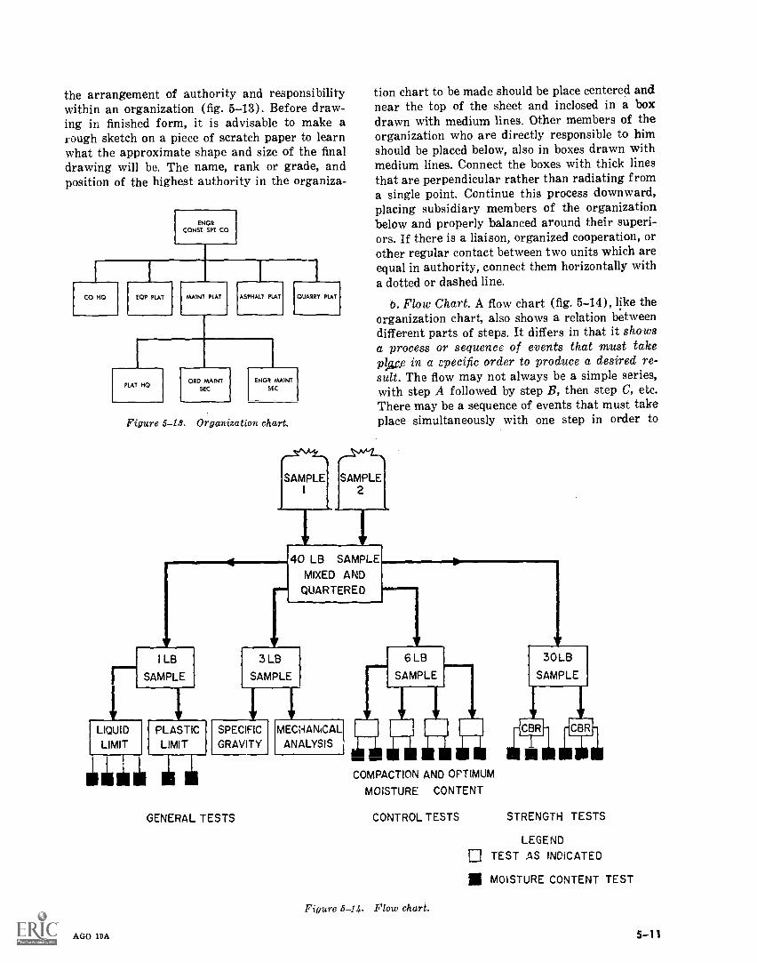
the arrangement of authority and responsibilitywithin an organization (fig. 5-13), Before draw-ing in finished form, it is advisable to make arough sketch on a piece of scratch paper to learnwhat the approximate shape and size of the finaldrawing will be. The name, rank or grade, andposition of the highest authority in the organiza-
CO HO EOP PLAT
ENGRCONST SPT CO
MAINT PLAT ASPHALT PLAT
PLAT HOORD MAINT
SEC
QUARRY PLAT
ENGR MAINTSEC
Figure 5-18. Organization chart.
I LB
SAMPLE
4
SAMPLE
tion chart to be made should be place centered andnear the top of the sheet and inclosed in a boxdrawn with medium lines. Other members of theorganization who are directly responsible to himshould be placed below, also in boxes drawn withmedium lines. Connect the boxes with thick linesthat are perpendicular rather than radiating froma single point. Continue this process downward,placing subsidiary members of the organizationbelow and properly balanced around their superi-ors. If there is a liaison, organized cooperation, orother regular contact between two units which areequal in authority, connect them horizontally witha dotted or dashed line.
b. Flow Chart. A flow chart (fig. 5-14), like theorganization chart, also shows a relation betweendifferent parts of steps. It differs in that it showsa process or sequence of events that must takeplace in a specific order to produce a desired re-sult. The flow may not always be a simple series,with step A followed by step B, then step C, etc.There may be a sequence of events that must takeplace simultaneously with one step in order to
SAMPLE2
---F ---F4 0 LI) B M
MIXED
SAMPLEP L E
QUARTERED
3 LB
SAMPLE
MECHANICAL1LIQUID PLASTIC SPECIFIC
LIMIT LIMIT GRAVITY ANALYSIS
GENERAL TESTS
AGO 19A
6 LB
SAMPLE
COMPACTION AND OPTIMUM
MOISTURE CONTENT
30 LB
SAMPLE
-jCBR
111111illi
CBR.
CONTROL TESTS STRENGTH TESTS
Figure 5-14. Flow chart.
LEGEND
TEST AS INDICATED
al MOISTURE CONTENT TEST
5-H
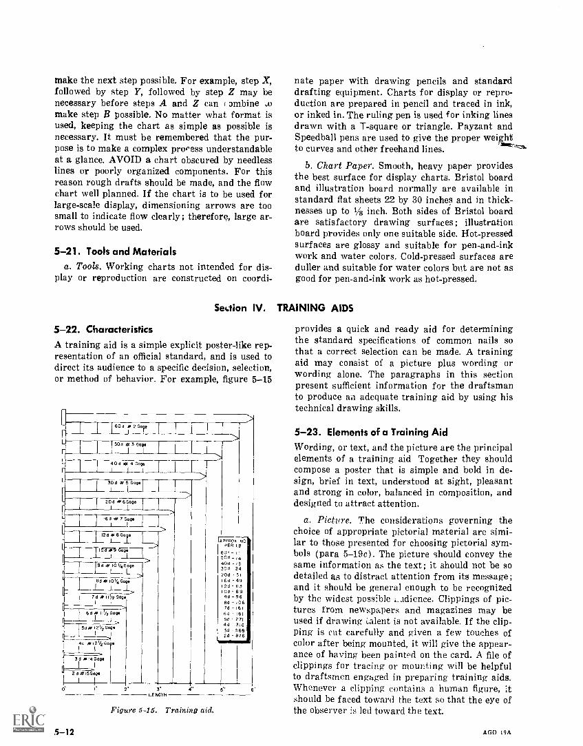
make the next step possible. For example, step X,followed by step Y, followed by step Z may benecessary before steps A and Z can ( ambine omake step B possible. No matter what format isused, keeping the chart as simple as possible isnecessary. It must be remembered that the pur-pose is to make a complex process understandableat a glance. AVOID a chart obscured by needlesslines or poorly organized components. For thisreason rough drafts should be made, and the flowchart well planned. If the chart is to be used forlarge-scale display, dimensioning arrows are toosmall to indicate flow clearly; therefore, large ar-rows should be used.
5-21. Tools and Materialsa. Tools. Working charts not intended for dis-
play or reproduction are constructed on coordi-
Section IV.
5-22. CharacteristicsA training aid is a simple explicit poster-like rep-resentation of an official standard, and is used todirect its audience to a specific decision, selection,or method of behavior. For example, figure 5-15
60° 7227
50e # 3 GageI 1
40 e # 4 GageI I
30d N 5 Gage
20d 446Gage
U 16d # 7 GageI 1
120 *14 8Gcle
10d 4,9 Gage
5-12
3'LENGTH
APPROX NOPER LB
60d- 1150d _14
40d - 1830d -24204 31
16d - 49
12d 63104 699d - 96
ed 1067d 161
6d 181
5d 2714d 3163d 5682d 816
Figure 5-15. Training aid.
nate paper with drawing pencils and standarddrafting equipment. Charts for display or repro-duction are prepared in pencil and traced in ink,or inked in. The ruling pen is used for inking linesdrawn with a T-square or triangle. Payzant andSpeedball pens are used to give the proper weightto curves and other freehand lines.
b. Chart Paper. Smooth, heavy paper providesthe best surface for display charts. Bristol boardand illustration board normally are available instandard flat sheets 22 by 30 inches and in thick-nesses up to 1/8 inch. Both sides of Bristol boardare satisfactory drawing surfaces ; illustrationboard provides only one suitable side. Hot-pressedsurfaces are glossy and suitable for pen-and-inkwork and water colors. Cold-pressed surfaces areduller and suitable for water colors but are not asgood for pen-and-ink work as hot-pressed.
TRAINING AIDS
provides a quick and ready aid for determiningthe standard specifications of common nails sothat a correct selection can be made. A trainingaid may consist of a picture plus wording orwording alone. The paragraphs in this sectionpresent sufficient information for the draftsmanto produce an adequate training aid by using histechnical drawing skills.
5-23. Elements of a Training Aid
Wording, or text, and the picture are the principalelements of a training aid Together they shouldcompose a poster that is simple and bold in de-sign, brief in text, understood at sight, pleasantand strong in color, balanced in composition, anddesigned to attract attention.
a. Picture. The considerations governing thechoice of appropriate pictorial material are simi-lar to those presented for choosing pictorial sym-bols (para 5-19c). The picture should convey thesame information as the text; it should not be sodetailed as to distract attention from its message ;and it should be general enough to be recognizedby the widest possible adience. Clippings of pic-tures from newspapers and magazines may beused if drawing Talent is not available. If the clip-ping is cut carefully and given a few touches ofcolor after being mounted, it will give the appear-ance of having been paint'd on the card. A file ofclippings for tracing or mounting will be helpfulto draftsmen engaged in preparing training aids.Whenever a clipping contains a human figure, itshould be faced toward the text so that the eye ofthe observer is led toward the text.
AGO 19A
b. Text. Text should be brief ; it should make acomplete statement ; and its meaning should beclear. When a training aid makes a series of state-ments, the number should not exceed four. Nega-tive statements should be avoided; the postershould tell what to do, rather than what not to do.When not expressed as a directive or command,the text should express a conclusive attitude.Wording is effective by virtue of its message andits mechanical arrangement on the poster.
5-24. LayoutThe layout of a poster is a rough pencil plan thatarranges lines, paragraphs, and pictures so thatthey have a pleasing relation to one another. Theimportant considerations in the layout of a posterare balance, harmony, unity, and simplicity.
a. Balance. The principle of balance is similarto that described in the layout of a pictorial chart.Lines of lettering and pictures are represented asrectangles and arranged symmetrically about ver-tical and horizontal centerlines or along intersect-ing diagonals drawn between opposite corners ofthe card. The lines of the rectangles parallel theborderlines of the poster. Balance also is affectedby tones. If one line of lettering is quite dark, itmust be balanced by an equal area of the sametone or a larger area of a lighter tone.
b. Harmony. Harmony implies a relationshipbetween the various layout rectangles. Size, shape,tone, and color must have qualities in commonthroughout.
c. Unity. The component parts of a training aidmust blend to focus audience attention on themost important units. This can be done by arrang-ing the most important parts of the inscription atthe most important points on the poster. Unre-lated statements should be avoided.
d. Simplicity. Training aids should not be over-ornamented. Letter styles, borders, and back-grounds should be simple enough to permit con-centration on the central message. Lettering isdrawn to the size required by good balance andemphasis.
e. Lettering. Letters are sketched in with a softpencil, and with guidelines to establish letterheight and inclination. If many posters are to bemade with the same size and style of lettering,templates can br; made by drawing the alphabetand numbers on a sheet of cardboard and cuttingthe letters out with a sharp knife and steelstraightedge. Beginners should construct blockletters of the kind shown in figure 4-4. The out-lines are drawn with a ruling pen after the letters
AGO 19A
have been sketched, and the open areas are filledin with a brush or ruling pen.
5-25. Use of ColorIndia inks are available in various colors. Drafts-men should limit themselves at first to two colorsin preparing training aids.
a. Color Combinations. Red is the most suitablesingle color for use in combination with black andwhite. It provides brightness and effective con-trast and its intensity permits the eye to focusreadily at normal reading distance. Black letter-ing against a yellow background provides the bestvisibility both for those with normal vision andfor those who are color blind. For this reason theblackandyellow combination is used on highwaysafety signs. Green against red, blue against red,and red against green should be avoided becausethese combinations seem to make the letters vi-brate and difficult to read.
b. Application of Colors. Poster color or inkmay be applied with a wide-point pen or a brush.If sufficiently diluted, poster color may be used inplace of ink to produce fine lines drawn with aruling pen. If a stencil is used for uniformity,letters may be cut out of colored paper and pastedon a poster with rubber cement or glue.
5-26. MaterialsIllustration and Bristol board are satisfactory forpreparing training aids.
a. Brushes. Brushes are made of sable orcamel's hair with the former preferable. They arein two styles, round and flat with square ends.The widths of the sizes most generally used rangefrom 1/4 to 1 inch. Brushes are used for letteringwith water colors.
(1) Use. A I s ush is held between the thumband the first two singers in a nearly vertical posi-tion and should not be gripped too tightly. Strokesare made with a full, swinging movement of thearm and with the extreme tip of the brush. Theflat brush should be kept well filled with color andshould b,.) lifted abruptly from the paper at theend of the stroke to give the stroke a square tip.Persistent practice is essential for the develop-ment of a satisfactory technique.
(2) Care. Brushes should always be keptclean and stored either flat or upright on the han-dle. To clean a brush, use the proper solvent orthinner for the color or colors used, to remove asmuch of the color as possible. Wet the brush inlukewarm water, apply a mild soap, and work upa lather by rubbing the brush on the palm of the
5-13
hand, then rinse it thoroughly. Reshape the brushand put it away.
b. Color. Prepared poster colors are available injars. Unless a particular color is used extensively,only the following colors need be on hand white,black, and the basic primary colors, red, yellow,and blue. To obtain the secondary colors combine,red and yellow to get orange, yellow and blue toget green, and blue and red to get purple. Whitecan be added to any of the above colors to getpinks, tints and light pastel colors. Black can beadded to the warm colors ( yJlow, red, and or-
5-14
ange) to obtain browns varying from raw umberto burnt sienna. Complimentary colors such as redand green can also be combined in equal amountsto produce a neutral brown. To obtain olive drab(O.D.) start with a quantity of green and addsmall amounts of red until the desired color isobtained. In some cases, due to the quality of pig-ment used in the paint, it may be necessary to adda touch of yellow or black or both to achieve thedesired color. There are also available special flu-orescent colors that glow, especially under ultravi-olet light, and can be used for special effects.
AGO 19A
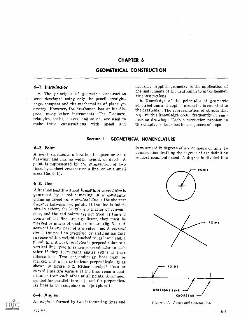
CHAPTER 6
GEOMETRICAL CONSTRUCTION
6-1. Introductiona. The principles of geometric construction
were developed using only the pencil, straight-edge, compass and the mathematics of plane ge-ometry. However, the draftsman has at his dis-posal many other instruments. The T-square,triangles, scales, curves, and so on, are used tomake these constructions with speed and
accuracy. Applied geometry is the application ofthe instruments of the draftsman to make geomet-ric constructions.
b. Knowledge of the principles of geometricconstructions and applied geometry is essential tothe draftsman. The representation of objects thatrequire this knowledge occur frequently in engi-neering drawings. Each construction problem inthis chapter is described by a sequence of steps.
Section I. GEOMETRICAL NOMENCLATURE
6-2. PointA point represents a location in space or on adrawing, and has no width, height, or depth. Apoint is represented by the intersection of twolines, by a short crossbar on a line, or by a smallcross (fig. 6-1).
6-3. LineA line has length without breadth. A curved line isgenerated by a point moving in a constantlychanging direction. A straight line is the shortestdistance between two points. If the line is indefi-nite in extent, the length is a matter of conveni-ence, and the end points are not fixed. If the endpoints of the line are significant, they must bemarked by means of small cross bars (fig. 6-1). Asegment is any part of a divided line. A verticalline is the position described by a string hangingin space with a weight attached to its lower end, aplumb line. A horizontal line is perpendicular to avertical line. Two lines are perpendicular to eachother if they form right angles (90°) at theirintersection. Two perpendicular lines may bemarked with a box to indicate perpendicularity asshown in figure 6-2. Either straig: 4. lines orcurved lines are parallel if the lines remain equi-distance from each other at all points. A commonsymbol for parallel lines is 11, and for perpendicu-lar lines is M (singular) or /H (plural).
6-4. AnglesAn angle is formed by two intersecting lines and
AGO 19A
is measured in degrees of arc or hours of time. Inconstruction drafting the degrees of arc definitionis most commonly used. A degree is divided into
POINT
POINT
POINT
STRAIGHT LINE
CROSSBAR
Figure 6-1. Points and straight line.
6-1
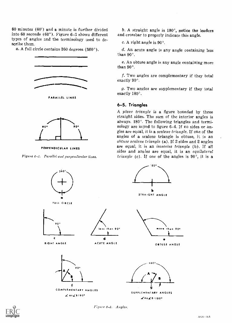
60 minutes (60') and a minute is further dividedinto 60 seconds (60"). Figure 6-3 shows differenttypes of angles and the terminology used to de-scribe them.
a. A full circle contains 360 degrees (360 °).
PARALLEL LINES
90° 90°
PERPENDICULAR LINES
Figure 6-2. Parallel and perpendicular lines.
360°
O
FULL CIRCLE
90°
C
RIGHT ANGLE
b. A straight angle is 180°, notice the leadersand crossbar to properly indicate this angle.
c. A right angle is 90°.
d. An acute angle is any angle containing lessthan 90°.
e. An obtuse angle is any angle containing morethan 90°.
f. Two angles are complementary if they totalexactly 90°.
g. Two angles are supplementary if they totalexactly 180°.
6-5. TrianglesA plane triangle is a figure bounded by threestraight sides. The sum of the interior angles isalways. 180 °. The following triangles and termi-nology are keyed to figure 6-4. If no sides or an-gles are equal, it is a scalene triangle. If one of theangles of a scalene triangle is obtuse, it is anobtuse scalene triangle (a). If 2 sides and 2 anglesare equal, it is an isosceles triangle (b). If allsides and angles are equal, it is an equilateraltriangle (c). If one of the angles is 90°, it is a
ACUTE ANGLE
COMPLEMENTARY ANGLES
de A+Zb=9o°
6-2
STRAPGHT ANGLE
motto than 60°
OBTUSE ANGLE
180°
Figu;-e Angles.
SUPPLEMENTARY ANGLES
LA },[ 8=180°
AGO 19A
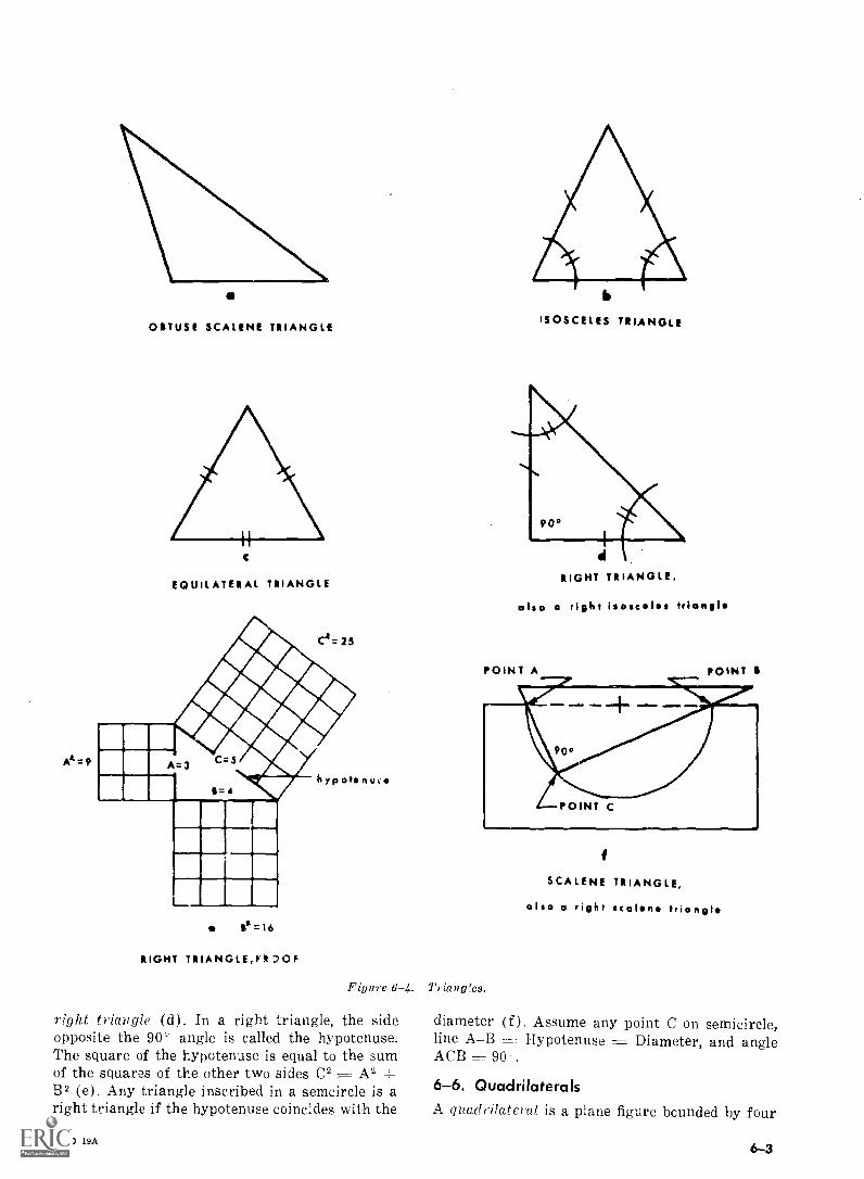
At =9
a
OITUSE SCALENE TRIANGLE
C
EQUILATERAL TRIANGLE
e=16
RIGHT TRIANGLEJE
Figure 6-4.
right triangle (d). In a right triangle, the sideopposite the 90' angle is called the hypotenuse.The square of the hypotenuse is equal to the sumof the squares of the other two sides C2 = A2 +B2 (e). Any triangle inscribed in a semcircle is aright triangle if the hypotenuse coincides with the
AGO 19A
ISOSCELES TRIANGLE
411
RIGHT TRIANGLE,
also a right isosceles triangle
POINT A POINT
SCALENE TRIANGLE,
also a right scaln triangt
Triaug!es.
diameter (f). Assume any point C on semicircle,line AB Hypotenuse = Diameter, and angleACB = 90-.
6-6. QuadrilateralsA quadrilateral is a plane figure bounded by four
6-3
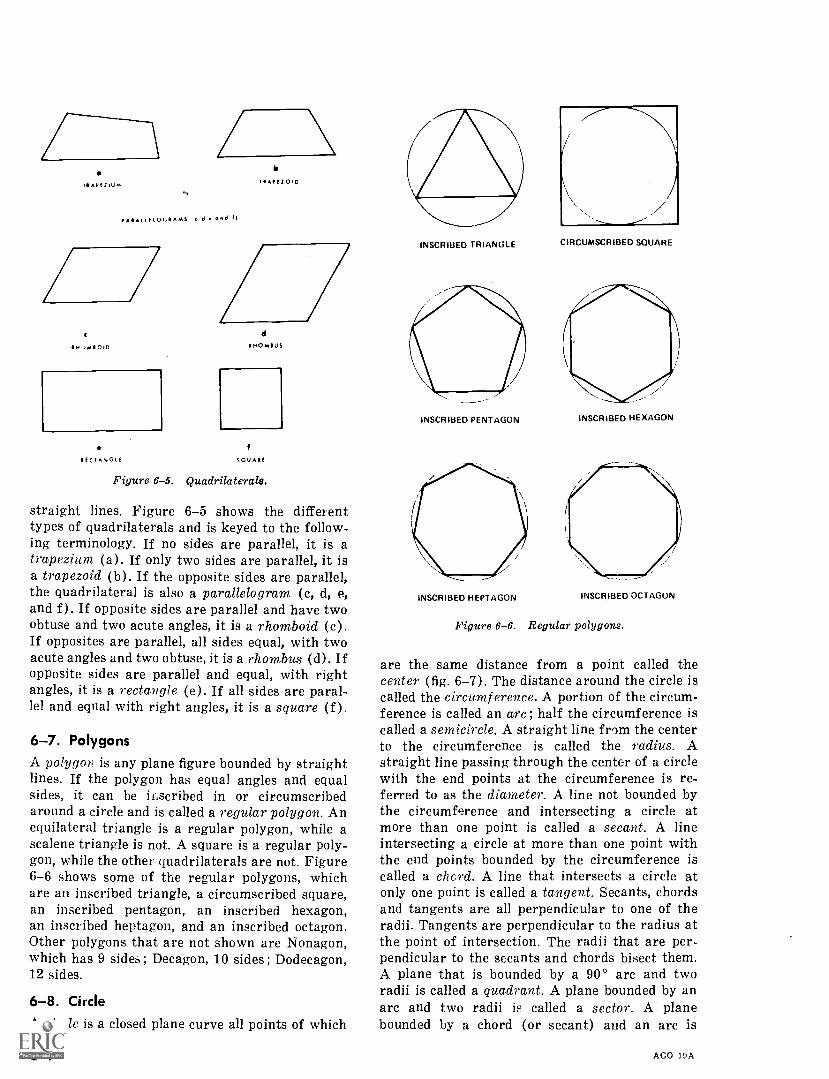
=DiI API /WM
C1711,,,m1101D
Ilf(IANGIf
bIPAPfZ0,13
c cl. and II
dIHOmIUS
cOUARI
Figure 6-5. Quadrilaterals.
straight lines. Figure 6-5 shows the differenttypes of quadrilaterals and is keyed to the follow-ing terminology. If no sides are parallel, it is atrapezium (a). If only two sides are parallel, it isa trapezoid (b). If the opposite sides are parallel,the quadrilateral is also a parallelogram (c, d,and f). If opposite sides are parallel and have twoobtuse and two acute angles, it is a rhomboid (c).If opposites are parallel, all sides equal, with twoacute angles and two obtuse, it is a rhombus (d). Ifopposite sides are parallel and equal, with rightangles, it is a rectangle (e). If all sides are paral-lel and equal with right angles, it is a square (f ).
6-7. PolygonsA polygon is any plane figure bounded by straightlines. If the polygon has equal angles and equalsides, it can be inscribed in or circumscribedaround a circle and is called a regular polygon. Anequilateral triangle is a regular polygon, while ascalene triangle is not. A square is a regular poly-gon, while the other quadrilaterals are not. Figure6-6 shows some of the regular polygons, whichare an inscribed triangle, a circumscribed square,an inscribed pentagon, an inscribed hexagon,an inscribed heptagon, and an inscribed octagon.Other polygons that are not shown are Nonagon,which has 9 sides ; Decagon, 10 sides ; Dodecagon,12 sides.
6-8. CircleA circle is a closed plane curve all points of which
INSCRIBED TRIANGLE
INSCRIBED PENTAGON
INSCRIBED HEPTAGON
CIRCUMSCRIBED SQUARE
INSCRIBED HEXAGON
INSCRIBED OCTAGON
Figure 6-6. Regular polygons.
are the same distance from a point called thecenter (fig. 6-7). The distance around the circle iscalled the circumference. A portion of the circum-ference is called an arc; half the circumference iscalled a semicircle. A straight line from the centerto the circumference is called the radius. Astraight line passing through the center of a circlewith the end points at the circumference is re-ferred to as the diameter. A line not bounded bythe circumference and intersecting a circle atmore than one point is called a secant. A lineintersecting a circle at more than one point withthe end points bounded by the circumference iscalled a chcrd. A line that intersects a circle atonly one point is called a tangent. Secants, chordsand tangents are all perpendicular to one of theradii. Tangents are perpendicular to the radius atthe point of intersection. The radii that are per-pendicular to the secants and chords bisect them.A plane that is bounded by a 90° arc and tworadii is called a quadrant. A plane bounded by anarc and two radii is called a sector. A planebounded by a chord (or secant) and an arc is
AGO 19A
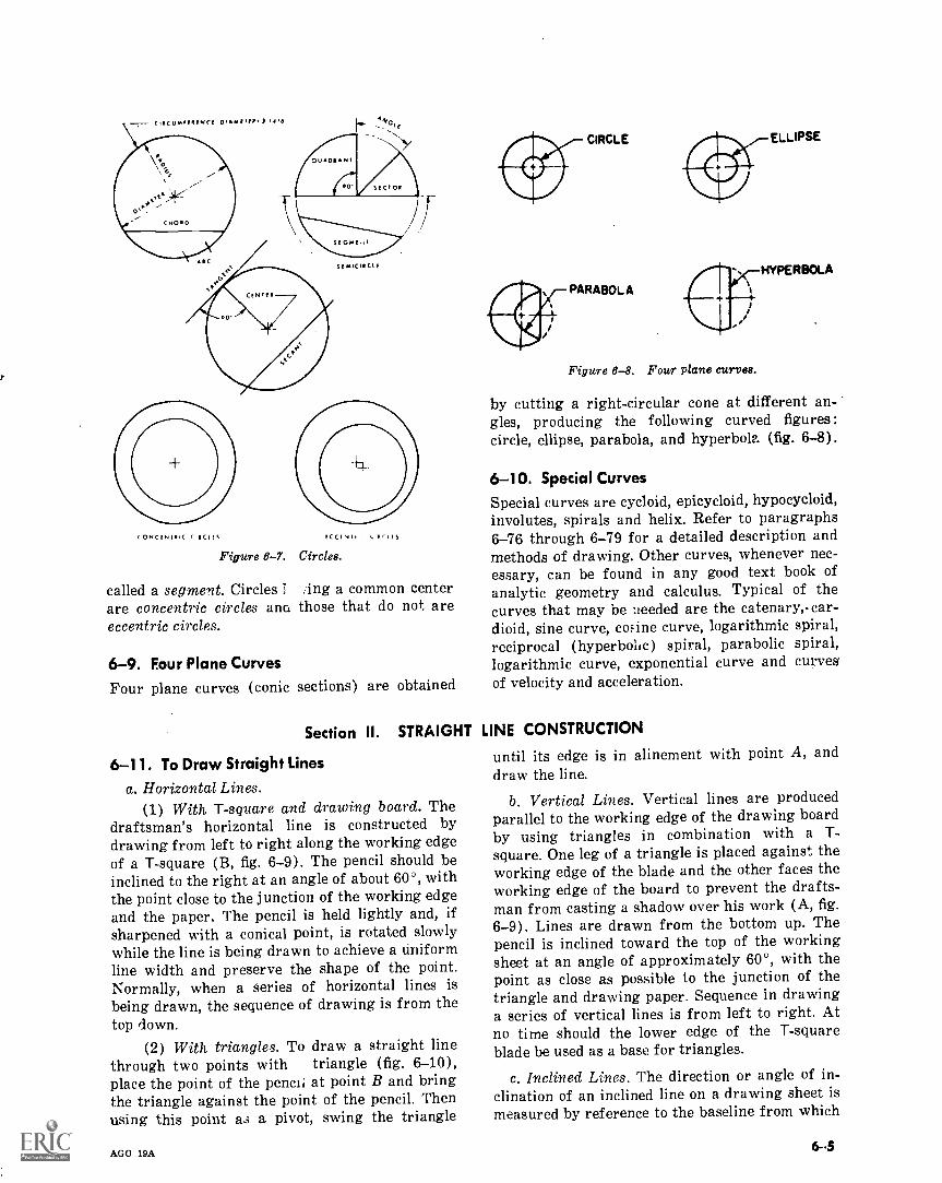
CONCINT*.( CI.CI FS
Figure 6-7.
called a segment. Circles 3are concentric circles anaeccentric circles.
6-9. Four Plane Curves
Four plane curves (conic
ECCI 1,115
Circles.
ing a common centerthose that do not are
sections) are obtained
Section II. STRAIGHT
6-11. To Draw Straight Linesa. Horizontal Lines.
(1) With T-square and drawing board. Thedraftsman's horizontal line is constructed bydrawing from left to right along the working edgeof a T-square (B, fig. 6-9). The pencil should beinclined to the right at an angle of about 60°, withthe point close to the junction of the working edgeand the paper. The pencil is held lightly and, ifsharpened with a conical point, is rotated slowlywhile the line is being drawn to achieve a uniformline width and preserve the shape of the point.Normally, when a series of horizontal lines isbeing drawn, the sequence of drawing is from thetop down.
(2) With triangles. To draw a straight linethrough two points with triangle (fig. 6-10),place the point of the pencil at point B and bringthe triangle against the point of the pencil. Thenusing this point a3 a pivot, swing the triangle
AGO 19A
CIRCLE
PARABOLA
Figure 6-8. Four plane curves.
ELLIPSE
HYPERBOLA
by cutting a right-circular cone at different an-gles, producing the following curved figures:circle, ellipse, parabola, and hyperbola (fig. 6-8).
6-10. Special CurvesSpecial curves are cycloid, epicycloid, hypocycloid,involutes, spirals and helix. Refer to paragraphs6-76 through 6-79 for a detailed description andmethods of drawing. Other curves, whenever nec-essary, can be found in any good text book ofanalytic geometry and calculus. Typical of thecurves that may be needed are the catenary, car-dioid, sine curve, cosine curve, logarithmic spiral,reciprocal (hyperbolic) spiral, parabolic spiral,logarithmic curve, exponential curve and curvesof velocity and acceleration.
LINE CONSTRUCTION
until its edge is in alinement with point A, anddraw the line.
b. Vertical Lines. Vertical lines are producedparallel to the working edge of the drawing boardby using triangles in combination with a T-square. One leg of a triangle is placed against theworking edge of the blade and the other faces theworking edge of the board to prevent the drafts-man from casting a shadow over his work (A, fig.6-9). Lines are drawn from the bottom up. Thepencil is inclined toward the top of the workingsheet at an angle of approximately 60°, with thepoint as close as possible to the junction of thetriangle and drawing paper. Sequence in drawinga series of vertical lines is from left to right. Atno time should the lower edge of the T-squareblade be used as a base for triangles.
c. Inclined Lines. The direction or angle of in-clination of an inclined line on a drawing sheet ismeasured by reference to the baseline from which
6-5
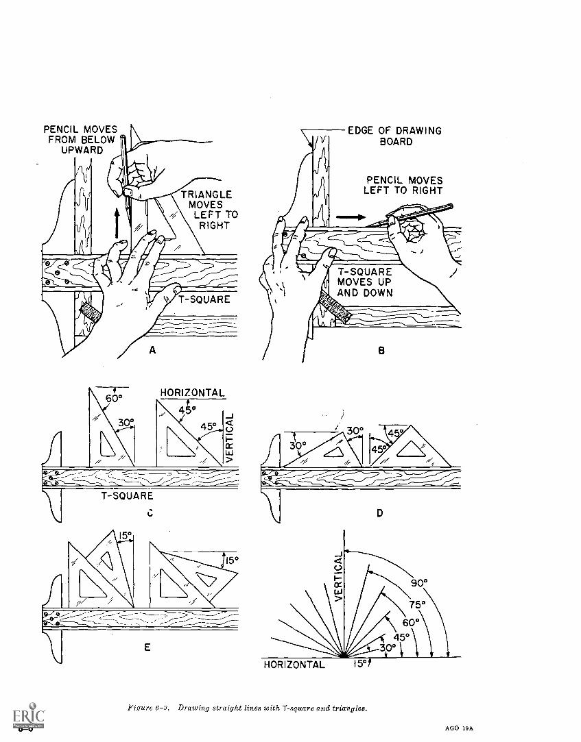
PENCIL MOVESFROM BELOW
UPWARD
TRIANGLEMOVESLEFT TO
RIGHT
T-SQUARE
60°
7/3
it
HORIZONTAL
45°45°
T-SQUARE
tJ
EDGE OF DRAWINGBOARD
PENCIL MOVESLEFT TO RIGHT
T-SQUAREMOVES UPAND DOWN
30°21°
30
B
4
45//
D
HORIZONTAL
Figure 6-9. Drawing straight lines with T- square and triangles.
6-6 AGO 19A
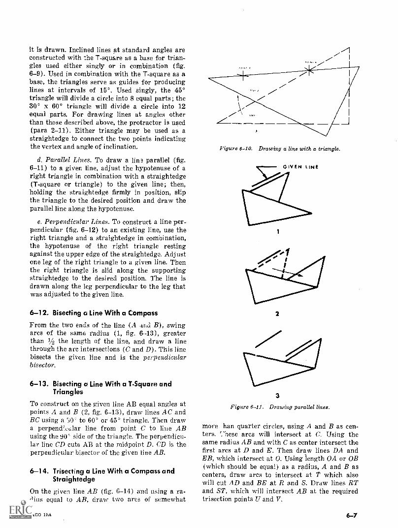
it is drawn. Inclined lines at standard angles areconstructed with the T-square as a base for trian-gles used either singly or in combination (fig.6-9). Used in combination with the T-square as abase, the triangles serve as guides for producinglines at intervals of 15°. Used singly, the 45°triangle will divide a circle into 8 equal parts; the30° x 60° triangle will divide a circle into 12equal parts. For drawing lines at angles otherthan those described above, the protractor is used(para 2-11). Either triangle may be used as astraightedge to connect the two points indicatingthe vertex and angle of inclination.
d. Parallel Lines. To draw a lin3 parallel (fig.6-11) to a given line, adjust the hypotenuse of aright triangle in combination with a straightedge(T-square or triangle) to the given line; then,holding the straightedge firmly in position, slipthe triangle to the desired position and draw theparallel line along the hypotenuse.
e. Perpendicular Lines. To construct a line per-pendicular (fig. 6-12) to an existing line, use theright triangle and a straightedge in combination,the hypotenuse of the right triangle restingagainst the upper edge of the straightedge. Adjustone leg of the right triangle to a given line. Thenthe right triangle is slid along the supportingstraightedge to the desired position. The line isdrawn along the leg perpendicular to the leg thatwas adjusted to the given line.
6-12. Bisecting a Line With a Compass
From the two ends of the line (A and B), swingarcs of the same radius (1, fig. 6 - -13), greaterthan 1A the length of the line, and draw a linethrough the arc intersections (C and D). This linebisects the given line and is the perpendicularbisector.
6-13. Bisecting a Line With a T-Square andIrking les
To construct on the given line AB equal angles atpoints A and B (2, fig. 6-13), draw lines AC andBC using a SO' to 60° or 45° triangle. Then drawa perpencEetilar line from point. C to line ABusing the 900 side of the triangle. The perpendicu-lar line CD cuts AB at the midpoint D. CD is theperpendicular bisector of the given line AB.
6-14. Trisecting a Line With a Compass andStraightedge
On the given line AB (fig. 6-14) and using a ra-dius equal to AB, draw two arcs of somewhat
AGO 19A
A
Figure 6 -10. Drawing a line with a triangle.
GIVEN LINE
1
2
3
Figure 6-11. Drawing parallel lines.
more han quarter circles, using A and B as cen-ters. niese arcs will intersect at C. Using thesame radius AB and with C as center intersect thefirst arcs at D and E. Then draw lines DA andEB, which intersect at 0. Using length OA or OB(which should be equal) as a radius, A and B ascenters, draw arcs to intersect at T which alsowill cut AD and BE at R and S. Draw lines RTand ST, which will intersect AB at the requiredtrisection points U and V.
6-7
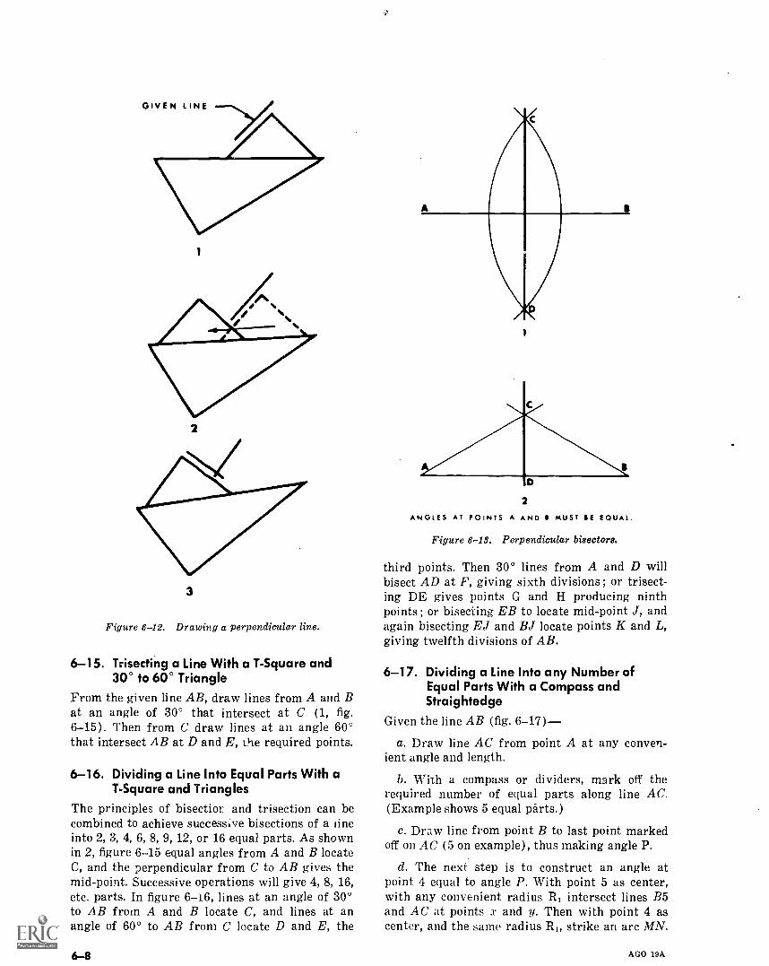
1
2
3
Figure 6-12. Drawing a perpendicular line.
6-15. Trisecting a Line With a T-Square and30° to 60° Triangle
From the given line AB, draw lines from A and Bat an angle of 30° that intersect at C (1, fig.6-15). Then from C draw lines at an angle 60°that intersect AB at D and E, the required points.
6-16. Dividing a Line Into Equal Parts With aT-Square and Triangles
The principles of bisectior and trisection can becombined to achieve successive bisections of a lineinto 2, 3, 4, 6, 8, 9, 12, or 16 equal parts. As shownin 2, figure 6-15 equal angles from A and B locateC, and the perpendicular from C to AB gives themid-point. Successive operations will give 4, 8, 16,etc. parts. In figure 6i6, lines at an angle of 30°to AB from A and B locate C, and lines at anangle of 60° to AB from C locate D and E, the
2
ANGLES AT POINTS A AND B MUST SE EQUAL.
Figure 6-13. Perpendicular bisectors.
third points. Then 30° lines from A and D willbisect AD at F, giving sixth divisions ; or trisect-ing DE gives points G and H producing ninthpoints ; or bisecting EB to locate mid-point J, andagain bisecting EJ and BJ locate points K and L,giving twelfth divisions of AB.
6-17. Dividing a Line Into any Number ofEqual Parts With a Compass andStraightedge
Given the line AB (fig. 6-17)
a. Draw line AC from point A at any conven-ient angle and length.
b. With a compass or dividers, mark off therequired number of equal parts along line AC.(Example shows 5 equal parts.)
c. Draw line from point B to last point markedoff on AC (5 on example), thus making angle P.
d. The next step is to construct an angle atpoint 4 equal to angle P. With point 5 as center,with any convenient radius R, intersect lines B5and AC at points x and y. Then with point 4 ascenter, and the same radius RI, strike an arc MN.
AGO 19A
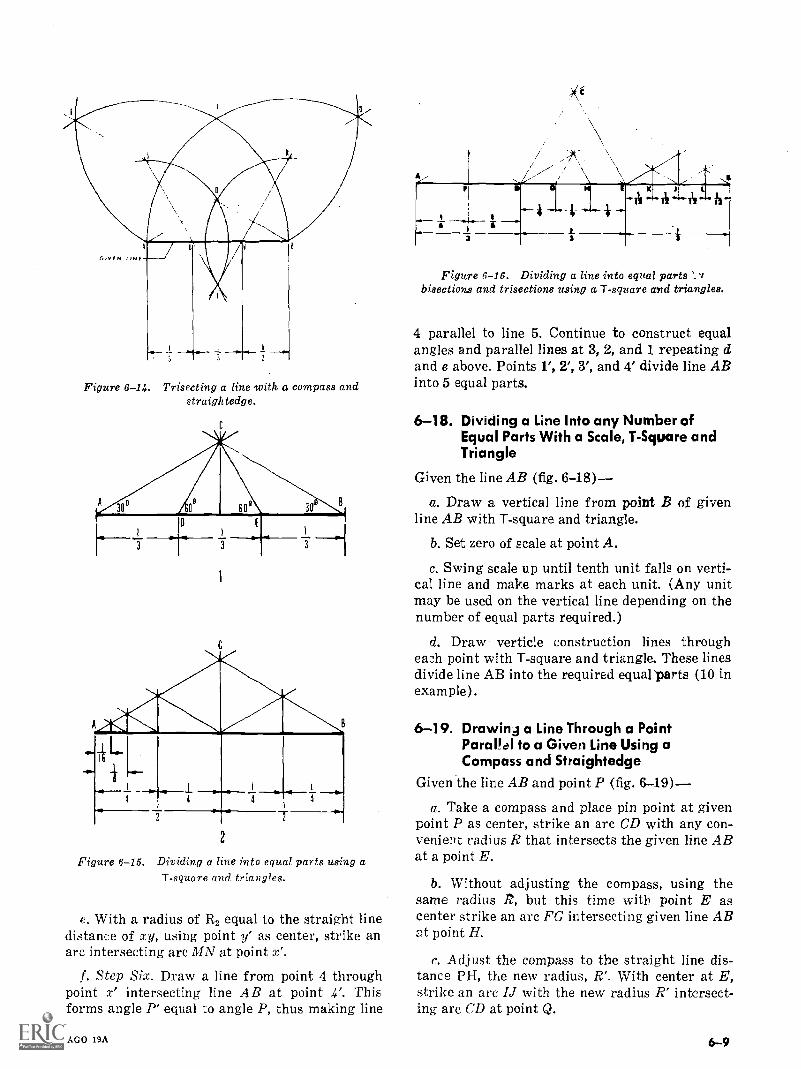
Figure 6-14. Trisecting a line with a compass andstraightedge.
Figure 6-15. Dividing a line into equal parts using aT-square and triangles.
e. With a radius of R, equal to the straight linedistance of xy, using point y' as center, strike anarc intersecting arc MN at point x'.
f. Step Six. Draw a line from point 4 throughpoint x' intersecting line AB at point 4'. Thisforms angle P' equal to angle P, thus making line
AGO 19A
3
Figure 6 -16.6-16. Dividing a line into equal partsbisections and trisections using a T-square and triangles.
4 parallel to line 5. Continue to construct equalangles and parallel lines at 3, 2, and 1 repeating dand e above. Points 1', 2', 3', and 4' divide line ABinto 5 equal parts.
6-18. Dividing a Line Into any Number ofEqual Parts With a Scale, T-Square andTriangle
Given the line AB (fig. 6-18)
a. Draw a vertical line from point B of givenline AB with T-square and triangle.
b. Set zero of scale at point A.
c. Swing scale up until tenth unit falls on verti-cal line and make marks at each unit. (Any unitmay be used on the vertical line depending on thenumber of equal parts required.)
d. Draw verticle construction lines througheach point with T-square and triangle. These linesdivide line AB into the required equal parts (10 inexample).
6-19. Drawinj a Line Through a PointParallel to a Given Line Using aCompass and Straightedge
Given the line AB and point P (fig. 6-19)
a. Take a compass and place pin point at givenpoint P as center, strike an arc CD with any con-venient radius R that intersects the given line ABat a point E.
b. Without adjusting the compass, using thesame radius R, but this time with point E ascenter strike an arc FG intersecting given line ABat point H.
c. Adjust the compass to the straight line dis-tance PH, the new radius, R'. With center at E,strike an arc IJ with the new radius R' intersect-ing arc CD at point Q.
6-9
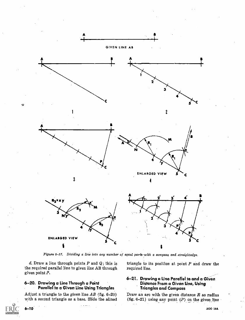
GIVEN LINE AB
2
3
ENLARGED VIEW
Figure 6-17. Dividing a line into any number
d. Draw a line through points P and Q; this isthe required parallel line to given line AB throughgiven point P.
6-20. Drawing a Line Through a PointParallel to a Given Line Using Triangles
Adjust a triangle to the given line AB (fig. 6-20)with a second triangle as a base. Slide the alined
6.-10
ENLARGED VIEW
4
of equal parts-with a compass and straightedge.
triangle to its position at point P and draw therequired line.
6-21. Drawing a Line Parallel to and a GivenDistance From a Given Line, UsingTriangles and Compass
Draw an arc with the given distance R as radius(fig. 6-21) using any point (P) on the given _line
AGO 19A
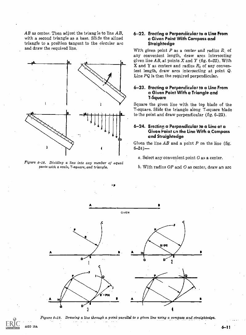
AB as center. Then adjust the triangle to line AB,with a second triangle as a base. Slide the alinedtriangle to a position tangent to the circular arcand draw the required line.
1
Figure 6-18. Dividing a line into any number of equaolparts with a scale, T-square, and triangle.
p
A=110
xi
6-22. Erecting a Perpendicular to a Line Froma Given Point With Compass andStraightedge
With given point P as a center and radius R1 ofany convenient length, draw arcs intersectinggiven line AB, at points X and Y (fig. 6-22). WithX and Y as centers and radius ./22 of any conven-ient length, draw arcs intersecting at point Q.Line PQ is then the required perpendicular.
6-23. Erecting a Perpendicular to a Line Froma Given Point With a Triangle and1-Square
Square the given line with the top blade of theT-square. Slide the triangle along T-square bladeto the point and draw perpendicular (fig. 6-23).
6-24. Ere:tins a Perpendicular to a Line at aGiven Point cn the Line With a Compassand Straightedge
Given the line AB and a point P on the line (fig.6-24)--
a. Select any convenient point 0 as a center.
b. With radius OP and 0 as center, draw an arc
GIVEN
It' = PH I
Pigure
AGO 19A
3
Drawing a line through a point parallel to a. given line using a compass and straightedge.
6-11
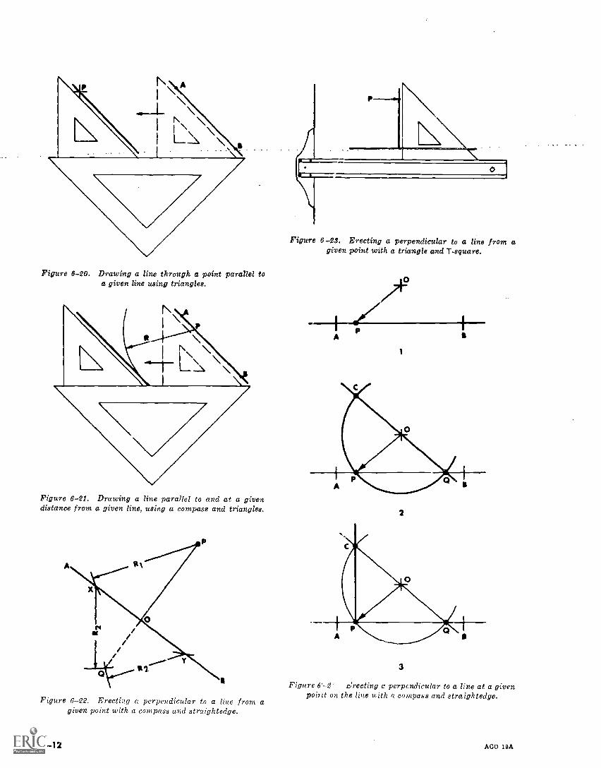
Figure 6-20. Drawing a line through a pointa given line using triangles.
parallel to
Figure 6-21. Drawing a line parallel to and at a givendistance from a given line, using a compass and triangles.
Figure 6-22. Erecting a perpendicular to a line from agiven point with a compass and straightedge.
6-12
Figure 6 23. Erecting a perpendicular to a line from agiven point with a triangle and T-square.
--I-- I/A
/12
1
2
3
Figure 6'---2' Zrecting r perpcndicular to a line at a givenpoint on the line with a compass and straightedge.
AGO 19A
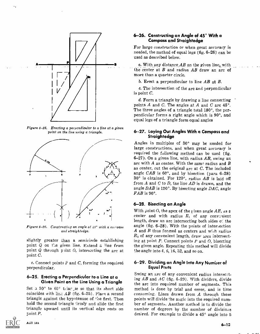
Figure 6-25. Erecting a perpendicular to a line at a givenpoint on the line using a triangle.
4
Figure 6-26. Constructing an angle of 45° with a col ,roassand straightedge.
slightly greater than a semicircle establishingpoint Q on tlie given line. Extend a line frompoint Q through pint 0, intersecting the arc atpoint C.
c. Connect points P and C, forming the requiredperpendicular.
6-25. Erecting a Perpendicular to a Line at aGiven Point on the Line Using a Triangle
Set a 30° to 60° tl iar ,le so that its short sidecoincides with linc AB (fig. 6-25). Place a secondtriangle against the hypotenuse of the first. Thenhold the second triangle 'irmly and slide the firsttriangle upward until its vertical edge rests onpoint P.
AGO 19A
6-26. Constructing an Angle of 45° With aCompass and Straightedge
For large construction or when great accuracy isneeded, the method of equal legs (fig. 6-26) can beused as described below.
a. With any distance AB on the given linen withthe center at B and radius AB draw an arc ofmore than a quarter circle.
b. Erect a perpendicular to line AB at B.c. The intersection of the are and perpendicular
is point C.
d. Form a triangle by drawing a line connectingpoints A and C. The angles at A and C are 45°.The three angles of a triangle total 180°, the per-pendicular forms a right angle which is 90°, andequal legs of a triangle form equal angles
6-27. Laying Out Angles With a Compass andStraightedge
Angles in multiples of 30° may be needed forlarge constructions, and when great accuracy isrequired the following method can be used (fig.6-27). On a given line, with radius AB, swing anarc with A as center. With the same radius and Bas center, cut the original arc at C. The includedangle CAB is 60°, and by bisection (para 6-28)30° is obtained. For 120°, radius AB is laid offfrom A and C to D, the line AD is drawn, and theangle DAB is 120°. By bisecting angle DAC, angleFAB is 90°.
6-28. Bisecting an AngleWith point 0, the apex of the given angle AB, as acenter and with radius R, of any convenientlength, draw an arc intersecting both sides o': theangle (fig. 6-28). With the points of intersectionA and B thus formed as centers and with radiusR2 of any convenient length, draw arcs intersect-ing at point P. Connect points P and 0, bisectingthe given angle. Repeating this method will dividethe angle into 4,8,16,52, and so on.
6-29. Dividing an Angle Into Any Number ofEqual Ports
Swing an, arc of any convenient radius intersect-ing AB and AC (fig. 6-29). With dividers, dividethe arc into required number of segments. Thismethod is done by trial and error, and is timeconsuming. Lines drawn from A through thesepoints will divide the aligle into the required num-ber of segments. Another method is to divide thenumber of degrees by the number of divisionsdesired. For example to divide a 45° angle into 5
6 -13
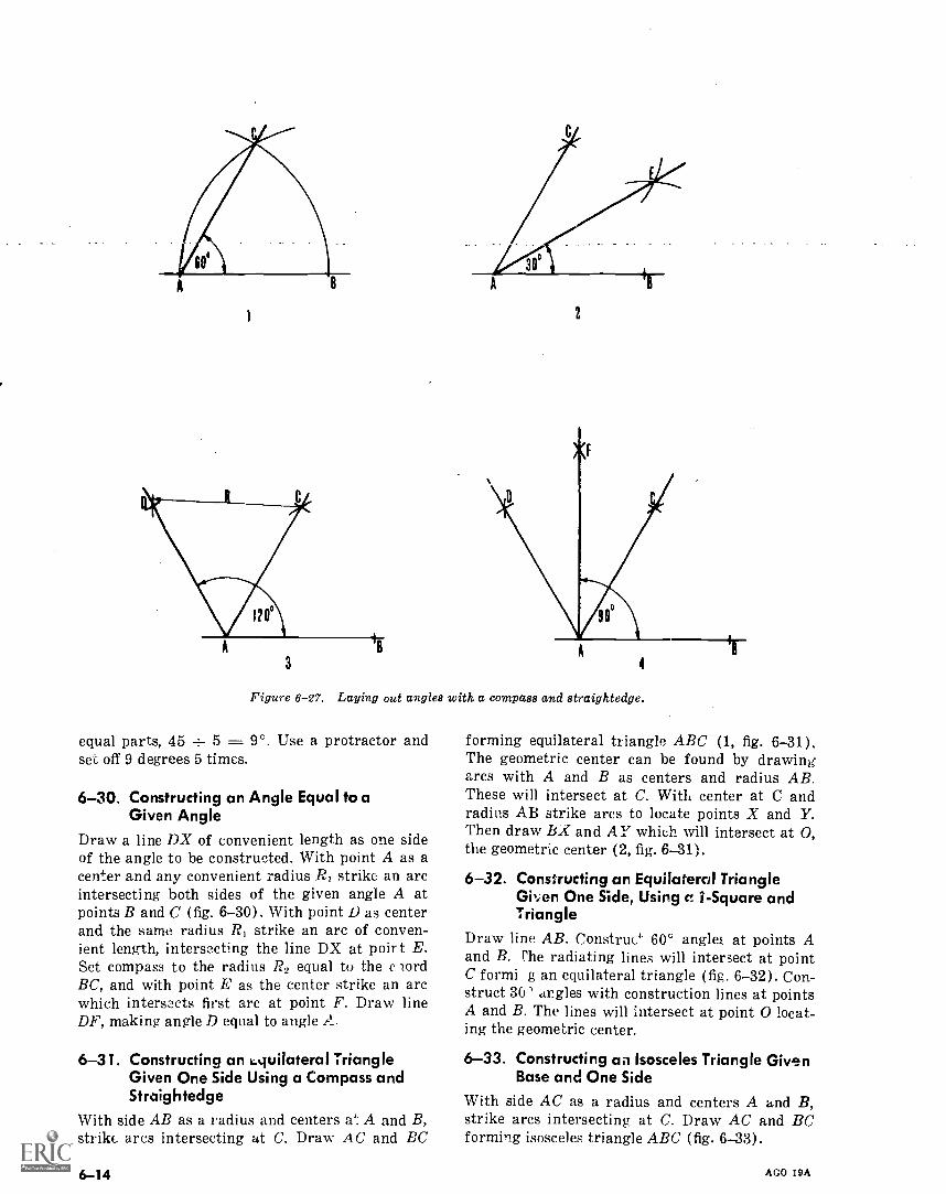
1
3
2
Figure 6-27. Laying out angles with a compass and straightedge.
equal parts, 45 ± 5 = 9°. Use a protractor andset off 9 degrees 5 times.
6-30. Constructing an Angle Equal to aGiven Angle
Draw a line DX of convenient length as one sideof the angle to be constructed. With point A as acenter and any convenient radius RI strike an arcintersecting both sides of the given angle A atpoints B and C (fig. 6-30). With point L) as centerand the same radius R, strike an arc of conven-ient length, intersecting the line DX at poirt E.Set compass to the radius R2 equal to the c lordBC, and with point E as the center strike an arcwhich intersects first arc at point F. Draw lineDIP, making angle D equal to angle 2-1
6-31. Constructing an 1,.quilateral TriangleGiven One Side Using a Compass andStraightedge
With side AB as a radius and centers at A and B,
strike, arcs intersecting at C. Draw AC and EC
6-14
forming equilateral triangle ABC (1, fig.6-31).The geometric center can be found by drawingarcs with A and B as centers and radius AB.These will intersect at C. With center at C andradius AB strike arcs to locate points X and Y.Then draw BX and AY which will intersect at 0,the geometric center (2, fig. 6-31).
6-32. Constructing an Equilateral TriangleGi,,en One Side, Using c 1- Square andTriangle
Draw line AB. Construe.` 60° angleE at points Aand B. ¶'he radiating lines will intersect at pointC formi g an equilateral triangle (fig. 6-32). Con-struct 30' angles with construction lines at pointsA and B. The lines will intersect at point 0 locat-ing the geometric center.
6-33. Constructing an Isosceles Triangle GivenBase and One Side
With side AC as a radius and centers A and B,
strike arcs intersecting at C. Draw AC and BCforming isosceles triangle ABC (fig. 6-33).
AGO 19A
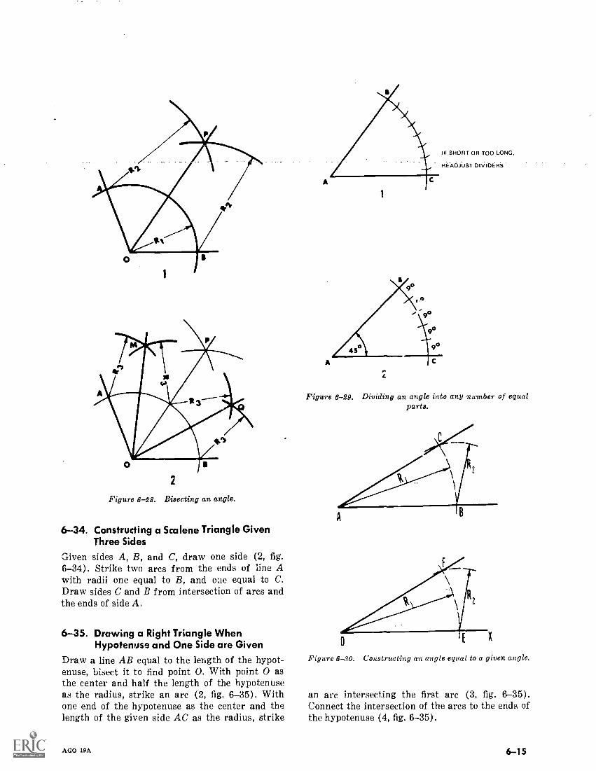
2
Figure 6-28. Bisecting an angle.
6-34. Constructing a Scalene Triangle GivenThree Sides
Given sides A, B, and C, draw one side (2, fig.6-34). Strike two arcs from the ends of line Awith radii one equal to B, and one equal to C.Draw sides C and B from intersection of arcs andthe ends of side A.
6-35. Drawing a Right Triangle WhenHypotenuse and One Side are Given
Draw a line AB equal to the length of the hypot-enuse, bisect it to find point 0. With point 0 asthe center and half the length of the hypotenuseas the radius, strike an arc (2, fig. 6-35). Withone end of the hypotenuse as the center and thelength of the given side AC as the radius, strike
AGO 19A
1
Si.
IF SHORT OR TOO LONG,
READJUST DIVIDERS
Figure 6-29. Dividing an angle into any number of equalparts.
X
Figure 6-30. Constructing an angle equal to a given angle.
an arc intersecting the first arc (3, fig. 6-35).Connect the intersection of the arcs to the ends ofthe hypotenuse (4, fig. 6-35).
6-15
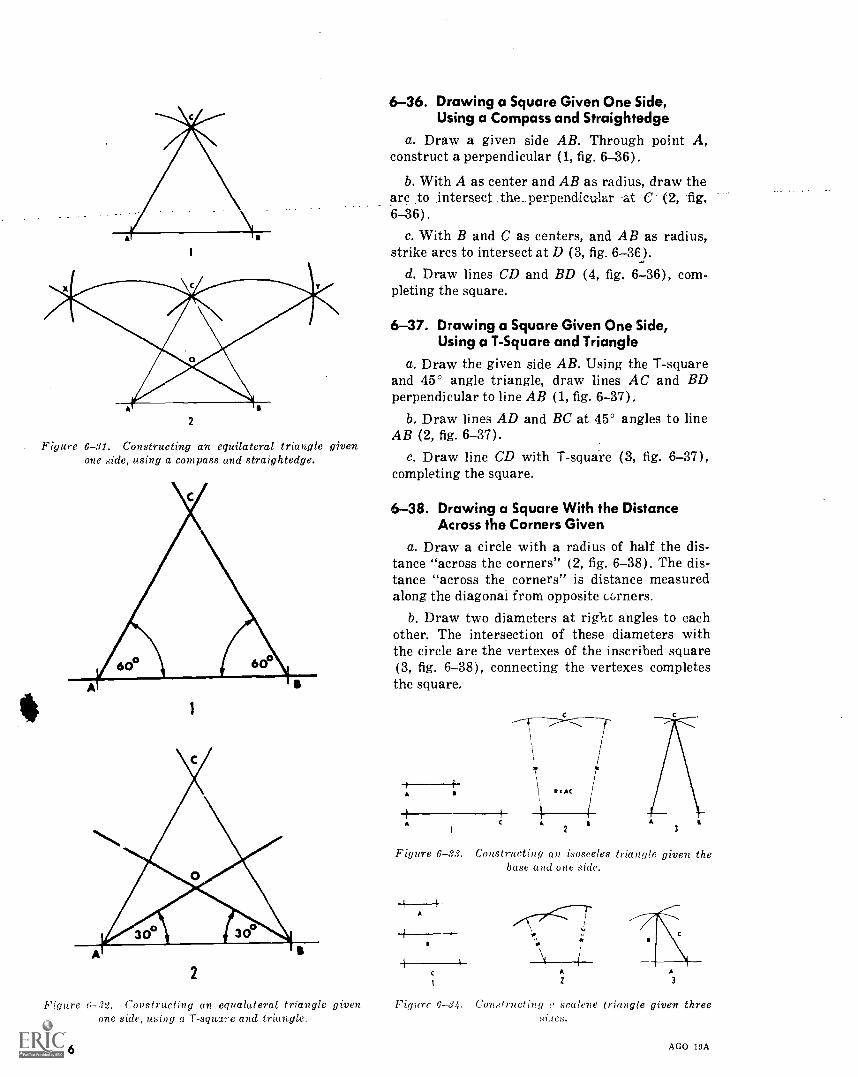
2
Figure 6-31. Constructing an equilateral triangle givenone side, using a compass and straightedge.
2
6-36. Drawing a Square Given One Side,Using a Compass and Straightedge
a. Draw a given side AB. Through point A,construct a perpendicular (1, fig. 6-36).
b. With A as center and AB as radius, draw thearc to intersect the_ perpendicular at C- (2, fig.6-36).
c. With B and C as centers, and AB as radius,strike arcs to intersect at D (3, fig. 6-3E).
d. Draw lines CD and BD (4, fig. 6-36), com-pleting the square.
6-37. Drawing a Square Given One Side,Using a T-Square and Triangle
a. Draw the given side AB. Using the T-squareand 45° angle triangle, draw lines AC and BDperpendicular to line AB (1, fig. 6-37).
b. Draw lines AD and BC at 45° angles to lineAB (2, fig. 6-37).
c. Draw line CD with T-square (3, fig. 6-37),completing the square.
6-38. Drawing a Square With the DistanceAcross the Corners Given
a. Draw a circle with a radius of half the dis-tance "across the corners" (2, fig. 6-38). The dis-tance "across the corners" is distance measuredalong the diagonal from opposite curlers.
b. Draw two diameters at right angles to eachother. The intersection of these diameters withthe circle are the vertexes of the inscribed square(3, fig. 6-38), connecting the vertexes completesthe square.
A
A C 0,
2
AC
3
Figure 6-33. Constructing an 'isosceles triangle given thebase and one side.
4
A
1 i
s
4 4\ 1
c A
12
Figure 6-32. Constructing an egualateral triangle given Figure 6-34. Constructing o scalene triangle given threeone side, using a T- square and triangle.
6-16
.1C S.
AGO 19A
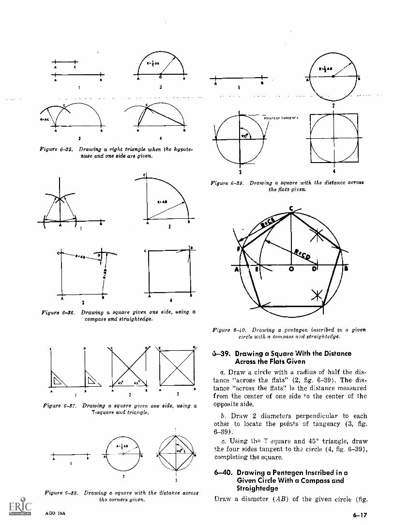
A
a
3
2
4
Figure 6-45. Drawing a right triangle when the hypote-nuse and one side are given.
s
A
3
Figure 6-46. Drawing a square given one side, using acompass and straightedge.
2
A4
Figure 6-37. Drawing a square given one side, using aT-square and triangle.
A
23
Figure 6-38. Drawing a square with the distance acrossthe corners given.
AGO 19A
A
POINTS OF TANGE NC Y
3 4
Figure 6-49. Drawing a square with the distance acrossthe flats given.
Figure 6-40. Drawing a pentagon inscribed in a givencircle with a compass and straightedge.
6-39. Drawing a Square With the DistanceAcross the Flats Given
a. Draw a circle with a radius of half the dis-tance "across the flats" (2, fig. 6-39). The dis-tance "across the flats" is the distance measuredfrom the center of one side to the center of theopposite side.
b. Draw 2 diameters perpendicular to eachother to locate the points of tangency (3, fig.6-39).
c. Using the T square and 45° triangle, drawthe four sides tangent to tha circle (4, fig. 6-39),completing the square.
6-40. Drawing a Pentagon Inscribed in aGiven Circle With a Compass andStraightedge
Draw a diameter (AB) of the given circle (fig.
6-17
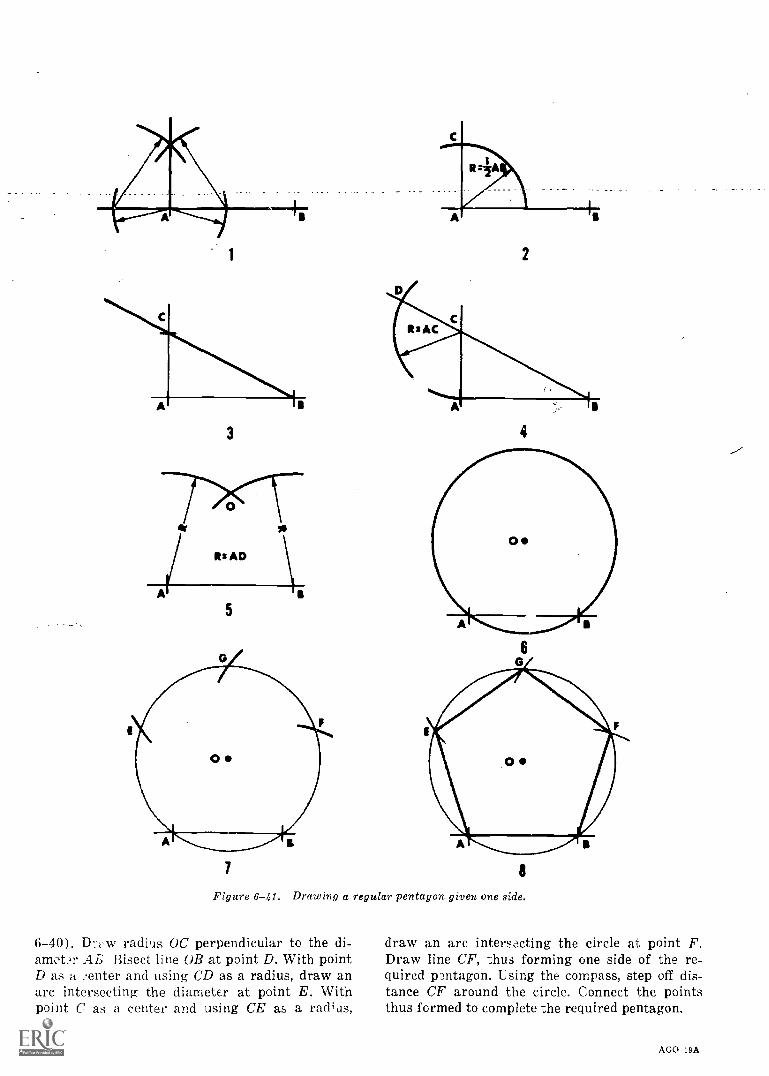
3
5
7
2
4
8
Figure 6-41. Drawing a regular pentagon given one side.
6-40). DI-Ny radils OC perpendicular to the di-a.motr Ai; Bisect line OB at point D. With pointD as a center and using CD as a radius, draw anarc intersecting the diameter at point E. Withpoint C as a center and using CE as a radius,
6-78
draw an arc intersecting the circle at point F.Draw line CF, thus forming one side of the re-quired pentagon. Lsing the compass, step off dis-tance CF around the circle. Connect the pointsthus formed to complete the required pentagon.
AGO 19A
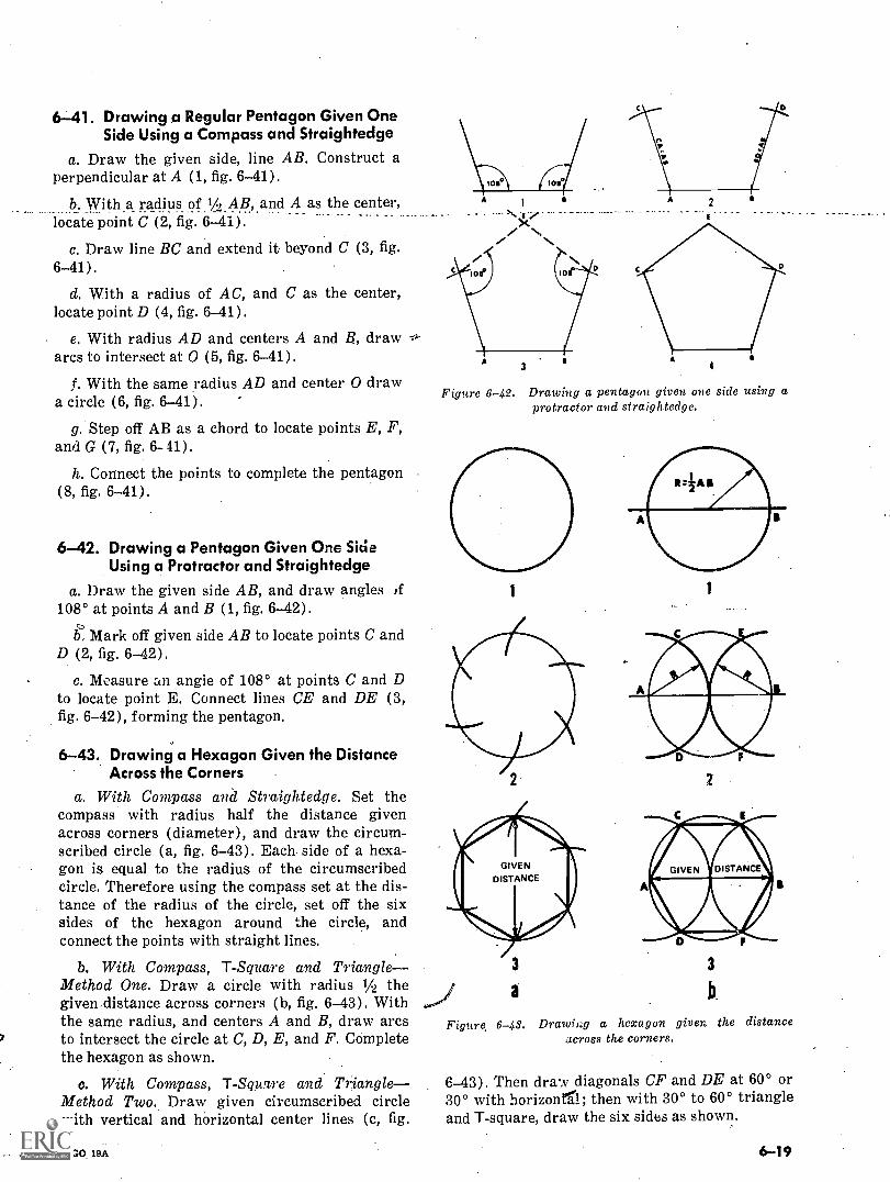
6-41. Drawing a Regular Pentagon Given OneSide Using a Compass and Straightedge
a. Draw the given side, line AB. Construct aperpendicular at A (1, fig. 6-41).
b. With.a radius of .1/2_AB,_and A as the center,locate point C (2, fig. 6-41).
c. Draw line BC and extend it beyond C (3, fig.
6-41).
d. With a radius of AC, and C as the center,locate point D (4, fig. 6-41).
e. With radius AD and centers A and B, drawarcs to intersect at 0 (5, fig. 6-41).
1. With the same radius AD and center 0 drawa circle (6, fig. 6-41).
g. Step off AB as a chord to locate points E, F,and G (7, fig. 6-41).
h. Connect the points to complete the pentagon(8, fig. 6-41).
6-42. Drawing a Pentagon Given One SideUsing a Protractor and Straightedge
a. Draw the given side AB, and draw angles ,f108° at points A and B (1, fig. 6-42).
k Mark off given side AB to locate points C andD (2, fig. 6-42).
c. Measure an angle of 108° at points C and Dto locate point E. Connect lines CE and DE (3,fig. 6-42), forming the pentagon.
6-43. Drawing a Hexagon Given the DistanceAcross the Corners
a. With Compass and Straightedge. Set thecompass with radius half the distance givenacross corners (diameter), and draw the circum-scribed circle (a, fig. 6-43). Each side of a hexa-gon is equal to the radius of the circumscribedcircle. Therefore using the compass set at the dis-tance of the radius of the circle, set off the sixsides of the hexagon around the circle, andconnect the points with straight lines.
b. With Compass, T- Square and Triangle- -Method One. Draw a circle with radius 1/4 thegiven distance across corners (b, fig. 6-43). Withthe same radius, and centers A and B, draw arcsto intersect the circle at C, D, E, and F. Completethe hexagon as shown.
c. With Compass, T-Square and TriangleMethod Two. Draw given circumscribed circlewith vertical and horizontal center lines (c, fig.
AGO 19A
/
3
Figure 6-42. Drawing a pentagon given one side using aprotractor and straightedge.
a
2
3
b.
Figure, 6-43. Drawiag a hexagon given the distanceacross the corners.
6-43). Then draw diagonals CF and DE at 60° or30° with horizon11; then with 30° to 60° triangleand T-square, draw the six sides as shown,
6-19
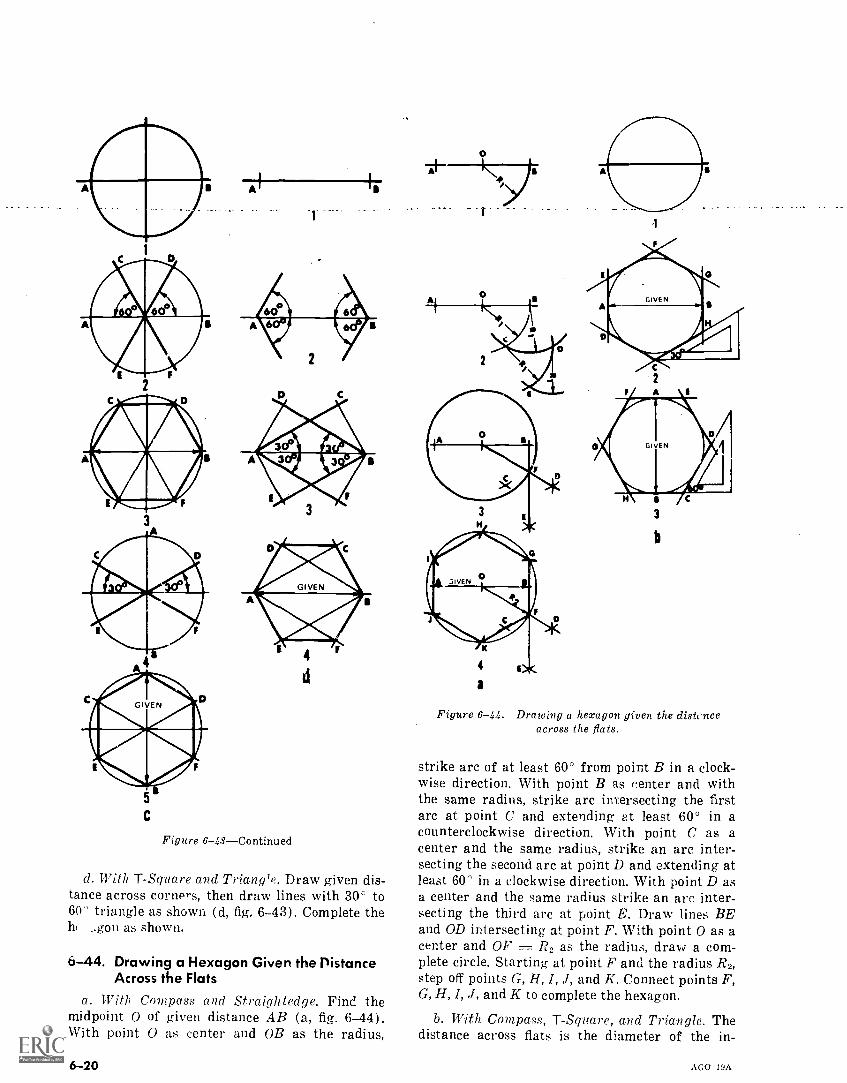
C
Figure 6-43Continued
d. With T-Square and Triangle. Draw given dis-tance across corners, then draw lines with 30° to60' triangle as shown (d, fig. 6-43). Complete theh. _,gon as shown.
6-44. Drawing a Hexagon Given the DistanceAcross the Flats
a. With Compass and Straightedge. Find themidpoint 0 of given distance AB (a, fig. 6-44).With point 0 as center and OB as the radius,
6 -20
a
2
3
b
Figure 6-44. Drawing a hexagon given the distcnceacross the fiats.
strike arc of at least 60° from point B in a clock-wise direction. With point B as center and withthe same radius, strike arc intersecting the firstarc at point C and extending at least 60° in acounterclockwise direction. With point C as acenter and the same radius, strike an arc inter-secting the second arc at point D and extending atleast 60° in a clockwise direction. With point D asa center and the same radius strike an arc inter-secting the third arc at point E. Draw lines BEand OD intersecting at point F. With point 0 as acenter and OF as the radius, draw a com-plete circle. Starting at point F and the radius R2,step off points G, H, I, J, and K. Connect points F,G, H, I, J, and K to complete the hexagon.
b. With Compass, T-Square, and Triangle. Thedistance across flats is the diameter of the in-
AGO 19A
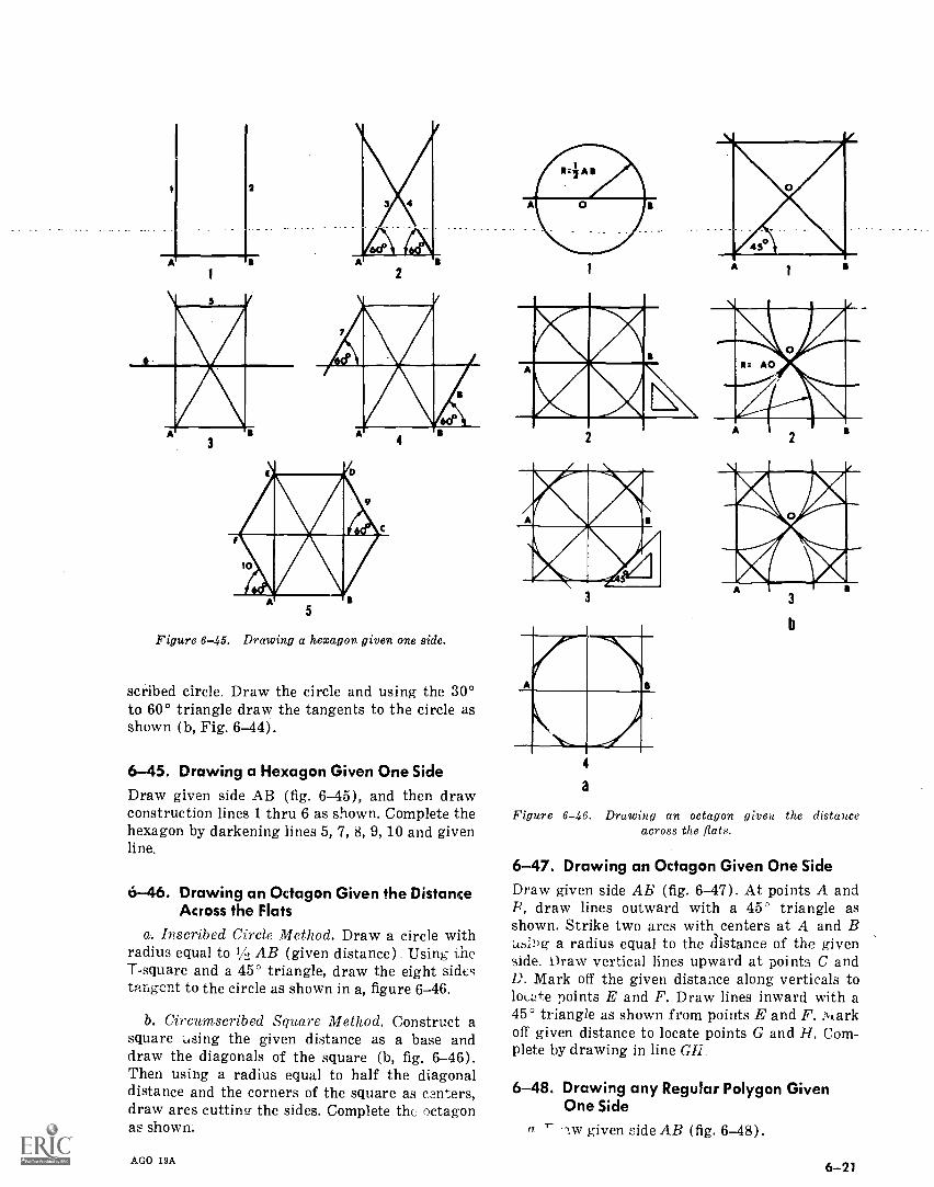
2
1 2
Figure 6-45. Drawing a hexagon given one side.
scribed circle. Draw the circle and using the 30°to 60° triangle draw the tangents to the circle asshown (b, Fig. 6-44).
6-45. Drawing a Hexagon Given One SideDraw given side AB (fig. 6-45), and then drawconstruction lines 1 thru 6 as shown. Complete thehexagon by darkening lines 5,7,8,9,10 and givenline.
6-46. Drawing an Octagon Given the DistanceAcross the Flats
a. Inscribed Circle Method. Draw a circle withradius equal to 1/, AB (given distance) Using theT-square and a 45° triangle, draw the eight sidestangent to the circle as shown in a, figure 6-46.
b. Circumscribed Square Method. Construct asquare using the given distance as a base anddraw the diagonals of the square (b, fig. 6-46).Then using a radius equal to half the diagonaldistance and the corners of the square as canters,draw arcs cutting the sides. Complete the octagonas shown.
AGO 19A
1
a
Figure 6-46. Drawing an octagon given the distanceacross the fiats.
6-47. Drawing an Octagon Given One SideDraw given side AB (fig. 6-47). At points A andB, draw lines outward with a 45' triangle asshown. Strike two arcs with centers at A and B-u6;:ig a radius equal to the distance of the givenside. Draw vertical lines upward at points C andD. Mark off the given distance along verticals toloezfe points E and F. Draw lines inward with a45° triangle as shown from points E and F. )quarkoff given distance to locate points G and H. Com-plete by drawing in line Gil
6-48. Drawing any Regular Polygon GivenOne Side
a 1- w given side AB (fig. 6-48).
6-21
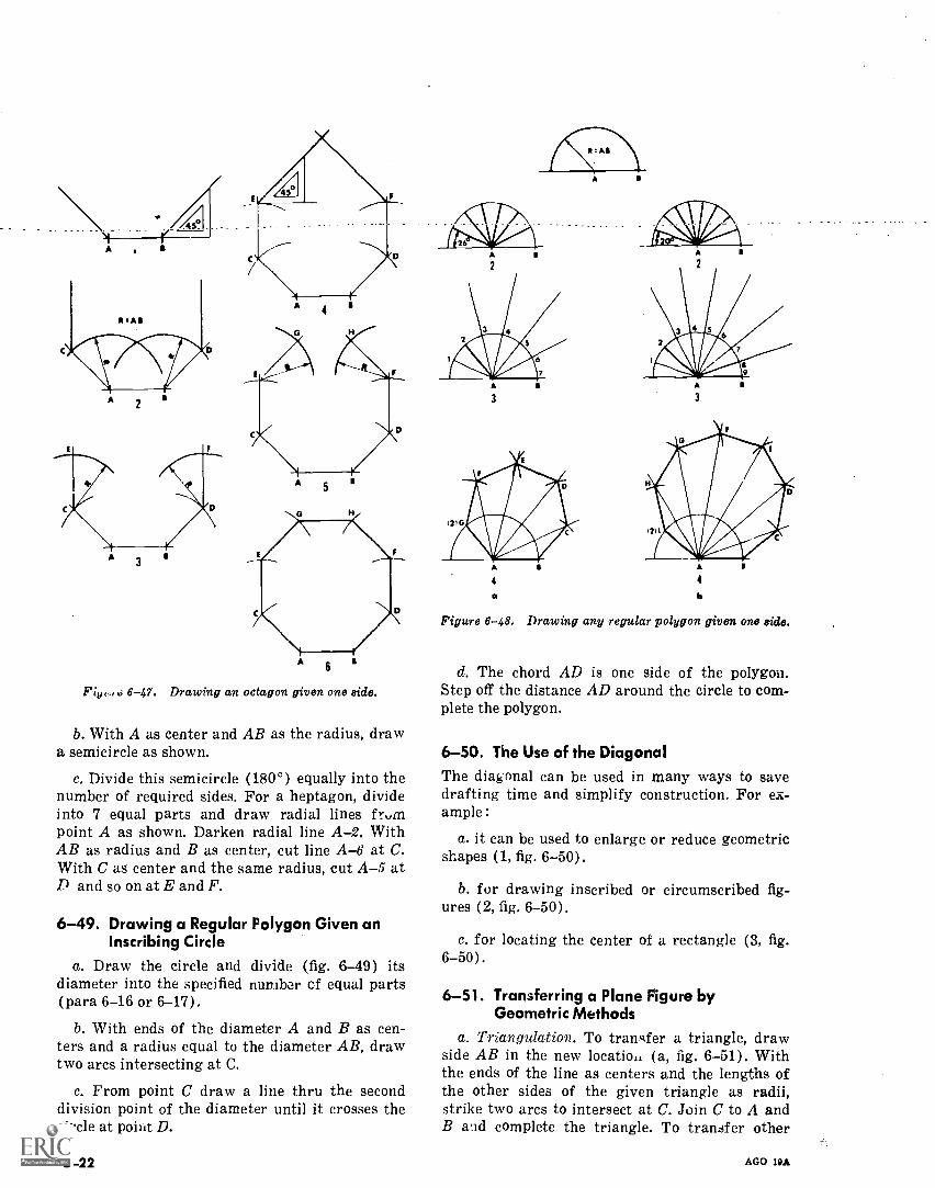
e 6-47. Drawing an octagon given one side.
b. With A as center and AB as the radius, drawa semicircle as shown.
c. Divide this semicircle (180°) equally into thenumber of required sides. For a heptagon, divideinto 7 equal parts and draw radial lines frninpoint A as shown. Darken radial lineA-2. WithAB as radius and B as center, cut line A-6 at C.With C as center and the same radius, cut A-5 atD and so on at E and F.
6-49. Drawing a Regular Polygon Given anInscribing Circle
a. Draw the circle and divide (fig. 6-49) itsdiameter into the specified nunibor cf equal parts(para 6-16 or 6-17).
b. With ends of the diameter A and B as cen-ters and a radius equal to the diameter AB, drawtwo arcs intersecting at C.
c. From point C draw a line thru the seconddivision point of the diameter until it crosses thecircle at point D.
6-22
4
a
4
b
Figure 6-48. Drawing any regular polygon given one side.
d. The chord AD is one side of the polygon.Step off the distance AD around the circle to com-plete the polygon.
6-50. The Use of the DiagonalThe diagonal can be used in many ways to savedrafting time and simplify construction. For ex-ample :
a. it can be used to enlarge or reduce geometricshapes (1, fig. 6-50).
b. for drawing inscribed or circumscribed fig-ures (2, fig. 6-50).
c. for locating the center of a rectangle (3, fig.6-50).
6-51. Transferring a Plane Figure byGeometric Methods
a. Triangulation. To transfer a triangle, drawside AB in the new location (a, fig. 6-51). Withthe ends of the line as centers and the lengths ofthe other sides of the given triangle as radii,strike two arcs to intersect at C. Join C to A andB and complete the triangle. To transfer other
AGO 19A

Figure 6-49. Drawing a regular polygon given aninscribing circle.
AGO 19A
2 3
Figure 6-60. The use of the diagonal.
polygons, divide them into triangles (b, fig. 6-51)and transfer each triangle individually.
b. Rectangle Method. Circumscribe a rectangleabout the given figure (c, fig. 6-51). Draw a con-gruent rectangle in the new location and locatethe vertexes of the given figure along the sidf,s ofthe new rectangle as s.hown.
6-23
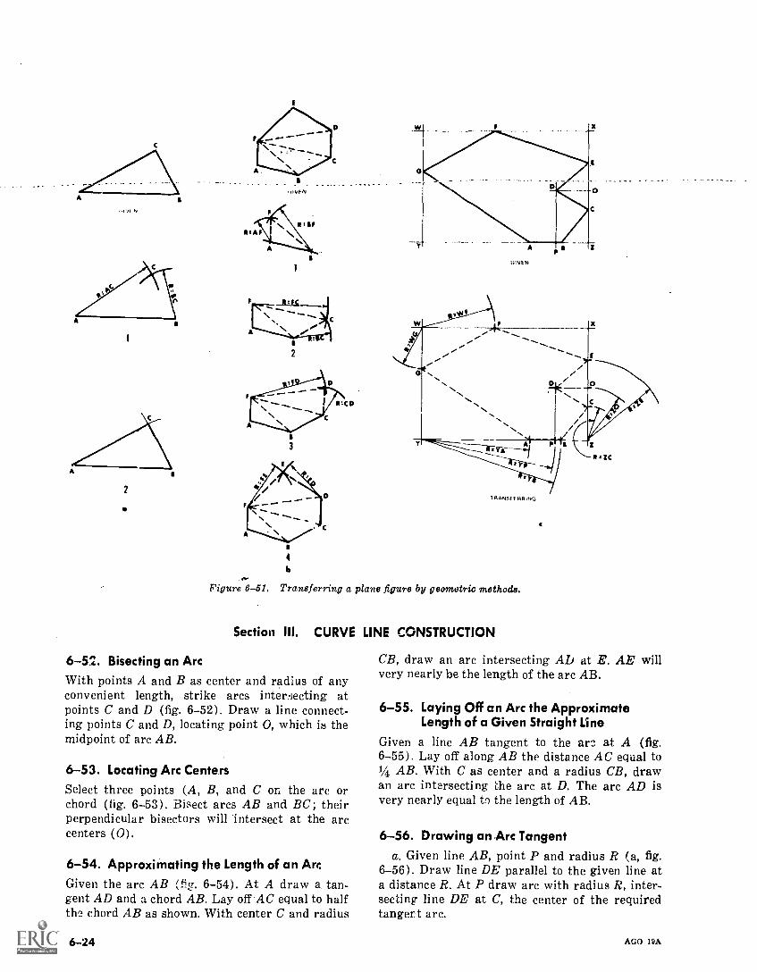
11./I N
2
2
3
Figure 6-51.
4
Is
TRANSFERRING
Transferring a plane figure by geometric methods.
Section III. CURVE LINE CONSTRUCTION
6-52. Bisecting an ArcWith points A and B as center and radius of anyconvenient length, strike arcs intenecting atpoints C and D (fig. 6-52). Draw a line connect-ing points C and D, locating point 0, which is themidpoint of arc AB.
6-53. Locating Arc CentersSelect three points (A, B, and C on the arc orchord (fig. 6-53). Bisect arcs AB and BC; theirperpendicular bisectors will intersect at the arccenters (0).
6-54. Approximating the Length of an ArcGiven the arc AB (fig. 6-54). At A draw a tan-gent AD and a chord AB. Lay off AC equal to halfthe chord AB as shown. With center C and radius
6-24
CB, draw an arc intersecting AD at E. AE willvery nearly be the length of the arc AB.
6-55. Laying Off an Arc the ApproximateLength of a Given Straight Line
Given a line AR tangent to the are at A (fig.6-55). Lay off along AB the distance AC equal to1/4 AB. With C as center and a radius CB, drawan arc intersecting the arc at D. The arc AD isvery nearly equal to the length of AB.
6-56. Drawing an Arc Tangenta. Given line AB, point P and radius R (a, fig.
6-56). Draw line DE parallel to the given line ata distance R. At P draw arc with radius R, inter-secting line DE at C, the center of the requiredtangent arc.
AGO 19A
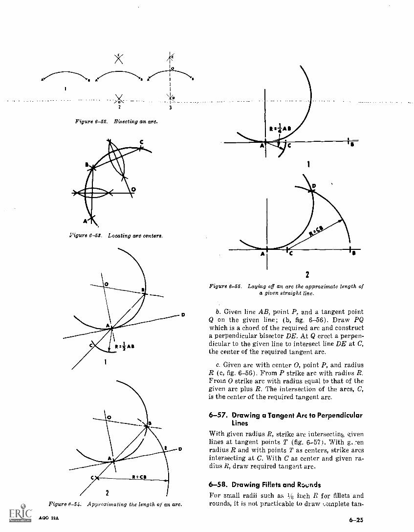
A A
\
2
Figure 6-52. Bisecting an arc.
Figure 6-53. Locating arc centers.
3
2
Figure 6-54. Approximating the length of an arc.
AGO 19A
1
2
Figure 6-55. Laying off an arc the approximate length ofa given straight line.
b. Given line AB, point P, and a tangent pointQ on the given line ; (b, fig. 6-56). Draw PQwhich is a chord of the required arc and constructa perpendicular bisector DE. At Q erect a perpen-dicular to the given line to intersect line DE at C,the center of the required tangent arc.
c. Given arc with center 0, point P, and radiusR (c, fig. 6-56). From P strike arc with radius R.From 0 strike arc with radius equal to that of thegiven arc plus R. The intersection of the arcs, C,is the center of the required tangent arc.
6-57. Drawing a Tangent Arc to PerpendicularLines
With given radius R, strike arc intersecting givenlimes at tangent points T (fig. 6-571. With g, -enradius R and with points T as centers, strike arcsintersecting at C. With C as center and given ra-dius R, draw required tangent arc.
6-58. Drawing Fillets and R.wndsFor small radii such as 1/8 inch R for fillets androunds, it is not practicable to draw complete tan-
6-25
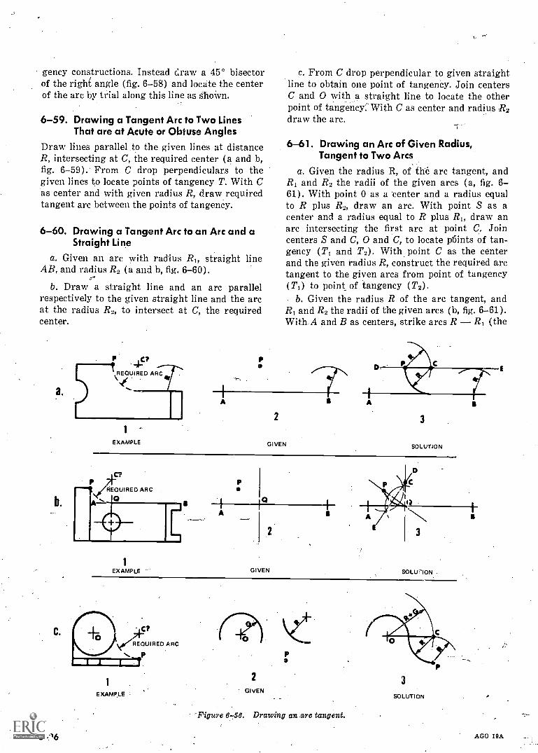
gency constructions. Instead Craw a 45° bisectorof the right angle (fig. 6-58) and locate the centerof the arc by trial along this line as ShoWn.
6-59. Drawing a Tangent Arc to Two LinesThat are at Acute or Obtuse Angles
Draw lines parallel to the given lines at distanceR, intersecting at C, the required center (a and b,fig. 6 -59). From C drop perpendiculars to thegiven lines to locate points of tangency T. With Cas center and with given radius R, draw requiredtangent arc between the points of tangency.
6-60. Drawing a Tangent Arc to an Arc and aStraight Line
a. Given an arc with radius RI, straight lineAB, and radius R2 (a and b, fig. 6-60).
b. Draw a straight line and an arc parallelrespectively to the given straight line and the arcat the radius R2, to intersect at C, the requiredcenter.
a.
C.
6-16
P 45?REQUIRED ARC
NeC
1
EXAMPLE
A
c. From C drop perpendicular to given straightline to obtain one point of tangenCy. Join centersC and 0 with a straight line to locate the otherpoint of tangency:With C as center and radius R2draw the arc.
-7
6-61. Drawing an Arc of Given Radius,Tangent to Two Arcs
a. Given the radius R, of the arc tangent, andR1 and R2 the radii of the given arcs (a, fig. 6-61). With point 0 as a center and a radius equalto R plus R2, draw an arc. With point S as acenter and a radius equal to R plus RI, draw anarc intersecting the first arc at point C. Joincenters S and C, 0 and C, to locate p6ints of tan-gency (TI and T2). With point C as the centerand the given radius R, construct the required arctangent to the given arcs from point of tangency(T1) to point of tangency (T2).
b. Given the radius R of the arc tangent, andR1 and R2 the radii of the given arcs (b, fig. 6-61).With A and B as centers, strike arcs R R1 (the
2
GIVEN
3
SOLUTION
PREQUIRED ARC
1
EXAMPLE
A
GIVEN SOLU'ilON
v4CT
REQUIRED ARC
P
EXAMPLE
2
GIVEN
Figure 6 -56. Drawing an arc tangent.
3
SOLUTION
AGO 19A
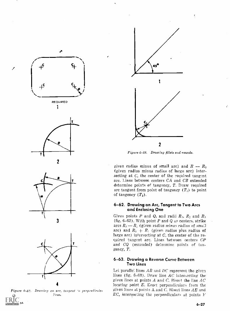
45
REQUIRED
\;
2
3
4
Figure 6-57. Drawing an arc, tangent 'o perpendicula)
AGO /9A
43°
2
Figure 6-58. Drawing fillets and rounds.
given radius minus of small arc) and R R2(given radius minus radius of large arc) inter-secting at C, the center of the required tangentarc. Lines between centers CA and CB extendeddetermine points of tangency, T. Draw requiredarc tangent from point of tangency (TO to pointof tangency (T2).
6-62. Drawing an Arc, Tangent to Two Arcsand Enclosing One
Given points P and Q, and radii RI, Rn and R3(fig. 6-62). With point P and Q as centers, strikearcs R, R, (given radius minus radius of smallarc) and R3 + R, (given radius plus radius oflarge arc) intersecting at C, the center of the re-quired tangent arc. Lines between centers CPand CQ (extended) determine points of tan-gency, T.
6-63. Drawing a Reverse Curve BetweenTwo Lines
Let parallel lines AB and DC represent the givenlines (fig. 6-63). Draw line AC intersecting thegiven lines at points A and C. Bisect the line AClocating point E. Erect perpendiculars from thegiven lines at points A and C. Bisect lines AE andEC, intersecting the perpendiculars at points F
6 -27
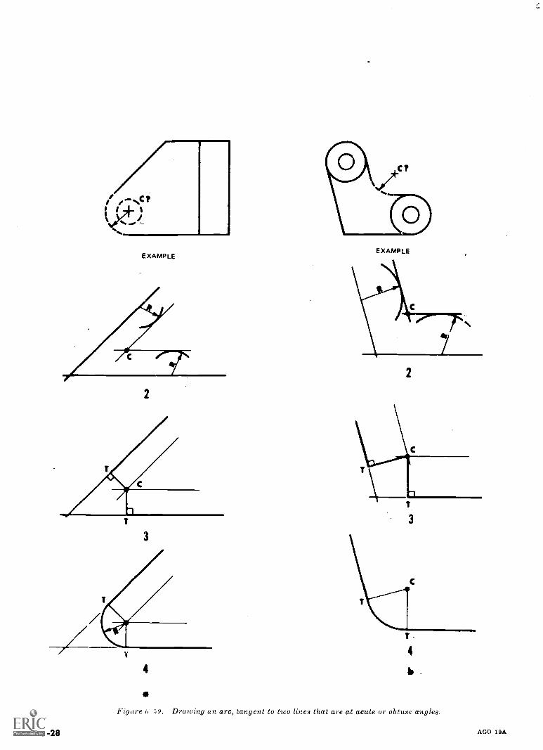
EXAMPLE
2
3
4
Figure G -59. Drawing an arc, tangent to two lines that are at acute or obtuse angles.
EXAMPLE
2
C
4
b .
6-28 AGO 19A
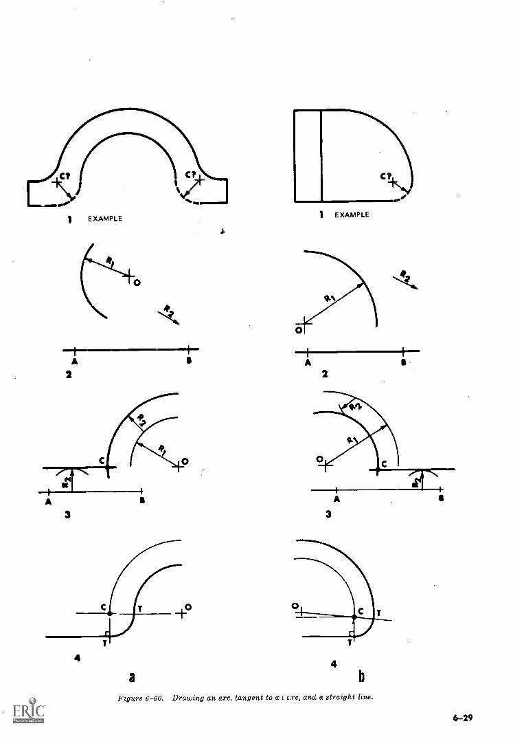
1
A
2
EXAMPLE
AI
4
AGO 19A
a
1 EXAMPLE
A2
3
4b
Figure 6-60. Drawing an arc, tangent to a t arc, and a straight line.
6-29
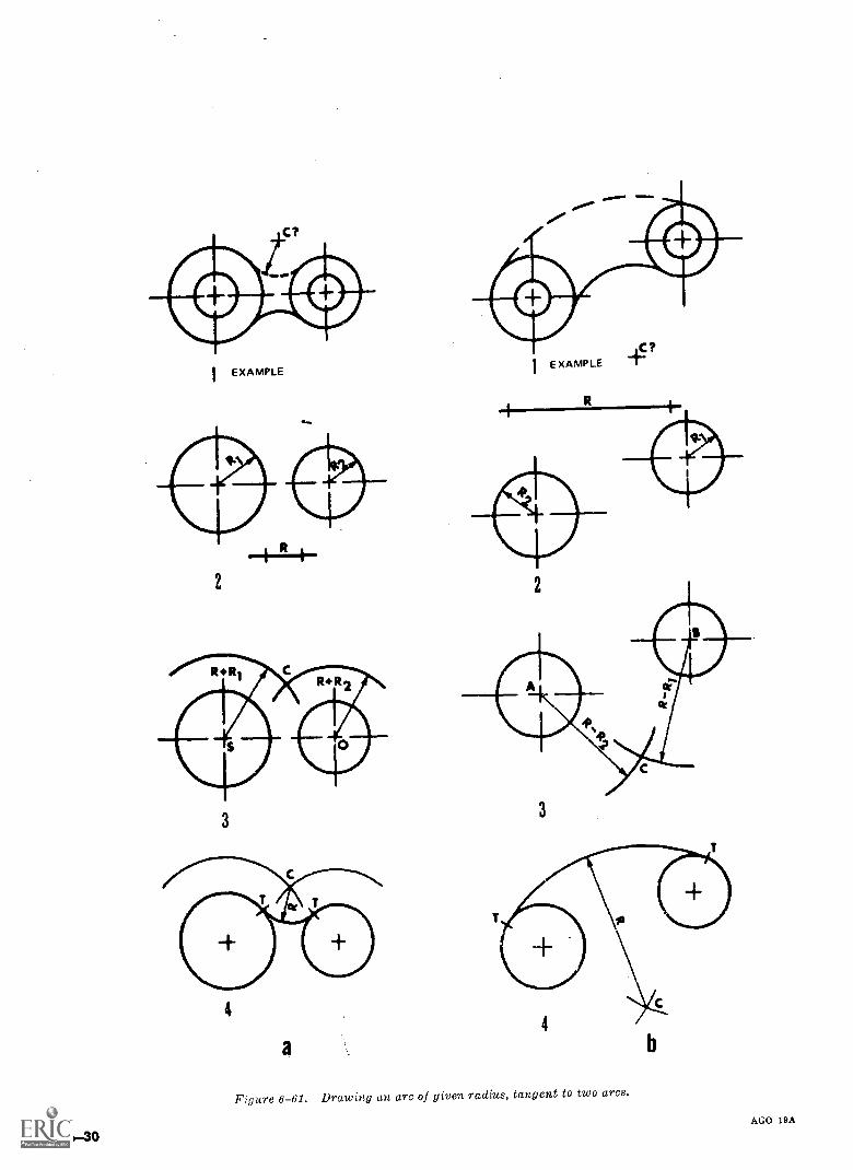
I EXAMPLE
2
3
4
a
3
Figure 6-61. Drawing an arc of given radius, tangent to two arcs.
b
AGO 19A
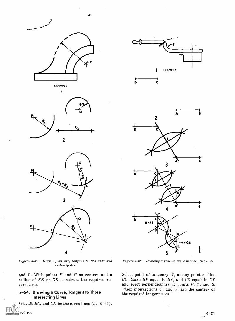
EXAMPLE
1
R3
2
3
Figure 6-22. Drawing an arc, tangent to two arcs andenclosing one.
and G. With points F and G as centers and aradius of FE or GE, construct the required re-verse arcs.
5-64. Drawing a Curve, Tangent to ThreeIntersecting Lines
Let AB, BC, and CD be the given lines (fig. 6-64).
AGO
1 EXAMPLE
C
A
2
3
Figure 6-63. Drawing a reverse curve between two lines.
Select point of tangency, T, at any point on lineBC. Make BP equal to BT, and CS equal to CTand erect perpendiculars at points P, T, and S.Their intersections 0, and 0, are the centers ofthe required tangent arcs.
6-31
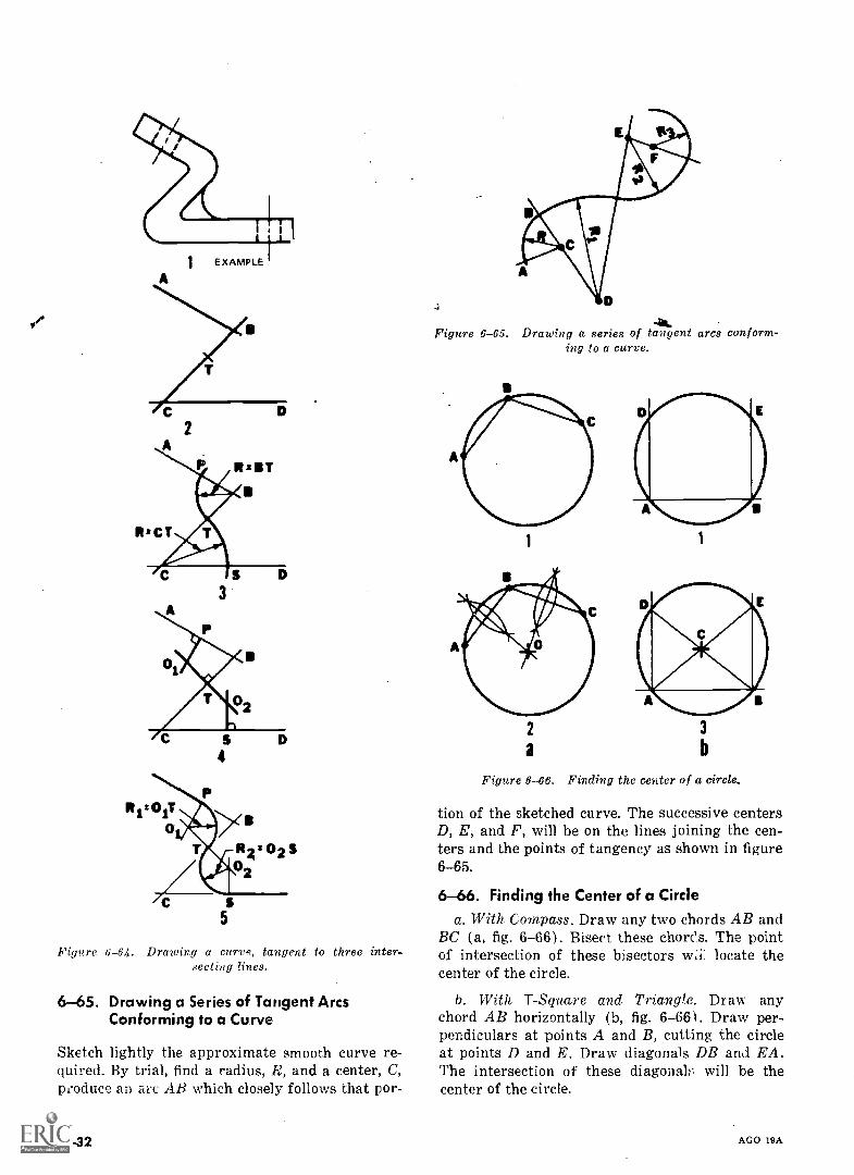
2
3
4
Figure 6-64. Drawing a curve, tangent to three inter -.ecting
6-65. Drawing a Series of Tangent ArcsConforming to a Curve
Sketch lightly the approximate smooth curve re-quired. By trial, find a radius, R, and a center, C,produce an an: AB which closely follows that por-
6-32
Figure 6-65. Drawing a series of tangent arcs conform-ing to a curve.
a b
Figure 6-66. Finding the center of a circle.
tion of the sketched curve. The successive centersD, E, and F, will be on the lines joining the cen-ters and the points of tangency as shown in figure6-65.
6-66. Finding the Center of a Circlea. With. Compass. Draw any two chords AB and
BC (a, fig. 6-66). Bisect these chorOs. The pointof intersection of these bisectors locate thecenter of the circle.
b. With T- Square and Triangle. Draw anychord AB horizontally (b, fig. 6-661. Draw per-pendiculars at points A and B, cutting the circleat points D and E. Draw diagonals DB and EA.The intersection of these diagona will be thecenter of the circle.
AGO 19A
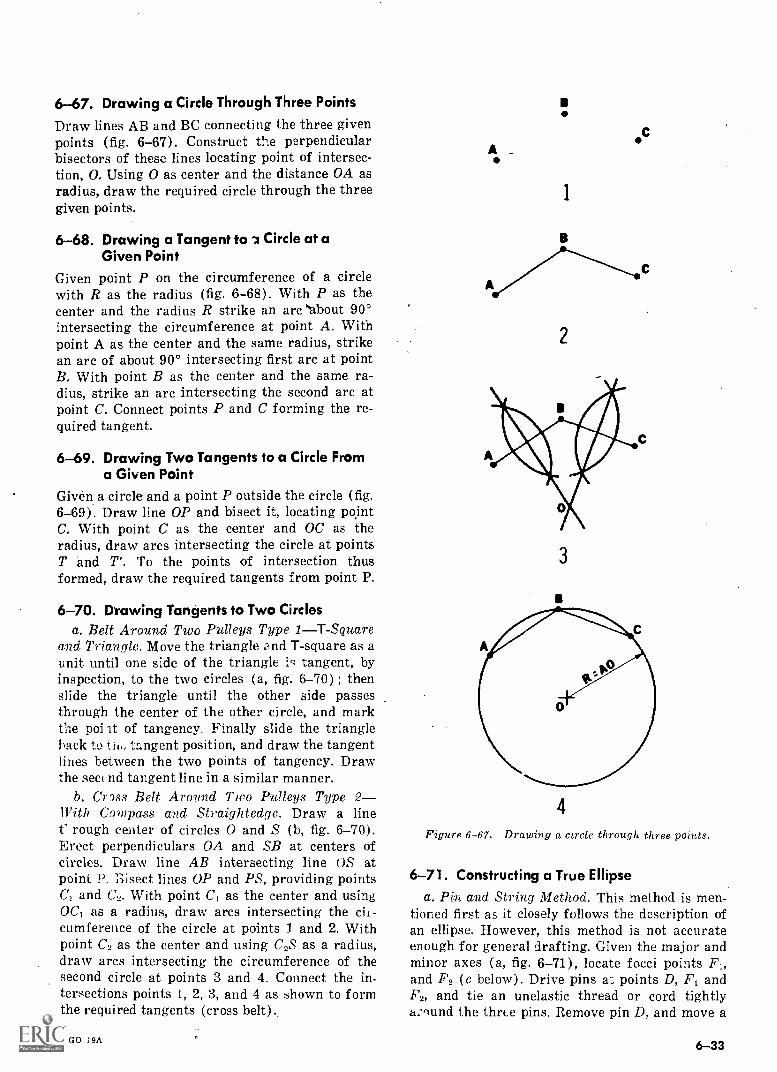
6-67. Drawing a Circle Through Three Points
Draw lines AB and BC connecting the three givenpoints (fig. 6-67). Construct t!i.e perpendicularbisectors of these lines locating point of intersec-tion, 0. Using 0 as center and the distance OA asradius, draw the required circle through the threegiven points.
6-68. Drawing a Tangent tol Circle at aGiven Point
Given point P on the circumference of a circlewith R as the radius (fig. 6-68). With P as thecenter and the radius R strike an arc "about 90°intersecting the circumference at point A. Withpoint A as the center and the same radius, strikean arc of about 90° intersecting first arc at pointB. With point B as the center and the same ra-dius, strike an arc intersecting the second arc atpoint C. Connect points P and C forming the re-quired tangent.
6-69. Drawing Two Tangents to a Circle Froma Given Point
Given a circle and a point P outside the circle (fig.6-69). Draw line OP and bisect it, locating pointC. With point C as the center and OC as theradius, draw arcs intersecting the circle at pointsT and T'. To the points of intersection thusformed, draw the required tangents from point P.
6-70. Drawing Tangents to Two Circlesa. Belt Around Two Pulleys Type 1 T- Square
and Triangle. Move the triangle and T-square as aunit until one side of the triangle iq tangent, byinspection, to the two circles (a, fig. 6-70) ; thenslide the triangle until the other side passesthrough the center of the other circle, and markthe poi it of tangency. Finally slide the triangleback tti,, tangent position, and draw the tangentlines between the two points of tangency. Drawthe second tangent line in a similar manner.
b. Cross Belt Around Two Pulleys Type 2With Copt -pass and Straightedge. Draw a linet' rough center of circles 0 and S (b, fig. 6-70).Erect perpendiculars OA and SB at centers ofcircles. Draw line AB intersecting line OS atpoint P. Bisect lines OP and PS, providing pointsC, and C2. With point C, as the center and usingOC, as a radius, draw arcs intersecting the cir-cumference of the circle at points 1 and 2. Withpoint C2 as the center and using C25 as a radius,draw arcs intersecting the circumference of thesecond circle at points 3 and 4. Connect the in-tersections points 1, 2, 3, and 4 as shown to formthe required tangents (cross belt).
AGO 19A
I
A _
C
2
3
4
Figure 6-67. Drawing a circle through three points.
6-71. Constructing a True Ellipsea. Pin and String Method. This method is men-
tioned first as it closely follows the description ofan ellipse. However, this method is not accurateenough for general drafting. Given the major andminor axes (a, fig. 6-71), locate focci points F1,and F2 (c below). Drive pins at points D, F, andF2, and tie an unelastic thread or cord tightly:1;7,-mnd the three pins. Remove pin D, and move a
6-33
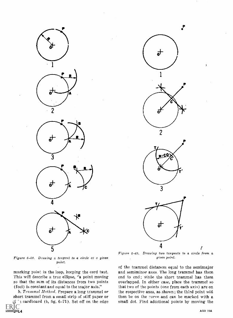
Figure 6-68. Drawing a tangent to a circle at a givenpoint.
marking point in the loop, keeping the cord taut.This will describe a true ellipse, "a point movingso that the sum of its distances from two points(foci) is constant and equal to the major axis."
b. Trammel Method. Prepare a long trammel orshort trammel from a small strip of stiff paper orthin cardboard (b, fig. 6-71). Set off on the edge
6-34
P
Figure 6-69. Drawing two tangents to a circle from agiven point.
of the trammel distances equal to the semimajorand semiminor axes. The long trammel has themend to end ; while the short trammel has themoverlapped. In either case, place the trammel sothat two of the points (one from each axis) are onthe respective axes, as shown ; the third point willthen be on the curve and can be marked with asmall dot. Find adaitional points by moving the
AGO 19A
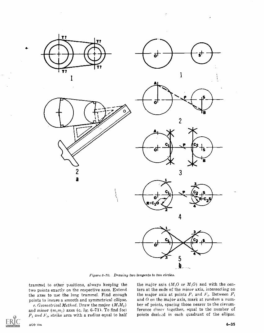
T?
T?
I1
2
a3
4
Figure 6-70. Drawing two tangents to two circles.
trammel to other positions, always keeping thetwo points exactly on the respective axes. Extendthe axes to use the long trammel. Find enoughpoints to insure a smooth and symmetrical ellipse.
c. Geometrical Method. Draw the major (MIM2)and minor (mom) axes (c, fig. 6-711. To find fociF1 and F2, strike arcs with a radius equal to half
AGO 19A
the major axis (M10 or M.,0) and with the cen-ters at the ends of the minor axis, intersecting onthe major axis at points F1 and F2. Between F1and 0 on the major axis, mark at random a num-ber of points, spacing those nearer to the circum-ference closer together, equal to the number ofpoints desiiod in each quadrant of the ellipse.
6-35
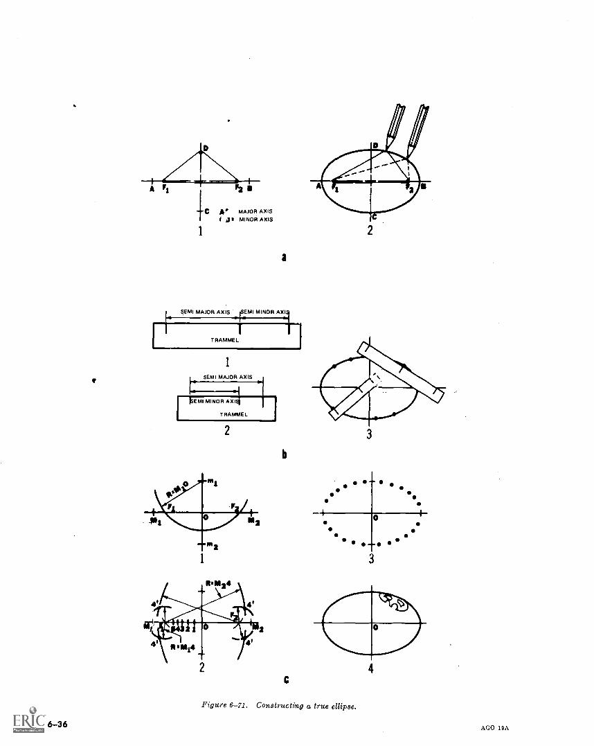
6-36
F2
C A MAJOR AXISOa MINOR AXIS
a
SEMI MAJOR AXIS 4EMI MINOR AXI
1
TRAMMEL
ISEMI MAJOR AXIS
I
2
b
C
0
3
Figure 6-71. Constructing a true ellipse.
AGO 19A
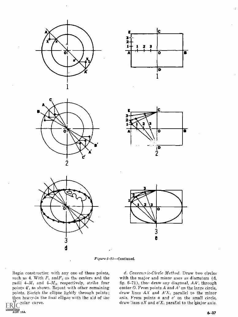
3-1 1 2 3A
C
0
Figure 6-71Continued.
Begin construction with any one of these points,such as 4. With F, andF2 as the centers and theradii 4-31, and 4M2, respectively, strike fourpoints 4', as shown. Repeat with other remainingpoints. Sketch the ellipse lightly through points;then hea,,y-in the final ellipse with the aid of theirregular curve.
AGO 19A;
3e
d. Concen[? ic- Circle Method. Draw two circleswith the major and minor axes as diameters (d,fig. 6-71), thei, draw any diagonal, AA', throughcenter 0. From points A and A' on the large circle,draw lines AX and A'Xi parallel to the minoraxis. From points a and a' on the small circle,draw lines aX and a'Xi parallel to the ',xi ajor axis.
6-47
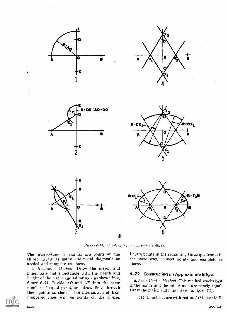
A
3a
Figure 6-72. Constructing an approximate ellipse.
The intersections X and X, are points on theellipse. Draw as many additional diagonals asneeded and complete as above.
e. Rectangle Method. Draw the major andminor axis-and a rectangle with the length andheight of the major and minor axis as shown in e,figure 6-71. Divide AO and AE into the samenumber of equal parts, and draw lines throughthese points as shown. The intersection of like-numbered lines will be points on the ellipse.
6-38
Locate points in the remaining three quadrants inthe same way, connect points and complete asabove.
6-72. Constructing an Approximate Ellipsea. Four-Center Method. This method works best
if the major and the minor axis are nearly equal.Draw the major and minor axis (a, fig. 6-72).
(1) Construct arc with radius AO to locate E.
AGO 19A.
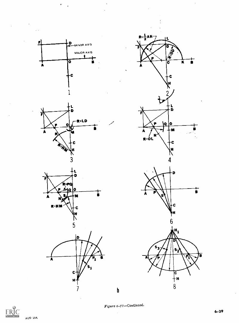
A0
M
MINOR AXIS
AXIS
C
1
3
5
b
Figure 6-77Continued.
AGO 19A
8
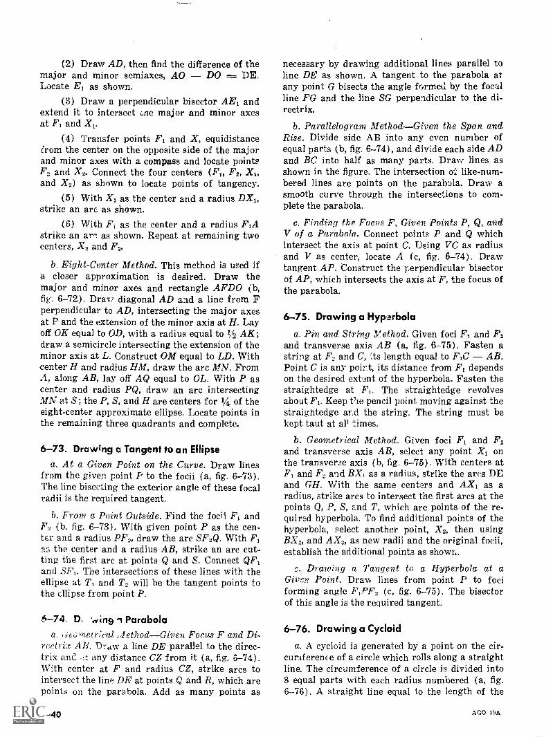
(2) Draw AD, then find the difference of themajor and minor semiaxes, AO DO = DE.Locate El as shown.
(3) Draw a perpendicular bisector AEi andextend it to intersect Lne major and minor axesat F1 and X,.
(4) Transfer points F1 and X, equidistancefrom the center on the opposite side of the majorand minor axes with a compass and locate pointsF., and X2. Connect the four centers (F1, F2, XI,and X2) as shown to locate points of tangency.
(5) With X1 as the center and a radius DX1,strike an arc as shown.
(6) With FT as the center and a radius F1Astrike an ar,,. as shown. Repeat at remaining twocenters, X, and F2.
b. Eight-Center Method. This method is used ifa closer approximation is desired. Draw themajor and minor axes and rectangle AFDO (b,fig, 6-72). Draw diagonal AD and a line from Fperpendicular to AD, intersecting the major axesat P and the extension of the minor axis at H. Layoff OK equal to OD, with a radius equal to 1/2 AK;draw a semicircle intersecting the extension of theminor axis at L. Construct OM equal to LD. Withcenter H and radius HM, draw the arc M.N. FromA, along AB, lay off AQ equal to OL. With P ascenter and radius PQ, draw an arc intersectingMN at S; the P, S, and H are centers for 1/4 of theeight-center approximate ellipse. Locate points inthe remaining three quadrants and complete.
6-73. Drawing a Tangent to an Ellipsea. At a Given Point on the Curve. Draw lines
from the given point P to the focii (a, fig. 6-73).The line bisecting the exterior angle of these focalradii is the required tangent.
b. From a Point Outside. Find the focii F1 andF2 (b, fig. 6-73). With given point P as the cen-ter and a radius PP', draw the arc SF2Q. With F1as the center and a radius AB, strike an arc cut-ting the first arc at points Q and S. Connect QF,and SF,. The intersections of these lines with theellipse at T, and T2 will be the tangent points tothe ellipse from point P.
6-74. D, Parabolaa. 1;e6uleirical :lethodGiven Focus F and Di-
reetrix AB. Draw a line DE parallel to the direc-trix and :t any distance CZ from it (a, fig. 6-74).
With center at F and radius CZ, strike arcs tointersect the line DE at points Q and R, which arepoints on the parabola. Add as many points as
NI 6-40
necessary by drawing additional lines parallel toline DE as shown. A tangent to the parabola atany point G bisects the angle formed by the focalline FG and the line SG perpendicular to the di-rectrix.
b. Parallelogram MethodGiven the Span andRise. Divide side AB into any even number ofequal parts (b, fig. 6-74), and divide each side ADand BC into half as many parts. Draw lines asshown in the figure. The intersection o like-num-bered lines are points on the parabola. Draw asmooth curve through the intersections to com-plete the parabola.
c. Finding the Focus F, Given Points P, Q, andV of a Parabola. Connect points P and Q whichintersect the axis at point C. rising VC as radiusand V as center, locate A (c, fig. 6-74). Drawtangent AP. Construct the perpendicular bisectorof AP, which intersects the axis at F, the focus ofthe parabola.
6-75. Drawing a Hyparbola
a. Pin and String Method. Given foci F1 and F2and transverse axis AB (a, fig. 6-75). Fasten astring at F, and C, lts length equal to F,C AB.Point C is any point, its distance from F1 dependson the desired extent of the hyperbola. Fasten thestraightedge at F1. The straightedge revolvesabout F1. Keep Vie pencil point moving against thestraightedge and the string. The string must bekept taut at all times.
b. Geometrical Method. Given foci F1 and F2and transverse axis AB, select any point X1 onthe transverse axis (b, fig. 6-75). With centers atF1 and F., and BX, as a radius, strike the arcs DEand GH. With the same centers and AX, as aradius, strike arcs to intersect the first arcs at thepoints Q, P, S, and T, which are points of the re-quired hyperbola. To find additional points of thehyperbola, select another point, X2, then usingBX2, and AX2, as new radii and the original focii,establish the additional points as shown.
Drawing a Tangent to a Hyperbola at aGiven Point. Draw lines from point P to fociforming angle F,PF2 (c, fig. 6-75). The bisectorof this angle is the required tangent.
6-76. Drawing a Cycloid
a. A cycloid is generated by a point on the cir-cumference of a circle which rolls along a straightline. The circumference of a circle is divided into8 equal parts with each radius numbered (a, fig.6-76). A straight line equal to the length of the
AGO 19A
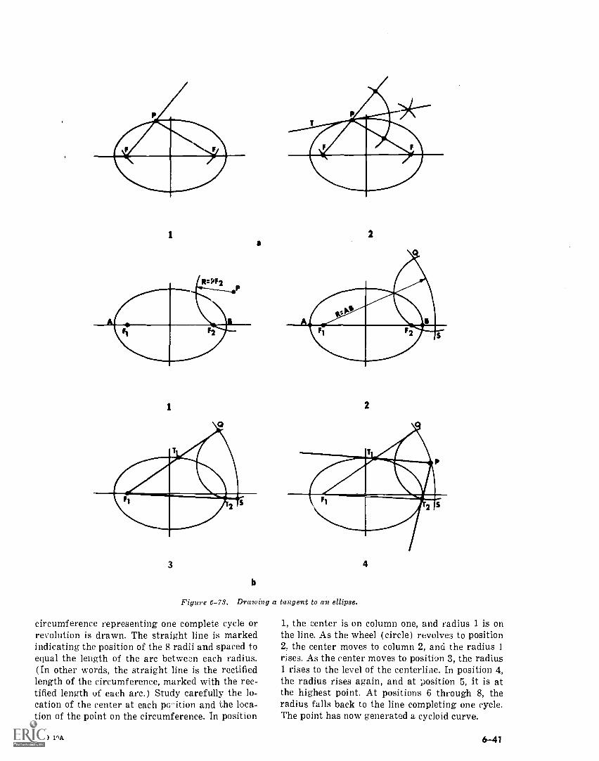
a
3
b
2
2
Figure 6-73. Drawing a tangent to an ellipse.
circumference representing one complete cycle orrevolution is drawn. The straight line is markedindicating the position of the 8 radii and spaced toequal the length of the arc between each radius.(In other words, the straight line is the rectifiedlength of the circumference, marked with the rec-tified length of each arc.) Study carefully the lo-cation of the center at each pc7ition and the loca-tion of the point on the circumference. In position
AGO 1.9A
4
1, the center is on column one, and radius 1 is onthe line. As the wheel (circle) revolves to position2; the center moves to column 2, and the radius 1rises. As the center moves to position 3, the radius1 rises to the level of the centerline. In position 4,the radius rises again, and at position 5, it is atthe highest point. At positions 6 through 8, theradius falls back to the line completing one cycle.The point has now generated a cycloid curve.
6-41
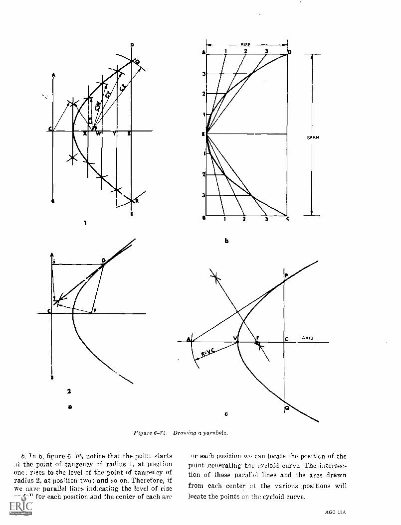
D
1
2
a
b
a
SPAN
Figure 6-74. Drawing a parabola.
b. In b, figure 6-76, notice that the point startsAL the point of tangency of radius 1, at positionone; rises to the level of the point of tangency ofradius 2, at position two; and so on. Therefore, ifwe have parallel lines indicating the level of riseor fall for each position and the center of each arc
6-42
or each position we can locate the position of thepoint generating the cycloid curve. The intersec-tion of these parallel lines and the arcs drawnfrom each center the various ,positions willlocate the points on the cycloid curve.
AGO 19A
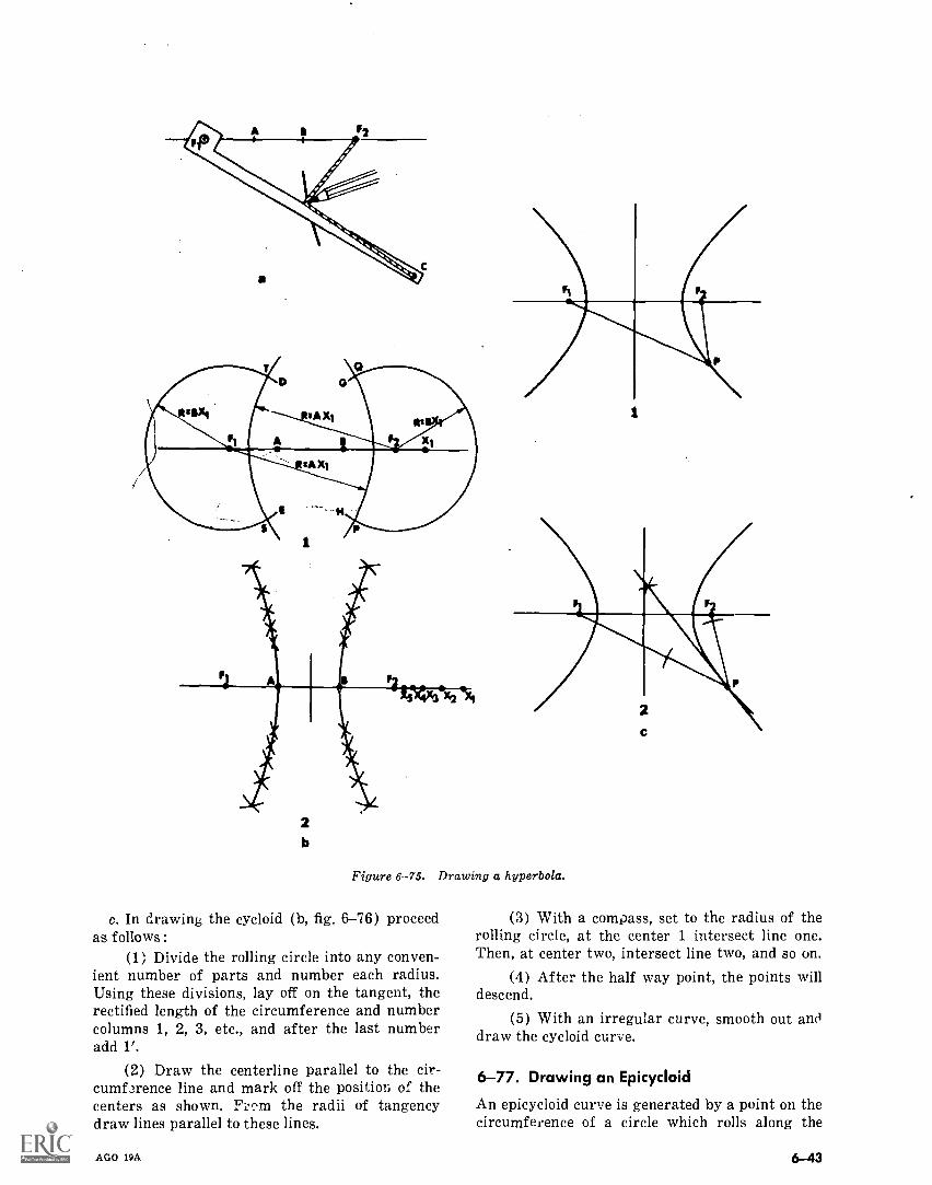
2b
Figure 6--75. Drawing a hyperbola.
c. In drawing the cycloid (b, fig. 6-76) proceedas follows :
(1) Divide the rolling circle into any conven-ient number of parts and number each radius.Using these divisions, lay off on the tangent, therectified length of the circumference and numbercolumns 1, 2, 3, etc., and after the last numberadd 1'.
(2) Draw the centerline parallel to the cir-cumf2rence line and mark off the position of thecenters as shown. F: ^m the radii of tangencydraw lines parallel to these lines.
AGO 19A
(3) With a compass, set to the radius of therolling circle, at the center 1 intersect line one.Then, at center two, intersect line two, and so on.
(4) After the half way point, the points willdescend.
(5) With an irregular curve, smooth out ancldraw the cycloid curve.
6-77. Drawing an Epicycloid
An epicycloid curve is generated by a point on thecircumference of a circle which rolls along the
6-43
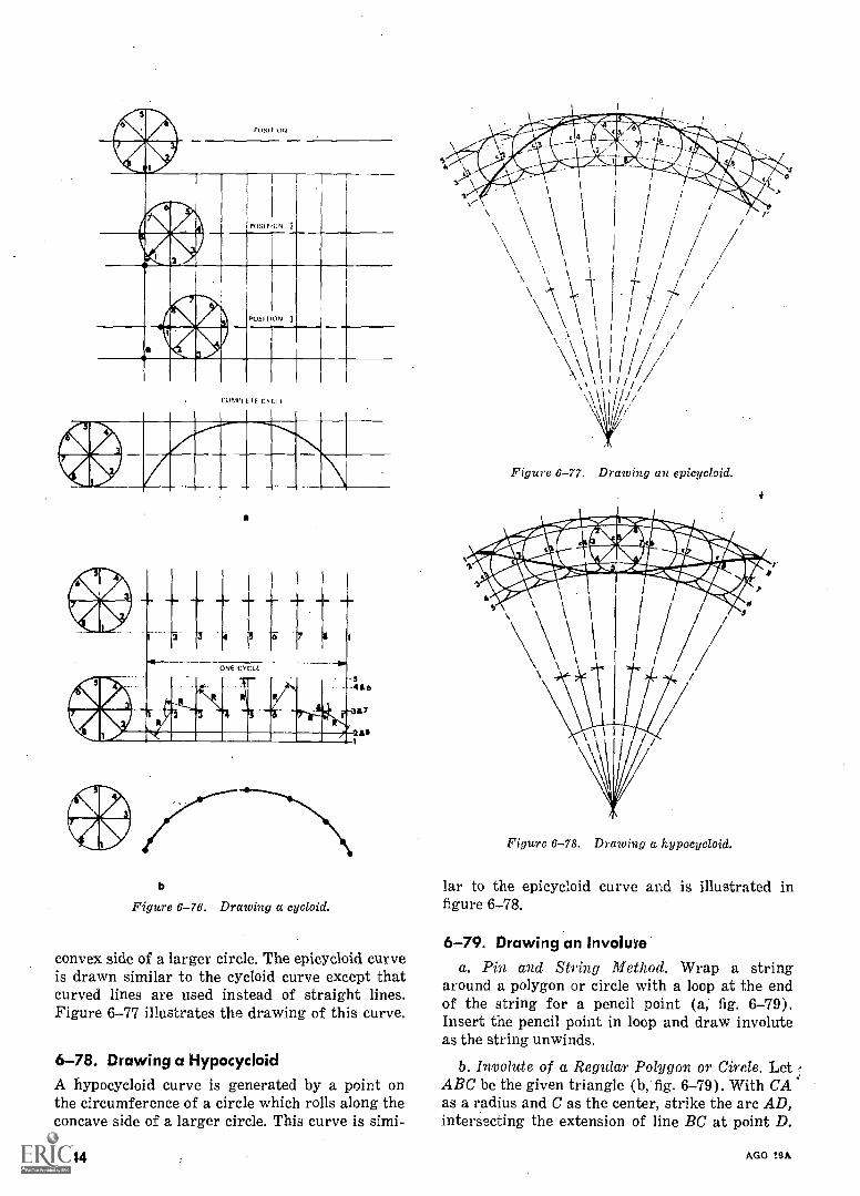
CUMIN IF C.% C1 F
2 4 3
ONF CYCLE
7
b
Figure 6-76. Drawing a cycloid.
convex side of a larger circle. The epicycloid curveis drawn similar to the cycloid curve except thatcurved lines are used instead of straight lines.Figure 6-77 illustrates the drawing of this curve.
6-78. Drawing a HypocycloidA hypocycloid curve is generated by a point onthe circumference of a circle which rolls along theconcave side of a larger circle. This curve is simi-
6-44
Figure 6-77. Drawing an epicycloid.
Figure 6-78. Drawing a hypocycloid.
lar to the epicycloid curve and is illustrated infigure 6-78.
6-79. Drawing an Involuvea. Pin and String Method. Wrap a string
around a polygon or circle with a loop at the endof the string for a pencil point (a; fig. 6-79).Insert the pencil point in loop and draw involuteas the string unwinds.
b. Involute of a Regular Polygon or Circle. Let r.ABC be the given triangle (b, fig. 6-79). With CAas a radius and C as the center, strike the arc AD,intersecting the extension of line BC at point D.
AGO 19A
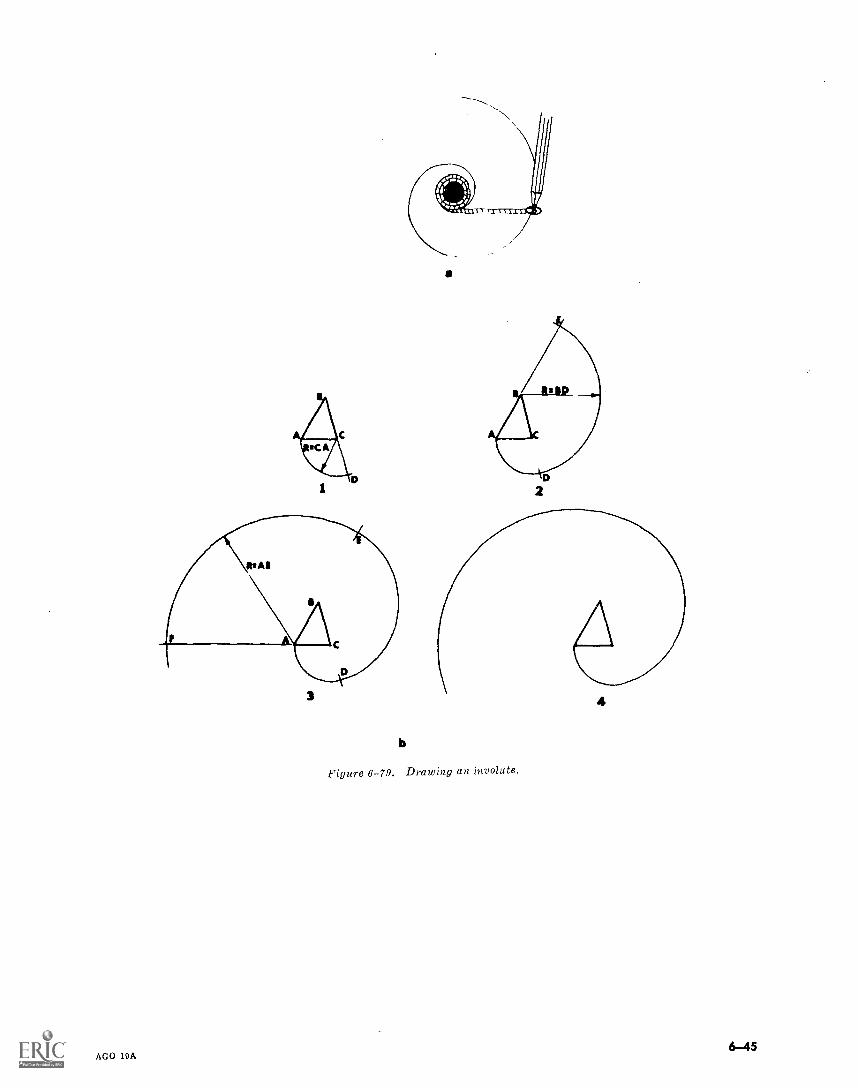
3
AGO 19A
b
a
Figure 6-79. Drawing an involute.
4
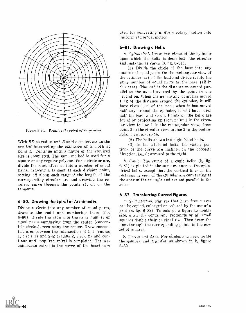
Figure 6-80. Drawing the spiral of Archimedes.
10
With BD as radius and B as the center, strike thearc DE intersecting the extension of line AB atpoint E. Continue until a figure of the requiredsize is completed. The same method is used for asquare or any regular polygon. For a circle or arc,divide the circumference into a number of equalparts, drawing a tangent at each division point,setting off along each tangent the length of thecorresponding circular arc and drawing the re-quired curve through the points set off on thetangents.
6-80. Drawing the Spiral of ArchimedesDivide a circle into any number of equal parts,drawing the radii and numbering them (fig.6-80). Divide the radii into the same number ofequal parts numbering from the center (concen-tric circles), zero being the center. Draw concen-tric arcs between the intersection of 1-1 (radius1, circle 1) and 2-2 (radius 2, circle 2) and con-tinue until required spiral is completed. The Ar-chimedean spiral is the curve of the heart cam
6-46
used for converting uniform rotary motion intouniform reciprocal motion.
6-81. Drawing a Helixa. Cylindrical. Draw two views of the cylinder
upon which the helix is describedthe circularand rectangular views (a, fig. 6-81).
(1) Divide the circle of the base into anynumber of eqtial parts. On the rectangular view ofthe cylinder, sear off the lead and divide it into thesame number of equal parts as the base (12 inthis case). The lead is the distance measured par-allel to the axis traversed by the point in onerevolution. When the generating point has moved1,12 of the distance around the cylinder, it willhave risen 1,12 of the lead; when it has movedhalf-way around the cylinder, it will have risenhalf the lead, and so on. Points on the helix arefound by projecting up from point 1 in the circu-lar view to line 1 in the rectangular view, frompoint 2 in the circular view to line 2 in the rectan-gular view, and so on.
(2) The helix shown is a right-hand helix.(3) In the left-hand helix, the visible por-
tions of the curve are inclined in the oppositedirection, i.e., downward to the right.
b. Conic. The curve of a conic helix (b, fig.
6-81) is plotted in the same manner as the cylin-drical helix, except that the vertical lines in therectangular view of the cylinder are converging atthe apex of the triangle and are not parallel to thesides.
6-82. Transferring Curved Figuresa. Grid Method. Figures that have free curves
can be copied, enlarged or reduced by the use of agrid (a, fig. 6-82), To enlarge a figure to doublesize, draw the containing rectangle or all smallsquares double their original size. Then draw thelines through the corresponding points in the newset of squares.
b. Circles and Ares. For circles and arcs. locatethe centers and transfer as shown in b, figure6-82.
AGO I9A
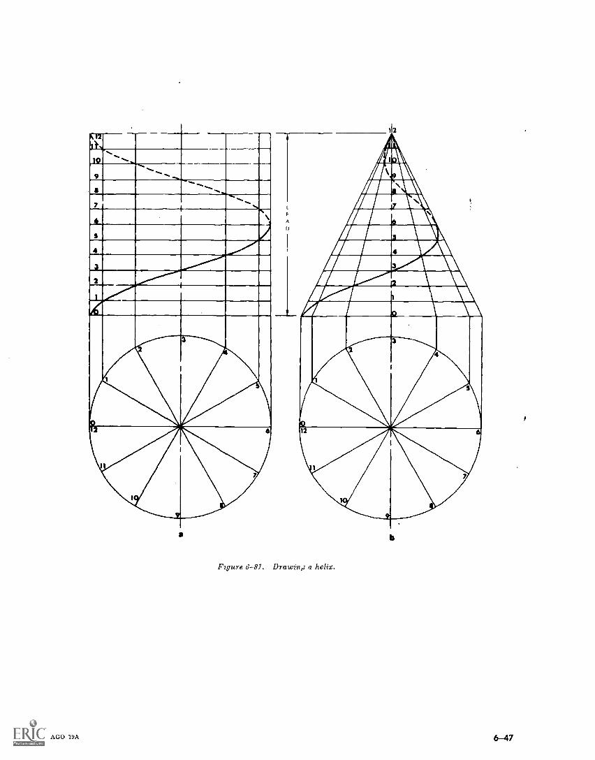
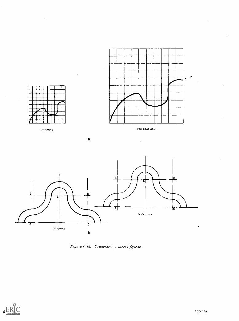
ORIGINAL
a
ENLARGEMENT
ORICLINAT
0--48
b
Figure 6-82. Transferri»g curved figures.
AGO 19A
CHAPTER 7
INTERSECTIONS AND DEVELOPMENTS
Section I. GEOMETRICAL SURFACES
7-1. Introductiona. The draftsman encounters drawings of struc-
tures which have intersecting surfaces. He mustbe able to determine the line of intersection be-tween these surfaces. He must show how thesesurfaces can be developed so that they can be fab-ricated.
b. Since most structures are bounded by geo-metric surfaces or combinations of them, thedraftsman should be familiar with the types ofsurfaces and the nomenclature.
7-2. Types of Geometrical SurfacesA surface is a geometrical magnitude having twodimensions. A geometric surface is generated bythe motion of a geometrical line, either straight orcurved, called the generatrix. Any position-of thegeneratrix is called an element of the surface. Thedirectrix is the direction in which the end or endsof the line (the generatrix) moves, or in moretechnical terms, the directrix is the line or curvewith which a generatrix of a surface remains incontact. Geometrical surfaces may be classifiedunder two broad categories : rules surfaces (para7-3) and double-curved surfaces (para 7-4).
7-3. Ruled SurfacesRuled surfaces are surfaces generated by astraight line moving according to certain rules.These can be further divided into plane, single-curved, and warped surfaces.
a. Plane. A plane surface is generated by astraight line moving so that one point touches an-other straight line as it moves parallel to its origi-nal position. Illustrated in figure 7-1 are geomet-rical solids having plane surfaces that can be un-folded and developed. These plane surfaces arecalled faces. When the faces are all regular poly-gods, the solids are called regular polyhera. Theedges of these solids are the lines of intersectionof the faces.
AGO 19A
(1) A tetrahedron is a solid bounded by 4polygonal plane surfaces that are equilateral tri-angular faces.
(2) A cube is a solid bounded by six squaresides.
(3) An octahedron is a solid bounded byeight equilateral triangles.
(4) A dodecahedron is a solid bounded bytwelve pentagons.
(5) An icosahedron is a solid bounded bytwenty equilateral triangles.
(6) A prism is a polyhedron (fig. 7-2) whosebases or ends are parallel polygons and whose lat-eral faces are parallelograms. A right prism isone whose lateral faces are squares or rectangles ;all others are called oblique prisms. The axis ofright prisms are at right angles to the bases orends. The axis of a prism is a straight line con-necting the centers of the bases. A truncatedprism is that portion of a prism lying between oneof its bases and a plane which cuts all its lateraledges.
(7) A pyramid is a polyhedron (fig. 7-3)whose base is a polygonal plane and whose othersurfaces are triangular planes meeting at a pointcalled the vertex. The 'axis is a line passingthrough the vertex and the midpoint of the base.A pyramid is right if the altitude coincides withthe axis ; it is oblique if they do not coincide. Atruncated pyramid is that portion of a pyramidlying between the base and a cutting plane notparallel to the base and cuts all the lateral edges.The frustrum of a pyramid is that portion of apyramid lying between the base and a cuttingplane parallel to the base and cuts all the lateraledges.
b. Single-Curved. A single-curved surface- isgenerated by a straight line moving in such a'manner that any two adjacent positions of thegeneratrix lie in the same plane. The followingsolids (fig. 7-4) having single-curved surfaces aredevelopable and can be unrolled to coincide with aplane.
7-1
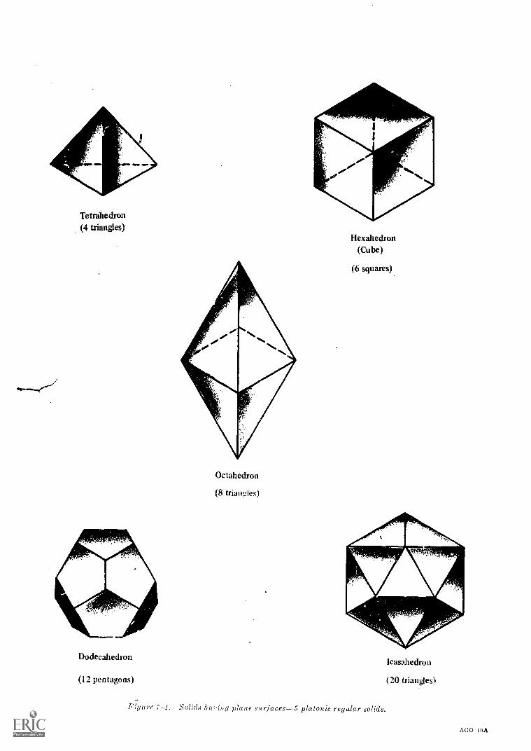
Tetrahedron4.14oneecl
Octahedron
(8 triawfles)
Dodecahedron
(12 pentagons)
Hexahedron(Cube)
(6 squares)
Figure ho log plane surfaces-5 platonic regular solids.
7-2
Icasahedron
(20 triangles)
AGO 19A
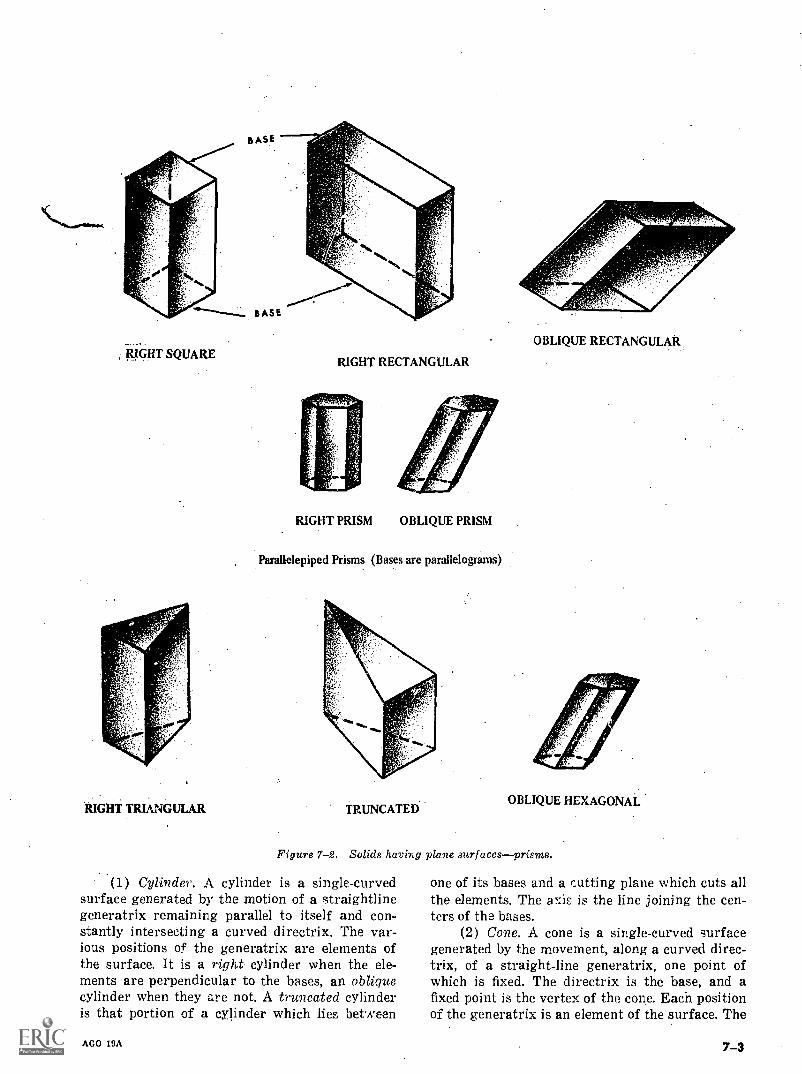
RIGHT SQUARE
RIGHT TRIANGULAR
RIGHT RECTANGULAR
RIGHT PRISM OBLIQUE PRISM
Parallelepiped Prisms (Bases are parallelograms)
TRUNCATED
OBLIQUE RECTANGULAR
OBLIQUE HEXAGONAL
Figure 7-2. Solids having plane surfacesprisms.
(1) Cylinder. A cylinder is a single-curvedsurface generated by the motion of a straightlinegeneratrix remaining parallel to itself and con-stantly intersecting a curved directrix. The var-ious positions of the generatrix are elements ofthe surface. It is a right cylinder when the ele-ments are perpendicular to the bases, an obliquecylinder when they are not. A truncated cylinderis that portion of a cylinder which lies between
AGO 19A
one of its bases and a cutting plane which cuts allthe elements. The axis is the line joining the cen-ters of the bases.
(2) Cone. A cone is a single-curved surfacegenerated by the movement, along a curved direc-trix, of a straight-line generatrix, one point ofwhich is fixed. The directrix is the base, and afixed point is the vertex of the cone. Each positionof the generatrix is an element of the surface. The
7-3
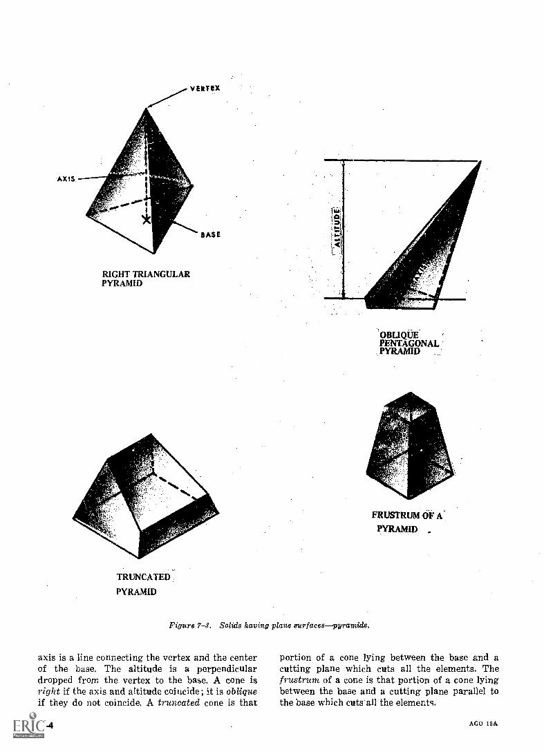
'AXIS
VERTEX
RIGHT TRIANGULARPYRAMID
BASE
TRUNCATED
PYRAMID
OBLIQUEPENTAGONALPYRAMID
Figure 7-4. Solids having plane surfacespyramids.
axis is a line connecting the vertex and the centerof the base. The altitude is a perpendiculardropped from the vertex to the base. A cone isright if the axis and attitude coincide; it is obliqueif they do not coincide. A truncated cone is that
7-4
FRUSTRUM OF A.
PYRAMID ...
portion of a cone lying between the base and acutting plane which cuts all the elements. Thefrustrum of a cone is that portion of a cone lyingbetween the base and a cutting plane parallel tothe base which cuts all the elements.
AGO 19A
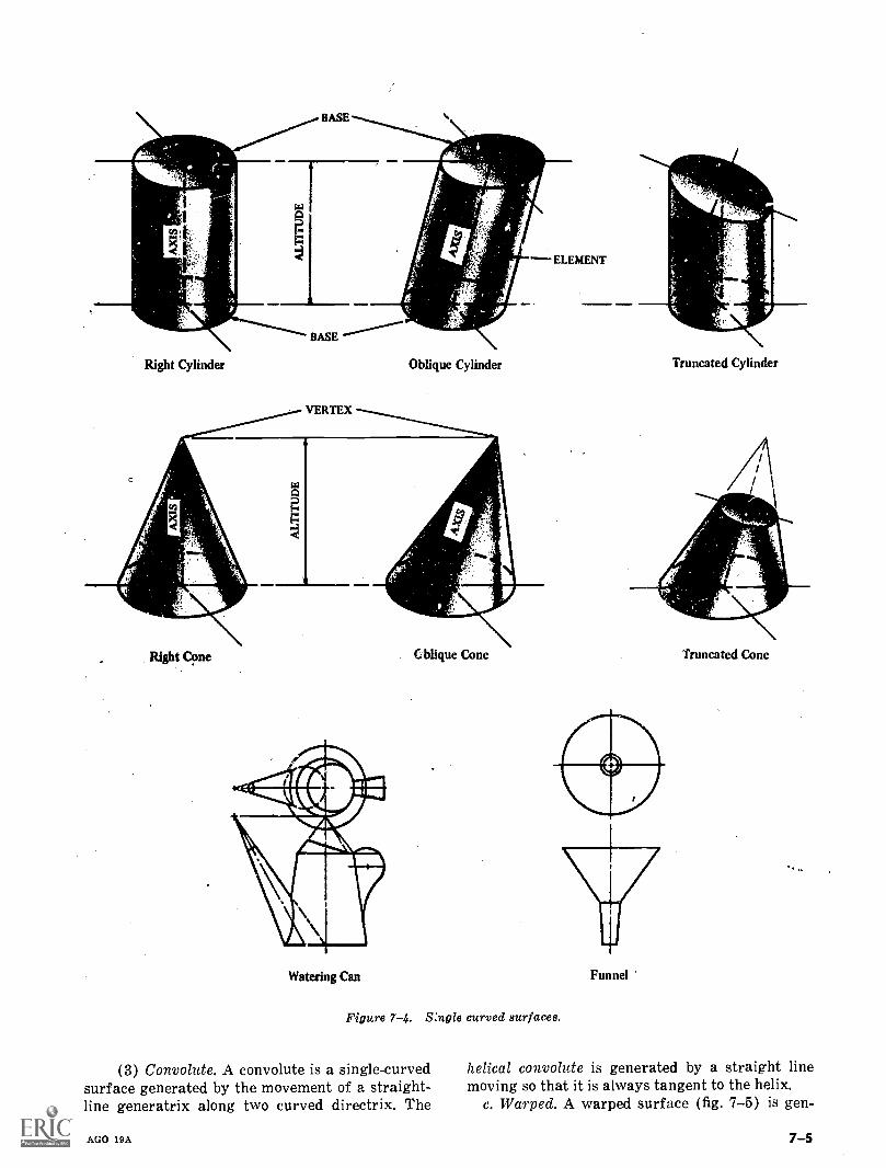
Right Cylinder Oblique Cylinder
Right Cone blique Cone
Watering Can
Truncated Cylinder
Truncated Cone
Figure 7-4. Single curved surfaces.
(3) Convolute. A convolute is a single-curvedsurface generated by the movement of a straight-line generatrix along two curved directrix. The
AGO 19A
Funnel
helical convolute is generated by a straight linemoving so that it is always tangent to the helix.
c. Warped. A warped surface (fig. 7-5) is gen-
7-5
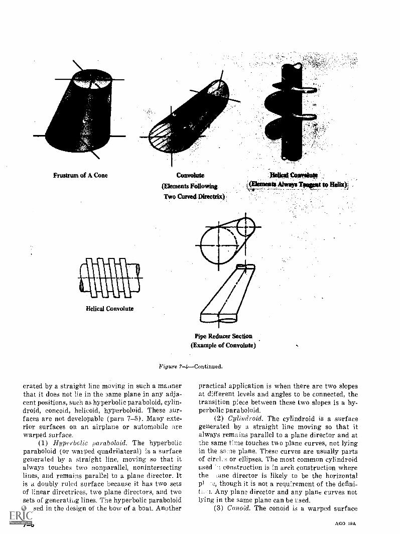
Frustrum of A Cone
Helical Convolute
Convolute
(Elements Following
Two Curved Directrix)
DOW Con VAInte.
(Dements Always Tongs* to Helix
Pipe Reducer Section(Example of Convolute)
Figure 7-4Continued.
erated by a straight line moving in such a matinerthat it does not He in the same plane in any adja-cent positions, such as hyperbolic paraboloid, cylin-droid, concoid, helicoid, hyperboloid. These sur-faces are not developable (para 7-5). Many exte-rior surfaces on an airplane or automobile arewarped surface.
(1) Hyperbolic paraboloid. The hyperbolicparaboloid (or warped quadrilateral) is a surfacegenerated by a straight line, moving so that italways touches two nonparallel, nonintersectinglines, and remains parallel to a plane director. Itis a doubly ruled surface because it has two setsof linear directrices, two plane directors, and twosets of generating lines. The hyperbolic paraboloidis used in the design of the bow of a boat. Another
7-6
practical application is when there are two slopesat different levels and angles to be connected, thetransition piece between these two slopes is a hy-perbolic paraboloid.
(2) Cylindroid. The cylindroid is a surfacegenerated by a straight line moving so that italways remains parallel to a plane director and atthe same tine touches two plane curves, not lyingin the sa lie plane. These curves are usually partsof circi, s or ellipses. The most common cylindroidused '.1 construction is in arch construction wherethe lane director is likely to be the horizontalpl te, though it is not a requirement of the defini-t. ii. Any plane director and any plane curves notlying in the same plane can be u.sed.
(3) Conoid. The conoid is a warped surface
AGO 19A
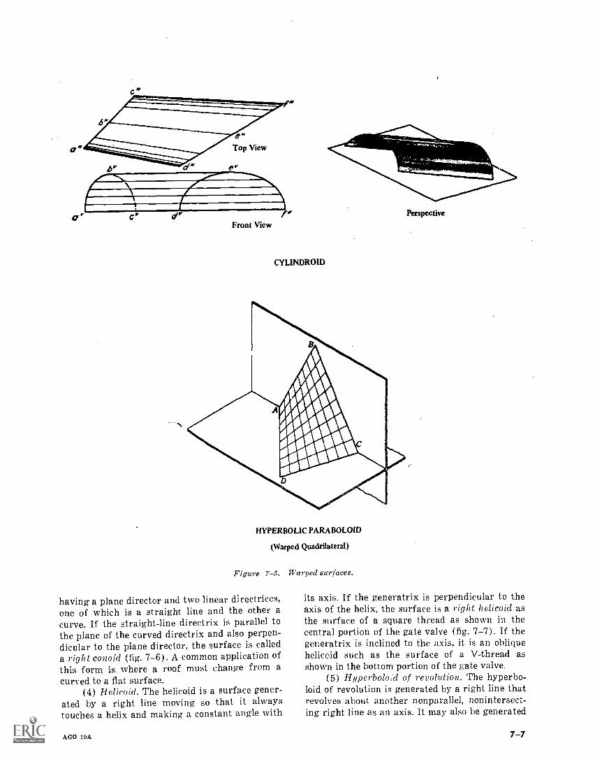
Front View
CYLINDROID
HYPERBOLIC PARABOLOID
(Warped Quadrilateral)
Figure 7-5. Warped surfaces.
having a plane director and two linear directrices,one of which is a straight line and the other acurve. If the straight-line directrix is parallel tothe plane of the curved directrix and also perpen-dicular to the plane director, the surface is calleda right conoid (fig. 7-6). A common application ofthis form is where a roof must change from acurved to a flat surface.
(4) Helicoid. The helicoid is a surface gener-ated by a right line moving so that it alwaystouches a helix and making a constant angle with
AGO 19A
Perspective
its axis. If the generatrix is perpendicular to theaxis of the helix, the surface is a right helicoid asthe surface of a square thread as shown in thecentral portion of the gate valve (fig. 7-7). If thegeneratrix is inclined to the axis, it is an obliquehelicoid such as the surface of a V-thread asshown in the bottom portion of the gate valve.
(5) Hyperbole id of revolution. The hyperbo-loid of revolution is generated by a right line thatrevolves about another nonparallel, nonintersect-ing right line as an axis. It may also be generated
7-7
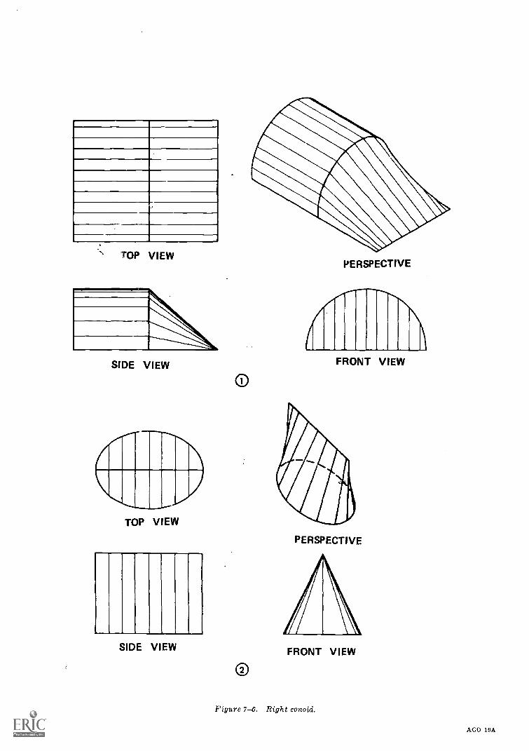
TO
P
VIE
W
SID
E
VIE
W
TO
P
VIE
W
SID
E
VIE
W
7-8
PE
RS
PE
CT
IVE
FR
ON
T
VIE
W
PE
RS
PE
CT
IVE
FR
ON
T
VIE
W
Figu
re
7-6.
Rig
ht
cono
id.
AG
O
19A
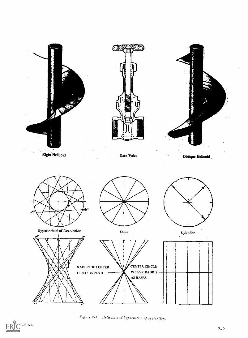
Right Helicoid
Hyperboloid of RevolutioncrY OW
AGO 19A
Gate Valve
Cone
CENTEROF CENTER CIRCLECIR LE
IS SAME RADIUSCIRCLE IS ZERO.
Oblique Helicoid
Cylinder
Figure 7-7. Helicoid and hyperboloid of revolution.
7 -9
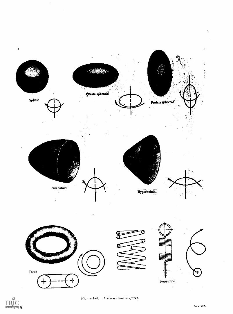
Paraboloid
Oblate
yPetboloid--
Figure 7-8. Double-curved aurfacea.
7 -10
Serpentine
AGO 10A
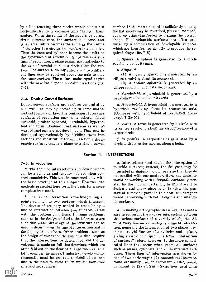
by a line touching three circles whose planes areperpendicular to a common axis through theircenters. When the radius of the middle, or gorge,circle becomes zero, the surface is a cone, andwhen this radius becomes the same as the radiusof the other two circles, the surface is a cylinder.Thus the cone and cylinder become the limits ofthe hyperboloid of revolution. Since this is a sur-face of revolution, a plane passed perpendicular tothe axis of revolution cuts a circle from the sur-face. The surface is doubly ruled since two differ-ent lines may be revolved about the axis to givethe same surface. These lines make equal angleswith the base but slope in opposite directions (fig.7-7).
7-4. Double Curved SurfacesDouble curved surfaces are surfaces generated bya curved line moving according to some mathe-matical formula or law. The commonest forms aresurfaces of revolution such as a sphere, oblatespheroid, prolate spheroid, paraboloid, hyperbo-loid and torus. Double-curved surfaces as well aswarped surfaces are not developable. They may bedeveloped appr'iximately by dividing them intosections and substituting for each section a devel-opable surface ; that is a plane or a single-curved
Section II.
7-5. Introductiona. The topic of intersections and developments
can be a complex and lenghty subject when cov-ered completely. This text is concerned only withthe basic coverage of this subject. However, themethods presented here form the basis for a morecomplete treatment.
b. The line of intersection is the line joining allpoints common to two surfaces which intersect.The degree of accuracy needed in establishing aline of intersection between two surfaces varieswith the problem conditions. In some problems,such as in the design of ducts, the tolerances aresuch that scaled drawings of the structure can beused in determ; -'ng the line of intersection and indeveloping the surfaces. Other problems, such asthe design of plates for the hull of a ship, requirethat the intersections be determined and the de-velopments made on full-size drawings which areoften laid wit on the floor of a large room called aloft room. In the aircraft industry, developmentsfrequently must be accurate to 0.005 of an inchdue to the need to avoid turbulent air flow overintersecting surfaces.
AGO 19A
surface. If the material used is sufficiently pliable,the flat sheets may be stretched, pressed, stamped,spun, or otherwise forced to assume the desireushape. Nondevelopable surfaces are often pro-duced by a combination of developable surfaceswhich are then formed slightly to produce the re-quired shape (fig. 7-8).
a. Sphere. A sphere is generated by a circlerevolving about its axis.
b. Ellipsoid.(1) An oblate spheroid is generated by an
ellipse revolving about its minor axis.(2) A prolate spheroid is generated by an
ellipse revolving about its major axis.
c. Paraboloid. A paraboloid is generated by aparabola revolving about its axis.
d. Hyperboloid. A hyperboloid is generated by ahyperbola revolving about its transverse axis.(Compare with hyperboloid of revolution, para-graph 7-3c(5)).
e. Torus. A torus is generated by a circle withits center revolving along the circumference of alarger circle.
f. Serpentine. A serpentine is generated by acircle with its center moving along a helix.
INTERSECTIONS
c. Intersections need not be the intersection oftangible surfaces; instead, the designer may beinterested in shaping moving parts so that they donot conflict with one another. Here, the designerwould be working with intangible surfaces gener-ated by the moving parts. Or, he might want todesign a stationary piece so as to allow the pas-sage of a moving part ; in this case, the designerwould be working with both tangible and intangi-ble surfaces.
d. In making orthographic drawings, it is neces-sary to represent the lines of intersection betweenthe various surfaces of a variety of objects. Al-most every line on a drawing is a line of intersec-tion, generally the intersection of two planes, giv-ing a straight line, or of a cylinder and a plane,giving a circle or ellipse. The term "intersectionof surfaces" refers, however, to the more compli-cated lines that occur when geometric surfacessuch as planes, cylinders, and cones intersect eachother. These lines of intersection are shown byone of two basic ways: (1) conventional intersec-tions, ordinarily used to represent a fillet, round,or runout, or (2) plotted intersections, used when
7 -11
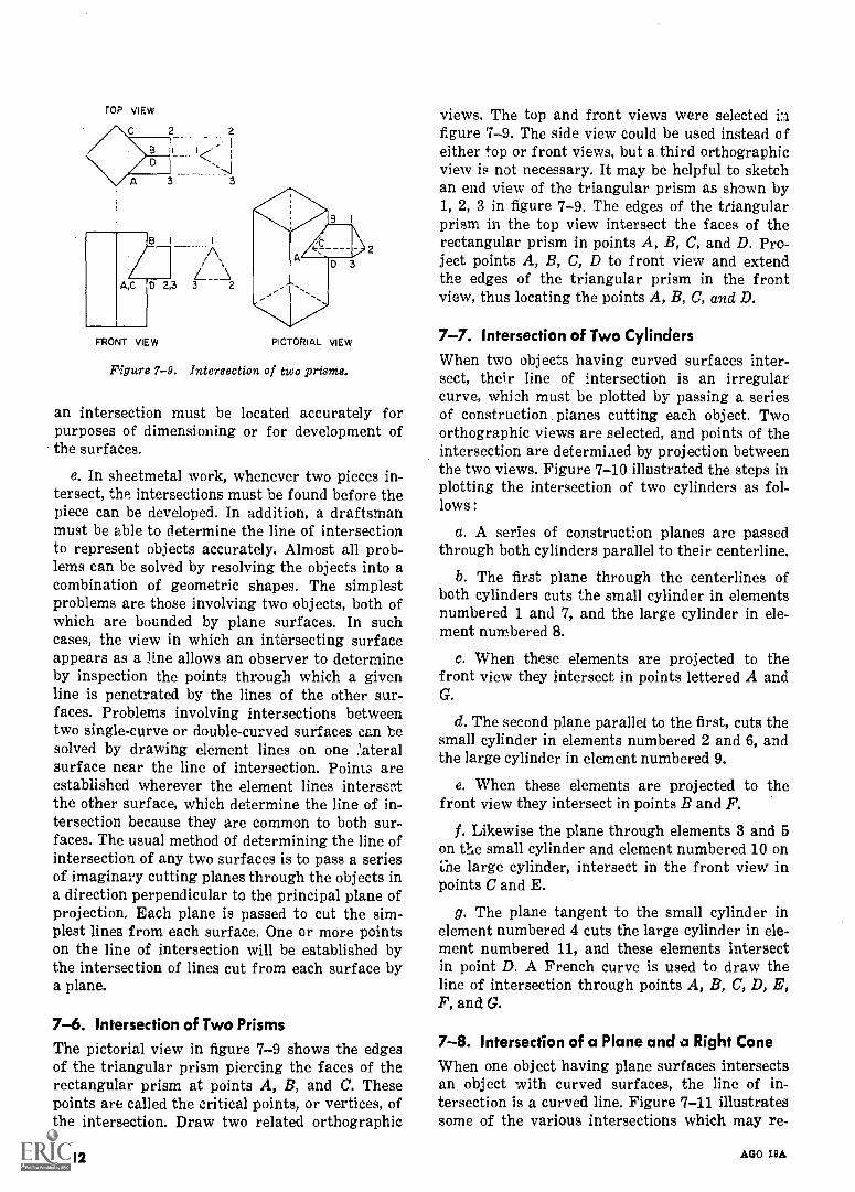
FRONT VIEW PICTORIAL VIEW
Figure 7-9. Intersection of two prisms.
an intersection must be located accurately forpurposes of dimensioning or for development ofthe surfaces.
e. In sheetmetal work, whenever two pieces in-tersect, the intersections must be found before thepiece can be developed. In addition, a draftsmanmust be able to determine the line of intersectionto represent objects accurately. Almost all prob-lems can be solved by resolving the objects into acombination of geometric shapes. The simplestproblems are those involving two objects, both ofwhich are bounded by plane surfaces. In suchcases, the view in which an intersecting surfaceappears as a line allows an observer to determineby inspection the points through which a givenline is penetrated by the lines of the other sur-faces. Problems involving intersections betweentwo single-curve or double-curved surfaces can besolved by drawing element lines on one .'ateralsurface near the line of intersection. Points areestablished wherever the element lines intersectthe other surface, which determine the line of in-tersection because they are common to both sur-faces. The usual method of determining the line ofintersection of any two surfaces is to pass a seriesof imaginary cutting planes through the objects ina direction perpendicular to the principal plane ofprojection. Each plane is passed to cut the sim-plest lines from each surface. One or more pointson the line of intersection will be established bythe intersection of lines cut from each surface bya plane.
7-6. Intersection of Two PrismsThe pictorial view in figure 7-9 shows the edgesof the triangular prism piercing the faces of therectangular prism at points A, B, and C. Thesepoints are called the critical points, or vertices, ofthe intersection. Draw two related orthographic
7 -1T
views. The top and front views were selected infigure 7-9. The side view could be used instead ofeither top or front views, but a third orthographicview is not necessary. It may be helpful to sketchan end view of the triangular prism as shown by1, 2, 3 in figure 7-9. The edges of the triangularprism in the top view intersect the faces of therectangular prism in points A, B, C, and D. Pro-ject points A, B, C, D to front view and extendthe edges of the triangular prism in the frontview, thus locating the points A, B, C, and D.
7-7. Intersection of Two CylindersWhen two objects having curved surfaces inter-sect, their line of intersection is an irregularcurve, which must be plotted by passing a seriesof construction planes cutting each object. Twoorthographic views are selected, and points of theintersection are determiaed by projection betweenthe two views. Figure 7-10 illustrated the steps inplotting the intersection of two cylinders as fol-lows :
a. A series of construction planes are passedthrough both cylinders parallel to their centerline.
b. The first plane through the centerlines ofboth cylinders cuts the small cylinder in elementsnumbered 1 and 7, and the large cylinder in ele-ment numbered 8.
c. When these elements are projected to thefront view they intersect in points lettered A andG.
d. The second plane parallel to the first, cuts thesmall cylinder in elements numbered 2 and 6, andthe large cylinder in element numbered 9.
e. When these elements are projected to thefront view they intersect in points B and F.
f. Likewise the plane through elements 3 and 5on the small cylinder and element numbered 10 onthe large cylinder, intersect in the front view inpoints C and E.
g. The plane tangent to the small cylinder inelement numbered 4 cuts the large cylinder in ele-ment numbered 11, and these elements intersectin point D. A French curve is used to draw theline of intersection through points A, B, C, D, E,F, and 0.
7-8. Intersection of a Plane and a Right CaneWhen one object having plane surfaces intersectsan object with curved surfaces, the line of in-tersection is a curved line. Figure 7-11 illustratessome of the various intersections which may re-
AGO 19A
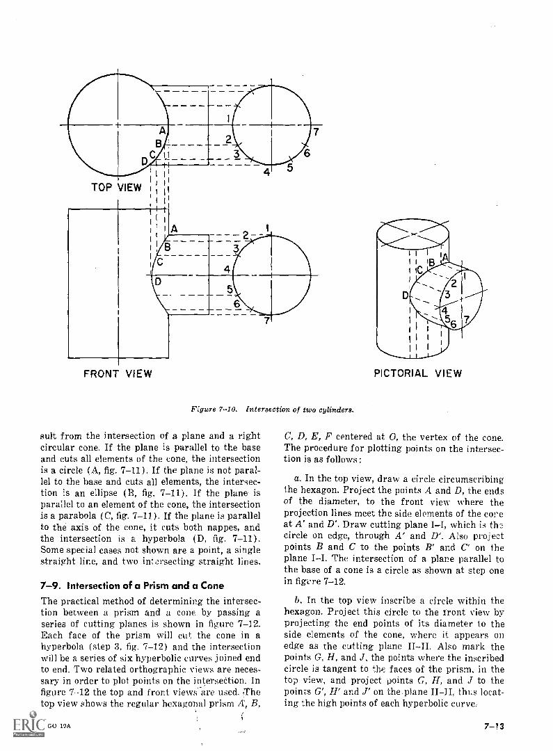
1
TOP VIEW
t
e.
C
A
B
FRONT VIEW
6
Figure 7-10. Intersection of two cylinders.
suit from the intersection of a plane and a rightcircular cone. If the plane is parallel to the baseand cuts all elements of the cone, the intersectionis a circle (A, fig. 7-11). If the plane is not paral-lel to the base and cuts all elements, the intersec-tion is an ellipse (B, fig, 7-11). If the plane isparallel to an element of the cone, the intersectionis a parabola (C, fig. 7-11). If the plane is parallelto the axis of the cone, it cuts both nappes, andthe intersection is a hyperbola (D, fig. 7-11).Some special cases not shown are a point, a singlestraight line, and two intersecting straight lines.
7-9. Intersection of a Prism and a Cone
The practical method of determining the intersec-tion between a prism and a cone by passing aseries of cutting planes is shown in figure 7-12.Each face of the prism will cut the cone in ahyperbola (step 3, fig. 7-12) and the intersectionwill be a series of six hyperbolic curves joined endto end. Two related orthographic views are neces-sary in order to plot points on the intersection. Infigure 7-12 the top and front views are used. ,Thetop view shows the regular hexagonal prism A`i B,
AGO 19A
PICTORIAL VIEW
C, D, E, F centered at 0, the vertex of the cone.The procedure for plotting points on the intersec-tion is as follows:
a. In the top view, draw a circle circumscribingthe hexagon. Project the points A and D, the endsof the diameter, to the front view where theprojection lines meet the side elements of the coreat A' and D'. Draw cutting plane II, which is thecircle on edge, through A' and D'. Also projectpoints B and C to the points B' and C' on theplane II. The intersection of a plane parallel tothe base of a cone is a circle as shown at step onein figure 7-12.
b. In the top view inscribe a circle within thehexagon. Project this circle to the tront view byprojecting the end points of its diameter to theside elements of the cone, where it appears onedge as the cutting plane IIII. Also mark thepoints G, H, and J. the points where the inscribedcircle is tangent to the faces of the prism, in thetop view, and project points G, H, and J to thepoints G', H' and J' on the-plane IIII, thus locat-ing the high points of each hyperbolic curve.
7-13
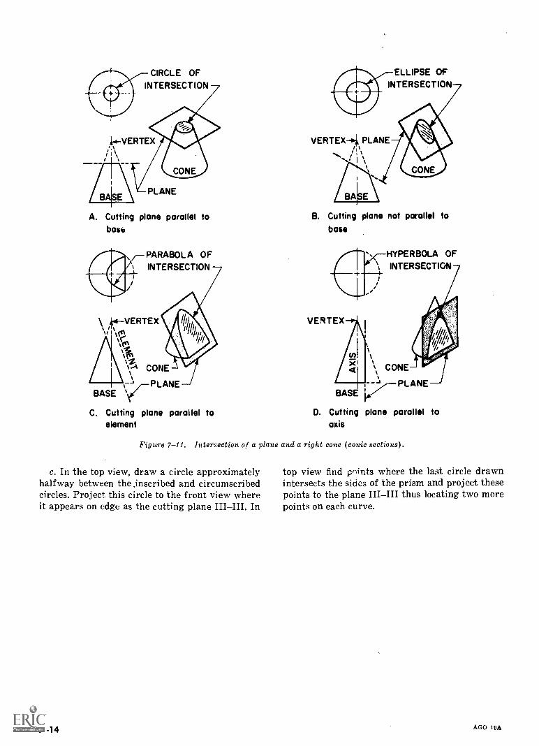
CIRCLE OFINTERSECTION
A. Cutting plane parallel tobash
PARABOLA OFINTERSECTION
\ 4VERTEX
-% PLANEBASE
CONE
C. Cutting plane parallel toelement
ELLIPSE OFINTERSECTION
B. Cutting plane not parallel tobase
HYPERBOLA OFINTERSECTION
D. Cutting plane parallel toaxis
Figure 7-11. Intersection of a plane and a right cone (conic sections).
c. In the top view, draw a circle approximatelyhalfway between the .inscribed and circumscribedcircles. Project this circle to the front view whereit appears on edge as the cutting plane In
7-14
top view find prints where the last circle drawnintersects the sides of the prism and project thesepoints to the plane thus locating two morepoints on each curve.
AGO 19A
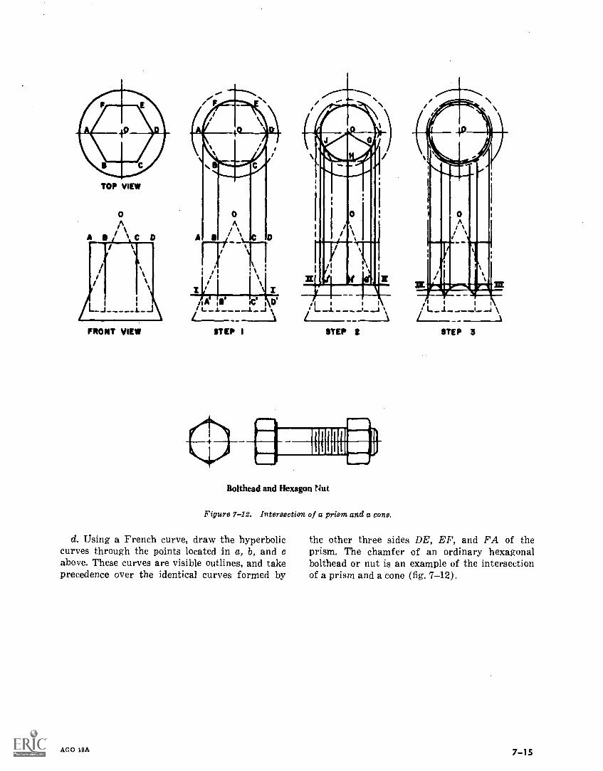
TOP VIEW
0A/
A C
FRONT VIEW
0
A
I1 II/ I/ 11 \ ' a (ft xI %i ' r 1---..--
11 AI Ile le 1 DI/ L ....1................./.........1 tt _
i_______
/I9 I
STEP I STEP 2
Bolthead and Hexagon Nut
Figure 7-12. Intersection of a prism and a cone.
d. Using a French curve, draw the hyperboliccurves through the points located in a, b, and cabove. These curves are visible outlines, and takeprecedence over the identical curves formed by
AGO 19A
I I I
1-_17 _77._ 7.1
STEP 3
the other three sides DE, EF, and FA of theprism. The chamfer of an ordinary hexagonalbolthead or nut is an example of the intersectionof a prism and a cone (fig. 7-12).
7-15
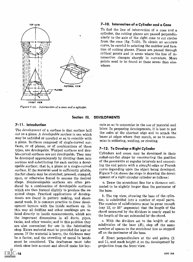
FRONT VIEW
1/2
PLANES
PICTORIAL VIEW
Figure 7-13. Intersection of a carte and a cylinder.
Section
7-11. IntroductionThe development of a surface is that surface laidout on a plane. A developable surface is one whichmay be unfolded or unrolled so as to coincide witha plane. Surfaces composed of single-curved sur-faces, or of planes, or of combinations of thesetypes, are developable. Warped surfaces and dou-ble-curved surfaces are not developable. They maybe developed approximately by dividing them intosections and substituting for each section a devel-opable surface ; that is, a plane or a single-curvedsurface. If the material used is sufficiently pliable,the flat sheets may be stretched, pressed, stamped,spun, or otherwise forced to assume the desiredshape. Nondevelopable surfaces are often pro-duced by a combination of developable surfaceswhich are then formed slightly to produce the re-quired shape. Practical applications of develop-ments are found in pattern making, and sheet-metal work. It is common practice to draw devel-opment layouts with the inside surfaces up. Inthis way all foldline and other markings are re-lated directly to inside measurements, which arethe important dimensions in all ducts, pipes,tanks, and other vessels; and in this position theyare also convenient for use in the fabricatingshop. Extra material must be provided for laps orseams. If the material is hewry, the thickness maybe a factor, and the crowding of metal in bendsmust be considered. The draftsman must takestock sizes into account and should make his lay-
7-16.
7-10. Intersection of a Cylinder and a Cone
To find the line of intersection of a cone and acylinder, the cutting planes are passed perpendic-ularly to the axis of the fight cone to cut circlesfrom the cone (fig. 7-13). To obtain an accuratecurve, be careful in selecting the number and loca-tion of cutting planes. Planes are passed throughcritical points and in areas where the line of in-tersection changes sharply in curvature. Morepoints need to be found at these areas than else-where.
DEVELOPMENTS
outs so as to economize in the use of material andlabor. In preparing developments, it is best to putthe seam at the shortest edge and to attach thebases at edges where they match, so as to econo-mize in soldering, welding, or riveting.
7-12. To Develop a Right CylinderCylinders and cones may be developed in theirrolled-out-flat shape by constructing the positionof the generatrix at regular intervals and connect-ing the end points with a straight-edge or Frenchcurve depending upon the object being developed.Figure 7-14 shows the steps in drawing the devel-opment of a right circular cylinder as follows:
a. Draw the stretchout line for a distance esti-mated to be slightly longer than the perimeter ofthe base.
b. The top view, showing the base of the cylin-der, is subdivided into a number of equal parts.The number of subdivisions must be great enough(say 12, or 30° segments) that the length of thechord measured by the dividers is nearly equal tothe length of the arc subtended by the chord.
c. With the dividers set to the length of onesubdivision of the base (B), step off the samenumber of spaces in the stretchout line as steppedoff on the perimeter of the base.
d. Erect perpendiculars at the end points (1and 1), and mark height A on the development byprojection from the front view.
AGO 19A
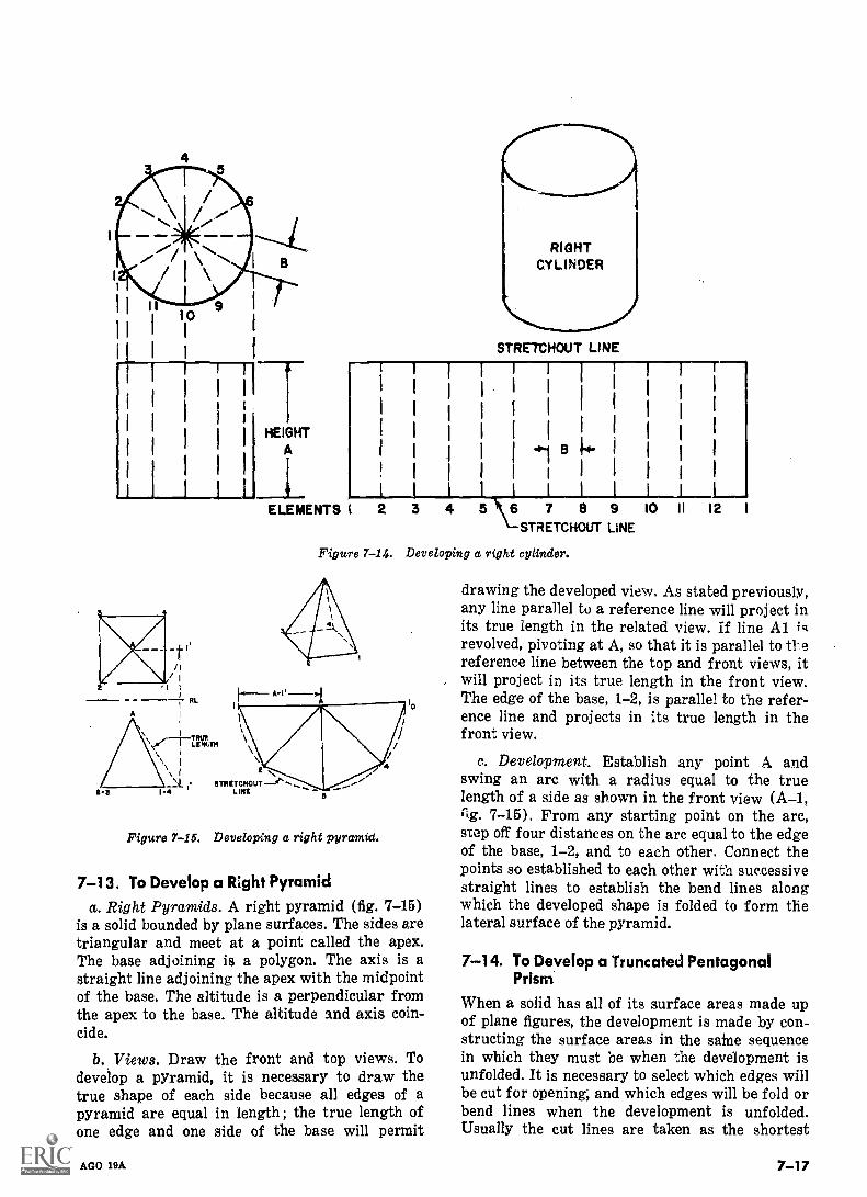
I I 11 10
I I I
I
1
1
STRETCHOUT LINE
HEIGHTA
ELEMENTS I 6 7 8 9 10 II 12
STRETCHOUT LINE
Figure 7-14. Developing a right cylinder.
2-3
,II.`4.
1-4STRETCHOUT
LINE
Figure 7-15. Developing a right pyramid.
7-13. To Develop a Right Pyramida. Right Pyramids. A right pyramid (fig. 7-15)
is a solid bounded by plane surfaces. The sides aretriangular and meet at a point called the apex.The base adjoining is a polygon. The axis is astraight line adjoining the apex with the midpointof the base. The altitude is a perpendicular fromthe apex to the base. The altitude and axis coin-cide.
b. Views. Draw the front and top views. Todevelop a pyramid, it is necessary to draw thetrue shape of each side because all edges of apyramid are equal in length ; the true length ofone edge and one side of the base will permit
AGO 19A
drawing the developed view. As stated previously,any line parallel to a reference line will project inits true length in the related view. If line Al iqrevolved, pivoting at A, so that it is parallel to tl'ereference line between the top and front views, itwill project in its true length in the front view.The edge of the base, 1-2, is parallel to the refer-ence line and projects in its true length in thefront view.
c. Development. Establish any point A andswing an arc with a radius equal to the truelength of a side as shown in the front view (A-1,rig. 7-15). From any starting point on the arc,step off four distances on the arc equal to the edgeof the base, 1-2, and to each other. Connect thepoints so established to each other with successivestraight lines to establish the bend lines alongwhich the developed shape is folded to form thelateral surface of the pyramid.
7-14. To Develop a Truncated PentagonalPrism
When a solid has all of its surface areas made upof plane figures, the development is made by con-structing the surface areas in the same sequencein which they must be when the development isunfolded. It is necessary to select which edges willbe cut for opening; and which edges will be fold orbend lines when the development is unfolded.Usually the cut lines are taken as the shortest
7-17
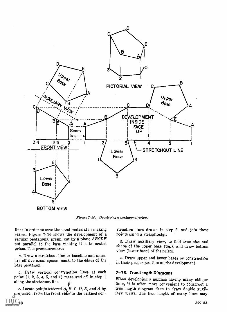
314 2 5FRONT VIEW
2
LowerBase
5
BOTTOM VIEW
2
2
PICTORIAL VIEW
I
DEVELOPMENTINSIDE
FACE r
UP I
LowerBase
UPPerease
E
4 5
STRETCHOUT LINE
Figure 7-16. Developing a pentagonal prim.
lines in order to save time and material in makingseams. Figure 7-16 shows the development of aregular pentagonal prism, cut by a plane ABCDEnot parallel to the base making it a truncatedprism. The procedures are :
a. Draw a stretchout line or baseline and meas-ure off five equal spaces, equal to the edges of thebase pentagon.
b. Draw vertical construction lines at eachpoint (1, 2, 3, 4, 5, and 1) measured off in step 1along the stretchout line.
c. Locate points letteredA
C, D, E, and A byprojection froin the front via to the vertical con-
7-18
struction lines drawn in step 2, and join thesepoints using a straightedge.
d. Draw auxiliary view, to find true size andshape of the upper base (top), and draw bottomview (lower base) of the prism.
e. Draw upper and lower bases by constructionin their proper position on the development.
7-15. True-Length Diagrams
When developing a surface having many obliquelines, it is of ten more convenient to construct atrue-length diagram than to draw double auxil-iary views. The true length of many lines may
AGO 19A
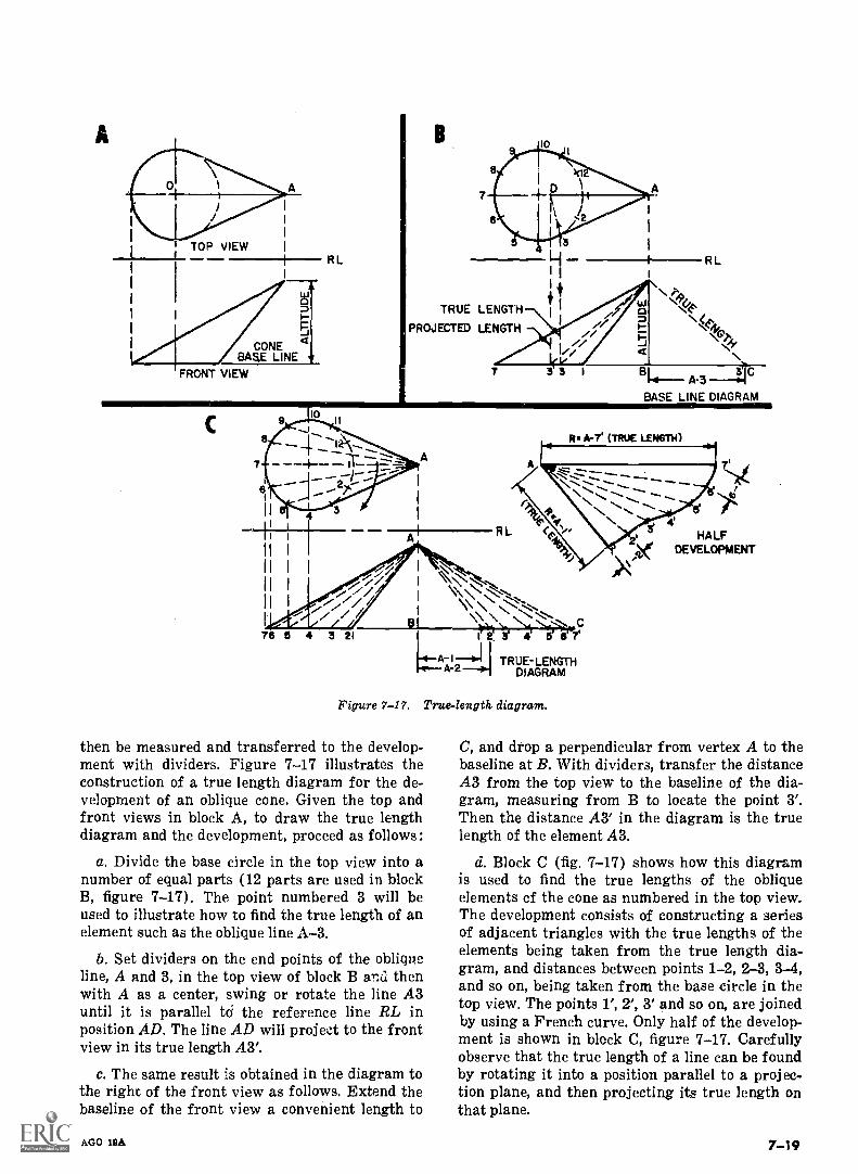
A
TOP VIEWRL RL
TRUE LENGTH
PROJECTED LENGTH
3A-3
BASE LINE DIAGRAM
Re A-7 (TRUE LENGTH)
76 6 4 3 21
\\0.1_1 N
c\\
1 2. 3 4 6 67'A-4.1T-01 TRUE-LENGTH
DIAGRAM
Figure 7-17. True-length. diagram.
then be measured and transferred to the develop-ment with dividers. Figure 7-17 illustrates theconstruction of a true length diagram for the de-velopment of an oblique cone. Given the top andfront views in block A, to draw the true lengthdiagram and the development, proceed as follows:
a. Divide the base circle in the top view into anumber of equal parts (12 parts are used in blockB, figure 7-17). The point numbered 3 will beused to illustrate how to find the true length of anelement such as the oblique line A-3.
b. Set dividers on the end points of the obliqueline, A and 3, in the top view of block B anzi thenwith A as a center, swing or rotate the line A3until it is parallel td the reference line RL inposition AD. The line AD will project to the frontview in its true length A3'.
c. The same result is obtained in the diagram tothe right of the front view as follows. Extend thebaseline of the front view a convenient length to
AGO 11dA
HALFDEVELOPMENT
C, and drop a perpendicular from vertex A to thebaseline at B. With dividers, transfer the distanceA3 from the top view to the baseline of the dia-gram, measuring from B to locate the point 3'.Then the distance A3' in the diagram is the truelength of the element A3.
d. Block C (fig. 7-17) shows how this diagramis used to find the true lengths of the obliqueelements cf the cone as numbered in the top view.The development consists of constructing a seriesof adjacent triangles with the true lengths of theelements being taken from the true length dia-gram, and distances between points 1-2, 2-3, 3-4,and so on, being taken from the base circle in thetop view. The points 1', 2', 3' and so on, are joinedby using a French curve. Only half of the develop-ment is shown in block C, figure 7-17. Carefullyobserve that the true length of a line can be foundby rotating it into a position parallel to a projec-tion plane, and then projecting its true length onthat plane.
7 -19
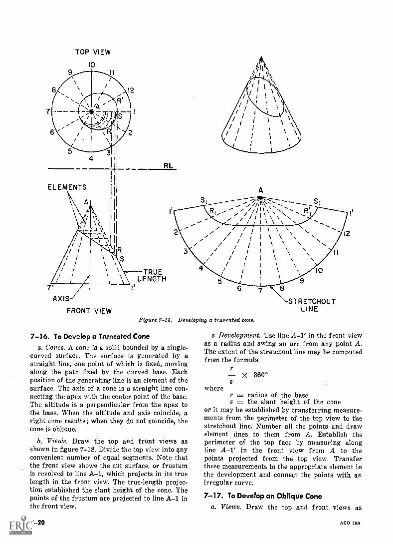
TOP VIEW
10
ELEMENTS
A
\
7'AXIS
FRONT VIEW
RL
TRUELENGTH
AJortz...z-
//in \\N/
\11 \ ,
Figure 7-18. Developing; a truncated cone.
7-16. To Develop a Truncated Cone
a. Cones. A cone is a solid bounded by a single-curved surface. The surface is generated by astraight line, one point of which is fixed, movingalong the path fixed by the curved base. Eachposition of the generating line is an element of thesurface. The axis of a cone is a straight line con-necting the apex with the center point of the base.The altitude is a perpendicular from the apex tothe base. When the altitude and axis coincide, aright cone results; when they do not coincide, thecone is oblique.
b. VieWs. Draw the top and front views asshown in figure 7-18. Divide the top view into anyconvenient number of equal segments. Note thatthe front view shows the cut surface, or frustumis revolved to line A-1, which projects in its truelength in the front view. The true-length projec-tion established the slant height of the cone. Thepoints of the frustum are projected to line A-1 inthe front view.
7-20
STRETCHOUTLINE
c. Development. Use line A-1' in the front viewas a radius and swing an arc from any point A.The extent of the stretchout line may be computedfrom the formula
7X 360°
wherer radius of the bases the slant height of the cone
or it may be established by transferring measure-ments from the perimeter of the top view to thestretchout line. Number all the points and drawelement lines to them from A. Establish theperimeter of the top face by measuring alongline A-1' in the front view from A to thepoints projected from the top view. Transferthese measurements to the appropriate element inthe development and connect the points with anirregular curve.
7-17. To Develop an Oblique Cone
a. Views. Draw the top and front views as
AGO 19A
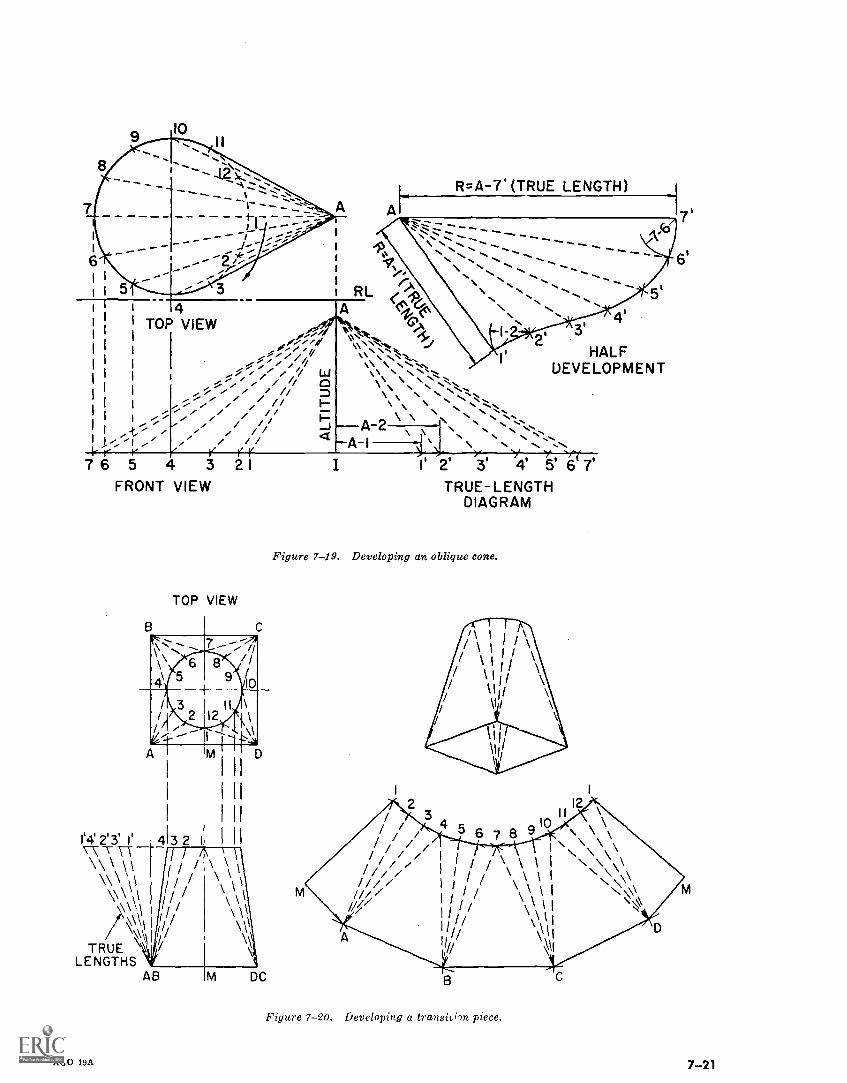
R=A-7' (TRUE LENGTH)
`.....
RL ( C#,PI 4 A 0;1_6
,,-,4(6i TOP VIEW %.,-,
I ...,,,,d'':414 l'I`\`.b.\a.....:;<:"..-
if..." %,
I ..., / / / ,... \ .,........" ./... // , / /
I / / / / //..... ...' / / / ,
I ... .., ..., .." / , '". / / / /
I /; / ./ /.., ./ /, ' ./
./ / / /k
, 1 ..' . .(/ii/
r r / r76 5 4 3 2I
FRONT VIEW
TOP VIEW
B C
/I
\
\ 65
/ 3/ 2
4-
1'4 2'3' 413 2 I
-7\ \\ \I
7\\\ \\\\\\/\\\\
\\\\\\\ITRUE \
LENGTHS
89 0
AGO 19A
N....N.....s \ .... \ Ns \ ' ... \ N \\ \ \ ' N ....N. N....,\ \A 2 . . %.-
I :2' 3'
Y I is fr7'
. . , \ \ Ns.\ NA I . . N. N. N
I 2 3 4 5 6 7TRUE- LENGTH
DIAGRAM
HALFDEVELOPMENT
Figure 7-19. Developing an oblique cone.
Figure 7-20. Developing a transii6it piece.
7-21
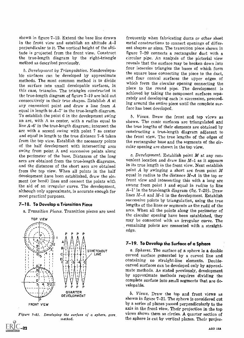
shown in figure 7-19. Extend the base line drawnin the front view and establish an altitude AIperpendicular to it. The vertical height of the alti-tude is projected from the front view. Constructthe true-length diagram by the right-trianglemethod as described previously.
b. Development by Triangulation. Nondevelopa-ble surfaces can he developed by approximatemethods. The most common method is to dividethe surface into small developable surfaces, inthis case, triangles. The triangles constructed inthe true-length diagram of figure 7-19 are laid outconsecutively in their true shapes. Establish A atany convenient point and draw a line from Aequal in length to A-7' in the true-length diagram.To establish the point 6 in the development swingan arc, with A as center, with a radius equal toline A-6' in the true-length diagram; intersect thearc with a second swing with point 7 as centerand equal in length to the true distance 7-6 takenfrom the top view. Establish the necessary pointsof the half development with intersecting arcsswing from point A and successive points alongthe perimeter of the base. Distances of the longarcs are obtained from the true-length diagrams,and the distances of the short arcs are obtainedfrom the top view. When al] points in the halfdevelopment have been established, draw the ele-ment (or bend) lines and connect the points withthe aid of an irregular curve. The development,although only approximate, is accurate enough formost practical purposes.
7-18. To Develop a Transition Piecea. Transition Pieces. Transition pieces are used
TOP VIEW
PPPP
STRETCHOUTLINE
PPPPQUARTER
DEVELOPMENT
Figure 7-21. Developing the surface of q sphere, goremethod.
7-22
frequently when fabricating ducts or other sheetmetal constructions to connect openings of differ-ent shapes or sizes. The transition piece shown infigure 7-20 connects a rectangular duct with acircular pipe. An analysis of the pictorial viewreveals that the surface may be broken down intofour isosceles triangles the bases of which formthe square base connecting the piece to the duct,and four conical surfaces the upper edges ofwhich form the circular opening connecting thepiece to the round pipe. The development isachieved by taking the component surfaces sepa-rately and developing each in succession, proceed-ing around the entire piece until the complete sur-face has been developed.
b. Views. Draw the front and top views asshown. The conic surfaces are triangulated andthe true lengths of their elements are obtained byconstructing a true-length diagram adjacent tothe front view. The true lengths of the edges ofthe rectangular base and the segments of the cir-cular opening are shown in the top view.
c. Development. Establish point M at any con-venient location and draw line M-1 as it appearsin its true length in the front view. Next establishpoint A by swinging a short arc from point Mequal in radius to the distance MA in the top orfront view and intersecting this with a long arcswung from point 1. and equal in radius to lineA-1' in the true-length diagram (fig. 7-20). Drawlines MA and M-1 in the development. Establishsuccessive points by triangulation, using the, truelengths of the lines or segments as the radii of thearcs. When all the points along the perimeter ofthe circular opening have been established, theymay be connected with an irregular curve. Theremaining points are connected with a straight-edge.
7-19. To Develop the Surface of a Sphere
a. Spheres. The surface of a sphere is a doublecurved surface generated by a curved line andcontaining no straight-line elements. Double-curved surfaces can be developed only by approxi-mate methods. As stated previously, developmentby approximate methods requires dividing thecomplete surface into small segments that are de-velopable.
b. Views. Draw the top and front views asshown in figure 7-21. The sphere is considered cutby a series of planes passed perpendicularly to theaxis in the front view. Their projection in the topviews shows them as circles. A quarter section ofthe sphere is cut by vertical planes. Their projec-
AGO 19A
tion in the top view represents them as edges.Although the development of only one quarter isdescribed here, the remaining quarters are devel-oped in the same way.
c. Development. The development of one longi-tudinal section provides the pattern for the re-
AGO 19A
maining sections. Line D is the stretchout line.The height of each section, PP, and the verticalspacing between the horizontal cutting planes aretaken from the front view. The widths of succes-sive segments are taken from the top view. Eachsection is symmetrical about PP and the stretch-out line. A full development requires 16 sections.
7-23
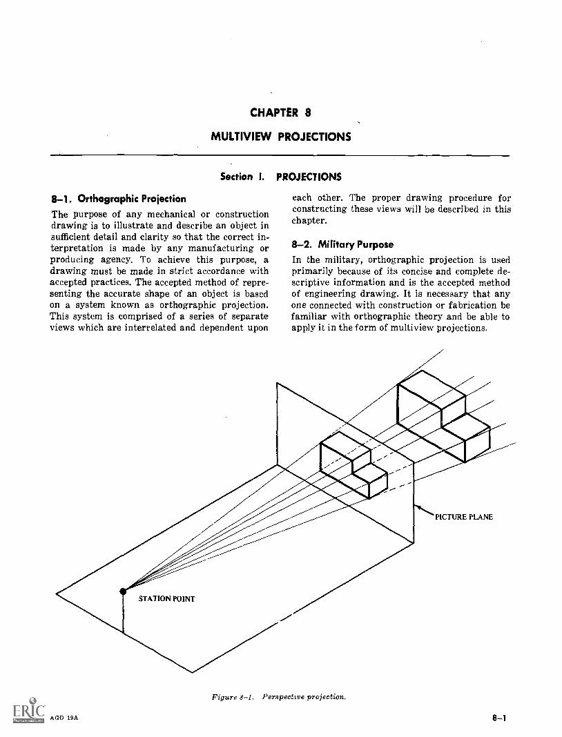
CHAPTER 8
MULTIVIEW PROJECTIONS
Section I. PROJECTIONS
8-1. Orthographic ProjectionThe purpose of any mechanical or constructiondrawing is to illustrate and describe an object insufficient detail and clarity so that the correct in-terpretation is made by any manufacturing orproducing agency. To achieve this purpose, adrawing must be made in strict accordance withaccepted practices. The accepted method of repre-senting the accurate shape of an object is basedon a system known as orthographic projection.This system is comprised of a series of separateviews which are interrelated and dependent upon
each other. The proper drawing procedure forconstructing these views will be described in thischapter.
8-2. Military PurposeIn the military, orthographic projection is usedprimarily because of its concise and complete de-scriptive information and is the accepted methodof engineering drawing. It is necessary that anyone connected with construction or fabrication befamiliar with orthographic theory and be able toapply it in the form of multiview projections.
STATION POINT
Figure 8-1. Perspective projection.
AGO 19A
PICTURE PLANE
8-1
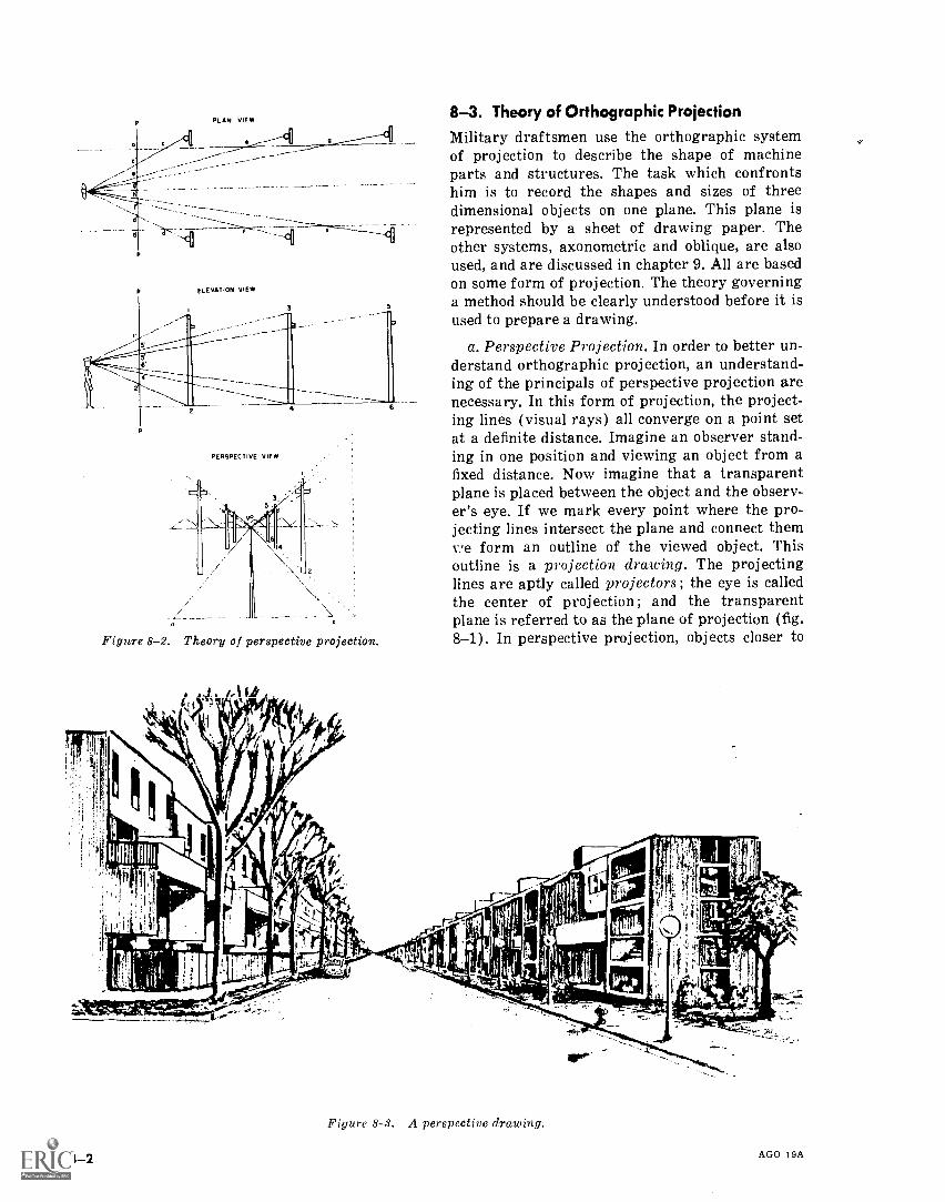
ELEVATION VIEW
PERSPECTIVE VIEW
4
n e
Figure 8-2. Theory of perspective projection.
8-3. Theory of Orthographic ProjectionMilitary draftsmen use the orthographic systemof projection to describe the shape of machineparts and structures. The task which confrontshim is to record the shapes and sizes of threedimensional objects on one plane. This plane isrepresented by a sheet of drawing paper. Theother systems, axonometric and oblique, are alsoused, and are discussed in chapter 9. All are basedon some form of projection. The theory governinga method should be clearly understood before it isused to prepare a drawing.
a. Perspective Projection. In order to better un-derstand orthographic projection, an understand-ing of the principals of perspective projection arenecessary. In this form of projection, the project-ing lines (visual rays) all converge on a point setat a definite distance. Imagine an observer stand-ing in one position and viewing an object from afixed distance. Now imagine that a transparentplane is placed between the object and the observ-er's eye. If we mark every point where the pro-jecting lines intersect the plane and connect themv,e form an outline of the viewed object. Thisoutline is a projection drawing. The projectinglines are aptly called projectors; the eye is calledthe center of projection ; and the transparentplane is referred to as the plane of projection (fig.8-1). In perspective projection, objects closer to
Figure 8-3. A perspective drawing.
8-2 AGO 19A
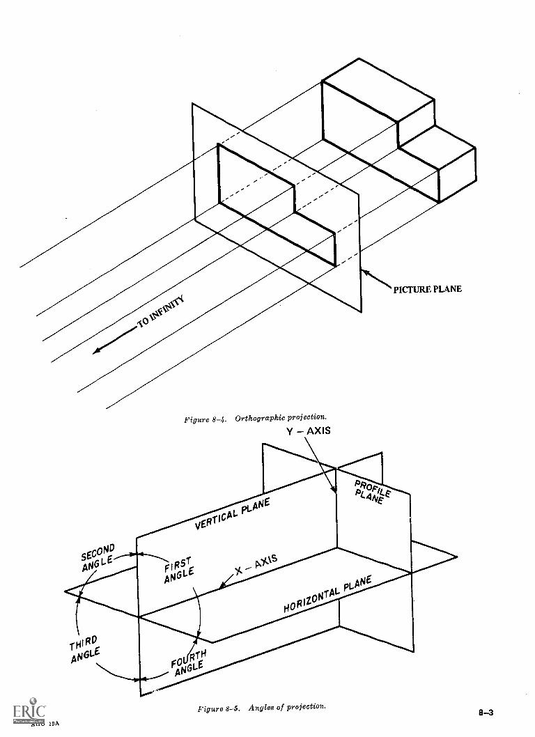
Figure 8-4. Orthographic projection.
Y - AXIS
Figure 8-5. Angles of projection.
AGO 19A
8-3
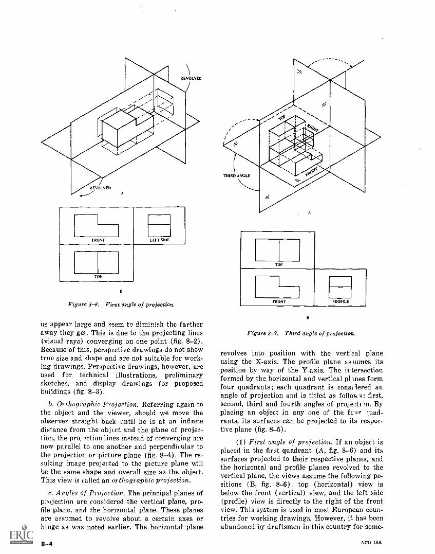
FRONT LEFT SIDE
TOP
B
Figure 8-6. First angle of projection.
us appear large and seem to diminish the fartheraway they get. This is due to the projecting lines(visual rays) converging on one point (fig. 8-2).Because of this, perspective drawings do not showtrue size and shape and are not suitable for work-ing drawings. Perspective drawings, however, areused for technical illustrations, preliminarysketches, and display drawings for proposedbuildings (fig. 8-3).
b. Orthographic Projection. Referring again tothe object and the viewer, should we move theobserver straight back until he is at an infinitedistance from the object and the plane of projec-tion, the pro:-Ttion lines instead of converging arenow parallel to one another and perpendicular tothe projection or picture plane (fig. 8-4). The re-sulting image projected to the picture plane willbe the same shape and overall size as the object.This view is called an orthographic projection.
c. Angles of Projection. The principal planes ofprojection are considered the vertical plane, pro-file plane, and the horizontal plane. These planesare assumed to revolve about a certain axes orhinge as was noted earlier. The horizontal plane
8-4
TOP
FRONT PROFILE
B
Figure 8-7. Third angle of projection.
revolves into position with the verUcal planeusing the X-axis. The profile plane assumes itsposition by way of the Y-axis. The ir tersectionformed by the horizontal and vertical pl Ines formfour quadrants; each quadrant is considered anangle of projection and is titled as follows : first,second, third and fourth angles of proje.;ti )n. Byplacing an object in any one of the fciir wad-rants, its surfaces can be projected to its respec-tive plane (fig. 8-5).
(1) First angle of projection. If an object isplaced in the first quadrant (A, fig. 8-6) and itssurfaces projected to their respective planes, andthe horizontal and profile planes revolved to thevertical plane, the views assume the following po-sitions (B, fig. 8-6) : top (horizontal) view isbelow the front (vertical) view, and the left side(profile) view is directly to the right of the frontview. This system is used in most European coun-tries for working drawings. However, it has beenabandoned by draftsmen in this country for some-
AGO 19A
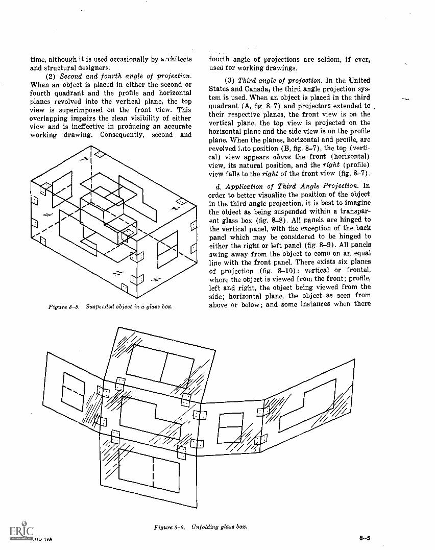
time, although it is used occasionally by Ecchitectsand structural designers.
(2) Second and fourth angle of projection.When an object is placed in either the second orfourth quadrant and the profile and horizontalplanes revolved into the vertical plane, the topview is superimposed on the front view. Thisoverlapping impairs the clean visibility of eitherview and is ineffective in producing an accurateworking drawing. Consequently, second and
Figure 8-8. Suspended object in a glass box.
fourth angle of projections are seldom, if ever,used for working drawings.
(3) Third angle of projection. In the UnitedStates and Canada,. the third angle projection sys-tem is used. When an object is placed in the thirdquadrant (A, fig. 8-7) and projectors extended totheir respective planes, the front view is on thevertical plane, the top view is projected on thehorizontal plane and the side view is on the profileplane. When the planes, horizontal and profile, arerevolved iiito position (B, fig. 8-7), the top (verti-cal) view appears above the front (horizontal)view, its natural position, and the right (profile)view falls to the right of the front view (fig. 8-7).
d. Application of Third Angle Projection. Inorder to better visualize the position of the objectin the third angle projection, it is best to imaginethe object as being suspended within a transpar-ent glass box (fig. 8-8). All panels are hinged tothe vertical panel, with the exception of the backpanel which may be considered to be hinged toeither the right or left panel (fig. 8-9). All panelsswing away from the object to come on an equalline with the front panel. There exists six planesof projection (fig. 8-10) : vertical or frontal,where the object is viewed from the front; profile,left and right, the object being viewed from theside; horizontal plane, the object as seen fromabove or below ; and some instances when there
Figure 8-9. Unfolding glass box.
AGO 19A 8-5
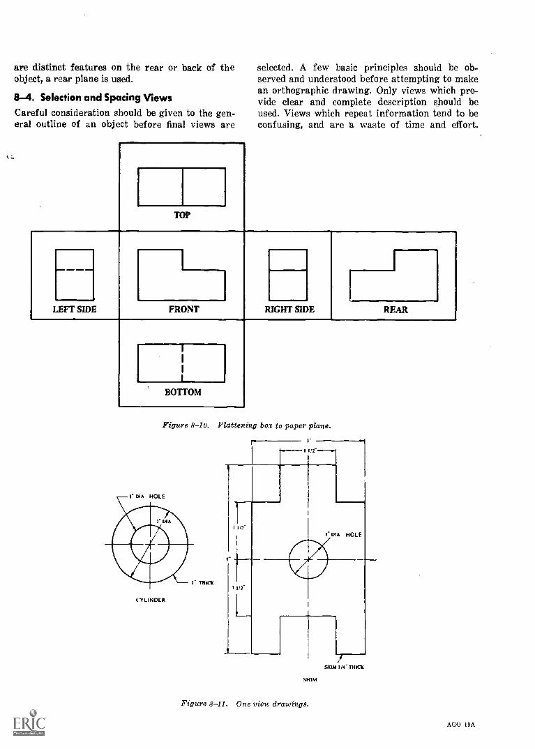
are distinct features on the rear or back of theobject, a rear plane is used.
8-4. Selection and Spacing ViewsCareful consideration should be given to the gen-eral outline of an object before final views are
TOP
selected. A few basic principles should be ob-served and understood before attempting to makean orthographic drawing. Only views which pro-vide clear and complete description should beused. Views which repeat information tend to beconfusing, and are 'a waste of time and effort.
HLEFT SIDE RIGHTFRONT SIDE REAR
BOTTOM
Figure 8-10. Flattening box to paper plane.
CYLINDER
8-6
I 1/2--.4
11/2-
SHIM
Figure 8-11. One view drawings.
SHIN IN-TRICK
AGO I9A
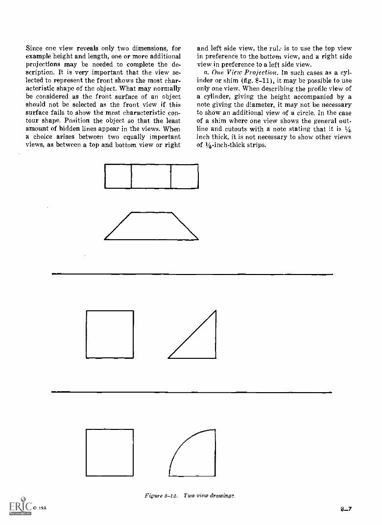
Since one view reveals only two dimensions, forexample height and length, one or more additionalprojections may be needed to complete the de-scription. It is very important that the view se-lected to represent the front shows the most char-acteristic shape of the object. What may normallybe considered as the front surface of an objectshould not be selected as the front view if thissurface fails to show the most characteristic con-tour shape. Position the object so that the leastamount of hidden lines appear in the views. Whena choice arises between two equally importantviews, as between a top and bottom view or right
AGO 19A
and left side view, the rule is to use the top viewin preference to the bottom view, and a right sideview in preference to a left side view.
a.. One View Projection. In such cases as a cyl-inder or shim (fig. 8-11), it may be possible to useonly one view. When describing the profile view ofa cylinder, giving the height accompanied by anote giving the diameter, it may not be necessaryto show an additional view of a circle. In the caseof a shim where one view shows the general out-line and cutouts with a note stating that it is I/4inch thick, it is not necessary to show other viewsof 14-inch-thick strips.
Figure 8-12. Two view drawings.
3-7
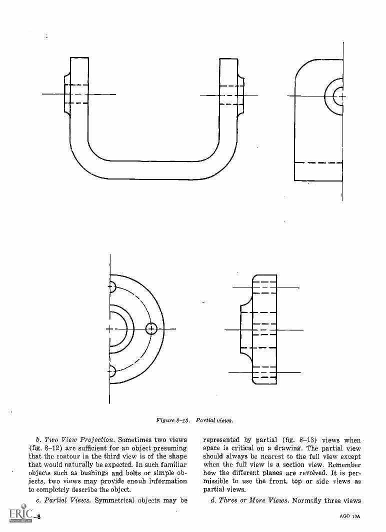
ION= NM MIMI
Figure 8-13. Partial views.
b. Two View Projection. Sometimes two views(fig. 8-12) are sufficient for an object presumingthat the contour in the third view is of the shapethat would naturally be expected. In such familiarobjects such as bushings and bolts or simple ob-jects, two views may provide enouh informationto completely describe the object.
c. Partial Views. Symmetrical objects may be
8-8
represented by partial (fig. 8-13) views whenspace is critical on a drawing. The partial viewshould always be nearest to the full view exceptwhen the full view is a section view. Rememberhow the different planes are revolved. It is per-missible to use the front, top or side views aspartial views.
d. Three or More Views. Normally three views
AGO 19A
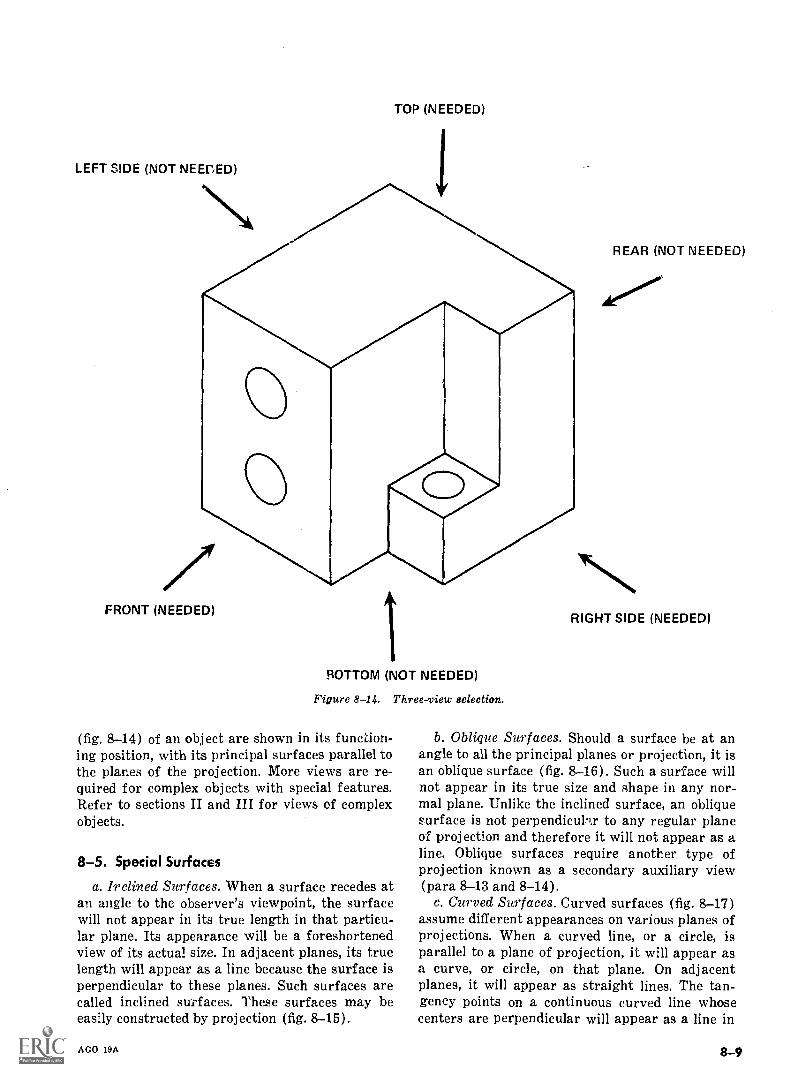
TOP (NEEDED)
LEFT SIDE (NOT NEEF,ED)
REAR (NOT NEEDED)
FRONT (NEEDED)
BOTTOM (NOT NEEDED)
Figure 8-14. Three-view selection.
(fig. 8-14) of an object are shown in its function-ing position, with its principal surfaces parallel tothe planes of the projection. More views are re-quired for complex objects with special features.Refer to sections II and III for views of complexobj ects.
8-5. Special Surfaces
a. Inclined Surfaces. When a surface recedes atan angle to the observer's viewpoint, the surfacewill not appear in its true length in that particu-lar plane. Its appearance will be a foreshortenedview of its actual size. In adjacent planes, its truelength will appear as a line because the surface isperpendicular to these planes. Such surfaces arecalled inclined surfaces. These surfaces may beeasily constructed by projection (fig. 8-15).
AGO 19A
RIGHT SIDE (NEEDED)
b. Oblique Surfaces. Should a surface be at anangle to all the principal planes or projection, it isan oblique surface (fig. 8-16). Such a surface willnot appear in its true size and shape in any nor-mal plane. Unlike the inclined surface, an obliquesurface is not perpendiculix to any regular planeof projection and therefore it will not appear as aline. Oblique surfaces require another type ofprojection known as a secondary auxiliary view(para 8-13 and 8-14).
c. Curved Surfaces. Curved surfaces (fig. 8-17)
assume different appearances on various planes ofprojections. When a curved line, or a circle, isparallel to a plane of projection, it will appear asa curve, or circle, on that plane. On adjacentplanes, it will appear as straight lines. The tan-gency points on a continuous curved line whosecenters are perpendicular will appear as a line in
8-9
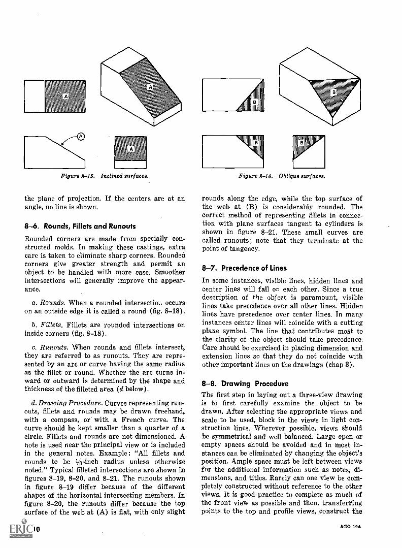
A
Figure 8-16. Inclined surfaces.
the plane of projection. If the centers are at anangle, no line is shown.
8-6. Rounds, Fillets and Runouts
Rounded corners are made from specially con-structed molds. In making these castings, extracare is taken to eliminate sharp corners. Roundedcorners give greater strength and permit anobject to be handled with more ease. Smootherintersections will generally improve the appear-ance.
a. Rounds. When a rounded intersectia occurson an outside edge it is called a round (fig. 8-18).
b. Fillets. Fillets are rounded intersections oninside corners (fig. 8-18).
c. Run outs. When rounds and fillets intersect,they are referred to as runouts. They are repre-sented by an arc or curve having the same radiusas the fillet or round. Whether the arc turns in-ward or outward is determined by the shape andthickness of the filleted area (d below).
d. Drawing Procedure. Curves representing run-outs, fillets and rounds may be drawn freehand,with a compass, or with a French curve. Thecurve should be kept smaller than a quarter of acircle. Fillets and rounds are not dimensioned. Anote is used near the principal view or is includedin the general notes. Example: "All fillets androunds to be 1/8-inch radius unless otherwisenoted." Typical filleted intersections are shown infigures 8-19, 8-20, and 8-21. The runouts shownin figure 8-19 differ because of the differentshapes of the horizontal intersecting members. Infigure 8-20, the runouts differ because the topsurface of the web at (A) is flat, with only slight
8-10
Figure 8-16. Oblique surfaces.
rounds along the edge, while the top surface ofthe web at (B) is considerably rounded. Thecorrect method of representing fillets in connec-tion with plane surfaces tangent to cylinders isshown in figure 8-21. These small curves arecalled runouts; note that they terminate at thepoint of tangency.
8-7. Precedence of Lines
In some instances, visible lines, hidden lines andcenter lines will fall on each other. Since a truedescription of the object is paramount, visiblelines take precedence over all other lines. Hiddenlines have precedence over center lines. In manyinstances center lines will coincide with a cuttingplane symbol. The line that contributes most tothe clarity of the object should take precedence.Care should be exercised in placing dimension andextension lines so that they do not coincide withother important lines on the drawings (chap 3).
8-8. Drawing ProcedureThe first step in laying out a three-view drawingis to first carefully examine the object to bedrawn. After selecting the appropriate views andscale to be used, block in the views in light con-struction lines. Wherever possible, views shouldbe symmetrical and well balanced. Large open orempty spaces should be avoided and in most in-stances can be eliminated by changing the object'sposition. Ample space must be left between viewsfor the additional information such as notes, di-mensions, and titles. Rarely can one view be com-pletely constructed without reference to the otherviews. It is good practice to complete as much ofthe front view as possible and then, transferringpoints to the top and profile views, construct the
Af.'3.0 19A
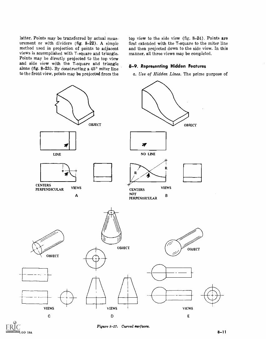
latter. Points may be transferred by actual meas-urement or with dividers (fig. 8-22). A simplemethod used in projection of points to adjacentviews is accomplished with T-square and triangle.Points may be directly projected to the top viewand side view with the T-square and trianglealone (fig. 8-23). By constructing a 45° miter lineto the front view, points may be projected from the
LINE
CENTERSPERPENDICULAR
VIEWS
VIEWS
A
OBJECT
top view to the side view (fig. 8-24). Points arefirst extended with the T-square to the miter lineand then projected down to the side view. In thismanner, all three views may be completed.
8-9. Representing Hidden Features
a. Use of Hidden Lines. The prime purpose of
14111OBJECT
NO LINE
CENTERSNOTPERPENDICULAR
OBJECT
VIEWS
C D
R
VIEWS
B
1'igure 8-17. Curved surfacea.AGO 19A
VIEWS
E
8-11
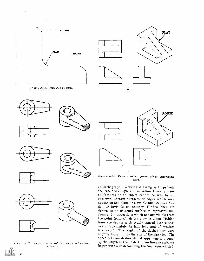
ROUND
flU.ITROUND
Figure 8-18. Rounds and fillets.
Figure 8-19. Runouts with ditterem' shape intersectingmembers.
8-12
A
B
Figure 8-20. Runouts with different shape intersectingwebs.
an orthographic working drawing is to provideaccurate and complete information. In many casesall features of an object cannot oe seen by anobserver. Certain surfaces or edges which mayappear on one plane as a visible line becomes hid-den or invisible on another. Hidden lines aredrawn on an external surface to represent sur-faces and intersections which are not visible fromthe point from which the view is taken. Hiddenlines are drawn with evenly spaced dashes thatare approximately 1/8 inch long and of mediumline weight. The length of the dashes may varyslightly according to the size of the drawing. Thespace between dashes should approximately equal14, the length of the dash. Hidden lines are alwaysbegun with a dash touching the line from which it
AGO 19A
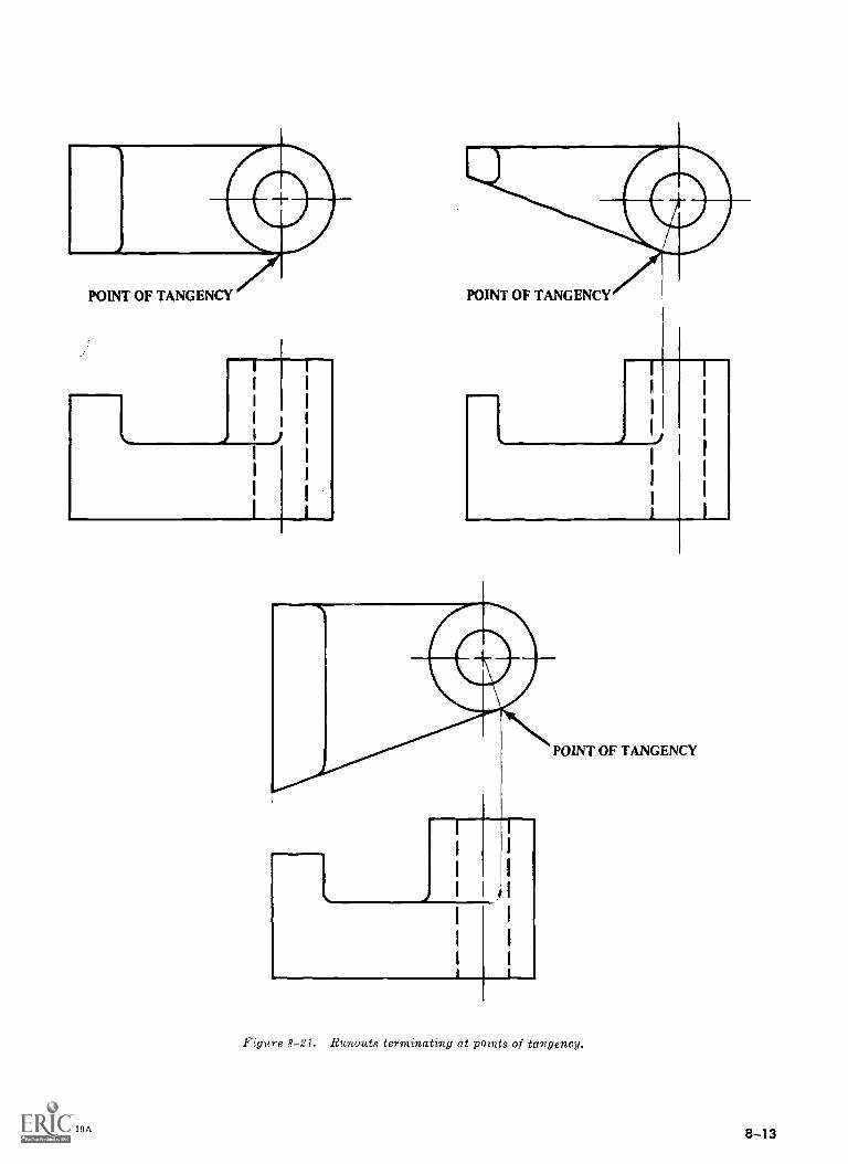
POINT OF TANGENCY
I
I I
I I
I I
I ) I
I
I
I
I
I
AGO 19A
0POINT OF TANGENCY
I
POINT OF TANGENCY
Figure 8-21. Runouts terminating at points of tangency.
8-13
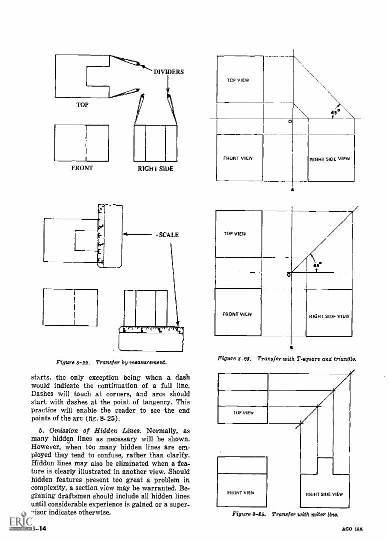
FRONT RIGHT SIDE
SCALE
Figure 8-22. Transfer by measurement.
starts, the only exception being when a dashwould indicate the continuation of a full line.Dashes will touch at corners, and arcs shouldstart with dashes at the point of tangency. Thispractice will enable the reader to see the endpoints of the arc (fig. 8-25).
b. Omission of Hidden Lines. Normally, asmany hidden lines as necessary will be shown.However, when too many hidden lines are em-ployed they tend to confuse, rather than clarify.Hidden lines may also be eliminated when a fea-ture is clearly illustrated in another view. Shouldhidden features present too great a problem incomplexity, a section view may be warranted. Be-ginning draftsmen should include all hidden linesuntil considerable experience is gained or a super-visor indicates otherwise.
8-14
TOP VIEW
FRONT VIEW
A
15 \
RIGHT SIDE VIEW
TOP VIEW
430pjO
FRONT VIEW RIGHT SIDE VIEW
Figure 8 -28. Transfer with T-square and triangle.
IOP VIEW
FRONT VIEW RIGHT SIRE VIEW
Figure 8-24. Transfer with miter line.
AGO 19A
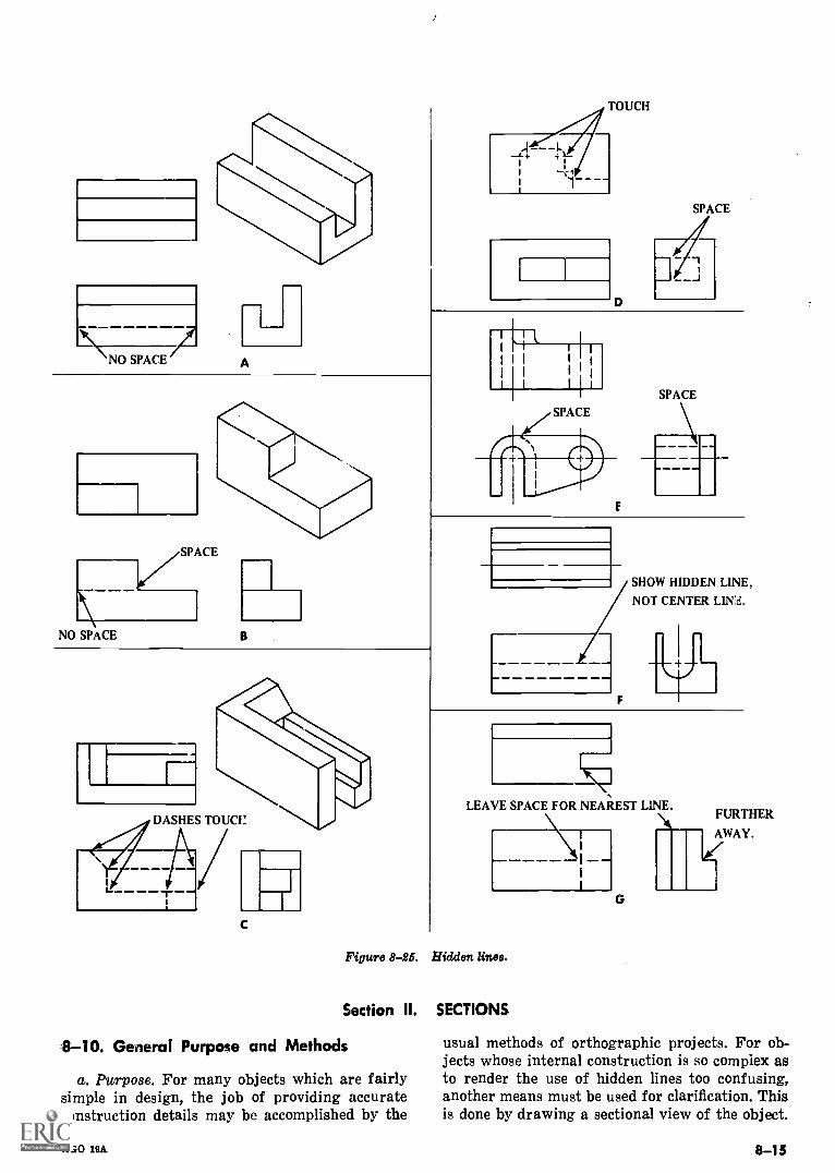
A
D
SPACE
NO SPACE B
I
7- 1t
I I
1
III I
I
I I 1
SPACE
DASHES TOUCI!
C
Figure 8-25.
Section II.
8-10. General Purpose and Methods
a. Purpose. For many objects which are fairlysimple in design, the job of providing accurateconstruction details may be accomplished by the
AGO 19A
SHOW HIDDEN LINE,
NOT CENTER LINZ,.
iv
LEAVE SPACE FOR NEAREST LINE.
-----I --1--- It
G
Hidden lines.
SECTIONS.
usual methods of orthographic projects. For ob-jects whose internal construction is so complex asto render the use of hidden lines too confusing,another means must be used for clarification. Thisis done by drawing a sectional view of the object.
8-15
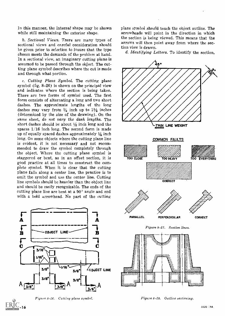
In this manner, the internal shape may be shownwhile still maintaining the exterior shape.
b. Sectional Views. There are many types ofsectional views and careful consideration shouldbe given prior to selection to insure that the typechosen meets the demands of the problem at hand.In a sectional view, an imaginary cutting plane isassumed to be passed through the object. The cut-ting plane symbol describes where the cut is madeand through what portion.
c. Cutting Plane Symbol. The cutting planesymbol (fig. 8-26) is shown on the principal viewand indicates where the section is being taken.There are two forms of symbol used. The firstform consists of alternating a long and two shortdashes. The approximate lengths of the longdashes may vary from 34 inch up to 11/2 inches(determined by the size of the drawing). On thesame sheet, do not vary the dash lengths. Theshort dashes should be about 1/8 inch long and thespaces 1/16 inch long. The second form is madeup of equally spaced dashes approximately 1/4 inchlong. On some objects where the cutting plane lineis evident, it is not necessary and not recom-mended to draw the symbol completely throughthe object. Where the cutting plane symbol isstaggered or bent, as in an offset section, it isgood practice at all times to construct the com-plete symbol. When it is clear that the cuttingplane falls along a center line, the practice is toomit the symbol and use the center line. Cuttingline symbols should be heavier than the object lineand should be easily recognizable. The ends of thecutting plane line are bent at a 90° angle and endwith a bold arrowhead. No part of the cutting
Figure 8-26. Cutting plane sgmbol.
8-16
plane symbol should touch the object outline. Thearrowheads will point in the direction in whichthe section is being viewed. This means that thearrows will then point away from where the sec-tion view is drawn.
d. Identifying Letters. To identify the section,
TOO CLOSE
THIN LINE WEIGHT
COMMON FAULTS
TOO HEAVY 00 EVERYTHING
CORRECT
PERPENDICULAR
Figure 8-27. Section lines.
CORRECT
Figure 8-28. Outline sectioning.
AGO 19A
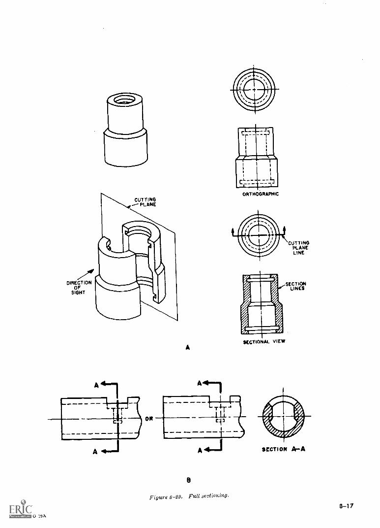
.-911rDIRECTION
OFSIGHT
CUTTING--- PLANE
'GO 19A
OR
A
ORTHOGRAPHIC
SECTIONAL VIEW
CUTTINGPLANELINE
SECTIONLINES
Figure 8-29. Full sectioning.
SECTION A-A
8-17
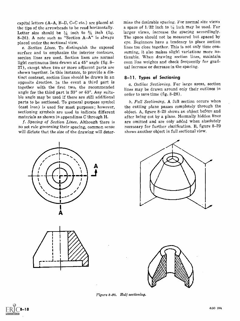
capital letters (AA, BD, CC etc.) are placed atthe tips of the arrowheads to be read horizontally.Letter size should be 1% inch to 3/8 inch (fig.8-26). A note such as "Section AA" is alwaysplaced under the sectional view.
e. Section Lines. To distinguish the exposedsurface and to emphasize the interior contours,section lines are used. Section lines are normallight continuous lines drawn at a 45° angle (fig. 8-27), except when two or more adjacent parts areshown together. In this instance, to provide a dis-tinct contrast, section lines should be drawn in anopposite drection. In the event a third part istogether with the first two, the recommendedangle for the third part is 30° or 60°. Any suita-ble angle may be used if there are still additionalparts to be sectioned. To general purpose symbol(cast iron) is used for most purposes ; however,sectioning symbols are used to indicate differentmaterials as shown in appendixes C through H.
f. Spacing of Section Lines. Although there isno set rule governing their spacing, common sensewill dictate that the size of the drawing will deter-
8-18
mine the desirable spacing. For normal size viewsa space of 1/32 inch to 1/8 inch may be used. Forlarger views, increase the spacing accordingly.The space should not be measured but spaced byeye. Beginners have a tendency to place sectionlines too close together. This is not only time con-suming, it also makes slight variations more no-ticeable. When drawing section lines, maintaineven line weights and check frequently for grad-ual increase or decrease in the spacing.
8-11. Types of Sectioninga. Outline Sectioning. For large areas, section
lines may be drawn around only their outlines inorder to save time (fig. 8-28).
b. Full Sectioning. A. full section occurs whenthe cutting plane passes completely through theobject. A, figure 8-29 shows an object before andafter being cut by a plane. Normally hidden linesare omitted and are only added when absolutelynecessary for further clarification. B, figure 8-29
shows another object in full sectional view.
Figure 8-80. Half sectioning.
AGO 19A
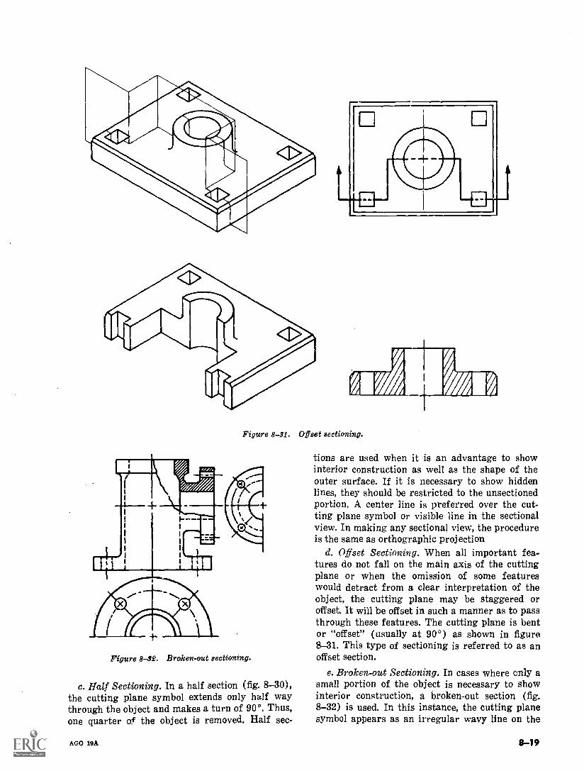
Figure 8-31. Offset sectioning.
Figure 8 -32. Broken-out sectioning.
c. Half Sectioning. In a half section (fig. 8-30),the cutting plane symbol extends only half waythrough the object and makes a turn of 90°. Thus,one quarter of the object is removed. Half sec-
AGO 19A
tions are used when it is an advantage to showinterior construction as well as the shape of theouter surface. If it is necessary to show hiddenlines, they should be restricted to the unsectionedportion. A center line is preferred over the cut-ting plane symbol or visible line in the sectionalview. In making any sectional view, the procedureis the same as orthographic projection
d. Offset Sectioning. When all important fea-tures do not fall on the main axis of the cuttingplane or when the omission of some featureswould detract from a clear interpretation of theobject, the cutting plane may be staggered oroffset. It will be offset in such a manner as to passthrough these features. The cutting plane is bentor "offset" (usually at 900) as shown in figure8-31. This type of sectioning is referred to as anoffset section.
e. Broken-out Sectioning. In cases where only asmall portion of the object is necessary to showinterior construction, a broken-out section (fig.8-32) is used. In this instance, the cutting planesymbol appears as an irregular wavy line on the
8-19
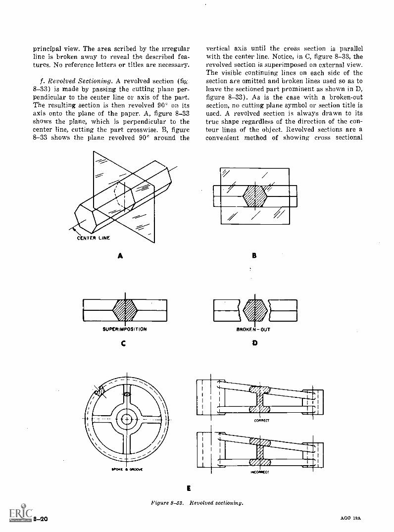
principal view. The area scribed by the irregularline is broken away to reveal the described fea-tures. No reference letters or titles are necessary.
f. Revolved Sectioning. A revolved section (fig.8-33) is made by passing the cutting plane per-pendicular to the center line or axis of the part.The resulting section is then revolved 90° on itsaxis onto the plane of the paper. A, figure 8-33shows the plane, which is perpendicular to thecenter line, cutting the part crosswise. B, figure8-33 shows the plane revolved 90° around the
CENTER LINE
A
SUPERIMPOSITION
C
srostc amoovc
8 20
E
vertical axis until the cross section is parallelwith the center line. Notice, in C, figure 8-33, therevolved section is superimposed on external view.The visible continuing lines on each side of thesection are omitted and broken lines used so as toleave the sectioned part prominent as shown in D,figure 8-33). As is the case with a broken-outsection, no cutting plane symbol or section title isused. A revolved section is always drawn to itstrue shape regardless of the direction of the con-tour lines of the object. Revolved sections are aconvenient method of showing cross sectional
/B
BROKEN OUT
Figure 8-33. Revolved sectioning.
AGO 19A
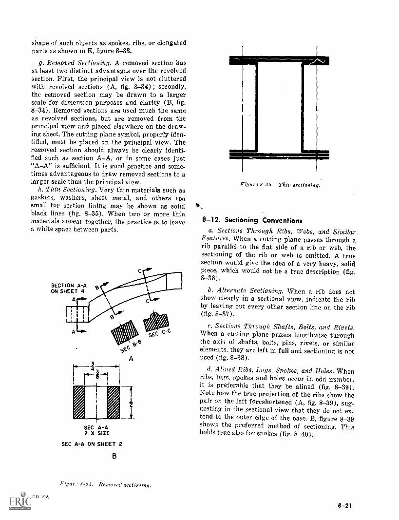
shape of such objects as spokes, ribs, or elongatedparts as shown in E, figure 8-33.
g. Removed Sectioning. A removed section hasat least two distinct advantages over the revolvedsection. First, the principal view is not clutteredwith revolved sections (A, fig. 8-34) ; secondly,the removed section may be drawn to a largerscale for dimension purposes and clarity (B, fig.8-34). Removed sections are used much the sameas revolved sections, but are removed from theprincipal view and placed elsewhere on the draw-ing sheet. The cutting plane symbol, properly iden-tified, must be placed on the principal view. Theremoved section should always be clearly identi-fied such as section AA, or in some cases just"AA" is sufficient. It is good practice and some-times advantageous to draw removed sections to alarger scale than the principal view.
h. Thin Sectioning. Very thin materials such asgaskets, washers, sheet metal, and others toosmall for section lining may be shown as solidblack lines (fig. 8-35). When two or more thinmaterials appear together, the practice is to leavea white space between parts.
SECTION A-AON SHEET 4
SEC A-A2 X SIZE
SEC A-A ON SHEET 2
B
Figur: 8-34. Removed sectioning.
ACO 19A
Figure 8-35. Thin sectioning,
3/1L_
8-12. Sectioning Conventions
a. Sections Through Ribs, Webs, and Similar.Features. When a cutting plane passes through arib parallel to the flat side of a rib or web, thesectioning of the rib or web is omitted. A truesection would give the idea of a very heavy, solidpiece, which would not be a true description (fig.8-36).
b. Alternate Sectioning. When a rib does notshow clearly in a sectional view, indicate the ribby leaving out every other section line on the rib(fig. 8-37).
c. Sections Through Shafts, Bolts, and Rivets.When a cutting plane passes lengthwise throughthe axis of shafts, bolts, pins, rivets, or similarelements, they are left in full and sectioning is notused (fig. 8-38).
if. Alined Ribs, Lugs, Spokes, and Holes. Whenribs, lugs, spokes and holes occur in odd number,it is preferable that they be alined (fig. 8-39).Note how the true projection of the ribs show thepair on the ]eft foreshortened (A, fig. 8-39), sug-gesting in the sectional view that they do not ex-tend to the outer edge of the base. B, figure 8-39shows the preferred method of sectioning. Thisholds true also for spokes (fig. 8-40).
8-2!
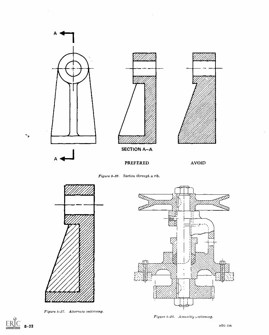
SECTION A-A
PREFERED
Figure 8-36. Section through a rib.
Figure 8-37. Alternate sectzonzng.
8-22
AVOID
Figure 8-38. Assembly s3ctioning.
AGO 19A
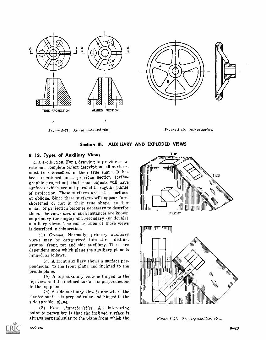
TRUE PROJECTION
A
ALINED SECTION
Figure 8-39. Alined holes and ribs. Figure 8-40. Alined spokes.
Section III. AUXILIARY AND EXPLODED VIEWS
8-13. Types of Auxiliary Viewsa. Introduction. For a drawing to provide accu-
rate and complete object description, all surfacesmust be represented in their true shape. It hasbeen mentioned in a previous section (ortho-graphic projection) that some objects will havesurfaces which are not parallel to regular planesof projection. These surfaces are called inclinedor oblique. Since these surfaces will appear fore-shortened or not in their true shape, anothermeans of projection becomes necessary to describethem. The views used in such instances are knownas primary (or single) and secondary (or double)auxiliary views. The construction of these viewsis described in this section.
;1) Groups. Normally, primary auxiliaryviews may be categorized into three distinctgroups: front, top and side auxiliary. These aredependent upon which plane the auxiliary plane ishinged, as follows:
(o) A front auxiliary shows a surface per-pendicular to the front plane and inclined to theprofile plane.
(b) A top auxiliary view is hinged to thetop view and the inclined surface is perpendicularto the top plane.
(c) A side auxiliary view is one where theslanted surface is perpendicular and hinged to theside (profile' plane.
(2) View characteristics. An interestingpoint to remember is that the inclined surface isalways perpendicular to the plane from which the
AGO 19A
TOP
FRONT
Figure 8-41. Primary auxiliary view.
8-23
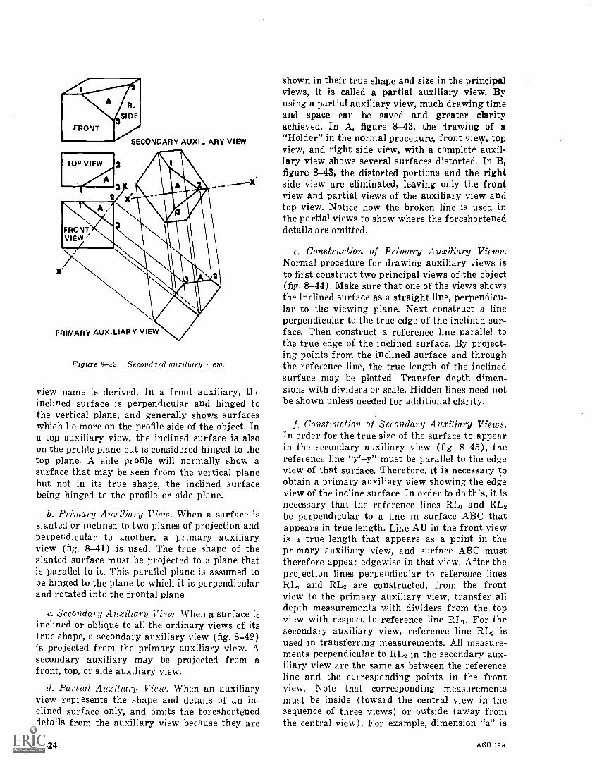
SECONDARY AUXILIARY VIEW
TOP VIEW
.K412
2
3
FRONTVIEW
PRIMARY AUXILIARY VIEW
Figure 8-42. Secondard auxiliary view.
x'
view name is derived. In a front auxiliary, theinclined surface is perpendicular and hinged tothe vertical plane, and generally shows surfaceswhich lie more on the profile side of the object. Ina top auxiliary view, the inclined surface is alsoon the profile plane but is considered hinged to thetop plane. A side profile will normally show asurface that may be seen from the vertical planebut not in its true shape, the inclined surfacebeing hinged to the profile or side plane.
b. Primary Auxiliary View. When a surface isslanted or inclined to two planes of projection andperpendicular to another, a primary auxiliaryview (fig. 8-41) is used. The true shape of theslanted surface must be projected to a plane thatis parallel to it. This parallel plane is assumed tobe hinged to the plane to which it is perpendicularand rotated into the frontal plane.
c. Secondary Auxiliary View. When a surface isinclined or oblique to all the ordinary views of itstrue shape, a secondary auxiliary view (fig. 8-42)
is projected from the primary auxiliary view. Asecondary auxiliary may be projected from afront, top, or side auxiliary view.
d. Partial Auxiliary View. When an auxiliaryview represents the shape and details of an in-clined surface only, and omits the foreshorteneddetails from the auxiliary view because they are
8-24
shown in their true shape and size in the principalviews, it is called a partial auxiliary view. Byusing a partial auxiliary view, much drawing timeand space can be saved and greater clarityachieved. In A, figure 8-43, the drawing of a"Holder" in the normal procedure, front view, topview, and right side view, with a complete auxil-iary view shows several surfaces distorted. In B,figure 8-43, the distorted portions and the rightside view are eliminated, leaving only the frontview and partial views of the auxiliary view andtop view. Notice how the broken line is used inthe partial views to show where the foreshorteneddetails are omitted.
e. Construction of Primary Auxiliary Views.Normal procedure for drawing auxiliary views isto first construct two principal views of the object(fig. 8-44). Make sure that one of the views showsthe inclined surface as a straight line, perpendicu-lar to the viewing plane. Next construct a lineperpendicular to the true edge of the inclined sur-face. Then construct a reference line parallel tothe true edge of the inclined surface. By project-ing points from the inclined surface and throughthe reference line, the true length of the inclinedsurface may be plotted. Transfer depth dimen-sions with dividers or scale. Hidden lines need notbe shown unless needed for additional clarity.
f. Construction of Secondary Auxiliary Views.In order for the true size of the surface to appearin the secondary auxiliary view (fig. 8-45), tnereference line "y'y" must be parallel to the edgeview of that surface. Therefore, it is necessary toobtain a primary auxiliary view showing the edgeview of the incline surface. In order to do this, it isnecessary that the reference lines RL1 and RL2be perpendicular to a line in surface ABC thatappears in true length. Line AB in the front viewis A true length that appears as a point in theprimary auxiliary view, and surface ABC musttherefore appear edgewise in that view. After theprojection lines perpendicular to reference linesRL1 and RL2 are constructed, from the frontview to the primary auxiliary view, transfer alldepth measurements with dividers from the topview with respect to reference line RL -1. For thesecondary auxiliary view, reference line RL2 isused in transferring measurements. All measure-ments perpendicular to RL2 in the secondary aux-iliary view are the same as between the referenceline and the corresponding points in the frontview. Note that corresponding measurementsmust be inside (toward the central view in thesequence of three views) or outside (away fromthe central view). For example, dimension "a" is
AGO 19A
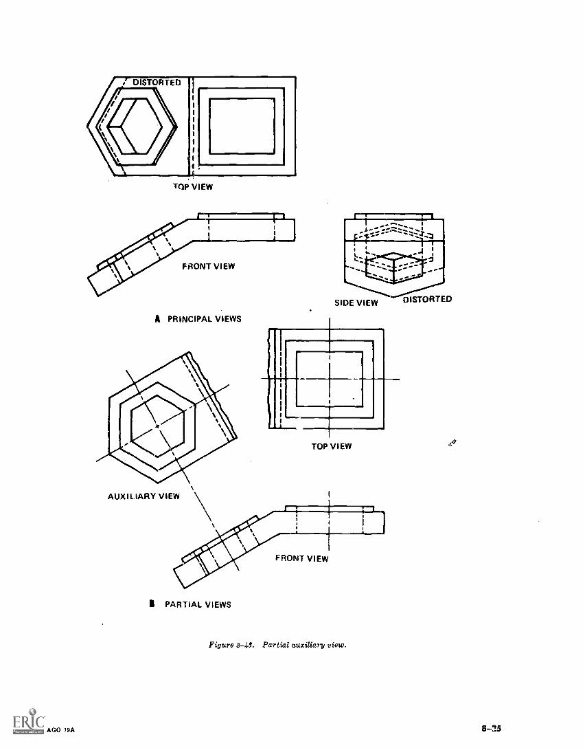
TQP VIEW
A PRINCIPAL VIEWS
TOP VIEW
AUXILIARY VIEW
I PARTIAL VIEWS
FRONT VIEW
Figure 8-48. Partial auxiliary view.
AGO 19A 13-2.5
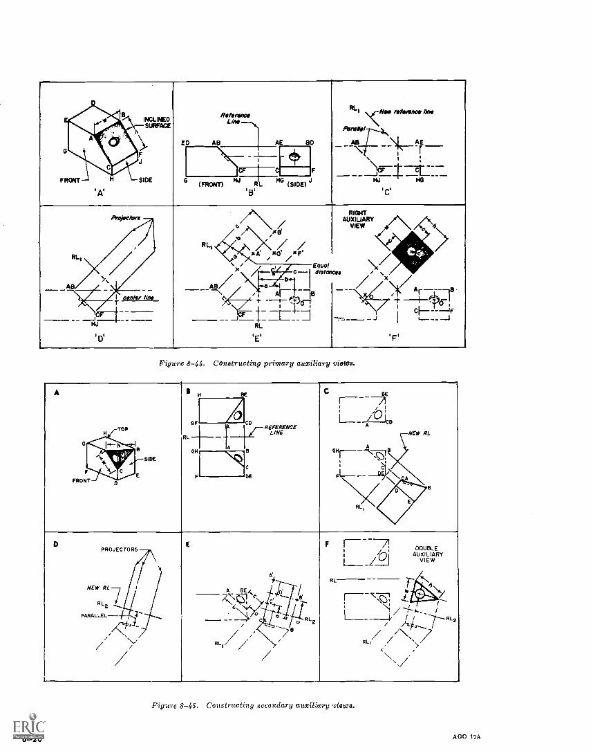
FRONT
INCLINEDB
SURFACE
SIDE
'A'
ED
Reference
AB
Lew
AE BD
F
RLI `,-Net reference line
Arraile/-7--.41/4
AB / \[ AE
ctlfr,---f 11\
r.,
CF C
.)(SIDE)
jCF_ .1=--140HJ HG
(FRONT) RLIQ
'C'
Projectors
AB
.o
RLl 41*o
. /0 .
RIGHTAUXIUARY
VIEW ",/
Ar --4,---18
'X/ /
AB/c
---113
Equaldistances
.
b
ArgF)c nrcitsLw 4,
__f__E!_, --t_1 '._ *I'cr.cl-- ----IF
_,_ .______J
'F'
JoHJ
'DI
RL
'E'
Figure 8-44. Constructing primary auxiliary views.
A
F
FRONT
TOPH
.11ballg-'t 4)::r
a
SIDE
1H
OF
BE
ji)/- RE:ENREENCE
C BEr-- -7I1 oi1 _ 1-1CD
NEW RI.
D
E
%A
AGH ..,
RL
B
C
DE
OH
F 1[-
7,1
CIC:I/Fl---
RL,
D
PARALLEL-1-
PROJECTORS
NEW RL
R L2
E
A BE
a
..1B//
DOUBLEAUXILIARY
VIEW
F r--- 7!1
I
/,--11
Z LIJ
RL 701.
7(7.--. RL 2
/4./..r--......
/Ns,s)/
,.,/
L___,
...,
/,,
R LI /
//RL , .
i\\
Figure 8-45. Constructing secondary auxiliary views.
8-26 AGO 19A
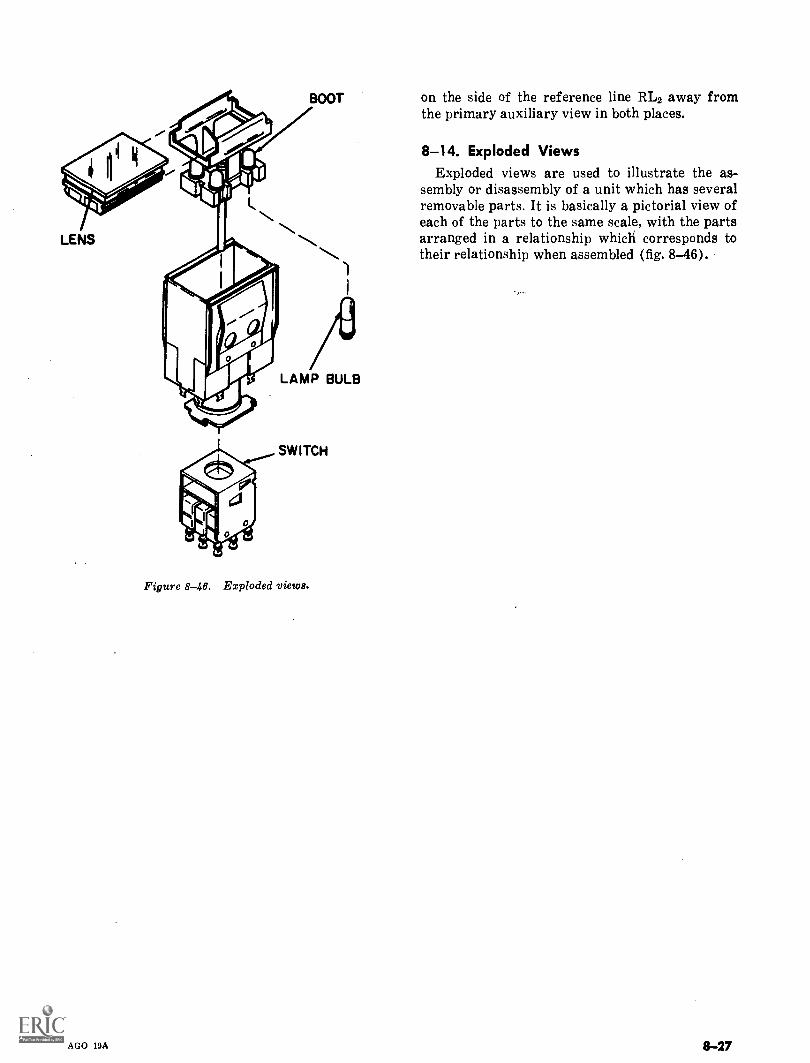
BOOT on the side of the reference line RL2 away fromthe primary auxiliary view in both places.
LENS
AGO 19A
LAMP BULB
SWITCH
Figure 8-46. Exploded view&
8-14. Exploded ViewsExploded views are used to illustrate the as-
sembly or disassembly of a unit which has severalremovable parts. It is basically a pictorial view ofeach of the parts to the same scale, with the partsarranged in a relationship which corresponds totheir relationship when assembled (fig. 8-46).
8-27
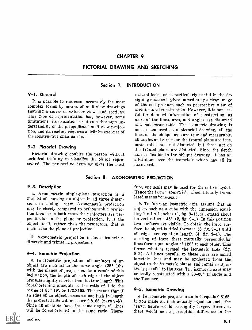
CHAPTER 9
PICTORIAL DRAWING AND SKETCHING
Section I.
9-1. Generalit is possible to represent accurately the most
complex forms by means of multiview drawingsshowing a series of exterior views and sections.This type of representation has, however, somelimitations : its execution requires a thorough un-derstanding of the priviples.of multiview projec-tion, and its reading requires a definite exercise ofthe constructive imagination.
9-2. Pictorial DrawingPictorial drawing enables the person without
technical training to visualize the object repre-sented. The perspective drawing gives the most
Section
INTRODUCTION
natural look and is particularly useful in the de-signing state as it gives immediately a clear imageof the end product, such as perspective view ofarchitectural construction. However, it is not use-ful for detailed information of construction, asmost of the lines, arcs, and angles are distortedand not measurable. The isometric drawing ismost often used as a pictorial drawing, all thelines on the oblique axis are true and measurable,all angles and circles on the frontal plane are true,measurable, and not distorted, but those not onthe frontal plane are distorted. Since the depthaxis is flexible in the oblique drawing, it has anadvantage over the isometric which has all itsaxes fixed.
II. AXONOMETRIC PROJECTION
9-3. Descriptiona. Axoriometric single-plane projection is a
method of showing an object in all three dimen-sions in o. single view. Axonometric projectionmay be closely compared to orthographic projec-tion because in both cases the projectors are per-pendicular to the plane or projection. It is theobject itself, rather than the projectors, that isinclined to the plane of projection.
b. Axonometric projection includes isometric,dimetric and trimetric projections.
9-4. Isometric Projectiona. In isometric projection, all surfaces of an
object are inclined to the same angle (35° 16')with the planes of projection. As a result of thisinclination, the length of each edge of the objectprojects slightly shorter than its true length. Thisforeshortening amounts to the ratio of 1 to thecosine of 35° 16', or 1/0.8165. This means that ifan edge of an object measures one inch in lengththe projected line will measure 0.8165 (para 9-5).Since all surfaces form the same angle, all lineswill be foreshortened to the same ratio. There-
AGO 19A
fore, one scale may be used for the entire layout.Hence the term "isometric", which literally trans-lated means "one-scale".
b. To form an isometric axis, assume that anobject, such as a cube with the dimension equal-ling 1 x 1 x 1 inches (1, fig. 9-1), is rotated aboutits vertical axis 45° (2, fig. 9-1). In this positiontwo surfaces are visible. To obtain the third sur-face the object is titled forward (3, fig. 9-1) untilall edges are equal in length (4, fig. 9-1). Themeeting of these three mutually perpendicularlines form equal angles of 120° to each other. Thisforms what is termed the isometric axes (fig.9-2). All lines parallel to these lines are callediometric lines and may be projected from theobject to the isometric planes and remain respec-tively parallel to the axes. The isometric axes maybe easily constructed with a 30-60° triangle andthe T-square.
9-5. Isometric Drawinga. In isometric projection an inch equals 0.8165.
If you made an inch actually equal an inch, thedrawn figure would be slightly larger. However,there would be no perceptible difference in the
9-1
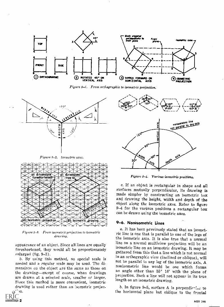
TOP
4
FRONT
2
SIOE
5 5OI ORTHOGRAPMC
3 4
45 Body dfrowpapr IDfront plane
Frontplane Isometric one
7 e 50 ROTATED 45' ON
VERTICAL AXIS0 TIPPED FORWARD ON
HORIZONTAL AXIS
Figure 9-1. From orthographic to isometric projection.
Figure 9-2.. Isometric axes.
mos -4,04,-41001." stabs'esrate.ma6"k4mmastepseall dimensions 4 a I imenslonspraliaria_
41111:foreshO.terTea,-Trd true zipmplotempa411:418EkWIIPA4111" WiffNARRESIEniVafto..!TTIESMISCARM102E11irONIMUCUNNUNIOR1150Miltij160.-EPardIS_BI*11611 "dbaleNNMEMINNINARMIRNI.bala' .911ENNIMMIR1NAMIMENPVINMIKINGENO %OSAllauSENEW041111411210410ffilitZMAI
16:11MAIPIAMP4Ibign111:1MBI.4nunrimarans _-.aobmnEaEr.-:ob-ivmx.so.up.apsaoiwa';w gam.(A Isometric-projection (B Isometric !awing IN
.411 -41141Ziellhib. IanFigure 9-3. From isometric projection to isometric
drawing.
appearance of an object. Since all lines are equallyforeshortened, they would all be proportionatelyenlarged (fig. 9-3).
b. By using this method, no special scale isneeded and a regular scale may be used. The di-mensions on the object are the same as those onthe drawingexcept of course, when drawingsare drawn at a selected scale, smaller or larger.Since this method is more convenient, isometricdrawing is used rather than an isometric projec-tion.
9-2
riaa6;
,e 12o1,1 xel eroor.
® ISOMETRICPROJECTION
1.
2.) /4- -1204Tte.e )20MO° I
Figure 9-4. Various isometric positions.
c. If an object is rectangular in shape and allsurfaces mutually perpendicular, its drawing ismade simpler by constructing an isometric boxand drawing the height, width and depth of theobject along the isometric axes. Refer to figure9-4 for the various positions a rectangular boxcan be drawn using the isometric axes.
9-6. Nonisometric Linesa. It has been previously stated that an isomet-
ric line is one that is parallel to one of the legs ofthe isometric axis. It is also true that a normalline on a normal multiview projection will be anisometric line on an isometric drawing. It may begathered from this that a line which is not normalin an orthographic view (inclined or oblique), willnot be parallel to any leg of the isometric axis. Anonisometric line would be one which formsan angle other than 35° 16' with the plane ofprojection. Such aline will not appear in its truelength on an isometric drawing.
b. In figure 9-5, surface A is perpendie-10.r tothe horizontal plane but oblique to the frontal
AGO 19A
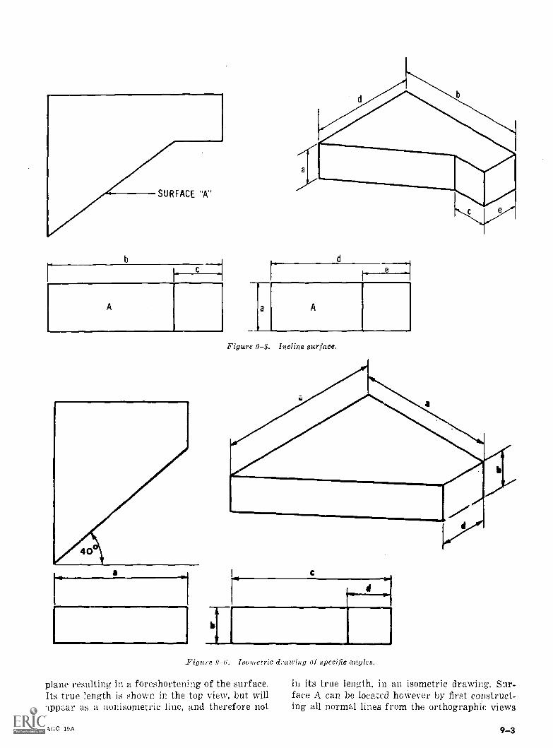
b
A
a
d
fi
e
a A
Figure 9-5. Incline surface.
Figure 9-6. Isometric drawing of specific angles.
plane resulting in a foreshortening of the surface.Its true length is shown in the top view, but willapp,u as a uonisornetric line, and therefore not
AGO 19A
in its true length, in an isometric drawing. Sur-face A can be located however by first construct-ing all normal lines from the orthographic views
9-3
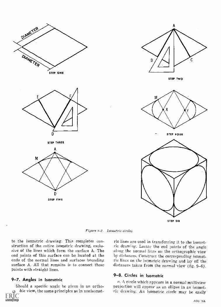
STEP ONE
D
STEP THREE
A
D
STEP FIVE
Figure 9-7. Isometric circles.
to the isometric drawing. This completes con-struction of the entire isometric drawing, exclu-sive of the lines which form the surface A. Theend points of this surface can be located at theends of the normal lines and surfaces boundingsurface A. All that remains is to connect thesepoints with straight lines.
9-7. Angles in IsometricShould a specific angle be given in an ortho-
graphic view, the same principles as in nonisomet-
9-4
STEP TWO
STEP FOUR
STEP SIX
ric lines are used in transferring it to the isomet-ric drawing. Locate the end points of the anglealong the normal lines on the orthographic viewby distances. Construct the corresponding isomet-ric lines on the isometric drawing and lay off thedistances taken from the normal view (fig. 9-6).
9-8. Circles in Isometrica. A circle which appears in a normal multiview
projection will appear as an ellipse in an isomet-ric drawing. An isometric circle may be easily
AGO 19A

constructed by the four center method. Thismethod is usually accurate enough for most daw-ings. First, construct an isometric square thatequals the diameter of the circle, step one, figure
Figure 9-8. Isometric circle is the rear.
1181 ANC I. "1"/ I MICK NI-Stil
'411111.P'
4
Figure 9-9. Isometric arcs,
AGO 19A
CURVE INORTHOGRAPHIC
CURVE INISOMETRIC
9-7. Next with the 60 side of the triangle, drawlines AB and AC from corner A, step two. Drawlines DE and DF from corner D, step three. Drawtwo arcs with radius xM, with .enters x and y,step four. Draw tw o arcs with radius DM withcenters D and A, step five. Step six shows theiometric circles for the front, top, and right sideviews.
b. To show portions of a circle on the rear of anobject (fig. 9-8), lay off the thickness of theobject or the depth of the hole. Then by projectingthe centers of the radii us d on the front of theobject, back a distance eq,,a1 to the thickness ofthe object, draw as much of the circle that is visi-ble.
9-9. Isometric ArcsThe same principles may be employed to draw
an arc on an isometric drawing (fig. 9-9). How-ever, it is not necessary to :truct the entiresquare. Only the radius of the arc need be laidout,
9-10. Isometric CurvesShould an object contain an irregular curve, a
drawing of this curve's true shape should be madeon an orthographic view. The view and the iso-metric drawing must be to the same scale. Thetrue shape of the curve (fig. 9-10) can be plottedon the isometric view by a series of referencelines and distances taken from the orthographicview.
9-11. Isometric in Reverse AxisThe depth axis of an isometric drawing can be
reversed to give special details on the bottom (fig.9-11).
9-5
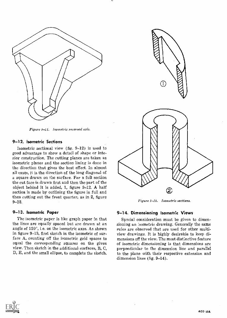
Figure 9-11. Isometric reversed axis.
9-12. Isometric SectionsIsometric sectional view (fig 9-12) is used to
good advantage to show a detail of shape or inte-rior construction. The cutting planes are taken asisometric planes and the section lining is done inthe direction that gives the best effect. In almostall cases, it is the direction of the long diagonal ofa square drawn on the surface. For a full sectionthe cut face is drawn first and then the part of theobject behind it is added, 1, figure 9-12. A halfsection is made by outlining the figure in full andthen cutting out the front quarter, as in 2, figure9-12.
9-13. Isometric PaperThe isometric paper is like graph paper in that
the lines are equally spaced but are drawn at anangle of 120', i.e. on the isometric axes. As shownin figure 9-13, first sketch in the isometric of sur-face A, counting off the isometric grid spaces toequal the corresponding squares on the givenview. Then sketch in the additional surfaces, B, C,D, E, and the small ellipse, to complete the sketch.
9-6
Figure 9-12. Isometric sections.
9-14. Dimensioning Isometric ViewsSpecial consideration must be given to dimen-
sioning an isometric drawing. Generally the samerules are observed that are used for other multi-view drawings. It is highly desirable to keep di-mensions off the view. The most distinctive featureof isometric dimensioning is that dimensions areperpendicular to the dimension line and parallelto the plane with their respective extension anddimension lines (fig. 9-14).
AGO 19A
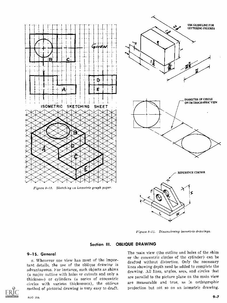
, 1_ F
ISOMETRIC SKETCHING SHEET
Figure 9-13. Sketching on isometric graph paper.
Section III.
USE GUIDELINE FORLETTERING FIGURES
DIAMETER OF CIRCLEON ORTHOGRAPHIC VIEW
REFERENCE CORNER
"T"
Figure 9-14. Dimensioning isometric drawings.
OBLIQUE DRAWING
9-15. Generala. Whenever one view has most of the impor-
tant details, the use of the oblique drawing isadvantageous. For instance, such objects as shims(a major outline with holes or cutouts and only athickness) or cylinders (a series of concentriccircles with various thicknesses), the obliquemethod of pictorial drawing is very easy to draft.
AGO 19A
The main view (the outline and holes of the shimor the concentric circles of the cylinder) can bedrafted without distortion. Only the necessarylines showing depth need be added to complete thedrawing. All lines, angles, arcs, and circles thatare parallel to the picture plane on the main vieware measurable and true, as :n orthographicprojection but not so on an isometric drawing.
9-7
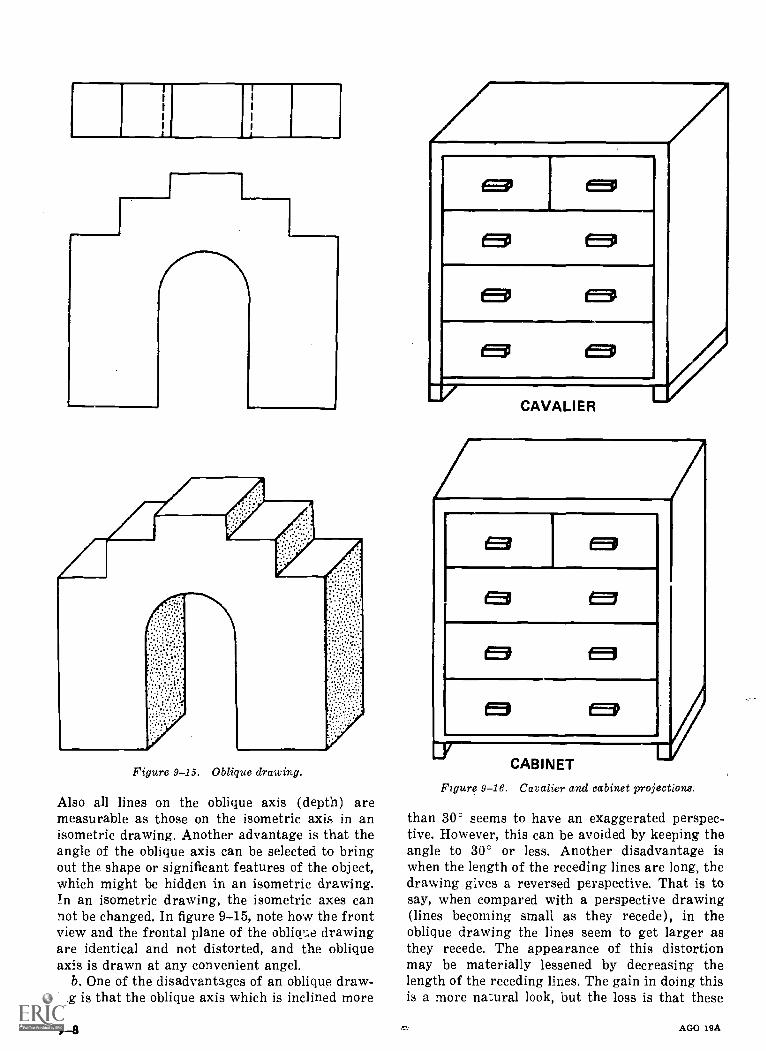
,_1
Figure 9-15. Oblique drawing.
Also all lines on the oblique axis (depth) aremeasurable as those on the isometric axis in anisometric drawing. Another advantage is that theangle of the oblique axis can be selected to bringout the shape or significant features of the object,which might be hidden in an isometric drawing.In an isometric drawing, the isometric axes cannot be changed. In figure 9-15, note how the frontview and the frontal plane of the oblioi,:e drawingare identical and not distorted, and the obliqueaxis is drawn at any convenient angel.
b. One of the disadvantages of an oblique draw-ing is that the oblique axis which is inclined more
9-8
1
E31 EEP
EEP
tEg
EEP
CAVALIER
631
CE5I
f.1
EEP
CABINET
Figure 9-16. Cavalier and cabinet projections.
than 30° seems to have an exaggerated perspec-tive. However, this can be avoided by keeping theangle to 300 or less. Another disadvantage iswhen the length of the receding lines are long, thedrawing gives a reversed perspective. That is tosay, when compared with a perspective drawing(lines becoming small as they recede), in theoblique drawing the lines seem to get larger asthey recede. The appearance of this distortionmay be materially lessened by decreasing thelength of the receding lines. The gain in doing thisis a more natural look, but the loss is that these
AGO 19A
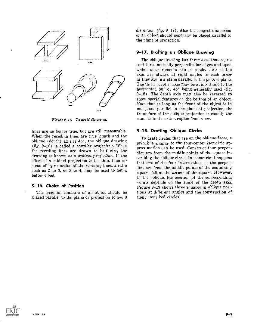
4
Figure 9-17. To avoid distortion.
lines are no longer true, but are still measurable.When the receding lines are true length and theoblique (depth) axis is 45°, the oblique drawing(fig. 9-16) is called a cavalier projection. Whenthe receding lines are drawn to half size, thedrawing is known as a cabinet projection. If theeffect of a cabinet projection is too thin, then in-stead of 1/2 reduction of the receding lines, a ratiosuch as 2 to 3, or 3 to 4, may be used to get abetter effect.
9-16. Choice of PositionThe essential contours of an object should be
placed parallel to the plane or projection to avoid
AGO 19A
distortion (fig. 9-17). Also the longest dimensionof an object should generally be placed parallel tothe plane of projection.
9-17. Drafting an Oblique Drawing
The oblique drawing has three axes that repre-sent three mutually perpendicular edges and uponwhich measurements can be made. Two of theaxes are always at right angles to each oLneras they are in a plane parallel to the picture plane.The third (depth) axis may be at any angle to thehorizontal, 30° or 45° being generally used (fig.9-18). The depth axis may also be reversed toshow special features on the bottom of an object.Note that as long as the front of the object is inone plane parallel to the plane of projection, thefront face of the oblique projection is exactly thesame as in the orthographic front view.
9-18. Drafting Oblique Circles
To draft circles that are on the oblique faces, aprinciple similar to the four-center isometric ap-proximation can be used. Construct four perpen-diculars from the middle points of the square in-scribing the oblique circle. In isometric it happensthat two of the four intersections of the perpen-diculars from the middle points of the containingsquare fall at the corner of the square. However,in the oblique, the position of the corresponding"'pints depends on the angle of the depth axis.teigure 9-19 shows three squares in oblique posi-tions at different angles and the construction oftheir inscribed circles.
9-9
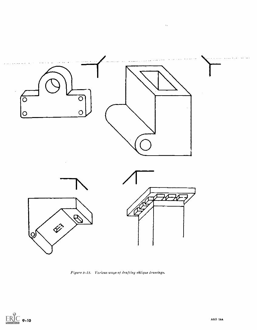
Figure 9-13. Various ways of drafting oblique drawings.
9TO AGO 18A
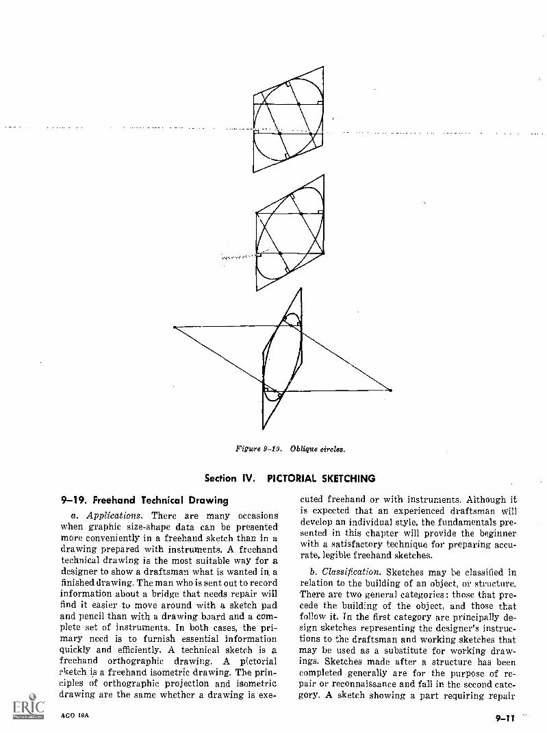
Figure 9-19. Oblique circlet).
Section IV. PICTORIAL SKETCHING
9-19. Freehand Technical Drawinga. Applications. There are many occasions
when graphic size-shape data can be presentedmore conveniently in a freehand sketch than in adrawing prepared with instruments. A freehandtechnical drawing is the most suitable way for adesigner to show a draftsman what is wanted in. afinished drawing. The man who is sent out to recordinformation about a bridge that needs repair willfind it easier to move around with a sketch padand pencil than with a drawing board and a com-plete set of instruments. In both cases, the pri-mary need is to furnish essential informationquickly and efficiently. A technical sketch is afreehand orthographic drawing. A pictorialketch is a freehand isometric drawing. The prin-
ciples of orthographic projection and isometricdrawing are the same whether a drawing is exe-
AGO 19A
cuted freehand or with instruments. Although itis expected that an experienced draftsman willdevelop an individual style, the fundamentals pre-sented in this chapter will provide the beginnerwith a satisfactory technique for preparing accu-rate, legible freehand sketches.
b. Classification. Sketches may be classified inrelation to the building of an object, or structure.There are two general categories : those that pre-cede the building of the object, and those thatfollow it. In the first category are principally de-sign sketches representing the designer's instruc-tions to the draftsman and working sketches thatmay be used as a substitute for working draw-ings. Sketches made after a structure has beencompleted generally are for the purpose of re-pair or reconnaissance and fall in the second cate-gory. A sketch showing a part requiring repair
9 -11
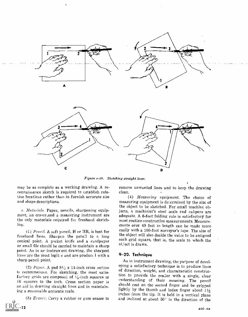
A
C
Figure d-20. Sketching
may be as complete as a working drawing. A re-connaissance sketch is required to cstablish rela-tive locations rather than to furnish accurate sizeand shape descriptions.
c. Materials. Paper, pencils, sharpening equip-ment, an eraser,and a measuring instrument arethe only materials required for freehand sketch-ing.
(1) Pencil. A soft pencil, H or HB, is best forfreehand lines. Sharpen the pencil to a longconical point. A pocket knife and a sandpaperor small file should be carried to maintain a sharppoint. As in au instrument drawing, the sharpestline:, are the most legib e and are product 1 with asharp pencil point.
(2) Paper. A pad 81A x 11-inch cross .3ectionis recommended. For sketching, the most satis-factory grids are composed of 14-inch squares or16 squares to the inch. Cross section paper isan aid in drawing straight lines and in maintain-ing a reasonable accurate scale.
(3) Eraser. Carry a rubber or g um eraser to
9-12
straight lines.
remove unwanted lines and to keep the drawingclean.
(4) Measuring equipment. The choice ofmeasuring equipment is de' ;ermined by the size ofthe object to be sketched. For small machine ob-jects, a machinist's steel scale and calipers areadequate. A 6-foot folding rule is satisfactory formost routine construction measurements. Measure-ments over 40 feet in length can be made moreeasily with a 100-foot surveyor's tape. The size ofthe object will also decide the value to be assignedeach grid square, that is, the scale to which theobject is drawn.
9-20. TechniqueAs in instrument drawing, the purpose of devel-
oping a satisfactory technique is to produce linesof direction, weight, and characteristic construc-tion to provide the reader with a single, clearunderstanding of their meaning. The pencilshould rest on the second finger and be grippedlightly by the thumb and index finger about 11/2inches from the tip. It is held in a vertical planeand inclined at about 30° in the direction of the
AGO 19A
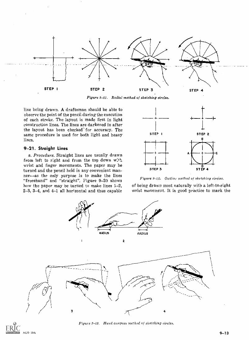
STEP I STEP 2 STEP 3
Figure 9-21. Radial method of sketching circles.
line being drawn. A draftsman should be able toobserve the point of the pencil during the executionof each stroke. The layout is made first in lightconstruction lines. The lines are darkened in afterthe layout has been checked- for accuracy. Thesame procedure is used for both light and heavylines.
9-21. Straight Linesa. Procedure. Straight lines are usually drawn
from left to right and from the top down withwrist and finger movements. The paper may beturned and the pencil held in any convenient man-neras the only purpose is to make the lines"freeehand" and "straight", Figure 9-20 showshow the paper may be turned to make lines 1-2,2-3, 3-4, and 4-1 all horizontal and thus capable
4-
STEP I
STEP 3
STEP 4
t
STEP 2
STEP 4
Figure 9-22. Outline method of sketching circies.
of being drawn most naturally with a left-to-rightwrist movement. It is good practice to mark the
RADIUS
AGO 19A
RADIUS
4
Figure 9-23. Hand compass method of sketching circles.
9-13
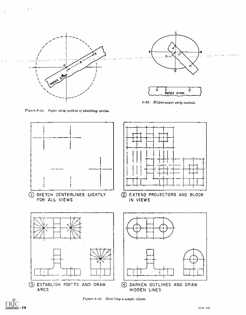
Figure 9-24. Paper strip method of sketching circles.
10 SKETCH CENTERLINES LIGHTLYFOR ALL VIEWS
® ESTABLISH POI"TS AND DRAWARCS
9-25. Ellipse-paper strip method.
0 EXTEND PROJECTORS AND BLOCKIN VIEWS
® DARKEN OUTLINES AND DRAWHIDDEN LINES
Figure 9-06. Skett ?ting a simple object.
9-14 AGO 19A
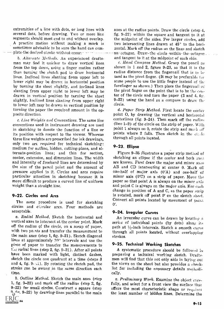
extremities of a line with dots, or long lines withseveral dots, before drawing. Two or more linesegments should meet end to end without overlap.A practice motion without making a mark issometimes advisable to be sure the hand can com
----plete-the -desi-red-streke- without -error:.b. Alternate Methods. An experienced drafts-
man may find it quicker to draw vertical linesfrom the top down, using a finger motion ratherthan turning the sketch pad to draw horizontallines. Inclined lines slanting from upper left tolower right may be drawn in horizontal positionby turning the sheet slightly, and inclined linesslanting from upper right to lower left may bedrawn in vertical position by turning the sheetslightly. Inclined lines slanting from upper rightto lower left may be drawn in vertical position byturning the paper the required amount in the op-posite direction.
c. Line Weights and Conventions. The same lineconventions used in instrument drawing are usedin sketching to denote the function of a line orits position with respect to the viewer. Whereasthree line weights are prescribed for ink drawings,only two arc required for technical sketching:medium for outline, hidden, cutting-plane, and al-ternate-position lines; and thin for section,center, extension, and dimension lines. The widthand intensity of freehand lines are determined bythe. size of the pencil point and the amount ofpressure applied to it. Circles and arcs requireparticular attention in sketching because it ismore difficult to produce a curved line of uniformweight than a straight line.
9-22. Circles and ArcsThe same procedure is used for sketching
circles and cii-cular arcs. Four methods areacceptable.
a. Radial Method. Sketch the horizontal andvertical axes to intersect at the center point. Markoff the radius of the circle, on a scrap of paper,with two points and transfer the measurement tothe main axes (step 1, fig. 9-21). Sketch diagonallines at approximately intervals and use thepiece of paper to transfer the measurements totae radial lines (step 2, fig. 9-21). After all pointshave been marked with light, distinct dashes,sketch the circle one quadrant at a time (steps 3and 4, fig. 9- By rotating the sketch pad, thestroke can be swung in the same direction eachtime.
b. Outline Method. Sketch the main axes (step1, fig. 9-22)-and mark off the radius (step 2, fig.9-22) for small circles. Construct a square (step3, fig. 9-22) by drawinglines parallel to the main
AGO 19A
axes at the radius points. Draw the circle (step 4,fig. 9-22) within the square and tangent to it atthe midpoint of the sides. For larger circles, addtwo intersecting lines drawn at 450 to the hori-zontal. Mark off the radius on the lines and sketch-an octagon. Draw the-- c irale withinthe -octagonand tangent to it at the midpoint of each side.
c. Hand Compass Method. Grasp the pencil asshown in 1 and 2, figure 9-23, so that it is theradius distance from the fingernail that is to heused as the pivot finger. (It may be preferable forsome people to use the little finger instead of theforefinger as shown.) Then place the fingernaii ofthe pivot finger on the point that is to be the een-ter of the circle and turn the paper (3 and 4, fig.9-23) using the hand as a compass to draw theircle.
d. Paper Strip Method. First locate the centerpoint 0, by drawing the vertical and horizontalcenterlines (fig. 9-24). Then mark off the radius(line. 1-2) of the circle on the strip of paper. Withpoirit 1 always on 0, rotate the strip and mi.! kpoints where 2 falls. Then sketch in the ei:through all points located.
9-23. EllipseFigure 9-25 illustrates a paper strip method of
sketching an ellipse if the center and both axe.;are known. First draw the major and minor axesAB and CD intersecting at center 0. Mark oil'one-half of major axis (0'A) and one-half ofminor axis (O'C) on a strip of paper. Move the.paper so that point A is always en the minor axisand point C is always on the major axis. Kor tattlichange in position of A and C, as the paper stripis rotated, mark off point 0' on the sketch sheet.Connect all points located by movement of point0'
9-24. Irregular CurvesAn irregular curve can be drawn by locatiDg
series of individual points (by dots) alongpath at 1/4-inch intervals. Sketch a smooth curvethrough all points located, without overlappingstrokes.
9-25. Technical Working SketchesA systematic procedure should be followed in
preparing a technical wort ing sketch. Drafts-men will find that this not only aids in laying outthe views on the sheet but also provides a check-list for including the necessary details methodi-cally.
a. Preliminary Work. Examine the object care-fully, and select for a front view the surface thatoffers the most characteristic shape or requiresthe least number of hidden lines. Determine the
9-15
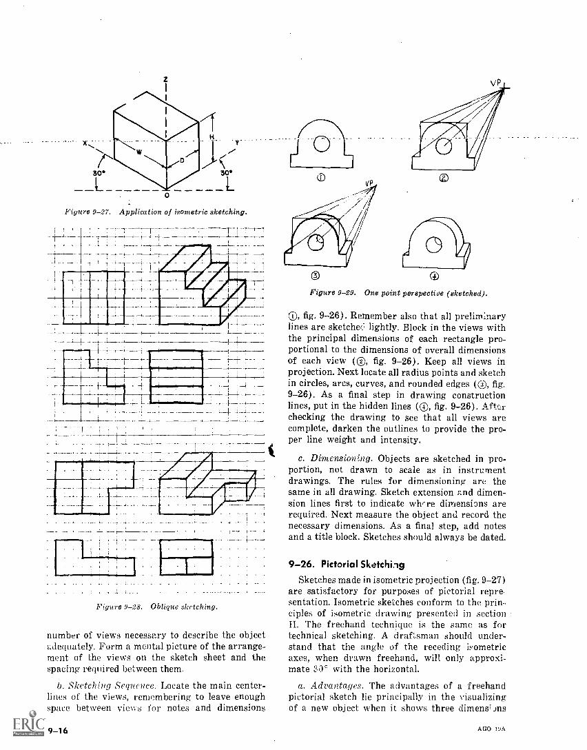
Figure 9-27. Application of isometric sketching.
,I
1 1
-4;
--I- , ,-
. .._i f. .
.
__i_ .., ,
I
Figure 9-28. Oblique sketching.
number of views necessary to describe the objectadequately. Form a mental picture of the arrange-ment of the views on the sketch sheet and thespacing required between them.
b. Sketching Sequence. Locate the main center-lines of the views, remembering to leave enoughspace between views for notes and dimensions
9-16
0 (4)
Figure 9-29. One point perspective (sketched).
®, fig. 9-26). Remember also that all prelirn:narylines are sketched lightly. Block in the views withthe principal dimensions of each rectangle pro-portional to the dimensions of overall dimensionsof each view (C), fig. 9-26). Keep all views inprojection. Next locate all radius points and sketchin circles, arcs, curves, and rounded edges (®, fig.9-26). As a final step in drawing constructionlines, put in the hidden lines (C), fig. 9-26). After
checking the drawing to see that all views arecomplete, darken the outlines to provide the pro-per line weight and intensity.
c. Dimensionng. Objects are sketched in pro-portion, not drawn to scale as in instrumentdrawings. The rules for dimensioning are thesame in all drawing. Sketch extension ^,nd dimen-sion lines first to indicate where dimensions arerequired. Next measure the object and record thenecessary dimensions. As a final step, add notesand a title block. Sketches should always be dated.
9-26. Pictorial SketchingSketches made in isometric projection (fig. 9-27)
are satisfactory for purposes of pictorial repre-sentation. Isometric sketches conform to the prin-ciples of isometric drawing presented in sectionII. The freehand technique is the same as fortechnical sketching. A draftsman should under-stand that the angle of the receding isometricaxes, when drawn freehand, will only approxi-mate 30° with the horizontal.
a. Advantages. The advantages of a freehandpictorial sketch lie principally in the visualizingof a new object when it shows three dimens' ins
AGO 19A
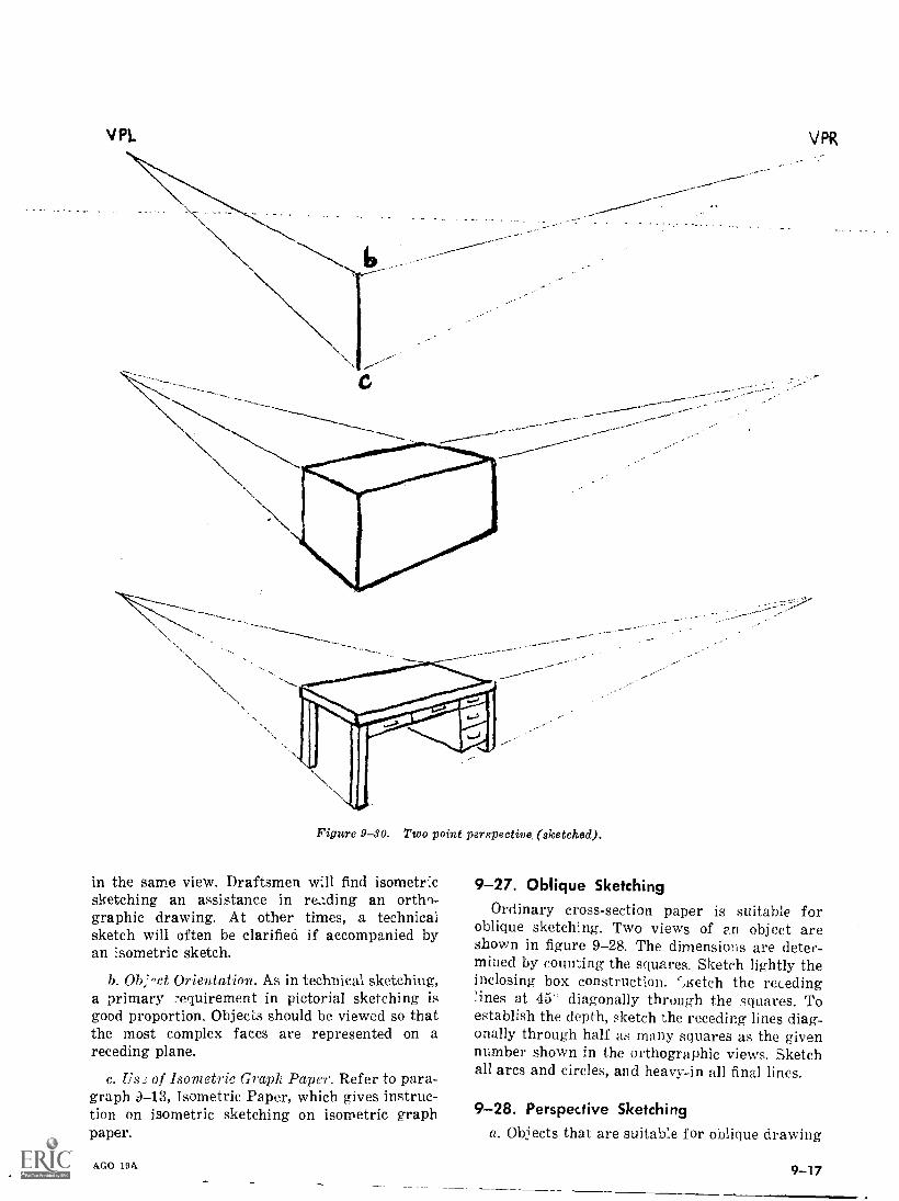
VPL VPR
Figure 9SO. Two point perspective, (sketched).
in the same view. Draftsmen will find isometricsketching an assistance in reading an ortho-graphic drawing. At other times, a technicalsketch will often be clarified if accompanied byan isometric sketch.
b. Ob,'-ct Orientation. As in technical sketching,a primary ...equirement in pictorial sketching isgood proportion. Objects should be viewed so thatthe most complex faces are represented on areceding plane.
c. Us: of Isometric Graph Paper. Refer to para-graph 13, Isometric Paper, which gives instruc-tion on isometric sketching on isometric graphpaper.
AGO 19A
9-27. Oblique SketchingOrdinary cross-section paper is suitable for
oblique sketching. Two views of an object areshown in figure 9-28. The dimensions are deter-mined by counting the squares. Sketch lightly theinclosing box construction. ',Ketch the receding'fines at 45' diagonally through the squares. Toestablish the depth, sketch the receding lines diag-onally through half as many squares as the givennumber shown in the orthographic views. Sketchall arcs and circles, and heavy-in all final lines.
9-28. Perspective Sketchinga. Objects that are suitable for oblique drawing
9 -17
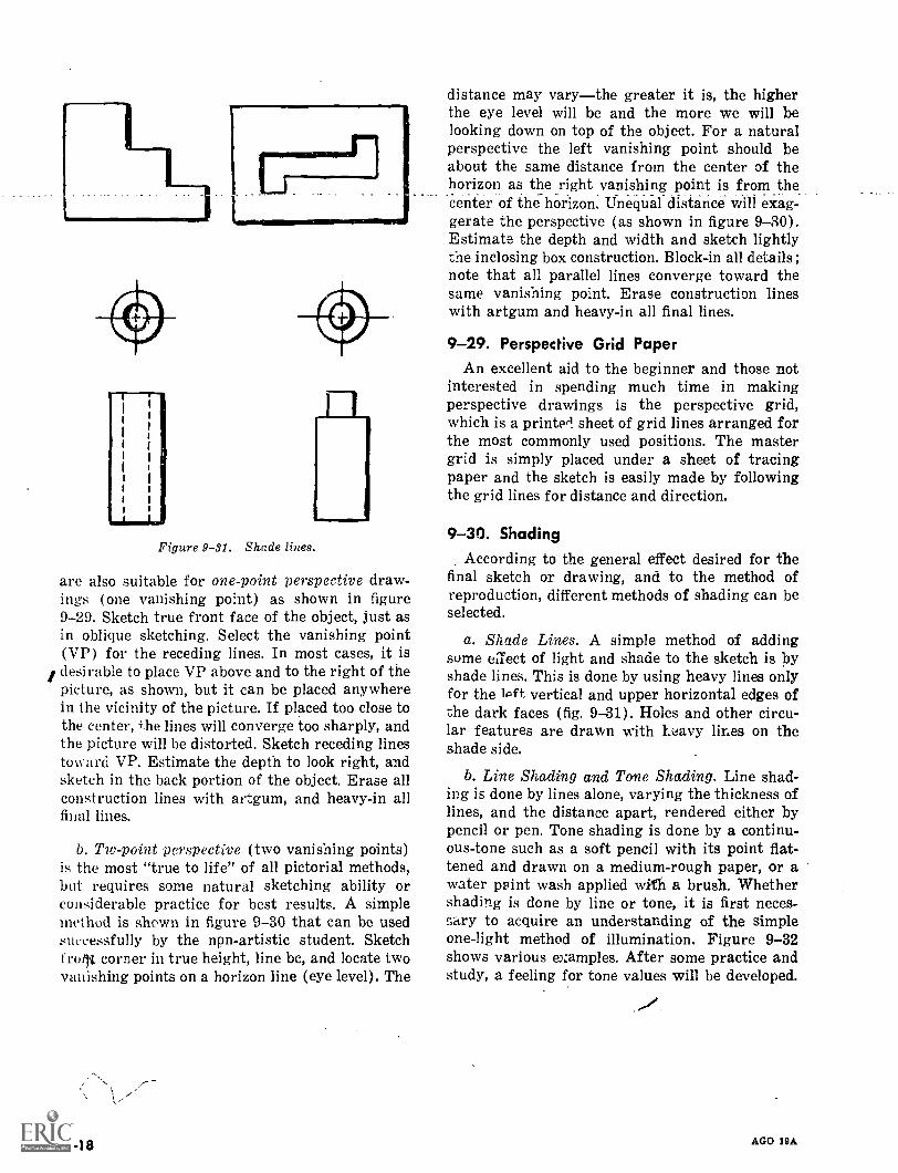
Figure 9-31. Shade lines.
are also suitable for one-point perspective draw-ings (one vanishing point) as shown in figure9-29. Sketch true front face of the object, just asin oblique sketching. Select the vanishing point(VP) for the receding lines. In most cases, it isdesirable to place VP above and to the right of thepicture, as shown, but it can be placed anywherein the vicinity of the picture. If placed too close tothe center, the lines will converge too sharply, andthe picture will be distorted. Sketch receding linestoward VP. Estimate the depth to look right, andsketch in the back portion of the object. Erase allconstruction lines with artgum, and heavy-in allfinal lines.
b. Tiv-point perspective (two vanishing points)is the most "true to life" of all pictorial methods,but requires some natural sketching ability orconsiderable practice for best results. A simplemethod is shown in figure 9-30 that can be usedsuccessfully by the npn-artistic student. Sketchfruilit corner in true height, line bc, and locate twovanishing points on a horizon line (eye level). The
9 -18
distance may varythe greater it is, the higherthe eye level will be and the more we will belooking down on top of the object. For a naturalperspective the left vanishing point should beabout the same distance from the center of thehorizon as the right vanishing point is from the
. . _
center of the horizon. Unequal distance will exag-gerate the perspective (as shown in figure 9-30).Estimate the depth and width and sketch lightlythe inclosing box construction. Block-in all details;note that all parallel lines converge toward thesame vanishing point. Erase construction lineswith artgum and heavy-in all final lines.
9-29. Perspective Grid PaperAn excellent aid to the beginner and those not
interested in spending much time in makingperspective drawings is the perspective grid,which is a printed sheet of grid lines arranged forthe most commonly used positions. The mastergrid is simply placed under a sheet of tracingpaper and the sketch is easily made by followingthe grid lines for distance and direction.
9-30. ShadingAccording to the general effect desired for the
final sketch or drawing, and to the method ofreproduction, different methods of shading can beselected.
a. Shade Lines. A simple method of addingsome effect of light and shade to the sketch is byshade lines. This is done by using heavy lines onlyfor the lat vertical and upper horizontal edges ofthe dark faces (fig. 9-31). Holes and other circu-lar features are drawn with hc.avy lines on theshade side.
b. Line Shading and Tone Shading. Line shad-ing is done by lines alone, varying the thickness oflines, and the distance apart, rendered either bypencil or pen. Tone shading is done by a continu-ous-tone such as a soft pencil with its point flat-tened and drawn on a medium-rough paper, or awater paint wash applied width a brush. Whethershading is done by line or tone, it is first neces-sary to acquire an understanding of the simpleone-light method of illumination. Figure 9-32shows various examples. After some practice andstudy, a feeling for tone values will be developed.
AGO 19A
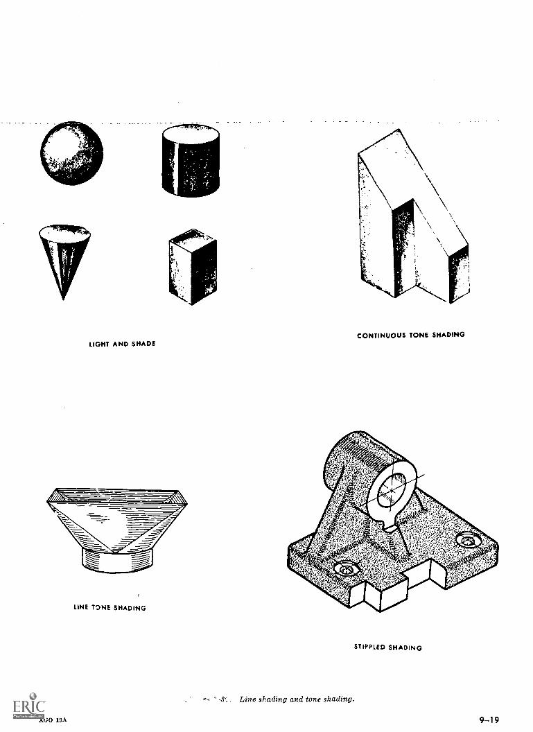
LIGHT AND SHADE
LINE TONE SHADING
AGO 19A
CONTINUOUS TONE SHADING
Line shading and tone shading.
STIPPLED SHADING
9-.19
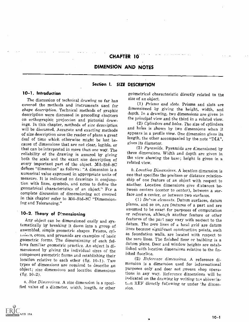
CHAPTER 10
DIMENSION AND NOTES
Section I. SIZE DESCRIPTION
10-1. IntroductionThe discussion of technical drawing so far has
covered the methods and instruments used forshape description. Technical methods of graphicdescription were discussed in preceding chapterson orthographic projection and pictorial draw-ings. In this chapter, methods of size descriptionwill be discussed. Accurate and exacting methodsof size description save the reader of plans a greatdeal of time which otherwise might be lost be-cause of dimensions that are not clear, legible, orthat can be interpreted in more than one way. Thereliability of the drawing is assured by givingboth the scale and the exact size description ofevery important part of the object. MilStd-8Cdefines "dimension" as follows : "A dimension is anumerical value expressed in appropriate units ofmeasure. It is indicated on drawings in conjunc-tion with lines, symbols, and notes to define thegeometrical characteristics of an object." Fcr acomplete discussion of dimensioning net coveredin this chapter refer to MilStd-8C "Dimension-ing and Tolerancing."
10-2. Theory of D ?-pensioning
Any object can be dimensioned easily and sys-tematically by breaking it down into a group ofassembled, simple geometric shapes. Prisms, cyl-iiitIcfs, cones, and pyramids are examples of basicgeometric forms. The dimensioning of each fol-lows familiar geometric practice. An object is di-mensioned by giving the individual sizes of thecomponent geometric forms and establishing theirlocation relative to each other (fig. 10-1). Twotypes of dimensions are required to describe anobject; size dimensions and location dimensions(fig. 10-2).
a. Size Dimensions, A size dimension is a speci-fied value of a diameter, width, length, or other
AGO 19A
geometrical characteristic directly related to thesize of an object.
(1) Prisms and slots. Prisms and slots aredimensioned by giving the height, width, anddepth. In a drawing, two dimensions are given inthe principal view and the third in a related view.
(2) Cylinders and holes. The size of cylindersand holes is shown by two dimensions when itappears in a profile view. One dimension gives itslength, the other accompanied by the note "DIA",gives its diameter.
(3) Pyramids. Pyramids are dimensioned bythree dimensions. Width and depth are given inthe view showing the base; height is given in arelated view.
b. Location. Dimensions. A location dimension isone that specifies the position or distance relation-ship of one feature of an object with respect toanother. Location dimensions give distances be-tween centers (center to center), between a sur-face and a center, or between two surfaces.
(1) Delon, elements. Datum surfaces, datumplanes, and so on, are features of a part and areassumed to be exact for purposes of computationor reference, although another feature or otherfeatures of the part may vary with respect to thedatum. The zero lines of a local grid are datumlines because significant construction points, suchas foundation walls, are located with respect tothe zero lines. The finished floor or building is adatum plane. Door and window heights are estab-lished with location dimensions relative to the fin-ished floorline.
(2) Reference dimensions. A reference di-mension is a dimension used for informationalpurposes only and does not govern shop opera-tions in any way. Reference dimensions will beindicated on the drawing by writing tue abbrevia-ton REF directly following or under the dimen-sion.
10 -1
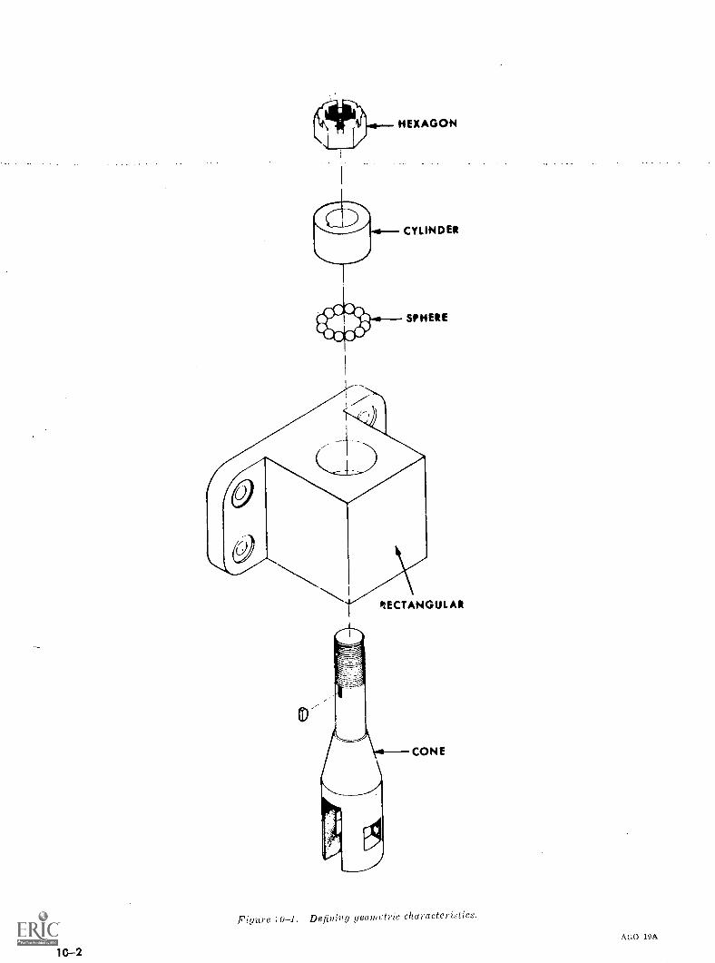
RECTANGULAR
Figure 10-1. Defining geometric characteristics.
AGO 19A
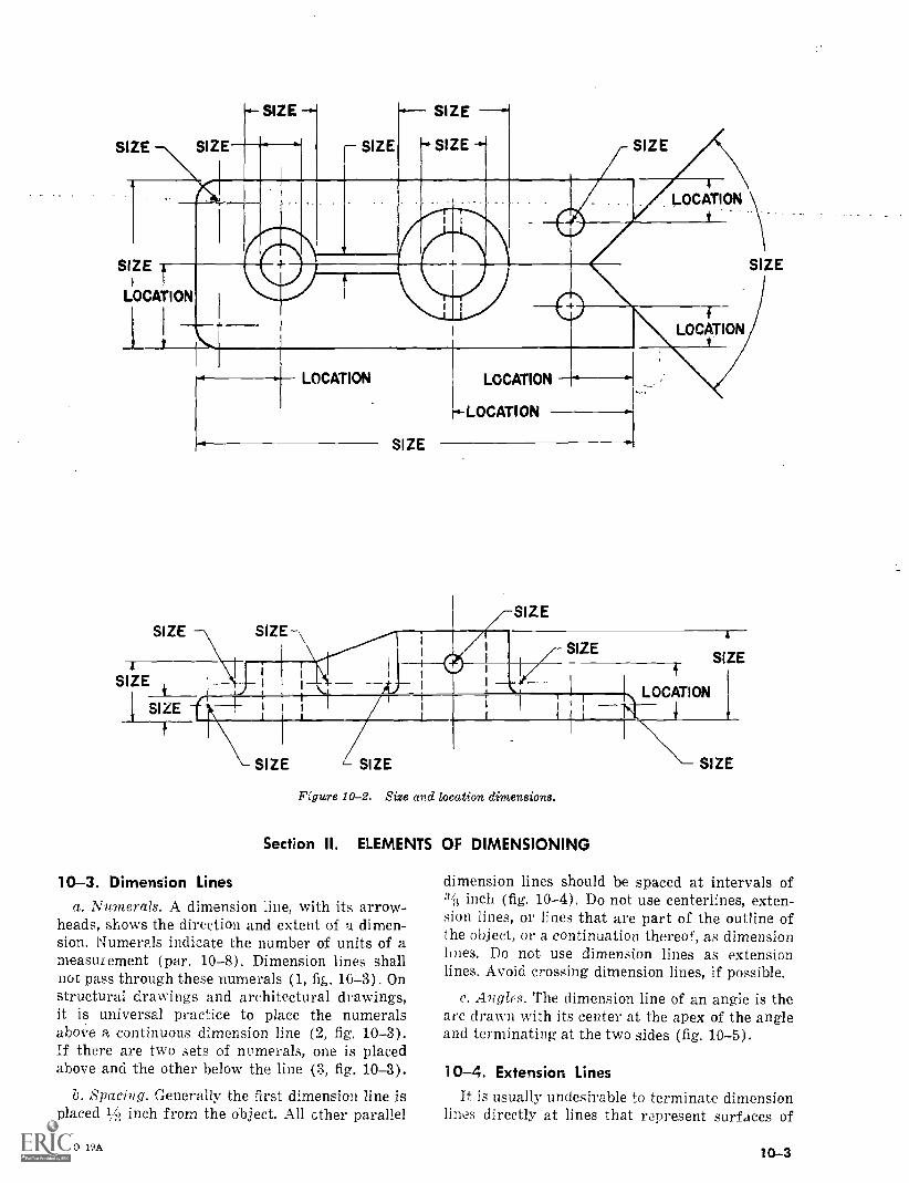
4 SIZE
SIZE
SIZE
LOCATION
LOCATION
SIZE
LOCATION
SIZE
LOCATION
SIZE
SIZE
SIZEI
SIZE
LOCATION
r.-LOCATION
SIZE
SIZE
N.4
SIZE
LOCATION
SIZE L SIZE
Figure 10-2. Size and location dimensions.
Section II. ELEMENTS OF DIMENSIONING
10-3. Dimension Linesa. Numerals. A dimension line, with its arrow-
heads, shows the direction and extent of a dimen-sion. Numerals indicate the number of units of ameasurement (par. 10-8). Dimension lines shallnot pass through these numerals ( 1, fig. 10-3). Onstructural drawings and architectural drawings,it is universal practice to place the numeralsabove a continuous dimension line (2, fig. 10-3).If there are two sets of numerals, one is placedabove and the other below the line (3, fig. 10-3).
b. Spacing. Generally the first dimension line isplaced 1 inch from the object. All ether parallel
AGO 19A
SIZE
dimension lines should be spaced at intervals ofinch (fig. 10-4). Do not use centerlines, exten-
sion lines, or lines that are part of the outline ofthe object, or a continuation thereof, as dimensionlines. Do not use dimension lines as extensionlines. Avoid crossing dimension lines, if possible.
c. Angles. The dimension line of an angle is thearc drawn with its center at the apex of the angleand terminating at the two sides (fig. 10-5).
10-4. Extension LinesIt is usually undesirable to terminate dimension
lines directly at lines that represent surfaces of
10-3
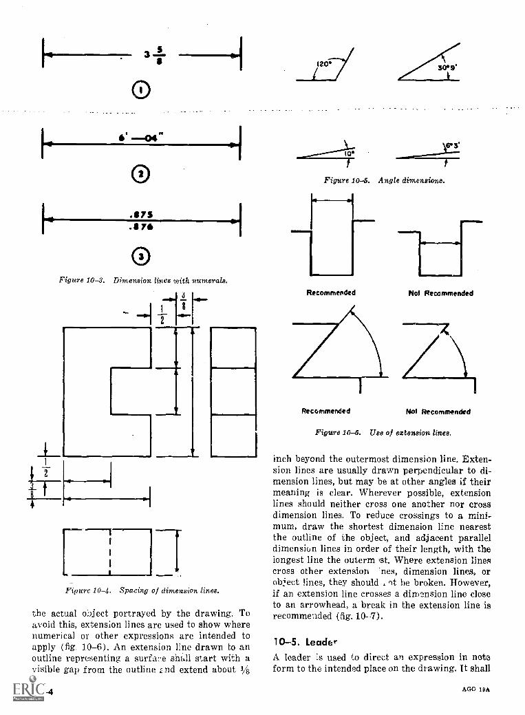
O
.$7S.11711
OFigure 10-3. Dimension lines with numerals.
t4
Figure 10-4. Spacing of dimension lines.
the actual object portrayed by the drawing. Toavoid this, extension lines are used to show wherenumerical or other expressions are intended toapply (fig 10-6). An extension line drawn to anoutline representing a surface shall start with avisible gap from the outline .,nd extend about 1/8
10-4
120 3069.
63'10T
Figure 10-5. Angle dimensions.
Recommended
.111MNI
AlmllNot Recommended
Recommended Not Recommended
Figure 10-6. Use of extension lines.
inch beyond the outermost dimension line. Exten-sion lines are usually drawn perpendicular to di-mension lines, but may be at other angles if theirmeaning is clear. Wherever possible, extensionlines should neither cross one another nor crossdimension lines. To reduce crossings to a mini-mum, draw the shortest dimension line nearestthe outline of the object, and adjacent paralleldimension lines in order of their length, with thelongest line the outerm st. Where extension linescross other extension 'nes, dimension lines, orobject lines, they should of be broken. However,if an extension line crosses a dimension line closeto an arrowhead, a break in the extension line isrecommended (fig. 10-7).
10-5. LeaderA leader is used to direct an expression in noteform to the intended place on the drawing. It shall
AGO 19A
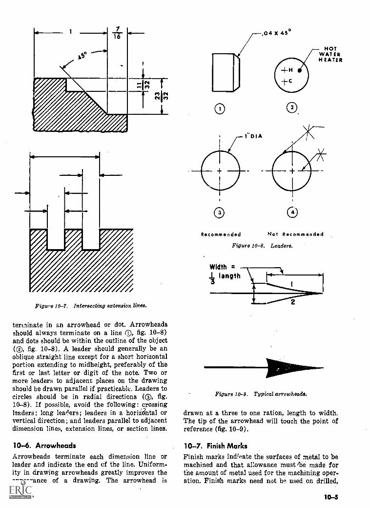
17
16.11.
N" eq
Figure 10-7. Intersecting extension lines.
terminate in an arrowhead or dot. Arrowheadsshould always terminate on a line @, fig. 10-8)and dots should be within the outline of the object(C), fig. 10-8). A leader should generally be anoblique straight line except for a short horizontalportion extending to midheight, preferably of thefirst or last letter or digit of the note. Two ormore leaders to adjacent places on the drawingshould be drawn parallel if practicable. Leaders tocircles should be in radial directions (C), fig.10-8). If possible, avoid the following : ,crossingleaders ; long learlers ; leaders in a horizdntal orvertical direction ; and leaders parallel to adjacentdimension lines, extension lines, or section lines.
10-6. ArrowheadsArrowheads terminate each dimension line orleader and indicate the end of the line. Uniform-ity in drawing arrowheads greatly improves theappearance of a drawing. The arrowhead is
AGO 19A
O O
HOTWAT ERH EATER
Recommended Not Recommended
Figure 10-8. Leaders.
Widthlength
2
Figure 10-9. Typical arrowheads.
drawn at a three to one ration, length to width.The tip of the arrowhead will touch the point ofreference (fig. 10-9).
10-7. Finish MarksFinish marks indicate the surfaces of metal to bemachined and that allowance must .13e made forthe amount of metal used for the machining oper-ation. Finish marks need not be used on drilled,
10-5
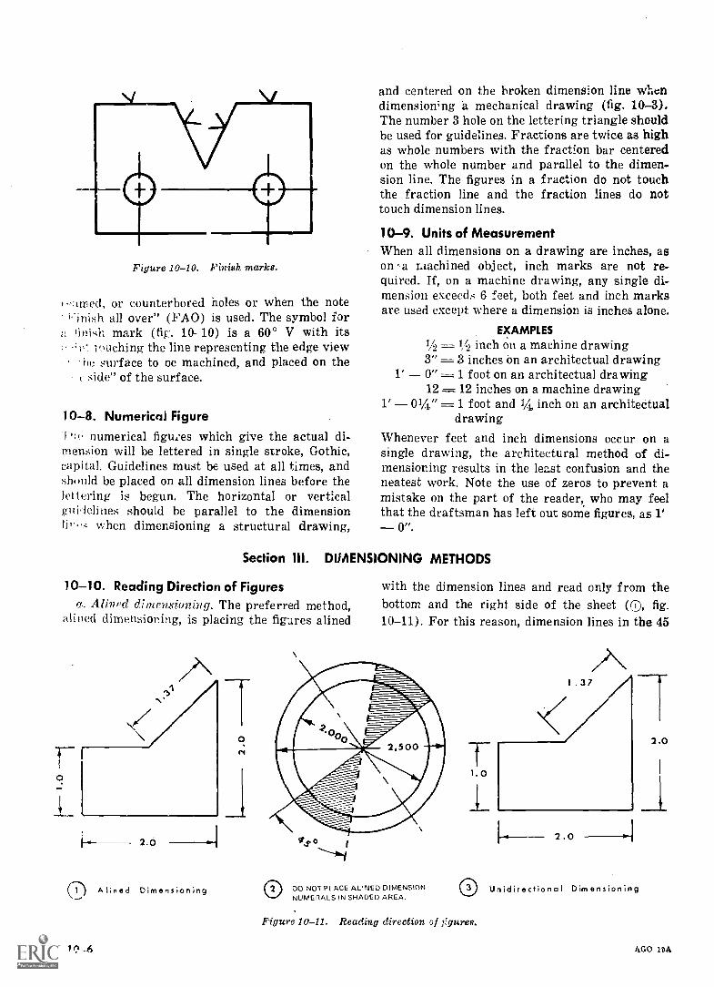
Figure 10-10. Finish marks.
.rimed, or counterbored holes or when the noteFinish all over" (FAO) is used. The symbol forfinish mark (fig.. 10-10) is a 60° V with its
tuching the line representing the edge viewhe surface to oe machined, and placed on the
r side" of the surface.
10-8. Numerical Figurenumerical figures which give the actual di-
mension will be lettered in single stroke, Gothic,capital. Guidelines must be used at all times, andshuuld be placed on all dimension lines before thelettering is begun. The horizontal or verticalguidelines should be parallel to the dimensionlip when dimensioning a structural drawing,
and centered on the broken dimension line whendimensioning a mechanical drawing (fig. 10-3).The number 3 hole on the lettering triangle shouldbe used for guidelines. Fractions are twice as highas whole numbers with the fraction bar centeredon the whole number and parallel to the dimen-sion line. The figures in a fraction do not touchthe fraction line and the fraction lines do nottouch dimension lines.
10-9. Units of MeasurementWhen all dimensions on a drawing are inches, ason -a Liachined object, inch marks are not re-quired. If, on a machine drawing, any single di-mension exceeds, 6 feet, both feet and inch marksare used except where a dimension is inches alone.
EXAMPLES1/2 = 1,!, inch on a machine drawing3", 3 inches On an architectual drawing
1' 0" = 1 foot on an architectual drawing12 = 12 inches on a machine drawing
1' 01/4" = 1 foot and 1/4, inch on an architectualdrawing
Whenever feet and inch dimensions occur on asingle drawing, the architectural method of di-mensioning results in the least confusion and theneatest work. Note the use of zeros to prevent amistake on the part of the reader, who may feelthat the draftsman has left out some figures, as 1'
0".
Section 111. DIMENSIONING METHODS
10-10. Reading Direction of Figuresa. Alined dimensioning. The preferred method,
alined dimensioning, is placing the figures alined
0
2.6
.--1) Alined Dimensioning
with the dimension lines and read only from thebottom and the right side of the sheet (CO, fig.10-11). For this reason, dimension lines in the 45
DO NOT PLACE ALINED DIMENSIONNUMERALS IN SHADED AREA.
Figure 10-11. Reading direction "if ;figures.
2.0
Unidirectional Dimensioning
AGO 19A
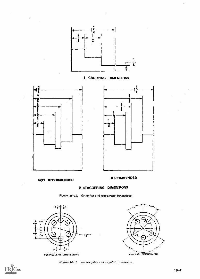
A
NOT RECOMMENDED
1 GROUPING DIMENSIONS
RECOMMENDED
2 STAGGERING DIMENSIONS
Figure 10-42. Grouping and staggering dimensions.
RECTANGULAR DIMENSIONING
I Z REF
6C?
ANGULAR DIMENSIONING
Figure 10-13. Rectangular and angular dimensions.
AGO 19A 10-7
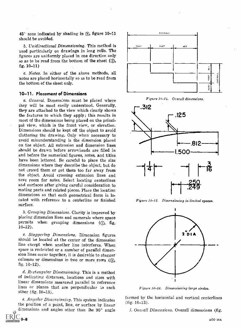
45' zone indicated by shading in ®, figure 10-11should be avoided.
b. Unidirectional Dimensioning. This method isused particularly on drawings in long rolls. Thefigures are uniformly placed in one direction onlyso as to be read from the bottom of the sheet (C),fig. 10-11)
c. Notes. In either of the above methods, allnotes are placed horizontally so as to be read fromthe bottom of the sheet only.
10-11. Placement of Dimensionsa. General. Dimensions must be placed where
they will be most easily understood. Generally,they are attached to the view which clearly showsthe features to which they apply ; this results inmost of the dimensions being placed on the princi-pal view, which is the front view, or elevation.Dimensions should be kept off the object to avoidcluttering the drawing. Only when necessary toavoid misunderstanding is the dimension placedon the object. All extension and dimension linesshould be drawn before arrowheads are filled inand before the numerical figures, notes, and titleshave been lettered. Be careful to place the sizedimensions where they describe the object, but donot crowd them or get them too far away fromthe object. Avoid crossing extension lines andsave room for notes. Select locating centerlinesand surfaces after giving careful consideration tomating parts and related pieces. Place the locationdimensions so that each geometrical form is lo-cated with reference to a centerline or finishedsurface.
b. Grouping Dimensions. Clarity is improved byplacing dimension lines and numerals where spacepermits when grouping dimensions (C), fig.10-12).
c. Staggering Dimensions. Dimension figuresshould be located at the center of the dimensionline except when another line interferes. Whenspace is restricted or a number of parallel dimen-sion lines occur together, it is desirable to staggercolumns or dimensions in two or more rows (C),fig. 10-12).
d. Rectangular Dimensioning. This is a methodof indicating distances, locations and sizes withlinear dimensions measured parallel to referencelines or planes that are perpendicular to eachother (fig. 10-13).
e. Angular Dimensioning. This system indicatesthe position of a point, line, or surface by lineardimensions and angles other than the 90° angle
10-8
OVERALL
PART PART REF
ti
cc
>O
Figure 10-14. Overall dimensions.
.312
Figure 10-15. Dimensioning in limited spaces.
Figure 10-16. Dimensioning large circles.
formed by the horizontal and vertical centerlines(fig. 10-13).
f. Overall Dimensions. Overall dimensions (fig.
AGO 19A
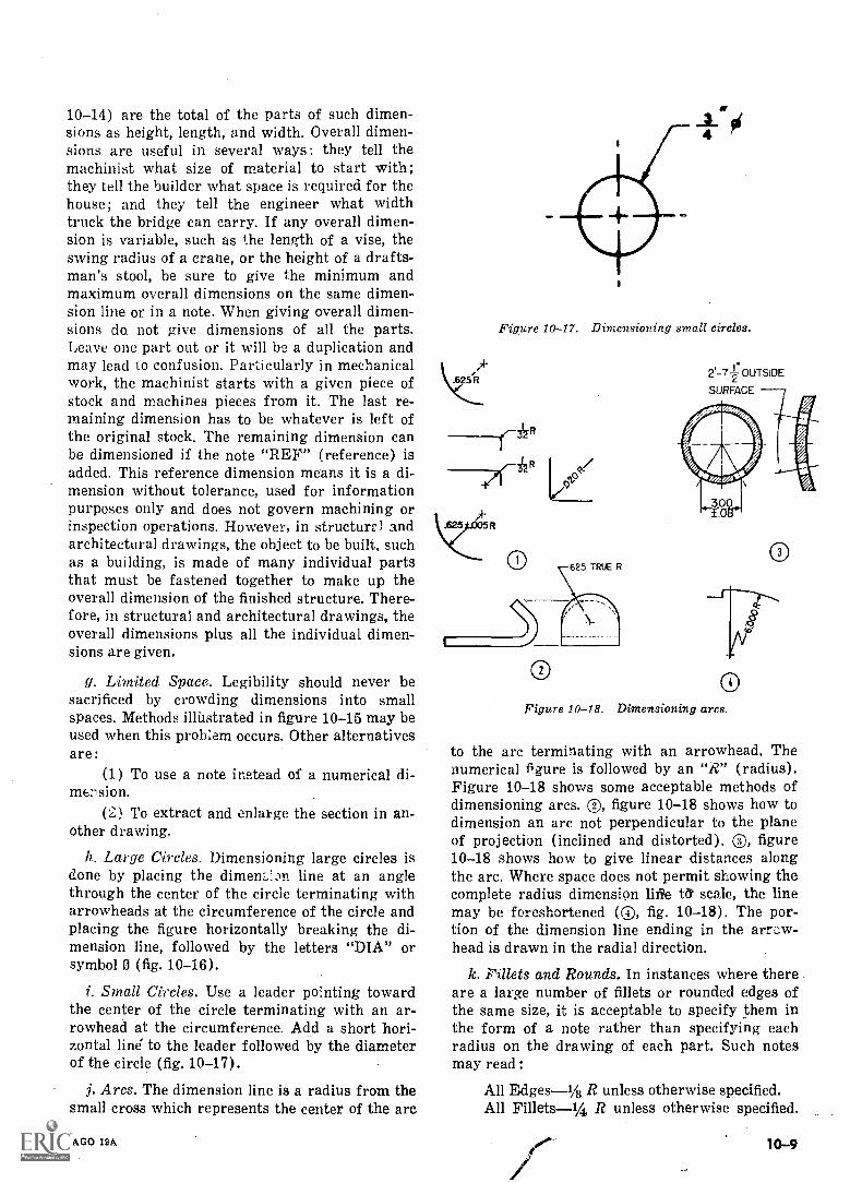
10-14) are the total of the parts of such dimen-sions as height, length, and width. Overall dimen-sions are useful in several ways: they tell themachinist what size of material to start with;they tell the builder what space is required for thehouse; and they tell the engineer what widthtruck the bridge can carry. If any overall dimen-sion is variable, such as the length of a vise, theswing radius of a crane, or the height of a drafts-man's stool, be sure to give the minimum andmaximum overall dimensions on the same dimen-sion line or in a note. When giving overall dimen-sions do. not give dimensions of all the parts.Leave one part out or it will be a duplication andmay lead to confusion. Particularly in mechanicalwork, the machinist starts with a given piece ofstock and machines pieces from it. The last re-maining dimension has to be whatever is left ofthe original stock. The remaining dimension canbe dimensioned if the note "REF" (reference) isadded. This reference dimension means it is a di-mension without tolerance, used for informationpurposes only and does not govern machining orinspection operations. However, in structure' andarchitectural drawings, the object to be built, suchas a building, is made of many individual partsthat must be fastened together to make up theoverall dimension of the finished structure. There-fore, in structural and architectural drawings, theoverall dimensions plus all the individual dimen-sions are given.
g. Limited Space. Legibility should never besacrificed by crowding dimensions into smallspaces. Methods illustrated in figure 10-15 may beused when this problem occurs. Other alternativesare:
(1) To use a note instead of a numerical di-mension.
(2) To extract and enlarge the section in an-other drawing.
h. Large Circles. Dimensioning large circles isdone by placing the dimem,In line at an anglethrough the center of the circle terminating witharrowheads at the circumference of the circle andplacing the figure horizontally breaking the di-mension line, followed by the letters "DIA" orsymbol 0 (fig. 10-16).
i. Small Circles. Use a leader pointing towardthe center of the circle terminating with an ar-rowhead at the circumference. Add a short hori-zontal line to the leader followed by the diameterof the circle (fig. 10-17).
j. Arcs. The dimension line is a radius from thesmall cross which represents the center of the arc
AGO 19A
Figure 10-17. Dimensioning small circles.
b25 R
do
2'-7-fOUTSIDE2SURFACE
0Figure 10-18. Dimensioning arcs.
to the arc terminating with an arrowhead. Thenumerical figure is followed by an "R" (radius).Figure 10-18 shows some acceptable methods ofdimensioning arcs. ®, figure 10-18 shows how todimension an arc not perpendicular to the planeof projection (inclined and distorted). C), figure10-18 shows how to give linear distances alongthe arc. Where space does not permit showing thecomplete radius dimension lift 0' scale, the linemay be foreshortened (C), fig. 10-18). The por-tion of the dimension line ending in the arn;w-head is drawn in the radial direction.
k. Fillets and Rounds. In instances where thereare a large number of fillets or rounded edges ofthe same size, it is acceptable to specify them inthe form of a note rather than specifying eachradius on the drawing of each part. Such notesmay read:
All Edges-1/2 R unless otherwise specified.All Fillets-1/4 R unless otherwise specified.
10-9
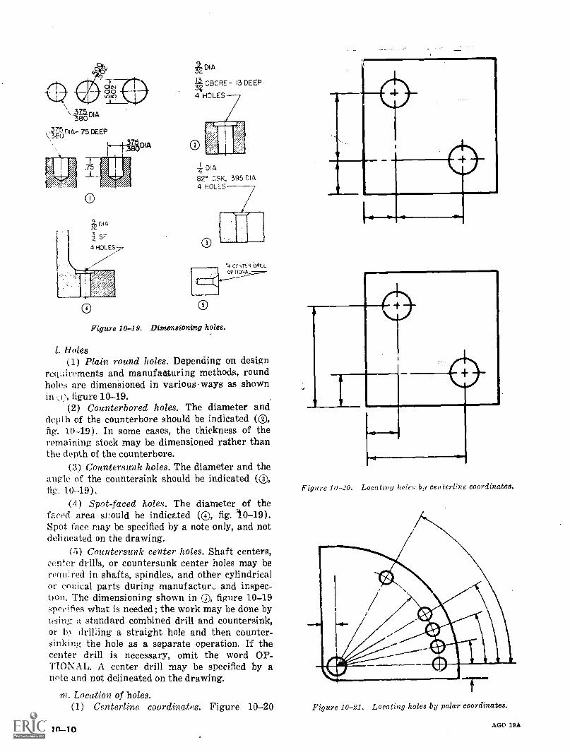
"0-\ .3375 DIA80
.i78ijD1A- 75 DEEP
DIA
Figure 10-19.
DIA
3?CBORE- 13 DEEP
4 HOLES
a1
Df A
82° OSK, 395 0144 HOLES
a
O
Dimensioning holes.
.4 CENTER DRILLOP TIONA
I. Holes(1) Plain round holes. Depending on design
rectLiirements and manufaAturing methods, roundholes are dimensioned in various.ways as shown
figure 10-19.(2) Counterbored holes. The diameter and
depth of the counterbore should be indicated (C),fig. 10-19). In some cases, the thickness of theremaining stock may be dimensioned rather thanthe depth of the counterbore.
(3) Countersank holes. The diameter and theangle of the countersink should be indicated (®,fig. 10-19).
(4) Spot-faced holes. The diameter of thefaced area should be indicated (0, fig. 1.0-19).Spot face may be specified by a note only, and notdelineated on the drawing.
(5) Countersunk center holes. Shaft centers,center drills, or countersunk center holes may berequired in shafts, spindles, and other cylindricalor conical parts during manufactun and inspec-tion. The dimensioning shown in ®, figure 10-19specifies what is needed; the work may be done byusing a standard combined drill and countersink,or In drilling a straight hole and then counter-sinking the hole as a separate operation. If thecenter drill is necessary, omit the word OP-TIONAL. A center drill may be specified by anote and not delineated on the drawing.
.pn. Location of holes.(1) Centerline coordinates. Figure 10-20
in-10
Figure 10-.20. Locating holes by centerline coordinates.
Figure 10-21. Locating holes by polar coordinates.
AGO 19A
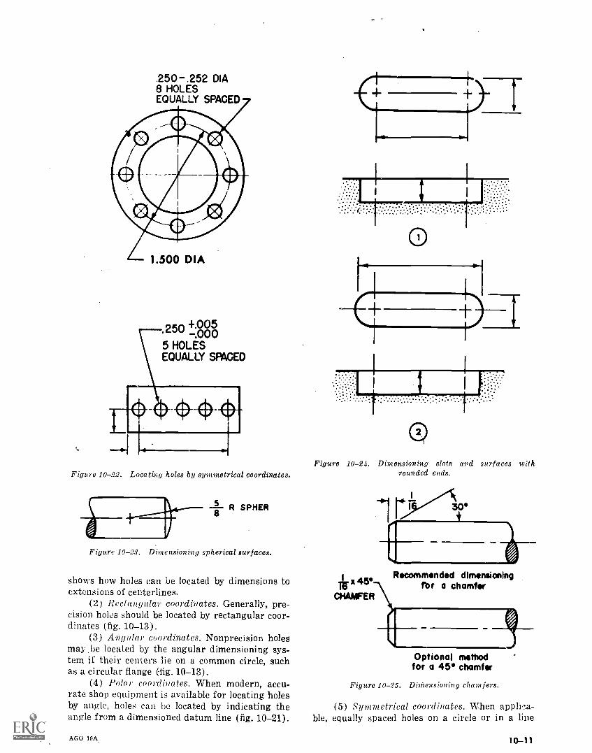
.250-.252 DIA8 HOLESEQUALLY SPACED
1.500 DIA
.250 .04 0500-.05 HOLESEQUALLY SPACED
Figure 10-22. Locating holes by symmetrical coordinates.
R SPHER8
Figure 10-23. Dimensioning spherical surfaces.
shows how holes can be located by dimensions toextensions of centerlines.
(2) Rectangular coordinates. Generally, pre-cision holes should be located by rectangular coor-dinates (fig. 10-13).
(3) Angular coordinates. Nonprecision holesmay .be located by the angular dimensioning sys-tem if their centers lie on a common circle, suchas a circular flange (fig. 10-13).
(4) Polai coordiirates. When modern, accu-rate shop equipment is available for locating holesby angle, holes can be located by indicating theangle from a dimensioned datum line (fig. 10-21).
AGO 19A.
Figure 10-24. Dimensioning slots and surfaces withrounded ends.
45CHAMFER
30
Recommended dimensioningfbr a chamfer
Optional methodfor a 45 chamfer
Figure 10-25. DiMensioning chamfers.
(5) Symmetrical coordinates. When applica-ble, equally spaced holes on a circle or in a line
10-11
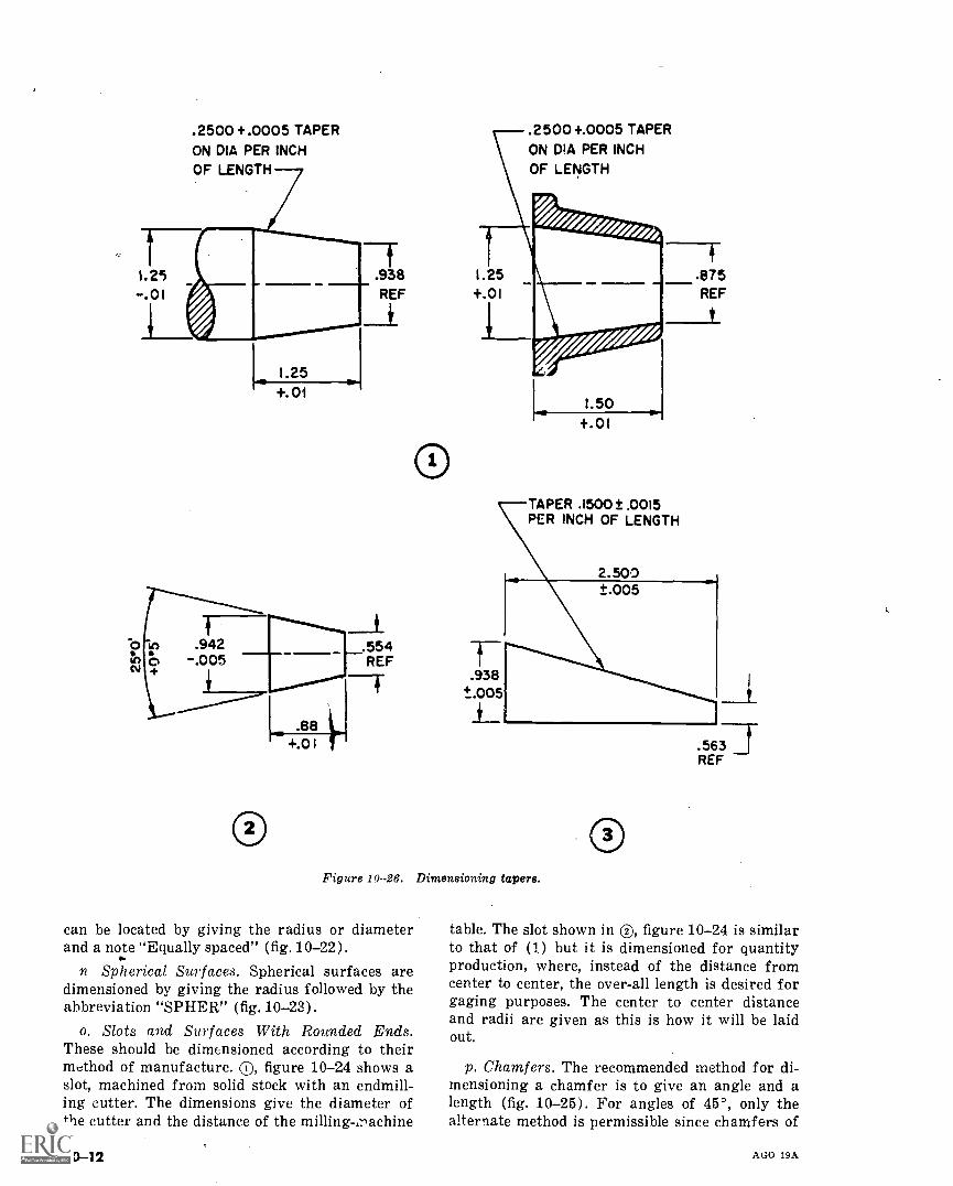
.2500 +.0005 TAPERON DIA PER INCH
OF LENGTH
1.25.01
00
1.25+.01
.938REF
.942 .554.005 REF
O
.88+.0
.2500 +.0005 TAPERON DIA PER INCHOF LENGTH
1.25+.01
TAPER .1500 ± .0015PER INCH OF LENGTH
Figure 10-26. Dimensioning tapers.
can be located by giving the radius or diameterand a note "Equally spaced" (fig. 10-22).
n. Spherical Surfaces. Spherical surfaces aredimensioned by giving the radius followed by theabbreviation "SPHER" (fig. 10-23).
o. Slots and Surfaces With Rounded Ends.These should be dimensioned according to theirmethod of manufacture. (D, figure 10-24 shows aslot, machined from solid stock with an endmill-ing cutter. The dimensions give the diameter ofthe cutter and the distance of the milling,-nachine
10-12
table. The slot shown in (D, figure 10-24 is similarto that of (1) but it is dimensioned for quantityproduction, where, instead of the distance fromcenter to center, the over-all length is desired forgaging purposes. The center to center distanceand radii are given as this is how it will be laidout.
p. Chamfers. The recommended method for di-mensioning a chamfer is to give an angle and alength (fig. 10-25). For angles of 45°, only thealternate method is permissible since chamfers of
AGO 19A
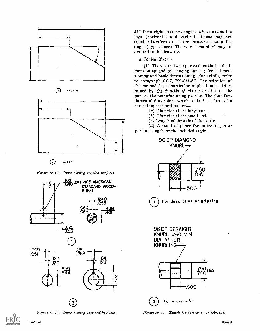
L0 Angular
C) Linear
Figure 10-27. Dimensioning angular surfaces.
DIA ( 405 AMERICANSTANDARD WOOD-RUFF)
.249
.251
0Figure 10-28. Dimensioning keys and keyways.
AGO 19A
45° form right isosceles angles, which means thelegs (horizontal and vertical dimensions) areequal. Chamfers are never measured along theangle (hypotenuse). The word "chamfer" may beomitted in the drawing.
q. Conical Tapers.
(1) There are two approved methods of di-mensioning and tolerancing tapers ; form dimen-sioning and basic dimensioning. For details, referto paragraph 6.6.7, Mil-Std-8C. The selection ofthe method for a particular application is deter-mined by the functional characteristics of thepart or the manufacturing process. The four fun-damental dimensions which control the form of aconical tapered section are
(a) Diameter at the large end.(b) Diameter at the small end.(c) Length of the axis of the taper.(d) Amount of paper for entire length or
per unit length, or the included angle.
96 DP DIAMONDKNURL
.750DIA
.500
For decoration or gripping
96 DP STRAIGHTKNURL .760 MINDIA AFTERKNURLING
750.748
DIA
.500
0 2. For a press-fit
Figure 10-29. Knurls for decoration or gripping.
10-13
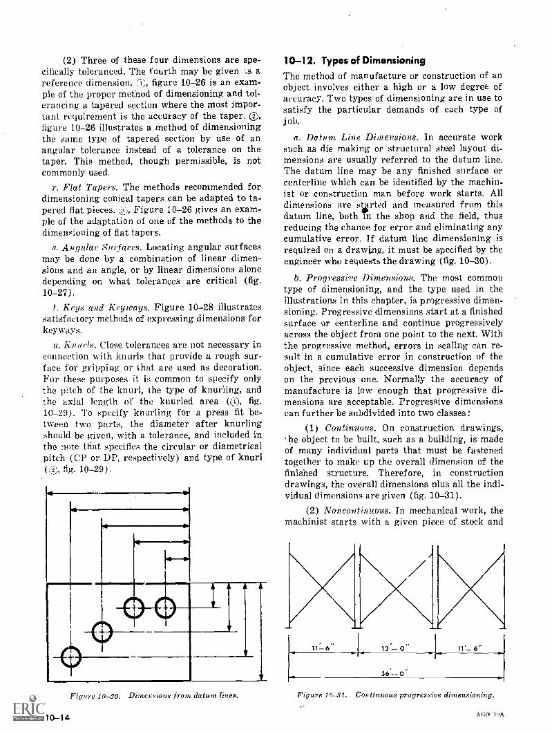
(2) Three of these four dimensions are spe-cifically toleranced. The fourth may be given areference dimension. ;i:;, figure 10-26 is an exam-ple of the proper method of dimensioning and tol-erancing a tapered section where the most impor-tant requirement is the accuracy of the taper. ®,figure 10-26 illustrates a method of dimensioningthe same type of tapered section by use of anangular tolerance instead of a tolerance on thetaper. This method, though permissible, is notcommonly used.
r. Flat Tapers. The methods recommended fordimensioning conical tapers can be adapted to ta-pered flat pieces. Figure 10-26 gives an exam-ple of the adaptation of one of the methods to thedimensioning of Hat tapers.
s. Angular Surfaces. Locating angular surfacesmay be done by a combination of linear dimen-sions and an angle, or by linear dimensions alonedepending on what tolerances are critical (fig.10-27).
t. Keys and Keyways. Figure 10-28 illustratessatisfactory methods of expressing dimensions forkeyways.
u, Knurls. Close tolerances are not necessary inconnection with knurls that provide a rough sur-face for gripping or that are used as decoration.For these purposes it is common to specify onlythe pitch of the knurl, the type of knurling, andthe axial length of the knurled area (0), fig.10-29). To specify knurling for a press fit be-tween two parts, the diameter after knurlingshould be given, with a tolerance, and included inthe note that specifies the circular or diametricalpitch (CP or DP, respectively) and type of knurl(4), fig. 10-29).
Figure 10-30. Dimensions from datum lines.
10-14
1 0-1 2. Types of Dimensioning
The method of manufacture or construction of anobject involves either a high or a low degree ofaccuracy. Two types of dimensioning are in use tosatisfy the particular demands of each type ofjob.
a. Datum Line Dimensions. In accurate worksuch as die making or structural steel layout di-mensions are usually referred to the datum line.The datum line may be any finished surface orcenterline which can be identified by the machin-ist or construction man before work starts. Alldimensions are started and measured from thisdatum line, both in the shop and the field, thusreducing the chance for error and eliminating anycumulative error. If datum line dimensioning isrequired on a drawing, it must be specified by theengineer who requests the drawing (fig. 10-30).
b. Progressive Dimensions. The most commontype of dimensioning, and the type used in theillustrations in this chapter, is progressive dimen-sioning. Progressive dimensions start at a finishedsurface or centerline and continue progressivelyacross the object from one point to the next. Withthe progressive method, errors in scaling can re-sult in a cumulative error in construction of theobject, since each successive dimension dependson the previous one. Normally the accuracy ofmanufacture is low enough that progressive di-mensions are acceptable. Progressive dimensionscan further be subdivided into two classes:
(1) Continuous. On construction drawings,the object to be built, such as a building, is madeof many individual parts that must be fastenedtogether to make up the overall dimension of thefinished structure. Therefore, in constructiondrawings, the overall dimensions nlus all the indi-vidual dimensions are given (fig. 10-31).
(2) Noncontinuous. In mechanical work, themachinist starts with a given piece of stock and
11- 6 13 -0 11 6"
36 -0'
Figure 10-31. Continuous progressive dimensioning.
AGO HA
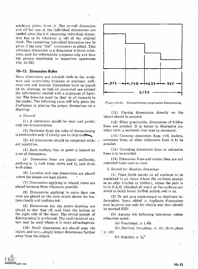
machines pieces from it. The overall dimensionand all but one of the individual dimensions areneeded since the Irst remaining individual dimen-sion has to be whatever is left of the originalstock. The remaining individual dimension can begiven if the note "Ref" (reference) is added. Thisreference dimension is a dimension without toler-ance, used for information purposes only and doesnot govern machining or inspection operations(fig. 10-32).
10-13. Dimension Rules
Since dimensions are valuable both to the work-man and supervising foreman or engineer, suffi-cient size and location dimensions must be placedon the drawing, so that all concerned can extractthe information needed with a minimum of figur-ing. The drawing must be clear in all respects tothe reader. The following rules will help guide thedraftsman in placing the proper dimensions on adraWing:
a. General
(1) A dimension should be clear and permitonly one interpretation.
(2) Deviation from the rules of dimensioningis permissible only if clarity can be improve
(3) All dimensions should be completed without repetition.
(4) Each surface, line, or point is located bya set of: dimensions.
(5 Dimension lines are placed uniformly,preferaLiy IA inch from views and 3/8 inch fromeach other.
(6) Location and size dimensions are placedwhere the shapes are best shown.
(7) Dimensions applying to related views areplaced between them whenever possible.
(8) Dimensions applying to more than oneview are placed on the view which shows the fea-ture clearly and undistorted.
(9) Dimensions for the entire drawing areplaced so tha'-, they all read from the bottom orthe right side of the sheet. The alined system ofdimensioning is preferred. The unidirectional sys-tem may be used where it is more advantageous.
(10) Small dimensions are placed near theobject, and increasingly larger dimensions fartheraway from the object.
AGO 13A
.875 75O .625
3.125
REF
Figure 10-82. Noncontinuous progressive dimensioning.
(11) Placing dimensions directly on theobject should be avoided.
(12) When practicable, dimensions of hiddenlines are avoided. It is better to dimension an-other view ; a sectional view may be necessary.
(13) Crossing dimension lines with leaders,extension lines, or other dimension lines is to beavoided.
(14) Crowding dimension lines or extensionlines is to be avoided.
(15) Dimension lines and center lines are notextended from view to view.
b. Special for Machine Drawings.
(1) Place finish marks on all surfaces to bemachined in all views where the surfaces appearas an edge (visible or hidden), unless the part isto be F.A.O. (finished all over) or the surfaces arenoted as being bored, drilled, milled, and on.
(2) Do not give unnecessary or duplicate in-formation. Some added 3r duplicate dimensionsmay be given but only for clarity and then shouldbe marked REF.
(3) Assume the following tolerances unlessotherwise noted :
(a) Fractional, ± 1/64(b) Decimal, two-place, ± .01; three. place
.001
(c) Angular, ± 1/2°
10-15
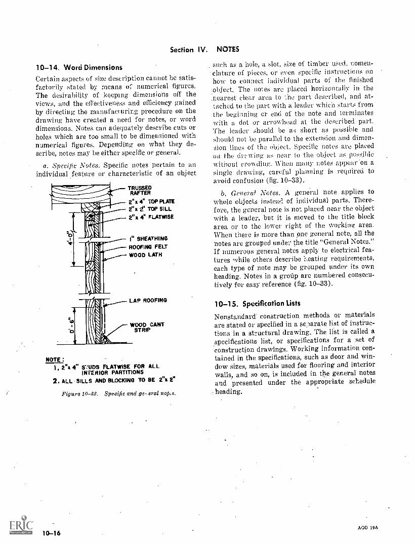
Section IV.
10-14. Word DimensionsCertain aspects of size description cannot be satis-factorily stated by means of numerical figures.The desirability of keeping dimensions off theviews, and the effectiveness and efficiency gainedby directing the manufacturing procedure on thedrawing have created a need for notes, or worddimensions. Notes can adequately describe cuts orholes which are too small to be dimensioned withnumerical figures. Depending on what they de-scribe, notes may be either specific or general.
a. Specific Notes. Specific notes pertain to anindividual feature or characteristic of an object
NOTE
TRUSSEDRAFTER
2" x 4" 'MP PLATE2" x t TOP SILL2"x 4' FLATWISE
I" SHEATHINGROOFING FELT
WOOD LATH
LAP ROOFING
WOOD CANTSTRIP
1, 2"x 4" mos FLATWISE FOR ALLINTERIOR PARTITIONS
2. ALL SILLS AND BLOCKING TO BE 2"x 211
Figure 10-38. Specific and ge,erai
10-16
NOTES
such as a hole, a slot, size of timber used, nomen-clature of pieces, or even specific instructions onhow to connect individual parts of the finishedobject. The notes are placed horizontally in thenearest clear area to the part described, and at-tached to the part with a leader which starts fromthe beginning or end of the note and terminateswith a dot or arrowhead at the described part.The leader should be as short as possible andshould not be parallel to the extension and dimen-sion lines of the object. Specific notes are placedon the (Iry wing as near to the object as possiblewithout crowding. When many notes appear .011 asingle drawing, careful planning is required toavoid confusion (fig. 10-33).
b. General Notes. A general note applies towhole objects instead of individual parts. There-fore, the general note is not placed near the objectwith a leader, but it is moved to the title blockarea or to the lower right of the working area.When there is more than one general note, all thenotes are grouped under the title "General Notes."If numerous general notes apply to electrical fea-tures while others describe L.eating requirements,each type of note may be grouped under its ownheading. Notes in a group are numbered consecu-tively for easy reference (fig. 10-33).
10-15. Specification Lists
Nonstandard construction methods or materialsare stated or specified in a se,larate list of instruc-tions in a structural drawing. The list is called aspecifications list, or specifications for a set ofconstruction drawings. Working information con-tained in the specifications, such as door and win-dow sizes, materials used for flooring and interiorwalls, and so on, is included in the general notesand presented under the appropriate scheduleheading.
AGO 19A
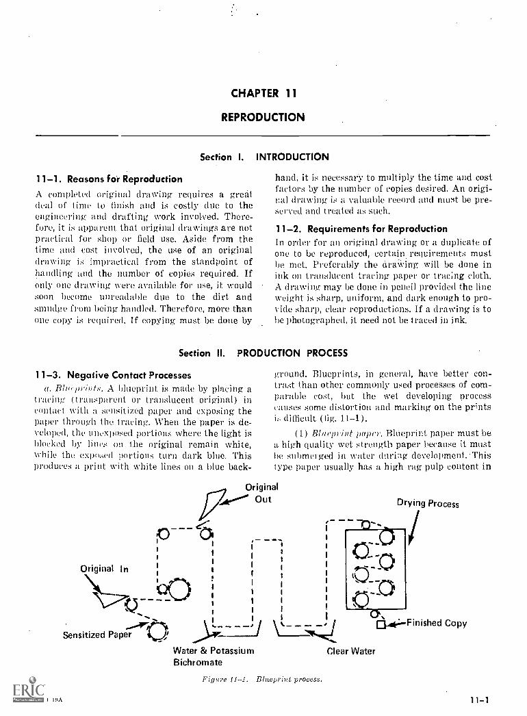
CHAPTER 11
REPRODUCTION
Section I. INTRODUCTION
11-1. Reasons for Reproduction
A completed original drawing requires a greatdeal of time to finish and is costly due to theengineering and drafting work involved. There-fore, it is apparent that original drawings are notpractical for shop or field use. Aside from thetime and cost involved, the use of an originaldrawing is impractical from the standpoint ofhandling and the number of copies required. Ifonly one drawing were available for use, it wouldsoon become unreadable due to the dirt andsmudge from being handled. Therefore, more thanone copy is required. If copying must be done by
hand, it k necessary to multiply the time and costfactors by the number of copies desired. An origi-nal drawing is a valuable record and must be pre-served and treated as such.
11-2. Requirements for ReproductionIn order for an original drawing or a duplicate ofone to be reproduced, certain requirements mustbe met. Preferably the draWing will be done inink on translucent tracing paper or tracing cloth.A drawing may be done in pencil provided the lineweight is sharp, uniform, and dark enough to pro-vide sharp, clear reproductions. If a drawing is tobe photographed, it need not be traced in ink.
Section II. PRODUCTION PROCESS
11-3. Negative Contact Processesa. Blarywints. A blueprint is made by placing a
tracing (transparent or translucent original) incontact with a sensitized paper and exposing thepaper through the tracing. When the paper is de-veloped, the unexposed portions where the light isblocked by lines on the original remain white,while the exposed portions turn dark blue. Thisproduces a print with white lines on a blue back-
Original In
Sensitized Paper,ArOt
A(M 19A
ground. Blueprints, in general, have better con-trast than other commonly used processes of com-parable cost, but the wet developing processcauses some distortion and marking on the printsk, difficult (fig. 11-1).
(1) Bliwprint paper. Blueprint paper must bea high quality wet strength paper because it mustbe submerged in water during development. Thistype paper usually has a high rag pulp content in
OriginalOut
Water & PotassiumBichromate
Figure 11--1. Blueprint process.
11. .13".
Drying Process
Clear Water
0.41,...Finished Copy
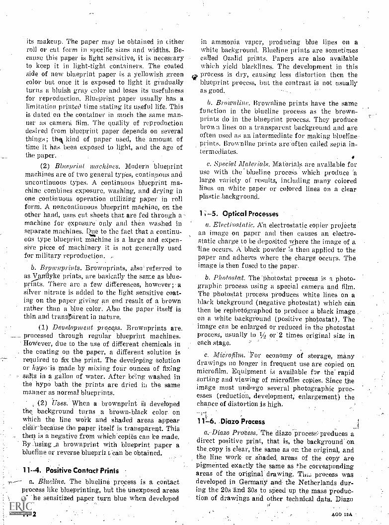
its makeup. The paper may be obtained in titherroll or cut form in specific sizes and widths. Be-cause this paper is light sensitive, it is necessaryto keep it in light-tight containers. The coatedside of new blueprint paper is a yellowish greencolor but once it is exposed to light it graduallyturns a bluish gray color and loses its usefulnessfor reproduction. Blueprint paper usually has alimitation printed time stating its useful life. Thisis dated on the container in much the same man-ner as camera film. The quality of reproductiondesired from blueprint paper depends on severalthings; the kind of paper used, the amount oftime it has been exposed to light, and the age ofthe paper.
(2) Blueprint machines. Modern blueprintmachines are of two general types, continuous anduncontinuous types. A continuous blueprint ma-chine combines .exposure, washing, and drying inone continuous opOration utilizing paper in rollform. A noncontinuous blueprint machine, on theother hand, uses cut sheetS that are fed through amachine for exposure only and then washed inseparate machines. Due to the fact that a continu-ous type blueprint machine is a large and expen-sive piece of machinery it is not generally usedfor military reproduction.
b. Brownprints. Brownprints, also referred toas Van'dyke prints, are basically the same as blue-prints. There are a few differences, however ; asilver nitrate is added to the light sensitive coat-ing on the paper giving an end result of a brownrather than a blue color. Also the paper itself isthin and transparent in nature.
(1) Development proce,ss. Brownprints are.processed through regular blueprint machines.However, due to the use of different chemicals in
. the coating on the paper, a different solution isrequired to fix the print. The developing solutionor hypo is made by mixing four ounces of fixingsalts in a gallon of water. After being washed inthe hypo bath the prints are dried hi the samemanner as normal blueprints.
(2) Uses. When a brownprint is developedthe background turns a brown-black color onwhich the line work and shaded areas appearcle-dar-becaiise the paper itself is transparent. Thisthen is a negative from which:copies can be made.By using _a brownprint with blueprint paper ablueline or reverse blueprii t.can be obtained.
11--4. Positive Contact Prinis
a. Blueline. The blueline process is a contactprocess like blueprinting, but the unexposed areasof the sensitized paper turn blue when developed
11 -2
in ammonia vapor, producing blue lines on awhite background. Blueline prints are sometimescalled Ozalid prints. Papers are also availablewhich yield blacklines. The development in thisprocess is dry, causing less distortion then theblueprint process, but the contrast is not usuallyas good.
b. &minable; Brownline prints have the samefunction in the blueline process as the brown-prints do in the blueprint process. They producebrown lines on a transparent background and areoften used as an intermediate for making bluelineprints. Brownline prints are often called sepia in-termediates.
4c. Special Materials. Materials are available for
use with the blueline proceSs which produce 'alarge variety of results, including many coloredlines on white paper or colored lines on a clearplastic background.
1 5. Optical Processes .
a. Electiostatic. An electrostatic copier projectsan image on paper and then causes an electro-static charge.to be deposited where the image of aline occurs. A. black powder is then applied to thepaper and adheres where the charge occurs. Theimage is then fused to the paper.
b. Photostat. The-Photostat process is a photo-graphic process using a special camera and film.The photostat process produces white lines on ablack background (negative photostat) which canthen be rephotdgraphed to produce a black imageon a white background (positive photostat). Theimage can be enlarged or reduced in the photostatprocess, usually to 1A or 2 times original size ineach stage.
c. Microfilm. 1or economy of storage, many.drawings no longer in frequent use are copied onmicrofilm. Equipment is available for the rapidsorting and viewing of microfilm copies. Since theimage must undergo -several photographic proc-esses (reduction, development; enlargement) theChance of distortion.iS high.
1 Diazo Process
a.Diazo Process. The diazo-Procese.:-produces adirect positive print, that is, the background- onthe copy is clear, the same as on the original, andthe line work or shaded areas of the copy arepigmented exactly the same as the correspondingareas of the original, drawing. process wasdeveloped in GermanY and the Netherlands dur-ing the 20s and 30s to speed up the mass produo-ton. of drawings and other technical data. Diazo
AGO 19A
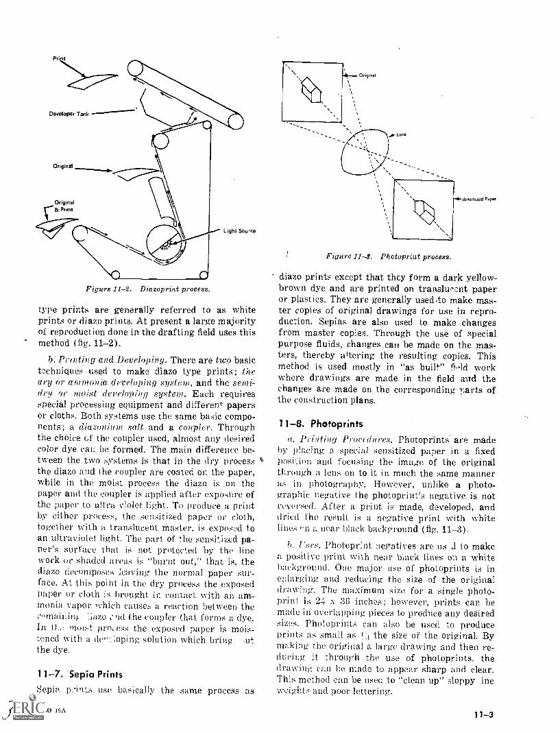
Pri
Developer Tank
Original
Originalc& Print
Figure 11-2. Diazoprint process.
Light Source
type prints are generally referred to as whiteprints or diazo prints. At present a large majorityof reproduction done in the drafting field uses thismethod (fig. 11-2).
b. Printing and Developing. There are two basictechniques used to make diazo type prints; theary or ammonia, developing system., and the semi-dry or moist developing system. Each requiresspecial processing equipment and different papersor cloths. Both systems use the same basic compo-nents; a diazonium salt and a coupler. Throughthe choice of the coupler used, almost any desiredcolor dye car. be formed. The main difference be-tween the two systems is that in the dry processthe diazo and the coupler are coated on the paper,while in the moist process the diazo is on thepaper and the coupler is applied after exposure ofthe paper to ultra violet light. To produce a printby either process, the sensitized paper or cloth,together with a translucent master, is exposed toan ultraviolet light. The part of the sensitized pa-per's surface that is not protected by the linework or shaded areas is "burnt out," that is, thediazo decomposes eaving, the normal paper sur-face. At this point in the dry process the exposedpaper or cloth is brought in contact with an am-monia vapor which causes a reaction between thec' maillint ;iazo ,:nd the coupler that forms a dye.In tt., moist process the exposed paper is mois-tened with a de-:loping solution which bring ,utthe dye.
11 -7. Sepia Prints
Sepia p...ints use basically the same process as
AGO 19A
Figure 11-3. Photoprint process.
Sensitized Pdper
diazo prints except that they form a dark yellow-brown dye and are printed on translucent paperor plastics. They are generally usedto make mas-ter copies of original drawings for use in repro-duction. Sepias are also used to make changesfrom master copies. Through the use of specialpurpose fluids, changes can be made on the mas-ters, thereby altering the resulting copies. Thismethod is used mostly in "as built" fold workwhere drawings are made in the field avtd thechanges are made on the corresponding parts ofthe construction plans.
11 -8. Photoprints
a. Printing Procedures. Photoprints are madeby placing a special sensitized paper in a fixedposition and focusing the image of the originalthrough a lens on to it in much the same manneras in photography. However, unlike a photo-graphic negative the photoprint's negative is notreversed. After a print is made, developed, anddried the result is a negative print with whitelines on a near black background (fig. 11-3).
b. Uses. Photoprint negatives are us 1 to makea positive print with near black lines on a whitebackground. One major use of photoprints is inenlarging and reducing the size of the originaldrawing. The maximum size for a single photo-print is 24 x 36 inches; however, prints can bemade in overlapping pieces to produce any desiredsizes. Photoprints can also be used to produceprints as small as 1."3 the size of the original. Bymaking the original a large drawing and then re-ducing it through the use of photoprints, thedrawing can be made to appear sharp and clear.This method can be used to "clean up" sloppy -lineweights and poor lettering.
11 -3
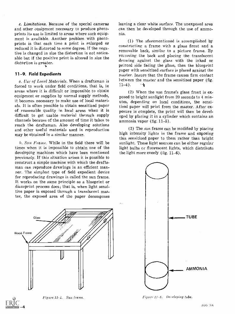
c. Limitations. Because of the special camerasand other equipment necessary to produce photo-prints its use is limited to areas where such equip-ment is available. Another problem with photo-prints is that each time a print is enlarged orreduced it is distorted to some degree. If the nega-tive is changed in size the distortion is not notice-able but if the positive print is altered in size thedistortion is greater.
1 1-9. Field Expedients
a. Use of Local Materials. When a draftsman isforced to work under field conditions, that is, inareas where it is difficult or impossible to obtainequipment or supplies by normal supply methods,it becomes necessary to make use of local materi-als. It is often possible to obtain sensitized paperof reasonable quality in local areas when it isdifficult to get usable material through supplychannels because of the amount of time it takes toreach the draftsman. Also developing solutionsand other useful materials used in reproductionmay be obtained in a similar manner.
b. Sun Frame. While in the field there will betimes when it is impossible to obtain one of thedeveloping machines which have been mentionedpreviously. If this situation arises it is possible toconstruct a simple machine with which the drafts-man can reproduce drawings in an efficient man-ner. The simplest type of field expedient devicefor reproducing drawings is called the sun frame.It works on the same principle as a blueprint ordiazoprint process does; that is, when light sensi-tive paper is exposed through a translucent mas-ter, the exposed area of the paper decomposes
Wood Frame
11-4
Figure 11-4. Sun frame.
leaving a clear white surface. The unexposed areacan then be developed through the use of ammo-nia.
(1) The aforementioned is accomplished byconstructing a frame with a glass front and aremovable back, similar to a picture frame. Byrei.loving the back and placing the translucentdrawing against the glass with the inked orprinted side facing the glass, then the blueprintpaper with sensitized surface is placed against themaster. Insure that the frame causes firm contactbetween the master and the sensitized paper (fig.11-4).
(2) When the sun frame's glass front is ex-posed to bright sunlight from 20 seconds to 4 min-utes, depending on local conditions, the sensi-tized paper will print from the master. After ex-posure is complete, the print will then be devel-oped by placing it in a cylinder which contains anammonia vapor (fig. 11-5).
(3) The sun frame can be modified by placinghigh intensity lights in the frame and exposingthis sensitized paper to them rather than brightsunlight. These light sources can be either regularlight bulbs or fluorescent lights, which distributethe light more evenly (fig. 11-6).
Figure 11-5. Developing tube.
AGO I9A
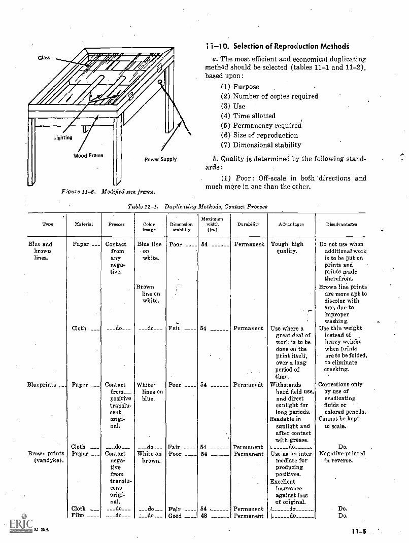
Glass
"r4feZaTee
Lighting
Wood FramePower Supply
Figure 11-6. Mod' fied sun frame.
1 -10. Selection of Reproduction Methodi
a. The most efficient and economical duplicatingmethod should be selected (tables 11-1 and 11-2),based upon :
(1) Purpose(2) Number of copies required(3) Use(4) Time allotted(5) Permanency required(6) Size of reproduction(7) Dimensional stability
b. Quality is determined by the following stand-ards:
(1) Poor: Off-scale in both directions andmuch more in one than the other.
Table 11-1. Duplicating Methods, Contact Process
Type Material Process Colorimage
Dimensionstability
Maximumwidth(in.)
Durability Advantages Disadvantages
Blue andbrownlines.
Paper ___ Contactfromanynega-tive.
Blue lineonwhite.
i Poor ____ 54 Permaneni, Tough, highquality.
Do not use whenadditional worthis to be put onprints andprints madetherefrOm.
Brown Brown line print:line onwhite.
_
are more apt tcdiscolor withage, due
washing.Cloth ___ __do_ __ ___do___ Fair ____ 54 Permanent Use where a
great deal ofwork is to bedone on theprint itself,over a longperiod oftime.
Use thin weightinstead ofheavy weightwhen printsare to be foldedto eliminatecracking.
Blueprints __ Paper __ _ Contactfrom_positivetranslu-centorigi-nal.
Whitelines onblue.
Poor ____ 54 Permanent Withstandshard field use,and directsunlight forlong periods.
Readable insunlight andafter contactwith grease.
Corrections onlyby use oferadicatingfluids orcolored pencils.
Cannot be keptto scale.
Cloth ___ __do ___ ___do ___ Fair ____ 54 Permanent \.. do Do.Brown prints Paper ___ Contact White on Poor ____ 54 Permanent Use as an inter- Negative printed
(vandyke). nega-tivefromtranslu-centorigi-nal.
brown. mediate forproducingpositives.
Excellentinsuranceagainst lossof original.
in reverse.
Cloth ___ ___do___ ___do___ Fair ____ 54 Permanent i do_ Do.Film ____ ___do__ __do ___ Good ____ 48 Permanent ( do Do.
AGO 19A 11 -5 .
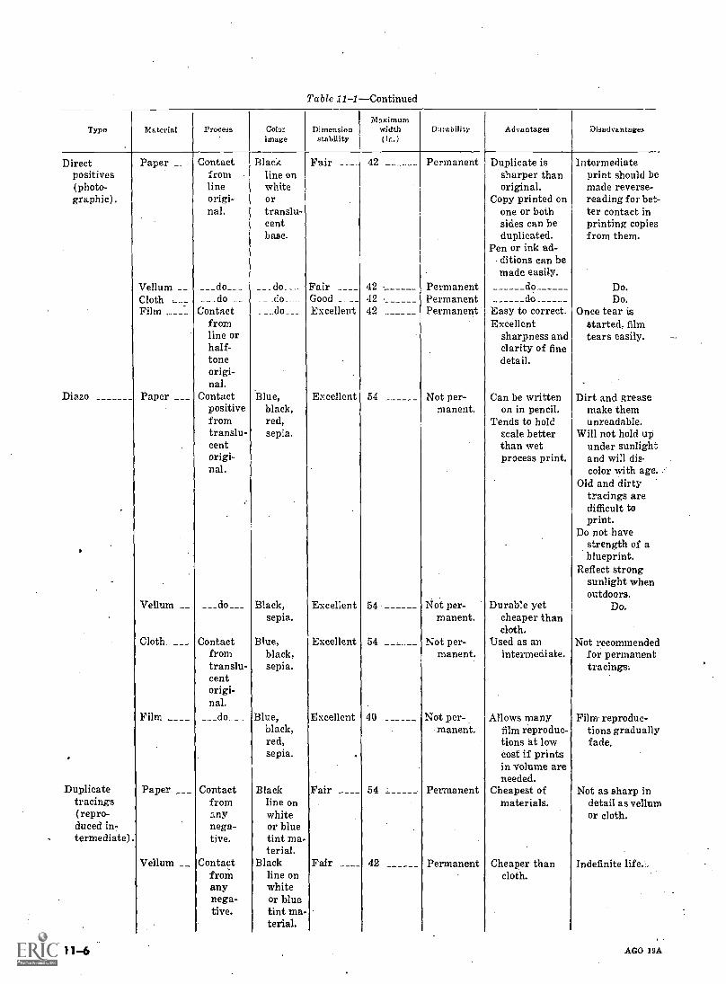
Table 11IContinued
Type Material Process Colorimage
Dimensionstability
Maximumwidth(in.)
Durability Advantages Disadvantages
Direct Paper _ _ Contact Black Fair __ _ 42 Permanent Duplicate is Intermediatepositives from line on sharper than print should be(photo- line white original. made reverse-graphic). origi-
nal.ortranslu-centbase.
Copy printed onone or bothsides can beduplicated.
reading for bet-ter contact inprinting copiesfrom them.
Pen or ink ad-. ditions can bemade easily.
Vellum __ ___do___ __do_ __ Fair ____ 42 Permanent do Do.Cloth ,__.7 . _ _do _ _ _ do. _ Good __ 42 . Permanent do Do,Film ,____ Contact
fromline orhalf-
___ do __ Excellent 42 Permanent Easy to correct.Excellent
sharpness andclarity of fine
Once tear isstarted, filmtears easily.
toneorigi-nal.
.
detail.
Diazo Paper Contactpositivefromtranslu-centorigi.nal.
Blue,black,red,sepia.
Excellent 54 Not per-manent.
Can be writtenon in pencil.
Tends to holdscale betterthan wetprocess print,
Dirt and greasemake themunreadable.
Will not hold upunder sunlightand will dis.color with age.
Old and dirtytracings aredifficult toprint.
Do not havestrength of ablueprint.
Reflect strongsunlight whenoutdoors.
Vellum __ ___ do___ Black,sepia.
Excellent 54 Not per-manent.
Durable yetcheaper thancloth.
Do.
Cloth. ___ Contactfromtranslu-cent
Blue,black,sepia.
Excellent 54 Not per-manent.
Used as anintermediate.
Not recommendedfor permanenttracings.
origi-nal.
Film ____ ___do___ Blue,black,red,sepia.
Excellent
.
40 Not per-manent.
Allows manyfilm reproduc-tions at lowcost if printsin volume areneeded.
Film reproduc-tions graduallyfade.
Duplicate Paper ___ Contact Black Fair ____ 54 : Permanent Cheapest of Not as sharp intracings(repro -
fromany
line onwhite
materials. detail as vellunor cloth.
duced in-termediate).
nega-tive.
or bluetint ma-terial.
.
Vellum __ Contactfromanynega-tive.
Blackline onwhiteor bluetint ma-terial.
Fair ____ 42 Permanent Cheaper thancloth.
Indefinite life.:,
11-6 AGO 19A
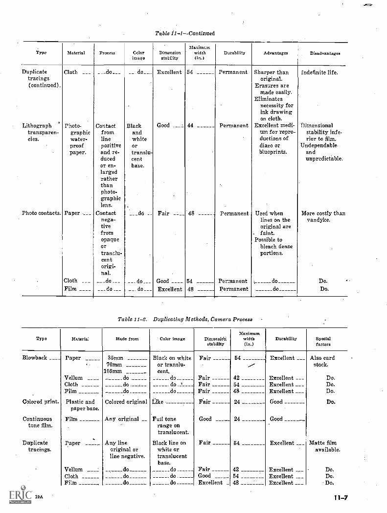
Table 11-1Continued
Type Material Process Colorimage
Dimensionstability
Maximumwidth(in.)
Durability Advantages Disadvantages
Duplicatetracings
Cloth ___ ___do___ __ do___ Excellent 54 Permanent Sharper thanoriginal.
Indefinite life.
(continued). Erasures aremade easily.
Eliminatesnecessity forink drawingon cloth.
Lithograph Photo- Contact Black Good ___ 1 44 Permanent Excellent medi- Dimensionaltransparen- graphic from and urn for repro- stability infe-cies. water- line white ductions of rior to film.
proof positive or diazo or Undependablepaper. and re-
ducedor en-largedratherthan
translu-centbase.
blueprints. andunpredictable.
photo-graphiclens.
Photo contacts. Paper __ _ Contactnega-tivefromopaqueortranslu-cent
___do Fair ____ 48 Permanent Used whenlines on theoriginal are
. faint.Possible to
bleach denseportions.
More costly thanvandyke.
origi-nal.
Cloth ___ __do__ __. do___ Good ____ 54 Permanent do Do.
Film ____ ___do _ __. do___ Excellent 48 Permanent do Do.
Table 11-2. Duplicating Methods, Camera Process
Type Material Made from Color image Dimensithistability
Maximumwidth(in.)
Durability Specialfactors
Blowback ____ Paper 35mm Black on white Fair 54 Excellent ___ Also card70mm
105mmor translu-cent.
...--- stock.
Vellum ____ _do. do_ Fair 42 Excellent ___ Do.Cloth do . do _ t' Fair 54 Excellent ___ Do.Film do_ do_ Fair 48 Excellent ___ Do.
.
Colored print. Plastic andpaper base.
Colored original Like Fair 24 Good Do.
Continuous Film Any original Full tone Good 24 Goodtone film. range on
translucent.. -
Duplicatetracings.
Paper Any lineoriginal orline negative.
Black line onwhite ortranslucentbase.
Fair 54 Excellent ___ Matte filmavailable.
Vellum _ _ do do _ Fair 42 Excellent ___ Do.Cloth do do Good 54 Excellent ___ Do.Film do do Excellent 48 Excellent ___ Do.
AGO 19A 11 -7
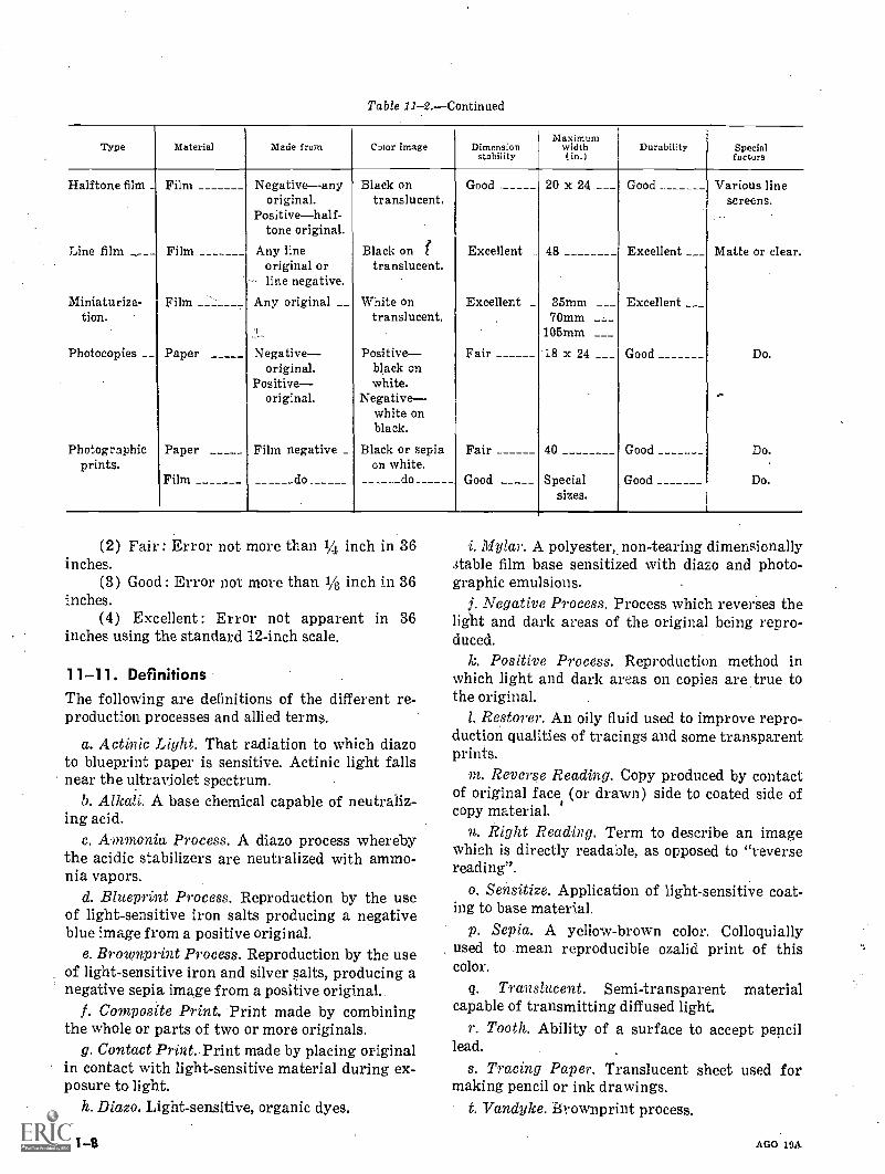
Table 11-2.---Continued
Type Material Made from Color image Dimensionstability
Maximumwidth(in.)
Durability Specialfactors
Halftone film _ Film Negative--anyoriginal.
Black ontranslucent.
Good 20 x 24 ___ Good Various linescreens.
Positivehalf-tone original.
Line film ____ Film Any lineoriginal or
Black on rtranslucent.
Excellent 48 Excellent ___ Matte or clear.
line negative.
Miniaturiza-tion.
Film Any original __ White ontranslucent.
Excellent _ 35mm ___70mm ___
Excellent __
105mm ___
Photocopies __ Paper Negativeoriginal.
Positiveoriginal.
Positiveblack onwhite.
Negativewhite onblack.
Fair, 18 x 24 ___ Good Do.
..-
Photographicprints.
Paper Film negative _ Black or sepiaon white.
Fair 40 Good Do.
Film do do Good Specialsizes.
Good Do.
(2) Fair : Error not more than 1/4 inch in 36inches.
(3) Good : Error not more than 1/8 inch in 36inches.
(4) Excellent : Error not apparent in 36inches using the standard 12-inch scale.
1 1-11. DefinitionsThe following are definitions of the different re-production processes and allied terms.
a. Actinic Light. That radiation to which diazoto blueprint paper is sensitive. Actinic light fallsnear the ultraviolet spectrum.
b. Alkali. A base chemical capable of neutraliz-ing acid.
c. Ammonia Process. A diazo process wherebythe acidic stabilizers are neutralized with ammo-nia vapors.
d. Blueprint Process. Reproduction by the useof light-sensitive iron salts producing a negativeblue image from a positive original.
e. Brownprint Process. Reproduction by the useof light-sensitive iron and silver salts, producing anegative sepia image from a positive original.
f. Composite Print. Print made by combiningthe whole or parts of two or more originals.
g. Contact Print. Print made by placing originalin contact with light-sensitive material during ex-posure to light.
h. Diazo. Light-sensitive, organic dyes.
11 -8
i. Mylar. A polyester non-tearing dimensionallystable film base sensitized with diazo and photo-graphic emulsions.
j. Negative Process. Process which reverses thelight and dark areas of the original being repro-duced.
Positive Process. Reproduction method inwhich light and dark areas on copies are true tothe original.
1. Restorer. An oily fluid used to improve repro-duction qualities of tracings and some transparentprints.
Reverse Reading. Copy produced by contactof original face (or drawn) side to coated side ofcopy material.
n. Right Reading. Term to describe an imagewhich is directly readable, as opposed to "reversereading".
o. Sensitize. Application of light-sensitive coat-ing to base material.
p. Sepia. A yellow-brown color. Colloquiallyused to .mean reproducible ozalid print of thiscolor.
q. Translucent. Semi-transparent materialcapable of transmitting diffused light.
r. Tooth. Ability of a surface to accept pencillead.
s. Tracing Paper. Translucent sheet used formaking pencil or ink drawings.
t. Vandyke. Brownprint process.
AGO 19A
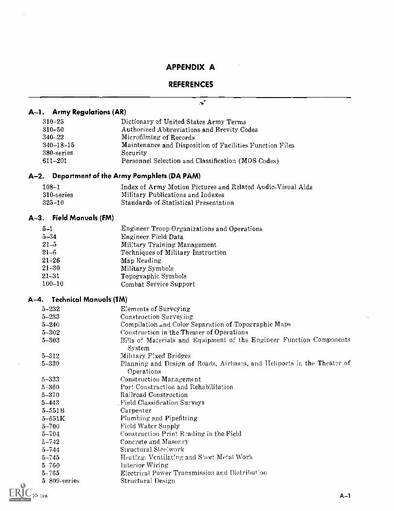
APPENDIX A
REFERENCES
A-1. Army Regulations (AR)310-25 Dictionary of United States Army Terms310-50 Authorized Abbreviations and Brevity Codes340 - -22 Microfilming of Records340-18-15 Maintenance and Disposition of Facilities Function Files380-series Security611-201 Personnel Selection and Classification (MOS Codes)
A-2. Department of the Army Pamphlets (DA PAM)
108-1 Index of Army Motion Pictures and Related Audio-Visual Aids310-series Military Publications and Indexes325-10 Standards of Statistical Presentation
A-3. Field Manuals (FM)
5-1 Engineer Troop Organizations and Operations5-34 Engineer Field Data21-5 Military Training Management21-6 Techniques of Military Instruction21-26 Map Reading21-30 Military Symbols21-31 Topographic Symbols100-10 Combat Service Support
A-4. Technical Manuals (TM)5-232 Elements of Surveying5-233 Construction Surveying5-240 Compilation and Color Separation of Topographic Maps5-302 Construction in the Theater of Operations5-303 Bills of Materials and Equipment of the Engineer Function Components
System5-312 Military Fixed Bridges5-330 Planning and Design of Roads, Airbases, and Heliports in the Theater of
Operations5-333 Construction Management5-360 Port Construction and Rehabilitation5-370 Railroad Construction5-443 :Field Classification Surveys5-551B Carpenter5-551K Plumbing and Pipefitting5-700 Field Water Supply5-704 Construction Print Reading in the Field742 Concrete and Masonry
5-744 Structural Steelwork5-745 Heating. Ventilating and Sheet Metal Work5-760 Interior Wiring5-765 Electrical Power Transmission and Distribution5-809-series Structural Design
AGO 19A A-1
A-5. Corps of Engineer, Military Standards (MILSTU)
8C9A12C14A15-1A15-3
18A100A
A-6. Other Agencies
NAVFAC DM-6EP 415-1-260
through 264JANSTD-19DIADIANAVPERSNAVPERSUSACERC
Tech Rep 4
A-2
Dimensioning and TolerancingScrew Thread Conventions and Methods of SpecifyingAbbreviations for use on Drawings. and in Technical-Type PublicationsArchitectural SymbolsGraphic Symbols for Electrical and Electronic DiagramsElectrical Wiring Symbols for Architectural and Electrical Layout
DrawingsMechanical SymbolsStructural SymbolsEngineer Drawing Piactice
Design Manual, Drawings and Specification (US Navy)Resident Engineers' Management Guide (Corp of Engineers)Welding Symbols (Joint Army-Navy) ,!
Industrial Security Manual 'for Safeguarding Classified (DOD) InformationGlossary of Mapping, Charting and Geodetic TermsAmerican Institute of Steel Construction Manual (AISC)Draftsman 3 and'2Draftsman 1 and CShore Protection, Planning and Design
Design by Elwyn E. See lye, Published by John Wiley and Sons, Inc.
AGO 19A
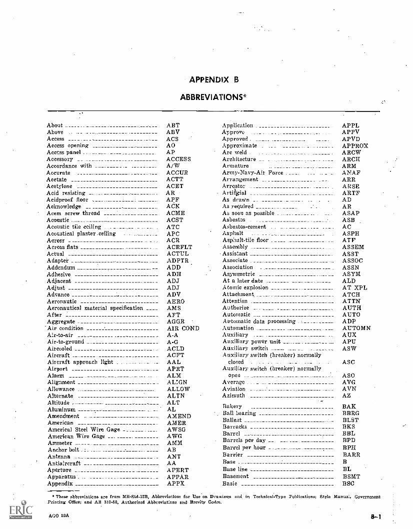
APPENDIX B
ABBREVIATIONS*
About ABT Application APPLAbove ABV Approve _ _ _ APPVAccess ACS Approved ._ .. _ APVDAccess opening AO Approximate _ _ APPROXAccess panel . AP Are weld . _ ARCWAccessory ACCESS Architecture ARCHAccordance with A/W Armature _ ARMAccurate ACCUR Army-Navy-Air Force __ _ _. ANAFAcetate ACTT Arrangement ARRAcetylene ACET Arrestor ARSRAcid resisting AR Artificial ARTFAcidproof floor APF As drawn _ ADAcknowledge ACK As required ARAmyl screw thread ACME As soon as possible ASAPAcoustic ACST Asbestos ASBAcoustic tile ceiling ATC Asbestos-cement . . _. ACAcoustical plaster .ceiling APC Asphalt ASPHAcross ACR Asphalt-tile floor . ____ _____________ ATF .Across flats ACRFLT Assembly ASSEMActual ACTUL Assistant ASSTAdaptei ADPTR Associate ASSOCAddendum ADD Association ASSNAdhesive ADH Asymmetric ASYMAdjacent ADJ At a later date ALDAdjust ADJ Atomic explosion AT XPLAdvance ADV Attachment ATCHAeronautic AERO Attention ATTNAeronautical material specification ____ AMS Authorize AUTHAfter AFT Automatic AUTOAggregate AGGR Automatic data processing ADPAir condition AIR COND Automation AUTOMNAir-to-air A-A Auxiliary AUXAir-to-ground A-G Auxiliary power unit APUAircooled ACLD Auxiliary switch ASWAircraft ACFT Auxiliary switch (breaker) normallyAircraft approach light AAL closed ASCAirport APRT Auxiliary switch (breaker) normallyAlarm ALM open ASOAlignment ALIGN Average AVGAllowance ALLOW Aviation AVNAlternate ALTN Azimuth AZAltitude ALTAluminum AL Bakery BAK
AmendmentAmerican
AMENDAMER
Ball bearingBallast
BBRGBLST
America] Steel Wire. Gage AWSG Barracks BKS
American Wire Gage AWG Barrel BBL
Ammeter AMM Barrels per day BPD
Anchor bolt .:_ _______ ______ _ __ AB Barrel per hour BPHAntenna ANT Barrier BARRAntiaircraft ___ ____ AA Base B
Aperture _______ _ APERT Base line BLApparatus_ APPAR Basement BSMTAppendix APPX Basic BSC
* These abbreviaticns are from Mil-Std-12B, Abbreviations for Use on Drawings and, in Technical-Type Publications; Style Manual, GovernmentPrinting Office; and AR 310 -90, Authorized Abbreviations and Brevity Codes.
AGO 19A B-1
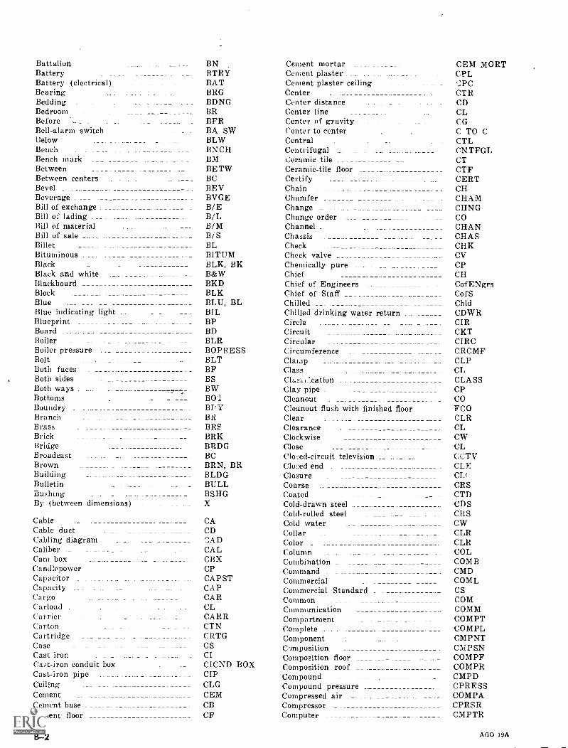
Battalion BN Cement mortar __ CEM MORTBattery BTRY Cement plaster CPLBattery (electrical) BAT Cement plaster ceiling '.',PCBearing BRG Center CTRBedding BDNG Center distance CDBedroom BR Center line __ _ CLBefore . . BFR Center of gravity CGBell-alarm switch BA SW Center to center C TO CBelow BLW Central CTLBench BNCH Centrifugal CNTFGLBench mark BM Ceramic tile CTBetween BETW Ceramic-tile floor CTFBetween centers BC Certify CERTBevel BEV Chain CHBeverage _ BVGE Chamfer CHAMBill of exchange B/E Change CHNGBill of lading B/L Change order COBill of material . B/M Channel CHANBill of sale _ B/S Chassis CHASBillet BL Check CHKBituminous BITUM Check valve CVBlack BLK, BK Chemically pure CPBlack and white _ B&W Chief CHBlackboard BKD Chief of Engineers CofENgrsBlock BLK Chief of Staff CofSBlue BLU, BL Chilled ChldBlue indicating light BI L Chilled drinking water return CDWRBlueprint BP Circle CIRBoard BD Circuit CKTBoiler BLR Circular CIRCBoiler pressure BOPRESS Circumference CRCMFBolt BLT Clamp CLPBoth faces BF Class CLBoth sides BS Ch..szi::cation CLASSBoth ways MY* Clay pipe CPBottoms BO ..1 Cleanout COBoundry BPY Cleanout flush with finished floor FCOBranch BR Clear CLRBrass BRS Clearance CLBrick BRK Clockwise CWBridge BRDG Close CLBroadcast BC Closed- circuit television CCTVBrown _ BRN, BR Closed end CLEBuilding BLDG Closure CL(Bulletin BULL Coarse CRSBushing BSHG Coated CTDBy (between dimensions) X Cold-drawn steel CDS
Cold-rolled steel CRSCable CA Cold water CWCable duct CD Collar CLRCabling diagram CAD Color _ CLRCaliber CAL Column COLCam box CBX Combination _ COMBCandlepower CP Command CMDCapacitor CAPST Commercial COMLCapacity CAP Commercial Standard CSCargo CAR Common COMCarload CL Communication COMMCarrier CARR Compartment COMPTCarton CTN Complete COMPLCartridge CRTG Component CMPNTCase CS Composition CIVIPSNCast iron CI Composition floor COMPFCast-iron conduit box CICND BOX Composition roof COMPRCast-iron pipe ._ _ _ _ CIP Compound CMPDCeiling CLG Compound pressure CPRESSCement CEM Compressed air _ COMPACement base _ CB Compressor CPRSRCement floor CF Computer CMPTR
B-2 AGO 19A
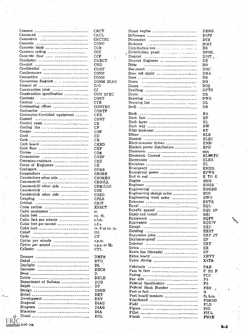
Concave CNCV Diesel engine DENGConcealed CN CL Difference D1FFConcentric CNCTRC Dimension DIMConcrete CONC Distance DISTConcrete block CCB Distribution box DBConcrete ceiling CCC Distribution panel DPNLConcrete floor CCF District DISTConductor CNDCT District Engineer DEConduit CND Ditto DOConfidential CONF Document DOCConformance CONF Does not apply DNAConnection CONN Door DRConnection diagram CONN DIAG Down DNConsist of C/ 0 Dozen DOZConstruction joint CJ Drafting DFTGConstruction specification CON SPEC Drain DRContents CONT Drawing DWGContour CTR Drawing list DLContracting officer CONTRO Drill DRContractor CONTPContractor-furnished equipment CFE Each _ EAControl CONT Each face EFControl room CR Each layer ELCooling fan CF Each way EWCooper COP Edge thickness ETCord CD Elbow ELBCork CK Electric .. ELECCork board CKBD Electric-motor driven EMDCork floor CKF Electric power distribution EPDCorner COR Electronic _ elctCorporation CORP Electronic Control ELEbeTCCorrosion-resistant CRE Electronics ELEXCorps of Engineers CE Elevation ELCorrugate . CORR Emergency EMERCounterbore CBORE Emergency power EPWRCounterbore other side ____ .__..--- CBOREO End to end E TO ECounterdrill CDRILL Engine ENGCounterdrill other side _ _ CDRILLO Engineer ENGRCountersink CSK Engineering ENGRGCountersink other side CSKO Engineering change order ECOCoupling CPLG Engineering work order EWOCritical CRIT Entrance ENTRCross section XSECT Equal EQL--
Cubic centimeter CCEqually spaced EQL SP
Cubic fobt cu. ft. Equip and install E&ICubic feet per minute c.f.m. Equipment EQPTCubic feet per second c.f.s. Equivalent EQUIVCubic inch in. 3 or cu. in. Except __ EXCCutoff CO Existing EXSTCycle CY Expansion joint EXP JTCycles per minute c.p.m. Explosion-proof EPCycles per second c.p.s. or Hz Exterior EXTCylinder CYL Extra EX
Extra fine (threads) EFDamper DMPR Extra heavy XHVYDated DTD Extra strong XSTRDaylight DL Fabricate FABDecreaseDeep
DECR Face to faceFacing
F TO FFCCDelete DELE Far side FSDepartment of Defense DOD Federal Specification FSDepth DP Federal Stock Number FSNDesign DSGN Feet or foot ft
Detail DET Feet board'measure ft. b.m.Development DEV Fiberboard FBRBDDiagonalDiagram
DIAGDIAG
Field _____Figure
FLDFIG
Diameter DIA Fillet FILLDiesel DSL Finish FNSH
AGO 19A
Finish all overFinish one sideFinish specification (number)
FAOF1SFS
GovernmentGovernment-furnished equipmentGovernment-furnished material
GOVTGFEGFM
Finish ,wo sides F2S Government- furnished property _ GFPFire F Grade GRFire alarm box FABX Grade line GLFire door FDR Graduation GRDTNFire extinguisher FEXT Graphic GRPHFire-hose cabinet FHC Graphite GPHFire-hose rack FHR Gravel GVLFire hose hydrant FHY Gray GRA, GYFire re-istant FRES Grease trap GTFireproof FPRF Green GRN, GFitting FTG Green indicating lamp _ GILFlammable FLMB Greenwich mean time GMTFlange FLG Groove GRVFlat head FLH Gross weight GRWTFlexible FLEX Ground GNDFloodlight . FLDT Ground -to -air G-AFloor FL Ground to ground G-GFloor drain FD Guarantee GUARFluorescent _ FLUOR Guard GDFlush FL Guard rail GDRFlush type FLTP Gypsum-plaster ceiling GPCFooting FTGForged steel __ _ FST Hand control ________ HND CONTFoundation FDN Hand rail HNDRL
Four-pole 4P Handbook HDEK
Four-pole switch _ 4P SW Hanger HGR
Four-way 4WAY Hard HD
Four -wire 4W Hard-drawn HD DRNFractional FRAC Hardware HDW
Frame FR Heat resisting HT RESFramework _ FRWK Heavy - - HVYFreezer FRZR Heavy (insui)Fresh water FW Heavy daty HD
From below FR BEL Height _ _ HGT
Front FR Hexagonal head HEX HDFront view FV High
Fuel line FT,N High-carbon steel ___ HCS
Fuel oil FO High frequency HFFuel tank FTK High voltage HV
Full scale FSC High-water line _ HWLFull size r'S Highway HWYFurnish FURN Hinge HNG
Furniture FURN Holder HLOR
Fuse box FUBX Hollow HOLHollow metal LIM
Gage GA Hollow metal door and frame HMDFGallon gal. Ho-fizontal HORIZGalvanize GALV Horizontal center line HCLGalvanized iron GALVI Hose bib HBGalvanized steel GALVS Hose Connector HCONNGas weld _ . GAS/W Hospital HOSPGasket GSKT Hot-rolled stee' HRSGasoline GAS Hot water HWGasoline engine CENG Hot-water circulating HW CGasoline engine driven GED Hot-water heater IIWHGate valve GTV House HSEGearbox GRBX Housing HSGGeneral GENL Hydraulic HYDRGeneral contractor GEN CONT Identifieltion IDENTGeneratorGlass
GENGL
Identification numberImpregnate
ID NOIMPRG
Glass (insul) G improvement IMPROVGlaze GLZ In accordance with TAWGlazed wall tile GWT Incandescent INCANDGlobe valve GLV Inch in.Gold GLD Incinerator IYCIN
AGO 19A
Inclined INCLNInclude INCLIncoming INCMIncomplete INCOMPIncorporated INCIncorrect INCORIncrease INCRIndependent INDTIndex IDXIndex list ILIndicating lamp IND LPIndustrial INDLInformation INFOInlet INLInner INRInput INPInput-output I/OInsect screen ISInsert screw thread INSTInside INSInside diameter IDInstallation INSTALInstallation and maintenance ____ I&MInstruction INSTRInstrument INSTRInsulation INSULIntake INTKInterior INTRInternal combustion engine ICEInternational Pipe Standard .____ IPSInternational Standard Thread (metric) 1STIron pipe IPIron pipe size IPSIron pipe thread IPTIsometric ISOIssue ISS
Job order JOJoint Army-Navy-Air Force JANAFJoints NPSMJoists and planks J&PJunction box 3B
Keyboard KYBDKeyway ___ _ KWYKiln-dried KDKilovolt-ampere meter KVAMKilowatt-hour meter KWHMKnurl KNRL
Landmark _ _______ LD MKLarge _ _ ICELaser detection and ranging LADARLatitude _ . LATLawn faucet LFLayout LYTLeader _____ LDRLeftLeft hand _ _ LHLeft side LSLength LGLength over-all _ LOALevel LVLLight LTLight distribution box IDF3Light switch LTSWLightning LTGLightning arrester LALightweight concrete LWCLimestone IS
AGO 19A
Line drawing LDLine-of-sight LOSLink LKLinoleum LINOLLinoleum floor LFLintel LNTLLiquid LIQList of material LMLock washer LK WASHLocus of radius L/RLongLongitade LONGLongitudinal expansion joint LEJLoudspeaker LSLouver LVRLouvered door LVDLowLow frequency LFLow voltage LVLow-water line LWLLumber LBR
Machine screw MSCRMachined surfa::e MASUMagnetic MAGMahogany MAHMain __ MNMain distributing frame MDFMajor MAJMalleable MALMalleable iron MIManhole MHManhole cover MCManual MNLManually operated MNL OPRManufacture MFRManufactured MFDManufacturing information MFG INFOManufacturing instruction MIMarble MrcMarble base MRBMarble floor MRFMarine MARMark MKMasonry MSNRYMaster layout duplicate MLDMaster layout original MLOMaster switch MSWMastic MSTCMastic joint MJMaterial MATLMaterial list MLMaximum capacity . MAX CAPMaximum working pressure MWPMean high tide MHTMean low tide MLTMean sea level MSLMechanical MECHMechanically cooled . . MCHCLMed;ar. MDNMedium MDMMelting point MPMembrane waterproofing MWPMeridian MERMetal METMetal door METDMetal flashing METFMetal jalousie METJMetal rolling door MRD
MeterMethodMiddleMilitaryMilitary standard (book)Military standard (sheet)MineralMiniatureMinimumMinuteMiscellaneousMiterMixtureMobileModel _
ModificationMoistureMoldingMonthMonumentMotorMotor belt driveMotor driven _Motor generatorMotor operatedMotorizedMountMountedMountingMovableMultipleMultiple unit
NamelyNarrowNarrow gageNationalNational Electric Safety CodeNational Electrical Code StandardsNational Wire GageNaturalNauticalNavalNavy Primary StandardsNavy Secondary StandardsNear faceNear sideNecessaryNegativeNegative printNeon indicating lightNeopreneNet weightNeutralNickelNicl -1 copperNick(. platedNirr.el-silverNickel steelNo changeNo connectionNo drawingNoise frequencyNomenclatureNoncombustibleNoncorrosive metalNonmetallicNonprocurableNonreinforced concrete pipe
MTRMTHDMDLMILMIL-STDMSMNRLMINTRMINMINMISCMITMXTMBLMODMODMSTREMLDGMOMONMOTMBDMTRDNMGMOMTZMTMTDMTGMVBLMULTMU
VIZNARNGNATLNESCNECSNWGNATNAUTNAVNPSNSSNGNSNECNEGNEGPRNEILNPRNNTWTNEUTNKLNICOPNPNISILNSNCNCNDNFNOMENNCOMBLNCMNMNPNRCP
NonreversibleNonslip treadNormalNormally closed _
Normally openNot applicableNot availableNot in contractNot to scaleNumberNylonNylon (insul)
ObsoleteOffice _
OhmmeterOil burnerOil circuit breakerOil cooledOil levelOil pressureOil tankOilproofOn centerOne-wayOpeningOperating steam pressureOppositeOptionalOrangeOrange lightOrderOrdinaryOrganizationOriginOriginalOtherwise specifiedOut to outOutletOutputOutsideOutside diameterOutside faceOval headOverOver-allOverflowOverhaul and repairOverheadOxygenOzalid print
PagePaintPaintedPairPanelPanoramicPaperPaper (insul)ParagraphParallelParkwayPartParts catalogPart numberPart ofPartialPartitionParts list
NRVSBLNSTNORMNCNONANANICNTSNONYL.N
OBSOFCEOHMOBRNROCBOCLDOLVLOPRSOTKOPOC1/WOPNGOSPOPPOPTLORN, 0OILORDORDORGORIGORIGO&S0 TO 0OUTOUTOUTODOFOVHOVOAOVFLO&ROVHDOXY0/P
PNTPTDPRPNLPANPPR
PARAPRLPKWYPTPCPNP/OPARTPTNPL
AGO 10A

Passage . PASS Proposed PRPSDPeak to peak P-P Protective PROTPenetration PEN Public address PAPercent _ PCT Publication PUBNPerforated PERF Pull and push plate P&P?Performance PRFM Pull switch PSPermanent PERM Pump PMPPerpendicular s PERP Purple PRPPerspective PERSP Purple indicating light PILPewter . PWTR Push button PBPhillips head PHH Push -pull PPPhotocopy _PiecePillarPipelinePitchPitch circle _
PHOCPCPLRPPLN
PC
QualityQuantitativeQuantityQuarterQuartz
QUALQUANTQTYQTRQTZ
Pitch diameter PD Radar RDRPitch line PL Radio RADPitch mark PMK Radius RADPivot P VT RailPlace PL Railing RLGPlain PL Railroad RRPlan view PV Railway RYPlane PLN Raintight RTPlaster PLAS Range RNGPlastic PLSTC Ratchet RCHTPlate PL Rate RTPlate glass PLGL Rate of change RCPlatform PLATF Rating RTGPlatinum PLAT RatioPlug PL Raw material RMPlumbing PLMB Rayon RYNPlus or minus PORM Rayon (insul) RAPlywood PLYWD Reactivate REACTVTPneumatic PNEU Rear view RVPocket PKT Receive RCVPoint PT Receiver RCVRPoint or curve PC Receptacle RCPTPoint of intersection PI Recreation RCNPoi.it of reverse curve PRC Red RED, RPoint of tangency PT Red indicating lamp RILPole T, Redrawn REDWNPolyester POLYEST Reduce RDCPolyethylene (insul) POLTHN Reference REFPolyethylene-insulated conductor PIC Reference line REFLPorcelain FORC Refrigerator REFRPortable PORT Regulator RGLTRPosition POSN Reinforce REINFPositive POS Reinforced concrete RCPotable water POTW Reinforced concrete culvert pine RCCPPound lb. Reinforced concrete pipe RCPPower PWR Reinforcing steel RSTPower and lighting distribution P&L DISTR Reject REJPower circuit breaker PCB Relative huulidity RHPower driven PDVN Relay RLYPower plant PP Relay block RBPower supply PWR SPLY Relief valve RLVPowerhouse PWRII Reloe:.ed RELOCPrefabricated PREFAB Rerrinder REMPreferred PRD Rc 'Iote RMTPrelim inary PRELIM mote control RCPressboard PBD ;emote control system RCSPressure PRESS Removable REMPressure reducing valve PRV Removable cover REM COVPrimary PRI Remove and replace R&RPrinted circuit PC Repair RPRPriority PRI Repeat RPTProcurement PRCMT Replace REPL
AGO 19A B-7
Reproduce REPRO Sliding expansion joint SEJRequire REQ Slope SLPRequired REQD Slotted SLTDRequirement REQT Small SMRequisition REQN Soft SReserve oil tank ROT Solder SLDRReservoir RSVR Solid SOLRetractable RETR Sonar SNRReturn RTN Sound SNDReverse RVS Soundproof SNDPRFReversible RVSBL Source SCERevise REV Space SPRewind RWND Space heater SPHRheostat RHEO Spare SPRibbed RIB Spart part SPRight R Special SPCLRight angle RTANG Specification SPECRight hand RH Spherical SPHERRight hand side RHS Splash block SBRight side RS Splice SPLCRoad RD Spot face SFRolling steel door RSD Spot face othe side SF0Room RM Spot weld SWRotary RTRY Spring SPRRough RGH Square head SQHRound RND Stainless STNLSRubber RBR Stainless steel SSTRubber (insul) R Stairway STWYRubber covered cable RCC Standard STDRubber insulation RINSUL Standby STBYRubber tile floor RTF Standpipe SPRustproof RSTPF. Start and stop ST & SP
Stationary STASafe working pressure SWP Steam working pressure STWPSafety valve SV Steel STLSame size SS Step-down STPDNSc. le SC Step-up STUSchedule SCHED Stock number SNOScreen SCRN Storage STORScreen door SCD Storeroom STRMScrew SCR Straight STRSea level SL Strokes per minute SPMSealed SLD Strong STRGSecondary SEC Structural STRLSection SECT Submersible SBMSemrity window screen and guard SWSG Subsoil drain SSDSegment SEG Substation SUBSTASelf-locking SLFLKG Substitute SUBSTSelf-sealing SLFSE Substructure SUBSTRSemifinished SF Sufficient SUFSend and receive S/R Sump tank SMTKSeparate SEP .Superstructure SUPERSTRSerial number SERNO Suspended acoustical-plaster ceiling SAPCService SVCE Suspended acoustical-tile ceiling SATCSewage SEW Swinging door SWGDSheetShipment
SHSHPT
SwitchSwitchboard
SWSWBD
Shoulder SHLDR Switchgear SWGRShutoff valve SOV Symmetrical SWMMSignal SIG System SYSSilk (insul) SSilver SIL Tank TKSilver solder SILS Taper TPRSimilar SIM Taxiway TWYSingle SGL Technical TECHSingle phase 1PH Technical manual TMSketch SK Telegraph TLGSleeve SLV Telephone TELSliding door SLD Teletype TT
B-8 AGO 19A
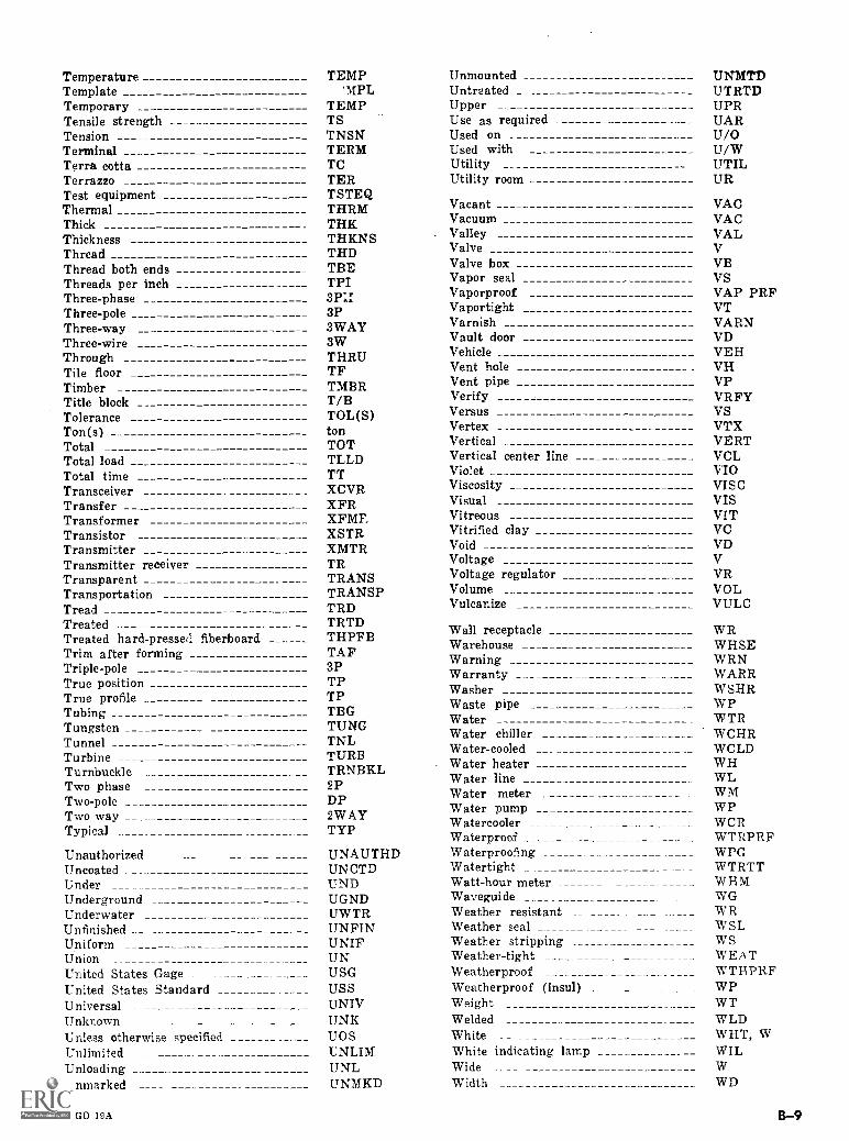
TemperatureTemplateTemporaryTensile strengthTensionTerminalTerra cottaTerrazzoTest equipmentThermalThickThicknessThreadThread both endsThreads per inchThree-phaseThree-poleThree-wayThree-wireThroughTile floorTimberTitle blockToleranceTon(s)TotalTotal loadTotal timeTransceiverTransferTransformerTransistorTransmitterTransmitter receiverTransparentTransportationTreadTreatedTreated hard - pressed fiberboardTrim after formingTriple-poleTrue positionTrue profileTubingTungstenTunnelTurbineTurnbuckleTwo phaseTwo-poleTwo wayTypical
UnauthorizedUncoatedUnderUndergroundUnderwaterUnfinishedUniformUnionUnited States GageUnited States StandardUniversalUnknownUnless otherwise specifiedUnlimitedUnloadingUnmarked
TEMP'1IPL
TEMPTSTNSNTERMTCTERTSTEQTHRMTHKTHKNSTHDTBETPI
3PSWAY3WTHRUTFTMBRT/BTOL(S)tonTOTTLLDTTXCVRXFRXFMTXSTRXMTRTRTRANSTRANSPTRDTRTDTHPFBTAF3PTPTPTBGTUNGTNLTURBTRNBKL2PDP2WAYTYP
UNAUTHDUNCTDUNDUGNDUWTRUNPINUNIFUNUSGUSSUNIVUNKUOSUNLIMUNLUNMKD
UnmountedUntreatedUpperUse as requiredUsed onUsed withUtilityUtility room
VacantVacuumValleyValveValve boxVapor sealVaporproofVaportightVarnishVault doorVehicleVent holeVent pipeVerifyVersusVertexVerticalVertical center lineVioletViscosityVisualVitreousVitrified clayVoidVoltageVoltage regulatorVolumeVulcanize
Wall receptacleWarehouseWarningWarrantyWasherWaste pipeWaterWater chillerWater-cooledWater heaterWater lineWater meterWater pumpWatercoolerWaterproofWaterproofingWatertightWatt-hour meterWavegui de _
Weather resistantWeather sealWeather strippingWeather-tightWeatherproofWeatherproof (insul)WeightWeldedWhiteWhite indicating lampWideWidth
UNMTDUTRTDUPRUARU/OU/WUTILUR
VACVACVALVVBVSVAP PRFVTVARNVDVEHVHVPVRFYVSVTRVERTVCL410VISCVISVITVCVDVVRVOLVULC
WRWHSEWRNWARRWSHRWPW TRWCHRWCLDWHWLWIVI
WPWCRWTRPRFWPGWTRTTW HWGWRWSLWSWEATWTHPRFWPWTWLDWHT, WWIL
WD
AGO 19A B-9

Width across flats WAF Wood jalousie WJWind WD Wood panel WDPWind direction WDIR Wood-shingle roof WSRWindow WDO Work WKWindow dimension WD Work benct, WBWindshield WSHLD Working WKGWire mesh WM Working pressure WPRWiring WRG Working steam pressure WSPWith (comb form) W/ Workshop WKSWith equipment and spare parts W/E&SP Wrought iron WIWithdrawn W/DWithout W/O Year YR
Without equipment and spare parts W/O E&SP Yellow YEL, Y
Wood WDYellow indicating lampYield point (psi)
YILYP
Wood door WDWood door and frame WDF Zone A
B-10 AGO 19A
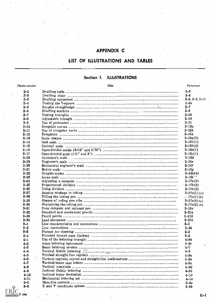
APPENDIX C
LIST OF ILLUSTRATIONS AND TABLES
Figure number
Section I. ILLUSTRATIONS
Title Paragraph
2-1 Drafting table 2-22-2 Drafting chair 2-42-3 Drafting equipment 2-5,2-9,2-112-4 Testing the T-square 2-6c2-5 Parallel straightedge , 2-72-6 Drafting machine 2-82-7 Testing triangles 2-9b2-8 Adjustable triangle 2-102-9 Use of protractor 2-112-10 Irregular curves 2-12a2-11 Use of irregular curve 2-12b2-12 Templates 2-15a2-13 Scale shapes 2-16a(3)2-14 Inch scale 2-16b(1)2-15 Decimal scale 2-16b(2)2-16 Open-divided scales (3/16" and 3/32") 2-16c(1)2-17 Open-divided scale (11 /2" and 3") 2-16c(1)2-18 Architect's scale 2-16d2-19 Engineer's scale 2-16e2-20 Mechanical engineer's scale 2-1612-21 Metric scale 2-16g2-22 Graphic scales 2-16h(4)2-23 Invar scale 2-16i'2-24 Adjusting a compass 2-17a(5)2-25 Proportional dividers 2-17b(2)2-26 Using dividers 2-171)(3)2-27 Routine mishaps in inking 2-17c(1) (a)2-28 Filling the inking pen . 17c(1) (b)2-29 Shapes of ruling pen nibs 2-17c(2) (a)2-30 Sharpening the inking pen 2-17c(2)( b)2-31 Drop compass and railroad pen 2-18c2-32 Standard and mechanical pencils 2-21a2-33 Pencil points 2-21b2-34 Lead sharpener 2-21b3-1 Line characteristics and conventions 3-23-2 Line conventions 3-2b3-3 Format for drawing 3-33-4 Finished format sizes (inches) 3-84-1 Use of the lettering triangle 4-6b4-2 Ames lettering instrument 4-6c4-3 Basic lettering strokes 4-74-4 Vertical Gothic lettering -.. 4-94_5 Vertical straight-line capitals 4-9a4-6 Vertical capitals, curved and straight-line combinations 4 -9b4-7 Vertical- lower case letters 49c4-8 Vertical numerals 4-9d4-9 Inclined Gothic lettering 4-104-10 Inclined letter formation 4-104-11 Mechanical lettering set 4-145-1 Base_line systems 5-6a5-2 X and Y coordinate system 5-6b
AGO 19A C-1
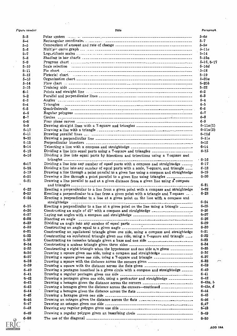
Figure numbiz. Title Paragraph
5-3 Polar system 5-6e5-4 Rectangular coordinates 5-75-5 Comparison of amount and rate of change 5-9e5-6 Multipir curve graph 5-11c5-7 LogLrithmie scales 5-145-8 Shading in bar charts 5-15a5-9 Progress chart 5-16,5-175-10 Scale selection 5-16d5-11 Pie chart 6-185 -12 Pictorial chart 5-195-13 Organization chart 5-20a5-14 Flow chart 5-20b5-15 Training aids 5-226-1 Points and straight line 6-26-2 Parallel and perpendicular lines 6-36-3 Angles 6-46-4 Triangles 6-56-5 Quadrilaterals 6-66-6 Regular polygons 6-76-7 Circles _. 6-86-8 Four plane curves 6-96-9 Drawing straight lines with a T-square and triangles 6-11a(1)6-10 Drawing a line with a triangle 6-11a(2)6-11 Drawing parallel lines 6-11d6-12 Drawing a perpendicular line 6-11e6-13 Perpendicular bisectors 6-126-14 Trisecting a line with a compass and straightedge 6-146-15 Dividing a line into equal parts using a T-square and triangles 6-156-16 Dividing a line into equal parts by bisections and trisections using a T-square and
triangles 6-166-17 Dividing a line into any number of equal parts with a compass and straightedge
,6-17
6-18 Dividing a line into any number of equal parts with a scale, T-square, and triangle 6-186-19 Drawing a line through a point parallel to a given line using a compass and straightedge 6-196-20 Drawing a line through a point parallel to a given line using triangles 6-206-21 Drawing a line parallel to and at a given distance from a given line using ii compass
and triangles 6-216-22 Erecting a perpendicular to a line from a given point with a compass and straightedge 6-226-23 Erecting a perpendicular to a line from a given point with a triangle and T-square ._ . 6-236-24 Erecting a perpendicular to a line at a given point on the line with a compass and
straightedge 6-246-25 Erecting a perpendicular to a line at a given point on the line using a triangle 6-256-26 Constructing an angle of 45° with a compass and straightedge 6-266-27 Laying out angles with a compass and straightedge 6-276-28 Bisecting an angle 6-286-29 Dividing an angle into any number of equal parts 6-296-30 Constructing an angle equal to a given angle 6-306-31 Constructing an equilateral triangle given one side, using a compass and straightedge 6-316-32 Constructing an equilateral triangle given one side, using a T-square and triangle 6-326-33 Constructing an isosceles triangle given a base and one side 6-336-34 Constructing a scalene triangle given three sides 6-346-35 Constructing a right triangle when the hypotenuse and one side a,'e given 6-356-36 Drawing a square given one side, using a compass and straightedge 6-366-37 Drawing a square given one side, using a T-square and triangle 6-376-38 Drawing a square with the distance across the corners given 6-386-39 Drawing a square with the distance across the flats given 6-396-40 Drawing a pentagon inscribed in a given circle with a compass and straightedge 6-406-41 Drawing a regular pentagon given one side 6-416-42 Drawing a pentagon given one side, using a protractor and straightedge 6-426-43 Drawing a hexagon given the distance across the corners 6-43d, b6-43 Drawing a hexagon given the distance across the cornerscontinued 6-43c, d6-44 Drawing a hexagon given the distance across the flats 6-446-45 Drawing a hexagon given one side 6-456-46 Drawing an octagon given the distance across the flats 6-466-47 Drawing an octagon given one side 6476-48 Drawing any regular polygon given one side
61.48
6-49 Drawing a regular polygon given an inscribing circle 6-496-50 The use of the diagonal 6-50
C-2 AGO 19A
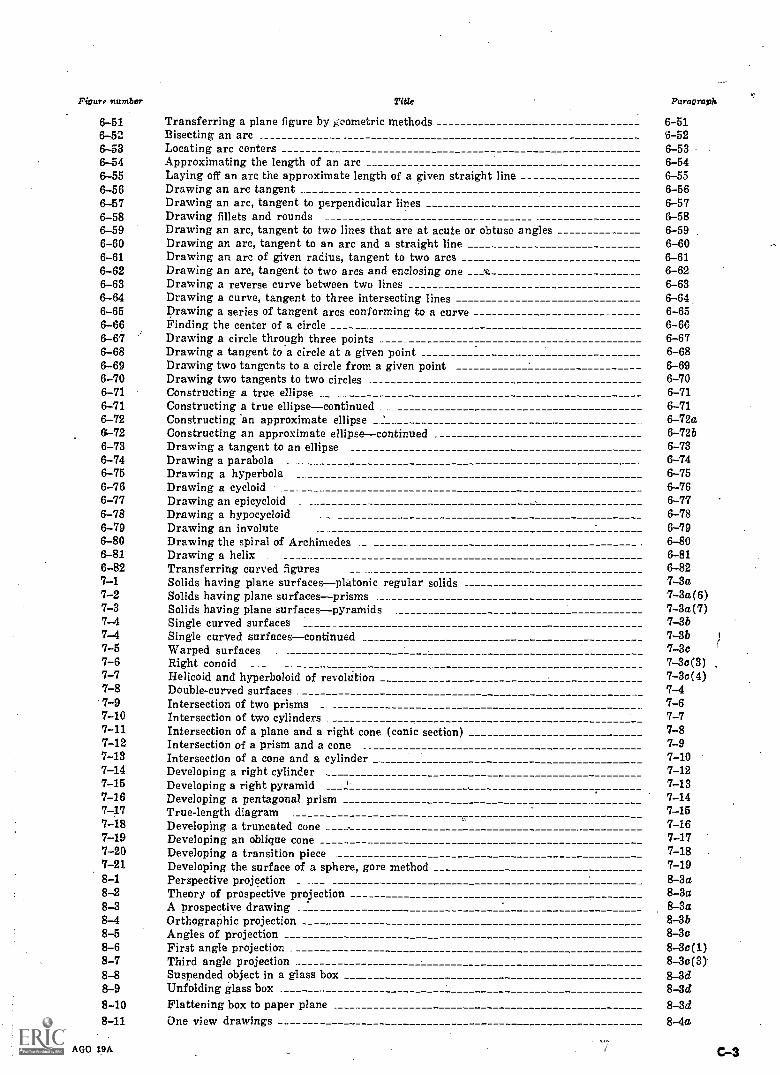
Figure number Title Paragraph
6-51 Transferring a plane figure by geometric methods 6-516-52 Bisecting an arc 6-526-53 Locating arc centers 6-536-54 Approximating the length of an arc 6-546-55 Laying off an are the approximate length of a given straight line 6-556-56 Drawing an arc tangent 6-566-57 Drawing an arc, tangent to perpendicular lines 6-576-58 Drawing fillets and rounds 6-586-59 Drawing an arc, tangent to two lines that are at acute or obtuse angles 6-596-60 Drawing an arc, tangent to an arc and a straight line 6-606-61 Drawing an arc of given radius, tangent to two arcs 6-616-62 Drawing an arc, tangent to two arcs and enclosing one 6-626-63 Drawing a reverse curve between two lines 6-636-64 Drawing a curve, tangent to three intersecting lines 6-646-65 Drawing a series of tangent arcs conforming to a curve 6-656-66 Finding the center of a circle 6-666-67 Drawing a circle through three points 6-676-68 Drawing a tangent to a circle at a given point 6-686-69 Drawing two tangents to a circle from a given point 6-696-70 Drawing two tangents to two circles 6-706-71 Constructing a true ellipse 6-716-71 Constructing a true ellipsecontinued 6-716-72 Constructing an approximate ellipse " 6-72a6-72 Constructing an approximate ellipsecontinued 6-72b6-73 Drawing a tangent to an ellipse 6-736-74 Drawing a parabola 6-746-75 Drawing a hyperbola 6-756-76 Drawing a cycloid 6-766-77 Drawing an epicycloid 6-776-78 Drawing a hypocycloid 6-786-79 Drawing an involute 6-796-80 Drawing the spiral of Archimedes 6-806-81 Drawing a helix 6-816-82 Transferring curved figures 6-827-1 Solids having plane surfacesplatonic regular solids 7-3a7-2 Solids having plane surfacesprisms 7 -3a(6)7-3 Solids having plane surfacespyramids 7-3a(7)7-4 Single curved surfaces 7-3b7-4 Single curved surfacescontinued 7-3b7-5 Warped surfaces 7-3c7-6 Right conoid 7-30(3)7-7 Helicoid and hyperboloid of revolution 7 -3c(4)7-8 Double-curved surfaces . 7-47-9 Intersection of two prisms 7-67-10 Intersection of two cylinders 7-77-11 Intersection of a plane and a right cone (conic section) 7-87-12 Intersection of a prism and a cone 7-97-13 Intersection of a cone and a cylinder 7-107-14 Developing a right cylinder 7-127-15 Developing a right pyramid 7-137-16 Developing a pentagonal prism 7-147-17 True-length diagram 7-157-18 Developing a truncated cone 7-167-19 Developing an oblique cone 7-177-20 Developing a transition piece 7-187-21 Developing the surface of a sphere, gore method 7-198-1 Perspective projection 8-3a8-2 Theory of prospective projection 8-3a8-3 A prospective drawing 8-3a8-4 Orthographic projection 8-3b8-5 Angles of projection 8-3c8-6 First angle projection 8 -3c(1)8-7 Third angle projection 8 -3c(3)8-8 Suspended object in a glass box 8-3d8-9 Unfolding glass box 8-3d8-10 Flattening box to paper plane 8-3d8-11 One view drawings 8-4a
AGO 19A
Figure number Title Paragraph
8-12 Two view drawings 8-458-13 Partial views 8-4cS 14 Three view selection 8-4cl8-15 Lie lined surfaces 8-5a8-16 Oblique surfaces 8-558-17 Curved surfaces 8-5c8-18 Rounds and fillets 8-6a8-19 Runouts with different shape intersecting members 8-6d8-20 Runouts with different shape intersecting webs 8-6d8-21 Runouts W. rminating at pcints of tangency 8-6d8-22 Trans:'er by measurement 8-88-23 Transfer with T-square and triangle 8-88-24 Transfer with miter line 8-83-25 Hidden lines 8-9a8-26 The cutting plane symbol 8-10c8-27 Section lines 8-10e8-28 Outline sectioning 8-11a8-29 Full sectioning 8-11b8-30 Half sectioning 8-11e8-31 Offset sectioning 8-11d8-32 Broken-out sectioning 8-11e8-33 Revolved sectioning 8-11f8-34 Removed sectioning 8-11g8-35 Thin sectioning 8-1111,8-36 Section through rib 8-12a8-37 Alternate sectioning 8-12b8-38 Assembly sectioning 8-12c8-39 Alined holes and ribs 8-12d8-40 Alined spokes 8-12d8-41 Primary auxiliary view 8-13b8-42 Secondary auxiliary view 8-13c8--43 Partial auxiliary view 8-13d8-44 Constructing primary auxiliary views 8-13e8-45 Constructing secondary auxiliary views 8-13/8-46 Exploded views 8-149-1 From orthographic to isometric projection 9-469-2 Isometric axes 9-4b9-3 From isometric projection to isometric drawing 9-5a9-4 Various isometric positions 9-5c9-5 Inclined surface 9-6b9-6 Isometric drawing of specific angles 9-79-7 Isometric circles 9-8a9-8 Isometric circle in rear 9-8b9 -9 Isometric arcs 9-99-10 Isometric curve 9-109-11 Isometric reverse axes 9-119-12 Isometric sections 9-129-13 Sketching on isometric graph paper 9-139-14 Dimensioning isometric drawings 9-149-15 Oblique drawing 9-15a9-16 Cavalier and cabinet projections 9-15b9-17 To avoid distortion 9-169-18 Various ways of drafting oblique drawings 9-179-19 Oblique circles 9-189-20 Sketching straight lines 9-219-21 Radial method of sketching circles 9-22a9-22 Outline method of sketching circles 9-22b9-23 Hand compass method of sketching circles 9-22c9-24 Paper strip method of sketching circles 9-22d9-25 Ellipse, paper strip method 9-239-26 Sketching a simple object 9-25b9-27 Application of isometric sketching 9-269-28 Oblique sketching 9-279-29 One point prospective (sketched) 9 -28a9-30 Two point prospective (sketched) 9-2869-31 Shade lines 9-30a9-32 Line shading and tone shading 9-30b10-1 Defining geometric characteristics 10-2
C-4 AGO 19A
Figure number Title Paragraph
10-2 Size and location dimensions 10-210-3 Dimension lines with numerals 10-3a10-4 Spacing of dimension lines 1O-3b10-5 Angle dimensions 10-3c10-6 Use of extension lines 10-410-7 Intersecting extension lines 10-410-8 Leaders 10-510-9 Typical arrowheads 10-610-10 Finish marks _ 10-710-11 Reading direction of figures 10-1010-12 Grouping and staggering dimensions 10-11b10-13 Rectangular and angular dimensions 10-11d10-14 Overall dimensions 10-11f10-15 Dimensioning in limited space _ 10-11g10-16 Dimensioning large circles 10-11h10-17 Dimensioning small circles 10-11i10-18 Dimensioning arcs 10-11j10-19 Dimensioning holes 10-11110-20 Locating holes by centerline coordinates 10-11m(1)10-21 Locating holes by polar coordinates 10-11m(4)10-22 Locating holes by symmetrical coordinates 10-11m (5)10-23 Dimensioning spherical surfaces 10-11n10-24 Dimensioning slots and surfaces with round ends 10-11010-25 Dimensioning chamfers 10-11p10-26 Dimensioning tapers 10-11q(2)10-27 Dimensioning angular surfaces 10-11s10-28 Dimensioning keys and keyways 10-11t10-29 Knurls for decoration or gripping 10-11u10-30 Dimensions from datum lines 10-12a10-31 Continuous progressive dimensioning 10-12b(1)10-32 Noncontinuous progressive dimensioning 10- 12b(2)10-33 Specific and general notes 10-14a11-1 Blueprint process 11-3a11-2 Diazoprint process 11-6a11-3 Camera process 11-8a11-4 Sun frame 11-9b(1)11-5 Developing tube 11-9b(2)11-6 Modified sun frame 11-9b(3)
Section II. TABLES
Table number Title Paragraph-1 Finished Format Sizes (Inches) 3-4
4-1 Character Sizes 4-6a11-1 Duplicating Methods, Contact Process _ 11-10a11-2 r aplicating Methods, Camera Process _ 11-10a
AGO 19A C-5
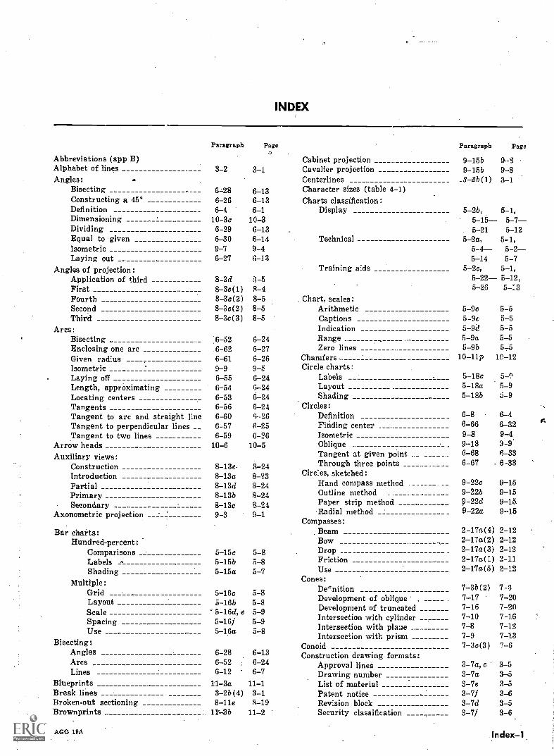
INDEX
Abbreviations (app B)Alphabet of linesAngles:
BisectingConstructing a 45°Definition
Paragraph
3-2
6-286-266-4
Page.7
3-1
6-136-136-1
Cabinet projectionCavalier projectionCenterlinesCharacter sizes (table 4-1)Charts classification:
Display
Paragraph
9-15b9-15b
_3-2b(1)
5-2b,
Page
9 39-83-1
5-1,Dimensioning 10-3c 10-3 5-15 5 -7-Dividing 6-29 6-13 5 -21 5-12Equal to given 6-30 6-14 Technical 5-2a, 5-1,Isometric 9-7 9-4 5-4 5-2--Laying out 6-27 6-13 5-14 5-7
Angles of projection: Training aids 5-2c, 5-1,Application of third 8-3d 3-5 5-22 5-12,First 8-3c(1) 8-4 5-26 5-13Fourth 8-3c(2) 8-5 Chart, scales:Second 8-3c(2) 8-5 Arithmetic 5-9c 5-5Third 8-3c(3) 8-5 Captions 5-9c 5-5
Arcs: Indication 5-9d 5-5Bisecting 6-52 6-24 Range 5-9a 5-5Enclosing one arc .6 -62 6-27 Zero lines 5 -9b 5-5Given radius 6-61 6-26 Chamfers .. 10-11p 10-12Isometric 9-9 9-5 Circle charts:Laying off 6-55 6-24 Labels 5-18c 5.-1
Length, apprOximating 6-54 6-24 Layout 5-18a 5-9Locating centers 6-53 6-24 Shading 5-18b 5-9Tangents 6-56 6-24 Circles:Tangent to arc and straight line 6-60 6 26 Definition 6-8 6-4Tangent to perpendicular lines __ 6-57 8-25 Finding center 6-66 6-32Tangent to two lines 6-59 6-26 Isometric 9-8 9-4
Arrow heads 10-6 10-5 Oblique 9-18 9-9'
Auxiliary views: Tangent at given point __ _ 6-68 6-33
Construction 8-13e 8-24 Through three points ____ 6-67 6-33
Introduction 8-13a 8-23 Circles, sketched:
Partial 8-13d 8-24 Hand compass method ._ 9-22c 9-15
Primary 8-13b 8-24 Outline method 9-22b 9-15
Secondary 8-13c 8-24 Paper strip method 9-22d 9-15
Axonometric projection 9-3 9-1 Radial method 9-22a 9-15Compasses:
Bar charts: Beam 2-17a(4) 2-12Hundred-percent: Bow 2-17a(2) 2-12
Comparisons 5-15c 5-8 Drop ___ 2-17a(3) 2-12
Labels 5-15b 5-8 Friction 2-17a(1) 2-11
Shading 5-15a 5-7 Use 2-17a(5) 2-12
Multiple:GridLayoutScaleSpacingUse
5-16c5-16b5-16d, e5-16f5-16a
5-85-85-95-95-8
Cones:DenitionDevelopment of obliqueDevelopment of truncatedIntersection with cylinderIntersection with placeIntersection with prism
7-3b(2)7-177-167-107-87-9
7-37-207-207467-127-13
Bisecting: Conoid 7-3c(3) 7-6Angles 6-28 6-13 Construction drawing formats:ArcsLines
6-526-12 '
6-246-7
Approval linesDrawing number
3-7a, c3-7a
3-53-5
Blueprints 11-3a 11-1 List of material 3-7e 3-5Break lines 3-2b(4) 3-1 Patent notice 3-7f 3-6Broken-out sectioning 8-11e 8-19 Revision block 3-7d 3-5Brownprints 11:-.3b 11-2 Security classification 3-7f 3-6
AGO 19A Index-1.
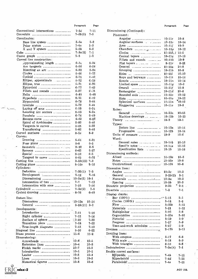
Paragraph Page
Conventional intersections 7-5d 7-11Convolute 7-35(3) 7-5Coordinates.:
Base line system 5-6a 5-2Polar system 5-6c 5-3X and Y system 5-6b 5-2
Cube 7-3a(2) 7-1Curve graph 5-8 3-3Curved line construction:
approximating length 6-54 6-24Arc tangents 6-56 6-24Bisecting an arc 6-52 6-24Circles 6-66 6-32Cycloid 6-76 0-40Ellipse, approximate 6-72 C-33Ellipse, true 6-71 6-33Epicycloid 6-77Fillets and rounds 6-57 C-25Helix 6-81 6-46Hyperbola 6-75 610Hypocycloid 6-78 6-44Involute 6-79 6-44Laying off arcs 6-55 6-24Locating arc centers 6-53 6-24Parabola 6-74 6-40Reverse curve 6-63 6-27Spiral of Archimedes 6-80 6-46Tangents to curves 6-65 6-32Transferring 6-82 6-46
Curved surfaces 8-5c 8-9Curves:
Drawing 6-64 6-31Four plane 6-9 6-5
- Isometric 9-10 9-5Reverse 6-63 6-27Special 6-10 6-5Tangent to curve 6-65 6-S2
Cutting line 3-2b(12) 3 -3Cutting plane 8-10c 8-16Cylinders:
Definition 7-3b(1) 7-3Development 7-12 7-16Dimensioning 10-2a(2) 10-1Intersection of two 7-7 7-12Intersection with cone 7-10 7-16
Cylindroid 7-3c(2) 7-6Cycloid drawing 6-76 6-40
Datum line:Dimensions 10-12a 10-14General 3-2b(11) 3-3
Developments:Introduction 7-11 7-16Right cylinder 7-12 7-16Surface of sphere :,7-19 7-22Transition piece 7-18 7-22True-length diagrams 7-15 7-18
Diagonal line 6-50 6-22Diazo process 11-6 11-2Dimensioning:
Arrowheads 10 -6 10-5Extension lines 10-4 10-3Finish marks 10-7 10-5Introduction 10-1 10-1Leader 10-5 10-4Lines 10-3 10-3Numerical figures 10-8 10-6
Index4
Paragraph Page
Dimensioning (Continued):Placement:
Angular 10 -lie 10-8Angular surfaces 10-11s 10-14Arcs 10-11j 10-9Chamfers 10 -lip 10-12Circles 10-11h, i 10-9Conical tapers 10-11q 10-13Fillets and rounds 10-11k 10-9Flat tapers 8-11r 8-21General 10-11a 10-8Grouping 10 -lib 10-8Holes __ 10-111 10-10Keys and keyways 10 -lit 10-14Knurls 10-11u 10-14Limited space 10-11g 10-9Overall 10-11f 10-8Rectangular 10 -lid 10-8Rounded ends 10-110 10-12Slots 10-110 10-12Spherical surfaces 10-11n "10-12Staggering 10 -lie 10-8
Rules:General 10-13a 10-15Machine drawings . 10-13b 10-15
Theory 10-2 10-1Types:
Datum line 10-12a 10-14Progressive 10-12b 10-14
Units of measure 10-9 10-6Word:
General notes 10-14b 10-16Specific notes . _ 10-14a 10-16Specification lists _ _______ 10-15 10-16
Dimensioning methods:Alined 10-10a 10-6Notes 1010c 10-8Unidirectional 10-10b 10-8
Dimension lines:Angles 10-3c 10-3General 3-2b(2) 3-1Numerals 10-3a 10-3Spacing 10-3b 10-3
Dimetric projection 9-3b 9-1Directrix 7-2 7-1Display charts:
Bar (100%) ' 5-15 5-1Circles -(100%) 5-18 5-9Flow 5-20b 5-11Materials 5-21 5-12Multiple-bar 5-16 5-8Organization 5-20a 5-10Pictorial 5-19 5-9Progress 5-17 5-9Time-and-work schedules 5-17 5-9
Dividers 2-17b 2-13Dividing lines:
With compass 6-17 6-8With scale __ 6-18 6-9With triangles 6-16 6-8
Dodecahedron 7-3a(4) 7-1Double curved surfaces:
Ellipsoids. 7-4b .7 -11Wyperbolold 7-4d 7-11Paraboloid' 7-4c 7-11
AGO 19A
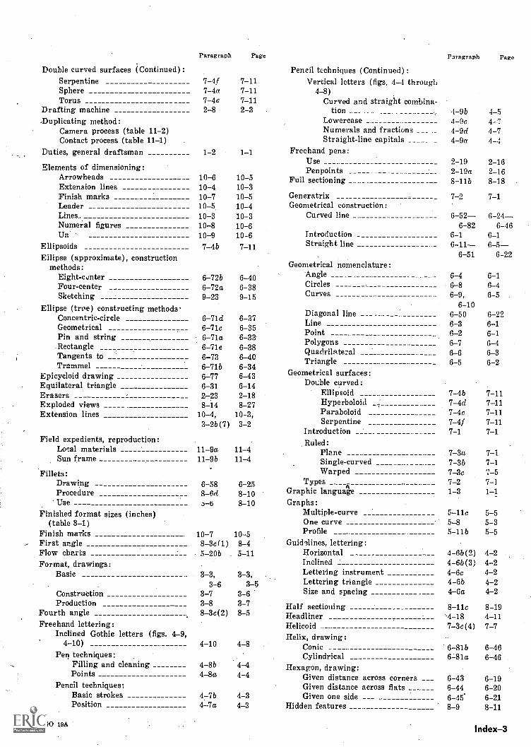
Double curved surfaces (Continued) :SerpentineSphereTorus
Drafting machine.Duplicating method:
Camera process (table 11-2)Contact process (table 11-1)
Duties, general draftsman 1-2 1-1
Elements of dimensioning:Arrowheads 10-6Extension lines 10-4Finish marks 10-7Leader 10-5Lines.. 10-3Numeral figures 10-8Ur.' 10-9
Ellipsoids 7 -4bEllipse (approximate), construction
methods:Eight - tinter 6-72b 6-40Four-center 6-72a 6-38Sketching 9-23 9-15
Ellipse (true) constructing methodsConcentric-circle 6-71d 6-37Geometrical 6 -71c 6-35Pin and string 6-71a 6-33Rectangle 6-71e 6-38Tangents to 6-73 6-40Trammel 6-71b 6-34
Epicycloid drawing 6-77 6-43Equilateral triangle 6-31 6-14Erasers 2-23 2-18Exploded views 8-14 8-27Extension lines 10-4, 10-3,
3-2b(7) 3-2
Paragraph Page Paragraph Page
Pencil techniques (Continued) :7-4f 7-11 Vertical letters (figs. 4-4 through7-4a 7-11 4-8)7-4e 7-11 Curved and straight combina-2-8 2-3 tion 4-9b 4-5
Lowercase 4-9c 4-7Numerals and fractions __ 4-9d 4-7Straight-line capitals ____ _ 4-9a 4-4
10-510-310-510-410-310-610-67-11
Field expedients, reproduction:Local materialsSun frame
Fillets:DrawingProcedureUse
Finished format sizes (inches)(table 3-1)
Finish marksFirst angleFlow chartsFormat, drawings:
Basic
ConstructionProduction
Fourth angleFreehand lettering:
Inclined Gothic letters (figs. 4-9,4-10) 4-10 4-8
Pen techniques:Filling and cleaningPoints 4-8a 4-4
Pencil techniques:Basic strokesPosition
11-9a 11-4
Freehand pens:UsePenpoints
Full sectioning
GeneratrixGeometrical construction:
Curved line 6-52 6 -24-6-82 6-46
Introduction 6-1 6-1Straight line 6-11 6 -5-
6-51 6-22
2 -19 2-162-19a 2-168-11b 8-18
7-2 7-1
Geometrical nomenclature:Angle 6-4 6-1Circles 6-8 6-4Curves 6-9, 6-5
6-10Diagonal line 6-50 6-22Line 6-3 6-1Point 6-2 6-1Polygons 6-7 6-4Quadrils teral 6-6 6-3Triangle 6-5 6-2
Geometrical surfaces:Double curved:
Ellipsoid 7-4b 7-11Hyperboloid 7-4d 7-11Paraboloid 7-4c 7-11Serpentine 7-4f 7-11
Introduction 7-1 7-1Ruled:
Plane 7-3a 7-111-9b 11-4 Single-curved 7-3b 7-1
Warped 7-3c 7-56-58 6-25 Types 7-2 7-18-6d 8-10 Graphic language 1-3 1-13-6 8-10 Graphs:
Multiple-curve 5 -lie 5-5One curve 5-8 5-3Profile 5-11b 5-5
Guidelines, lettering:Horizontal 4-6b(2) 4-2Inclined 4-6b(3) 4-2Lettering instrument 4-6c 4-2Lettering triangle 4-6b 4-2Size and spacing 4-6a 4-2
10-7 10 58-3c(1) 8-45-20b 5-11
3-3,3-6
3-73-88 -3c(2)
3-3,3-5
3-63-78-5
Half sectioning 8 -lie 8-19Headliner -4-18 4-11Helicoid 7 -3c(4) 7-7Helix, drawing:
Conic 6-81b 6-46Cylindrical 6-81a 6-46
4-8b 4-4 Hexagon, drawing:Given distance across corners 6-43 6-19Given distance across flats 6-44 6-20
4-7b 4-3 Given one side 6-45 6-214-7a 4-3 Hidden features _ 8-9 8-11
AGO 19AIndex-3
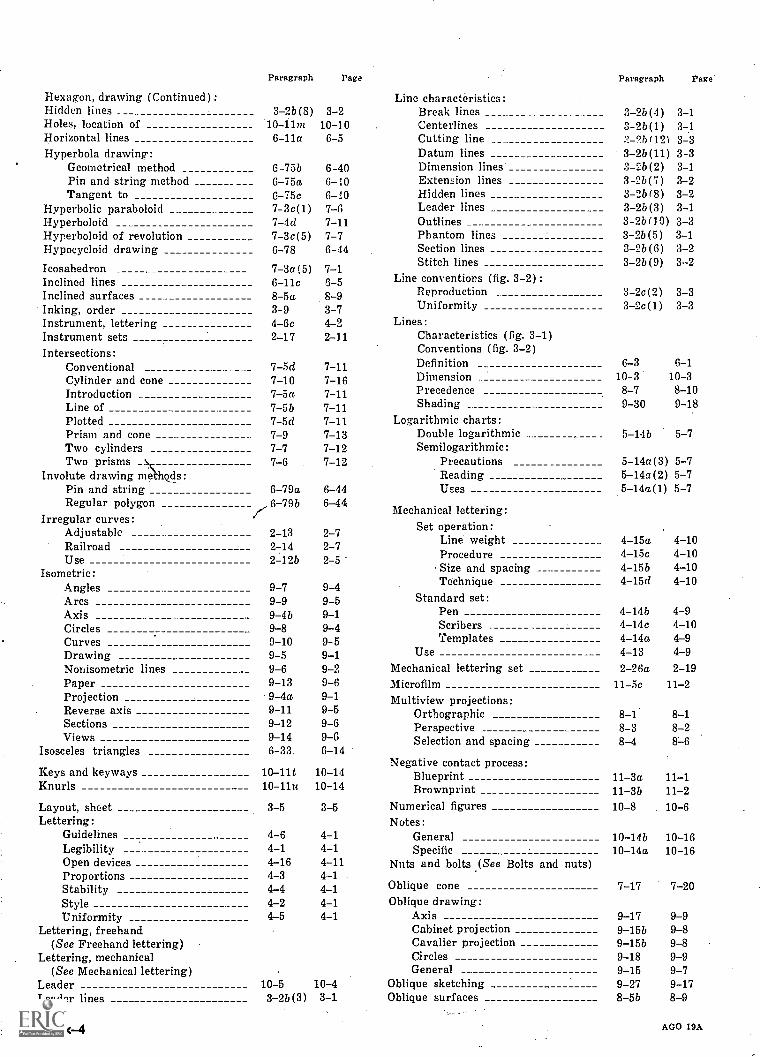
Hexagon, drawing (Continued):Hidden linesHoles, location of
Paragraph
3-2b (8)10-11m
Page
3-210-10
Line characteristics:Break linesCenterlines
Paragraph Page
3-2b(4) 3-13-2b(1) 3 -1
Horizontal lines 6-11a 6-5 Cutting line 2b(121 3-3Hyperbola drawing: Datum lines 3-2b(11) 3-3
Geometrical method G-75b 6-40 Dimension lines 3 -2b(2) 3-1Pin and string method 6-75a 6-10 Extension lines 3-2b(7) 3-2Tangent to G-75c 6-10 Hidden lines 3 -2b(8) 3-2
Hyperbolic paraboloid __ 7-3c(1) 7-G Leader lines 3 -2b(3) 3-1Hyperboloid 7-4d 7-11 Outlines 3-2b(10) 3-3Hyperboloid of revolution 7-3c(5) 7-7 Phantom lines 3 -2b(5) 3-1Hypocycloid drawing G-78 6-44 Section lines 3 -2b(6) 3-2
Icosahedron 7-3a(5) 7-1 Stitch lines 3-2b(9) 3--2
Inclined lines 6-11c 6-5 Line conventions (fig. 3-2) :Inclined surfaces 8-5a 8-9 Reproduction 3-2c(2) 3-3
Inking, order 3-9 3-7 Uniformity 3-2c(1) 3-3
Instrument, lettering 4-5c 4-2 Lines:Instrument sets 2-17 2-11 Characteristics (fig. 3-1)Intersections: Conventions (fig. 3-2)
Conventional 7-5d 7-11 Definition 6-3 6-1
Cylinder and cone 7-10 7-16 Dimension 10-3 10-3
Introduction 7-5a 7-11 Precedence 8-7 8-10
Line of 7-5 b 7-11 Shading 9-30 9-18
Plotted 7-5d 7-11 Logarithmic charts:Prism and cone 7-9 7-13 Double logarithmic 5-14b 5-7Two cylinders 7-7 7-12 Sernilogarithmic:Two prisms 7-6 7-12 Precautions 5- 14a(3) 5-7
Involute drawing methods_: Reading 5-14a(2) 5-7Pin and string 6-79a 6-44 Uses 5-14a(1) 5-7Regular polygon
Irregular curves:6 -79b7 6-44 Mechanical lettering:
AdjustableRailroadUse
Isometric:
2-132 -142-12b
2-72-72-5
Set operation:Line weightProcedureSize and spacing
4-15a 4-104-15c 4-104-15b 4-10
Angles 9-7 9-4 Technique 4-15d 4-10
Arcs 9-9 9-5 Standard set:Axis 9-4b 9-1 Pen 4-14b 4-9Circles 9-8 9-4 Scribers 4-14c 4-10Curves 9-10 9-5 Templates 4-14a 4-9
Drawing 9-5 9-1 Use 4-13 4-9Nonisometric lines 9-6 9-2 Mechanical lettering set 2-26a 2-19Paper 9-13 9-6 Microfilm 11-5c 11-2Projection 9-4a 9-1 Multiview projections:Reverse axis 9-11 9-5 Orthographic 8-1. 8-1Sections 9-12 9-6 Perspective 8-3 8-2Views 9-14 9-6 Selection and spacing 8-4
Isosceles triangles 6-33. 6-14Negative contact process:
Keys and keyways 10-11t 10-14 Blueprint 11-3a 11-1Knurls 10-11u 10-14 Brownprint 11-3b 11-2Layout, sheet 3-5 3-5 Numerical figures 10-8 10-6Lettering: Notes:
Guidelines 4-6 4-1 General 10-14b 10-16Legibility 4-1 4-1 Specific 10-14a 10-16Open devices 4-16 4-11 Nuts and bolts (See Bolts and nuts)Proportions 4-3 4-1Stability 4-4 4-1 Oblique cone 7-17 7-20
Style 4-2 4-1 Oblique drawing:Uniformity 4-5 4-1 Axis 9-17 9-9
Lettering, freehand Cabinet projection 9-15b 9-8(See Freehand lettering) Cavalier projection 9-15b 9-8
Lettering, mechanical Circles 9-18 9-9(See Mechanical lettering) General 9-15 9-7
Leader 10-5 10-4 Oblique sketching 9-27 9-17Leader lines 3 -2b(3) 3-1 Oblique surfaces 8-5b 8-9
Index-4 AGO 19A
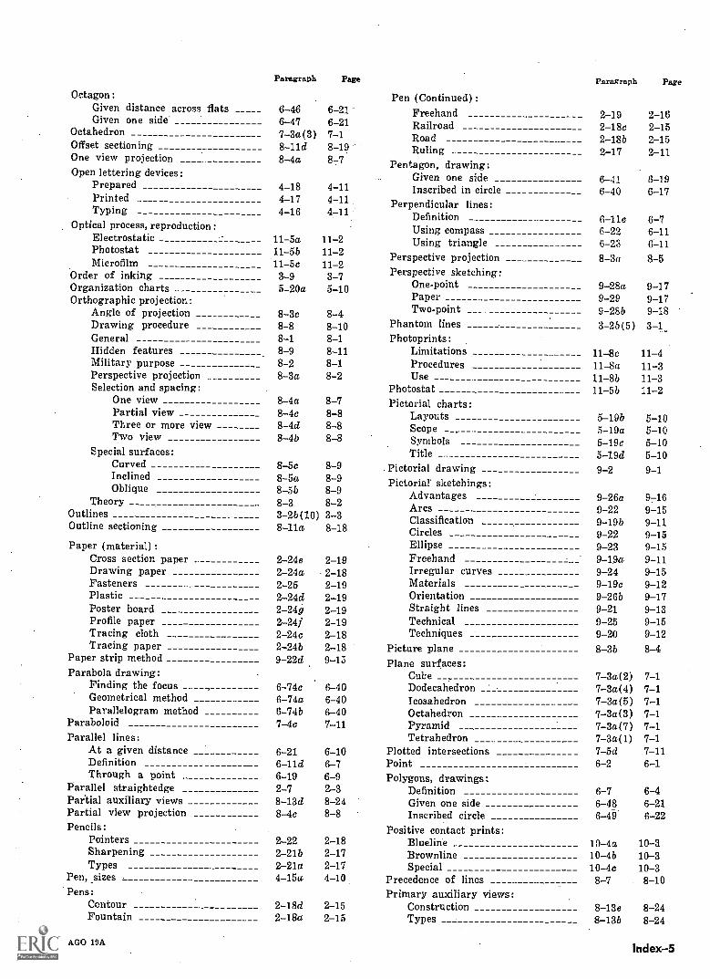
Octagon:
Paragraph Page
Pen (Continued) :
Paragraph Page
Given distance across flats 6-46 6-21 Freehand 2-19 2-16Given one side 6-47 6-21 Railroad 2-18c 2-15Octahedron 7-3a(3) 7-1 Road 2-186 2-15Offset sectioning 8-11d 8-19 Ruling 2-17 2-11One view projection 8-4a 8-7 Pentagon, drawing:Open lettering devices: Given one side 6-41 6-19Prepared 4-18 4-11 Inscribed in circle 6-40 6-17Printed 4-17 4-11 Perpendicular lines:Typing 4-16 4-11 Definition 6-11e 6-7Optical process, reproduction: Using compass 6-22 6-11Electrostatic 11-5a 11-2 Using triangle 6-23 6-11Photostat
Microfilm11-5b11-5c
11-211-2
Perspective projection 8-3a 8-5Order of inking 3-9 3-7 Perspective sketching:Organization charts 5-20a 5-10 One-point 9-28a 9-17Orthographic projection: Paper 9-29 9-17
Angle of projection 8-3c 8-4 Two-point 9-285 9-18Drawing procedure 8-8 8-10 Phantom lines 3-26(5) 3-1_General 8-1 8-1 Photoprints:Hidden features 8-9 8-11 Limitations 11-8c 11-4Military purpose 8-2 8-1 Procedures 11-8a 11-3Perspective projection 8-3a 8-2 Use 11-8b 11-3Selection and spacing: Photostat 11-5b 11-2
One view 8-4a 8-7 Pictorial charts:Partial view 8-4c 8-8 Layouts 5-19b 5-10Three or more view 8-4d 8-8 Scope 5-19a 5-10Two view 8-4b 8-8 Symbols 5-19c 5-10
Special surfaces: Title 5-19d 5-10Curved 8-5c 8-9 Pictorial drawing 9-2 9-1InclinedOblique
TheoryOutlinesOutline sectioning
8-5a8-5b8-33-26(10)8-11a
8-98-98-23-38-18
Pictorial' sketchings:AdvantagesArcsClassificationCircles
9-26a9-229-19b9-22
9-169-159-119-15
Paper (material) : Ellipse 9-23 9-15Cross section paper _ 2-24e 2-19 Freehand 9-19a 9-11Drawing paper 2-29a 2-18 Irregular curves 9-24 9-15Fasteners 2-25 2-19 Materials 9-19c 9-12Plastic 2-24d 2-19 Orientation 9-26b 9-17Poster board 2 -24g 2-19 Straight lines 9-21 9-13Profile paper 2-24f 2-19 Technical 9-25 9-15Tracing cloth 2-24c 2-18 Techniques 9-20 9-12Tracing paper 2-24b 2-18 Picture plane 8-3b 8-4
Paper strip method 9-22d 9 -13 Plane surfaces:Parabola drawing: Cube 7-3a,(2) 7-1
Finding the focus - 6-74c 6-40 Dodecahedron 7-3a(4) 7-1Geometrical method 6-74a 6-40 Icosahedron 7-3a(5) 7-1Parallelogram method 6 -74b 6-40 Octahedron 7-3a(3) 7-1
Paraboloid 7-4c 7-11 Pyramid 7-3a(7) 7-1Parallel lines: Tetrahedron 7-3a(1) 7-1
At a given distance 6-21 6-10 Plotted intersections 7-5d 7-11Definition 6-11d 6-7 Point 6-2 6-1Through a point 6-19 6-9 Polygons, drawings:
Parallel straightedge 2-7 2-3 Definition 6-7 6-4Partial auxiliary views 8-13d 8-24 Given one side 6-48 6-21Partial view projection 8-4c 8-8 Inscribed circle 6-49 6-22Pencils: Positive contact prints:
Pointers 2-22 2-18 Blue line 10-4a 10-3Sharpening 2-21b 2-17 Brown line 10-4b 10-3Types 2-21a 2-17 Special 10-4c 10-3
Pen, sizes 4-15a 4-10 Precedence of lines 8-7 8-10Pens: Primary auxiliary views:
Contour 2-18d 2-15 Construction 8-13e 8-24Fountain 2-18a 2-15 Types 8-13b 8-24
AGO 19AIndex-5
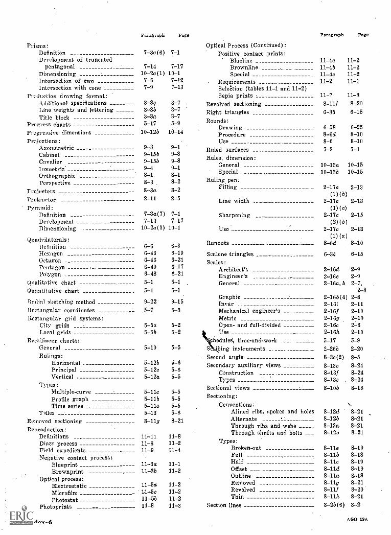
Paragraph Page Paragraph Page
Prisms:Definition 7-3a(6) 7-1Development of truncated
pentagonal 7-14 7-17Dimensioning 10-2a(1) 10-1interseetion of two 7-6 7-12Intersection with cone 7-9 7-13
Production drawing format:Additional specifications 3-8c 3-7Line weights and lettering 3-8b 3-7Title block 3-8a 3 -7
Progress charts 5-17 5-9
Progressive dimensions 10-12b 10-14
Projections:Axonometric 9-3 9-1Cabinet 9-15b 9-8Cavalier 9-15b 9-8Isometric. 9-4 9-1Orthographic 8-1Perspective 8-3 8-2
Projectors ___Protractor _.
Pyramid:Definition 7-3a(7) '7-1
Development 7-13 7-17Dimensioning 10-2a(3) 10-1
Quadrilaterals:DefinitionHexagonOctagonPentagonPolygon
Qualitative chartQuantitative chart
8-3a 8-22-11 2-5
Radial sketching methodRectangular coordinatesRectangular grid systems:
City gridsLocal grids
Rectilinear charts:GeneralRulings:
HorizontalPrincipalVertical
Types:Multiple-curveProfile graphTime series
TitlesRemoved sectioningReproduction:
DefinitionsDiazo processField expedientsNegative contact process:
BlueprintBrownprint
Optical process:Electrostatic 11-5aMicrofilm 1-1-5c
Photostat 11-5bPhotoprints 11-8
6-66-436-466-406-485-15-1
6-36-196-216-176-215-15-1
Optical Process (Continued) :Positive contact prints:
Blue line 11-4a 11-2Brown line 11-41) 11-2Special 11-4c 11-2
Requirements 11-2 11-1Selection (tables 11-1 and 11-2)Sepia prints 11-7 11-3
Revolved sectioning 8-111 8-20Right triangles 6-35 6-15
Rounds:Drawing 6-58 6-25Procedure 8-6d 8-10Use 8-6 8-10
Ruled surfaces 7-3 7-1Rules, dimension:
General 10-13a 10-15Special 10-13b 10-15
Ruling pen:Filling 2-17c 2-13
(1) (b)Line width 2-17c 2-13
(1) (a)Sharpening 2-17c 2-15
(2)(b)Use 2-17c 2-13
(1) (a)Runouts 8-6d 8-10
Scalene triangles 6-34 6-15Scales:
Architect's 2-16d 2-9Engineer's 2-16e 2-9General 2-16a, b 2-7,
2-8Graphic 2-16b(4) 2-8
9-22 9-15 2-16i 2-115-7 5-3 Mechanical engineer's ___ 2-161 2-10
Metric 2-16g 2-105-5a 5-2 Open- and full-divided 2-16c 2-85-5b 5-2 Use 2-16h 2-10
chedules, time-and-work 5-17 5-95-10 5-5 S ing instruments ___ 2-26b 2-20
Second angle 8 -3c(2) 8-5Secondary auxiliary views 8-13c 8-24
Construction 8-131 8-24Types 8-13c 8-24
Sectional views 8-10b 8-16Sectioning:
Ccnventions:Alined ribs, spokes and holes 8-12d 8-21Alternate 8-12b 8-21Through ribs and webs 8-12a 8-21Through shafts and bolts 8-12c 8-21
Types:Broken-out 8-11e 8-19Full 8-11b 8-18Half 8-11c 8-19
11-3b 11-2 Offset 8-11d 8-19Outline 8-11a 8-18Removed 8-11g 8-21Revolved 8-111 8-20Thin 8-11h 8-21
Section lines 3-2b(6) 3-2
5-12b5-12c5-12a
5-11c5-11b5-11a5-138-11g
11-1111-611-9
5-65-65-5
5-55-55-55-68-21
11-811 211-4
11-3a 11-1
11-211-211-211-3
AGO 19A
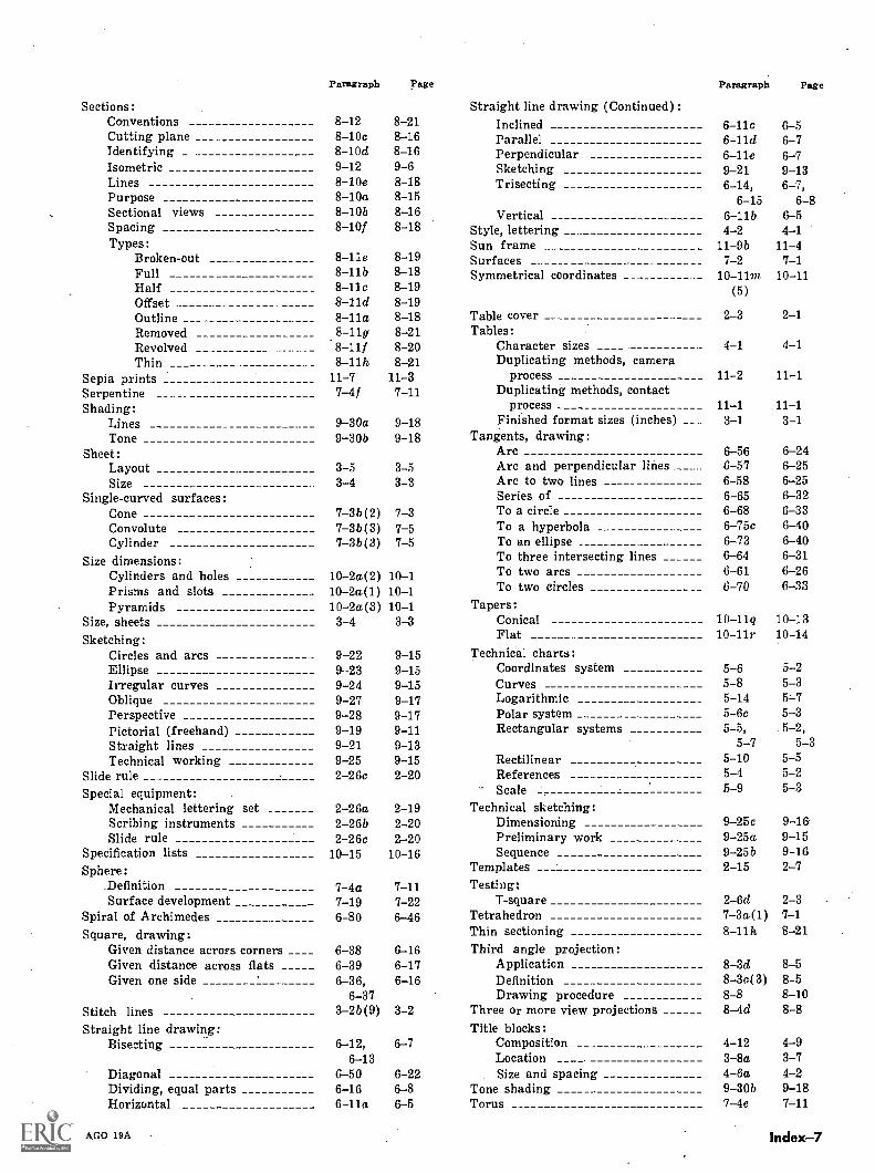
Paragraph Page
Sections:Conventions 8-12 8-21Cutting plane 8-10c 8-16Identifying 8-10d 8-16Isometric 9-12 9-6Lines ____ 8-10e 8-18Purpose 8-10a 8-15Sectional views 8-10b 8-16Spacing 8-10f 8-18Types:
Broken-out 8-11e 8-19Full 8-11b 8-18Half 8-11c 8-19Offset 8-11d 8-19Outline ___ 8-11a 8-18Removed 8-11g 8-21Revolved .8-11f 8-20Thin 8-11h 8-21
Sepia prints 11-7 11-3Serpentine 7-4f 7-11Shading:
Lines 9-30a 9-18Tone 9-30b 9-18
Sheet:Layout 3-5 3-5Size 3-4 3-3
Single-curved surfaces:Cone 7-3b(2) 7-3Convolute 7-3b(3) 7-5Cylinder 7 -3b(3) 7-5
Size dimensions:Cylinders and holes 10-2a(2) 10-1Prisms and slots 10-2a(1) 10-1Pyramids 10-2a(3) 10-1
Size, sheets 3-4 3-3Sketching:
Circles and arcs 9-22 9-15Ellipse 9 -23 9-15Irregular curves 9-24 9-15Oblique 9-27 9-17Perspective 9-28 9-17Pictorial (freehand) 9-19 9-11Straight lines 9-21 9-13Technical working 9-25 9-15
Slide rule 2-26c 2-20Special equipment:
Mechanical lettering set 2-26a 2-19Scribing instruments 2-26b 2-20Slide rule 2-26c 2-20
Specification lists 10-15 10-16Sphere:
Definition 7-4a 7-11Surface development 7-19 7-22
Spiral of Archimedes 6-80 6-46Square, drawing:
Given distance across corners 6-38 6-16Given distance across flats 6-39 6-17Given one side 6-36, 6-16
6-37Stitch lines 3-2b(9) 3-2Straight line drawing:
Bisecting 6-12, 6-76-13
Diagonal 6-50 6-22Dividing, equal parts 6-16 6-8Horizontal 6-11a 6-5
AGO 19A
Paragraph Page
Straight line drawing (Continued):Inclined 6-11c 6-5Parallel 6-11d 6-7Perpendicular 6-11e 6-7Sketching 9-21 9-13Trisecting _ 6-14, 6-7,
6-15 6-8Vertical 6-11b 6-5
Style, lettering __ 4-2 4-1Sun frame 11-9b 11-4Surfaces 7-2 7-1Symmetrical coordinates _ _ 10-11m 10-11
(5)
Table cover 2-3 2-1Tables:
Character sizes 4-1 4-1Duplicating methods, camera
process 11-2 11-1Duplicating methods, contact
process 11-1 11-1Finished format sizes (inches) 3-1 3-1
Tangents, drawing:Arc 6-56 6-24Arc and perpendicular lines 6-57 6-25Arc to two lines 6-58 6-25Series of 6-65 6-32To a circle 6-68 (3-33To a hyperbola 6-75c 6-40To an ellipse 6-73 6-40To three intersecting lines 6-64 6-31To two arcs 6-61 6-26To two circles 6-70 6-33
Tapers:Conical 10-11g 10-13Flat 10-11r 10-14
Technical charts:Coordinates system 5-6 5-2Curves 5-8 5-3Logarithmic 5-14 5-7Polar system 5-6c 5-3Rectangular systems 5-5, 5-2,
5-'7 5-3Rectilinear 5-10 5-5References 5-4 5-2Scale 5-9 5-3
Technical sketching:Dimensioning 9-25c 9-16Preliminary work 9-25a 9-15Sequence 9-25b 9-16
Templates 2-15 2-7Testing:
T-square 2-6d 2-3Tetrahedron 7-3a.(1) 7-1Thin sectioning 8-11h 8-21Third angle projection:
Application 8-3d 8-5Definition 8 -3e(3) 8-5Drawing procedure 8-8 8-10
Three or more view projections 8-4d 8-8Title blocks:
Composition 4-12 4-9Location 3-8a 3-7Size and spacing 4-6a 4-2
Tone shading 9-30b 9-18Torus 7-4e 7-11
Index-7
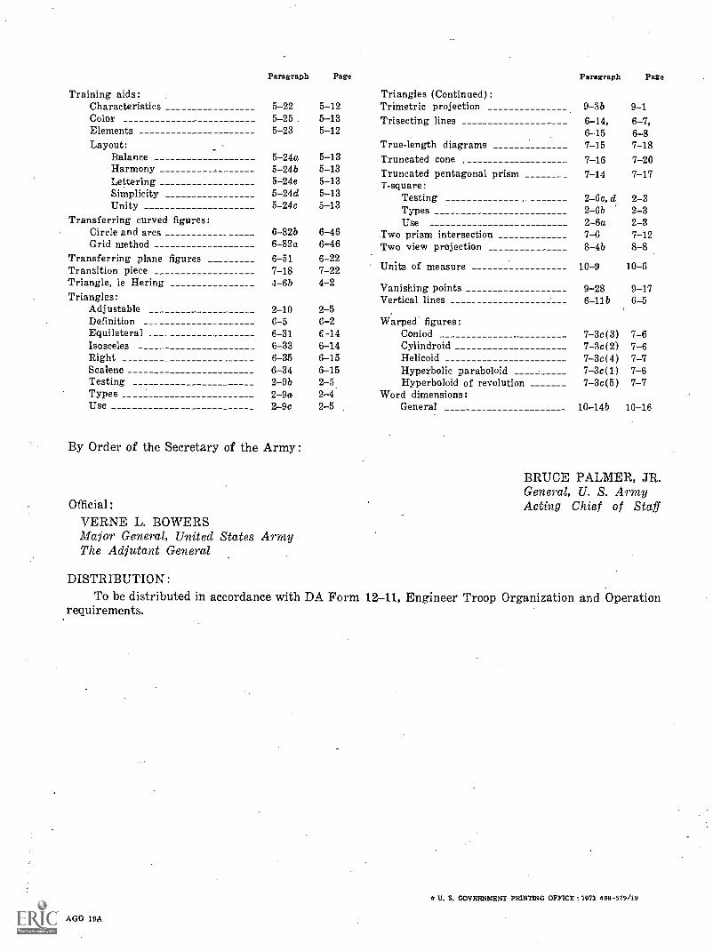
Training aids:
Paragraph Page
Triangles (Continued):
Paragraph Page
Characteristics 5-22 5-12 Trimetric projection 9-3b 9-1Color 5 -25. 5-13 Trisecting lines 6-14, 6-7,Elements 5-23 5-12 6-.15 6 -SLayout: True-length diagrams 7-15 7-18
Balance 5-24a 5-13 Truncated cone 7-16 7-20Harmony 5-24b 5-13 Truncated pentagonal prism 7-14 7-17Lettering 5-24e 5-13 T-square:Simplicity 5-24d 5-13 Testing 2-6c, d 2-3Unity 5-24c 5-13 Types 2-6b 2-3
Transferring curved figures: Use 2-6a 2-3Circle and arcs 6 -82b 6-46 Two prism intersection 7-6 7-12Grid method 6-82a 6-46 Two view projection 8-4b 8-8
Transferring plane figures 6-51 6-22Transition piece 7-18 7-22 Units of measure 10-9 10-6
Triangle, le Hering 4-6b 4-2 Vanishing points 9-28 9-17Triangles: Vertical lines 6 -lib 6-5
Adjustable 2-10 2-5Definition 6-5 6-2 Warped figures:Equilateral 6-31 C-14 Coniod 7-3c(3) 7-6Isosceles 6-33 6-14 Cylindroid 7-3c(2) 7-6Right 6-35 6-15 Helicoid 7-3c(4) 7-7Scalene 6-34 6-15 Hyperbolic paraboloid 7-3c(1) 7-6Testing 2-9b 2-5. Hyperboloid of revolution 7-3c(5) 7-7Types 2-9a 2-4 Word dimensions:Use 2-9c 2-5 General 10-14b 10-16
By Order of the Secretary of the Army:
Official:VERNE L. BOWERSMajor General, United States ArmyThe Adjutant General
DISTRIBUTION:To be distributed in accordance with DA Form
requirements.
AGO 19A
BRUCE PALMER, JR.General, U. S. ArmyActing Chief of Staff
12-11, Engineer Troop Organization and Operation
* U. E. GOVERNMENT PRINTING OFFICE 1913 488-579/19