document part number 88320 power jack - lci1.com · pdf filedeluxe heavy duty marine max....
TRANSCRIPT

1
•Installation •Operation •MaintenanceEffective 2/21/14
DOCUMENT PART NUMBER 88320
POWER JACK
RV and Marine Applications
m CAUTIONPERSONAL INJURY/PROPERTY DAMAGE
• Retract jack fully before towing.• Do not use blocks to increase height of jack. • Use 4000 lb. Heavy Duty Power Jack if you use equalizer bars between the trailer and the tow
vehicle.
INSTALLATION1. Block tires of trailer and securely support trailer tongue.2. The Atwood RV Power Jack is designed to attach to the top surface of
an A-frame type tongue having mounting holes typical of the AtwoodA-frame couplers FIG 1. Use coupler installation instructions (MPD87984) if installing coupler. The Marine Power Jack attaches to the sideof a straight tongue trailer.
3. A lower support plate must be used for side support of the RV jack onthe lower surface of the A-frame FIG 1.
HOLE DIAMETERS: Light Weight - 2.02˝ (MIN) 2.09˝ (MAX)
Deluxe / Heavy Duty - 2.20˝ 2.28˝ Hole in lower support plate must align with hole in coupler. TO ORDER LOWER SUPPORT PLATE: Light Weight - Atwood MPD 80263
Deluxe / Heavy Duty - Atwood MPD 80570 Using a 1/8˝ fillet weld, No. E6011 AWS welding rod 1/8˝ diameter, machine amps (AC or DCRP) at 160-180 with 50 volts, weld plate full length on each side to underside of A-frame. The maximum frame height is 6 inches.
4. Place RV jack through holes in coupler and lower support plate, FIG 1-A.Attach with three (3) bolts (3/8˝ dia. x 5/8˝ long, grade 5, FIG 1-B. NOTE:Torque bolts to 15 foot lbs. minimum /20 foot lbs. max. Note: There must be metal to metal contact between jack and coupler. The three mounting bolts with attached star washers must be used. The star washers are designed to remove paint on the surface of jack flange. The bolts also should remove paint from the mounting holes in coupler. If a grounding problem occurs (i.e. no power) check these two surfaces to be sure there is metal to metal contact between jack and coupler. For wiring, see WIRING ILLUSTRATIONS FIG 2 & 3.
5. Attach jack as shown.
6. Route wire lead from motor along trailer tongue to battery. Secure leadto jack housing and trailer frame using cable ties or equivalent.
7. Remove fuse from fuse holder. Connect the wire lead from the jackdirectly to the positive (+) terminal of the battery. Replace the fuse intothe fuse holder. For auxiliary battery, connect lead to auxiliary batterypositive (+) terminal so that jack may be used when connected to 115v.For additional wire, use #10 stranded copper wire or larger.
8. After reinstalling fuse, check installation by pressing switch marked “EXT”for jack extension or “RET” to retract the jack.
9. On all power jacks, check utility light by moving switch to “ON” or “OFF”.
10. The Power Jack may come packaged with the Atwood Robofoot.Instructions for installation, operation and maintenance of the AtwoodRobofoot are included with the Robofoot. The Robofoot should beinstalled after the jack is securely attached to the coupler.
m CAUTIONHAND OR FINGER INJURY
• Hold Robofoot below the clevis pin parts when installing. This is a moving part and is a potential pinch point.
SAFETY ALERT SYMBOLSSafety Symbols alerting you to potential personal safety hazards.
Obey all safety messages following these symbols.
m WARNINGavoid possibleinjury or death
m CAUTIONavoid possibleinjury or death
FOR YOUR SAFETY READ ALL INSTRUCTIONS BEFORE INSTALLATION AND OPERATION
Installer: Provide these instructions to the consumer. Consumer: Keep documents for future reference.The Atwood Power Jack is a 12-volt DC motor driven screw jack intended for use on recreational type and marine trailers. Patent # D349800. Jack is used to level trailer or raise and lower coupler for hookup to tow vehicle.
deluxe heavy duty marine
Max. Lifting Cap. lbs 3000 4000 1000
OPERATION 1. To raise or lower jack, press switch marked “EXT” or “RET”. “Extend” and “Retract”
refer to the jack, not the trailer.2. Release switch when jack nears full retraction or full extension to prevent
unnecessary wear on motor clutch. a. When jack reaches its maximum extended or retracted length or maximum load, a clicking noise will be heard. This is the overriding clutch built into the motor to prevent overload. Release switch immediately when clicking is heard. If the jack has been over extended or retracted, it may bind. If so, operate with the manual override handle, per STEP 3 below, to release it from the bind. b. When the heavy duty power jack is being retracted, there may be some audible noise, coming from the brake area. This is normal and is due to the high load for which this jack is rated.
3. In case of electrical failure- raise or lower jack as follows:MANUAL OPERATION FOR ALL VALUE & PERFORMANCE POWER JACKSa. Attach the Drill Crank adapter part #85385 to a powered drill. An optional manual drive handle, part # 87891 (not included) (FIG 1-C) can also be used to manually raise and lower the jack b. Insert the included Drill Crank Adapter into the manual override access port to engage manual override pin. c. Activate drill or rotate handle (if using the manual drive handle) clockwise to raise the jack and counter clockwise to lower the jack.
MAINTENANCE1. Before each use, inspect jack tubes and replace if bent or damaged.2. If wiring is connected to battery terminal, inspect at least twice each year for
corrosion. Clean with a solution of baking soda and water, and then apply a thin coat of grease. NOTE: The motor ground screw (FIG 1-D) and mounting bolts (FIG 1-B) must be cleaned too if a ground continuity problem occurs.
3. Once each year, extend jack as far as possible and clean inner ram tube. Coat tube with light coat of silicone spray lubricant. The Electric Drive Motor Landing Leg system is protected by a 30 amp fuse. If replacement is necessary, replace only with a Buss Type AGC-30 fuse or equivalent, available in automotive supply stores.
4. The Robofoot does not need to be lubricated or modified after installation.

2
Guides are only intended for use on Atwood® products by service technicians who have successfully completed Atwood® training. This guide should be used in conjunction with the appropriate Instruction Manual provided with the product and any applicable industry standards. This is not intended to be a complete list. Please direct questions concerning service of Atwood® products to (866)-869-3118 before proceeding.
m WARNINGPERSONAL INJURY AND/OR PRODUCT DAMAGE
• If any of the following conditions develop, the trailer must not be used until proper corrective action is taken.
CONDITION WITH SOLUTIONS
M O T O R W I L L N O T O P E R A T ENo or low voltage Check battery & electrical connections. Must have minimum of 10
VDCJack flange not making good ........................Clean paint or dirt from coupler frame contact to provide adequate
contact to provide adequate ground with coupler surfaceground with coupler surface
Blown fuse ....................................................Replace with 30 amp AWG fuseLoose wires on ON/OFF switch ......................Secure wire connectionsON/OFF switch faulty ....................................Replace switchMotor faulty ..................................................Replace motor
P O O R G R O U N Dwhen button is pressed on jack - Jack doesn’t operate ................................................... Inspect motor mounting bolt for Loctite®. If Loctite® found,
replace with new 1/4-20 x 3” screw and two lock washers. If bolt unavailable, clean present bolt and hole with wire buffing wheel. Inspect bolt hole. If bolt hole is dirty, clean with a 1/4-20 tap.
M O T O R C L U T C H E N G A G E SNormal if jack leg is at fully retracted .........................None, but let go of switch when you hear the clutch
or extended positionWorn worm gear .......................................................... Replace jack ramDirty inner ram tube .................................................... Clean ram tube and coat with light coat of silicone sprayBent inner ram ............................................................. Replace inner ramClutch faulty ................................................................. Replace motorJack at angle ................................................................ Secure mounting bolts and ensure a support plate is used.Excessive tongue weights ............................................ Determine if jack is adequate for tongue weight.
U T I L I T Y L I G H T D O E S N O T W O R KLoose wires on the ON/OFF switch ..............................Secure wire connection switch LED not illuminating ....................................................Replace LED
A M P D R A WRange of motor ............................................................8-45 amps
Power JackTROUBLE SHOOTING GUIDE
m WARNINGPERSONAL INJURY AND/OR PRODUCT DAMAGE
• If any of the following conditions develop, the trailer must not be used until proper corrective action is taken.
Effective: 2/21/14
IMPORTANT CAUTION - If equalizer bars are attached to the tow vehicle and the trailer while operating the power tongue jack, you may experience the motor clutching the moment the jack sees load. This will occur because you are lifting both the tongue of the trailer and the rear of the tow vehicle. The 3000 lb power jacks cannot lift this excessive weight. To overcome this excessive weight, you should upgrade to the 4000 lb power jack. The ball screw mechanism utilized in this jack should allow you to lift this load.
Jack operates only partially up or down, orJack runs intermittently

3
REPLACEMENT SERVICE PARTS
ITEM 3K SHORT 3K STANDARD 4K STANDARD MARINE DESCRIPTION
1 80938/9 80938/9 80938/9 80938/9 Upper Cover (White/Black)
2 87057 87057 87057 87057 Cover Screw
3 87942 87942 87942 87942 Motor Ground Screw
4 86111 86111 86111 86111 Lock Washer
5 75625 75625 75625 75625 Motor and Terminals
6 87916 87916 87916 87916 Cover Tube
7 87108 87108 87108 87108 Bevel Gear Kit
8 88002 88002 88002 88002 Gear Housing Cover
9 70298 70298 71132 70298 Drive Pin
10 87941 87941 87941 87941 Drive Shaft
11 88058/63 88058/63 88058/63 88058/63 Lower Cover
12 80909 80909 80909 80909 LED*
13 87489 87500 87559 N/A Jack Hsing & Ram Asy 16˝ trvl
14 87847 87847 87847 87847 Washer Support
15 70667 70667 70667 70667 Pin / Tige
16 80992 80992 80992 80992 Ground Harness (Not Shown)
17 87586 87586 87586 87586 Light Switch
18 87570 87570 87570 87570 Motor Switch
19 87912 87912 87912 87912 Strain Relief Bushing
20 80993 80993 80993 80993 Jumper Wire & Fuse
21 N/A N/A N/A N/A Fuses
22 Optional Optional Optional Optional Manual Drive Handle
23 Optional Optional Optional Optional Cotter Pin
24 Optional Optional Optional Optional Round Foot Pad
25 Optional Optional Optional Optional Clevis Pin
26 N/A N/A N/A N/A Hex Drive Nut (Not Shown)
27 N/A N/A N/A N/A Fuse Wire
28 87150 Bracket
29 84037 Caster
3K AND 4K POWER JACK
1
29
28
MARINEPOWER JACK
2 3
4
5
8
1119
13
20
14
17
1218
9
10
6
7
sBuss Type AGC-30 amp fuse
4
1
B
A
C
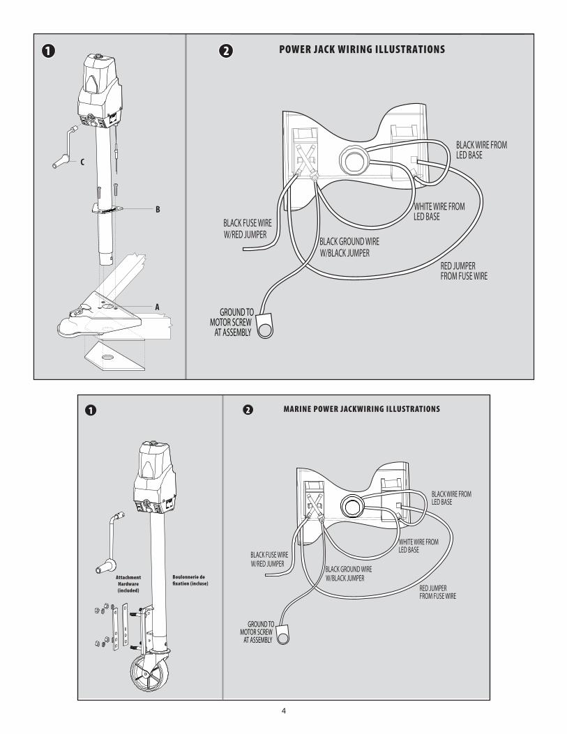
POWER JACK WIRING ILLUSTRATIONS
GROUND TOMOTOR SCREW
AT ASSEMBLY
BLACK FUSE WIREW/RED JUMPER
WHITE WIRE FROMLED BASE
RED JUMPERFROM FUSE WIRE
BLACK GROUND WIREW/BLACK JUMPER
BLACK WIRE FROMLED BASE
2
1 2 MARINE POWER JACKWIRING ILLUSTRATIONS
AttachmentHardware(included)
Boulonnerie de fixation (incluse)
GROUND TOMOTOR SCREW
AT ASSEMBLY
BLACK FUSE WIREW/RED JUMPER
WHITE WIRE FROMLED BASE
RED JUMPERFROM FUSE WIRE
BLACK GROUND WIREW/BLACK JUMPER
BLACK WIRE FROMLED BASE

5
•Installation •Fonctionnment •EntretienEntrée en vigueur : le 21 février 2014
NUMÉRO DE PIÈCE DU DOCUMENT : 88320
VÉRIN MOTORISÉ
Applications pour VR et marine
m MISE EN GARDEBLESSURES/DOMMAGES MATÉRIELS
• Rétracter complètement le vérin avant le remorquage.• Ne pas utiliser de blocs pour augmenter la hauteur du vérin.• Utiliser un vérin motorisé industriel de 1814 kg (4000 lb) si des barres stabilisatrices sont utilisées
entre la remorque et le véhicule servant de remorque et le véhicule servant au remorquage.
INSTALLATION1. Bloquer solidement les pneus de la remorque et le triangle d’attelage du
support.
2. Le vérin motorisé d’Atwood est conçu pour être fixé à la surfacesupérieure d’un triangle d’attelage à cadre en A, doté de trous demontage typiques des cadres en A d’Atwood (Figure 1). Utiliser lesinstructions d’installation du raccord (MPD 87984) si un raccordest installé. Le vérin motorisé pour bateau se fixe sur le côté d’uneremorque à triangle d’attelage droit.
3. Une plaque de support inférieur doit être utilisée pour le support latéraldu vérin pour véhicules de loisirs, sur la surface inférieure du cadre en A(Figure 1). DIAMÈTRES DU TROU : Léger - 5,1 cm (2,02 po) (MIN) 5,3 cm (2,09 po) (MAX)
De luxe/industriel - 5,58/2,20 5,79/2,28
Le trou de la plaque du support inférieur doit s’aligner avec celui du raccord. POUR COMMANDER UNE PLAQUE
DE SUPPORT PLUS BASSE : Léger - Atwood MPD 80263 De luxe/industriel - Atwood MPD 80570
Utiliser une soudure d’angle de 3 mm (1/8 po), une baguette de soudage E6011 AWS de 3 mm (1/8 po). L’intensité de l’appareil doit être de 160-180 A et 50 volts, souder la plaque sur toute la longueur, des deux côtés de la face inférieure du cadre en A. La hauteur maximale de cadre est de 15,2 cm (6 po).
4. Placer le vérin pour véhicule de loisir à travers les trous dans le raccordet abaisser la plaque de support (Figure 1-A). Fixer avec trois (3) boulons(3/8 po dia. x 5/8 po long de catégorie 5) (Figure 1-B). REMARQUE: Serrerles boulons à un couple minimal de 15 pi/lb et à un couple maximal de20 pi/lb. Remarque : Le vérin et le raccord doivent entrer en contact métal sur métal. Les trois boulons
de montage dotés de rondelles éventails doivent être utilisés. Les rondelles éventails sont conçues pour enlever la peinture sur la surface de la collerette du vérin. Les boulons doivent également enlever la peinture des trous de montage dans le raccord. Si un problème de mise à la masse se produit (aucune alimentation électrique), vérifier ces deux surfaces pour s’assurer qu’il y a bien un contact métal sur métal entre le vérin et le raccord. Pour le câblage, voir les SCHÉMAS DE CÂBLAGE des Figures 2 et 3.
5. Fixer le vérin comme il est illustré.6. Acheminer le fil à partir du moteur, le long du triangle d’attelage, jusqu’à
la batterie. Fixer solidement le fil au boîtier du vérin et au cadre de laremorque en utilisant des attaches de câble ou l’équivalent.
7. Enlever le fusible du porte-fusible. Brancher le fil du vérin directementsur la borne positive (+) de la batterie. Remettre le fusible dans leporte-fusible. Si une batterie auxiliaire est utilisée, connecter le fil à laborne positive (+) de la batterie auxiliaire, de sorte que le vérin puisseêtre utilisé lorsqu’il est connecté à une tension de 115 V. Si du filsupplémentaire est requis, utiliser un fil multibrin en cuivre torsadé no10 ou plus gros.
8. Après avoir réinstallé le fusible, vérifier l’installation en appuyant surl’interrupteur marqué « EXT » pour l’extension du vérin et « RET » pour larétraction du vérin.
9. Pour tous les vérins motorisés, vérifier le voyant de fonctionnement endéplaçant l’interrupteur de la position marche (ON) à la position arrêt(OFF).
10. Le vérin motorisé pourrait être livré emballé avec le pied Robofootd’Atwood. Les instructions d’installation, d’utilisation et d’entretiendu pied Robofoot d’Atwood sont incluses avec le Robofoot. Le piedRobofoot doit être installé après que le vérin a été fixé solidement auraccord.
m CAUTIONHAND OR FINGER INJURY
• Hold Robofoot below the clevis pin parts when installing. This is a moving part and is a potential pinch point.
SYMBOLES D’ALERTE DE SÉCURITÉSymboles de sécurité pour vous alerter contre des risques éventuels à votre sécurité personnelle.
Suivez tous les messages de sécurité qui accompagnent ces symboles.
m AVERTISSEMENTpour éviter des
blessures ou la mort
m MISE EN GARDEpour éviter des
blessures ou la mortPOUR VOTRE SÉCURITÉ, LIRE TOUTES LES INSTRUCTIONS AVANT
L’INSTALLATION ET L’UTILISATION
Installateur: remettre ces instructions au consommateur.Consommateur: conserver ces documents pour référence ultérieure.Le vérin motorisé d’Atwood est un vérin à vis motorisé de 12 V c.c. conçu pour uneutilisation sur des remorques de loisirs ou de bateau. Brevet no D349800. Le vérinest utilisé pour mettre la remorque à niveau et pour abaisser et soulever le raccordafin de le fixer au véhicule servant de remorque.
de luxe industriel marine
Capacité de levage max. (KG/lb) 1360/3000 1814/4000 453/1000
FONCTIONNEMENT 1. Pour élever ou abaisser le vérin, appuyer sur l’interrupteur marqué « EXT » ou «
RET ». Les termes « Étendre » et « Rétracter » se rapportent au vérin et non à la remorque.
2. Relâcher l’interrupteur lorsque le vérin s’approche de la rétraction ou de l’extension complète pour éviter une usure excessive de l’embrayage du moteur. a. Lorsque le vérin est complètement étendu ou rétracté ou atteint sa charge maximale, un déclic se fait entendre. C’est le déclic de l’embrayage du surpassement intégré au moteur pour prévenir une surcharge.Relâcher immédiatement l’interrupteur lorsque le déclic se fait entendre. Un vérin trop étendu ou trop rétracté risque de se courber. Si c’est le cas, utiliser la manette de surpassement manuel, en suivant l’étape 3 ci-dessous, pour effectuer le dégagement. b. La rétraction d’un vérin motorisé industriel peut générer un bruit dans la zone du frein. Ceci est normal et provient de la forte charge pour laquelle le vérin est conçu.
3. En cas de panne électrique, élever ou abaisser le vérin comme suit: FONCTIONNEMENT MANUEL POUR TOUS LES VÉRINS ÉCONOMIQUES ET DE PERFORMANCE a. Fixer l’adaptateur de manivelle, pièce no 85385, à une perceuse électrique. Une manivelle manuelle en option, pièce no 87891 (non incluse) (Figure 1-C), peut également être utilisée pour élever et abaisser manuellement le vérin. b. Insérer l’adaptateur de manivelle inclus dans le port d’accès de

6
Les guides sont seulement destinés à une utilisation avec les produits Atwood® par des techniciens de service qui ont réussi la formation d’Atwood®. Ce guide doit être utilisé en conjonction avec les instructions appropriées du manuel fourni avec le produit et conformément à toute norme industrielle. Ceci n’est pas une liste complète. Veuillez diriger vos questions concernant le service des produits Atwood® en composant le (866) 869-3118 avant de procéder.
CONDITIONS ET SOLUTIONS
L E M O T E U R N E F O N C T I O N N E P A STension faible ou inexistante .......................................Vérifier la batterie et les connexions électriques. La tension
minimale doit être de 10 V c.c.La collerette du vérin pourrait ne pas ..........................Nettoyer la peinture ou la saleté du point de contact du
entrer en contact suffisant avec cadre du raccord pour fournir une mise à la masse adéquate la surface du raccord pour sur la surface du raccordmise à la masse adéquate
Fusible grillé ................................................................Remplacer par un fusible AWG de 30 AFils lâches sur l’interrupteur de MARCHE/ARRÊT .........Resserrer les connexions du filInterrupteur de MARCHE/ARRÊT défectueux ...............Remplacer l’interrupteurMoteur défectueux ......................................................Remplacer le moteur
Vérin motoriséGUIDE DE DÉPANN AGE
m AVERTISSEMENTBLESSURES ET/OU DOMMAGE S MATÉRIE LS
• Si les problèmes suivants se manifestent, la remorque ne doit pas être utilisée avant que le problème n’ait été corrigé.
M A U V A I S E M I S E À L A T E R R Elorsque le bouton du vérin est enfoncé - Le vérin ne fonctionne pas .......................................... Inspecter le boulon de montage du moteur pour y repérer
du Loctite®. Si du Loctite® est présent, le remplacer par unenouvelle vis de 1/4-20 x 3 po et deux rondelles de blocage.Si aucun boulon n’est disponible, nettoyer le boulon actuelet le meuler avec une meule à polir. Inspecter le trou du boulon. Si le trou est sale, le nettoyer avec un taraud ¼-20.
L ’ E N G R E N A G E D U M O T E U R S ’ E M B R A Y ECeci est normal si le pied du vérin est complètement ..Aucune, mais relâcher l’interrupteur lorsque le bruit de
rétracté ou étendu l’embrayage est entenduVis sans fin usée ...........................................................Remplacer le piston du vérinLe tube intérieur du piston est sale .............................Nettoyer le tube du piston et le lubrifier en pulvérisant une
couche mince de siliconeLe piston intérieur est courbé ......................................Remplacer le piston intérieurL’embrayage est défectueux ........................................Remplacer le moteurLe vérin est à un angle ................................................Fixer solidement les boulons de montage et s’assurer
d’utiliser une plaque de support.Le triangle d’attelage a un poids excessif ....................Déterminer si le vérin convient au poids du triangle
d’attelage.
LE VOYANT DE FONCTIONNEMENT NE FONCTIONNE PASFils lâches sur l’interrupteur de MARCHE/ARRÊT .........Resserrer les connexions du filLa DEL de l’interrupteur ne s’allume pas .....................Remplacer la DEL
APPEL D’INTENSITÉPlage du moteur ..........................................................8 à 45 ampères
Le vérin s’abaisse et s’élèvepartiellement ou seulementpar intermittence
surpassement manuel pour engager la tige de surpassement manuel. c. Activer la perceuse ou faire tourner la manivelle (si la manivelle manuelle est utilisée) dans le sens horaire pour élever le vérin ou dans le sens antihoraire pour l’abaisser.
ENTRETIEN1. Avant chaque utilisation, inspecter les tubes du vérin et les remplacer s’ils sont
courbés ou endommagés.
2. Si du câblage est connecté à la borne de la batterie, l’inspecter au moins deux fois par année pour y détecter de la corrosion. Nettoyer avec une solution d’eau et de bicarbonate de soude et appliquer une fine couche de graisse. REMARQUE : Il faut également nettoyer les vis de mise à la masse du moteur (Figure 1-D) et les boulons de montage (Figure 1-B) en cas de problème de continuité de mise à la masse.
3. Une fois par année, étendre le vérin aussi loin que possible et nettoyer le tube du piston intérieur. Lubrifier le tube en pulvérisant une légère couche de lubrifiant à la silicone. Le système de pied de réception du moteur électrique est protégé par un fusible de 30 A. S’il doit être remplacé, utiliser uniquement un fusible AGC-30 de type Buss ou l’équivalent, disponible dans les magasins d’articles d’automobile.
4. Le pied Robofoot n’a pas besoin d’être lubrifié ou modifié après son installation.
Entrée en vigueur : le 21 février 2014
MISE EN GARDE IMPORTANTE – Si les barres stabilisatrices sont fixées au véhicule de remorquage et à la remorque pendant l’utilisation du vérin motorisé fixé à un triangle d’attelage, un embrayage pourrait survenir au moment où le vérin détecte la charge. Ceci se produit parce que le triangle d’attelage de la remorque et l’arrière du véhicule-remorqueursont soulevés. Les vérins de 1360 kg (3000 lb) ne peuvent pas soulever ce poids excessif. Dans cecas, il faut utiliser un vérin de 1814 kg (4000 lb). Le mécanisme de vis à bille utilisé dans ce vérinpeut permettre de soulever cette charge.

7
PIÈCES DE RECHANGEARTICLE 3K COURT 3K STANDARD 4K STANDARD MARINE DESCRIPTION
1 80938/9 80938/9 80938/9 80938/9 Couvercle supérieur (blanc/noir)
2 87057 87057 87057 87057 Vis du couvercle
3 87942 87942 87942 87942 Vis de mise à la masse du moteur
4 86111 86111 86111 86111 Rondelle de blocage
5 75625 75625 75625 75625 Moteur et bornes
6 87916 87916 87916 87916 Tube du couvercle
7 87108 87108 87108 87108 Trousse pour engrenage conique
8 88002 88002 88002 88002 Couvercle de boîte de vitesses
9 70298 70298 71132 70298 Goupille moletée à cartouche
10 87941 87941 87941 87941 Arbre d’entraînement
11 88058/63 88058/63 88058/63 88058/63 Couvercle inférieur
12 80909 80909 80909 80909 DEL*
13 87489 87500 87559 S/O Boîtier du vérin et ensemble dupiston, course 40,6 cm (16 po)
14 87847 87847 87847 87847 Support de rondelles
15 70667 70667 70667 70667 Tige
16 80992 80992 80992 80992 Faisceau de mise à la terre(non illustré)
17 87586 87586 87586 87586 Interrupteur de voyant
18 87570 87570 87570 87570 Interrupteur du moteur
19 87912 87912 87912 87912 Douille de réduction de tension
20 80993 80993 80993 80993 Cavalier et fusible
21 S/O S/O S/O S/O Fusibles
22 Optional Optional Optional Optional Manivelle
23 Optional Optional Optional Optional Goupille fendue
24 Optional Optional Optional Optional Pied rond
25 Optional Optional Optional Optional Axe d’épaulement
26 S/O S/O S/O S/O Écrou d’entraînement hexagonal (non illustré)
27 S/O S/O S/O S/O Fil de fusible
28 87150 Support
29 84037 Roulette
VÉRIN MOTORISÉ 3K ET 4K
1
29
28
VÉRIN MOTORISÉPOUR MARINE
2 3
4
5
8
1119
13
20
14
17
1218
9
10
6
7
sFusible AGC-30 A de type Buss

84
1
B
A
C
SCHÉMAS DE CÂBLAGE DU VÉRIN MOTORISÉ
VIS DE MASSE VERS LE MOTEUR
DE L’ENSEMBLE
FIL NOIR DU FUSIBLE AVEC CAVALIER ROUGE
FIL BLANC DE LA BASE DE LA DEL
CAVALIER ROUGE DU FIL DU FUSIBLE
FIL NOIR DE MISE À LA MASSE AVEC CAVALIER NOIR
FIL NOIR DE LA BASE DE LA DEL
2
1 2 SCHÉMAS DE CÂBLAGE DU VÉRIN POUR MARINE
Boulonnerie de fixation (incluse)
FIL NOIR DU FUSIBLE AVEC CAVALIER ROUGE
FIL BLANC DE LA BASE DE LA DEL
CAVALIER ROUGE DU FIL DU FUSIBLE
FIL NOIR DE MISE À LA MASSE AVEC CAVALIER NOIR
FIL NOIR DE LA BASE DE LA DEL
VIS DE MASSE VERS LE MOTEUR
DE L’ENSEMBLE

9
•Instalación •Operación •MantenimientoEfectivo: 2/21/14
DOCUMENTO DE PARTE NÚMERO 88320
GATO POTENTE
Aplicaciones RV y Marinas
m PRECAUCIÓNDAÑO PERSONAL/DAÑO DE LA PROPIEDAD
• Retirar el gato por completo antes de remolcar.• No utilice ladrillos para aumentar la altura del gato. • Utilice Heavy Duty Power Jack de 4000 libras si usted utiliza barras de ecualización entre el
remolque y el vehículo remolcador.
INSTALACIÓN1. Bloquear ruedas del remolque y apoyar firmemente la lanza del remolque.2. El Atwood RV Power Jack está diseñado para unirse a la punta de la
superficie de un tipo de lanza en forma de A (A-estructura) teniendo orificios de montaje típicos de acopladores Atwood en forma de A (A-estructura) figura 1. Usar instrucciones de instalación del acoplador (MPD 87984) si se instala el acoplador. El potente gato marítimo se une conel lado de una lanza directa del remolque.
3. Una placa inferior de soporte debe ser usada como soporte lateral del RVgato sobre la base inferior de A-estructura figura 1.
DIAMETROS DE AGUJEROS: Peso Liviano - 2.02˝ (MIN) 2.09˝ (MAX)
De lujo / Servicio Pesado - 2.20˝ 2.28˝ Agujero en el soporte de la placa inferior debe linearse con agujero en acoplador PARA PEDIR PLACA DE SOPORTE INFERIOR: Peso Liviano - Atwood MPD 80263
De lujo / Servicio Pesado - Atwood MPD 80570 Usando un 1/8˝ cordones de soldadura número E6011 AWS varilla de soldar 1/8˝ de diametro, máquina amplificadora (AC o DCRP) en 160-180 con 50 voltios, soldar placa longitud total en cada lado por debajo de la forma A (A-estructura). La altura máxima de la estructura es 6 pulgadas.
4. Colocar el RV gato a través de los agujeros en acoplador y placa de soporte inferior, figura 1-A. Fijar con tres (3) tornillos (3/8˝ diámetro x 5/8˝ largo, grado 5, (provistas) figura 1-B. NOTA: rotar tornillos a 15 pies libras como mínimo y 20 pies libras como máximo. Nota: Debe haber un metal para contacto metálico entre el gato y el acoplador. Los tres tornillos de anclajecon las arandelas de estrellas deben ser usados. Las arandelas de estrellas son diseñadas para remover pintura en la superficie del reborde del gato. Los tornillos además deberían remover pintura de los orificios de montaje en al acoplador. Si un problema con la conexión a tierra ocurre (por ejemplo: no hay energía), revisar estas dos superficies para asegurarse que hay un conexión de metal a metal entre el gato y el acoplador. Para instalación eléctrica (cableado), ver ilustraciones de cableado figura 2 y 3.
5. Unir gato como se muestra.6. Enviar el cable eléctrico desde el motor a lo largo de la lanza del remolque
a la batería. Asegurar los cables a la cubierta del gato y a la estructura del remolque usando precintos plásticos o algo equivalente.
7. Remover fusibles de la porta fusibles. Conectar el cable eléctrico desde el gato directamente al terminal positivo (+) de batería. Reemplazar el fusiblepor la porta fusibles. Para batería de auxilio, conectar el cable eléctrico al terminal positivo (+) de la batería de auxilio para que el gato pueda ser utilizado cuando se conecte a 115 v. Para cable adicional, usar cable de cobre trenzado numero 10 o más grande.
8. Después de reinstalar el fusible, revisar la instalación presionando la perilla marcada “EXT” para la extensión del gato o “RET” para retraer el gato.
9. En todos los gatos potentes revisar la luz de utilidad moviendo la perilla aencendido (ON) o apagado (OFF).
10. El Power Jack podría venir empaquetado con el Atwood Robofoot. Instrucciones para su instalación, funcionamiento y mantenimiento del Atwood Robofoot están incluidas con el Robofoot. El Robofoot debería serinstalado después de que el gato está firmemente unido al acoplador.
m PRECAUCIÓNHERIDA DE MANOS O DEDOS
• Sostener Robofoot debajo de las partes de la clavija de la abrazadera cuando se instala. Esta es una parte movible y es un punto potencial de pellizco.
SÍMBOLOS DE ADVERTENCIA DE SEGURIDADSímbolos de seguridad lo alertan de peligros potenciales personales.Obedecer todos los mensajes de seguridad siguiendo estos símbolos.
m ADVERTENCIAevite posible daño o muerte
mPRECAUCIÓNevite posible daño o muerte
POR SU SEGURIDAD LEA TODAS LAS INSTRUCCIONES ANTES DE LA INSTALACIÓN Y OPERACIÓN.
Instalador: Provea estas instrucciones al consumidor.Consumidor: Guarde estos documentos para referencia futura.
El Atwood Power Jack es un gato de motor de corriente continua de 12 voltios conducido por un gato mecánico con la intención de ser usado de manera recreativa y para remolques marítimos. Patente #D349800. El gato es usado para nivelar el remolque o levantar y bajar el acoplador para enganchar y remolcar el vehículo
de lujo servicio Pesado marítimo
Capacidad máxima de levantamiento libras 3000 4000 1000
FUNCIONAMIENTO1. Para levantar o bajar el gato presione el interruptor marcado como “EXT” o
“RET”. Extender y retraer en referencia al gato y no al remolque.2. Soltar el interruptor cuando el gato se acerque a la retracción completa o extensión
completa para prevenir el innecesario desgaste del embrague del motor. a. Cuando el gato alcance su apertura máxima o se retraiga su distancia o máxima carga un sonido será escuchado. Esto en la gran mayoría es el embragueconstruído dentro del motor para prevenir una sobrecarga. Soltar el interruptor inmediatamente cuando el sonido es escuchado. Si el gato ha sido estirado demasiado o retraído el mismo podría atascarse. Si esto sucede, operar con el mango de accionamiento manual, por PASO 3 abajo, para soltarlo del atasco. b. Cuando el gato potente de servicio pesado está siendo retraído, podría haber un sonido audible, proveniente del área de frenos. Esto es normal y es debido a lacarga alta por la cual este gato está calificado.
3. En caso de una falla eléctrica, levantar o bajar el gato de la siguiente manera:OPERACIÓN MANUAL PARA LOS GATOS POTENTES DE TODO VALOR Y RENDIMIENTO. a. Unir el Drill Crank adaptador parte #85385 a una taladradora eléctrica. Una palanca opcional de conducción manual parte #87891 (no incluida) (figura 1-C)puede además ser usada manualmente para levantar y bajar el gato. b. Insertar el Drill Crank Adapter dentro del puerto de acceso del control manualpara conectar la clavija de control manual. c. Activar taladro o rotar manija (en caso de usar la manija de conducción manual) mover en direccion a las agujas del reloj para levantar el gato y en sentido opuestoa las agujas del reloj para bajar el gato.
MANTENIMIENTO1. Antes de cada uso, revisar los tubos del gato y reemplazar los dañados o doblados. 2. Si los cables están conectados a la terminal de batería, revisar al menos dos
veces por año en caso de corrosión. Limpiar con una solución de bicarbonato y agua, y luego aplicar una delgada capa de lubricante. NOTA: El tornillo de la conexión a tierra
(figura 1-D) y los pernos de montaje (figura 1B) deben ser limpiados también si un problema de continuidad de la zona ocurre.
3. Una vez al año, extender el gato tan lejos como sea posible y limpiar el pistón interno del tubo. Cubrir el tubo con una capa fina de lubricante siliconado en spray . El motor electrico sistema pie de apoyo está protegido por un fusible de 30 amperios. Si un reemplazo es necesario, reemplazarlo solo con un fusible de tipo Buss AGC-30 o equivalente, disponible en tiendas de suministros automotores.
4. El Robofoot no necesita ser lubricado o modificado después de la instalación.

10
Las guías son solo destinadas a ser usadas para productos Atwood® por el servicio de técnicos quienes han exitosamente completado el entrenamiento Atwood®. Esta guía debe ser usada en conjunto con el apropiado manual de instrucciones proporcionado con el producto y cualquier industria estándar aplicable. Esto no intenta ser una lista completa. Por favor dirigir cualquier pregunta en cuanto al servicio de productos Atwood® al (866)869-3138 antes de continuar.
CONDICIONES CON SOLUCIONES
E L M O T O R N O F U N C I O N ASin o con bajo voltaje Revisar batería y conexiones eléctricas. Debe tener un minímo de
10 voltios de corriente continúa.Reborde de gato no hace buen .....................Limpiar pintura o suciedad del contacto de la estructura del
contacto para proveer acoplador para proveer una adecuada base con la superficie deladecuada conexión a acopladortierra con el acopladorde la superficie.
Fusible quemado ..........................................Reemplazarlo con fusible de 30 amperios de tipo AWGCables sueltos el interruptor ........................Asegurar las conexiones de cables
de encendido/apagado (ON/OFF)Fallas del interruptor de ...............................Reemplazar interruptor encendido/apagado (ON/OFF)Falla del motor .............................................Reemplazar motor
M A L A C O N E X I Ó N A T I E R R A cuando el botón está apretado sobre el gato - Jack doesn’t operate ................................................... Inspeccionar los pernos de anclaje del motor para Loctite®.
Si Loctite® está econtrado, reemplazarlo con nuevos tornillos 1/4-20 x 3” y dos arandelas de seguridad. Si los pernos no están disponibles, limpiar los actuales tornillos y el agujero con ruedas de alambre pulido. Inspeccionar el agujero de los pernos. Si el agujero de los pernos está sucio, limpiarlo con un 1/4-20 macho de roscar.
S E E N G A N C H A M O T O R D E E M B R A G U ENormal si el poste extensible esta ...............................Ninguno, pero soltar la perilla cuando escuche el embrague
retraído completamente o en posision extendida
Engranaje sin fin está desgastado ...............................Reemplazar pistón del gatoEl pistón interno está sucio Limpiar tubo de pistón y cubrir con capa liviana de aerosol
del silicónPistón interno está doblado ........................................Reemplazar pistón internoFalla embrague ...........................................................Reemplazar motorGato en ángulo Asegurar pernos de montaje y asegurar que un plato de
apoyo es usado.Peso excesivo de la lanza ............................................Determinar si el gato es adecuado para el peso de la lanza
L U Z D E U T I L I D A D N O F U N C I O N ACables sueltos en la perilla ..........................................Asegurar la conexión de cables de las perillasencendido/apagado (ON/OFF)LED no ilumina ............................................................Reemplazar LED
C O N S U M O D E A M P E R E SAlcance del motor .......................................................8-45 amperios
GATO POTENTEGUÍA DE SOLUCÍON DE PROBLEMAS
m ADVERTENCIADAÑOS PERSONALES Y/O DAÑOS DEL PRODUCTO
• Si cualquiera de las siguientes condiciones suceden, el remolque no debe ser usado hasta que la correcta acción sea llevada a cabo.
Efectivo: 2/21/14
PRECAUCIÓN IMPORTANTE - Si las barras del ecualizador están sujetas al vehículo remolcador (grúa) y al remolque mientras está funcionando la lanza del gato, usted podría sentir el embrague del motor en el momento que el gato acompaña la carga. Esto ocurrirá porque está levantando a ambos, la lanza del remolque y la parte trasera del vehículo remolcador. Los gatos potentes de 3000 libras no pueden levantar este excesivo peso. Para sobrellevar este peso excesivo, usted debería adquirir un gato potente de 4000 libras. El mecanismo de husillo a bola utilizado en este gato debería permitirle levantar esta carga.
El gato funciona solo parcialmente arriba o abajo o el gato funciona intermitentemente

11
SERVICIO PARTES REEMPLAZABLES
ARTÍCULO 3K CORTO 3K ESTÁNDAR
4K ESTÁNDAR MARINO DESCRIPCIÓN
1 80938/9 80938/9 80938/9 80938/9 Covertor Superior (Blanco/Negro)
2 87057 87057 87057 87057 Tornillo Del Covertor
3 87942 87942 87942 87942 Tornillo De Conexión A Tierra Del Motor
4 86111 86111 86111 86111 Arandela De Seguridad
5 75625 75625 75625 75625 Motor Y Terminales
6 87916 87916 87916 87916 Cubierta Del Tubo
7 87108 87108 87108 87108 Kit De Engranajes Cónicos
8 88002 88002 88002 88002 Covertor De Caja De Engranaje
9 70298 70298 71132 70298 Dedo De Arrastre
10 87941 87941 87941 87941 Eje De Transmisión
11 88058/63 88058/63 88058/63 88058/63 Covertor Parte Inferior
12 80909 80909 80909 80909 Luz* LED
13 87489 87500 87559 N/A Cubierta De Gato Y Montaje De Pistón Que Puede Moverse 16 Pulgadas
14 87847 87847 87847 87847 Arandelas Soporte
15 70667 70667 70667 70667 Tige / Clavija
16 80992 80992 80992 80992 Arnes De Conexión A Tierra (No Se Muestra)
17 87586 87586 87586 87586 Interruptor De Luz
18 87570 87570 87570 87570 Interruptor Del Motor
19 87912 87912 87912 87912 Casquillo De Reducción De Tensión Mecánica
20 80993 80993 80993 80993 Cable De Puente Y Fusible
21 N/A N/A N/A N/A Fusibles
22 Opcional Opcional Opcional Opcional Manija De Conducción Manual
23 Opcional Opcional Opcional Opcional Chaveta
24 Opcional Opcional Opcional Opcional Base Redonda
25 Opcional Opcional Opcional Opcional Clavija De La Abrazadera
26 N/A N/A N/A N/A Destornillador Hexagonal (No Se Muestra)
27 N/A N/A N/A N/A Cable Del Fusible
28 87150 Soporte
29 84037 Ruedita
3K Y 4K GATO POTENTE
1
29
28
GATO MARÍTIMO
2 3
4
5
8
1119
13
20
14
17
1218
9
10
6
7
SFusible De Tipo Buss Agc De 30 Amperios

12
1
B
A
C
POWER JACK WIRING ILLUSTRATIONS
GROUND TOMOTOR SCREW
AT ASSEMBLY
BLACK FUSE WIREW/RED JUMPER
WHITE WIRE FROMLED BASE
RED JUMPERFROM FUSE WIRE
BLACK GROUND WIREW/BLACK JUMPER
BLACK WIRE FROMLED BASE
2
1 2 MARINE POWER JACKWIRING ILLUSTRATIONS
AttachmentHardware(included)
Boulonnerie de fixation (incluse)
GROUND TOMOTOR SCREW
AT ASSEMBLY
BLACK FUSE WIREW/RED JUMPER
WHITE WIRE FROMLED BASE
RED JUMPERFROM FUSE WIRE
BLACK GROUND WIREW/BLACK JUMPER
BLACK WIRE FROMLED BASE
Herramientas Para Fijación
(Incluido)
ILUSTRACIONES DE LA INSTALACIÓN ELÉCTRICA DE GATO MARITIMO
CABLE NEGRO DE BASE LED
PUENTE ROJO DE CABLE FUSIBLE
ENSAMBLAJE DE CABLE FUSIBLE NEGRO CON CABLE PUENTE ROJO
LA CONEXIÓN A TIERRA AL TORNILLO DEL MOTOR EN
ENSAMBLAJE
CABLE NEGRO DE CONEXIÓN A TIERRA CON PUENTE NEGRO
CABLE BLANCO DE BASE LED
CABLE NEGRODE BASE LED
PUENTE ROJO DE CABLE FUSIBLE
ENSAMBLAJE DE CABLE FUSIBLE NEGRO
CON CABLE PUENTE ROJO
LA CONEXIÓN A TIERRA AL
TORNILLO DEL MOTOR EN
ENSAMBLAJE
CABLE NEGRO DE CONEXIÓN A TIERRA CON PUENTE NEGRO
CABLE BLANCO DE BASE LED