document no:ess-001 document title : engineering specification sheet for lalitpur … · ·...
TRANSCRIPT

DOCUMENT NO:ESS-001 DOCUMENT TITLE : ENGINEERING SPECIFICATION SHEET FOR LALITPUR 3 X 660 MW
Prepared : G.Aarthi Reviewed : C.Karunakaran Page 1 of 4
1.0 GENERAL
This Engineering Selection Sheet provides required Design and Performance Parameters for the LP Startup Condensate Pumps for Lalitpur Super Critical TPP (3x660 MW) situated in Uttar pradesh. This has to be read along with pump Technical Specification No:PC:TSP:LPSS: CON-PUMP:001
2.0 EQUIPMENT
2.1 The pumps covered by this specification are identified in the following table.(per boiler) QTY. DESCRIPTION TAG NOs.
Unit -1 Unit -2 Unit -3
1 CONDENSATE PUMP “A” CPA-01 CPA-02 CPA-03
1 CONDENSATE PUMP “B” CPB-01 CPB-02 CPB-03
3.0 DESIGN AND PERFORMANCE PARAMETERS
Name LP Startup Condensate Pump
Type Horizontal, Centrifugal, Double Suction
Location Out door
Tag Number(s) See section 2.1.
Number of Pumps Required per boiler Two (2)
Number of pumps per project Six (6)
Liquid to be Pumped Condensate Water
Specific Gravity 1.0
pH 8.5 – 9.6
Fluid Temperature Range 10 – 100 oC
Maximum Operating (Design Point) Temperature
100 oC
Design Fluid Temperature 135 oC
Design Maximum Supply Cooling Water Fluid Temperature (for Seal Cooling Heat Exchanger)
38oC
Design Maximum Supply Cooling Water Fluid Pressure (for Seal Cooling Heat Exchanger)
12 kg/cm2(g)
Rated Conditions – For Each Pump (Guarantee Case)
Design Flow rate, m³/hr 446
Design Total Developed Head, m Bidder to specify
DOCUMENT NO:ESS-001 DOCUMENT TITLE : ENGINEERING SPECIFICATION SHEET FOR LALITPUR 3 X 660 MW
Prepared : G.Aarthi Reviewed : C.Karunakaran Page 2 of 4
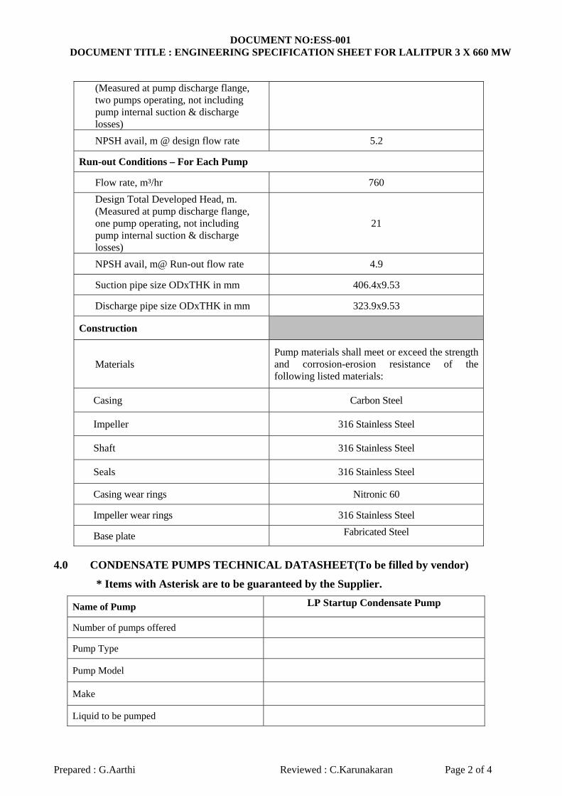
(Measured at pump discharge flange, two pumps operating, not including pump internal suction & discharge losses)
NPSH avail, m @ design flow rate 5.2
Run-out Conditions – For Each Pump
Flow rate, m³/hr 760
Design Total Developed Head, m. (Measured at pump discharge flange, one pump operating, not including pump internal suction & discharge losses)
21
NPSH avail, m@ Run-out flow rate 4.9
Suction pipe size ODxTHK in mm 406.4x9.53
Discharge pipe size ODxTHK in mm 323.9x9.53
Construction
Materials Pump materials shall meet or exceed the strength and corrosion-erosion resistance of the following listed materials:
Casing Carbon Steel
Impeller 316 Stainless Steel
Shaft 316 Stainless Steel
Seals 316 Stainless Steel
Casing wear rings Nitronic 60
Impeller wear rings 316 Stainless Steel
Base plate Fabricated Steel
4.0 CONDENSATE PUMPS TECHNICAL DATASHEET(To be filled by vendor)
* Items with Asterisk are to be guaranteed by the Supplier.
Name of Pump LP Startup Condensate Pump
Number of pumps offered
Pump Type
Pump Model
Make
Liquid to be pumped

DOCUMENT NO:ESS-001 DOCUMENT TITLE : ENGINEERING SPECIFICATION SHEET FOR LALITPUR 3 X 660 MW
Prepared : G.Aarthi Reviewed : C.Karunakaran Page 3 of 4
Specific gravity
PH
Service
Fluid Temperature, ºC
Capacity (m3/hr)
At Design Point *
Maximum Flow
Minimum Flow
At Runout Flow *
Total developed head (mlc)
At Design Point *
Maximum Flow
Minimum Flow
At Runout Flow *
NPSH required (mlc)
At Design Point *
Maximum Flow
Minimum Flow
At Runout Flow *
Number of Pump Stages
Pump speed (rpm) at Design Point
Pump speed (rpm) at Runout Flow
Pump Critical Speed (rpm)
Efficiency at Design Point (%) *
Motor Size (kW) *
Brake Horsepower Required (KW)
At Design Point
DOCUMENT NO:ESS-001 DOCUMENT TITLE : ENGINEERING SPECIFICATION SHEET FOR LALITPUR 3 X 660 MW
Prepared : G.Aarthi Reviewed : C.Karunakaran Page 4 of 4
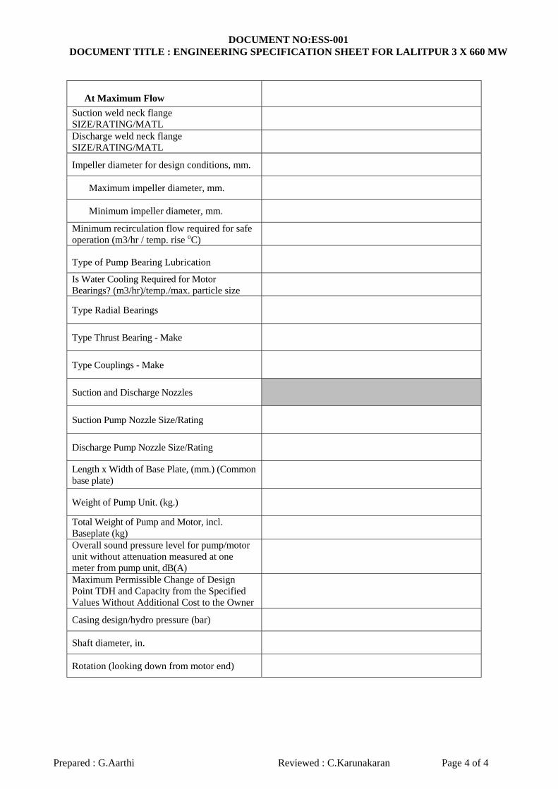
At Maximum Flow
Suction weld neck flange SIZE/RATING/MATL
Discharge weld neck flange SIZE/RATING/MATL
Impeller diameter for design conditions, mm.
Maximum impeller diameter, mm.
Minimum impeller diameter, mm.
Minimum recirculation flow required for safe operation (m3/hr / temp. rise oC)
Type of Pump Bearing Lubrication
Is Water Cooling Required for Motor Bearings? (m3/hr)/temp./max. particle size
Type Radial Bearings
Type Thrust Bearing - Make
Type Couplings - Make
Suction and Discharge Nozzles
Suction Pump Nozzle Size/Rating
Discharge Pump Nozzle Size/Rating
Length x Width of Base Plate, (mm.) (Common base plate)
Weight of Pump Unit. (kg.)
Total Weight of Pump and Motor, incl. Baseplate (kg)
Overall sound pressure level for pump/motor unit without attenuation measured at one meter from pump unit, dB(A)
Maximum Permissible Change of Design Point TDH and Capacity from the Specified Values Without Additional Cost to the Owner
Casing design/hydro pressure (bar)
Shaft diameter, in.
Rotation (looking down from motor end)

1
Bharat Heavy Electricals Ltd, Piping Centre, Chennai-600017
TITLE: TECHNICAL SPECIFICATION FOR CENTRIFUGAL PUMPS – CONDENSATE PUMP FOR LP START UP SYSTEM
REV: 00
PAGE: 1 OF 18
SPECIFICATION NO. PC:TSP:LPSS: CON-PUMP:001
CONTENTS
1.0 GENERAL
2.0 SCOPE OF SUPPLY
3.0 APPLICABLE CODES & STANDARDS
4.0 DESIGN REQUIREMENTS
5.0 EQUIPMENT REQUIREMENTS
6.0 DRAWING REQUIREMENTS
7.0 PAINTING AND SHIPPING REQUIREMENTS
8.0 EXCEPTIONS
APPENDIX A ENGINEERING SELECTION SHEET DOCUMENT NO.ESS-001 (PROJECT
SPECIFIC)
MOTOR DATA SHEET: PC: TSP: 81059 / Rev 02
PREPARED
REVIEWED APPROVED
M.R.Krishna C.Saravanan C.Karunakaran

2
Bharat Heavy Electricals Ltd, Piping Centre, Chennai-600017
TITLE: TECHNICAL SPECIFICATION FOR CENTRIFUGAL PUMPS – CONDENSATE PUMP FOR LP START UP SYSTEM
REV: 00
PAGE: 2 OF 18
SPECIFICATION NO. PC:TSP:LPSS: CON-PUMP:001
1.0 GENERAL 1.1 These specifications cover the design, engineering, performance, manufacturing and
testing requirements for complete 100% capacity, centrifugal, horizontal, double suction, pump assemblies with electric motors for the LP start up system condensate pumps.
1.1 The following terms used herein with initial capitalization, whether singular or plural
shall have the following defined meanings:
Customer / Project As specified in Purchase Document Purchaser BHEL Supplier To be selected by BHEL
1.2 The specification is intended to cover all of the work. Unless expressly excluded, any and
all equipment, labor, material and services not indicated therein but which may be necessary to complete any part of the work in a proper, substantial and workmanlike manner shall be furnished by the Seller without additional cost to the Purchaser. Any intended omission or exceptions to the requirements of this Specification are included in the “EXCEPTIONS TO THE SEPCIFICATIONS” sheet.
1.3 These specifications establish the requirements for the condensate pumps and appurtenances, as specified therein. The requirements of these specifications are the minimum for the equipment and are to be supplemented by the Supplier’s own requirements.
1.4 The Supplier shall comply with all of the requirements of these specifications. Approval
of any drawings and/or test results shall in no way relieve the Supplier from these responsibilities.
2.0 SCOPE OF SUPPLY
2.1 BY SUPPLIER 2.1.1 It is the intent to have the Supplier provides each pump and driver
mounted on a common base plate, designed for minimum field installation and assembly.
2.1.2 Equipment tag nos. for each pump / motor – As specified in data sheet
2.1.3 The equipment, material and services to be supplied by the Supplier shall consist of the following:

3
Bharat Heavy Electricals Ltd, Piping Centre, Chennai-600017
TITLE: TECHNICAL SPECIFICATION FOR CENTRIFUGAL PUMPS – CONDENSATE PUMP FOR LP START UP SYSTEM
REV: 00
PAGE: 3 OF 18
SPECIFICATION NO. PC:TSP:LPSS: CON-PUMP:001
a. The scope shall include each pump unit with all equipment, such
as motors, coupling with guard, mechanical seal, seal cooling plan, base plate companion flanges with fasteners, anchor bolts with fasteners and auxiliaries fully assembled and wired, requiring only connection to BHEL piping, electrical and control systems. Final alignment will be performed during pump installation.
b. All equipment shop tests as specified herein. c. Expedited schedules, drawings, procedures, pump and motor
curves, test reports and other documents and information specified herein.
d. List of commissioning/mandatory spare parts for the pumps, motors and accessories.
2.2 EXCLUSIONS
2.2.1 The following items are not covered a. Civil foundation b. Grouting for attaching the pump/driver common base plate to the
foundation c. Piping and accessories not specified herein. d. Erection/Installation of equipment e. Instruments and controls, unless otherwise specified herein. f. External electrical wiring and conduit. g. Motor starting equipment.
3.0 APPLICABLE CODES AND STANDARDS
3.1 The publications listed below form a part of these specifications as applicable.
This publication listing is intended to identify the codes and standards applicable to the design, fabrication and erection of the condensate pumps, but may not be all inclusive. The seller shall comply with all applicable codes and standards, whether or not identified in this listing. The text refers to these publications by the basic designation only. When specific requirements are stated in these specifications conflict with those required by codes and standards listed herein, the more stringent requirement, as interpreted by the Purchaser, shall govern. Such conflict shall be brought to the Purchaser’s attention in writing for disposition.
3.2 The design, materials, manufacturing, fabrication, inspection, testing and documentation of all equipment shall be in strict accordance with the latest
4
Bharat Heavy Electricals Ltd, Piping Centre, Chennai-600017
TITLE: TECHNICAL SPECIFICATION FOR CENTRIFUGAL PUMPS – CONDENSATE PUMP FOR LP START UP SYSTEM
REV: 00
PAGE: 4 OF 18
SPECIFICATION NO. PC:TSP:LPSS: CON-PUMP:001
edition and revision, in force as of the date of the purchase order, of the following codes and standards.
a. American National Standards Institute (ANSI) b. American Society for testing and materials (ASTM) c. American society of Mechanical Engineers (ASME) d. American Institute of Steel construction (AISC) e. American welding society (AWS) f. Anti friction bearing manufacturer’s Association (AFBMA) g. Heat exchanger institute (HEI) h. Hydraulic institute (ANSI/HI) i. International Building code (IBC) j. International Electro technical Commission (IEC) k. Instrument Society of America (ISA) l. Institute of Electrical and Electronics Engineers (IEEE) m. National Electric Code (NEC) n. National Electrical Manufacturers Association (NEMA) o. Steel Structure’s Painting Council (SSPC) p. Tubular Exchange Manufacturer’s Association (TEMA) q. Indian Standard IS5120, Technical requirements for Roto dynamic
special purpose pumps.
3.3 Additionally, the pumps shall comply with all currently applicable statutes, regulations and safety codes in the locality where the equipment will be installed.
3.4 The seller shall indicate the standards and codes to be used and shall list all differences.
3.5 All drawings and data sheets shall be in Metric units / SI units. All words shall be
in the English language.
4.0 DESIGN REQUIREMENTS
4.1 General 4.1.1 The condensate pumps will be used to transfer hot condensate water
from the Flash tank Drain tank (FTDT) to the main steam turbine condenser hotwell for reuse. Operation of the pumps will be intermittent, used during plant start up and shut down operations, and may be used on a more continuous basis during normal plant
5
Bharat Heavy Electricals Ltd, Piping Centre, Chennai-600017
TITLE: TECHNICAL SPECIFICATION FOR CENTRIFUGAL PUMPS – CONDENSATE PUMP FOR LP START UP SYSTEM
REV: 00
PAGE: 5 OF 18
SPECIFICATION NO. PC:TSP:LPSS: CON-PUMP:001
operations. In case of one pump failure, the other pump should have the capability to deliver the runout flow as indicated in the datasheet.
4.1.2 Each pump shall be designed for operation using the criteria
specified in Document no.ESS-001 “Engineering selection sheet for condensate pumps”.
4.1.3 The supplier/manufacturer’s standard methods of construction and
pump design for the requested service conditions shall be provided unless specifically excluded by these specifications.
4.2 Materials
4.2.1 Pump materials required are identified in Document no. ESS-001
“Engineering selection sheet for condensate pumps”.
4.2.2 Material options with pricing may be provided by the seller, along with an explanation of the material options advantages, disadvantages, costs and/or other benefits.
4.3 It is the intent to have the seller provides the pumps complete with drivers, with
each pump/motor combination mounted on a common base plate, designed for minimum field installation and assembly.
4.4 The equipment specified herein will be installed outdoors at the site located in
India. Design data for this facility is provided in Selection sheet no.ESS-001 “Site location information”.
4.5 Type &Arrangement
4.5.1 Each condensate pump shall be a 100% capacity, centrifugal, horizontal, double suction type pump.
4.5.2 The pumps will be arranged in parallel and will take suction from the
bottom of the flash tank drain tank.
4.5.3 The condensate pumps shall be “Identical” as defined b ANSI/HI standards for centrifugal pumps.
6
Bharat Heavy Electricals Ltd, Piping Centre, Chennai-600017
TITLE: TECHNICAL SPECIFICATION FOR CENTRIFUGAL PUMPS – CONDENSATE PUMP FOR LP START UP SYSTEM
REV: 00
PAGE: 6 OF 18
SPECIFICATION NO. PC:TSP:LPSS: CON-PUMP:001
4.6 Performance requirements 4.6.1 The performance requirements shall be as per Document no.ESS-001
“Engineering selection sheet for condensate pumps” 4.6.2 Each pump shall be designed to meet the following performance:
4.6.2.1 The net positive suction head required (NPSHR) shall be
lower than the net positive suction head available (NPSHA) and must be based on water at guarantee case conditions listed in document no. ESS-001 “Engineering selection sheet for condensate pumps”. Net positive suction head correction factors shall not be applied.
4.6.2.2 The pump shall be designed to ensure that there is adequate
margin between the NPSHR and the NPSHA for operation at run out conditions without pump cavitations at the pump run out condition.
4.6.2.3 The guarantee point total developed head listed in
“Document no. ESS-001 “Engineering selection sheet for condensate pumps” shall use the discharge connection centerline as the reference point. Head losses through the pump, including suction inlet losses and pump casing friction losses, are not included in the total developed head listed. Allowance for these losses shall be in addition to the NPSHA listed.
4.6.2.4 The pumps shall be selected and designed to use as much as
possible the seller’s standard production models for maximum interchangeability of parts between pumps and ease of maintenance and accessibility.
4.6.2.5 The pumps shall be designed for suitable outdoor locations.
4.6.2.6 The pump shall be suitable for direct connection to an
electric motor driver.
4.6.2.7 The wetted parts of the pump shall be suitable for the fluid handled by the pump (hot condensate).

7
Bharat Heavy Electricals Ltd, Piping Centre, Chennai-600017
TITLE: TECHNICAL SPECIFICATION FOR CENTRIFUGAL PUMPS – CONDENSATE PUMP FOR LP START UP SYSTEM
REV: 00
PAGE: 7 OF 18
SPECIFICATION NO. PC:TSP:LPSS: CON-PUMP:001
4.7 Operational requirements.
4.7.1 Two (2) or more pumps will be aligned / piped in parallel and will operate independently from each other.
4.7.2 The pumps shall be capable of operating satisfactorily at flows
ranging from minimum flow to the guarantee case design flow, and minimum flow to single pump operation maximum (run out) flow specified in document no. ESS-001 “Engineering selection sheet for condensate pumps”, without damage to the pumping equipment. The seller shall specify the minimum flow requirements in ESS-001.
4.7.3 The pumps shall be designed to pump condensate water ranging
from 10 Deg C to 108.3 Deg C without thermal stresses causing warping, buckling, misalignment, rubbing or other damaging effects.
4.7.4 Internal design clearances shall be adequate to account for pump
shaft deflection.
4.7.5 The pumps shall be designed for intermittent duty and shall be designed to accommodate the quantity of starts & stops as recommended by the ANSI / NEMA MG-1.
4.7.6 The pumps shall be designed to operate satisfactorily up to and
including 110% of design speed.
4.8 Pump characteristics
4.8.1 The pump shall be designed with a head capacity characteristic which rises steadily from pump maximum (run out) capacity to minimum flow. The pump head at shutoff shall be a minimum of 110% of the design head capacity.
4.8.2 The manufacturer shall indicate the specific speed of his design at the best efficiency point and the specific speed limitation as imposed by ANSI/HI.
4.8.3 Pump vibration shall not exceed the acceptable limits for centrifugal
pumps given by ANSI/HI at all discharge rates from minimum flow to pump maximum flow (run out). The maximum net positive
8
Bharat Heavy Electricals Ltd, Piping Centre, Chennai-600017
TITLE: TECHNICAL SPECIFICATION FOR CENTRIFUGAL PUMPS – CONDENSATE PUMP FOR LP START UP SYSTEM
REV: 00
PAGE: 8 OF 18
SPECIFICATION NO. PC:TSP:LPSS: CON-PUMP:001
suction head required by the pump shall be at least 1.0 meter less than the NPSH available at the design point.
4.8.4 The pumps shall operate without vapor binding or cavitation at all
operating conditions.
4.8.5 Each pump shall be capable of continuous operation at maximum flow (run out capacity), minimum flow and minimum NPSHA without sustaining mechanical damage.
4.9 Characteristic curves
4.9.1 The seller shall submit pump characteristic curves. Preliminary
pump characteristic curves shall be submitted with seller’s proposal. Curves shall indicate total head, efficiency, brake horsepower, and required net positive suction head, (basis 3% reduction in pump head) as ordinates, with capacity in cubic meters per hour as the abscissa. Final pump characteristic curves are required after award.
4.9.2 These curves shall be submitted for maximum and minimum impeller designs, which may be fitted to the pump casing and for the actual impeller design being provided.
4.9.3 The characteristic curves shall indicate pump performance from zero
capacity to the pump run out capacity during single pump operation and during two pump parallel operation while switching operation from one pump to the other.
4.9.4 Speed torque and motor performance curves shall also be submitted.
4.10 Testing
4.10.1 The seller shall perform a shop hydrostatic test and non cavitating performance test.
4.10.2 Additional inspection and testing requirements are defined in the
manufacturing quality plan provided separately
4.10.3 The pumps shall be tested in accordance with HI standards (Level A) and IS (Indian standard) 5120 at rated speed at the seller’s facility. Tests shall measure capacity, total head, efficiency and power. These tests shall form the basis for acceptance of the pumps except

9
Bharat Heavy Electricals Ltd, Piping Centre, Chennai-600017
TITLE: TECHNICAL SPECIFICATION FOR CENTRIFUGAL PUMPS – CONDENSATE PUMP FOR LP START UP SYSTEM
REV: 00
PAGE: 9 OF 18
SPECIFICATION NO. PC:TSP:LPSS: CON-PUMP:001
for vibration and noise. The pumps shall be tested over the range from shut off head to maximum flow. The duration of the test shall be minimum one (1) hour. A minimum of five (5) readings, approximately equidistant shall be taken for plotting the performance curves. Note: the negative tolerance on efficiency shall be limited to 2.5% and not 5% as indicated in Indian standard 5120.
4.10.4 The hydro test pressure on the casing shall be 1.5 times maximum
discharge head or twice the differential head, whichever is higher. Maximum discharge head is defined as the sum of the shutoff head and the maximum suction head. The duration of the test shall be minimum thirty (30) minutes.
4.10.5 In the event of leakage, the procedure for repairs shall be subject to review by the Purchaser. After the repair, the pump(s) shall be successfully hydrostatically re-tested at 1.5 times (minimum) the shut off discharge pressure.
4.10.6 The pump efficiency shall be calculated using the motor
manufacturer’s guaranteed efficiency. The test shall be made with the motor to be supplied to the customer for the actual pump.
4.10.7 If the shop performance tests indicate the tested pump fails to meet the guarantees stated herein, the other pump shall be shop tested in accordance with the stated requirements specified herein.
4.10.8 Any pump not meeting the guarantees shall receive all adjustments,
repairs, additions, or replacements as required at the seller’s expense for it to meet the guarantees.
4.10.9 Retesting and modifications will be repeated until all performance
guarantees are met or until arrangements are made which are acceptable to the purchaser. All additional testing will be done at the seller expense.
4.10.10 Certified test reports containing all test data, pump performance
curves and head capacity curves shall be submitted by the pump supplier to BHEL.
4.10.11 After the pumps/drivers have been installed at the site, they shall be
subjected to testing. If the site performance is found not to meet the

10
Bharat Heavy Electricals Ltd, Piping Centre, Chennai-600017
TITLE: TECHNICAL SPECIFICATION FOR CENTRIFUGAL PUMPS – CONDENSATE PUMP FOR LP START UP SYSTEM
REV: 00
PAGE: 10 OF 18
SPECIFICATION NO. PC:TSP:LPSS: CON-PUMP:001
requirements regarding vibration and noise as specified the equipment shall be rectified or replaced by the vendor at no extra cost to the purchaser.
4.11 Guarantees
4.11.1 The pumps shall be guaranteed to perform at the design point as
indicated in this specification and on the seller’s supplied performance curves and data sheets. The pumps shall be guaranteed to operate satisfactorily without pitting, cavitation, excessive vibration, or excessive noise.
4.11.2 The following parameters shall be guaranteed:
a. Capacity at the design point b. Total developed head at the design point. c. Pump speed at design point d. Pump efficiency at design point without negative tolerance e. Horsepower required at the design point f. Maximum shut off head at pump discharge flange g. No critical speed at or near pump operating speed. All critical
speeds shall be at least 25% greater than the highest operating speed.
h. A satisfactory test in accordance with the “testing” section of this specification.
5.0 EQUIPMENT REQUIREMENTS
5.1 Pump construction 5.1.1 A fabricated steel base plate shall be provided which is to be
installed on the customer’s concrete foundation. Each base plate shall support the pump and its drive assembly. Base plates shall be provided with a raised lip all around and shall have a threaded drain connection. Motor mounting provisions shall be acceptable to the motor manufacturer.
5.1.2 Base plates shall be designed to adequately support the equipment under all conditions and reaction forces. Equipment bases shall be designed to accept a connection to the plant grounding system.
5.1.3 Permanently installed lifting eyes or lugs shall be provided for each
pump and motor assembly to facilitate installation and maintenance.
11
Bharat Heavy Electricals Ltd, Piping Centre, Chennai-600017
TITLE: TECHNICAL SPECIFICATION FOR CENTRIFUGAL PUMPS – CONDENSATE PUMP FOR LP START UP SYSTEM
REV: 00
PAGE: 11 OF 18
SPECIFICATION NO. PC:TSP:LPSS: CON-PUMP:001
5.2 Shaft 5.2.1 The pump shaft shall be sized to transmit the power requirements of
the pump during all modes of operation without distortion or excessive vibration.
5.2.2 The shaft shall be ground and polished over its entire length.
5.2.3 The impeller shall be firmly keyed and secured to the shaft in proper
axial position. It shall be cast in one piece, accurately machined, finished all over and the water passages finished to the proper contour. The impellers shall be balanced in two planes to ISO Grade G6.3, as a minimum and comply with the vibration limits of the hydraulic institute. In addition to static balancing, impeller and balancing drum shall be balanced dynamically at or near operating speed.
5.2.4 Each shaft shall be designed so that no critical speed will occur within a 25 percent margin of the operating speed of the pump. It is preferred that the first critical speed of the pump shall occur above the pump operating speed.
5.3 Shaft couplings
5.3.1 The coupling shall be easily removed for equipment inspection or
maintenance.
5.3.2 Screwed, shrink, or press fits on the shafts are not acceptable coupling attachment configurations.
5.3.3 The shaft coupling shall be sized to transmit the maximum brake
horsepower requirements of the driven equipment with a service factor of not less than 2.
5.3.4 Shaft couplings shall be used between all drives and driven
equipment. Couplings shall be attached to driver and driven shafts by keys. Couplings shall be of the non lubricated, all metal (stainless steel) flexible disk type. Couplings for motors with ratings less than 250 hp shall have elastomeric elements.
5.4 Shaft sleeves and seals
12
Bharat Heavy Electricals Ltd, Piping Centre, Chennai-600017
TITLE: TECHNICAL SPECIFICATION FOR CENTRIFUGAL PUMPS – CONDENSATE PUMP FOR LP START UP SYSTEM
REV: 00
PAGE: 12 OF 18
SPECIFICATION NO. PC:TSP:LPSS: CON-PUMP:001
5.4.1 Pumps shall be furnished with removable shaft sleeves as required by system design. Where required, the shaft shall be completely protected and isolated from the pumped fluid by incorporating gasketed or similarly sealed joints between the sleeve and the shaft.
5.4.2 Access shall be provided for dismantling the drive shaft coupling and for maintenance and inspection of the pump seal. The coupling guard shall be the removable type.
5.4.3 All pumps shall be provided with mechanical shaft seals.
Mechanical shaft seals shall be of the john crane type or equivalent. Mechanical shaft seals shall be furnished with a complete flushing system, including interconnecting piping, isolation valves, strainer and orifice. The flushing system shall be (equal to or better than) an API flush plan best suited for the single seal system provided with the pump and utilize the pumped fluid unless otherwise required.
5.5 Casing
5.5.1 The pump casing, including suction connection shall be rated for the design conditions of the pumping system. Suction and discharge connections shall be raised faced flanged (ANSI Class 150). The casing shall be drilled and tapped for venting and draining and pressure connections with threaded plugs provided. Flange drilling shall comply with the provisions of ANSI B16.5.
5.5.2 The Pump supplier shall supply one companion suction flange and one companion discharge flange for each pump. Flanges shall be ASME Class 150, raised face, weld neck type.
5.5.3 Allowable loads on the pump nozzles shall be provided to BHEL.
The base plate shall be designed to accommodate these loads.
5.5.4 The pumps shall be provided with replaceable front and back wear rings for casings. Rings utilizing threads are unacceptable.
5.5.5 The pumps shall be supported between bearings with horizontally
split casings. The Pump supplier shall locate the suction and discharge nozzles in the lower half of the casing to permit rotor removal without disturbing the connected piping and shall supply heavy duty carbon steel casings.
13
Bharat Heavy Electricals Ltd, Piping Centre, Chennai-600017
TITLE: TECHNICAL SPECIFICATION FOR CENTRIFUGAL PUMPS – CONDENSATE PUMP FOR LP START UP SYSTEM
REV: 00
PAGE: 13 OF 18
SPECIFICATION NO. PC:TSP:LPSS: CON-PUMP:001
5.5.6 The corrosion allowance for all pump pressure parts shall be a minimum of 3 mm.
5.6 Bearings
5.6.1 Pump bearings shall be of the anti-friction type with regreasable type
bearing lubrication. Anti-friction bearings shall be designed for AFBMA L-10 life rating of not less than 40000 hrs at the design point. Pumps shall be provided with thrust bearings as required by the system designed to prevent thrust loads from being imposed on the drive motor bearings.
5.7 Pump accessories
5.7.1 Safety guards shall be provided for protection of personnel from all exposed moving and/or rotating machine elements. Each guard shall be fabricated from 20 gauge sheet steel and designed for easy installation and removal. Necessary supports and accessories shall be furnished with each guard. Safety guards for horizontal shafts, shaft couplings etc shall be an OSHA approved design.
5.7.2 Miscellaneous trim: All piping and valves required for seal or
stuffing box injection water, air vent valves, oil level indicators, grease lubricators and other miscellaneous accessories shall be furnished by the pump manufacturer. All wetted parts (valve, tubing etc) shall equal or exceed the corrosion characteristics of the casing materials.
5.7.3 All fasteners shall be of domestic origin.
5.8 Driver
5.8.1 Each pump shall be supplied with one electric motor each. The type
of electric motor shall be specified in the Technical data sheet 5.8.2 The rating of the pump driver shall be the larger of the following:
a. The maximum power required by the pump from zero discharge
to pump run out discharge at site climatic conditions.
b. 110% of the power required at the duty point at site climatic conditions.

14
Bharat Heavy Electricals Ltd, Piping Centre, Chennai-600017
TITLE: TECHNICAL SPECIFICATION FOR CENTRIFUGAL PUMPS – CONDENSATE PUMP FOR LP START UP SYSTEM
REV: 00
PAGE: 14 OF 18
SPECIFICATION NO. PC:TSP:LPSS: CON-PUMP:001
5.8.3 Electric motor drivers shall be furnished in accordance with BHEL motor requirements (see listing in Appendix A).
5.8.4 Normal supply conditions at the Power plant are 415V/3PH/50 Hz (3
wire solidly earthed). The thrust bearings shall be ball type. The total hydraulic thrust shall be incorporated in the thrust bearing design capacity.
5.8.5 Bearing lubricating system shall lubricate satisfactorily at 14.6 to
42.5 Deg ambient site temperature range.
5.8.6 Electric motors shall be selected so that their rating will not be exceeded by the brake horsepower of the pump over its entire operating range.
5.8.7 Pump supplier shall complete the Motor data sheet in BHEL format
and also indicate rated current, locked rotor current and space heater power.
5.9 Welding
5.9.1 The welding of pumps shall be in accordance with the Pump
manufacturer’s weld procedures.
5.9.2 Permitted welding processes shall be as specified in the ASME codes referenced herein and shall include the restrictions and limitations applicable to those processes as specified.
5.9.3 Preheat and inter pass temperature shall be performed in accordance
with the WPS for dynamic components.
5.9.4 The minimum preheat temperature and maximum inter pass temperature shall be specified in the WPS.
5.9.5 When weld joint details are specified by the design documents, they
shall be prepared in accordance with the design documents.
5.9.6 Required NDE of welds or components shall be performed in
accordance with the Manufacturer’s Quality Plan.

15
Bharat Heavy Electricals Ltd, Piping Centre, Chennai-600017
TITLE: TECHNICAL SPECIFICATION FOR CENTRIFUGAL PUMPS – CONDENSATE PUMP FOR LP START UP SYSTEM
REV: 00
PAGE: 15 OF 18
SPECIFICATION NO. PC:TSP:LPSS: CON-PUMP:001
5.9.6.1 Visual examination of welds may begin immediately after the completed welds have cooled to near ambient temperature. However magnetic particle, liquid penetrant and ultrasonic examinations shall be performed no less than 48 hrs after completion of the welds on quenched and tempered steels (i.e. ASTM A514 and A517)
5.10 Base plate 5.10.1 Pump supplier shall provide a common fabricated steel base plate for
the pumps and drivers.
5.10.2 Base plate shall be sufficiently rigid to allow shipment with the driver, mounted without the occurrence of any distortion to the base plate.
5.10.3 Base plates shall be fabricated steel with integral drip lip or drip pan
and threaded drain connection and shall be designed to provide common support and maintain proper alignment of the pump and the motor.
5.11 Noise level and vibration
5.11.1 Pumps shall run smooth without noise and vibration. Noise level produced individually or collectively (pump and motor) shall not exceed 85 dB (A) measured at a distance of 1.5 meters from the outline of equipment source in any direction.
5.11.2 The overall vibration level shall be as per hydraulic institute
standards. 5.12 Marking
5.12.1 A permanently attached corrosion resistant nameplate shall be
affixed at a prominent location on the outside of each condensate pump and shall include the following information as a minimum. a. Name of supplier/manufacturer
b. Equipment description (i.e. condensate pump) size, model
number and serial number.
c. Supplier’s shop order number

16
Bharat Heavy Electricals Ltd, Piping Centre, Chennai-600017
TITLE: TECHNICAL SPECIFICATION FOR CENTRIFUGAL PUMPS – CONDENSATE PUMP FOR LP START UP SYSTEM
REV: 00
PAGE: 16 OF 18
SPECIFICATION NO. PC:TSP:LPSS: CON-PUMP:001
d. BHEL’s purchase order number
e. Work order number
f. Conditions of service including service fluid pump capacity, total head, minimum NPSH required, temperature, specific gravity, efficiency, brake horsepower and speed.
5.12.2 A rotation arrow shall be permanently attached in a readily visible area on the motor mounting bracket.
5.12.3 Component parts shall be clearly marked to assure proper assembly in the field.
5.12.4 Nameplates mounted on equipment shall be attached with stainless
steel pinhead screws, rivets, drive screws or epoxy glue.
5.12.5 Name plates shall be 1/16” to 1.8” (2 mm to 4 mm) thick. The size of nameplates shall be a minimum of ¾” by 3 inches and include the tag numbers above. The text shall be sized as large as possible with size constraints.
5.13 Spare parts
5.13.1 The Pump supplier shall submit a list of all recommended spare parts. The list is to be based on requirements for normal continuous operation of the pumps and motors as specified in these specifications.
5.13.2 The Pump supplier shall submit a recommended spare parts list with
prices for both a three (3) and a five (5) year interval. Spare parts list shall indicate a summary of the criticality of the various parts relative to the expected life of the part before failure based on the supplier’s experience. Spare parts list shall contain all drawing reference numbers, item numbers, part numbers, a/or catalog numbers necessary to identify spare parts.
5.13.3 The pump supplier shall quote price separately for mandatory spares
list (if applicable).

17
Bharat Heavy Electricals Ltd, Piping Centre, Chennai-600017
TITLE: TECHNICAL SPECIFICATION FOR CENTRIFUGAL PUMPS – CONDENSATE PUMP FOR LP START UP SYSTEM
REV: 00
PAGE: 17 OF 18
SPECIFICATION NO. PC:TSP:LPSS: CON-PUMP:001
6.0 DRAWING REQUIREMENTS
6.1 General
6.1.1 Fabrication of pumps shall be based on BHEL’s approval on drawings.
6.1.2 Submitted documents shall reference to BHEL P.O Number.
6.1.3 Any drawings which reflect in attention to or noncompliance with
specification requirements, lacks certification for the specific project or which is unchecked will be rejected by BHEL for proper compliance, completion and/or checking.
6.1.4 Additional detailed drawings, where required for approval by BHEL
shall show all information necessary to assure complete knowledge of the equipment and/or installation.
6.1.5 All drawings, data and documents submitted by the supplier shall be in the English language system and metric units.
6.2 Documents to be submitted after P.O 6.2.1 Schedule of drawings and documents to be submitted for review,
approval and information with submission dates.
6.2.2 Quality Assurance Plan (QAP)
6.2.3 Detailed general arrangement drawing of pump and driver. This drawing shall indicate all the design data and information furnished in the document no. ESS-001 Data sheets.
6.2.4 Pump and driver with static and dynamic loads, details of fixing,
grouting and all base plate anchor bolt hole locations.
6.2.5 Cross section drawing of the pump with complete part list, materials of construction and relevant standards for each part.
6.2.6 Pump performance curves flow rate versus head, break kilowatts,
efficiency, NPSHR from zero flow to maximum flow and torque-speed curve.
18
Bharat Heavy Electricals Ltd, Piping Centre, Chennai-600017
TITLE: TECHNICAL SPECIFICATION FOR CENTRIFUGAL PUMPS – CONDENSATE PUMP FOR LP START UP SYSTEM
REV: 00
PAGE: 18 OF 18
SPECIFICATION NO. PC:TSP:LPSS: CON-PUMP:001
6.2.7 Scheme for pump sealing, lubrication and cooling. 6.2.8 Driver dimensional drawing.
6.2.9 Surface preparation and painting procedure.
6.2.10 Catalogues, data sheets and drawings for instruments.
6.2.11 Installation, operations and maintenance manual along with
lubrication schedule. 7.0 PAINTING AND SHIPPING REQUIREMENTS
7.1 Painting and coatings shall be as per QP.
8.0 EXCEPTIONS
8.1 Offer shall be submitted along with “EXCEPTIONS TO THE
SPECIFICATION” (Clause wise)
8.2 If there is no section with the header “Exceptions / Deviations to the specification” enclosed along with the technical officer, it is interpreted that the offer is strictly in accordance with the specification without any deviation.
8.3 Any exception / deviation listed and agreed by the purchaser shall become agreed
modification to the specification for that particular contract.

DOCUMENT NO:ESS-002 DOCUMENT TITLE : ENGINEERING SPECIFICATION SHEET FOR MOUDA(2 X 660 MW)
Prepared : E.Krithiga Approved:G.Aarthi Reviewed : C.Karunakaran Page 1 of 4
1.0 GENERAL
This Engineering Selection Sheet provides required Design and Performance Parameters for the LP Startup Condensate Pumps for Mouda Super Critical TPP (2x660 MW) situated in Mouda Tehsil, Nagpur district, Maharashtra state. This has to be read along with pump Technical Specification No: PC: TSP: LPSS: CON-PUMP: 002
2.0 EQUIPMENT 2.1 The pumps covered by this specification are identified in the following table.(per boiler)
QTY. DESCRIPTION TAG NOS.
Unit-1 Unit-2 1 CONDENSATE PUMP “A” 30LCL30AP001 40LCL30AP001 1 CONDENSATE PUMP “B” 30LCL30AP002 40LCL30AP002
3.0 DESIGN AND PERFORMANCE PARAMETERS
Name LP Startup Condensate Pump
Type Horizontal, Centrifugal, Double Suction
Location Out door
Tag Number(s) See section 2.1.
Number of Pumps Required per boiler Two (2)
Number of pumps per project Four (4)
Liquid to be Pumped Condensate Water
Specific Gravity 0.959
pH 6.8 – 7.2
Fluid Temperature Range 15 – 100 oC Maximum Operating (Design Point) Temperature 100 oC
Design Fluid Temperature 135 oC Design Maximum Supply Cooling Water Fluid Temperature (for Seal Cooling Heat Exchanger)
38oC
Design Maximum Supply Cooling Water Fluid Pressure (for Seal Cooling Heat Exchanger)
12 kg/cm2(g)
Rated Conditions – For each pump (Guarantee Case)
Design Flow rate, m³/hr 500 Design Total Developed Head, m (Measured at pump discharge flange, two pumps operating, not including pump internal suction & discharge losses)
Bidder to Specify
DOCUMENT NO:ESS-002 DOCUMENT TITLE : ENGINEERING SPECIFICATION SHEET FOR MOUDA(2 X 660 MW)
Prepared : E.Krithiga Approved:G.Aarthi Reviewed : C.Karunakaran Page 2 of 4
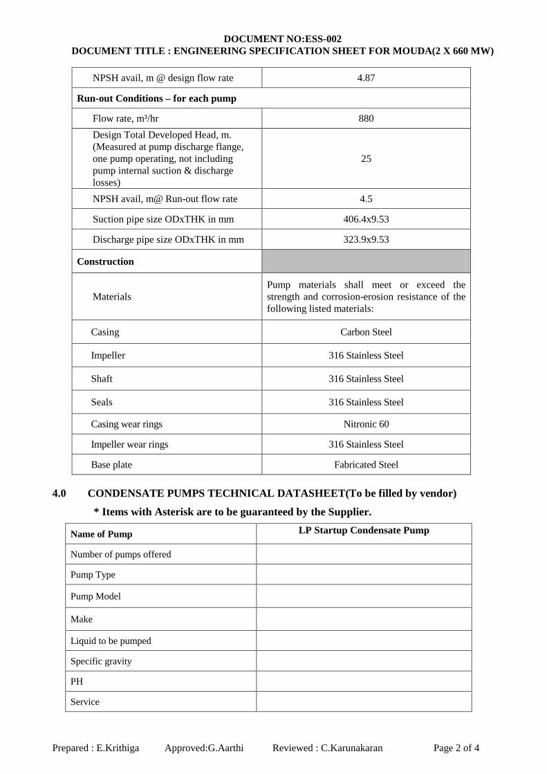
NPSH avail, m @ design flow rate 4.87
Run-out Conditions – for each pump
Flow rate, m³/hr 880 Design Total Developed Head, m. (Measured at pump discharge flange, one pump operating, not including pump internal suction & discharge losses)
25
NPSH avail, m@ Run-out flow rate 4.5
Suction pipe size ODxTHK in mm 406.4x9.53
Discharge pipe size ODxTHK in mm 323.9x9.53
Construction
Materials Pump materials shall meet or exceed the strength and corrosion-erosion resistance of the following listed materials:
Casing Carbon Steel
Impeller 316 Stainless Steel
Shaft 316 Stainless Steel
Seals 316 Stainless Steel
Casing wear rings Nitronic 60
Impeller wear rings 316 Stainless Steel
Base plate Fabricated Steel 4.0 CONDENSATE PUMPS TECHNICAL DATASHEET(To be filled by vendor)
* Items with Asterisk are to be guaranteed by the Supplier.
Name of Pump LP Startup Condensate Pump
Number of pumps offered
Pump Type
Pump Model
Make
Liquid to be pumped
Specific gravity
PH
Service

DOCUMENT NO:ESS-002 DOCUMENT TITLE : ENGINEERING SPECIFICATION SHEET FOR MOUDA(2 X 660 MW)
Prepared : E.Krithiga Approved:G.Aarthi Reviewed : C.Karunakaran Page 3 of 4
Fluid Temperature, ºC
Capacity (m3/hr)
At Design Point *
Maximum Flow
Minimum Flow
At Runout Flow *
Total developed head (mlc)
At Design Point *
Maximum Flow
Minimum Flow
At Runout Flow *
NPSH required (mlc)
At Design Point *
Maximum Flow
Minimum Flow
At Runout Flow *
Number of Pump Stages
Pump speed (rpm) at Design Point
Pump speed (rpm) at Runout Flow
Pump Critical Speed (rpm)
Efficiency at Design Point (%) *
Motor Size (kW) *
Brake Horsepower Required (KW)
At Design Point
At Maximum Flow
Suction weld neck flange SIZE/RATING/MATL
Discharge weld neck flange SIZE/RATING/MATL
DOCUMENT NO:ESS-002 DOCUMENT TITLE : ENGINEERING SPECIFICATION SHEET FOR MOUDA(2 X 660 MW)
Prepared : E.Krithiga Approved:G.Aarthi Reviewed : C.Karunakaran Page 4 of 4
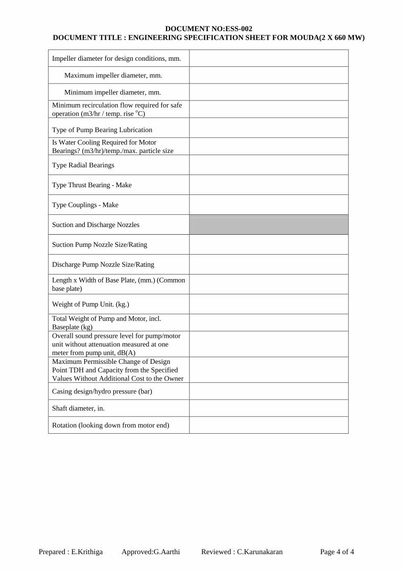
Impeller diameter for design conditions, mm.
Maximum impeller diameter, mm.
Minimum impeller diameter, mm.
Minimum recirculation flow required for safe operation (m3/hr / temp. rise o C)
Type of Pump Bearing Lubrication
Is Water Cooling Required for Motor Bearings? (m3/hr)/temp./max. particle size
Type Radial Bearings
Type Thrust Bearing - Make
Type Couplings - Make
Suction and Discharge Nozzles
Suction Pump Nozzle Size/Rating
Discharge Pump Nozzle Size/Rating
Length x Width of Base Plate, (mm.) (Common base plate)
Weight of Pump Unit. (kg.)
Total Weight of Pump and Motor, incl. Baseplate (kg)
Overall sound pressure level for pump/motor unit without attenuation measured at one meter from pump unit, dB(A)
Maximum Permissible Change of Design Point TDH and Capacity from the Specified Values Without Additional Cost to the Owner
Casing design/hydro pressure (bar)
Shaft diameter, in.
Rotation (looking down from motor end)
1
Bharat Heavy Electricals Ltd, Piping Centre, Chennai-600017
TITLE: TECHNICAL SPECIFICATION FOR CENTRIFUGAL PUMPS – CONDENSATE PUMP FOR LP START UP SYSTEM
REV: 00
PAGE 1 OF 20
SPECIFICATION NO. PC:TSP:LPSS: CON-PUMP:002
CONTENTS
1.0 GENERAL 2.0 SCOPE OF SUPPLY 3.0 APPLICABLE CODES & STANDARDS 4.0 DESIGN REQUIREMENTS 5.0 EQUIPMENT REQUIREMENTS 6.0 DRAWING REQUIREMENTS 7.0 PAINTING AND SHIPPING REQUIREMENTS 8.0 EXCEPTIONS APPENDIX A ENGINEERING SELECTION SHEET DOCUMENT NO.ESS-002 (PROJECT
SPECIFIC) MOTOR DATA SHEET PC: TSP: 81059 / Rev 02
PREPARED
REVIEWED APPROVED
M.R.Krishna M.Manoharan C.Karunakaran

2
Bharat Heavy Electricals Ltd, Piping Centre, Chennai-600017
TITLE: TECHNICAL SPECIFICATION FOR CENTRIFUGAL PUMPS – CONDENSATE PUMP FOR LP START UP SYSTEM
REV: 00
PAGE 2 OF 20
SPECIFICATION NO. PC:TSP:LPSS: CON-PUMP:002
1.0 GENERAL 1.1 These specifications cover the design, engineering, performance, manufacturing and
testing requirements for complete 100% capacity, centrifugal, horizontal, double suction, pump assemblies with electric motors for the LP start up system condensate pumps.
1.1 The following terms used herein with initial capitalization, whether singular or plural
shall have the following defined meanings:
Customer / Project As specified in Purchase Document Purchaser BHEL Supplier To be selected by BHEL
1.2 The specification is intended to cover all of the work. Unless expressly excluded, any and
all equipment, labor, material and services not indicated therein but which may be necessary to complete any part of the work in a proper, substantial and workmanlike manner shall be furnished by the Seller without additional cost to the Purchaser. Any intended omission or exceptions to the requirements of this Specification are included in the “EXCEPTIONS TO THE SEPCIFICATIONS” sheet.
1.3 These specifications establish the requirements for the condensate pumps and appurtenances, as specified therein. The requirements of these specifications are the minimum for the equipment and are to be supplemented by the Supplier’s own requirements.
1.4 The Supplier shall comply with all of the requirements of these specifications. Approval
of any drawings and/or test results shall in no way relieve the Supplier from these responsibilities.
1.5 All documents, drawings and attachments shall be submitted to the Purchaser using SI-Metric Units and the English language.
2.0 SCOPE OF SUPPLY
2.1 BY SUPPLIER 2.1.1 It is the intent to have the Supplier provides each pump and driver
mounted on a common base plate, designed for minimum field installation and assembly.

3
Bharat Heavy Electricals Ltd, Piping Centre, Chennai-600017
TITLE: TECHNICAL SPECIFICATION FOR CENTRIFUGAL PUMPS – CONDENSATE PUMP FOR LP START UP SYSTEM
REV: 00
PAGE 3 OF 20
SPECIFICATION NO. PC:TSP:LPSS: CON-PUMP:002
2.1.2 Equipment tag nos. for each pump / motor – As specified in data sheet
2.1.3 The equipment, material and services to be supplied by the Supplier shall consist of the following:
a. The scope shall include each pump unit with all equipment, such
as motors, coupling with guard, mechanical seal, seal cooling plan, base plate companion flanges with fasteners, anchor bolts with fasteners and auxiliaries fully assembled and wired, requiring only connection to BHEL piping, electrical and control systems. Final alignment will be performed during pump installation.
b. All equipment shop tests as specified herein. c. Expedited schedules, drawings, procedures, pump and motor
curves, test reports and other documents and information specified herein.
d. List of commissioning/mandatory spare parts for the pumps, motors and accessories.
e. Insulation-if required to meet noise requirements. f. One lot of any (unused) special tools required for installation and
maintenance, if required.
2.2 EXCLUSIONS
The following items are not covered a. Civil foundation b. Grouting for attaching the pump/driver common base plate to the
foundation c. Piping and accessories not specified herein. d. Erection/Installation of equipment e. Instruments and controls, unless otherwise specified herein. f. External electrical wiring and conduit. g. Motor starting equipment.
3.0 APPLICABLE CODES AND STANDARDS
3.1 The publications listed below form a part of these specifications as applicable.
This publication listing is intended to identify the codes and standards applicable to the design, fabrication and erection of the condensate pumps, but may not be all inclusive. The seller shall comply with all applicable codes and standards, whether or not identified in this listing. The text refers to these publications by the basic designation only. When specific requirements are stated in these

4
Bharat Heavy Electricals Ltd, Piping Centre, Chennai-600017
TITLE: TECHNICAL SPECIFICATION FOR CENTRIFUGAL PUMPS – CONDENSATE PUMP FOR LP START UP SYSTEM
REV: 00
PAGE 4 OF 20
SPECIFICATION NO. PC:TSP:LPSS: CON-PUMP:002
specifications conflict with those required by codes and standards listed herein, the more stringent requirement, as interpreted by the Purchaser, shall govern. Such conflict shall be brought to the Purchaser’s attention in writing for disposition.
3.2 The design, materials, manufacturing, fabrication, inspection, testing and documentation of all equipment shall be in strict accordance with the latest edition and revision, in force as of the date of the purchase order, of the following codes and standards.
a. American National Standards Institute (ANSI) b. American Society for testing and materials (ASTM) c. American society of Mechanical Engineers (ASME) d. American Institute of Steel construction (AISC) e. American welding society (AWS) f. Anti friction bearing manufacturer’s Association (AFBMA) g. Heat exchanger institute (HEI) h. Hydraulic institute (ANSI/HI) i. International Building code (IBC) j. International Electro technical Commission (IEC) k. Instrument Society of America (ISA) l. Institute of Electrical and Electronics Engineers (IEEE) m. National Electric Code (NEC) n. National Electrical Manufacturers Association (NEMA) o. Steel Structure’s Painting Council (SSPC) p. Tubular Exchange Manufacturer’s Association (TEMA) q. Indian Standard IS5120, Technical requirements for Roto dynamic
special purpose pumps.
3.3 Additionally, the pumps shall comply with all currently applicable statutes, regulations and safety codes in the locality where the equipment will be installed.
3.4 The seller shall indicate the standards and codes to be used and shall list all differences.
3.5 All drawings and data sheets shall be in Metric units / SI units. All words shall be
in the English language.

5
Bharat Heavy Electricals Ltd, Piping Centre, Chennai-600017
TITLE: TECHNICAL SPECIFICATION FOR CENTRIFUGAL PUMPS – CONDENSATE PUMP FOR LP START UP SYSTEM
REV: 00
PAGE 5 OF 20
SPECIFICATION NO. PC:TSP:LPSS: CON-PUMP:002
4.0 DESIGN REQUIREMENTS
4.1 General 4.1.1 The condensate pumps will be used to transfer hot condensate water
from the Flash tank Drain tank (FTDT) to the main steam turbine condenser hotwell for reuse. Operation of the pumps will be intermittent, used during plant start up and shut down operations, and may be used on a more continuous basis during normal plant operations. In case of one pump failure, the other pump should have the capability to deliver the runout flow as indicated in the datasheet.
4.1.2 Each pump shall be designed for operation using the criteria specified in Document no.ESS-002 “Engineering selection sheet for condensate pumps”.
4.1.3 The supplier/manufacturer’s standard methods of construction and
pump design for the requested service conditions shall be provided unless specifically excluded by these specifications.
4.2 Materials
4.2.1 Pump materials required are identified in Document no. ESS-002
“Engineering selection sheet for condensate pumps”.
4.2.2 Material options with pricing may be provided by the seller, along with an explanation of the material options advantages, disadvantages, costs and/or other benefits.
4.3 It is the intent to have the seller provides the pumps complete with drivers, with
each pump/motor combination mounted on a common base plate, designed for minimum field installation and assembly.
4.4 The equipment specified herein will be installed outdoors at the site located in
India. Design data for this facility is provided in Selection sheet no.ESS-002 “Site location information”.
4.5 Type &Arrangement

6
Bharat Heavy Electricals Ltd, Piping Centre, Chennai-600017
TITLE: TECHNICAL SPECIFICATION FOR CENTRIFUGAL PUMPS – CONDENSATE PUMP FOR LP START UP SYSTEM
REV: 00
PAGE 6 OF 20
SPECIFICATION NO. PC:TSP:LPSS: CON-PUMP:002
4.5.1 Each condensate pump shall be a 100% capacity, centrifugal, horizontal, double suction type pump.
4.5.2 The pumps will be arranged in parallel and will take suction from the
bottom of the flash tank drain tank.
4.5.3 The condensate pumps shall be “Identical” as defined by ANSI/HI standards for centrifugal pumps.
4.5.4 Assembly and dismantling of each pump with the drive motor shall
be possible without disturbing the grouting base plate or alignment.
4.6 Performance requirements 4.6.1 The performance requirements shall be as per Document no.ESS-002
“Engineering selection sheet for condensate pumps” 4.6.2 Each pump shall be designed to meet the following performance:
4.6.2.1 The net positive suction head required (NPSHR) shall be
lower than the net positive suction head available (NPSHA
) and must be based on water at guarantee case conditions listed in document no. ESS-002 “Engineering selection sheet for condensate pumps”. Net positive suction head correction factors shall not be applied.
4.6.2.2 The pump shall be designed to ensure that there is adequate margin between the NPSHR and the NPSHA
for operation at run out conditions without pump cavitations at the pump run out condition.
4.6.2.3 The guarantee point total developed head listed in “Document no. ESS-002 “Engineering selection sheet for condensate pumps” shall use the discharge connection centerline as the reference point. Head losses through the pump, including suction inlet losses and pump casing friction losses, are not included in the total developed head listed. Allowance for these losses shall be in addition to the NPSHA
listed.
4.6.2.4 The pumps shall be selected and designed to use as much as possible the seller’s standard production models for
7
Bharat Heavy Electricals Ltd, Piping Centre, Chennai-600017
TITLE: TECHNICAL SPECIFICATION FOR CENTRIFUGAL PUMPS – CONDENSATE PUMP FOR LP START UP SYSTEM
REV: 00
PAGE 7 OF 20
SPECIFICATION NO. PC:TSP:LPSS: CON-PUMP:002
maximum interchangeability of parts between pumps and ease of maintenance and accessibility.
4.6.2.5 The pumps shall be designed for suitable outdoor locations.
4.6.2.6 The pump shall be suitable for direct connection to an
electric motor driver.
4.6.2.7 The wetted parts of the pump shall be suitable for the fluid handled by the pump (hot condensate).
4.7 Operational requirements.
4.7.1 Two (2) or more pumps will be aligned / piped in parallel and will operate independently from each other.
4.7.2 Normal operation will utilize one (1) pump providing rated capacity
with the remaining pump on standby. In case of high level in the FTDT the second pump will start. Control and monitoring will be done by a remote distributed control system. (DCS)
4.7.3 The pumps shall be capable of operating satisfactorily at flows ranging from minimum flow to the guarantee case design flow, and minimum flow to single pump operation maximum (run out) flow specified in document no. ESS-002 “Engineering selection sheet for condensate pumps”, without damage to the pumping equipment. The seller shall specify the minimum flow requirements in ESS-002.
4.7.4 The pumps shall be designed to pump condensate water ranging
from 10 Deg C to 108.3 Deg C without thermal stresses causing warping, buckling, misalignment, rubbing or other damaging effects.
4.7.5 Internal design clearances shall be adequate to account for pump
shaft deflection.
4.7.6 The pumps shall be designed for intermittent duty and shall be designed to accommodate the quantity of starts & stops as recommended by the ANSI / NEMA MG-1.
4.7.7 The pumps shall be designed to operate satisfactorily upto and
including 110% of design speed.
8
Bharat Heavy Electricals Ltd, Piping Centre, Chennai-600017
TITLE: TECHNICAL SPECIFICATION FOR CENTRIFUGAL PUMPS – CONDENSATE PUMP FOR LP START UP SYSTEM
REV: 00
PAGE 8 OF 20
SPECIFICATION NO. PC:TSP:LPSS: CON-PUMP:002
4.8 Pump characteristics
4.8.1 The pump shall be designed with a head capacity characteristic which rises steadily pump maximum (run out) capacity to minimum flow. The pump head at shutoff shall be a minimum of 110% of the design head capacity.
4.8.2 At the best efficiency flow condition, the impeller design shall not exceed the specific speed limitation given by ANSI/HI. The manufacturer shall indicate the specific speed of his design at the best efficiency point and the specific speed limitation as imposed by ANSI/HI.
4.8.3 Pump vibration shall not exceed the acceptable limits for centrifugal
pumps given by ANSI/HI at all discharge rates from minimum flow to pump maximum flow (run out). The maximum net positive suction head required by the pump shall be at least 1.0 meter less than the NPSH available at the design point.
4.8.4 The pumps shall operate without vapor binding or cavitations at all
operating conditions.
4.8.5 Each pump shall be capable of continuous operation at maximum flow (run out capacity), minimum flow and minimum NPSHA
without sustaining mechanical damage.
4.8.6 The pumps shall be capable of starting with discharge valve fully open and closed condition.
4.8.7 Pumps shall be designed so that impellers and other accessories of
the pumps are not damaged due to flow reversal
4.8.8 Assembly and dismantling of each pump with drive motor shall be possible without disturbing the grouting base plate or alignment.
4.9 Characteristic curves
4.9.1 The seller shall submit pump characteristic curves. Preliminary
pump characteristic curves shall be submitted with seller’s proposal. Curves shall indicate total head, efficiency, brake horsepower, and required net positive suction head, (basis 3% reduction in pump
9
Bharat Heavy Electricals Ltd, Piping Centre, Chennai-600017
TITLE: TECHNICAL SPECIFICATION FOR CENTRIFUGAL PUMPS – CONDENSATE PUMP FOR LP START UP SYSTEM
REV: 00
PAGE 9 OF 20
SPECIFICATION NO. PC:TSP:LPSS: CON-PUMP:002
head) as ordinates, with capacity in cubic meters per hour as the abscissa. Final pump characteristic curves are required after award.
4.9.2 These curves shall be submitted for maximum and minimum impeller designs, which may be fitted to the pump casing and for the actual impeller design being provided.
4.9.3 The characteristic curves shall indicate pump performance from zero
capacity to the pump run out capacity during single pump operation and during two pump parallel operation while switching operation from one pump to the other.
4.9.4 Speed torque and motor performance curves shall also be submitted.
4.10 Testing
4.10.1 The seller shall perform a shop hydrostatic test and non cavitating performance test. These tests shall be in accordance with the Test Code of the Hydraulic Institute Standards.
4.10.2 Additional inspection and testing requirements are defined in the
manufacturing quality plan provided separately
4.10.3 The pumps shall be tested in accordance with HI standards (Level A) and IS (Indian standard) 5120 at rated speed at the seller’s facility. Tests shall measure capacity, total head, efficiency and power. These tests shall form the basis for acceptance of the pumps except for vibration and noise. The pumps shall be tested over the range from shut off head to maximum flow. The duration of the test shall be minimum one (1) hour. A minimum of five (5) readings, approximately equidistant shall be taken for plotting the performance curves. Note: the negative tolerance on efficiency shall be limited to 2.5% and not 5% as indicated in Indian standard 5120.
4.10.4 The hydro test pressure on the casing shall be 1.5 times maximum
discharge head or twice the differential head, whichever is higher. Maximum discharge head is defined as the sum of the shutoff head and the maximum suction head. The duration of the test shall be minimum thirty (30) minutes.
10
Bharat Heavy Electricals Ltd, Piping Centre, Chennai-600017
TITLE: TECHNICAL SPECIFICATION FOR CENTRIFUGAL PUMPS – CONDENSATE PUMP FOR LP START UP SYSTEM
REV: 00
PAGE 10 OF 20
SPECIFICATION NO. PC:TSP:LPSS: CON-PUMP:002
4.10.5 In the event of leakage, the procedure for repairs shall be subject to review by the Purchaser. After the repair, the pump(s) shall be successfully hydrostatically re-tested at 1.5 times (minimum) the shut off discharge pressure.
4.10.6 The pump efficiency shall be calculated using the motor
manufacturer’s guaranteed efficiency. The test shall be made with the motor to be supplied to the customer for the actual pump.
4.10.7 If the shop performance tests indicate the tested pump fails to meet the guarantees stated herein, the other pump shall be shop tested in accordance with the stated requirements specified herein.
4.10.8 Any pump not meeting the guarantees shall receive all adjustments,
repairs, additions, or replacements as required at the seller’s expense for it to meet the guarantees.
4.10.9 Retesting and modifications will be repeated until all performance
guarantees are met or until arrangements are made which are acceptable to the purchaser. All additional testing will be done at the seller expense.
4.10.10 Certified test reports containing all test data, pump performance
curves and head capacity curves shall be submitted by the pump supplier to BHEL.
4.10.11 After the pumps/drivers have been installed at the site, they shall be
subjected to testing. If the site performance is found not to meet the requirements regarding vibration and noise as specified the equipment shall be rectified or replaced by the vendor at no extra cost to the purchaser.
4.11 Guarantees
4.11.1 The pumps shall be guaranteed to perform at the design point as
indicated in this specification and on the seller’s supplied performance curves and data sheets. The pumps shall be guaranteed to operate satisfactorily without pitting, cavitation, excessive vibration, or excessive noise in both single pump operation and multiple pump parallel operation when pumping uncontrolled against system head and when starting up or shutting down a pump with another pump in operation on the header.
11
Bharat Heavy Electricals Ltd, Piping Centre, Chennai-600017
TITLE: TECHNICAL SPECIFICATION FOR CENTRIFUGAL PUMPS – CONDENSATE PUMP FOR LP START UP SYSTEM
REV: 00
PAGE 11 OF 20
SPECIFICATION NO. PC:TSP:LPSS: CON-PUMP:002
4.11.2 The following parameters shall be guaranteed:
a. Capacity at the design point b. Total developed head at the design point. c. Pump speed at design point d. Pump efficiency at design point without negative tolerance e. Horsepower required at the design point f. Maximum shut off head at pump discharge flange g. No critical speed at or near pump operating speed. All critical
speeds shall be at least 25% greater than the highest operating speed.
h. A satisfactory test in accordance with the “testing” section of this specification.
5.0 EQUIPMENT REQUIREMENTS
5.1 Pump construction 5.1.1 A fabricated steel base plate shall be provided which is to be
installed on the customer’s concrete foundation. Each base plate shall support the pump and its drive assembly. Base plates shall be provided with a raised lip all around and shall have a threaded drain connection. Motor mounting provisions shall be acceptable to the motor manufacturer.
5.1.2 Base plates shall be designed to adequately support the equipment under all conditions and reaction forces. Equipment bases shall be designed to accept a connection to the plant grounding system.
5.1.3 Permanently installed lifting eyes or lugs shall be provided for each
pump and motor assembly to facilitate installation and maintenance. 5.2 Shaft
5.2.1 The pump shaft shall be sized to transmit the power requirements of
the pump during all modes of operation without distortion or excessive vibration.
5.2.2 The shaft shall be ground and polished over its entire length and
shall be adequately sized to withstand all stresses from rotor weight, hydraulic loads, vibration and torques coming in during operation.

12
Bharat Heavy Electricals Ltd, Piping Centre, Chennai-600017
TITLE: TECHNICAL SPECIFICATION FOR CENTRIFUGAL PUMPS – CONDENSATE PUMP FOR LP START UP SYSTEM
REV: 00
PAGE 12 OF 20
SPECIFICATION NO. PC:TSP:LPSS: CON-PUMP:002
5.2.3 Each shaft shall be designed so that no critical speed will occur within a 25 percent margin of the operating speed of the pump. It is preferred that the first critical speed of the pump shall occur above the pump operating speed.
5.3 Shaft couplings
5.3.1 The coupling for connecting the pump to the drive motor shall be of sufficient length to permit installation of the mechanical seal without disturbing the driver.
5.3.2 The coupling shall be easily removed for equipment inspection or maintenance.
5.3.3 Screwed, shrink, or press fits on the shafts are not acceptable coupling attachment configurations.
5.3.4 The shaft coupling shall be sized to transmit the maximum brake
horsepower requirements of the driven equipment with a service factor of not less than 2.
5.3.5 Shaft couplings shall be used between all drives and driven
equipment. Couplings shall be attached to driver and driven shafts by keys. Couplings shall be of the non lubricated, all metal (stainless steel) flexible disk type. Couplings for motors with ratings less than 250 hp shall have elastomeric elements.
5.4 Shaft sleeves and seals
5.4.1 Pumps shall be furnished with removable shaft sleeves as required by system design. Where required, the shaft shall be completely protected and isolated from the pumped fluid by incorporating gasketed or similarly sealed joints between the sleeve and the shaft.
5.4.2 Access shall be provided for dismantling the drive shaft coupling and for maintenance and inspection of the pump seal. The coupling guard shall be the removable type.
5.4.3 All pumps shall be provided with mechanical shaft seals.
Mechanical shaft seals shall be of the john crane type or equivalent. Mechanical shaft seals shall be furnished with a complete flushing system, including interconnecting piping, isolation valves, strainer

13
Bharat Heavy Electricals Ltd, Piping Centre, Chennai-600017
TITLE: TECHNICAL SPECIFICATION FOR CENTRIFUGAL PUMPS – CONDENSATE PUMP FOR LP START UP SYSTEM
REV: 00
PAGE 13 OF 20
SPECIFICATION NO. PC:TSP:LPSS: CON-PUMP:002
and orifice. The flushing system shall be (equal to or better than) an API flush plan best suited for the single seal system provided with the pump and utilize the pumped fluid unless otherwise required.
5.4.4 Seal cooling water requirements shall be stated in the proposal.
Pumps shall be cooled by the pumped fluid where practicable. If not practicable, provisions for bearing cooling from an external source of cooling water shall be provided. Any external piping required shall be furnished. Supplier to submit type plan proposed and required cooling water flows and differential pressures based upon a cooling water maximum supply temperature of 36 °C.
5.4.5 Renewable type fine finished shaft sleeves shall be provided at the
stuffing boxes/mechanical seals. Length of the shaft sleeves must extend beyond the outer faces of gland packing of the seal and plates so as to distinguish between the leakage between shaft and shaft sleeve and that past the seals/gland.
5.4.6 Shaft sleeves shall be fastened to the shaft to prevent any leakage or
loosening. Shaft and shaft sleeve assembly should ensure concentric rotation.
5.5 Casing
5.5.1 The pump casing, including suction connection shall be rated for the design conditions of the pumping system. Suction and discharge connections shall be raised faced flanged (ANSI Class 150). The casing shall be drilled and tapped for venting and draining and pressure connections with threaded plugs provided. Flange drilling shall comply with the provisions of ANSI B16.5.
5.5.2 The Pump supplier shall supply one companion suction flange and one companion discharge flange for each pump. Flanges shall be ASME Class 150, raised face, weld neck type.
5.5.3 Allowable loads on the pump nozzles shall be provided to BHEL.
The base plate shall be designed to accommodate these loads.
5.5.4 The pumps shall be provided with replaceable front and back wear rings for casings. Rings utilizing threads are unacceptable.
14
Bharat Heavy Electricals Ltd, Piping Centre, Chennai-600017
TITLE: TECHNICAL SPECIFICATION FOR CENTRIFUGAL PUMPS – CONDENSATE PUMP FOR LP START UP SYSTEM
REV: 00
PAGE 14 OF 20
SPECIFICATION NO. PC:TSP:LPSS: CON-PUMP:002
5.5.5 The pumps shall be supported between bearing with horizontally split casings. The Pump supplier shall locate the suction and discharge nozzles in the lower half of the casing to permit rotor removal without disturbing the connected piping and shall supply heavy duty carbon steel casings.
5.5.6 The corrosion allowance for all pump pressure parts shall be a
minimum of 3 mm.
5.6 Bearings
5.6.1 Pump bearings shall be of the anti-friction type with regreasable type bearing lubrication. Anti-friction bearings shall be designed for AFBMA L-10 life rating of not less than 40000 hrs at the design point. Pumps shall be provided with thrust bearings as required by the system designed to prevent thrust loads from being imposed on the drive motor bearings.
5.6.2 Proper lubricating arrangement for the bearings shall be provided. The design shall be such that the bearing lubricating element does not contaminate the liquid pumped. Where there is a possibility of liquid entering the bearings suitable arrangement in the form of deflectors or any other suitable arrangement must be provided ahead of bearings assembly.
5.7 Pump accessories
5.7.1 Safety guards shall be provided for protection of personnel from all exposed moving and/or rotating machine elements. Each guard shall be fabricated from 20 gauge sheet steel and designed for easy installation and removal. Necessary supports and accessories shall be furnished with each guard. Safety guards for horizontal shafts, shaft couplings etc shall be an OSHA approved design.
5.7.2 Miscellaneous trim: All piping and valves required for seal or
stuffing box injection water, air vent valves, oil level indicators, grease lubricators and other miscellaneous accessories shall be furnished by the pump manufacturer. All wetted parts (valve, tubing etc) shall equal or exceed the corrosion characteristics of the casing materials.
5.7.3 All fasteners shall be of domestic origin.
15
Bharat Heavy Electricals Ltd, Piping Centre, Chennai-600017
TITLE: TECHNICAL SPECIFICATION FOR CENTRIFUGAL PUMPS – CONDENSATE PUMP FOR LP START UP SYSTEM
REV: 00
PAGE 15 OF 20
SPECIFICATION NO. PC:TSP:LPSS: CON-PUMP:002
5.8 Driver 5.8.1 Each pump shall be supplied with one electric motor each. The type
of electric motor shall be specified in the Technical data sheet
5.8.2 The rating of the pump driver shall be the larger of the following: a. The maximum power required by the pump from zero discharge
to pump run out discharge at site climatic conditions.
b. 110% of the power required at the duty point at site climatic conditions.
5.8.3 Electric motor drivers shall be furnished in accordance with BHEL
motor requirements (see listing in Appendix A). 5.8.4 Normal supply conditions at the Power plant are 415V/3PH/50 Hz (3
wire solidly earthed). The thrust bearings shall be ball type. The total hydraulic thrust shall be incorporated in the thrust bearing design capacity.
5.8.5 Bearing lubricating system shall lubricate satisfactorily at 14.6 to
42.5 Deg ambient site temperature range.
5.8.6 Electric motors shall be selected so that their rating will not be exceeded by the brake horsepower of the pump over its entire operating range.
5.8.7 Pump supplier shall complete the Motor data sheet in BHEL format
and also indicate rated current, locked rotor current and space heater power.
5.9 Welding
5.9.1 The welding of pumps shall be in accordance with the Pump
manufacturer’s weld procedures.
5.9.2 Permitted welding processes shall be as specified in the ASME codes referenced herein and shall include the restrictions and limitations applicable to those processes as specified.
16
Bharat Heavy Electricals Ltd, Piping Centre, Chennai-600017
TITLE: TECHNICAL SPECIFICATION FOR CENTRIFUGAL PUMPS – CONDENSATE PUMP FOR LP START UP SYSTEM
REV: 00
PAGE 16 OF 20
SPECIFICATION NO. PC:TSP:LPSS: CON-PUMP:002
5.9.3 Preheat and inter pass temperature shall be performed in accordance with the WPS for dynamic components.
5.9.4 The minimum preheat temperature and maximum inter pass
temperature shall be specified in the WPS.
5.9.5 When weld joint details are specified by the design documents, they shall be prepared in accordance with the design documents.
5.9.6 Required NDE of welds or components shall be performed in accordance with the Manufacturer’s Quality Plan.
5.9.7 Visual examination of welds may begin immediately after the completed welds have cooled to near ambient temperature. However magnetic particle, liquid penetrant and ultrasonic examinations shall be performed no less than 48 hrs after completion of the welds on quenched and tempered steels (i.e. ASTM A514 and A517)
5.10 Base plate
5.10.1 Pump supplier shall provide a common fabricated steel base plate for
the pumps and drivers. Base plates shall be designed to adequately support the equipment under all conditions and reaction forces.
5.10.2 Base plate shall be sufficiently rigid to allow shipment with the driver, mounted without the occurrence of any distortion to the base plate.
5.10.3 Base plates shall be fabricated steel with integral drip lip or drip pan
and threaded drain connection and shall be designed to provide common support and maintain proper alignment of the pump and the motor.
5.10.4 Base plate and pump supports shall be so constructed as to minimize
misalignment caused by mechanical forces such as normal piping strain, internal differential thermal expansion and hydraulic piping thrust.

17
Bharat Heavy Electricals Ltd, Piping Centre, Chennai-600017
TITLE: TECHNICAL SPECIFICATION FOR CENTRIFUGAL PUMPS – CONDENSATE PUMP FOR LP START UP SYSTEM
REV: 00
PAGE 17 OF 20
SPECIFICATION NO. PC:TSP:LPSS: CON-PUMP:002
5.11 Impellers
5.11.1 The impeller shall be firmly keyed and secured to the shaft in proper axial position. It shall be cast in one piece, accurately machined, finished all over and the water passages finished to the proper contour. The impellers shall be dynamically balanced, either separately or as part of the shaft assembly.
5.11.2 Impeller shall be closed, semi-closed or open type and designed in conformance with detailed analysis of the condensate being pumped.
5.11.3 The impeller shall be secured to the shaft, and shall be retained against circumferential movement by keying, pining, or lock rings.
5.12 Impeller/casing Wear Rings
5.12.1 Replaceable type wear rings shall be provided at suitable locations of pumps per manufacturer’s standard practice. Suitable method of locking the wear ring shall be used.
5.12.2 The pumps shall be provided with replaceable front and back wear rings for casings and impellers. Rings utilizing threads are unacceptable. When impeller ring and impeller material are the same, rings may be cast integral with impeller.
5.13 Noise level and vibration
5.13.1 Pumps shall run smooth without noise and vibration. Noise level produced individually or collectively (pump and motor) shall not exceed 85 dB (A) measured at a distance of 1.5 meters from the outline of equipment source in any direction.
5.13.2 The overall vibration level shall be as per hydraulic institute
standards. 5.14 Marking
5.14.1 A permanently attached corrosion resistant nameplate shall be
affixed at a prominent location on the outside of each condensate pump and shall include the following information as a minimum. a. Name of supplier/manufacturer

18
Bharat Heavy Electricals Ltd, Piping Centre, Chennai-600017
TITLE: TECHNICAL SPECIFICATION FOR CENTRIFUGAL PUMPS – CONDENSATE PUMP FOR LP START UP SYSTEM
REV: 00
PAGE 18 OF 20
SPECIFICATION NO. PC:TSP:LPSS: CON-PUMP:002
b. Equipment description (i.e. condensate pump) size, model number and serial number.
c. Supplier’s shop order number
d. BHEL’s purchase order number
e. Work order number
f. Conditions of service including service fluid, pump capacity,
total head, minimum NPSH required, temperature, specific gravity, efficiency, brake horsepower and speed.
5.14.2 A rotation arrow shall be permanently attached in a readily visible area on the motor mounting bracket.
5.14.3 Component parts shall be clearly marked to assure proper assembly in the field.
5.14.4 Nameplates mounted on equipment shall be attached with stainless
steel pinhead screws, rivets, drive screws or epoxy glue.
5.14.5 Name plates shall be 1/16” to 1.8” (2 mm to 4 mm) thick. The size of nameplates shall be a minimum of ¾” by 3 inches and include the tag numbers above. The text shall be sized as large as possible with size constraints.
5.15 Spare parts
5.15.1 The Pump supplier shall submit a list of all recommended spare parts. The list is to be based on requirements for normal continuous operation of the pumps and motors as specified in these specifications.
5.15.2 The Pump supplier shall submit a recommended spare parts list with
prices for both a three (3) and a five (5) year interval. Spare parts list shall indicate a summary of the criticality of the various parts relative to the expected life of the part before failure based on the supplier’s experience. Spare parts list shall contain all drawing reference numbers, item numbers, part numbers, a / or catalog numbers necessary to identify spare parts.

19
Bharat Heavy Electricals Ltd, Piping Centre, Chennai-600017
TITLE: TECHNICAL SPECIFICATION FOR CENTRIFUGAL PUMPS – CONDENSATE PUMP FOR LP START UP SYSTEM
REV: 00
PAGE 19 OF 20
SPECIFICATION NO. PC:TSP:LPSS: CON-PUMP:002
5.15.3 The pump supplier shall quote price separately for mandatory spares list (if applicable).
6.0 DRAWING REQUIREMENTS
6.1 General
6.1.1 Fabrication of pumps shall be based on BHEL’s approval on drawings.
6.1.2 Submitted documents shall reference to BHEL P.O Number.
6.1.3 Any drawings which reflect in attention to or noncompliance with
specification requirements, lacks certification for the specific project or which is unchecked will be rejected by BHEL for proper compliance, completion and/or checking.
6.1.4 Additional detailed drawings, where required for approval by BHEL
shall show all information necessary to assure complete knowledge of the equipment and/or installation.
6.1.5 All drawings, data and documents submitted by the supplier shall be in the English language system and metric units.
6.2 Documents to be submitted after P.O 6.2.1 Schedule of drawings and documents to be submitted for review,
approval and information with submission dates.
6.2.2 Quality Assurance Plan (QAP)
6.2.3 Detailed general arrangement drawing of pump and driver. This drawing shall indicate all the design data and information furnished in the document no. ESS-002 Data sheets.
6.2.4 Pump and driver with static and dynamic loads, details of fixing,
grouting and all base plate anchor bolt hole locations.
6.2.5 Cross section drawing of the pump with complete part list, materials of construction and relevant standards for each part.

20
Bharat Heavy Electricals Ltd, Piping Centre, Chennai-600017
TITLE: TECHNICAL SPECIFICATION FOR CENTRIFUGAL PUMPS – CONDENSATE PUMP FOR LP START UP SYSTEM
REV: 00
PAGE 20 OF 20
SPECIFICATION NO. PC:TSP:LPSS: CON-PUMP:002
6.2.6 Pump performance curves flow rate versus head, break kilowatts, efficiency, NPSHR from zero flow to maximum flow and torque-speed curve.
6.2.7 Scheme for pump sealing, lubrication and cooling.
6.2.8 Driver dimensional drawing.
6.2.9 Surface preparation and painting procedure.
6.2.10 Catalogues, data sheets and drawings for instruments.
6.2.11 Installation, operations and maintenance manual along with
lubrication schedule. 7.0 PAINTING AND SHIPPING REQUIREMENTS
7.1 Painting and coatings shall be as per QP.
8.0 EXCEPTIONS
8.1 Offer shall be submitted along with “EXCEPTIONS TO THE
SPECIFICATION” (Clause wise)
8.2 If there is no section with the header “Exceptions / Deviations to the specification” enclosed along with the technical officer, it is interpreted that the offer is strictly in accordance with the specification without any deviation.
8.3 Any exception / deviation listed and agreed by the purchaser shall become agreed
modification to the specification for that particular contract.
ENGINEERING DEPARTMENT
Rev. No Specification No. Sheet No.
02 PC : TSP : 81059 1 of 22
TECHNICAL SPECIFICATION FOR HT & LT MOTORS
Bharat Heavy Electricals LimitedPiping Centre Chennai-17
09
08
07
06
05
04
03
02
07.11.13
Generally revised
B.Sumith
B.Sumith
R.Prabha
01
15.07.03
Generally revised
E.Loganathan
R.Prabha
GR.Srinivasan
00
03.06.02
Fresh issue
-Sd-
E.Loganathan
-Sd-
R.Prabha
-Sd-
GR.Srinivasan REV.
DATE
ALTERATION
PREPARED
CHECKED
APPROVED

ENGINEERING DEPARTMENT
Rev. No Specification No. Sheet No.
02 PC : TSP : 81059 2 of 22
TECHNICAL SPECIFICATION FOR HT & LT MOTORS
Bharat Heavy Electricals LimitedPiping Centre Chennai-17
1.0 SCOPE 1.1 This standards specifies the requirement of HT & LT MOTORS for use in
Utility/Captive Power Plants. 1.2 Wherever the specification requires information to be furnished by the tenderer /
supplier, the same shall be furnished in the offer. 2.0 CODES & STANDARDS 2.1 Three phase induction motors : IS :325 2.2 Single phase AC motors : IS : 996 2.3 Crane duty motors : IS : 3177 2.4 DC motors/generators : IS : 4722 2.5 Energy Efficient Motors : IS : 12615
Motors conforming to equivalent international standards shall also be considered, provided the same ensures equal or better features compared to the standards listed above.
3.0 TYPE AC Motors : Squirrel cage induction motor suitable for direct on line (DOL) starting
Continuous duty LT motors upto 160 kW output rating (at 50 deg.C ambient temperature) shall be energy efficient motors, efficiency class-Eff 1, confirming to IS 12615
: Crane duty motors shall be slip ring type induction motor DC Motors : Shunt wound 4.0 TEMPERATURE RISE 4.1 Air cooled motors : 70 Deg.C by resistance method, over an ambient of 50 Deg.C (unless specified
otherwise in Project Synopsis) for both class B & F Insulation.
02
02

ENGINEERING DEPARTMENT
Rev. No Specification No. Sheet No.
02 PC : TSP : 81059 3 of 22
TECHNICAL SPECIFICATION FOR HT & LT MOTORS
Bharat Heavy Electricals LimitedPiping Centre Chennai-17
4.2 Water cooled motors with maximum 38 Deg.C : 77 Deg.C by resistance method for
both cooling water temperature of class B & F insulation.
5.0 RATING : Continuously rated (S1) unless specified otherwise. Crane duty motors – S4, 40% Cyclic duration factor. 5.1 Margin : Maximum continuous rating (MCR) shall have atleast ten percent (10%) margin over maximum load demand including voltage and frequency variation. MCR shall correspond to the above Temperature rise, and supply variations given in Annexure – A 6.0 SUPPLY CONDITIONS : Details given in Annexure – A. Motors shall be capable of withstanding the thermal, mechanical and electrical stresses when starting at extreme supply voltage and frequency limits. 6.1 Supply change over conditions : Motor shall be designed to withstand the Voltage and torque stresses corresponding to 150% of the rated voltage, during change over of buses. 7.0 TORQUE REQUIREMENTS : Motors for reciprocating compressors shall be designed to withstand the pulsating torque of the driven equipments. 7.1 Accelerating torque at
minimum permissible voltage : Ten (10) percent in excess of the driven equipment torque requirement at
any speed. 7.2 Pull out torque at rated
voltage : 205 percent of full load torque. For crane duty minimum 275 percent of full load torque.
02

ENGINEERING DEPARTMENT
Rev. No Specification No. Sheet No.
02 PC : TSP : 81059 4 of 22
TECHNICAL SPECIFICATION FOR HT & LT MOTORS
Bharat Heavy Electricals LimitedPiping Centre Chennai-17
8.0 NUMBER OF STARTS : Two starts in succession under the specified conditions of load, torque and inertia with motor initially at it’s normal running temperature.
9.0 STARTING CURRENT
The ratio of locked rotor KVA at rated voltage to rated KW (MCR corresponding to the specified temperature rise) shall not exceed the following. No further tolerance to be considered.
Starting current of DC motors shall be limited to 200% of the rated current with starting resistors.
10.0 LOCKED ROTOR WITHSTAND TIME / STARTING TIME
Starting time at Up to 20 seconds More than 20 More than 45 minimum starting seconds but seconds Voltage less than 45 seconds
Locked rotor with 2.5 seconds more 5 seconds more Ten (10) percent stand time at than the starting than the starting more than the highest permissible time time starting time. voltage
Note: Where above requirements are not met, speed switches shall be mounted
on motor shaft, with prior consent of purchaser. 11 CONTROL 11.1 H T Motors : Any type of circuit breaker including
vacuum.
Sl.No. MCR Starting KVA/Rated KW
(a) Up to 110 KW 6.0 (b) Above 110 KW 5.5

ENGINEERING DEPARTMENT
Rev. No Specification No. Sheet No.
02 PC : TSP : 81059 5 of 22
TECHNICAL SPECIFICATION FOR HT & LT MOTORS
Bharat Heavy Electricals LimitedPiping Centre Chennai-17
11.2 L T Motors : Up to 160 KW contactor controlled. Greater than 160 KW circuit breaker
controlled. 12 ENCLOSURE AND METHOD OF COOLING Enclosure TEFC Method of Cooling-ICO141
Enclosure CACA Method of Cooling-ICO151
Enclosure CACA Method of Cooling-ICO161
Enclosure CACW Method of Cooling-ICW 37A 81
Enclosure SPDP Method of Cooling-ICO1
LT Motors HT Motors
HT Motors
HT Motors This option is acceptable for HT Motors rated above 3000 kw
This option is acceptable for circulating water and cooling tower motors located indoors
TEFC - Totally enclosed fan cooled CACA - Closed air circuit air cooled CACW - Closed air circuit water cooled SPDP - Screen protected drip proof
13 ENCLOSURE DEGREE OF : IP 55 for Outdoors. PROTECTION : IP 54 for Indoors.
: IP 23 for SPDP Motors. : Flame proof as per relevant
IS & NEC for hazardous areas. 14 VIBRATION AT BEARINGS : Within limits specified in IS : 12705 / BS :
4999 rt –142. Motors shall be designed to withstand the Vibration produced by the
driven equipment. 15 NOISE LEVEL : Within limits specified in IS : 12065
02
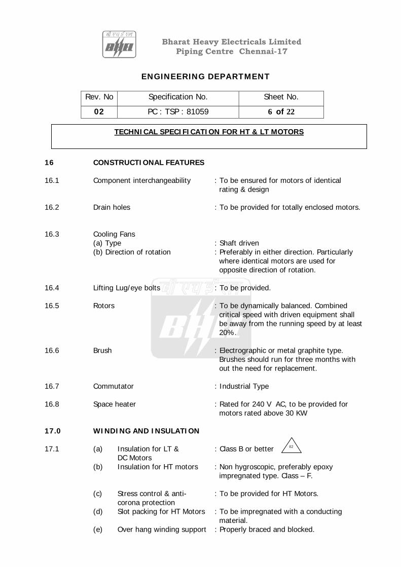
ENGINEERING DEPARTMENT
Rev. No Specification No. Sheet No.
02 PC : TSP : 81059 6 of 22
TECHNICAL SPECIFICATION FOR HT & LT MOTORS
Bharat Heavy Electricals LimitedPiping Centre Chennai-17
16 CONSTRUCTIONAL FEATURES 16.1 Component interchangeability : To be ensured for motors of identical rating & design 16.2 Drain holes : To be provided for totally enclosed motors. 16.3 Cooling Fans
(a) Type : Shaft driven (b) Direction of rotation : Preferably in either direction. Particularly
where identical motors are used for opposite direction of rotation.
16.4 Lifting Lug/eye bolts : To be provided. 16.5 Rotors : To be dynamically balanced. Combined critical speed with driven equipment shall be away from the running speed by at least 20%. 16.6 Brush : Electrographic or metal graphite type. Brushes should run for three months with out the need for replacement. 16.7 Commutator : Industrial Type 16.8 Space heater : Rated for 240 V AC, to be provided for motors rated above 30 KW 17.0 WINDING AND INSULATION 17.1 (a) Insulation for LT & : Class B or better DC Motors (b) Insulation for HT motors : Non hygroscopic, preferably epoxy impregnated type. Class – F.
(c) Stress control & anti- : To be provided for HT Motors. corona protection
(d) Slot packing for HT Motors : To be impregnated with a conducting material.
(e) Over hang winding support : Properly braced and blocked.
02
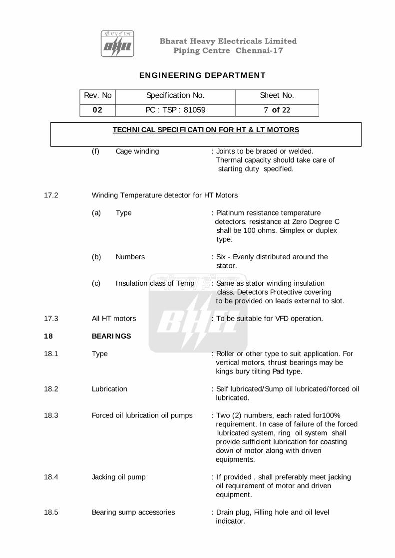
ENGINEERING DEPARTMENT
Rev. No Specification No. Sheet No.
02 PC : TSP : 81059 7 of 22
TECHNICAL SPECIFICATION FOR HT & LT MOTORS
Bharat Heavy Electricals LimitedPiping Centre Chennai-17
(f) Cage winding : Joints to be braced or welded. Thermal capacity should take care of starting duty specified.
17.2 Winding Temperature detector for HT Motors
(a) Type : Platinum resistance temperature detectors. resistance at Zero Degree C shall be 100 ohms. Simplex or duplex type.
(b) Numbers : Six - Evenly distributed around the
stator. (c) Insulation class of Temp : Same as stator winding insulation
class. Detectors Protective covering to be provided on leads external to slot.
17.3 All HT motors : To be suitable for VFD operation. 18 BEARINGS 18.1 Type : Roller or other type to suit application. For vertical motors, thrust bearings may be kings bury tilting Pad type. 18.2 Lubrication : Self lubricated/Sump oil lubricated/forced oil lubricated. 18.3 Forced oil lubrication oil pumps : Two (2) numbers, each rated for100% requirement. In case of failure of the forced lubricated system, ring oil system shall provide sufficient lubrication for coasting down of motor along with driven equipments. 18.4 Jacking oil pump : If provided , shall preferably meet jacking oil requirement of motor and driven equipment. 18.5 Bearing sump accessories : Drain plug, Filling hole and oil level indicator.
ENGINEERING DEPARTMENT
Rev. No Specification No. Sheet No.
02 PC : TSP : 81059 8 of 22
TECHNICAL SPECIFICATION FOR HT & LT MOTORS
Bharat Heavy Electricals LimitedPiping Centre Chennai-17
18.6 Lubricating oil temperature : 71 Degree C at bearing outlet. 18.7 Instrumentation (for HT motors) : Dial type thermometer with adjustable alarm Contact & Resistance Temperature Detectors. (RTD) for each bearing.
RTD type : Duplex, Three wire. Hundred ohms at zero deg.C.
18.8 Prevention of Shaft Current : For motors above 1000 KW (a) Bearing insulation : For pedestal mounted bearing, both bearings to be insulated. Earth bonding link at drive end bearing.
(b) other measures : Water /oil pipe connections etc. to be
insulated as necessary. : Insulation to be meggered at 500 volts. 19.0 HEAT EXCHANGERS : To be provided with 15% excess tubes. 19.1 Air to air heat exchangers : For motors rated above 1000 KW, dial type
thermo meter with adjustable alarm contacts shall be provided to measure primary air inlet and outlet temperature.
19.2 Air to water heat exchanger : Cooler tubes of stainless steel 304 or 70/30 brass. : Flow switch to be provided. : Water leakage detector to be provided. : Pipe flange connections, drain cock, air release plug etc. shall be external to motor. 19.3 Hydraulic Pressure withstand : 1.5 times the maximum working pressure or 3.5 bar (g) whichever is higher. 20.0 TERMINAL BOX 20.1 General : Separate terminal box for power and instrumentation.
02

ENGINEERING DEPARTMENT
Rev. No Specification No. Sheet No.
02 PC : TSP : 81059 9 of 22
TECHNICAL SPECIFICATION FOR HT & LT MOTORS
Bharat Heavy Electricals LimitedPiping Centre Chennai-17
(a) Details of owner’s Cables : Copper/Aluminium conductors. Exact details
to be intimated to successful Bidder. (b) Glands : Single compression nickeled chrome finish brass. (c) Lugs : Tinned copper lugs. For motors rated higher than 160 KW lugs shall conform to DIN 46329 20.2 For HT motors : Phase separated type, capable of being turned through 180 degree. OR provided with Elastimold-type termination kits.
(a) Distance between gland : Not less than 500 mm Plate and terminal
(b) Accessories if Elastimold : Complete accessories along with heat
Offered shrinkable trifurcating sleeves for 3 core cable. Where two cables per phase is envisaged, six sets of apparatus bushing
and elbow connectors are to be provided.
: Metal enclosure with open bottom. 20.3 (A) For LT motors : Terminal box capable of being turned through 180 degree.
Distance between gland plate & : As follows Terminals
Minimum distance between Motor MCR in KW Cable Size center of stud and gland plate in MM 1 2 3 Up to 3 KW 3Cx2.5 Sq.mm (Cu) As per manufacture’s practice. PVC insulated
ENGINEERING DEPARTMENT
Rev. No Specification No. Sheet No.
02 PC : TSP : 81059 10 of 22
TECHNICAL SPECIFICATION FOR HT & LT MOTORS
Bharat Heavy Electricals LimitedPiping Centre Chennai-17
Above 3 KW – up to 7 KW 3Cx6 Sq.mm (Al) 85 PVC insulated Above 7 KW – up to 13 KW 3Cx16 Sq.mm (Al) 115 PVC insulated Above 24 KW – up to 37 KW 3Cx70 Sq.mm (Al) 196 PVC insulated Above 37 KW – up to 55 KW 3Cx120 Sq.mm (Al) 249 PVC insulated Above 55 KW – up to 90 KW 3Cx150 Sq.mm (Al) 277 XLPE insulated Above 90 KW – up to 110 KW 3Cx240 Sq.mm (Al) 331 XLPE insulated Above 110 KW – up to 200 KW 3-1/2Cx300 Sq.mm (Al) 203 XLPE insulated
(B) For HT Motors : At the time of PO
21.0 NEUTRAL CURRENT
TRANSFORMERS (CTs) : Neutral CTs of PS class shall be provided on each phase, for motors rated 2000 kW and above. These shall be star connected.
21.1 Star formation : In separate terminal box. Terminals to be brought out through bushings. 21.2 Location of CTs : In above terminal box. 21.3 CT type : Epoxy cast resin class PS. Parameters to be given to successful Bidder. 22.0 EARTHING TERMINALS : Two numbers, on opposite side suitable for bolted connection. 23.0 RATING PLATE : To be provided indicating KW rating at specified cooling medium with corresponding temperature rise.
: Bearing identification number.
02
02
02

ENGINEERING DEPARTMENT
Rev. No Specification No. Sheet No.
02 PC : TSP : 81059 11 of 22
TECHNICAL SPECIFICATION FOR HT & LT MOTORS
Bharat Heavy Electricals LimitedPiping Centre Chennai-17
: For ball/roller bearing, recommended lubricant. 24.0 PAINT & FINISH : Minimum one coat of primer and two coats of finished enamel paint. Paint shade – 692 for indoors. 631 for outdoors.
* Details will be confirmed to successful bidder
25.0 FASTENERS : Corrosion resistant material or cadmium plated. : Current carrying fasteners shall be of stainless steel/high tensile brass/copper. 26.0 QUALITY ASSURANCE 26.1 All materials, components and equipments covered under this specification shall
be procured. manufactured, erected, commissioned and tested as per a comprehensive quality assurance program to be approved by the owner. A complete quality plan shall be furnished for the motor rated above 50 KW. All welding and brazing operation shall be carried out as per approved welding and brazing procedure and by qualified welder/brazers.
26.2 The bidder shall also furnish copies of the reference documents/plant
standards/acceptance norms/ test and inspection procedure etc. for Owner’s review/approval. In these approved quality plans, Owner shall identify customer hold points(CHP), which shall be carried out in the presence of the Owner’s representative and beyond which work shall not proceed with out the consent of Owner’s representative in writing.
26.3 Owner reserves the right to witness any of the tests and verify the documents of
the contractor and his sub contractor. No materials/equipments shall be dispatched from the manufacturer’s works before the same is duly cleared for dispatch by the Owner.
26.4 All the sub vendors proposed by the Contractor for procurement of major bought
out items including raw materials, semi- finished components shall be subject to Owner’s approval.
26.5 The Contractor shall carry out an inspection and testing program during
manufacture in his works, and that of his sub- contractor’s to ensure the mechanical accuracy of components, compliance with drawings, conformance to functional and performance requirements, identity and acceptability of all materials,parts and equipments. He shall carry out all tests/ inspection required to
02

ENGINEERING DEPARTMENT
Rev. No Specification No. Sheet No.
02 PC : TSP : 81059 12 of 22
TECHNICAL SPECIFICATION FOR HT & LT MOTORS
Bharat Heavy Electricals LimitedPiping Centre Chennai-17
establish that the items/equipments conform to requirements of the specification and the relevant codes/standards specified in the specification , in addition to carry out tests as per the approved Quality plan.
26.6 Quality audit/ surveillance/ approval of the results of the test and inspection will
not, however, exclude the right of the Owner to reject the equipment if it does not comply with the specification when erected or does not give complete satisfaction in service and the above shall in no way limit the liabilities, and responsibilities of the contractor in ensuring complete conformance of the materials / equipments supplied to relevant specification, standard, data sheets, drawing etc.
26.7 Indicating tests/checks to be carried out for the motors rated above 50 KW during
manufacturing are to be listed by manufacturer. 27.0 TESTS
(a) All motors shall be subjected to routine tests. All LT motors shall be of type tested quality. For each type and rating of HT motor, type tests, shall be carried out.
(b) The tests shall be carried out as per applicable standards including all
special tests. The list of routine tests and type tests are given below: 27.1 Induction motors 27.2 Routine Test
For all the motors:
(a) Visual check (i) Marking on rating plates. (ii) Appearance and painting (iii) Location and details of terminal boxes and accessories (iv) Check for phase sequence and terminal markings.
(b) Dimensional check
(c) Insulation resistance test for winding, space heater and RTD
(d) Measurement of resistance of windings, space heater and RTD
ENGINEERING DEPARTMENT
Rev. No Specification No. Sheet No.
02 PC : TSP : 81059 13 of 22
TECHNICAL SPECIFICATION FOR HT & LT MOTORS
Bharat Heavy Electricals LimitedPiping Centre Chennai-17
(e) High voltage test on windings, space heater and RTD followed by insulation resistance test.
(f) No load test.
(g) Locked rotor test (For all the ratings of motors as per IS 4029)
(h) Reduced voltage running test at no load.
(i) Over speed test.
(j) Vibration measurement at rated speed and rated voltage.
(k) Degree of protection test for IP 54 & IP 55 enclosure (It shall not be
possible to insert a feeler gauge of 0.1 mm thick in the enclosure or flange faces)
Additional routine tests for HT motors only
(l) Shaft voltage measurement.
(m) Tan delta tests on windings and also on individual phases.
(n) Polarization index measurement (The PI value with 2.5 KV shall be not less than 2.0)
(o) Measurement of bearing temperature during steady state conditions.
(p) Functional check on auxiliaries.
27.3 Type Tests For all the motors.
(a) All the tests as listed under routine tests.
(b) Measurement of noise at no load.
(c) Momentary overload test.
(d) Full load test to determine efficiency, power factor and slip.
(e) Pull out torque measurement.
02
02
ENGINEERING DEPARTMENT
Rev. No Specification No. Sheet No.
02 PC : TSP : 81059 14 of 22
TECHNICAL SPECIFICATION FOR HT & LT MOTORS
Bharat Heavy Electricals LimitedPiping Centre Chennai-17
(f) Temperature rise test During test winding temperature, bearing
temperature, core temperature, coolant flow and its temperature shall be recorded at various intervals In case the test is carried out at other than rated load specific approval for the test method and procedure shall be obtained. Wherever ETD’s are provided the temperature shall be measured by ETD also.
(g) Degree of protection test for the enclosure followed by IR, HV and no load
run test.
(h) Fault level withstand test for terminal box. (For breaker controlled motors only).
(i) Measurement of no load starting time & starting current.
Additional type tests for HT motors only.
(j) No load saturation and loss curves (up to approximately 115% of rated voltage)
(k) Surge withstand test for main insulation on a sample coil after placing it in
stator Core with at least five impulses on 1.2/50 micro sec. Wave at test voltages indicated in Annexure – A
(l) Surge withstand test for inter turn insulation on each type of motor coil
with at least five impulses of 0.3/3 micro sec. At test voltages indicated in Annexure–A This test shall be followed by one minute power frequency high voltage test on turn to turn insulation after cutting the coil and bringing out turns suitably. The test voltage shall be mutually agreed upon.
(m) Determination of magnetic center (for pedestal mounted bearing motors
only.) 27.4 When tests to determine the break away starting current of cage induction motors
are taken at reduced voltage, due allowance shall be made for the effect of saturation and the estimated value of break away starting current at rated voltage shall be given on all test certificates.
ENGINEERING DEPARTMENT
Rev. No Specification No. Sheet No.
02 PC : TSP : 81059 15 of 22
TECHNICAL SPECIFICATION FOR HT & LT MOTORS
Bharat Heavy Electricals LimitedPiping Centre Chennai-17
27.5 DC motors shall be subjected to all routine and type tests as per IS :4722. In addition following tests shall be carried out. (a) Noise level measurement as type test.
(b) Vibration measurement as routine test.
(c) Degree of protection test as per IS:4691 as type test.
28.0 COMMISSIONING CHECKS (If called for)
Commissioning checks should be carried out as per IS: 900 and other relevant standards.
29.0 DOCUMENTS REQUIRED 29.1 With bid (3 sets)
(a) Filled in motor data sheet (b) Catalogue (c) Q.P (d) Compliance / Deviation list
29.2 With supplies (15 Sets)
(a) Filled in motor data sheet (b) Catalogue (c) Q.P (d) Test report.

ENGINEERING DEPARTMENT
Rev. No Specification No. Sheet No.
02 PC : TSP : 81059 16 of 22
TECHNICAL SPECIFICATION FOR HT & LT MOTORS
Bharat Heavy Electricals LimitedPiping Centre Chennai-17
ANNEXURE - A
TECHNICAL PARAMETERS FOR MOTORS
11KV SYSTEM
3.3/6.6 KV SYSTEM
415/380 V SYSTEM
220 V DC
1.0 Supply system a) Nominal system volt b) Voltage variation c) Frequency d) Frequency variation e) Combined voltage and frequency variation
11KV +/- 6% 50 Hz + 5 to –5% 10%
3.3/6.6 KV +/-10% 50 Hz + 5 to –5% 10%
415/380/240 V +/-10% 50 Hz +5 to –5% 10%
220 V 190 to 240V
2.0 Permissible rating in each voltage level.
> 1500 KW
> 160 KW (for coal handling & ash conveyor > 200 KW and up to 1500 KW (for other motors.)
< 0.2 KW (for 240 V) > 0.2 & up to 200 KW (for 415/380 V)
3.0 Fault Level
40 kA rms for 1 sec
40 kA rms for 1 sec
45 kA rms for 1 sec
-
4.0 Minimum starting voltage available
75% (for more than 4000 KW) 80% (> 1500 KW & up to 4000 KW)
85% (for up to 1000 KW) 80% (> 1000 KW & up to 1500 KW 90% (for coal mill motor of < 1000 KW)
80% (for more than 110 KW) 85% (for up to 110 KW)
190 V
5.0 Class of insulation
Class F with B limits.
Class F with B limits.
Class B
Class B
6.0 1.2/50 micro sec impulse withstand level for main insulation
49 KV
19/36 KV
-
02

ENGINEERING DEPARTMENT
Rev. No Specification No. Sheet No.
02 PC : TSP : 81059 17 of 22
TECHNICAL SPECIFICATION FOR HT & LT MOTORS
Bharat Heavy Electricals LimitedPiping Centre Chennai-17
7.0 0.3/3 micro sec surge withstand level for interturn insulation
32.0 KV
12.0/24.0 KV
-
8.0 High frequency over voltage test value
27 KV
8/16 KV
9.0 Terminal box a) Fault withstand level for 0.12 sec. b) Clearance between bare live parts. c) Clearance between bare live parts & earth
750 MVA 130 mm 120 mm
150/250 MVA 70/110 mm* 60/100 mm*
31 MVA (for > 125 KW) 12.5 mm 12.5 mm
10mm 10 mm
02
02
ENGINEERING DEPARTMENT
Rev. No Specification No. Sheet No.
02 PC : TSP : 81059 18 of 22
TECHNICAL SPECIFICATION FOR HT & LT MOTORS
Bharat Heavy Electricals LimitedPiping Centre Chennai-17
ANNEXURE – B
PROFORMA OF MOTOR INFORMATION Bidder’s name : 1 GENERAL (i) Manufacturer
(ii) Equipment driven by motor
(iii) Motor type 2 DESIGN AND PERFORMANCE DATA (i) Frame size (ii) Type of duty (iii)Type of enclosure and method of cooling (iv) Applicable standard to which motor generally conforms (v) Type of mounting (vi) Direction of rotation as viewed from non-driving end (vii) Standard continuous rating at 40deg.C ambient temperature as per Indian standard (KW) (viii) Derated rating for specified normal condition ie. 50deg.C ambient temperature (KW) (ix) Rated voltage (Volts)
(x) Rated speed at rated voltage and frequency (r.p.m)

ENGINEERING DEPARTMENT
Rev. No Specification No. Sheet No.
02 PC : TSP : 81059 19 of 22
TECHNICAL SPECIFICATION FOR HT & LT MOTORS
Bharat Heavy Electricals LimitedPiping Centre Chennai-17
(xi) Full load current at rated voltage
and frequency (Amp) (xii) Power factor at rated load (xiii) Efficiency of motor at rated voltage and frequency (without any tolerance) at a) Design duty point (%) b) 100% of full load (%) (xiv) Starting current (amps) at a) 100% voltage b) 85% voltage c) 80% voltage (for boiler feed- pump only) (xv) Torques at a) Starting (Kg-metre)
b) Pull up (Kg-metre)
c) Pull out (Kg-metre) (xvi) Stator winding insulation a) Class & type
b) Tropicalised (Yes / No)
c) Temperature rise over specified ambient of 50deg.C (deg) (xvii) Stator winding connection (xviii) Number of stator terminals brought out
ENGINEERING DEPARTMENT
Rev. No Specification No. Sheet No.
02 PC : TSP : 81059 20 of 22
TECHNICAL SPECIFICATION FOR HT & LT MOTORS
Bharat Heavy Electricals LimitedPiping Centre Chennai-17
(xix) Type of terminal box for
a) Stator leads
b) Space heater c) Temperature detector
(xx) Space heaters a) Number b) Location c) Power requirement (KW) (xxi) Bearing type a) Driving end b) Non driving end (xxii) Type of construction of rotor (xxiii) Weight of a) Motor stator (Kg) b) Motor rotor (Kg) c) Total weight (Kg) (xxiv) Motor starting time (sec) (xxv) Motor rated torque (Kg-met) (xxvi) Motor accelerating torque (Kg-met)
NOTE: INDICATE TOLERANCE VALUES AGAINST EACH DATA

ENGINEERING DEPARTMENT
Rev. No Specification No. Sheet No.
02 PC : TSP : 81059 21 of 22
TECHNICAL SPECIFICATION FOR HT & LT MOTORS
Bharat Heavy Electricals LimitedPiping Centre Chennai-17
ANNEXURE – C
PROFORMA OF DC MOTOR INFORMATION Bidder’s name : 1 GENERAL (i) Manufacturer
(ii) Equipment driven by motor
(iii) Motor type
(iv) Country of origin 2 DESIGN AND PERFORMANCE DATA
(i) Frame size
(ii) Type of duty
(iii) Type of enclosure and method of cooling
(iv) Applicable standard to which motor generally conforms (v) Type of mounting (vi) Standard continuous rating at 40deg.C ambient temperature as per Indian standard (KW) (vii) Derated rating for specified normal condition ie. 50deg.C ambient temperature (KW) (viii) Rated voltage (Volts) (ix) Range of voltage between which from
Volts to Volts the motor can develop rated torque

ENGINEERING DEPARTMENT
Rev. No Specification No. Sheet No.
02 PC : TSP : 81059 22 of 22
TECHNICAL SPECIFICATION FOR HT & LT MOTORS
Bharat Heavy Electricals LimitedPiping Centre Chennai-17
x) Minimum permissible voltage at which motor can develop the required starting torque
(xi) Current at
a) Starting at minimum permissible voltage
b) Rated load (xii) Armature winding a) Class & type of insulation
b) Tropicalised (Yes / No)
c) Commutator material (xiii) Shunt winding a) Class & type of insulation
b) Tropicalisted (Yes / No)
(xiv) Feature incorporated to ensure satisfactory communication during operation
(xv) Type of terminal box (xvi) Motor starter (for motor 10 KW above) a) Type b) Make
(xvii) Space heater (if provided) a) Number
b) Location
c) Power requirement (KW)
(xviii) Weight of motor (Kg)
NOTE: INDICATE TOLERANCE VALUES AGAINST EACH DATA

Specification Number Rev.no. Sheet Number
PC:TSP:LPSS:CON-PUMP:001 00 1 of 1
Bharat Heavy Electricals Limited Piping Centre Chennai-17
TECHNICAL SPECIFICATION FOR CENTRIFUGAL PUMPS-CONDENSATE PUMP FOR LP STARTUP SYSTEM
ANNEXURE-B MANDATORY SPARES
DESCRIPTION QTY
i. All Gaskets in one pump
ii. All O rings in one pump
iii. Gland packing in one pump
iv. Impeller
v. All Pump Bearings in one pump
vi. Shaft
vii. Impeller Lock nut
viii. Shaft Protection Sleeve
ix. Pump Motor coupling complete
x. All Wearing rings in one pump
xi. All Motor Bearings
xii. Motor
2 set
2 set
2 set
2nos
2 set
2 no.
2 no.
2 no.
2 set
2 set
2 set
2nos