document no: asap 2009
TRANSCRIPT

DOCUMENT NO: ASAP 2009 VERSION: 2007-12-12 Page 1 of 6 TITLE: Standard Application Procedures for Experimental Permits Issued Under
30 CFR Part 18 MSHA Mine Safety and Health Administration, Approval & Certification Center
1.0 PURPOSE
1.1. To inform applicants how to apply for Mine Safety and Health Administration (MSHA) Experimental Permit issued per Part 18 of Title of the Code of Federal Regulations (30 CFR Part 18).
1.2. To specify the documentation, equipment and components necessary to evaluate and test a product for compliance with MSHA requirements.
1.3. To identify the Applicant’s responsibilities during the investigation process.
2.0 SCOPE
This procedure is a guide for Applicants requesting Experimental Permit per Part 18 of Title 30 of the Code of Federal Regulations (30 CFR Part 18). Under an Experimental permit, the user has the opportunity to evaluate innovative equipment designs in underground gassy mines or tunnels.
3.0 REFERENCES
3.1. 30 CFR Part 18.82 “Permit to use experimental electric face equipment in a gassy mine or tunnel”
3.2. APOL1009 “Application Cancellation Policy”
These documents are available on www.msha.gov or by contacting the Approval and Certification Center at 304-547-0400.
4.0 DEFINITIONS
4.1. An application for a permit to use experimental electric face equipment in a gassy mine or tunnel will be considered only when submitted by the “user” who operates and monitors the equipment and is responsible for ensuring
ASAP2009 2007-12-12.doc Print Date: 1/31/2008 PRINTED AND ELECTRONIC COPIES OF THIS DOCUMENT ARE UNCONTROLLED. VERIFY CORRECT VERSION PRIOR TO USE. TSAP0001, Rev 01

DOCUMENT NO: ASAP 2009 VERSION: 2007-12-12 Page 2 of 6 TITLE: Standard Application Procedures for Experimental Permits Issued Under
30 CFR Part 18 MSHA Mine Safety and Health Administration, Approval & Certification Center
that any conditions of use associated with the permit are met. When Experimental Permits are issued for equipment developed under a government research contract, the said agency, not the contractor, must submit the application letter. The Experimental Permit will be issued to that agency.
4.2. Should the contractor decide, after completing the research contract, to market the equipment, they must submit an application for approval in their name.
4.3. Even though an Experimental Permit has been issued, additional technical, administrative, and testing criteria may be required before a final approval is granted. Fees covering the approval evaluation will be charged accordingly.
4.4. Experimental Permits can also be issued directly to private parties when no government contract is involved. Should the private party decide to market the experimental equipment, they must submit an application for approval and pay the requisite fee.
4.5. MSHA at its discretion may waive the requirements for detailed drawings of component parts, inspections, and tests provided satisfactory evidence is submitted that an enclosure has been certified, or otherwise accepted by a reputable testing agency whose standards are substantially equivalent to those set forth in subpart B of 30 CFR Part 18.82 (ref: Paragraph 18.82(b)(iii)).
4.6. A permit will be effective for a period of six (6) months. For a valid reason, to be stated in a written application, MSHA may grant an extension of time for an additional period, not exceeding six (6) months. Further extensions of time will be granted only where, after investigation, MSHA finds that for reasons beyond the control of the user, it has been impossible to complete the experiment within the period covered by the extended permit.
4.7. Once a permit is issued, modifications (for design changes) to the permit may be granted; however, the expiration date of the permit will not change. A separate request must be submitted to extend the time limit. Major changes will require a new permit application.
ASAP2009 2007-12-12.doc Print Date: 1/31/2008 PRINTED AND ELECTRONIC COPIES OF THIS DOCUMENT ARE UNCONTROLLED. VERIFY CORRECT VERSION PRIOR TO USE. TSAP0001, Rev 01

DOCUMENT NO: ASAP 2009 VERSION: 2007-12-12 Page 3 of 6 TITLE: Standard Application Procedures for Experimental Permits Issued Under
30 CFR Part 18 MSHA Mine Safety and Health Administration, Approval & Certification Center
4.8. If an applicant requires a permit on an intrinsically safe circuit or explosion-proof enclosure, which is part of a complete machine, the applicant must submit the permit application for the complete machine. Permits are not issued for separate intrinsically safe circuits or explosion-proof enclosures. They will be evaluated as part of the machine permit on which these intrinsically safe circuits or explosion-proof enclosures are installed.
4.9. A permit does not give the authorization to advertise or market the equipment as permissible for use in gassy mines or tunnels.
4.10.MSHA may rescind, for cause, any experimental permits granted.
5.0 APPLICATION PROCEDURE
5.1. Considerable time and money can be saved if the application includes the required information necessary to ascertain compliance with Title 30 Code of Federal Regulations (30 CFR) Part 18. These regulations are accessible from the MSHA website at www.msha.gov
5.2. A copy of 30 CFR can be purchased from:
Superintendents of Documents P.O. Box 371954 Pittsburgh, PA 15250-7954 Telephone: 202-512-1800
5.3. All applications for an Experimental Permit must include the following:
5.4. Application letter. This letter (Reference Enclosure) should include the following information:
5.4.1. Applicant’s name and address, and signed by the person responsible for answering questions regarding the subject application (the user of the equipment);
5.4.2. Application date;
ASAP2009 2007-12-12.doc Print Date: 1/31/2008 PRINTED AND ELECTRONIC COPIES OF THIS DOCUMENT ARE UNCONTROLLED. VERIFY CORRECT VERSION PRIOR TO USE. TSAP0001, Rev 01

DOCUMENT NO: ASAP 2009 VERSION: 2007-12-12 Page 4 of 6 TITLE: Standard Application Procedures for Experimental Permits Issued Under
30 CFR Part 18 MSHA Mine Safety and Health Administration, Approval & Certification Center
5.4.3. A six digit Company or Government Agency Application Code Number assigned by the Applicant. This number is used to identify the application and should not have been assigned to an application previously submitted by the Applicant;
5.4.4. The name, address, telephone number, FAX number and e-mail address of the person MSHA is to contact regarding the application and billing;
5.4.5. Type of machine or instrument;
5.4.6. Model/Type number, operating voltage, number of phases, frequency, current (ac or dc);
5.4.7. Serial number of machine or instrument;
5.4.8. A general description of the machine or instrument. For a machine, include details on function/operation and any unusual characteristics of the machine, either electrically or mechanically. For an instrument, include a technical description of the circuit operation with special emphasis on intrinsic safety design features;
5.4.9. For a machine, location and date for MSHA inspection; (if known)
5.4.10. Location where the machine or instrument will be used; (if known)
5.4.11. One copy of each drawing(s), bill of material, specifications, etc., which shows the details of the design and construction of the equipment as related to the applicable requirements of 30 CFR, Part 18;
5.4.12. Additional information to expedite the investigation can include photos, test reports, or literature. For any new equipment or circuits which are similar to previously accepted MSHA designs, the MSHA Acceptance Number (if known) of the previously accepted design should be referenced in the application letter;
5.4.13. Checklists are attached to assist the applicant in providing sufficient information to MSHA. (See Appendix A for machine checklist and Appendix B for an instrument checklist.) It should be noted that additional information may be required due to the great variety of mining machines.
ASAP2009 2007-12-12.doc Print Date: 1/31/2008 PRINTED AND ELECTRONIC COPIES OF THIS DOCUMENT ARE UNCONTROLLED. VERIFY CORRECT VERSION PRIOR TO USE. TSAP0001, Rev 01

DOCUMENT NO: ASAP 2009 VERSION: 2007-12-12 Page 5 of 6 TITLE: Standard Application Procedures for Experimental Permits Issued Under
30 CFR Part 18 MSHA Mine Safety and Health Administration, Approval & Certification Center
5.5. Submit the application to MSHA by one of the following methods:
5.5.1. Mail to: MSHA Approval and Certification Center Attention: IPSO
RR #1, Box 251 Industrial Park Road Triadelphia, WV 26059
5.5.2. FAX to: 304-547-2044
5.5.3. Electronically: For information and instructions on setting up an account with MSHA go to http://www.msha.gov/techsupp/acc/application/online.htm.
5.6. Additional Information. Applicants may contact the Electrical Safety Division at 304-547-0400 for additional information concerning these procedures.
5.7. Upon receipt of the application package by the Approval and Certification Center a letter will be written to the applicant that includes an estimate of the maximum anticipated fee to complete the investigation and a tentative starting date. An authorization response form will also be included which indicates agreement to pay expenses up to the maximum estimated fee for the investigation or requests cancellation of the application. This form must be returned by the applicant before any further action is taken on the application. If the form letter is not returned within thirty days from the date of the letter, the application will be canceled. When unforeseen circumstances encountered during the investigation may result in exceeding the estimated fee, the applicant will be contacted and given the option of canceling the action or accepting the new estimated fee. It should be noted that no fees will be charged to agencies of the United States Government.
5.8. During the investigation, applicants will be notified via a telephone or e-mail message of any discrepancies or additional information needed to process the application and a follow-up letter will then be sent. After all the technical documents are evaluated, an inspection will be required on the equipment. Once this is completed and any changes required as a result of
ASAP2009 2007-12-12.doc Print Date: 1/31/2008 PRINTED AND ELECTRONIC COPIES OF THIS DOCUMENT ARE UNCONTROLLED. VERIFY CORRECT VERSION PRIOR TO USE. TSAP0001, Rev 01

DOCUMENT NO: ASAP 2009 VERSION: 2007-12-12 Page 6 of 6 TITLE: Standard Application Procedures for Experimental Permits Issued Under
30 CFR Part 18 MSHA Mine Safety and Health Administration, Approval & Certification Center
the inspection are finalized, the official experimental permit number will be issued. An invoice for the total cost of the investigation will then follow.
ASAP2009 2007-12-12.doc Print Date: 1/31/2008 PRINTED AND ELECTRONIC COPIES OF THIS DOCUMENT ARE UNCONTROLLED. VERIFY CORRECT VERSION PRIOR TO USE. TSAP0001, Rev 01

SAMPLE LETTER
ABC Company, 950 Mining Road, Pittsburgh, PA 15293
December 12, 2007
Chief, Approval and Certification Center RR #1, Box 251, Industrial Park Road Triadelphia, West Virginia 26059
Gentlemen:
This is a request for an experimental permit for a new continuous miner, Model 100, 4160 volt, 3 phase, 60 hertz, alternating current, Company Code No. 010100.
We are requesting approval of the subject continuous miner assembled according to Layout Drawing 100.
The subject shearer consists of two (2) 300 hp cutter motors, one (1) 20 hp hydraulic motor, one (1) starter, and two (2) pushbutton stations. This machine is fully autonomous, and is monitored from an outby area of the mine.
Since this is a prototype continuous miner, it will be completely assembled and available for inspection on July 1, 2004, at the ABC Company, Do Little Mine, 950 Mining Road, Pittsburgh, Pennsylvania 15293.
Enclosed are all the drawings and specifications pertinent to this application. If there are any questions, please contact Mr. John Smith at (555) 555-0001.
Sincerely,
John Doe Design Engineer Enclosure
Enclosure

MACHINE CHECKLIST
Complete all of the following by adding a check mark or N/A on the lines provided. The check mark signifies the item has been positively addressed. N/A signifies the item is not applicable to the design of the machine/system.
Administrative
______ 1. An application letter is enclosed.
______ 2. All correspondence, specifications and lettering on documents are in English or translated into English and legible.
______ 3. All documents are titled, numbered, dated, and show the latest revision or date. If multiple pages are submitted, this information is on each page.
Technical
4. The assembly drawing(s) includes the following:
______ a. The overall length, width and height of the machine.
______ b. Location of all electrical enclosures and intrinsically safe components.
______ c. Location of the permit plate and method of attachment.
______ d. An insulated strain relief device where the trailing cable enters the machine, where cables exit a battery enclosure on battery-powered equipment and at both ends of all cables leading to components not on a common frame.
Note: A drawing of the device must be submitted or referenced if on file with MSHA. Cable grip type strain relief devices are not accepted where the cable is placed alternately in tension.
Appendix A Sheet 1

______ 5. The location of all cables entering/exiting electrical enclosures is shown.
6. All inter component cables are identified by:
______ a. Conductor size, (e.g., 1/0 A.W.G.).
______ b. Type of cable, (e.g., G-GC).
______ c. Number of conductors, (e.g., 3).
______ d. Electrical rating, (e.g., 2KV).
______ e. Outer diameter, (e.g., 1.65", +.04").
______ f. Conductor temperature rating in degrees centigrade (e.g., 90ºC) or the ampacity.
7. The trailing cable is identified by:
______ a. Conductor size, (e.g., 4/0 A.W.G.)
______ b. Type of cable, (e.g., SHD-GC).
______ c. Number of conductors, (e.g., 3).
______ d. Electrical rating, (e.g., 2KV).
______ e. Outer diameter, (e.g., 2.31", +5%).
______ f. Conductor temperature rating in degrees centigrade, (e.g., 90ºC).
______ g. Type of insulation, (e.g., EPR).
______ h. Maximum length, (e.g., 500´).
Note: The trailing cable nominal outer diameter and ampacity must be consistent with Insulated Cable Engineers Association (ICEA) Standards.
Appendix A Sheet 2

8. All explosion-proof electrical enclosures are identified by:
______ a. Manufacturer.
______ b. Model/Type Number (for motors, specify frame number).
______ c. Electrical Rating (if applicable). For motors, specify voltage, phase, hertz, ac or dc, horsepower and full load amperes; and for headlights, specify voltage and wattage.
______ d. Function, (e.g., pump motor, controller).
______ e. Certification number, including extension number. If the original issuance is used, indicate (-0).
Note: If no certification number was issued, indicate the approval number and model number under which it was accepted.
______ f. Quantity.
9. All intrinsically safe circuits/components are identified by:
______ a. Manufacturer.
______ b. Model/Type Number.
______ c. Quantity.
______ d. MSHA Evaluation Number, including extension number. If the original issuance is used, indicate (-0).
10. If maximum tramming speed of the machine is greater than 2.5 mph;
______ a. An audible warning device is specified and shown on the assembly drawing.
______ b. At least one headlight is installed and red light-reflecting material (minimum 10 square inches each) is specified for both the front and rear of the machine.
Appendix A Sheet 3

______
______
______
______
______
______
Note: Reflective paint is not acceptable to meet this requirement. Also, it is recommended that all mobile equipment have red-reflective material.
c. A cable reel is provided for line powered equipment.
11. If the maximum length of the trailing cable exceeds 500 feet, the maximum starting inrush current is specified and the outby circuit breaker or protective device is specified and set as close as practicable to this value. The trip setting and cable length does not exceed the values in Tables 8 and 9 of 30 CFR, Part 18.
12. If the machine is a boring-type continuous miner, a view is shown depicting at least 200 square inch cross-sectional area for auxiliary face ventilation.
Note: Two or more spaces are acceptable as long as their total cross-sectional area is a minimum 200 square inches.
13. If the machine is equipped with a powered dust collector, the MSHA 25B Approval Number (for the dust collector) is specified on the application letter or the drawings.
Note: If a "Wet Dust Collecting System" or other system is used, this should be indicated.
14. If the machine is equipped with a belt conveyor, the design includes control switches to automatically stop the driving motor in the event the belt is stopped or abnormally slowed down. The drawing(s) indicate whether a belt or chain conveyor is used.
Note: Short transfer-type conveyors will be exempted from this requirement.
15. If the machine is equipped with a cable reel, at least one slip-ring is used for the ground circuit. The cable reel spooling devices*, such as the hub, flange, cable guide, sheave, etc. that the trailing cable normally contacts are all insulated with flame-resistant material. The cable guide and sheave material is specified on the documents
Appendix A Sheet 4
______
______
______
______
______
as MSHA flame-resistant and the manufacturer, material and MSHA number (if issued) are identified.
*Note: Isolated components, insulated from the machine frame, are acceptable if they are inaccessible to personnel during normal operation of the machine. These components do not need to be insulated from the cable.
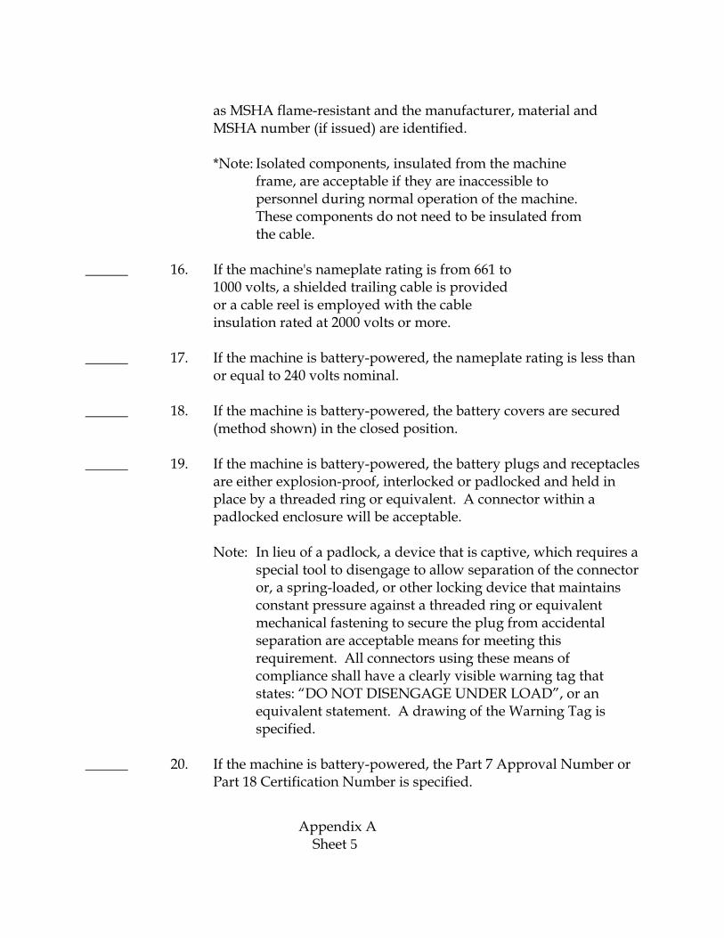
16. If the machine's nameplate rating is from 661 to 1000 volts, a shielded trailing cable is provided or a cable reel is employed with the cable insulation rated at 2000 volts or more.
17. If the machine is battery-powered, the nameplate rating is less than or equal to 240 volts nominal.
18. If the machine is battery-powered, the battery covers are secured (method shown) in the closed position.
19. If the machine is battery-powered, the battery plugs and receptacles are either explosion-proof, interlocked or padlocked and held in place by a threaded ring or equivalent. A connector within a padlocked enclosure will be acceptable.
Note: In lieu of a padlock, a device that is captive, which requires a special tool to disengage to allow separation of the connector or, a spring-loaded, or other locking device that maintains constant pressure against a threaded ring or equivalent mechanical fastening to secure the plug from accidental separation are acceptable means for meeting this requirement. All connectors using these means of compliance shall have a clearly visible warning tag that states: “DO NOT DISENGAGE UNDER LOAD”, or an equivalent statement. A drawing of the Warning Tag is specified.
20. If the machine is battery-powered, the Part 7 Approval Number or Part 18 Certification Number is specified.
Appendix A Sheet 5

______ 21. If the machine is battery-powered, short-circuit protection is provided for each wire or cable leaving the battery box and the protective device is in an explosion-proof enclosure as close as practical to the battery terminals.
Note: Protective devices installed within a nearby explosion-proof enclosure will be acceptable provided the exposed portion of the cable does not exceed 36 inches.
______ 22. All plugs and receptacles are explosion-proof or mechanically or electrically interlocked unless used in an intrinsically safe circuit.
Note: Complete Item 20 for battery plugs and receptacles.
______ 23. If the machine is line powered by direct current, the nameplate rating is less than or equal to 550 volts.
______ 24. All remote control cables are intrinsically safe or constructed of a heavy jacket with conductors no smaller than No. 14 (AWG), if not enclosed in hose conduit. If enclosed in hose conduit, the cable tensile strength is not less than No. 16 (AWG) 3 conductor.
______ 25. The trailing cable is minimum No. 4 (AWG) for direct current mobile haulage units, minimum No. 6 (AWG) for alternating current haulage units, and minimum No. 14 (AWG) with sizes 14 to 10 constructed of heavy jackets for face equipment.
______ 26. The trailing cable ampacity rating is adequate for the total full load current of the machine or a justification for a lesser rating based on the machine's duty cycle is enclosed with the application.
______ 27. The ampacity rating for each inter-component cable is adequate for the full load current of its load or a justification for the use of the cable is enclosed with the application.
______ 28. If the machine is equipped with a methane monitor, the methane monitor power shut-off relay de-energizes all motors, lighting circuits and power take-off receptacles.
Appendix A Sheet 6

______ a. The shut-off relay is connected into the control circuitry so that it is not possible to defeat the methane monitor by holding down or blocking any reset (start) switch in the start position.
______ b. The control circuitry is connected so that none of the electrical motors will restart automatically when the methane monitor shut-off relay is deactivated.
Note: Intrinsically safe circuits and the methane monitor may remain energized.
______ 29. All energy storage devices (not including batteries) housed in explosion-proof enclosures have a means of being discharged before they are accessible to personnel. The maximum discharge time of the device is specified on the drawing.
______ 30. The cross-sectional area(s) of the grounding conductor(s) is at least 50 percent of one of the power conductors on No. 6 (AWG) or larger cables, and at least the same size on cables smaller than No. 6 (AWG).
______ 31. There are no insulating materials in the enclosures that give off flammable or explosive gases when decomposed electrically. Additionally, all parts coated or impregnated with insulating materials were heat treated to remove any combustible solvents before assembly.
Note: Air drying insulating materials is accepted.
______ 32. The temperature of the external surfaces of the mechanical or electrical components does not exceed 150ºC (302ºF) under normal operating conditions.
______ 33. If the machine is equipped with fiber optic cable(s), they do not contain current-carrying electrical conductors and also meets the following criteria.
______ i. The cable is MSHA accepted flame-resistant unless totally enclosed within an MSHA flame-resistant hose conduit or
Appendix A Sheet 7

other MSHA flame-resistant material, or totally contained within an explosion-proof enclosure.
______ ii. A strain relief device is provided at both ends of the cable where it enters an explosion-proof enclosure not on a common frame.
______ iii. All the conductive members are grounded on cables which contain non-current carrying conductive members, such as metallic strength members and metallic vapor barriers.
______ iv. Any cable exiting an explosion-proof enclosure was explosion tested in a gland arrangement similar to that being used and in an MSHA tested enclosure at a pressure of approximately 150 psi or the tests were waived based on a previously accepted similar design.
______ v. The cable manufacturer, type and outside diameter (including tolerance) is specified.
Note: Cables which contain both optical fibers and current-carrying electrical conductors will be classified as electrical cables and must meet the requirements of 30 CFR Part 18.
______ 34. All circuit-interrupting devices can be reset without opening the compartment in which they are enclosed and no explosion-proof enclosure is required to be opened to operate a switch, rheostat or other device.
______ 35. All components and quantities (motors, solenoids, lights, ISC components, etc.) listed on the bill of materials, etc., are also shown on the layout and schematic/wiring diagram(s).
36. The schematic/wiring diagram(s) includes/specifies the following (where applicable).
______ a. Short-circuit protective devices for all cables exiting explosion-proof enclosures, including their electrical ratings and trip settings, in amperes.
Appendix A Sheet 8

Note: If one protective device is used to protect several cables, the protective device must protect the smallest cable.
______ b. Primary and secondary transformer voltages and any voltage change from ac to dc.
______ c. Labels for all major switches (as to functions), example, emergency stop switch, pump start, light switch, etc.
______ d. Separate ground connections for trailing cables with ground and ground check conductors, indicating separate termination of these conductors.
______ e. Separate grounding conductors to indicate all headlight and luminaire assemblies are grounded by a separate conductor.
______ f. The machine input voltage(s).
______ g. The voltage of the control circuit.
Note I: The voltage cannot exceed nominal 120 volts line-to-line alternating current.
Note II. Not applicable for direct current.
______ h. A single circuit-interrupting device by means of which all power conductors, including lighting conductors, can be de-energized at the machine.
Note: The device shall simultaneously open all phase conductors on an alternating current machine, and both line conductors on a single phase, alternating current or direct current machine. The interrupting of all conductors shall occur in a single enclosure.
______ i. Overload protection for all motors, including the trip settings in amperes.
Appendix A Sheet 9

Note I: The overload devices must be in at least two phases of an AC motor circuit, the activation of one device must open all three phases.
Note II: If current transformers are used in conjunction with overload devices, the turns ratio must be specified.
______ j. A separate two-pole switch to de-energize all power conductors to headlights and luminaire.
Note I. Relay actuated contactors are not acceptable as the sole means of providing this function.
Note II: More than one separate two-pole switch may be used; however, each switch must only control a lighting circuit.
Note III: On three phase lighting circuits, a three-pole switch must be used.
______ k. Identification of all intrinsically safe circuits by the MSHA evaluation number, including extension number. If the original issuance is used, indicate (-0).
______ l. The note "Any change(s) in the intrinsically safe circuitry or components may result in an unsafe condition."
Note: For each schematic/wiring diagram(s) that contains intrinsically safe circuits.
______ m. Cover interlocks on covers providing access to power fuses (other than headlight and control circuit fuses). The interlock interrupts the electrical circuit in the explosion-proof enclosure and prevents automatic re-energization of the circuit when the explosion-proof integrity of the enclosure is reestablished. The power fuses are located on the load side of the circuit interrupting device.
Appendix A Sheet 10
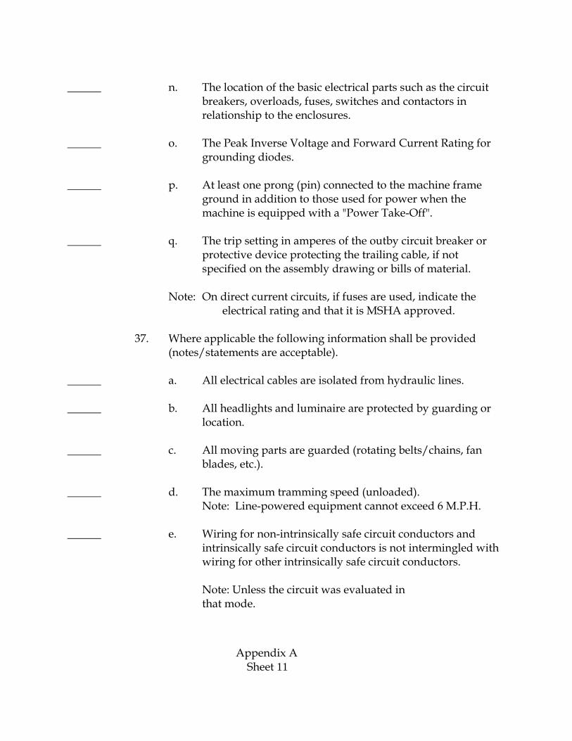
______ n. The location of the basic electrical parts such as the circuit breakers, overloads, fuses, switches and contactors in relationship to the enclosures.
______ o. The Peak Inverse Voltage and Forward Current Rating for grounding diodes.
______ p. At least one prong (pin) connected to the machine frame ground in addition to those used for power when the machine is equipped with a "Power Take-Off".
______ q. The trip setting in amperes of the outby circuit breaker or protective device protecting the trailing cable, if not specified on the assembly drawing or bills of material.
Note: On direct current circuits, if fuses are used, indicate the electrical rating and that it is MSHA approved.
37. Where applicable the following information shall be provided (notes/statements are acceptable).
______ a. All electrical cables are isolated from hydraulic lines.
______ b. All headlights and luminaire are protected by guarding or location.
______ c. All moving parts are guarded (rotating belts/chains, fan blades, etc.).
______ d. The maximum tramming speed (unloaded). Note: Line-powered equipment cannot exceed 6 M.P.H.
______ e. Wiring for non-intrinsically safe circuit conductors and intrinsically safe circuit conductors is not intermingled with wiring for other intrinsically safe circuit conductors.
Note: Unless the circuit was evaluated in that mode.
Appendix A Sheet 11

______
______
______
f. All V-belts are static conducting per Rubber Manufacturer's Association Technical Standards.
g. The magnesium content of any external aluminum alloy fans, pulleys, or other rotating devices does not exceed 0.6%.
h. The machine has a load-locking valve system that meets the Load-Locking Valve that meets the following criteria:
i. The load locking valve must be attached directly to the cylinder port that is subject to the hydraulic pressure induced by the weight of the boom or cutting head, or directly to a section of steel tubing welded to the cylinder port and attached to the cylinder. In either case the load locking valve shall be attached directly to the cylinder in a manner that precludes disconnecting the line between the load locking valve and the cylinder without first detaching the load locking valve from the cylinder.
ii. The rated working pressure of the load locking valve must be greater than the maximum system operating pressure.
iii. If the load locking valve has over pressure relief capability, the over pressure relief setting shall be sufficient to allow proper operation of the load locking valve.
iv. If the load locking valve is pilot operated, the hydraulic system shall be designed to ensure that the residual pilot pressure or line back pressure will not hold the load locking valve open when the control valve is in the neutral position.
v. Adequate hydraulic filtration shall be provided to ensure that the load locking valve will operate properly throughout its normal service life, when the hydraulic system is subjected to rigorous ever day mining conditions.
Note: This statement must be signed original signature) by a registered, professional engineer and must be submitted when the machine/system uses
Appendix A Sheet 12

hydraulic cylinders to elevate cutting heads and conveyor booms on continuous miners and loading machines.
______ i. The voltage ratings of all conductors and cables within the enclosures is compatible with the impressed voltage.
______ j. All components on a common frame are solidly frame grounded when the inter component cable(s) to those components do not have separate grounding conductors.
______ k. The trailing cable is MSHA accepted flame-resistant and all other electrical cables/cords are MSHA accepted flame-resistant or enclosed in MSHA accepted flame-resistant hose conduit.
Note: This includes intrinsically safe cables.
______ l. An MSHA accepted ground wire monitor will monitor the ground connection to the machine and components not on a common frame.
Note: For machines rated in excess of 660 volts.
______ m. All conveyor belting is fire resistant per 30 CFR, Section 18.65.
______ n. No sintered metallic friction materials are used on the equipment unless used in conformance with the exceptions stated in the Approval and Certification Center's policy letter dated May 22, 1979. A&CC's policy is to restrict the use of sintered metallic friction materials to enclosures considered explosion proof or to enclosures that prohibit the outside atmosphere from entering the enclosure. A totally enclosed clutch type brake system is considered acceptable.
______ o. All cables are protected from mechanical damage and clamped in place to prevent undue movement.
Appendix A Sheet 13

______ p. If the machine is wheel mounted, one of the following statements or equivalent is used to describe the parking brakes.
______ i. The parking brake provided holds the machine stationary up to its maximum grade ability despite any contraction of the brake parts, exhaustion of any non-mechanical source of energy, or leakage of any kind.
______ ii. The design of the driving mechanism will preclude accidental movement of the machine when parked.
Note: Small machines such as fans and rock dusters, which are not self-propelled, may use wheel chocks, lock-down bolts and similar devices provided they are shown on the assembly drawing and permanently affixed to the machine. Each device will be separately evaluated to insure the design is adequate.
______ q. All non-certified, accepted explosion-proof enclosures are identified by a permanent marking that consists of the following capital letters, "US MSHA", "US MESA" or "USBM" (not less than 1/4" in height) and enclosed in a circle not less than 1.00" in diameter.
Note: For enclosures that meet all applicable requirements of Part 18, but have not been issued a separate certification number, that is, they have been evaluated and accepted under the total approval investigation. A drawing of the marking must be submitted.
Appendix A Sheet 14

INTRINSICALLY SAFE INSTRUMENT OR CIRCUIT CHECKLIST
This checklist is available for the applicant to use as a guide to ensure that the application package (drawings and specifications) submitted to MSHA is complete. It should be submitted with the application package. Complete all of the following by adding a check mark or N/A on the lines provided. The check mark signifies the item has been positively addressed. N/A signifies the item is not applicable to the design of the system.
Administrative
_____ 1. Is an application letter enclosed?
_____ 2. Is a drawing list in the proper format included in the application package?
_____ 3. Is a caution statement specified and included in the application package?
_____ 4. Are all correspondence, specifications, and lettering on drawings in English?
_____ 5. Are all drawings and Bills of Material titled, numbered, dated, and legible?
_____ 6. Do all revised drawings and Bills of Material show the latest revision and/or date?
_____ 7. Do all wiring diagrams showing intrinsically safe circuits include a warning statement “Any change(s) in the intrinsically safe circuitry or components may result in an unsafe condition”?
Investigative
_____ 1. Does the overall assembly drawing or photograph show the location of each major component?
_____ 2. Are schematic drawings of each electrical circuit included?
_____ 3. Is each battery identified by: Type, voltage, capacity, and manufacturer's name and part number?
_____ 4. Is each transformer identified by: Manufacturer's name and part number, inductance (nominal and tolerance or maximum value) and dc resistance (nominal and tolerance or minimum value), or; specifications showing the physical construction of the transformer to include: core type, insulation rating, size of wire, number of turns, physical dimensions and spacing (clearances) of terminals and maximum temperature rating of insulation? As an alternative, actual samples may be submitted for measurement if not all manufacturer’s information is available.
Appendix B Sheet 1

Is each protective and power transformer identified by: Manufacturer's name and part number, inductance (nominal and tolerance or maximum value) and dc resistance (nominal and tolerance or minimum value), and specifications showing the physical construction of the transformer to include: core type, insulation rating, size of wire, number of turns, physical dimensions and spacing (clearances) of terminals and maximum temperature rating of insulation, transformer type (see ACRI2001, Section 7.2), voltage and current ratings of each winding, high potential or dielectric strength specifications and spacing between windings? As an alternative, actual samples may be submitted for measurement if not all manufacturer’s information is available.
_____ 5. Is each inductor identified by: Manufacturer's name and part number, inductance (nominal and tolerance, or maximum value) and dc coil resistance (nominal and tolerance, or minimum value) and; specifications of the core type, size of wire, insulation, and number of turns? As an alternative, actual samples may be submitted for measurement if not all manufacturer’s information is available.
_____ 6. Is each solenoid identified by: Manufacturer's name and part number; method of measuring coil inductance (nominal and tolerance, or maximum value) or stored energy (nominal and tolerance, or maximum value) at a specified voltage, dc coil resistance (nominal and tolerance, or minimum value) and; specifications of the core type, size of wire, insulation, and number of turns?
_____ 7. Is each mechanical relay identified by: Manufacturer's name and part number, method of measuring coil inductance (nominal and tolerance or maximum value) or stored energy (nominal and tolerance, or maximum value) at a specified voltage, and coil resistance (nominal and tolerance, or minimum value). If the relays are used as protective components to provide intrinsic safety isolation, the maximum dielectric voltage and physical separation (creepage and clearances) between coil, coil terminals, switching contacts, and contact leads must be specified? As an alternative, actual samples may be submitted for measurement if not all manufacturer’s information is available.
_____ 8. Is each capacitor identified by: Type, capacitance (nominal and tolerance, or maximum value), and working voltage?
_____ 9. Is the dielectric voltage specified for capacitors used as protective components to provide intrinsic safety isolation?
_____ 10. Is each protective current limiting resistor identified by: Resistance (nominal and tolerance), type of construction (single layer wirewound, metal oxide film or metal film), wattage, manufacturer, and manufacturer's part number?
_____ 11. Is each resistor identified by: Resistance value (nominal and tolerance or minimum value) and wattage rating?
Appendix B Sheet 2

_____ 12. Is each optical isolator and solid state relay identified by: Manufacturer's name and part number and, maximum voltage and current ratings, dielectric strength, and internal and external spacings (clearances) between input and output? As an alternative, actual samples may be submitted for measurement if not all manufacturer’s information is available.
_____ 13. Is each instrument motor identified by: Manufacturer's name and part number, and inductance (nominal and tolerance, or maximum value) and dc resistance (nominal and tolerance, or minimum value)? As an alternative, actual samples may be submitted for measurement if not all manufacturer’s information is available.
_____ 14. Is each zener diode identified by: Zener voltage (nominal and tolerance, or maximum value), wattage, and JEDEC number, or manufacturer and manufacturer’s part number?
_____ 15. Is each bulb and/or lamp identified by: Manufacturer's name and part number, type, voltage, current and wattage rating?
_____ 16. Is each solid state voltage and current limiting device identified by: Manufacturer's name and part number, input and output voltage (nominal and maximum), current ratings and power dissipation rating?
_____ 17. Is each heat sink identified by: Manufacturer's name and part number or details of the physical dimensions and materials used? As an alternative, actual samples may be submitted for measurement if not all manufacturer’s information is available.
_____ 18. Is each piezoelectric transducer or device identified by: Manufacturer's name and part number, and crystal capacitance?
_____ 19. Is each fuse or other thermal protection device identified by: Manufacturer's name and part number, current trip rating, maximum interrupt current, voltage rating and time vs. current characteristic curves?
_____ 20. Are all non-energy storage components identified by JEDEC number, generic number of integrated circuit, power rating, electrical values with tolerances, etc., whatever is applicable?
_____ 21. Do the p.c. board layout drawings or photographs show the physical location of each electrical component?
_____ 22. Are all p.c. board artwork drawings or photographs included with scaling dimensions indicated?
_____ 23. Is a block diagram included for complex systems, where the interaction of major components is not obvious or where several alternative interconnection arrangements are possible?
Appendix B Sheet 3

_____ 24. Is a technical description of the circuit operation included?
_____ 25. Is a complete operator's manual on the use and maintenance of the unit included?
_____ 26. Do the schematic diagrams clearly show which circuits must be located in fresh air or housed in an MSHA certified explosion-proof enclosure?
_____ 27. Do the wiring diagrams clearly show which circuits must be located in fresh air or housed in an MSHA certified explosion-proof enclosure?
_____ 28. Is a copy of the test report per UL 1642 for each lithium battery used in the device included?. A complete test report for each battery type tested by a Nationally Recognized Testing Laboratory (NRTL) that describes the test and evaluation per the requirements of this UL standard
Equipment requirements.
In general, the equipment and components will include at least:
Note: If any of these components are normally potted or encapsulated, please submit both encapsulated and unencapsulated samples. Encapsulated units are required if a dielectric strength test is needed to determine the sufficiency of the encapsulating material and for photographs for the final records.
_____ 29. Each instrument or circuit. One complete instrument or device in marketable form. If any part of the instrument is potted, submit one additional unpotted sample.
_____ 30. Five of each type inductive component rated over 100 microhenries (e.g., motors, relays, solenoids, speakers, transformers, inductors, etc.).
Notes: (1) If the maximum number of relays and/or solenoids powered by the same power source used in the circuitry exceeds five, submit the maximum specified quantity. (2) At least two of the solenoids shall be unpotted in order to apply faults. (3) Solenoids that employ circuits that lower current draw after initial pull-in shall have these circuits disabled for spark testing purposes.
_____ 31. Five sets of each type battery or battery pack. If any part of the battery pack is potted, submit one additional unpotted sample.
_____ 32. Ten samples of each type current limiting resistor.
_____ 33. Ten samples of each type lamp bulb.
_____ 34. Five samples of each type piezoelectric transducer device.
Appendix B Sheet 4

_____ 35. Ten samples of each type protective fuse or other thermal protection device.
_____ 36. Ten samples of each type protective optical isolator.
Appendix B Sheet 5