template br_rec_2005.dot · web viewitu-r bt.2344-1 - 73 - 6a/temp/232-e author gachet,...
TRANSCRIPT

Report ITU-R BT.2344-1(02/2016)
Information on technical parameters, operational characteristics and
deployment scenarios of SAB/SAP as utilized in broadcasting
BT SeriesBroadcasting service
(television)

ii Rep. ITU-R BT.2344-1
Foreword
The role of the Radiocommunication Sector is to ensure the rational, equitable, efficient and economical use of the radio-frequency spectrum by all radiocommunication services, including satellite services, and carry out studies without limit of frequency range on the basis of which Recommendations are adopted.
The regulatory and policy functions of the Radiocommunication Sector are performed by World and Regional Radiocommunication Conferences and Radiocommunication Assemblies supported by Study Groups.
Policy on Intellectual Property Right (IPR)
ITU-R policy on IPR is described in the Common Patent Policy for ITU-T/ITU-R/ISO/IEC referenced in Annex 1 of Resolution ITU-R 1. Forms to be used for the submission of patent statements and licensing declarations by patent holders are available from http://www.itu.int/ITU-R/go/patents/en where the Guidelines for Implementation of the Common Patent Policy for ITU-T/ITU-R/ISO/IEC and the ITU-R patent information database can also be found.
Series of ITU-R Reports (Also available online at http://www.itu.int/publ/R-REP/en)
Series Title
BO Satellite deliveryBR Recording for production, archival and play-out; film for televisionBS Broadcasting service (sound)BT Broadcasting service (television)F Fixed serviceM Mobile, radiodetermination, amateur and related satellite servicesP Radiowave propagationRA Radio astronomyRS Remote sensing systemsS Fixed-satellite serviceSA Space applications and meteorologySF Frequency sharing and coordination between fixed-satellite and fixed service systemsSM Spectrum management
Note: This ITU-R Report was approved in English by the Study Group under the procedure detailed in Resolution ITU-R 1.
Electronic PublicationGeneva, 2016
ã ITU 2016
All rights reserved. No part of this publication may be reproduced, by any means whatsoever, without written permission of ITU.

Rep. ITU-R BT.2344-1 1
REPORT ITU-R BT.2344-1
Information on technical parameters, operational characteristics and deployment scenarios of SAB/SAP as utilized in broadcasting
(2015-2016)
TABLE OF CONTENTS
Page
Annex 1 – Definition of SAP/SAB, ENG/OB, SNG and further terminology........................
Annex 2 – Audio Applications.................................................................................................
1 Overview.........................................................................................................................
2 Introduction.....................................................................................................................
3 Technical aspects............................................................................................................
3.1 General requirements and operating principles for audio links including radio microphones and in ear monitor systems............................................................
3.2 Definitions: analogue, digital and cognitive audio SAB/SAP............................
3.3 Current state of play............................................................................................
4 Spectrum use of audio SAB/SAP applications for broadcasting....................................
4.1 Studio production................................................................................................
4.2 News gathering for TV/radio/ internet................................................................
4.3 Sound broadcasters..............................................................................................
4.4 Regular (sport) events and similar outside broadcasts........................................
5 Frequency bands for audio SAB/SAP applications in CEPT.........................................
6 Spectrum and operation of radio microphones and planning for digital radio microphones in Japan......................................................................................................
6.1 Spectrum and operation of radio microphones...................................................
7 Future developments related to audio SAB/SAP applications.......................................
7.1 Considerations on future perspectives for audio SAB/SAP applications...........
7.2 Future challenges................................................................................................
7.3 New RF bandwidth.............................................................................................
7.4 Future technologies.............................................................................................

2 Rep. ITU-R BT.2344-1
Page
Annex 3 – Deployment examples of video applications..........................................................
1 Introduction.....................................................................................................................
2 Cordless video cameras and video links.........................................................................
2.1 Rationale for cordless use...................................................................................
2.2 Changes in use of video links..............................................................................
3 Description of video SAB/SAP applications..................................................................
3.1 Applications versus spectrum limitations...........................................................
3.2 Other applications...............................................................................................
3.3 Current usage of certain frequency bands for wireless camera and video links in CEPT countries...............................................................................................
3.4 HDTV digital terrestrial electronic news gathering (ENG) in Japan..................
3.5 Technical characteristics and deployment scenarios of wireless cameras and video links...........................................................................................................
4 Band by band assessment on the sustainable operation of wireless cameras and video links.................................................................................................................................
4.1 Band 1- 5 GHz....................................................................................................
4.2 Band 5-12 GHz...................................................................................................
4.3 Band 12 GHz and above.....................................................................................
Annex 4 – Development of SAB/SAP for UHDTV in Japan..................................................
1 Introduction.....................................................................................................................
2 Example developments...................................................................................................
2.1 Temporary video link for 8K..............................................................................
3 Summary.........................................................................................................................
Annex 5 – References...............................................................................................................
Rep. ITU-R BT.2344-1 3
Introduction
Radiocommunication Assembly (RA-15) established Resolution ITU-R 59 Studies on availability of frequency bands and/or tuning ranges for worldwide and/or regional harmonization and conditions for their use by terrestrial electronic news gathering systems, which:
quote
resolves
1 to carry out studies regarding possible solutions for global/regional harmonization of frequency bands and tuning ranges for ENG use focused on bands already allocated on a primary or secondary basis, to the fixed, mobile or broadcasting services, taking into account:– available technologies to maximize efficient and flexible use of spectrum;– system characteristics and operational practices which facilitate the implementation of these
solutions;
2 to develop ITU-R Recommendations and/or ITU-R Reports based on the aforementioned studies, as appropriate,
further resolves
1 to encourage administrations to develop relevant information concerning their national ENG use (e.g. a list of frequency bands or tuning ranges available for ENG, spectrum management practices, technical and operational requirements, and spectrum authorization points of contact, as appropriate …) for use by foreign entities during worldwide newsworthy events;
2 to encourage administrations to consider, for harmonization purposes, frequency bands/tuning ranges used for ENG by other administrations.
unquote
ITU-R has established the following to provide guidance to its studies:• Question 89-1/6 User requirements for electronic news gathering• Question 93/6 Frequency requirements for electronic news gathering• Question 121/6 Spectrum usage and user requirements for wireless microphones.
Study Group 6 has been encouraged to undertake studies based on user and frequency bandwidth requirements of the broadcasting communities contributions to Study Group 6. This Report reflects these studies.
Overview
Since the publication of Report ITU-R BT.2069, technology used for SAB/SAP has made significant technical progress. This has led to the use of new technologies for SAB/SAP:• the introduction of digital video links, for both point-to-point and mobile links; • the introduction of digital radio microphones; • the possibility to use in programme contribution public networks, like TETRA, GSM,
UMTS;• the introduction of the development of SAB/SAP for UHDTV, etc.
4 Rep. ITU-R BT.2344-1
The main body of the Report contains four Annexes that address the major SAB/SAP use in broadcasting: • Annex 1: Definitions• Annex 2: Audio applications• Annex 3: Video applications • Annex 4: Development of SAB/SAP for UHDTV (in Japan)• Annex 5: References

Rep. ITU-R BT.2344-1 5
Annex 1
Definition of SAP/SAB, ENG/OB, SNG and further terminology
In order to provide an overview of the various terms used the following definitions are provided.
The definitions of SAP/SAB and ENG/OB are set out as follows:
SAP: Services ancillary to programme making (SAP) support the activities carried out in the making of “programs”, such as film making, advertisements, corporate videos, concerts, theatre and similar activities not initially meant for broadcasting to general public.
SAB: Services ancillary to broadcasting (SAB) support the activities of broadcasting industry carried out in the production of their program material.
The definitions of SAP and SAB are not necessarily mutually exclusive. Therefore they are often used together as “SAP/SAB” to refer generally to the whole variety of services to transmit sound and video material over the radio links.
ENG: Electronic news gathering (ENG) is the collection of video and/or sound material by means of small, often hand-held wireless cameras and/or microphones with radio links to the news room and/or to the portable tape or other recorders.
OB: Outside broadcasting (OB) is the temporary provision of program making facilities at the location of on-going news, sport or other events, lasting from a few hours to several weeks. Mobile and/or portable radio links are required for wireless cameras or microphones at the OB location. Additionally, radio links may be required for temporary point to point connections between the OB vehicle, additional locations around it, and the studio.
The definitions of ENG and OB are not mutually exclusive and certain operations could equally well reside in either or both categories. Therefore, it has been a long practice within the CEPT to consider all types of such operations under the combined term “ENG/OB”. It is also understood that ENG/OB refers to terrestrial radio communication services, as opposed to SNG/OB term, which refers to similar applications but over the satellite radiocommunication channels [1].
The SAP/SAB applications include both ENG/OB and SNG/OB applications and also the communication links that may be used in the production of programmes, such as talk-back or personal monitoring of sound-track, telecommand, telecontrol and similar applications.
Quality requirements of SAP/SAB applications can vary depending on the task in hand. The bandwidth of the signal to be transmitted i.e. audio or video has a direct impact on the spectral bandwidth required.
The perceived quality of the signals is going to be dependent on their potential final use. The uses can vary from SNG links into a news programme through to a high quality HD TV production.
The reliability of service again can vary according to the task in hand. Typically within the events for large numbers of people and for broadcast applications there is frequently a need for a high degree of protection for the SAB/SAP signals. This required protection inherently puts constraints on the amount of spectrum required to guarantee this quality of service.

6 Rep. ITU-R BT.2344-1
For the purpose of this Report, other terminology is also used and defined as follows:Radio microphone Handheld or body worn microphone with integrated or body worn
transmitter.
In-ear monitor(IEM)
Body-worn miniature receiver with earpieces for personal monitoring of single or dual channel sound track.
Portable audio link Body worn transmitter used with one or more microphones, with a longer operating range capabilities than that of radio microphones.
Mobile audio link Audio transmission system employing radio transmitter mounted in/on motorcycles, pedal cycles, cars, racing cars, boats, etc. One or both link terminals may be used while moving.
Temporary point-to-pointaudio link
Temporary link between two points (e.g. part of a link between an OB site and a studio), used for carrying broadcast quality audio or for carrying service (voice) signals. Link terminals are mounted on tripods, temporary platforms, purpose built vehicles or hydraulic hoists. Two-way links are often required.
Wireless camera Handheld or otherwise mounted camera with integrated transmitter, power pack and antenna for carrying broadcast-quality video together with sound signals over short-ranges.
Portable video link Handheld camera with separate body-worn transmitter, power pack and antenna.
Mobile airborne video link
Video transmission system employing radio transmitter mounted on helicopters or other airships.
Mobile vehicular video link
Video transmission system employing radio transmitter mounted in/on motorcycles, pedal cycles, cars, racing cars or boats. One or both link terminals may be used while moving.
Temporary point-to-point video links
Temporary link between two points (e.g. part of a link between an OB site and a studio), used for carrying broadcast quality video/audio signals. Link terminals are mounted on tripods, temporary platforms, purpose built vehicles or hydraulic hoists. Two-way links are often required.
Talk-back For communicating the instructions of the director instantly to all those concerned in making the program; these include presenters, interviewers, cameramen, sound operators, lighting operators and engineers. A number of talk-back channels may be in simultaneous use to cover those different activities. Talk-back usually employs constant transmission.
Telecomm and/remote control
Radio links for the remote control of cameras and other program making equipment and for signaling
Rep. ITU-R BT.2344-1 7
Annex 2
Audio Applications
1 Overview• Audio SAB/SAP applications, such as radio microphones, in ear monitoring systems are
used in a broad number of applications. The operating requirements as well as the number of deployed systems vary significantly. This Report provides information and guidance on the technical requirements for audio SAB/SAP systems.
• Semi-cognitive analogue systems have been commercially available since 2011. These systems are able to sense the RF environment they are operating in, and decide on which channels to operate depending on the information they have available. These systems either work on as stand-alone platform, or are dependent on external PC. Some current licensing systems which restrict use of radio microphones to only specific channels in a frequency block will not gain spectrum efficiency benefits from these systems.
• SAB/SAP systems using digital modulation schemes are commercially available. As digital modulation involves some specific operating conditions, these systems currently cannot replace analogue systems in all fields and applications.
• Whilst digital equipment is now available in the market and will bring benefits for users, the use of digital technology alone does not eliminate the need for SAB/SAP to have access to spectrum enabling an operation with the required quality of service (QoS). Furthermore, the likely switchover from analogue to digital equipment will take a number of years.
2 Introduction
This Annex focuses on audio SAB/SAP applications such as radio microphones and in-ear-monitors (IEM). It provides:• information on the technical and operating conditions;• an indication of their use within the current multimedia and multiple platforms which
provide content for public and private use.
In the last decade, significant changes have occurred in the available spectrum in ITU-R Region 1:• the implementation of the GE06 broadcast agreement on DTV;• the WRC-07 decision to allocate the frequency range 790-862 MHz to the Mobile Service
on a co-primary basis and to identify it for IMT;• the WRC-12 decision to allocate the frequency range 694-790 MHz to the Mobile Service
on a co-primary basis and to identify it for IMT [2];• TV channels have been compacted in the frequency range 470-790 MHz resulting in less
spectrum for SAB/SAP and will further be compacted below 694 MHz in the foreseeable future.
In 2011 the first semi-cognitive analogue radio microphone system was introduced into the market. These systems are able to sense the RF environment they are operating in, and decide on which channels to operate depending on the information they have available. These systems either work as a stand-alone platform, or are dependent on software running on external computers.
Interference mitigation in SAB/SAP by cognitive behaviour has been studied both in ETSI STF386 and in a German research project funded by BMWI (German Federal Ministry of Economics and

8 Rep. ITU-R BT.2344-1
Technology) called C-PMSE. Both activities are aligned as some of the experts have been working in both activities. On 29th of May 2013 a practical demo on cognitive behaviour was given at the Messe Berlin (Berlin Trade Fair center). Initial frequency assignments to SAB/SAP links are calculated, frequency handovers due to raising interference and power control to accommodate a varying link quality were shown to the public. Furthermore it was shown that link quality supervision can be done on analogue FM links as well as digital systems [3].
Digital radio microphone systems have been commercially available for some years. However, due to the fact that digital systems exhibit a certain amount of latency, they are not currently suitable for use in all applications. It is anticipated that future advances in digital wireless technology will bring improvements in latency, intermodulation, and robustness to interference. Evaluation of these systems show, that they can be deployed in certain application scenarios where the limitations of these systems can be accepted. At the current time (2015) they cannot be considered as a common solution to questions of spectrum efficiency.
In Japan, the band 710-806 MHz which had been assigned to the ENG systems and the radio microphones was reassigned to commercial mobile phone and other applications in 2011. In consequence, the 1.2 GHz band and 2.3 GHz band were newly assigned to the ENG system, and the 470-710 MHz, 1 240-1 260 MHz (except 1 252-1 253 MHz) were newly assigned to the radio microphones.
3 Technical aspects
3.1 General requirements and operating principles for audio links including radio microphones and in ear monitor systems
These factors are not independent from each other and cannot be treated or adjusted independently.
3.1.1 Quality of service requirements
No degradation in the quality in the audio signal should be perceived during the transmission period. Use of SAB/SAP will vary from a few hours for a news conference to many weeks for a large event such as the G8 conference and permanently for use at studios and theatres. Details on SAB/SAP operation and the technical requirements for SAB/SAP use are given in Attachment 1.
The radio microphone equipment is the first link in a transmission chain which may end in a broadcast, recording or an amplified output. As such any perceived interference of any form will impact the whole transmission chain. Irrespective if the chain is recorded or broadcast live, interference is likely to mean that the performance will be abandoned and in many cases will be unrepeatable. Therefore interference should not affect the QoS during the transmission. General requirements regarding radio microphone and IEM systems operation.
Radio microphone and IEM systems must fulfil the highest demands for audio quality on a consistent and repeatable basis. Audio SAB/SAP applications include radio microphones, IEM which share some requirements. However, some requirements may also differ from application to application. Additional details are given in the table provided in Attachment 2.
The following focuses on the requirements of high quality SAB/SAP.

Rep. ITU-R BT.2344-1 9
The key requirements for a state of the art wireless system are:• Providing an audio quality similar to an equivalent wired system;• Low latency; in order to achieve an acceptable latency in the complete audio chain, the
latency in the radio microphone has to be as low as possible (typically below 3-4 ms, see Report ITU-R BS.2161 [4]) especially for IEM applications or lip sync is observable. For certain applications, delay is permissible for example, where the speaker is not seen by the audience or “on the spot news”;
• No interruptions: all radio microphones and IEM have a 100% audio duty cycle. In all applications users do not tolerate any corruption or interruptions in audio output. Where radio microphones are connected to large amplifiers (theatres rock concerts etc.) any interference may generate peaks of sound which can hurt or damage audience hearing. In the case of IEM (whose audio output is received in the ear canal of the user, damage to the user’s hearing can occur if interference is generated to the transmission;
• Avoid handing over microphones: Individual adjustment of the microphones sensitivity is an obstacle of handing a microphone over to other users. If the voice of the other user is louder, the limiter will start operating as mentioned above and downgrade the quality. If the voice of the other user is weaker, then it will sound less loud – at the mixing desk more gain needs to be added which will lead to a reduced signal-to-noise performance – a downgrade in audio quality;
• Depending on the application an operation time of 6 to 10 hours without recharging or changing the power supply is required whereas the small form factor of the transmitter limits the size of the power supply.
3.1.2 Factors that affect the performance of radio microphones and in-ear-monitors
The following factors may affect the performance of radio microphones and IEM:
• Interference from other users:• Interference from other services that fall into the receiving frequency range of radio
microphones and IEM;• Adjacent channel interference from other systems or services operating in the channel
adjacent to the operating channel itself;• Intermodulation products that are generated either by radio microphones, and tour
guide or by other services that fall into the wanted receiving channel.• Other factors:
• Size of the venue, deployment density;• Properties of the venue regarding screening and antenna positioning;• Propagation aspects like multipath and fading.
3.1.3 Factors that determine the number of channels that can be deployed in a TV channel
For audio SAB/SAP, the spectrum efficiency can be described as the number of audio channels that can be supported in parallel in a given bandwidth or a TV 6MHz or 8 MHz channel. When carrying this analysis, a number of other parameters should be taken into account in order to conduct fair analysis, such as the quality of the audio signal transmitted and the technology requirements in terms of interference and operational range.
This matter is further considered in Attachment 1.

10 Rep. ITU-R BT.2344-1
Intermodulation
The spectrum efficiency of analogue audio SAB/SAP is not limited so much by the spectrum efficiency of a single link, but of multiple links in a given bandwidth due to the phenomenon called intermodulation. Intermodulation is a physical phenomenon that occurs when multiple transmitters work simultaneously in close vicinity. It corresponds to the situation where one transmitter re-amplifies the signal that it picked up from another transmitter, either at the same frequency or shifted in frequency. Intermodulation can occur anywhere in the radio system: • in the transmitter;• in the receiver;• in ancillary RF equipment or in the environment.
The term reverse intermodulation describes the situation that occurs when RF enters the output of an RF amplifier such as the output stage of a transmitter when other unwanted signals are received via the transmitting antenna.
The number of intermodulation products present rises exponentially as the number of carriers’ increases. Consequently the number of clean frequencies available within a given bandwidth declines rapidly as the number of carriers increases.
A more detailed description of the technical requirements is given in Attachment 1.
Intermodulation mitigation techniques
Intermodulation mitigation can be achieved by a number of techniques:• Frequency planning, in order to avoid intermodulation products which create interference
on useful signals;• Integration of output filters and/or ferrite isolators;• Control of microphones transmitted power;• Adoption of transmission technologies that support operation in higher interference
environment.
Analogue systems support the first two mitigation techniques. Cognitive systems support the first three mitigation techniques. Digital systems support all four mitigation techniques.
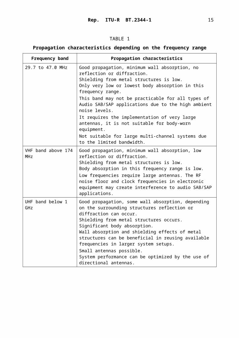
3.1.4 Propagation characteristics of frequency bands
The propagation characteristics for Audio SAB/SAP are shown in the table below depending on the frequency range.
Rep. ITU-R BT.2344-1 11
TABLE 1
Propagation characteristics depending on the frequency range
Frequency band Propagation characteristics
29.7 to 47.0 MHz Good propagation, minimum wall absorption, no reflection or diffraction. Shielding from metal structures is low. Only very low or lowest body absorption in this frequency range.This band may not be practicable for all types of Audio SAB/SAP applications due to the high ambient noise levels.It requires the implementation of very large antennas, it is not suitable for body-worn equipment. Not suitable for large multi-channel systems due to the limited bandwidth.
VHF band above 174 MHz Good propagation, minimum wall absorption, low reflection or diffraction. Shielding from metal structures is low. Body absorption in this frequency range is low.Low frequencies require large antennas. The RF noise floor and clock frequencies in electronic equipment may create interference to audio SAB/SAP applications.
UHF band below 1 GHz Good propagation, some wall absorption, depending on the surrounding structures reflection or diffraction can occur. Shielding from metal structures occurs.Significant body absorption. Wall absorption and shielding effects of metal structures can be beneficial in reusing available frequencies in larger system setups.Small antennas possible. System performance can be optimized by the use of directional antennas.
UHF 1 to 1.7 GHz Acceptable propagation, wall absorption, depending on the surrounding structures reflection or diffraction occurs. Shielding from metal structures occurs.Significant increased body absorption. Wall absorption and shielding effects of metal structures can be beneficial in reusing available frequencies in larger system setups.Small antennas possible. System performance can be optimized by the use of directional antennas.
UHF 1.7 to 2.5 GHz Acceptable propagation, wall absorption, depending on the surrounding structures reflection or diffraction occurs. Shielding from metal structures occurs.Critical body absorption. Wall absorption and shielding effects of metal structures can be beneficial in reusing available frequencies in larger system setups.Small antennas possible. System performance can be optimized by the use of directional antennas.
The UHF band below 1 GHz is the best band for Audio SAB/SAP due to the combination of antenna size, propagation, low body loss absorption and ambient noise floor, especially for body worn equipment.

12 Rep. ITU-R BT.2344-1
3.2 Definitions: analogue, digital and cognitive audio SAB/SAP
3.2.1 Analogue
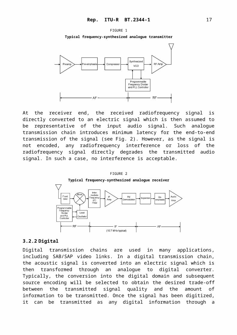
Most current audio SAB/SAP products are based on analogue modulation, e.g. FM modulation. An analogue transmission chain involves the conversion of the acoustic signal into an electric signal which directly drives the radiofrequency signal transmitted over the air (see Fig. 1).
FIGURE 1Typical frequency-synthesized analogue transmitter
At the receiver end, the received radiofrequency signal is directly converted to an electric signal which is then assumed to be representative of the input audio signal. Such analogue transmission chain introduces minimum latency for the end-to-end transmission of the signal (see Fig. 2). However, as the signal is not encoded, any radiofrequency interference or loss of the radiofrequency signal directly degrades the transmitted audio signal. In such a case, no interference is acceptable.
FIGURE 2Typical frequency-synthesized analogue receiver
3.2.2 Digital
Digital transmission chains are used in many applications, including SAB/SAP video links. In a digital transmission chain, the acoustic signal is converted into an electric signal which is then transformed through an analogue to digital converter. Typically, the conversion into the digital domain and subsequent source encoding will be selected to obtain the desired trade-off between the transmitted signal quality and the amount of information to be transmitted. Once the signal has been digitized, it can be transmitted as any digital information through a transmission chain that potentially includes channel/forward error coding, mapping of the channel encoded information to a modulation scheme, digital to analogue conversion of the modulated signal, transmission of the
Rep. ITU-R BT.2344-1 13
radio-frequency signal, analogue to digital conversion of the received signal followed by demodulation and finally decoding of the channel/forward error correcting code.
Such a digital transmission chain may or may not involve a retransmission mechanism in case the packet is not error free at reception.
Typical transmission and reception chains are illustrated in Figs 3 and 4 below.
FIGURE 3Typical frequency-synthesized digital transmitter
FIGURE 4Typical frequency-synthesized digital receiver
3.2.3 Cognitive systems
Interference mitigation in SAB/SAP by cognitive behaviour has been studied both in ETSI STF386 and in a German research project funded by BMWi (German Federal Ministry of Economics and Technology) called C-PMSE. Both activities are aligned as some of the experts are working in both activities.
On 29th of May 2013 a practical demo on cognitive behaviour was given at the Messe Berlin (Berlin Trade Fair center). Initial frequency assignments to SAB/SAP links are calculated, frequency handovers due to raising interference and power control to accommodate a varying link quality were shown to the public. Furthermore it was shown that link quality supervision can be done on analogue FM links in addition to digital systems.
14 Rep. ITU-R BT.2344-1
FIGURE 5Overview of a SAB/SAP cognitive system as considered by the C-PMSE project
The system demonstrated in Berlin and laid out in the output documents of ETSI STF386 is composed of three large subsystems: The Local Spectrum Portfolio Manager, the Scanning system, together reflecting the infrastructure, which may be permanently installed at an event location. Then there is the entire C-PMSE, which is composed out of the two subsystems plus the cognitive engine, which is the intelligence in the system, comprising of a database and the wireless audio links (see Fig. 5).
Signaling with the demo was mapped onto existing short range device air interface standards, which operated in unlicensed bands. This is not an option for real SAB/SAP use as protection is not only needed on the content plane but also on the signaling plane. It also became clear that signaling requires additional spectrum in addition to the spectrum needed for the content plane.
At the Messe Berlin (Berlin Trade Fair center) five halls are equipped with, a total of 30 scanning receivers forming a large scanning grid. The scanning gird is permanently installed and is still in use thus gaining more experience with operating it. It can be accessed remotely by the project partners. For this and other purpose the German research project was extended till end of 2013. Further findings and research results were incorporated in phase C of ETSI STF386 activity.

Rep. ITU-R BT.2344-1 15
3.3 Current state of play
3.3.1 Currently available radio microphones technologies
The vast majority of wireless systems deployed and available in the market are analogue. Frequency modulation has proven to be a very suitable modulation scheme for this application as it allows transmission with minimal latency and is readily implemented. Other desirable characteristics include the fact that FM is a constant envelope modulation scheme and that analogue systems tend to die gracefully in the presence of interference. In addition the “capture ratio” allows reuse of spectrum in adjacent buildings.
While digital microphones have been available for a number of years, they tend to introduce latency which is incompatible with some applications, specifically live performances including IEM. Just recent, since 2013 there have been professional digital microphones systems available. They fulfill the latency criterion and have linear channel spacing.
3.3.2 Factors of the presently available radio microphone and in ear monitor equipment
The significant part of wireless systems deployed and available in the market are still analogue.• Since the introduction of radio microphones (1912) and IEM equipment into the market, up
to today (2015), frequency modulation has proven to be the most suitable modulation scheme for this application as it serves the following requirements:
• A constant envelope modulation scheme allows for long battery life time of the transmitters;
• Due to the evolved technology, the transmitters in the market have a very small form factor, high battery life and a low weight;
• With the demand for more wireless systems to be deployed in a given bandwidth, the spectrum efficiency of analogue radio microphones and IEM has greatly improved;
• The FM “capture ratio” facilitates spectrum reuse even between adjacent venues;• FM systems normally decrease their performance in the presence of interference before
they mute (die gracefully). Most digital systems switch off the link without warning under the same conditions.
Radio microphones have demanding requirements, as they must deliver consistently high audio quality combined with extended constant carrier operation lasting for many hours. In addition a production may have more than 100 radio microphones operating simultaneously in close proximity (less than 2 cm in some cases).
4 Spectrum use of audio SAB/SAP applications for broadcasting
Broadcasting involves into a broad range of applications where all forms of SAB/SAP equipment are used.
4.1 Studio production
Studios use audio SAB/SAP for talkback, microphones and IEM for presenters. The reason for using SAB/SAP equipment with radio links is to give freedom of movement within the studio.
The nature of traditional studio use has changed. In some countries studios that were managed by public broadcasters have now sold off their studio complexes to private organizations. This has resulted in not only the public broadcaster using this studio but intensive use from other programme making companies. This has led to the development of Studio Villages or Media Cities with a

16 Rep. ITU-R BT.2344-1
concentration of facilities in a relatively small physical area. For example 358 audio wireless systems per 1 km2 are being used in Media Park, Hilversum.
The complex frequency environment of these sites requires detailed frequency planning to ensure that no interference is generated between the devices on site.
4.2 News gathering for TV/radio/ internet
Whilst this sector is dealt with in the video section of this Report (see Annex 3), it should be borne in mind that both radio microphones and equipment integral to cameras, including talkback systems will be present at any site. TV news providers use radio links in order to provide rapid response coverage of developing news stories. Therefore video links as well as talkback and radio microphones are used in the production of live and recorded news reports ‘from the scene.
Terrestrial radio links, known under the term of ENG, consist of one or more microwave links that feed video and audio signals directly from the news location to a broadcaster’s network or studio. ENG links are only one of a number of options used to transfer live or recorded material from location to the studio or network, others including:• SNG (satellite news gathering) refers to the use of satellite links to achieve the same thing;• Fibre optic links can be used where a location has a fibre termination;• Store-and-forward over public telecommunications lines can be used for non-live inserts;• Similarly non-live inserts can be recorded digitally and carried by motorbike or otherwise
to the studio.
Each ENG operator (news provider) requires its own exclusive spectrum, for which it requires round-the-clock access over the designated area; there is no scope for event by event co-ordination as the time taken to respond to a news event is too small.
ENG operators normally operate a number of trucks, which can be quickly dispatched to a location where a news event is taking place. The truck contains all the facilities required to cover the story and transmit the signal back to the studio or network for (where necessary or appropriate) further production, editing and/or transmission.
It is estimated that altogether, ENG operators providing news coverage in major conurbations with a high density of news events (typically capital and other big cities, like London, Paris etc.) may require allocation on a city wide basis of up to:• 25-50 talkback narrowband channels;• 15-30 channels for radio microphones;• The video links are further described in Annex 3 on video applications.
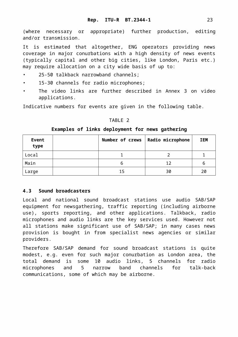
Indicative numbers for events are given in the following table.
TABLE 2
Examples of links deployment for news gathering
Event type Number of crews Radio microphone IEM
Local 1 2 1
Main 6 12 6
Large 15 30 20
Rep. ITU-R BT.2344-1 17
4.3 Sound broadcasters
Local and national sound broadcast stations use audio SAB/SAP equipment for newsgathering, traffic reporting (including airborne use), sports reporting, and other applications. Talkback, radio microphones and audio links are the key services used. However not all stations make significant use of SAB/SAP; in many cases news provision is bought in from specialist news agencies or similar providers.
Therefore SAB/SAP demand for sound broadcast stations is quite modest, e.g. even for such major conurbation as London area, the total demand is some 10 audio links, 5 channels for radio microphones and 5 narrow band channels for talk-back communications, some of which may be airborne.
TABLE 3
Examples of sound broadcast deployment (indicative numbers)
Event type Number of Crews Radio Microphone IEM Audio Links
Local 1 2 1 1
Main 3 6 3 3
Prediction of demand over the next 10 years indicate that the number of channels for audio links and for radio microphones may double, totalling to 15-20 audio link channels and 5-10 radio microphone channels. These are prediction from the broadcaster community [5].
4.4 Regular (sport) events and similar outside broadcasts
All forms of audio SAB/SAP applications are used heavily for sports and other outside broadcasts. Such events have been divided into two sectors. This section covers routine outside broadcasts; the sort of events that occur week in, week out up and down the country. Although co-ordination is needed, difficulties rarely arise and no special planning of frequencies is required. Spectrum does not have to be ‘borrowed’ from other uses to cover events in this section.
Exceptional events such as the Olympic Games occurring each two years 1 require detailed and specialized planning, sometimes on-the-ground co-ordination, and ‘borrowing’ of spectrum from other uses.
The distinction should be emphasized that there are many more regular events than major events. Therefore it would not be desirable to have to expend the same planning effort that goes into the large events on the events in this section, unless there were clear rewards in terms of spectral efficiency.
However it should be obvious that if there is more than one broadcaster covering an event or if several events occur in the same geographical area, then the above estimates should be multiplied by the number of broadcasters. Demand may also increase if it becomes necessary to duplicate some of the links, or use repeaters, etc. for topography or other reasons.
1 Considering both the summer and winter Olympic Games.

18 Rep. ITU-R BT.2344-1
5 Frequency bands for audio SAB/SAP applications in CEPT
During the development of a Report on SAB/SAP in CEPT countries a questionnaire was sent to administrations on the regulatory procedures used by administrations in granting access to spectrum for audio SAB/SAP applications [2].
The questionnaire covered all frequency bands that are available for audio SAB/SAP applications. The table below summarizes the results – based on the replies of 34 CEPT administrations – relevant for audio SAB/SAP applications regarding availability and use.
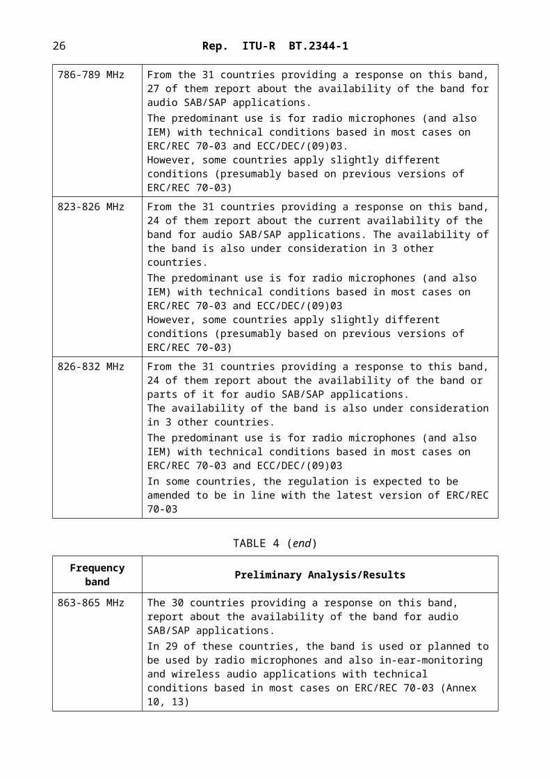
TABLE 4
Results of CEPT questionnaire on the availability of spectrum for audio SAB/SAP applications
Frequency band Preliminary Analysis/Results
29.7-47.0 MHz The summary shows that this band, fully or part of it, is widely available for audio SAB/SAP applications across CEPT (25 from the 30 providing a response to this band). This is mostly for radio microphones, sometimes with the extension to other low power audio applications
174-216 MHz From the 30 administrations providing a response on this band, 28 reports about the availability of the band or parts of it for audio SAB/SAP applications. Predominant use is for radio microphones (including hearing aids); the band is also used for other audio SAB/SAP applications such as wireless audio links and talkbacks with technical conditions based in most cases on ERC/REC 70-03 [7]. However, some countries apply more stringent conditions (lower e.r.p. or requirement on the bandwidth or channel spacing)
470-786 MHz From the 31 countries providing a response on this band, 29 reports about the availability of the band or parts of it for audio SAB/SAP applications. Predominant use is for radio microphones (and also IEM) with technical conditions based in most cases on ERC/REC 70-03
786-789 MHz From the 31 countries providing a response on this band, 27 of them report about the availability of the band for audio SAB/SAP applications.The predominant use is for radio microphones (and also IEM) with technical conditions based in most cases on ERC/REC 70-03 and ECC/DEC/(09)03. However, some countries apply slightly different conditions (presumably based on previous versions of ERC/REC 70-03)
823-826 MHz From the 31 countries providing a response on this band, 24 of them report about the current availability of the band for audio SAB/SAP applications. The availability of the band is also under consideration in 3 other countries.The predominant use is for radio microphones (and also IEM) with technical conditions based in most cases on ERC/REC 70-03 and ECC/DEC/(09)03However, some countries apply slightly different conditions (presumably based on previous versions of ERC/REC 70-03)
826-832 MHz From the 31 countries providing a response to this band, 24 of them report about the availability of the band or parts of it for audio SAB/SAP applications. The availability of the band is also under consideration in 3 other countries. The predominant use is for radio microphones (and also IEM) with technical conditions based in most cases on ERC/REC 70-03 and ECC/DEC/(09)03In some countries, the regulation is expected to be amended to be in line with the latest version of ERC/REC 70-03
Rep. ITU-R BT.2344-1 19
TABLE 4 (end)
Frequency band Preliminary Analysis/Results
863-865 MHz The 30 countries providing a response on this band, report about the availability of the band for audio SAB/SAP applications.In 29 of these countries, the band is used or planned to be used by radio microphones and also in-ear-monitoring and wireless audio applications with technical conditions based in most cases on ERC/REC 70-03 (Annex 10, 13)
1785-1800 MHz From the 30 countries providing a response on this band, 23 of them report about the availability of the band or parts of it for audio SAB/SAP applications. In addition, 3 countries intend to make the band available in the near future.The band is used or planned to be used by radio microphones and also IEM and wireless audio applications with technical conditions based in most cases on ERC/REC 70-03 (Annex 10, 13)
From the analysis and results of the responses to the audio SAB/SAP questionnaire, it can be concluded that there are 8 tuning ranges currently available for SAB/SAP audio applications in the majority of the countries from which responses were received. The actual availability of certain frequencies at a given geographical location depends also on the use of other (primary) services.
Operating and/or usage restrictions in a given tuning range may result from other services working in the same or adjacent band as the audio SAB/SAP applications. In addition the propagation conditions discussed in § 3.1.4 play a large part on the usability of the band and on the type of Audio SAB/SAP applications which could be used in a given band.
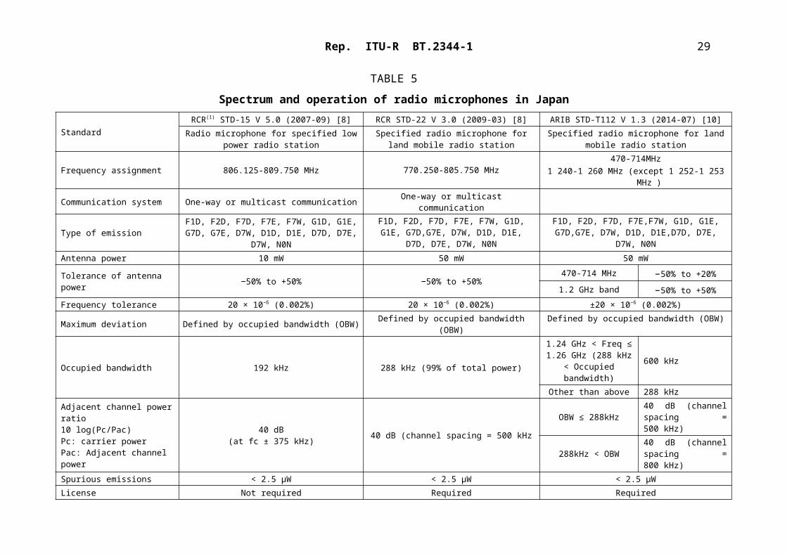
6 Spectrum and operation of radio microphones and planning for digital radio microphones in Japan
6.1 Spectrum and operation of radio microphonesIn Japan, the 70 MHz band (74.58-74.76 MHz), the 300 MHz band (322.025-322.400 MHz), and the 800 MHz band (806.125-809.750 MHz) were assigned to radio microphones for low power radio station, for which a license is not required. Also, 779.125-787.875 MHz and 797.125-805.875 MHz were assigned to radio microphones for professional use, for which a license is required.
In 2011, the band 710-806 MHz was reassigned to commercial mobile phone and other applications. In consequence, 470-714 MHz, 1 240-1 260 MHz (except 1 252-1 253 MHz) were newly assigned to radio microphones. In the band 470-710 MHz radio microphone applications are shared with digital terrestrial-broadcasting as a second basis. The frequency reassignment should be completed by March 2019. System parameters for radio microphones are shown in Table 5.

20 Rep. ITU-R BT.2344-1
TABLE 5
Spectrum and operation of radio microphones in Japan
StandardRCR(1) STD-15 V 5.0 (2007-09) [8] RCR STD-22 V 3.0 (2009-03) [8] ARIB STD-T112 V 1.3 (2014-07) [10]Radio microphone for specified low
power radio stationSpecified radio microphone for
land mobile radio stationSpecified radio microphone for land mobile radio
station
Frequency assignment 806.125-809.750 MHz 770.250-805.750 MHz 470-714MHz1 240-1 260 MHz (except 1 252-1 253 MHz )
Communication system One-way or multicast communication One-way or multicast communication
Type of emission F1D, F2D, F7D, F7E, F7W, G1D, G1E, G7D, G7E, D7W, D1D, D1E, D7D, D7E, D7W, N0N
F1D, F2D, F7D, F7E, F7W, G1D, G1E, G7D,G7E, D7W, D1D, D1E, D7D, D7E, D7W,
N0N
F1D, F2D, F7D, F7E,F7W, G1D, G1E, G7D,G7E, D7W, D1D, D1E,D7D, D7E, D7W, N0N
Antenna power 10 mW 50 mW 50 mW
Tolerance of antenna power −50% to +50% −50% to +50%470-714 MHz –50% to +20%1.2 GHz band –50% to +50%
Frequency tolerance 20 × 10–6 (0.002%) 20 × 10–6 (0.002%) ±20 × 10–6 (0.002%)Maximum deviation Defined by occupied bandwidth (OBW) Defined by occupied bandwidth (OBW) Defined by occupied bandwidth (OBW)
Occupied bandwidth 192 kHz 288 kHz (99% of total power)
1.24 GHz < Freq ≤ 1.26 GHz (288 kHz < Occupied bandwidth)
600 kHz
Other than above 288 kHzAdjacent channel power ratio 10 log(Pc/Pac)Pc: carrier powerPac: Adjacent channel power
40 dB(at fc ± 375 kHz) 40 dB (channel spacing = 500 kHz
OBW ≤ 288kHz 40 dB (channel spacing = 500 kHz)
288kHz < OBW 40 dB (channel spacing = 800 kHz)
Spurious emissions < 2.5 µW < 2.5 µW < 2.5 µWLicense Not required Required RequiredCollision avoidance between users Not coordinated Coordinated Coordinated

Rep. ITU-R BT.2344-1 21TABLE 6
Further information regarding the spectrum and operation of radio microphones in Japan
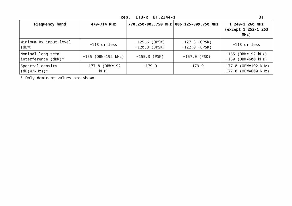
Frequency band 470-714 MHz 770.250-805.750 MHz 806.125-809.750 MHz 1 240-1 260 MHz(except 1 252-1 253 MHz)
Antenna type and gain Non-directional (2 dBi)
Modulation
QPSK8PSK
QPSK-OFDM16QAM-OFDM
QPSK8PSK
QPSK8PSK
QPSK8PSK
QPSK-OFDM16QAM-OFDM
Maximum capacity (kbit/s) 576 128 128 1248Channel spacing (kHz) 25 125 250 25
Feeder/multiplexer loss (typical) (dB) Tx 0Rx 1
Tx 0Rx 1
Tx 0Rx 1
Tx 0Rx 1
Maximum antenna input power (dBW) −13 −13 −20 −13
e.i.r.p. (maximum) (dBW) −11 −11 −18 −11
Occupied bandwidth (kHz) 192, 288 288 192 192, 288192, 288, 600 (OFDM)
Receiver noise figure (dB) 6 6 6 6
Receiver thermal noise (dBW)* −145 (OBW=192 kHz) −145.3 (QPSK, 8PSK) −147.0 (QPSK, 8PSK) −145 (OBW=192 kHz)−140 (OBW=600 kHz)
Minimum Rx input level (dBW) −113 or less −125.6 (QPSK)−120.3 (8PSK)
−127.3 (QPSK)−122.0 (8PSK) −113 or less
Nominal long term interference (dBW)* −155 (OBW=192 kHz) −155.3 (PSK) −157.0 (PSK) −155 (OBW=192 kHz)
−150 (OBW=600 kHz)
Spectral density (dB(W/kHz))* −177.8 (OBW=192 kHz) −179.9 −179.9 −177.8 (OBW=192 kHz)−177.8 (OBW=600 kHz)
* Only dominant values are shown.

22 Rep. ITU-R BT.2344-1
7 Future developments related to audio SAB/SAP applications
7.1 Considerations on future perspectives for audio SAB/SAP applications
Developments in the film, TV and theatre world are requiring ever increasing sound quality and density of radio microphones this is coupled with increased usage of both radio microphones and IEM in all forms of multimedia platforms resulting in a conundrum of reducing spectrum availability and higher performance.
Higher contribution quality on the production side is required for the new 24 bit, 96 kHz “Pure Audio on Blue Ray” Audio Format set by production companies such as DECCA, Deutsche Grammophon and others. These “Pure Audio Blue Ray” Discs are already in the market place and the music industry has set this as future standard. This process is implemented first in classical music – classic live is one branch in the audio industry that is growing and demands higher audio quality – and other genres will follow.
The higher audio resolution that is given by the “Pure Audio Blue Ray” gains the audio resolution especially in the mid and higher frequencies. This will give more detailed facets of the instruments used and enhances the listener’s experience.
7.2 Future challenges
7.2.1 Highest quality
Compression in any form, including dynamic compression, is not desirable during the contribution phase as compression always means losses for the subsequent reproduction.
For highest quality applications it is required to produce loss-less audio, without compression – with full dynamic range. This production material will be available in highest quality for the distribution via, TV SD/HD, CD, DVD; Blue Ray, etc. and future formats can use this recording as the high quality of the original production can be transferred to any future format.
This is the real challenge for wireless vocal, instrument and atmosphere/environment microphones. This leads to higher channel audio SAB/SAP bandwidth and increases spectrum demand in order to increase quality to adapt to industry needs and expand the listening experience.
7.2.2 Increased dynamic
Many of the current Audio SAB/SAP equipment are limited in their dynamic range. Because of this, adjustments have to be made individually for each audio SAB/SAP link in a setup to secure the highest possible audio quality. Usually during rehearsal the sensitivity of the microphone connected to the transmitter will be manually adjusted. The settings are done in a way that headroom of about 10 dB is given before the internal limiter of the transmitter cuts the signal. If the user of the radio microphone exceeds this headroom of 10 dB internal limiter starts working: this will be audible and reduces the perceived quality. This may happen depending on the kind of performance and the engagement of the user. The problem is the limitation in the available dynamic range that current systems are able to handle. This would need to be increased in order to give the sound engineer the full dynamic range of the of the microphone capsule to his mixing console: at the mixing console the sound engineer will adjust the dynamics in a way that it fits to the rest of the production.
For wired operations, studios have already 24 to 48 bit audio resolution. Present wireless audio equipment in 200 kHz channel bandwidth cannot support these requirements.

Rep. ITU-R BT.2344-1 23
7.3 New RF bandwidth
ETSI EN 300 422 [11] standard has different RF bandwidths of 200, 400 and 600 kHz. Today, most of the Audio SAB/SAP equipment uses a 200 kHz bandwidth, however, the introduction of systems using larger bandwidths is necessary for certain applications in order to accommodate an increase in the audio quality to meet the requirements this may result in an increase in terms of spectrum demand.
7.4 Future technologies
A number of attempts have been made to harness the new mobile technologies and other systems for radio microphone use; however all have so far failed primarily on the latency issues. Networks latencies which were achieved during those attempts far exceeds the 3-4 ms (see ITU-R Report BS.2161 [4]) required to ensure lip synchronization at the front end of a production chain based on the current technology of Audio SAB/SAP.
Reviewing the information available when developing this Report (September 2014) on future technologies and modulation schemes from CEPT, ETSI and ITU none appear to offer any practical alternatives to the current radio microphone technologies being developed by manufacturers.
Currently semi cognitive analogue and digital systems are available. Dependent on the outcome of the C-PMSE project fully cognitive systems will be developed but given the complexity of both hardware and software the timescales for initial deployment and then significant market penetration are several years in the future.

24 Rep. ITU-R BT.2344-1
Attachment 1 to Annex 2
Supplementary information on technical SAB/SAP characteristics
Radio microphones normally use wide band frequency modulation to achieve the necessary audio performance for professional use. For the majority of applications the transmitted signal requires a channel bandwidth of up to 200 kHz, but may be up to 600 kHz to support HD sound. IEM equipment is used by stage and studio performers to receive personal fold back (monitoring) of the performance. This can be just the own voice or a complex mix of sources. The bandwidth requirement of professional IEM equipment is 200 kHz.
The comparison of different specifications and operational requirements of radio microphones, IEM and audio links is given in Table 7 below.
TABLE 7
Comparison of Radio microphones in-ear-monitors and Audio Links
Characteristics Radio microphones IEM Audio links
Application Voice (speech, song), Music instruments
Voice or mixed feedback to stage
ENG/OB , voice
Transmitter
Placement of a transmitter
Body worn or handheld Fixed base Body worn/vehicle mounted
Power source Battery AC mains Battery
Transmitter RF-Output power
Below 50 mW Below 50 mW Above 50 mW up to below 25W
Transmitter audio input
Microphone or line level Line level Microphone or line level
Receiver
Placement of a receiver
Fixed/Camera mounted Body worn Fixed/vehicle mounted
Power Source AC mains/Battery Battery AC mains/Battery
Receiver audio output
Line level Earphone Line level/Earphone
Receiver type Single or diversity Single or diversity Single or diversity
General
Link scheme Unidirectional Unidirectional BidirectionalPlus talk back channel
Battery/power pack operation time
6-10 h 6-10 h 6-10 h
Rep. ITU-R BT.2344-1 25
TABLE 7 (end)
Characteristics Radio microphones IEM Audio links
Typical Audio frequency response
≤20 to ≥20.000 Hz ≤80 to ≥15.000 Hz Link to base: ≤20 to ≥20.000 HzFold back to mobile unit: 12.5 kHz
Audio mode Mono MPX-Stereo 2 way Mono
RF frequency ranges
TV bands III/IV/V, 1.8 GHz (Note)
TV bands III/IV/V, 1.8 GHz (Note)
TV Bands I/ III/IV/V, 1.8 GHz
Dynamic range of the RF link
117 dB Typical 90 dB 115 dBTalk back link: lower
Typical minimum sensitivity
−90 dBm −85 dBm
Modulation FM wideband as well proprietary digital modulation
FM wideband as well proprietary digital modulation
FM wideband as well proprietary digital modulationTalkback link: FM narrow
RF peak deviation (AF = 1 kHz)
±50 kHz ±50 kHz ±50 kHzTalkback link: voice quality
RF bandwidth ≤200 kHz standard quality
≤600 kHz HD sound quality
≤300 kHz legacy equipment≤200 kHz modern equipment
2 times <200 kHzplus 12.5 kHz
Useable equipment/channel (ΔRF = 8 MHz)
>12 6…8 Not applicable
Audio dynamic(currently/required for HD sound)
>100/>>119 dB (20 bit) to 145 (24 bit)
>60/110 dB >100/>>119 dB (20 bit)Talk back link: lower
NOTE – Radio microphones and IEM may be also used in 863-865 MHz if complying with either EN 301 357 [12] or EN 300 422 [11] (10 mW).
Spectrum mask
This gives the following spectrum masks for analogue systems or for digital systems.

26 Rep. ITU-R BT.2344-1
FIGURE 6Spectrum mask for analogue systems
NOTES:• The Reference power is to be measured at the unmodulated carrier centre frequency (fc).• The −90 dBc point shall be at ±1 MHz from fc measured with an average detector. To comply, a
measured value must fall below the mask limit as shown above.
FIGURE 7Spectrum mask for digital systems
B
fc + 0,35B fc - 0,35B
0dB
-10
-30
-40
-50
-60
-70
-80
-90
-100
Unmodulated carrier reference
fc - 1 MHz fc - B fc - B _ 2
B _ 2
fc fc + fc + B fc + 1 MHz
fc = Transmitter carrier frequency
-20

Rep. ITU-R BT.2344-1 27
NOTE – The −90 dBc point shall be ±5*B from fc measured with an average detector(example 1 MHz if B=200 kHz).
Frequency error
The frequency error shall not exceed 20 parts per million for frequencies below 1 GHz, 15 parts per million between 1 GHz and 2 GHz and 10 ppm above 2 GHz.
Spurious emissions limits at transceiver antenna port
TABLE 8
Spurious emission limits at transceiver antenna port
State Frequency
47 MHz to 74 MHz87.5 MHz to 137 MHz174 MHz to 230 MHz470 MHz to 862 MHz
Other Frequenciesbelow 1 000 MHz
Frequencies above1 000 MHz
Operation 4 nW 250 nW 1 µWStandby 2 nW 2 nW 20 nW
Measured values for equipment in each frequency band must be below the values given in Table 8 above.
Minimum required audio quality
The minimum required audio quality for a radio microphone link as the unwanted signal level which degrades the microphone receiver output audio S+N/N to 80 dB(A) or a SINAD of 30 dB.
Propagation issues
This section presents some information to the typical transmission path from the transmitter to receiver units.
FIGURE 8Measurements of an antenna radiation patterns
28 Rep. ITU-R BT.2344-1
Transmission path loss: worst case scenario
Path loss for a radio microphone transmission is often interpreted as a simple line of sight scenario; however this is rarely the case as the figures below show:
Components of microphone transmission path can be described as:• Microphone output power (ERP) 17 dBm• PLFS – Free space path loss 32.44+20*log10(D/1000)+20*log10(F)• PLALD – Microphone antenna loss & detuning effect up to 15 dB• PLB – Loss effected while carrying antenna on human body (average) up to 25 dB2
• PLN – Additional loss in the transmission path notches (non-diversity) up to 30 dB• PGDV – Gain by using antenna diversity techniques up to 7 dB• PGA – Gain through receiver antenna typical 7 dB
The worst case in a typical non-diversity installation can described as:
Total Loss Worst Case ND (dB) = PLFS + PLALD + PLB + PLN – PGA
Change in path loss using a diversity antenna system
Typical SAB/SAP antenna diversity systems use two antennae with the same characteristics that are physical separated (Spatial diversity). In some configuration, the SAB/SAP combines pairs of antennas with orthogonal or circular polarizations. Because of the linear microphone polarization this should not be misinterpreted as polarization diversity.
The worst case in a typical installation by using diversity receiver antennas can described as:
Total loss worst case D (dB) = PLFS + PLALD + PLB + PLN – PGDV – PGA
Diversity receivers using two antennas and a signal switching system vary in their effectiveness depending on the spacing and type of antenna in use.
Figure 9 shows the complex situation on the transmission path if all parameter considered.
FIGURE 9
NOTES: • The red and blue lines represent the reception level at the antennas.
2 The value varies between 20 and 40 dB.
Microphone Distance [m]
Rec
eive
r Inp
ut L
evel
[dB
m]
-90
-80
-70
-60
-50
-40
-30
-20
Microphone Distance [m]10
Simulated Receiver Input Signal [dBm] in a Diversity Antenna System Typical level on 1st antennaTypical level on 2nd antennaDiversity antenna outputFree space path levelApplication level limitWorst case level

Rep. ITU-R BT.2344-1 29
• The green line is the best-case signal provides by the diversity algorithm. The diversity cannot eliminate all path notches but can reduce their effect.
Link budget
In addition to the path loss there are additional interference problems on a microphone path, which affects the system performance (e.g. Interference, Man Made Noise, antennas placed in actor costume or stage installations). For any production there may be a range of link budgets dependant on the relative locations of the radio microphone user and the receive antenna. Fading, where the actor moves behind scenery is a constant problem and can be up to 40 dB.
Typical link budget calculation using a diversity antenna system.
Input Parameter
D – Distance 20 m
F – Frequency 700 MHz
RXCH – Microphone receiver channel bandwidth 1.40E+05 Hz
Pout – Microphone output power (ERP) 17 dBm
PLALD – Microphone antenna loss & detuning effect 15.0 dB
PLB – Loss effected while carrying antenna on human body 25.0 dB
PLN – Additional loss in the transmission path notches 30.0 dB
PGDV – Gain by using antenna diversity techniques 7.0 dB
PGA – Gain through receiver antenna 7.0 dB
RNF – Receiver noise figure 8.0 dB
RMINSNR – Receiver minimum SNR 20.0 dB
Constant Parameter
TNF – Thermal noise floor 1 Hz bandwidth at 20 °C −174.0 dBm
Calculation
PLFS – Free space path loss using 0 dB dipole antennas
32.44+20*log10(D/1000)+20*log10(F) 55.4 dB
TPF – Total path los PLFS + PLALD + PLB + PLN – PGDV – PGA
111.4 dB
RTNF – Thermal noise floor at receiver channel bandwidth at 20°C −122.5 dBm
TRF – Total receiver noise power RTNF + RNF −114.5 dBmRMINRINP – Minimal needed receiver input signal TRF + RMINSNR −94.5 dBmRINPS – Receiver input signal POUT – TPF −94.4 dBm
Link budget RMINRIN – RINP 0.2 dB
NOTE: • A link budget grater than 0 shows the physical link feasibility in absence of interfernce.• Any additional interfernce leads to a reduction in the practical link distance.

30 Rep. ITU-R BT.2344-1
Short form presentation of signal level and path losses
Pout – Microphone output power (ERP) 17.0 dBm
PLALD – Microphone antenna loss & detuning effect −15.0 dB
PLB – Loss effected while carrying antenna on human body −25.0 dB
PLN – Additional loss in the transmission path notches −30.0 dB
PGDV – Gain by using antenna diversity techniques 7.0 dB
PGA – Gain through receiver antenna 7.0 dB
RNF – Receiver noise figure −8.0 dB
RMINSNR – Receiver minimum SNR −20.0 dB
PLFS – Free space path loss using 0 dB dipole antennas −55.4 dB
RTNF – Thermal noise floor at receiver channel bandwidth −122.4 dBm
Illustrative example of interference in to the audio receiver unit of a SAB/SAP system and compatibility figures
Minimal required C/I for microphone links in the presence of a wideband interferer
This lab test example shows a test LTE signal (2) and an audio SAB/SAP measuring signal (1) at a measurement bandwidth of 100 kHz. To ensure the minimum necessary production quality, the useful carrier to interference ratio (C/I) can be determined from the difference between the LTE (2) and audio SAB/SAP (1) signal strengths. Monitoring and control was achieved by means of a headset.
Figure 10 shows the test scenario RF spectrum.
Rep. ITU-R BT.2344-1 31
FIGURE 10Test scenario RF spectrum
As shown in Fig. 10 the 1 kHz audio test signal was interference free with a C/I value of ~ 22 dB. This confirms the initial hypothesis that a minimal C/I of 20 dB is needed for analogue microphone use.Wideband transmitter in adjacent spectrum
Figure 11 shows the signals of six radio microphones.

32 Rep. ITU-R BT.2344-1
FIGURE 11Six Microphone Signals (Illustration)
The SNR at receiver input is set according to the result of the link budget calculation.
Figure 12 shows a wideband interferer adjacent to the microphone channel.
FIGURE 12Wideband interferer adjacent to the microphone channel (Illustration)
The adjacent channel transmitter noise will block all microphone links completely.
Frequency (MHz)
Rece
iver i
npui
t sig
nal (
dBm
)
-130
-110
-90
-70
-50
Frequency (MHz)710 716 722 728 734 740
6 SAB/SAP Signals @ Receiver Input
Frequency (MHz)
Rece
iver i
npui
t sig
nal (
dBm
)
-130
-110
-90
-70
-50
Frequency (MHz)710 716 722 728 734 740
Six SAB/SAP Signals and one Wide Band Source
Thermal noise level
Microphones
Rep. ITU-R BT.2344-1 33
Figure 13 shows the microphone channel in middle of wideband interferers.
FIGURE 13Microphone channel in middle of wideband interferers (Illustration)
All microphone channels are completely blocked.NOTE: • The signal quality of adjacent wideband transmitter defines the neighbouring risk to SAB/SAP.• Possible blocking effects are not considered.
Figure 14 shows the signal scenario on a different way.
Frequency (MHz)
Rece
iver i
npui
t sig
nal (
dBm
)
-130
-110
-90
-70
-50
Frequency (MHz)710 716 722 728 734 740
Six SAB/SAP Signals in between of Wide Band Sources

34 Rep. ITU-R BT.2344-1
FIGURE 14
Interference free microphone scenario Interfered microphone links
NOTE – Each colour presents a different signal
Active antenna distribution systems
Many use scenarios will require additional components in the path from transmitter output to receiver input that affect the interference scenario.
Receiver distribution system
In a simple environment, each receiver has its own antenna. A large production would therefore require 50 or more antennas, which is impractical. Therefore, the professional event uses antenna distribution systems. The signal of a single receiving antenna are split into many receiver paths, this unamplified antenna power division results in additional losses from antenna to receiver port. An antenna amplifier can compensate for this signal loss but the antenna amplifier is a nonlinear and broadband device. Nonlinearity in combination with high-bandwidth (e.g. 24 to 100 MHz) degrades the desired receiver performance. The receiver is affected by interference from the intermodulation generated within the amplifier.
Additional filters are used to provide protection from other radio signals.
Non linearity of an antenna distribution amplifier
A typical antenna amplifier was measured for its linear transfer function (Fig. 15).
FIGURE 15
Frequency (MHz)
Rec
eive
r inpu
it si
gnal
(dB
m)
-120
-110
-100
-90
-80
-70
-60
-50
-40
-30
-20
-10
Frequency (MHz)810 811.5 813 814.5 816 817.5 819 820.5 822 823.5 825
PMSE Receiver Input Signal
Frequency (MHz)R
ecei
ver in
puit
sign
al (d
Bm)
-120
-110
-100
-90
-80
-70
-60
-50
-40
-30
-20
-10
Frequency (MHz)810 811.5 813 814.5 816 817.5 819 820.5 822 823.5 825
PMSE Receiver Input Signal
Power (dBm)
Fund
amen
tal O
utpu
t Pow
er (d
Bm)
-10
0
10
20
Power (dBm)-23 -21 -19 -17 -15 -13 -11 -9 -7 -5 -3 -1 1 3 5 7
Amplifier Input to Output Power Performance (measured)
Fundamental Output Power
Rep. ITU-R BT.2344-1 35
NOTE – The dotted blue line shows the linear admittance function.
Transmitter distribution system
IEMs use a fixed transmitter mounted in “19” racks, and it is impractical to use individual antenna in a large system Therefore transmitter outputs are combined to a common antenna path. Once again, the power losses are compensated by use of an amplifier. Nonlinearity in combination with high-bandwidth degrades the desired transceiver performance. The combined transmitter spectrum on antenna output is filled with IM products.
Additional filters are used to provide protection to other radio application outside the microphone band.
Intermodulation and reverse intermodulation
Radio microphones and IEM are unusual in the radio world in that large numbers of transmitters (in excess of 80 at a large show); operate simultaneously for a number of hours and in very close proximity, in many cases within centimetres of each other.
It should be borne in mind that all radio microphones and IEMs will be switched on prior to the start of a performance and not switched off until the audio or recording system is shut down to prevent clicks and bangs being sent to the audio amplification or recording system.
Intermodulation
Intermodulation occurs when two or more radio signals combine together. In radio microphone and In Ear Monitor applications this is a critical consideration.
Radio microphones and IEMs are typically wideband FM systems, although radio microphone systems using digital technology do exist. Contrary to popular belief the digital systems are not completely immune to problems with intermodulation but the way in which they are affected is different from their analogue counterparts. For the most part we will deal with analogue systems here since they represent both the majority in current usage and the bulk of the equipment currently available on the market.
Intermodulation can occur anywhere in the radio system, • in the transmitter;• in the receiver;• in ancillary RF equipment or in the environment.
Manufacturers can control the contribution that each element of their equipment makes to a large extent and significant differences in performance exist between different brands and models of SAB/SAP equipment in respect of the levels of intermodulation produced and the levels of tolerance they have to intermodulation interference. However, since intermodulation can also occur elsewhere than within the radio microphone equipment it cannot be completely eliminated and therefore the best possible mitigation is to avoid the consequences of interference from any possible intermodulation wherever possible. Once an intermodulation product exists in the environment, regardless of how it originates, it is just another interference source and the effect that it will have on a receiver can be predicted to a large extent by reference to the C/I performance of the receiver.
The number of intermodulation products present rises exponentially as the number of carriers’ increases. Consequently the number of clean frequencies available within a given bandwidth declines rapidly as the number of carriers increases. The strength of the received signal from a radio microphone at the receiving antenna(s) varies widely as the transmitter moves around. Frequently the strength of the ‘wanted’ signal at the receiver will be less than that of one or more unwanted

36 Rep. ITU-R BT.2344-1
signals on adjacent frequencies, be they signals from other radio microphone transmitters which are in more favourable locations than the source of the ‘wanted’ signal, or intermodulation products.
In practice it is frequently the case that the wanted radio mix signal is one of the weakest at the receiving antennas since during many types of event at various times a single performer or group of performers may be on stage and therefore at a distance from the receiving antennas when the remainder of a shows cast are off stage and therefore their transmitters are closer to the receiving antennas.
Since intermodulation must exist at some point in all radio communications systems where there are multiple simultaneous transmissions many RF practitioners are often puzzled as to why it is such a major preoccupation for those involved in SAB/SAP. To understand this one needs an appreciation of the circumstances in which intermodulation becomes the problem. In the majority of communications systems either only voice quality (300-3 400 Hz) or data with check algorithms are in use. For SAB/SAP two major contributors are the wide audio bandwidth and wide audio dynamic range (or audio signal to noise ratio) of radio microphones and IEMs. Radio microphones typically have audio frequency responses ranging from 20 Hz up to 20 kHz and signal to noise ratios exceeding 100 dB. Consequently a low level heterodyne that might present no problem and even go completely unnoticed in other types of radio communications will be considered harmful interference in SAB/SAP applications (e.g. a 12.5 kHz heterodyne which demodulates as a whistle at −40 dB will not be apparent in a PMR system since it will be outside the audio frequency range and also close to the audio noise floor but it will be very obvious in a radio microphone system). Since radio microphones are at the start of the audio production chain any interference at this point affects the entire downstream audience. Since in practice the likely sources of the signals which have combined to produce a particular intermodulation product will themselves be carrying modulation the intermodulation product will also carry a combination of the contributors modulation, more often than not this makes it even more audibly obtrusive. The ultimate audio output of an event, whether broadcast, recorded or live will frequently also be a combination of the audio output from more than one radio microphone summed together and so will contain the sum of any interference experienced by those radio microphones.
The problems can be exacerbated in IEM systems by a number of factors. When operated in Stereo mode – the default for Live Music performers – the demodulated bandwidth of the IEM receiver is necessarily considerably larger than for a mono radio microphone (or an IEM receiver operating in Mono mode). The operation of the multiplex stereo system using a 38 kHz sub carrier to carry the L-R difference information means that the receiver is susceptible to disturbance by interference that demodulates as baseband frequencies up to at least 53 kHz which are then rendered audible by the multiplex decoding process. In live music use the IEM receiver feeds high performance audio transducers inserted in to the ear canal of the artist’s ears, consequently the smallest disturbance is conducted directly to the performer’s ears which at the very least can be distracting for them and far more serious in the case of severe interference. Additionally IEM receivers are necessarily small battery powered devices and consequently are restricted in terms of antenna, space and energy resources which in turn can restrict their RF performance in comparison with what can be achieved by a top-of-the-range mains powered rack mounted radio mic receiver. Until quite recently IEM receivers did not feature diversity reception, although newer models do now benefit from this technology.
Reverse intermodulation
The term reverse intermodulation describes the situation that occurs when RF enters the output of an RF amplifier such as the output stage of a transmitter where other signals in the ‘ether’ are received via the transmitting antenna. Since the output is not designed to deal with signals being presented in this way mixing occurs between the ‘received’ signals and also the signal that the

Rep. ITU-R BT.2344-1 37
amplifier is amplifying. In general the more linear the amplifier the less reverse intermodulation will occur, up to a point. If the ‘received’ signals are sufficiently large then overload will occur. In a small battery powered device designed to output only a few tens of milliwatts this is quite a realistic proposition in the presence of higher powered transmitting devices particularly if they are operating in or near the same frequency band.
Mitigation techniques
In permanent base station installations there are a number of standard practice techniques that are commonly used which reduce intermodulation between multiple co-sited transmitters. A transmitter which is going to operate long term on a single frequency can have output filters, either internally or applied separately as part of the installation, these filters may be multi pole and have a high Q and these can contribute considerably to the reverse intermodulation performance. Ferrite isolators or circulators commonly used to combine transmitter outputs or to protect transmitters against antenna damage also produce dramatic improvements in reverse intermodulation performance at base station sites. Even antenna feeder cable loss has a beneficial effect in reducing the generation of reverse intermodulation products since it attenuates both the ‘received’ contributors travelling from the antenna to the transmitter output and also the resulting intermodulation products on their way back to the antenna.
Unfortunately most of these techniques are not suitable for small portable battery powered devices with a wide tuning range such as radio microphones. Each contributes weight, size, reduced efficiency or a combination of all three. Highly selective filters band pass filters in radio microphone transmitter output stages were once common in high end professional devices when they operated on a single crystal controlled frequency (>20 years ago). The need for more frequency agile devices with wider tuning ranges means that modern equipment has to take a different approach with wider pass band filtering and linear output amplifiers instead. Miniature ferrite isolators do exist but have limited bandwidth thus limiting the tuning range of any equipment in to which they are incorporated and they also add size and weight which are both undesirable. A simple attenuator between the transmitter output and the antenna can deliver reverse intermodulation performance improvements without imposing significant weight or size penalties, but the effect on efficiency and therefore battery life are readily apparent and therefore not necessarily desirable.
Frequency planning
Since ultimately intermodulation cannot be completely prevented or controlled, the solution adopted by the SAB/SAP industry is to plan frequency usage so as to avoid the predictable consequences of interference which would result from intermodulation as far as is reasonably possible.
If a number of carriers are evenly spaced in frequency then mutual interference due to intermodulation can be predicted. If just three carriers are each spaced evenly then two of the three carriers will be vulnerable to interference from 3rd order two tone intermodulation products.
For ten, evenly spaced, carriers the number of two tone 3rd order products which will occur directly on the carrier frequencies is forty, evenly distributed at four per carrier frequency. If we start to look at higher order intermodulation products and higher numbers of tones, although the products will individually be predictably smaller in signal strength, they will be more numerous in quantity and the cumulative effect cannot be ignored in systems with multiple transmitters. So far we have only considered the carrier frequency and assumed zero bandwidth. Once we enter the real world then we have to consider the situation where any intermodulation products which occur within the receiver channel bandwidth can also be a source of interference. How far in frequency from the carrier frequency an intermodulation product can be before it can be ignored is a major differentiator between different brands and models of SAB/SAP equipment. For many events and

38 Rep. ITU-R BT.2344-1
locations where SAB/SAP equipment is present there may be a mixture of makes and models of equipment in use which further complicates the frequency planning. In a multiple channel system using frequency spacing which is equal to the channel spacing plus a fraction of channel spacing will still result in intermodulation products which are within the channel bandwidth. As a simple rule of thumb the spacing between any two frequencies in a system must be different to that between any other pair of frequencies.
Intermodulation products vs required bandwidth
If the TX frequencies of the transmitters are equally spaced within a given bandwidth, virtually the required bandwidth for the transmitter setup is low, but the RF noise generated through the intermodulation products in the vicinity of the carriers increases significantly and makes the RF channels adjacent to the TX carriers unusable.
FIGURE 16Generated intermodulation products for 8 equally spaced transmitter carriers
In real world situations, the maximum number of IM free channels will depend on the quality of the links as well as the equipment use. The following figure illustrates the behavious of a typical system. The slope of the curve heavily depends on the linearity of the employed hardware and is therfore different for different systems.

Rep. ITU-R BT.2344-1 39
FIGURE 17Required spectrum vs number of channels in intermodulation free operation for a typical
system
For co-located and coordinated typical systems, it will be possible to increase the number of links as shown in the following Table 9.
TABLE 9
Total number of channels
Radio microphones
IEM TV channelsneeds to be
interference free
TV channels × 8 MHzneeds to be
interference free
12 12 – 1 8 MHz
12 10 2 2 16 MHz
32 32 – 5 40 MHz
42 42 – 7 56 MHz
42 32 10 9 72 MHz
53 53 – 9 72 MHz
62 62 – 11 88 MHz
62 52 10 13 104 MHz
85 85 – 15 120 MHz
98 98 – 18 144 MHz
1) Frequency spectrum is one package, e.g. 11 channels = 470-558 MHz
Multi-venue sites
At sites where multiple venues are clustered together such as TV studio complexes, conference centres, and theatre complexes, we also have to consider the effect that events in one area of the complex may have on another. Radio microphones are portable transmitters which may travel around a venue (or beyond) outside the coverage of their receivers such as when an actor returns to

40 Rep. ITU-R BT.2344-1
the dressing room between scenes or a conference speaker leaves the room between presentations. The dressing room or the route to it may be adjacent to another studio, the conference centre bar maybe adjacent to another conference room. Taking the frequency planning for each venue on site solely in isolation exposes the receivers in each venue to the danger of intermodulation created by the proximity of a transmitter (or transmitters) from another area coming within range of the receivers. Careful planning can and does eliminate these risks allowing unhindered mobility of event participants and their radio microphones. Similar risks exist where IEMs are used in multiple adjacent venues, but since in this case the transmitters are usually fixed in their location the situation is more controlled.
In all of the above however the common factor is that the distribution and use of SAB/SAP radio frequencies in and around a site is known and the ‘worst case’ scenario of everything being in use at once can be assessed, calculated and allowed for.
Digital SAB/SAP
Whereas the effects of intermodulation or any form of interference may become apparent and a nuisance to analogue SAB/SAP services at even relatively low levels the onset may be gradual and the noticeable degradation in performance as levels of interference increases gives some warning of impending problems. Low levels of interference under certain circumstances (where the protection criteria are not respected) such as in location news gathering may be deemed acceptable even when noticed if the alternative is no sound at all.
By comparison low levels of radio interference may not be evident in the audio output of current digital radio microphone until the C/I ratio degrades up to or very near the point at which the audio output is suddenly lost or corrupted beyond recognition. Far from being completely immune to intermodulation issues, the choice is between managing the quantifiable audible intrusion of increasing interference or total loss of audio connection with little or no warning. Both will suffer interference as a result of intermodulation in some way. How analogue and digital systems behave in terms of interference is difficult to compare . It is expected that digital SAB/SAP will be less subject to intermodulation issues resulting in better frequency efficiency in some cases.
Attachment 2 to Annex 2
A method to measure the radio microphone receiver C/IHardware test procedure
The test procedure is described in order to place in context the following sections on co-channel interference levels.
Definition
The microphone protection level can be described as the unwanted signal level which degrades the microphone receiver output audio S+N/N to 80 dB(A).

Rep. ITU-R BT.2344-1 41
FIGURE 18Test setup
Test procedure:• Set signal generator A to receiver frequency (fC).• Set wanted signal generator A to the necessary modulation parameters (e.g. FM, Deviation
+/– 24 kHz, AF 1 000 Hz).• Set signal generator A RF output level measured at microphone receiver input to −85 dBm.• Set unwanted signal generator B on receiver frequency (fC).• Set signal generator B RF on smallest output level (e.g. −130 dBm).• Set signal generator B to Modulation FM, Deviation +/– 24 kHz, AF 400 Hz.• Modify signal generator B RF output level until receiver S+N/N degrades to 80 dB(A).NOTE – For some SAB/SAP equipment it leads to inconclusive results when measuring the S+N/N criterion. In such a case an audio quality limit of 30 dB SINAD can be used.For some SAB/SAP equipment it leads to inconclusive results when meathe S+N/N criterion,• Record the generator B RF level measured at receiver input.• Repeat the measuring on other interfering frequencies and record the generator B RF level
measured at receiver input.
Results using the test procedure
Analogue microphones
Depending on the receiver construction a co-channel interference level of some −110 to −115 dBm will be measured.
Digital microphones
At present, systems which are available on the market differ in their behaviour substantially (also with respect to their designed behaviour), and it seems to be too early to make a definitive statement. From the few tested using spectrum efficient modulation an unwanted interferer level of −115 dBm has been found to be typical.
Derivation of interference levelTwo interference scenarios are considered. a) At −85 dBm:
The minimal receiver RF input level for required production quality in a fading notchAt a 30 dB C/I (RF) a quality degradation of 1 dB (SINAD) can be measured.

42 Rep. ITU-R BT.2344-1
b) At −95 dBm:Typical receiver sensitivityAt a 20 dB C/I (RF) a quality degradation of 3 dB (SINAD) can be measured.
Both examples calculate a maximum interference level of −115 dBm in 200 kHz channel. This can be transferred into a relative interference level of −168 dBm/Hz.
Estimation of the interference level
Figure 19 shows the maximum interference level to microphone receiver at a signal input level of −85 dBm.
FIGURE 19

Rep. ITU-R BT.2344-1 43
Attachment 3 to Annex 2
Deployment of Audio SAB/SAP applications depending on the category
Sector Deployment/Location of use Deployment/Area of use
Demand for theatres and rock and pop and touring shows Everywhere Indoor and outdoor
Studio production Dedicated fixed site Predominantly indoor
Demand for news gathering for TV/radio/ internet Everywhere, airborne Predominantly outdoor
Demand for sound broadcasters Everywhere, airborne Indoor and outdoor
Demand for casual (sport) events and similar outside broadcasts Everywhere, dedicated locations, airborne Predominantly outdoor
Demand for large outside broadcasting Everywhere, airborne Indoor and outdoor
Demand of coverage of major events Everywhere, airborne Indoor and outdoor
Demand for film and advert production Everywhere, dedicated locations, airborne Indoor and outdoor
Conference/political events Everywhere, dedicated locations Predominantly indoor but also outdoor
44 Rep. ITU-R BT.2344-1
Annex 3
Deployment examples of video applications
1 Introduction
This Report provides information on SAB/SAP, its technical details, use and spectrum issues. This Annex focuses on the Video aspects of SAB/SAP. However, any and all forms of SAB/SAP equipment are liable to be present at any event or use of Video links.
2 Cordless video cameras and video links
2.1 Rationale for cordless use
The question is often asked “why not use wired Cameras and reduce the spectrum demand?”, Analysys Mason, commissioned by Ofcom UK, investigated the use of cameras for the London Olympics and Paralympics and produced two reports [13] “for spectrum planning for the 2012 Olympic and Paralympic Games” and a part 2 which went into greater depth on a London wide hybrid system.
This report states that a reduction in level of usages of wireless camera less than that used in the Beijing Olympics is not a viable option for the London Olympics.
In addition to those reports, a range of other factors need to be taken into account, one major consideration is the Health and Safety aspects of any wired3 SAB/SAP at a site or venue, others are:• Producers and directors have found greater artistic freedom in camera shots with
increasingly smaller high definition units;• Scenes can be shot anywhere indoor or out at short notice;• With the miniaturization of camera units a number of cameras can be spread around a stage
or studio providing the producer with multiple views to choose from:• Use in sport includes referees in football and bail cameras in cricket;• There is no other practical way to transfer images from sportsman’s helmets and cars
without the use of radio spectrum;• Instant news stories in their varied forms do not allow for the time taken to “wire up” a site.
Thus the answer to the question “why not use wired Cameras and reduce the spectrum demand?” are many and varied.
2.2 Changes in use of video links
With the spread of fibre optic cables and switching within the Telecommunications networks providing high quality definition and low latency it became practical to expand the number of network insertion points for regular sporting and cultural events and in many cases for regular news venues thus allowing the output from wireless cameras to be transferred to the studio without the use of high-power video links which previously where the only practical way to achieve the high “contribution” quality connection required between the site and a suitable Network Terminating Point.
3 Many venues will not allow the use of multiple wired cameras or radio microphones due to the volume of cabling from even a small musical group for safety reasons.

Rep. ITU-R BT.2344-1 45
2.2.1 Contribution and distribution quality
A contribution link is required to be of the highest practical quality and lowest latency to allow for losses encountered in the editing process and subsequent distribution process.
Traditionally wireless cameras used analogue modulation techniques to carry the video stream from camera to the reception point and onto the production centre. These analogue techniques typically used around 30 MHz of spectrum per camera, and provided essentially real-time delivery of the video. More recently, the use of digital modulation based on widely deployed distribution standards, such as DVB-T and ISDB-T, have reduced the bandwidth requirements to typically 10 MHz per camera. Although these digital standards provide modes which allow greater data compression for distribution links, these are not used for wireless camera links due to the requirements for high picture quality, low coding delay and high robustness to transmission errors.
However, there is also a trend in video production embracing many new techniques including widescreen, high definition (HD), 3-D, and, looking forward: to ultra-high definition (UHD) and higher frame-rates, the latter especially for sports coverage to provide smoother motion. All these trends require higher capacity links, since higher resolution and higher frame-rates both demand additional data to be coded. There are some new techniques currently in development which aim to provide higher capacity within existing channel bandwidths.
2.2.2 Other platforms for wireless cameras
For a range of subjects such as instant news or internet use, viewers will accept lower quality pictures but not for other content such as sport or conventional TV and Film.
Mobile phones
With the increase in quality of mobile phone cameras and the mobile phone networks it is common and acceptable to see content from them incorporated into instant news stories especially accidents, or into internet content of social media sites such as YouTube or Facebook. However the use of mobile phone networks introduces latency which becomes evident in a two way interaction between studio and interviewer which can be subject to delay in both video and audio.
Multiple Mobile phone channels: (channel bonding)
A number of units are available on the market combining a number of mobile phone Sims to increase the bandwidth and thus the quality of a transmission. These still suffer from the network latency issues and are mainly used for “first to site” to gain a time advantage for conventional ENG crews.
In addition the capacity of Mobile phone channel bonding is very variable, usually badly congested at major events and sites of particular interest, and often only 100 kHz or 200 kHz capacity at best, or not available at all because of cell congestion.
Satellite phones
Extremely successful in providing content from war zones or other difficult to access arrears, primarily used for news stories.
Wi-Fi
A number of low quality wireless cameras are available using the 2.4 GHz and 5 GHz. bands, however these tend to be for non-professional domestic or security use. High quality very short range links are possible i.e. to an adjacent plasma screen.

46 Rep. ITU-R BT.2344-1
IP Links using dedicated spectrum
Although ASI over IP is not the most efficient way (bits per Hertz) of transporting the data there are a number of advantages using these point to point links in outside broadcasts:
• One system carries all the video and communication bidirectional;• Low delay (must have a dedicated network);• High bitrates (amount of data);• Cost (practically off the shelf customer products);• Easy to connect to other IP based systems.
These systems will only work when it is a dedicated private network, such as a point to point fibre.
2.2.3 Next generation wireless cameras
The BBC's Research and Development department, which has contributed much to the current wireless camera link technology, has been developing new techniques making use of more recent modulation and coding standards, as found for instance in DVB-T2 and DVB-NGH, to allow a ‘next generation’ wireless camera which would approximately double the spectrum efficiency compared to those based on the DVB-T standard. A key ingredient is the inclusion of ‘Multiple Input Multiple Output’ (MIMO) technologies in conjunction with COFDM in order to provide a foundation for the increased throughput sought. This is supported by an LDPC-based error-correction chain based on those used in DVB-T2 and DVB-NGH. The current state of development offers 40 Mb/s in 10 MHz, but it is envisaged that a variant offering 30 Mb/s in the same bandwidth is feasible, as well as ‘scaled’ systems providing up to 120 Mb/s in 20 MHz, a bit-rate intended to support lightly-compressed studio quality video.
As the name implies, MIMO operation requires the use of multiple transmission and receiving antennas. The BBC technique is based on system dimension of 4 × 4 (i.e. four receive and four transmit antenna elements), in order to allow effective operation in environments characterized by a high degree of signal reflection and scattering (typically indoors) and those where a strong line-of-sight component is dominant (typically outdoors). Although based on a 4 × 4 dimension, typically two physical antennas will be used for transmission and two for reception, permitted by the use of sophisticated signal processing.
2.2.4 Other transport platforms
Trials have taken place with Direct Air to Ground (DA2G) using a modified LTE signal standard adapted to overcome Doppler shift to a dedicated network. The system is designed for inflight entertainment and internet access; it is only suitable for these applications and not as a transport mechanism for contribution quality video [14].
3 Description of video SAB/SAP applications
SAB/SAP covers a wide range of equipment and applications. This Annex addresses wireless cameras and associated video links. These links will often also carry the associated radio microphone audio, service links and telemetry.
Video SAB/SAP is the process of capturing the image and taking it from the camera to the production centre.
The following table provides the definitions of video SAB/SAP links.
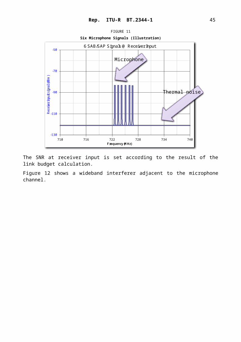
Rep. ITU-R BT.2344-1 47
TABLE 10
Definition of video SAB/SAP links (subset of Annex 1 of ERC/REC 25-10)
Type of link Definition
Wireless camera(line-of-sight)
Handheld or otherwise mounted camera with integrated or Clip-on transmitter, power pack and antenna for carrying broadcast-quality video together with sound signals over short-ranges line-of-sight
Wireless cameras(non-line-of-sight)
Handheld or otherwise mounted camera with integrated or Clip-on transmitter, power pack and antenna for carrying broadcast-quality video together with sound signals over short-ranges non-line–of-sight
Miniature camera/links
Very small transmitter and miniature camera for specialist action shots, e.g. helmet cam, covert assignments, UAV, etc. Can be body worn or covert assignments.
Portable video link Small transmitter, for deployment over greater ranges, typically up to 2 km
Mobile air-to-ground video link
Video transmission system employing radio transmitter and receivers mounted on helicopters, airships or other aircraft.(includes repeaters and relays)
Mobile vehicular video link (including ground-to-air)
Video transmission system employing radio transmitter mounted in/on motorcycles, racing motorbikes, pedal cycles, cars, racing cars or boats. One or both link terminals may be used while moving.
Temporary point-to-point video links
Temporary link between two points (e.g. part of a link between an OB site and a studio or network terminating point), used for carrying broadcast quality video/audio signals. Link terminals are mounted on tripods, temporary platforms, purpose built vehicles or hydraulic hoists. Two-way links are often required.
Any and all of the SAB/SAP elements described above plus audio SAB/SAP and service links may be present in a production as illustrated in Fig. 20.

48 Rep. ITU-R BT.2344-1
FIGURE 20Actual Example of ENG/OB demand for audio and service link channels in a European event

Rep. ITU-R BT.2344-1 49
FIGURE 21Wireless camera
As shown in Fig. 21, conventional wireless camera transmitter docks on the back of a traditional camera. Audio is incorporated with the pictures on the wireless camera link either from an on-board microphone or else there may be a separate radio microphone receiver mounted on the camera. Remote control of the camera for colour balance, iris and tally light can also be by radio telemetry via a separate wireless channel received on the camera.
FIGURE 22Cordless on board camera
Often to bring pictures from close to the action, miniaturized cameras and transmitters are mounted on participants in cycling and motorsport (see Fig. 22), utilizing low profile antennas, such as patch antennas, to minimize the impact on performance. These can then be received on the ground via a network of switched receivers placed along the route, or received via an airborne platform.

50 Rep. ITU-R BT.2344-1
To give a reliable link over a greater range a Portable Camera Transmitter is used along with a directional antenna. In the example in Fig. 23 below, being moved to a new location, the transmitter, its only portable power supply, test equipment and the directional antenna are carried on a trolley. Once in place the camera is connected to it by cable. Typical applications would be motorsport or a golf course where the camera location is determined by the action. The equipment may also be mounted on a vehicle such as a golf buggy.
FIGURE 23Portable camera transmitter
Mobile links can be mounted on a variety of vehicles including cars, buggies and motorcycles. In the example depicted in Fig. 24 below the cameraman sits on the rear of the motorcycle connected by cable to the video link, its components in the rear panniers and above the rear wheel. A low gain, typically a patch antenna, is mounted high, for safety and a clear view of the sky. RF power is limited by the EMF human exposure limits.

Rep. ITU-R BT.2344-1 51
FIGURE 24Mobile vehicular video link
FIGURE 25Airborne video link
52 Rep. ITU-R BT.2344-1
On the above Fig. 25, the gyroscopically stabilized camera can be seen on the front of the helicopter with receive and transmit antennas mounted on the landing skids. Other airborne vehicles such as airships and tethered blimps can also carry airborne video links.
As well as relaying pictures directly from the on-board camera the airborne platform can additionally receive multiple links from the ground, then transpose and transmit them down to another point on the ground. In Fig. 26 below is an example of the on-board equipment required, perhaps for coverage of a marathon or cycle race.
FIGURE 26Airborne video link equipment

Rep. ITU-R BT.2344-1 53
FIGURE 27Temporary point-to-point video links
In the left picture there are two auto tracking units installed in a hydraulic lift. These units will track by means of GPS information from the helicopter- or aircraft downlinks.
Point-to-point video links are used to relay pictures, sound and data from remote locations to a central production location. Programme makers need their own high quality, low delay links to be able to seamlessly combine the elements of a production. These may be relatively short distances for an individual camera at a horse racing meeting or many kilometres from a remote outside broadcast part way along a cycle race, to the finish line.
3.1 Applications versus spectrum limitations
3.1.1 Airborne use
Whilst the majority of airborne use is from helicopter’s there are also a range of other airborne use from airships to parachuting and the recent sub space height record.
Please note: Relay plane use high altitude (20.000 ft., ca. 6 100 m) often giving the need for harmonization for SAB/SAP frequencies and a quick coordination scheme between Administrations
All of these applications have one thing in common: a requirement for the transmitter and receiver antenna to “see” each other whilst the subject is moving.
Whilst auto tracking systems are a vital part of the link budget the physical factors and beam width determine the success of such a system.
Currently the 2-3 GHz band proved the best and in some cases the only spectrum available for airborne use.
3.1.2 Car and motorcycle use
This varies from rally cars to hill climbs and track racing, in each application the speed and terrain stretch the limits of the link budget with added complications of propagation in forests and pit arrears. Antenna size and coverage on both the transmitter and receiver have physical and technical limitations.
Once again the best and in many cases the only practical combinations can be achieved in the 2-3 GHz band

54 Rep. ITU-R BT.2344-1
3.1.3 Cycle racing both road and track
Wireless cameras have a number of formats when covering these applications, the prime one being the helmet camera of the cyclist which is physically small and limited in its antenna size and its output power (by both power source and EMF limits).
In addition vehicle, motor bike and airborne use will be used to cover an event.
Once again the best and in many cases the only practical combinations due to the obstructed propagation path can be achieved in the 2-3 GHz band
In many cases a low power head camera will be relayed to an aircraft or helicopter via a motorcycle, once again the EMF safety issue need careful consideration for the motorcycle personal.
3.2 Other applications
A range of activities such as yachting and powerboat racing will suffer from similar issues to those above plus the propagation losses from operating over water. In many cases a relay helicopter will be used to provide the link back to the Outside Broadcasting venue
FIGURE 28Relay helicopter
Golf in particular suffers from obstructed line of sight propagation even when using golf buggies as repeaters.
3.3 Current usage of certain frequency bands for wireless camera and video links in CEPT countries
During the development of this Report [2], the ECC developed a questionnaire to CEPT administrations on the regulatory procedures used by administrations in granting access to spectrum for SAB/SAP. It covers many frequency ranges and SAB/SAP usages.
Band 2 025-2 110 MHz (ERC/REC 25-10 [15]): From the 32 countries providing a response on this band, 19 of them report about the availability of the band or parts of it for SAB/SAP applications, namely temporary video links (portable, mobile with some allowance for airborne use)

Rep. ITU-R BT.2344-1 55
and wireless cameras as referred to in ERC/REC 25-10. This use is under an individual licensing regime. No change is expected for this band in relation to SAB/SAP.
Band 2 200-2 500 MHz (ERC/REC 25-10): From the 32 countries providing a response on this band, 29 of them report about the availability of the band or parts of it for SAB/SAP applications.
The main type (28 countries) is related to temporary video links (portable, mobile with some allowance for airborne use) and wireless cameras as referred to in ERC/REC 25-10. In most cases, this use is under an individual licensing regime, although low power wireless cameras can in a few countries operate under a general license. It is noted that, in addition or as an alternative, two countries mention specifically the use of the 2 400-2 483.5 MHz band for wideband data transmissions or non-specific SRD as per REC 70-03 for SAB/SAP purpose. Five countries mentioned that current considerations on the potential introduction of Broadband Wireless systems either as a single block or via Llicensed Shared Access (LSA)4 in the band 2 300-2 400 MHz will have an impact on the availability of the band for SAB/SAP.
Band 2 500-2 690 MHz (ERC/REC 25-10): From the 32 countries providing a response on this band, 5 of them report about the availability of the band or parts of it for SAB/SAP application, namely SAB/SAP, video links. Amongst those, 3 countries expect that the use of SAB/SAP will cease because of the introduction of terrestrial Electronic Communications Networks in the 2 500-2 690 MHz band. On this basis, the relevance of maintaining this band in the ERC/REC 25-10 may be considered.
Band 3 400-3 600 MHz (ERC/REC 25-10): From the 32 countries providing a response on this band, 9 of them report about the availability of the band or parts of it for SAB/SAP applications, which tends to confirm a decrease of the availability of this band for SAB/SAP. SAB/SAP applications in this band cover temporary video links (portable, mobile with some allowance for airborne use) and wireless cameras as referred to in ERC/REC 25-10 [15]. This use is under an individual licensing regime. The development of IMT in this band may have an impact on the spectrum available for SAB/SAP in this band.
Band 4 400-5 000 MHz: From the 32 countries providing a response on this band, 7 of them report about the availability of the band or parts of it for SAB/SAP applications. SAB/SAP applications in this band cover SAB/SAP links for temporary use deployed in a coordinated way to protect other use (mainly military applications). This SAB/SAP use is in most cases under an individual licensing regime.
Band 10.0-10.68 GHz (ERC/REC 25-10): From the 32 countries providing a response on this band, 26 of them report about the availability of the band or parts of it for SAB/SAP applications. The amount of available spectrum and the frequency bands within the overall tuning range vary significantly depending upon the country. The main SAB/SAP applications covered in this range are wireless cameras, portable video links and point-to-point video links for temporary use as referred to in ERC/REC 25-10. This use is in most cases under an individual licensing regime. No major change is generally expected for this band in relation to SAB/SAP.
Band 21.20-24.50 GHz (ERC/REC 25-10): From the 32 countries providing a response on this band, 25 of them report about the availability of the band or parts of it for SAB/SAP applications. The amount of available spectrum and the frequency bands within the overall tuning range vary significantly depending upon the country. The main SAB/SAP applications covered in this range are wireless cameras, portable video links and point-to-point video links for temporary use as
4 An LSA system comprises one or more incumbents, one or more LSA licensees, and the means to enable coordination between incumbents and LSA licensees, such that the latter may deploy their networks without harmful interference.
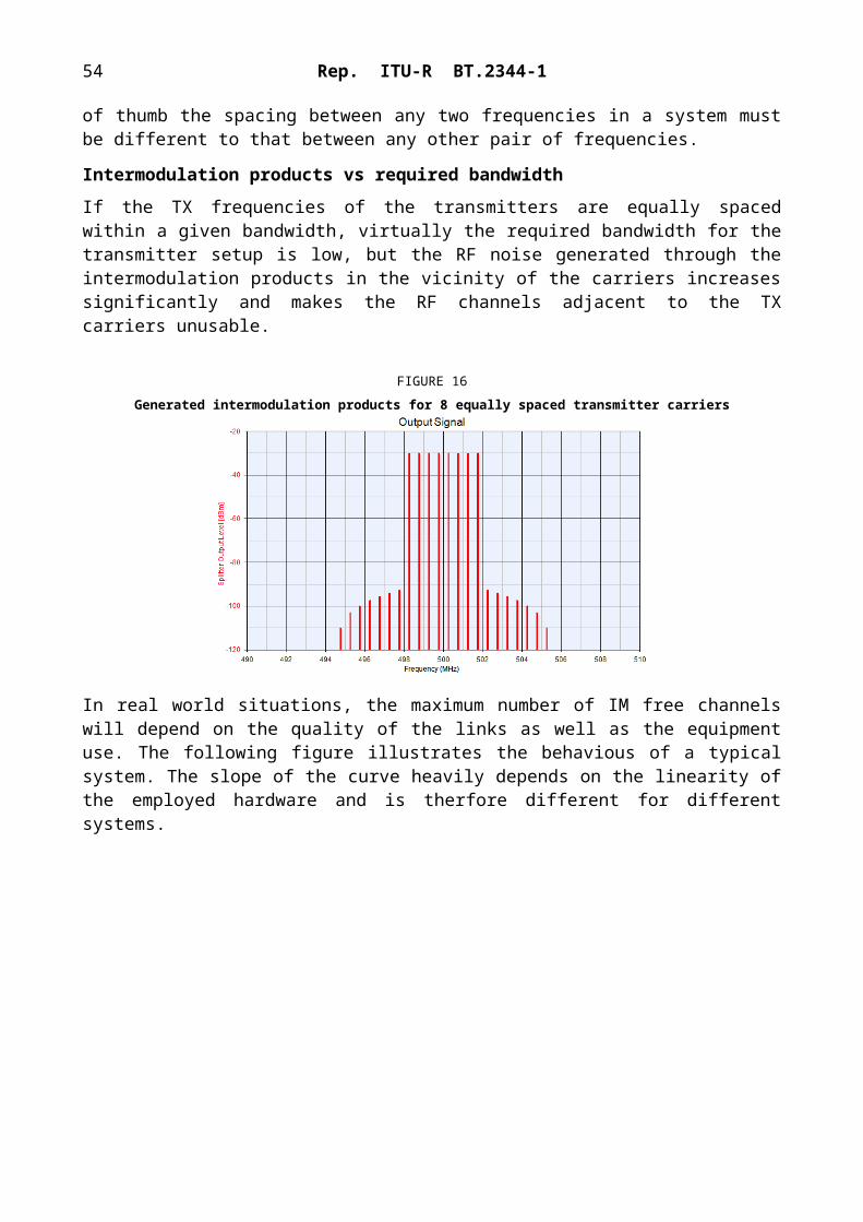
56 Rep. ITU-R BT.2344-1
referred to in ERC/REC 25-10. This use is in most cases under an individual licensing regime. A few changes are expected, which may slightly increase the availability of spectrum for SAB/SAP.
Band 47.20-50.20 GHz (ERC/REC 25-10): From the 32 countries providing a response on this band, 16 of them report about the availability of the band or parts of it for SAB/SAP applications. The main SAB/SAP applications covered in this range are wireless cameras and portable video links as referred to in ERC/REC 25-10. This use is in most cases under an individual licensing regime. No change is expected with regard to SAB/SAP in this band.
Other bands: The availability of frequency bands within the 6/8 GHz range is mentioned by eight countries for fixed and/or mobile ENG/OB.
3.4 HDTV digital terrestrial electronic news gathering (ENG) in Japan
Since HDTV digital satellite-broadcasting service was launched in 2000 in Japan, HDTV digital terrestrial ENG systems have been introduced, as well as HDTV digital SNG systems. In Japan, the 5 GHz band (18 MHz bandwidth 2 ch), the 6 GHz band (18 MHz bandwidth 6 ch), the 7 GHz band (18 MHz bandwidth 9 ch), the 10 GHz band (18 MHz bandwidth 18 ch) and the 13 GHz band (18 MHz bandwidth 16 ch) were assigned to the mobile analogue and HDTV digital microwave links. The band 770-806 MHz (9 MHz bandwidth 4 ch) was also assigned to the mobile analogue SDTV and digital HDTV links, and partially to radio microphones as well.
In 2011 the band 710-806 MHz was reassigned to commercial mobile phone and other applications. In consequence the 1.2 GHz band and 2.3 GHz band were newly assigned to the incumbent ENG systems. This frequency reassignment should be completed by March 2019. In Tables 11 and 12, examples of user requirements and technical parameters for the transmission of digital TV signals over portable microwave links are shown. In order to meet the requirements, transmission systems were developed. For fixed operation and transmission from helicopters, single carrier QAM systems (ARIB STD-B11 [16]) are used. For mobile transmission and wireless camera systems, OFDM systems (ARIB STD-B33 [17]) are used. Each system has a postcard-sized HDTV compression encoder or decoder in it. System parameters for the HDTV/SDTV digital microwave links are shown in Table 13. Moreover, the 42 GHz band (80 MHz bandwidth 5 ch) and the 60 GHz band (1 GHz bandwidth 1 ch) are also allocated to the mobile TV links and future low-delay HDTV digital microwave links. The frequency bands for the broadcasting programme relay service are assigned exclusively except for some bands which are shared with fixed-satellite services, and only the interference with the same service is mainly considered.
ARIB: Association of Radio Industries and Businesses of Japan.

Rep. ITU-R BT.2344-1 57
TABLE 11
Example of user requirements and technical parameters for transmission of digitalHD/SDTV signals over fixed/airborne (line-of-sight) portable microwave links
User requirements Technical parameters
Received picture quality
HDTV:As specified in Recommendation ITU-R BT.1121 for 3-codecs in tandem
SDTV:As specified in Recommendation ITU-R BT.1205 for single codec
HDTV:Video bit rate: 52 Mbit/s(Using ISO/IEC 13818-2(ITU-T Rec. H.262) 422P@HL with long-GOP)Video bit rate: 35 Mbit/s(Using ISO/IEC 14496-10(ITU-T Rec. H.264) Level 4/High 4:2:2, 1920, CAVLC)(1)
SDTV:Video bit rate: 15 Mbit/s × 3 ch(Using ISO/IEC 13818-2(ITU-T Rec. H.262) MP@ML with long-GOP)
Received sound qualityComparable to uncompressed
LPCM(48 kHz, 16 bit/ch)
Total audio bit rate: 2 Mbit/sUncompressed 768 kbit/s per
channel × 2 chMPEG-1 layer II 250 kbit/s per
channel × 8 chNumber of sound channels 2 to 8
Latency As short delay as possible < 500 msTransmission bandwidth 18 MHz Nyquist bandwidth: 13.5 MHz
Roll off: 30%Transmission bit rate: 81 Mbit/sInformation bit rate: 60 Mbit/sModulation: 64-QAM
Transmission power 1.5 W
Frequency6-7 GHz, 10 GHz, and
13 GHz bands
Fixed Tx antenna 0.6 m dishTransmission distance:6-7 GHz: 50-100 km
(depending on necessary margin)10 GHz: 7 km
(with necessary rain margin)13 GHz: 5 km
(with necessary rain margin)
Rx antenna 0.6 m dish
Airborne Tx antenna 0.2 m dishTransmission distance:6-7 GHz: 50-65 km
(depending on necessary margin)10 GHz: 7 km
(with necessary rain margin)13 GHz: 5 km
(with necessary rain margin)
Rx antenna 1.2 m dish

58 Rep. ITU-R BT.2344-1
TABLE 12
Example of user requirements and technical parameters for transmission of digitalHD/SDTV signals over mobile (non line-of-sight) portable microwave links
User requirements Technical parameters
Received picture quality As specified in Recommendation ITU-R BT.1205 for single codec
HDTV:Video bit rate: 27 Mbit/s(Using ISO/IEC 13818-2(ITU-T Rec. H.262) MP@HL with long-GOP)Video bit rate: 21 Mbit/s(Using ISO/IEC 14496-10(ITU-T Rec. H.264) Level 4/High, 1920, CAVLC)(1)
Video bit rate: –14 Mbit/s(Using ISO/IEC 14496-10(ITU-T Rec. H.264) Level 4/High, 1440, CABAC)(1)
SDTV:Video bit rate: 15 Mbit/s(Using ISO/IEC 13818-2(ITU-T Rec. H.262) MP@ML with long-GOP)
Received sound qualityComparable to uncompressed
LPCM(48 kHz, 16 bit/ch)
HDTV:Total audio bit rate: 2 Mbit/sUncompressed 768 kbit/s perchannel × 2 chMPEG-1 layer II 250 kbit/s perchannel × 8 ch
SDTV:MPEG-1 layer II 250 kbit/s perchannel × 4 ch
Number of sound channels HDTV: 2 to 8SDTV: 1 to 4
Latency As short delay as possible < 500 ms
Transmission bandwidth HDTV: 18 MHzSDTV: 9 MHz
HDTV:Information bit rate: 32 Mbit/sModulation: 16-QAM/QPSK-OFDM
SDTV:Information bit rate: 16 Mbit/sModulation: 16-QAM/QPSK-OFDM
UHF
Transmission power
HDTV: 5 WSDTV: 5 W
Transmission distance: 4 kmFrequency 800 MHz bandTx antenna Co-linearRx antenna Yagi

Rep. ITU-R BT.2344-1 59
TABLE 12 (end)
User requirements Technical parameters
UHF
Transmission power
HDTV: 25 WSDTV: 12.5 W
Transmission distance: 1-10 kmFrequency 1.2 GHz bandTx antenna Co-linearRx antenna Yagi
UHF
Transmission power
HDTV: 40 WSDTV: 20 W
Transmission distance: 1-10 kmFrequency 2.3 GHz bandTx antenna Co-linearRx antenna Yagi
Microwave
Transmission power
HDTV: 5 WSDTV: 2.5 W
Transmission distance: 4 kmFrequency 6-7 GHz, 10 GHz and 13 GHz bands
Tx antenna HornRx antenna 0.3 m dish

60 Rep. ITU-R BT.2344-1
TABLE 13
Parameters of BAS video link systems operated in the mobile service
Frequency allocation 770-806 MHz 1 240-1 300 MHz2 330-2 370 MHz
5 825-5 900 MHz6 425-6 570 MHz6 870-7 125 MHz
10.25-10.45 GHz10.55-10.68 GHz12.95-13.25 GHz
Note
Antenna type and gain
Helix (10-13 dBi) Helix (10-13 dBi) Parabolic (22-35 dBi)Helix (10-13 dBi) H, V or circular polarization
YAGI (12-19 dBi) YAGI (12-19 dBi) Horn (5-20 dBi) Circular polarizationCo-linear (5-6 dBi)
Non-directional (2 dBi)
Co-linear (5-6 dBi)Non-directional
(2 dBi)
Horn (15-20 dBi)Non-directionnel (2 dBi) H and V polarization
Tracking method Automatic or Manual
ModulationQPSK-OFDM
16-QAM-OFDM32-QAM-OFDM
BPSK-OFDMQPSK-OFDM8PSK-OFDM
16-QAM-OFDM32-QAM-OFDM64-QAM-OFDM
QPSK-OFDM16-QAM-OFDM32-QAM-OFDM64-QAM-OFDM
16-QAM-OFDM is normally adopted
Maximum capacity (Mbits/s) 16 30 60 30 60 30 60Channel spacing (MHz) 9 9 18 9 18 9 18Feeder/multiplexer loss(typical) (dB) 1 1 1 1 1 1 For both transmitter and receiver
Maximum antenna input power (dB) 7 11***
13****14***
16**** 4 7 4* 7**
* –6 dBW in 10.60-10.68 GHzby the transmitter power.
** –3 dBW in 10.60-10.68 GHzby the transmitter power.
*** 1 240-1 300 MHz**** 2 330-2 370 MHz
e.i.r.p. (Maximum) (dBW) 25 29***31****
32***34**** 38 41 38* 41**
* 29 dBW in 10.60-10.68 GHz.** 32 dBW in 10.60-10.68 GHz. *** 1 240-1 300 MHz**** 2 330-2 370 MHz

Rep. ITU-R BT.2344-1 61
TABLE 13 (end)
Frequency allocation 770-806 MHz 1 240-1 300 MHz2 330-2 370 MHz
5 825-5 900 MHz6 425-6 570 MHz6 870-7 125 MHz
10.25-10.45 GHz10.55-10.68 GHz12.95-13.25 GHz
Note
Receiver IF Bandwidth (MHz) 9 9 18 9 18 9 18
Receiver noise figure (dB) 4 4 4 4 4 4 4
Receiver thermal noise (dBW) –130.5 –130.5 –127.4 –130.5 –127.4 –130.5 –127.4
Normal Rx input level (dBW) –88SISO MIMO
–88 –85 –88 –85* 64-QAM(3/4)** 16-QAM-MIMO*** 16-QAM(2/3)–93* –103** –97*** –100**
Rx input level for 1 × 10⁻³ BER (dBW)
––120
––113
–110.7–
–122.8*–119.6*–115.0*–113.0*–110.0*–107.2*
–123.0*–121.5*–115.5*–111.5*
––
–119.7*–116.5*–111.9*–109.9*–106.9*–104.1*
–119.9*–118.4*–112.4*–108.4*
––
––120
-–113
–110.7–108.2
––116.9
-–109.9–107.6–105.1
––120
-–113
–110.7–108.2
––116.9
-–109.9–107.6–105.1
BPSK-OFDMQPSK-OFDM8PSK-OFDM16-QAM-OFDM32-QAM-OFDM64-QAM-OFDM*Rx input level for 1 × 10⁻⁴
BERNominal long term interference (dBW) –140.5 –140.5 –137.4 –140.5 –137.4 –140.5 –137.4
Spectral density (dB(W/MHz)) –150.0 –150.0 –150.0 –150.0 –150.0 –150.0 –150.0
NOTE – Table 13 incorporates references from Table 1 of Annex 1 to Recommendation ITU-R M.1824.

62 Rep. ITU-R BT.2344-1
3.5 Technical characteristics and deployment scenarios of wireless camerasand video links
3.5.1 Live news gathering
It is commonplace to pair a wireless camera with a vehicle equipped with a satellite uplink or alternatively a terrestrial video link. There is the safety benefit and flexibility of not having to run cables between the camera and the vehicle as well as permitting optimum placement of the camera and vehicle link terminal.
FIGURE 29Wireless camera for news gathering
3.5.2 Sports coverage
The rugged nature and reliability of digital wireless camera links has led to much greater use in coverage of sporting events. Wireless cameras are routinely deployed close to the action and can be handheld or mounted on moving vehicles.

Rep. ITU-R BT.2344-1 63
FIGURE 30Wireless camera for Sports Coverage
3.5.3 Major events
Live coverage of major state occasions and major cultural events are greatly enhanced through the use of Wireless camera and Video Links. Audiences have come to expect the wide range of shots from different standpoints along with close-ups that show the detail of the action. These are only possible when cameras can be located in a variety of locations, without the need to be cabled.

64 Rep. ITU-R BT.2344-1
FIGURE 31Wireless camera for major event coverage where cabling is not an option
Portable Video links are employed where path lengths are greater, for example to provide reliable and rugged coverage over wide areas, perhaps an entire golf course. Lower power Wireless cameras with shorter paths to a greater number of receive points are an alternative but practical and cost implications will determine the operational decisions. Multiple hops can permit a lower power Wireless camera to be relayed on via a higher power video link perhaps rigged in a vehicle such as a motorbike or golf buggy.
The use of video links has grown exponentially as the artistic freedom they create has resonated with producers and directors in all forms of media. Their deployment spans all forms of programme making with variations in each sector for example the film industry uses “video assist” 5 to allow the director to see the set from the remote cameras and the attachment of wireless cameras to formula 1 and rally cars or even whales and insects. Figures below provide an indication of their popularity.
5 Please see Annex 3 (service link annex) for further information.

Rep. ITU-R BT.2344-1 65
3.5.4 Considerations on SAB/SAP deployment scenarios and planning practice
The temporary nature of SAB/SAP deployment can lead to less than optimum installation practices. Production vehicles and equipment are often corralled closely together creating radio frequency hotspots. Isolation between radio systems may therefore have to be compromised and it is not always possible to efficiently use spectrum in the way it would be possible with a permanent installation. The need to co-ordinate multiple SAB/SAP users occupying the same ranges of spectrum can also limit the possibilities to promote the optimum use of spectrum in an operational environment where requirements are continually changing.
FIGURE 32A temporary and less than optimum installation for Major Event coverage

66 Rep. ITU-R BT.2344-1
TABLE 14
Typical technical characteristics for ENG/OB video links
Type of link Range Typical Tx power
Tx antenna gain @ height agl6
Rx antenna gain @ height agl7 Frequency range (GHz)
Wireless camera line-of-sight <500 m 20 dBm 0-3 dBi @1-2 m 3-13 dBi @2-60 m 2 to 8
Wireless camera non-line-of-sight <500 m 20 dBm 0-3 dBi @1-2 m 3-13 dBi @2-60 m 2 to 3.5
Miniature link <200 m 20 dBm 0-3dBi @ 100 m 3-13 dBi @ 2-60 m 2 to 3.5
Portable link <2 km 33 dBm 6-14 dBi @ 1-4 m 9-17 dBi @ 2-60 m 2 to 8 depending on path
Air to ground link <100 km
36 dBm 3-9 dBi @ 15 m-6 km
17-24 dBi (2 GHz) @ 2-60 m34 dBi (7 GHz) @ 2-60 m
<8
Mobile vehicular link (including ground-to-air)
<10 km 30 dBm 3-9 dBi @1-4 m 10-13 dBi @ 2-60 m4-9 dBi @150 m-6 km (airborne)
2 to 3.5
Temporary point-to-point link <80 km per hop
33 dBm 24-38 dBi (7 GHz)@ 20-60 m
24-38 dBi (7 GHz)@ 20-300 m
<5-10 for long hops.Hop length at >10 limited by precipitation fading
6 Typical and maximum value7 Typical and maximum value

Rep. ITU-R BT.2344-1 67
3.5.5 Technical characteristics
Multicarrier forms of digital modulation have become the preferred option with their rugged and reliable performance in the presence of multipath propagation over varying and often obstructed paths. DVB-T based links are popular and further proprietary systems have subsequently been introduced to accommodate the need for greater data capacity for High Definition and 3D. Used alongside cabled cameras and other high quality sources it is imperative for Wireless cameras and Portable Video Links to match the same high quality and not appear inferior to the production process and the viewer.
3.5.6 Technological developments
The market for SAB/SAP equipment is small compared to other radio sectors but new technologies are being developed in parallel with the broadcast, security surveillance and military sectors.
Mesh technologies improve the reliability of links but there is a trade off in complexity of cost of the systems and their deployment as well as the additional need to ensure low delay in SAB/SAP compared to other applications.
Airborne links have employed military technologies permitting dynamically steerable antennas at high altitude compared to the traditional less directional airborne antennas used at lower altitudes from helicopters.
4 Band by band assessment on the sustainable operation of wireless cameras and video links
Deployment of video links as with other radio services is dependent upon a range of factors which contribute to the link budget8, a major consideration is the propagation of the spectrum , to date the 2 GHz band provides the best conditions for many application’s especially for airborne and mobile use. The relative bandwidth and size of 2 GHz antenna allow automatic or manual antenna systems to track successfully for mobile use, the higher the frequency the narrower the bandwidth of the antenna and therefore harder to successfully track when mobile
4.1 Band 1- 5 GHz
Frequency ranges below 5 GHz are favoured for low power wireless cameras operating over short obstructed paths, with the advantage of relatively low diffraction loss. Multiple carrier forms of digital modulation, particularly COFDM, which are rugged and perform well in the presence of multipath, have driven greater and increasing use of low power wireless cameras in recent years.
4.2 Band 5-12 GHz
The frequency range between 5 GHz and 12 GHz is favoured for:• High power airborne down-links working line of sight: In these frequency bands stable
pictures from moving aerial objects can only be obtained by auto tracking systems. Using DVB-S2 for downlinking no diversity or MIMO techniques are available;
• Low power wireless cameras in use should be DVB-T or ISDB-T based to benefit from reflections and diversity techniques;
• Medium power short and middle range point to point links: Equipment in use will carry encoded video signals via DVB-T, DVB-S2 (for multiple video, audio signals) or IP links (for bidirectional multiple video, audio and data signals).
8 Please see ERC Report 38 Error: Reference source not found[18] for further details.

68 Rep. ITU-R BT.2344-1
4.3 Band 12 GHz and above
Frequency ranges above 12 GHz are favoured for low power short range point to point links.
Equipment in use will carry encoded video signals via DVB-T, DVB-S2 (for multiple video, audio signals) or IP links (for bidirectional multiple video, audio and data signals).
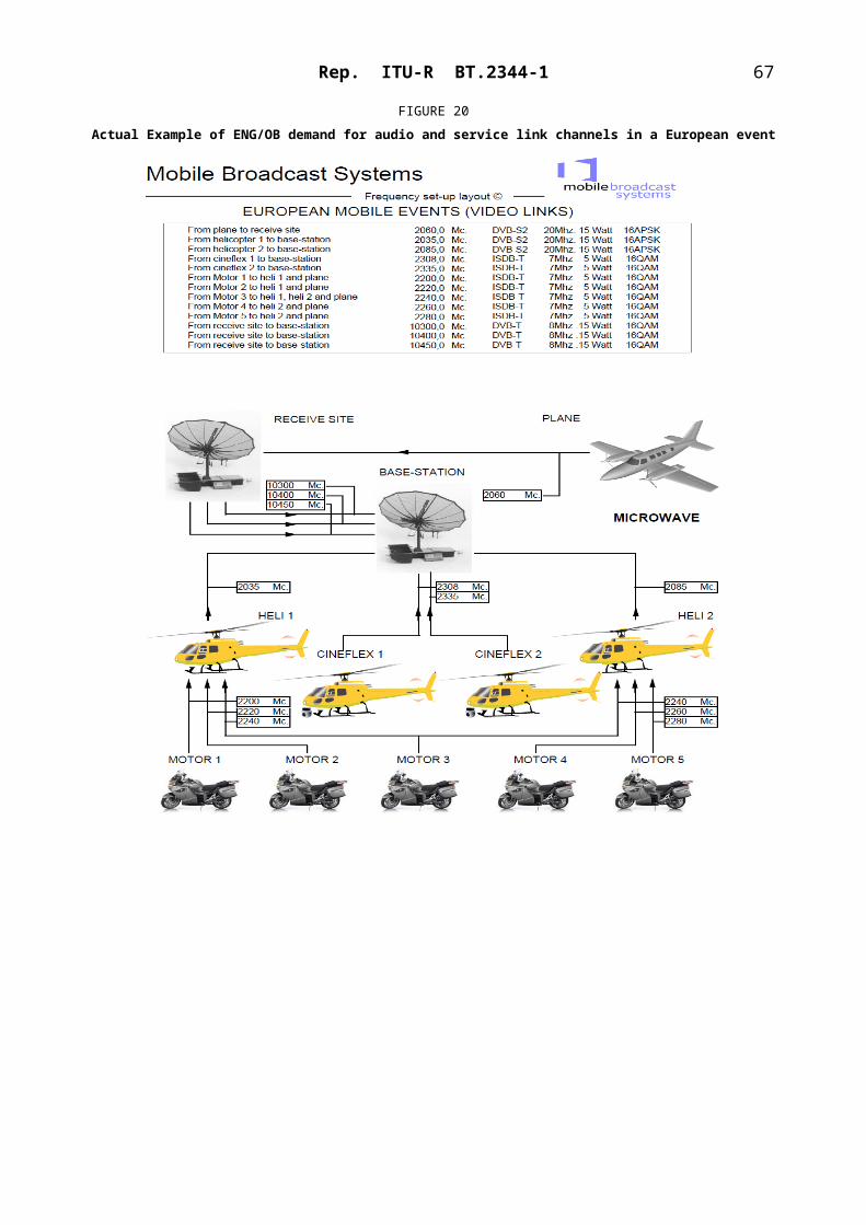
Rep. ITU-R BT.2344-1 69
Annex 4
Development of SAB/SAP for UHDTV in Japan
1 Introduction
Ultra-high definition television (UHDTV) is certain to be one of the major applications of next-generation digital terrestrial broadcasting. Recommendation ITU-R BT.2020 – Parameter values for ultra-high definition television systems for production and international programme exchange, was published for this purpose in 2012.
Since 2012, studies on the transmission of UHDTV on DTT networks were started in several countries, and the results summarised in Report ITU-R BT.2343. Additionally, WP 4B developed draft new Recommendation ITU-R BO in June 2015.
With ever more programs being produced for UHDTV, SAB/SAP for UHDTV has become an urgent requirement.
This Annex addresses the latest developments in SAB/SAP for UHDTV.
2 Example developments
2.1 Temporary video link for 8K
The transmission of uncompressed video and audio signals (baseband signals) from a camera is an essential requirement of live production in the field, and UHDTV will be no exception. Taking the high bit rate of uncompressed UHDTV signals into account, a huge amount of additional capacity will be needed. The frequency bands now being used for temporary HDTV video links are used heavily by existing services and have no potential for future expansion.
A UHDTV temporary video link using the 120 GHz band has therefore been developed in Japan to make use of the wider bandwidth and higher capacity of the millimetre band. This 120 GHz video link will carry uncompressed Dual Green 8K signals (formatted with the Bayer colour filter array, which has very similar quality to full 8K) with a data rate of 24 Gbit/s.
2.1.1 Example uses
Temporary video links can be used when it is difficult or unfeasible to use a cable, such as in a stadium, on a golf course, or in the case of some huge obstacle.
Figure 33 shows an example of usage in a stadium, where the transmission distance is estimated at 250 m.
Figure 34 shows an example of usage on a golf course, where the transmission distance is estimated at 1 km.
Figure 35 shows an example of usage in case of transmitting over obstacles (ex. road, river) where the transmission distance is estimated at 4 km.

70 Rep. ITU-R BT.2344-1
FIGURE 33Stadium
FIGURE 34Golf Course
FIGURE 35Transmission over obstacles
2.1.2 Technical specifications
As shown in Fig. 36, 16 HD-SDI signals consisting of the Dual Green 8K signal are multiplexed into 2 groups. Each group containing 8 HD-SDI signals is transmitted by either vertical or horizontal polarization of the 120 GHz band video links.
Transmitting point
Receiving point
Transmitting point
Receiving point
Obstacles (road)
Transmitting point
Receiving point

Rep. ITU-R BT.2344-1 71
The major advantage of the 120 GHz band video link is its high transmission capacity. The uncompressed 8K signal is all contained in the 17 GHz bandwidth. The use of uncompressed transmission maintains the full video and audio quality of 8K, as well as minimizing the transmission latency.
FIGURE 36Overview of the temporary 120 GHz band video link for 8K
Reed-Solomon Code (986, 966) for error correction is implemented when the baseband processer multiplexes the 8 HD-SDI signals into a single serial data stream (at the receiving end, this serial data stream is de-multiplexed into the original 8 HD-SDI signals and errors which arose during propagation are corrected up to BER = 1* 10–4). This improves the required C/N by approximately 4 dB compared with when no error correction is implemented.
The technical parameters of the temporary video link are shown in Table 15.
TABLE 15
Technical parameters of the 120 GHz band temporary video link [19]
Centre frequency (GHz) 125Bandwidth (GHz) 18 (116 – 134)Polarization Horizontal, vertical, circularMaximum Tx power (W) 1.0Modulation ASK BPSK QPSKMaximum bit rate (Gbit/s) 12.0 12.0 24.0Required Rx input level (dBm) –30.4 –36.4 –31.5Required C/N* (dB) 25.0 19.0 23.9
* In case without error correction.

72 Rep. ITU-R BT.2344-1
2.1.3 Example link models
Table 16 shows examples of link models in three different situations. Please note that “Required margin” is set to 6 dB as a target for these situations.
TABLE 16
Examples of link models
Situation Stadium Golf course Transmission over obstacles
Weather* SunnyRequired transmission distance (km) 0.25 1.0 4.0Possible transmission distance (km) 0.29 1.1 4.4Modulation type ASKAntenna size (m) 0.20 0.14 0.48Antenna gain (dBi) 43.0 40.0 51.0Transmission power (mW) 10.0 1 000.0Transmission power (dBm) 10.0 30.0Feeder loss (dB) 1.0e.i.r.p. (dBm) 52.0 69.0 80.0Attenuation by atmospheric gases (dB)3.0 dB/km
0.9 3.3 13.2
Free space propagation loss (dB) 123.5 135.1 147.2Reception power (dBm) –30.4Receiver noise figure (dB) 10.0
Boltzmann constant (dBm/(Hz・K)) –198.6
Standard temperature (dBK) 24.8Bandwidth (dBHz) 102.4Noise power (dBm) –61.4Receive C/N (dB) 31.0Required margin (dB) 6
* In case of rain (assuming 60 mm/h intensity) 23dB/km attenuation needs to be considered.
2.1.4 Trial 8K public viewing
8K public viewing of the 66th Sapporo Snow Festival was staged in February 2015. The site survey revealed that no optical cable was available between the festival site and public viewing venue, and the use of a temporary cable was unfeasible due to heavy traffic on roads around the site.
The use of a temporary 120 GHz band video link was therefore selected for this public viewing and the system was configured in the same manner as for the live broadcast. The system diagram is shown in Fig. 37.

Rep. ITU-R BT.2344-1 73
FIGURE 37System diagram for 8K public viewing
The 8K UHDTV signals were multiplexed in the production booth near the festival site, and sent to the transmitters using optical fiber. The temporary 120 GHz band video link then transmitted the signals to the other side of the road across a distance of approximately 160 m. Once received at the television tower, the signals were then sent on to the public viewing venue over an existing optical fiber link (see Fig. 38).
FIGURE 38Transmitter and receiver
Rainy weather was experienced during this 120 GHz band video link trial. Millimeter waves are very susceptible to influence from rainfall due to their short wave length and attenuation of approximately 4 dB was recorded for both polarizations. This trial, however, was designed with a 17 dB C/N margin and this was sufficient to transmit the 8K signals without uncorrectable errors. In addition, heavy snowfall was experienced during the event, but with no evident impact on the reception power. This trial confirmed that the 120 GHz band video link for 8K UHDTV does have the potential for use even in difficult weather conditions.

74 Rep. ITU-R BT.2344-1
FIGURE 39Public viewing venue
3 Summary
This annex introduced the temporary 120 GHz band video link and example development of SAB/SAP for UHDTV in Japan. Considering that studies on UHDTV transmission on DTT network have already been started in several counties, much is expected of future development of SAB/SAP for UHDTV from both the technical and the operational points of view.
Rep. ITU-R BT.2344-1 75
Annex 5
References
[1] ECC Report 002: SAP/SAB (Incl. ENG/OB) spectrum use and future requirements.[2] Resolution 232 (WRC-12) – Use of the frequency band 694-790 MHz by the mobile,
except aeronautical mobile, service in Region 1 and related studies.[3] Presentations from C-PMSE workshop, 29 May 2013,
http://cpmse.research-project.de/index.php/en/project/82-cpmsenewsen/119-demonstration-workshop
[4] Report ITU-R BS.2161 – Low delay audio coding for broadcasting applications.[5] EBU Technical Report 001, Results of the EBU questionnaire on spectrum requirements
for SAB/SAP & ENG/OB applications, http://tech.ebu.ch/docs/techreports/tr001.pdf [6] Questionnaire to CEPT administrations on the regulatory procedures used by
administrations in granting access to spectrum for PMSE (summary, full set of responses)[7] ERC Recommendation 70-03 – Relating to the use of Short Range Devices (SRD).[8] ARIB Standard STD-15 V 5.0 (2007-09) – Radio microphone for specified low power
radio station.[9] ARIB Standard RCR STD-22 V3.0 (2009-03) – Specified radio microphone for land
mobile radio station.[10] ARIB STD-T112 – Specified radio microphone for land mobile radio station.[11] ETSI EN 300 422 – Harmonized European Standard for radio microphones in the 25 MHz
to 3 GHz frequency range.[12] ETSI EN 301 357 – Electromagnetic compatibility and Radio spectrum Matters (ERM);
Cordless audio devices in the range 25 MHz to 2 000 MHz; Part 2: Harmonized EN covering essential requirements of article 3.2 of the R&TTE Directive.
[13] Report for OFCOM from Analysis Mason: spectrum Planning for the London 2012 Olympic and Paralympic Games Link Link Part 2
[14] FM48#7-Info11-Direct-Air-to-Ground Demo Flight Event in October 2012.[15] ERC Recommendation 25-10 – Frequency ranges for the use of temporary terrestrial audio
and video SAP/SAB links (incl. ENG/OB).[16] ARIB STD-B11 – Portable microwave digital transmission system for television program
contribution.[17] ARIB STD-B33 – Portable OFDM digital transmission system for television program
contribution.[18] ERC Report 38 – Handbook on radio equipment and systems video links for ENG/OB use.[19] ARIB STD-B65 – Portable 120 GHz BAND digital transmission system for ultra-high
definition television program contribution

76 Rep. ITU-R BT.2344-1
Other referencesEuropean competitiveness report 2010, http://bookshop.europa.eu/en/european-competitiveness-
report-2010-pbNBAK10001/Creative Industries Economic Estimates, December 2011, Department for culture, media and sport,
United Kingdom: https://www.gov.uk/government/uploads/system/uploads/attachment_data/file/77959/Creative-Industries-Economic-Estimates-Report-2011-update.pdf
Decision 243/2012/EU of 14 March 2012 “on establishing a multiannual radio spectrum policy program”.
Decision 2010/267/EU “on harmonized technical conditions of use in the 790-862 MHz frequency band for terrestrial systems capable of providing electronic communications services in the European Union”.
Decision 128/1999/EC “on the coordinated introduction of a third-generation mobile and wireless communications system (UMTS) in the Community”.
ECC Report 159: Technical and operational requirements for the possible operation of cognitive radio systems in the ‘white spaces’ of the frequency band 470-790 MHz.
ECC Report 185: Complementary Report to ECC Report 159. Further definition of technical and operational requirements for the operation of white space devices in the band 470-790 MHz.
ECC Report 186: Technical and operational requirements for the operation of white space devices under geo-location approach.
EC Mandate to CEPT on technical conditions regarding spectrum harmonization options for wireless radio microphones and cordless video-cameras (PMSE equipment).
CEPT Report 50: Technical conditions for the use of the bands 821-832 MHz and 1 785-1 805 MHz for wireless radio microphones in the EU.
CEPT Report 51: Technical conditions for ensuring the sustainable operation of cordless video-cameras in the EU.
ECC Report 191: Adjacent band compatibility between MFCN and PMSE audio applications in the 1 785-1 805 MHz frequency range.
ECC Report 121: Compatibility studies between Professional Wireless Microphone Systems (PWMS) and other services/systems in the bands 1 452-1 492 MHz, 1 492-1 530 MHz, 1 533-1 559 MHz also considering the services/systems in the adjacent bands (below 1 452 MHz and above 1 559 MHz).
ECC Report 44: Guidance for radio usage at special events.Ofcom and the London 2012 Olympic and Paralympic Games, http://stakeholders.ofcom.org.uk/
consultations/london2012/report-olympic-paralympic-2012/ CEPT Report 32: Recommendation on the best approach to ensure the continuation of existing
Program Making and Special Events (PMSE) services operating in the UHF (470-862 MHz).
The Wyndham report: the economic impact of London's West End theatre, 1998.UKEMTS 2011 Report on the development of the British event industry.Resolution 233 (WRC-12) – Studies on frequency-related matters on International Mobile
Telecommunications and other terrestrial mobile broadband applications.ERC Report 42: Handbook on radio equipment and systems radio microphones and simple wide
band audio links.

Rep. ITU-R BT.2344-1 77
European Commission Decision 2006/771/EC on harmonization of the radio spectrum for use by short-range devices.
ERC Report 25: The European table of frequency allocations and applications in the frequency range 9 kHz to 3 000 GHz.
Audio Engineering Society Standard 42.FM50(11)037 Appendix 2 from APWPT: Economic potential of PMSE applications.ARIB STD-B12 – Fixed microwave digital transmission system for television program
contribution.ARIB STD-B13 – 800MHz-BAND OFDM transmission system for television program
contribution.ARIB STD-B22 – Specified radio microphone for land mobile radio station.ARIB-STD-B43 – Portable MILLIMETER-WAVE digital transmission system for television
program contribution.ARIB STD-B57 – 1.2 GHz/2.3 GHz-BAND portable OFDM digital transmission system for
television program contribution. “Report of Mobile Communication Subcommittee, Information and Communications Council”
http://www.soumu.go.jp/main_content/000225030.pdf (in Japanese).Report ITU-R F.2107 – Characteristics and applications of fixed wireless systems operating in
frequency range between 57 GHz and 134 GHz.
______________