doc.id: abs-pdp-dpv1-1 rev. 1 -...
TRANSCRIPT

GermanyJapanSwedenU.S.A
[email protected]@[email protected]@hms-networks.com
"+ 49 - 721 - 96472 - 0+ 81 - 45 - 478 -5340+ 46 - 35 - 17 29 20+ 1 - 773 - 404 - 2271
HMS Industrial Networks
Fieldbus Appendix
AnyBus-S Profibus-DPV1DOC.ID: ABS-PDP-DPV1-1 Rev. 1.00

Preface About This Manual
How To Use This Manual................................................................................................................... P-1
Important user information ................................................................................................................ P-1
Related Documentation....................................................................................................................... P-1
Revision list ........................................................................................................................................... P-1
Conventions used in this manual ....................................................................................................... P-2
Support................................................................................................................................................... P-2
Chapter 1 About the AnyBus-S Profibus-DPV1
Features ...................................................................................................................................................1-1
Compatible Products ............................................................................................................................1-1
GSD-File.................................................................................................................................................1-1
Connectors, Indicators & Switches ....................................................................................................1-2Connectors.....................................................................................................................................1-2Switches ........................................................................................................................................1-2Status Indicators ...........................................................................................................................1-3
Chapter 2 Network Configuration
Chapter 3 Software Overview
General ....................................................................................................................................................3-1
DPV1 Functionality ..............................................................................................................................3-2MSAC1/MSAC2_Read, MSAC1/MSAC2_Write and MSAC2_DataTransport ...............3-3MSAC2_Initiate .........................................................................................................................3-4MSAC2_Abort...........................................................................................................................3-5
Start-up Communication ......................................................................................................................3-6Structure .......................................................................................................................................3-6Verification of User Parameter Data ............................................................................................3-6
Check_Configuration telegram ...........................................................................................................3-9General .........................................................................................................................................3-9Structure of the Identifier byte ........................................................................................................3-9Verification of Configuration data .................................................................................................3-9
Table of Contents
Table of Contents

Table of Contents II
Chapter 4 Mailbox Interface
Mailbox Commands initiated by the application ..............................................................................4-1
Mailbox Messages initiated by the module ........................................................................................4-1
Initialisation / Configuration...............................................................................................................4-2FB_INIT ....................................................................................................................................4-2FB_APPL_SET_NODE_ADDRESS..................................................................................4-6FB_APPL_GET_NODE_ADDRESS.................................................................................4-7
Parameter Data ......................................................................................................................................4-8FB_ABS_VERIFY_USER_PRM .........................................................................................4-8FB_APPL_GET_USER_PRM ..............................................................................................4-9FB_APPL_SET_USER_PRM .............................................................................................4-10
Configuration Data..............................................................................................................................4-12FB_ABS_VERIFY_CONFIG .............................................................................................4-12FB_APPL_GET_CONFIG ..................................................................................................4-13FB_APPL_SET_CONFIG ...................................................................................................4-14
Diagnostics ...........................................................................................................................................4-16FB_APPL_WRITE_DIAGNOSTICS ................................................................................4-16
Acyclic Data Functions.......................................................................................................................4-18General .......................................................................................................................................4-18Error Codes ................................................................................................................................4-19FB_ABS_ACYCLIC_WRITE .............................................................................................4-20FB_ABS_ACYCLIC_READ...............................................................................................4-21FB_ABS_ACYCLIC_DATATRANSPORT.....................................................................4-22FB_ABS_ACYCLIC_INITIATE .......................................................................................4-23FB_ABS_ACYCLIC_ABORT_IND ..................................................................................4-26FB_APPL_ACYCLIC_ABORT ..........................................................................................4-28FB_APPL_MAP_PARAMETER_OBJECT ....................................................................4-30
Chapter 5 Fieldbus Specific Area
Memory Map..........................................................................................................................................5-1
Appendix A Environmental Specification
Temperature ..........................................................................................................................................A-1
Relative Humidity .................................................................................................................................A-1
EMC compliance ..................................................................................................................................A-1
Appendix B Connectors
Appendix C Electrical Characteristics
Supply Voltage ......................................................................................................................................C-1
Maximum Current Consumption.......................................................................................................C-1
PE Grounding.......................................................................................................................................C-1

Table of Contents III
Appendix D Mechanical Specification
Measurements, PCB............................................................................................................................ D-1
Measurements, Connectors & Switches........................................................................................... D-2Straight Switches & Connectors .................................................................................................. D-2Angled Switches & Connectors ................................................................................................... D-3

Preface
About This Manual
How To Use This Manual
This manual provides an overview of the ABS-PDP-DPV1-1. It describes how to configure and operate the module, and provides examples showing how to use its features over a Profibus network.
This document is intended as a complement to the AnyBus-S Parallel Design Guide. For general infor-mation about the AnyBus-S, concerning mechanical and electrical specifications etc., consult the general AnyBus-S Design Guide, DOC.ABS-DGP-1.13.
The reader of this document is expected to be familiar with hardware and software design as well as to have basic knowledge in the Profibus-DP fieldbus system, and communication systems in general.
Important user information
The data and illustrations found in this document are not binding. We reserve the right to modify our products in line with our policy of continuous product development. The information in this document is subject to change without notice and should not be considered as a commitment by HMS Industrial Networks AB. HMS Industrial Networks AB assumes no responsibility for any errors that may appear in this document.
AnyBus® is a registered trademark of HMS Industrial Networks AB. All other trademarks are the prop-erty of their respective holders.
Related Documentation
Revision list
Document name Author Document ID RevisionAnyBus-S Parallel Design Guide HMS ABS-DGP-1.13 -
Profibus Specification EN 50170 Volume 2 PNO No. 0.032 1.0DPV1 Extensions to EN 50 170 PNO No. 2.082 2.0GSD-Specification (GSD Revision 3) PNO No 2.122 1.0
Revision Date Author Chapter Description1.00 2002-07-23 PeP All First release
About This Manual P-2
Conventions used in this manual
The following conventions are used throughout this manual:
� Numbered lists provide sequential steps
� Bulleted lists provide information, not procedural steps
� Mailbox commands that must to be sent �during module initialization� must be sent between the �START_INIT� and �END_INIT� commands.
� The term �module� is used when referring to the ABS-PDP-DPV1
� The term �application� is used when referring to the hardware that is connected to the AnyBus Application Connector.
� Hexadecimal values are written in the format NNNNh or 0xNNNN, where NNNN is the hex-adecimal value.
� All pictures in this manual shows the standard version of this product. However, other connec-tors, leds and switches may be present depending on configuration.
Support
HMS Sweden
Email: [email protected]
Tel: +46 (0)35-17 29 22
Fax: +46 (0)35-17 29 09
Online: www.hms-networks.com
HMS America
Email: [email protected]
Tel: +1.773.404.2271
Fax: +1.773.404.1797
Online: www.hms-networks.com
HMS Germany
Email: [email protected]
Tel: +49 721 964 72157
Fax: +49 721 964 7210
Online: www.hms-networks.com
HMS Japan
Email: [email protected]
Tel: +81 45 478 5340
Fax: +81 45 476 0315
Online: www.hms-networks.com

Chapter 1
About the AnyBus-S Profibus-DPV1
The AnyBus-S Profibus-DPV1 is a communication module that is designed to communicate over a Profibus-DPV1 network. It contains class 1 and class 2 services as well as the standard DP functionality.
The module is available only with the 2k Byte parallel Dual Port Ram interface.
Features
� Complete Profibus-DPV1 Slave functionality according to extensions of EN 50170 (DPV1)
� Supports Class 1 & Class 2 services
� Automatic baudrate detection (9600 bit/s - 12 Mbit/s)
� Supports PA baud rate 45.45 kbit/s
� Optically isolated Profibus interface with on-board DC/DC converter.
� Save/Load configuration in Flash
� Onboard node address configuration and network termination switches
� Address range: 1-99 using onboard switches or 1-126 via the application interface
� Input/Output/User Parameter data/Diagnostics format defined via application interface
� Cyclic I/O data size up to 244 bytes in/244 bytes out, max 416 bytes total1
� User Parameter data/Diagnostics length - up to 237 bytes.
� LED-indications: ON-line, OFF-line, Fieldbus related diagnostics
Compatible Products
This product is a member of the AnyBus concept of interchangeable fieldbus modules. This makes it fully interchangeable with any AnyBus-S supported fieldbus system.
GSD-File
Each device on a Profibus-DP network is associated with a GSD file, containing all necessary informa-tion about the device. This file is used by the network configuration program during configuration of the network.
The latest version of the GSD file for this product is available at our web site.
1. If the extended functions User Parameter data and Diagnostics are used the max.total I/O length is less.
About the AnyBus-S Profibus-DPV1 1-2
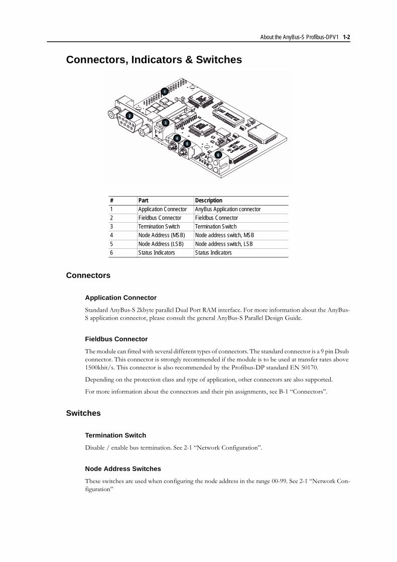
Connectors, Indicators & Switches
Connectors
Application Connector
Standard AnyBus-S 2kbyte parallel Dual Port RAM interface. For more information about the AnyBus-S application connector, please consult the general AnyBus-S Parallel Design Guide.
Fieldbus Connector
The module can fitted with several different types of connectors. The standard connector is a 9 pin Dsub connector. This connector is strongly recommended if the module is to be used at transfer rates above 1500kbit/s. This connector is also recommended by the Profibus-DP standard EN 50170.
Depending on the protection class and type of application, other connectors are also supported.
For more information about the connectors and their pin assignments, see B-1 �Connectors�.
Switches
Termination Switch
Disable / enable bus termination. See 2-1 �Network Configuration�.
Node Address Switches
These switches are used when configuring the node address in the range 00-99. See 2-1 �Network Con-figuration�
# Part Description1 Application Connector AnyBus Application connector2 Fieldbus Connector Fieldbus Connector3 Termination Switch Termination Switch4 Node Address (MSB) Node address switch, MSB
5 Node Address (LSB) Node address switch, LSB6 Status Indicators Status Indicators
2
1
3
4
5
6

About the AnyBus-S Profibus-DPV1 1-3
Status Indicators
The module features four status leds and an additional Watchdog led.
The function of the Watchdog led is equal for all AnyBus-S modules, consult the AnyBus-S Design Guide for more information.
LED 1 - Acyclic Traffic
This led indicates that a DPV1 service is currently being executed.
LED 2 - Fieldbus ON-Line
This led indicates if the module is online on the fieldbus or not.
LED 3 - Fieldbus Off-line
This led indicates if the module is off-line and is thus the opposite compared to led 2.
LED 4 - Fieldbus Diagnostics
This led indicates certain faults on the fieldbus side.
Colour State Indicates:Green On A DPV1 request is currently being executed
Off No power on the moduleNo DPV1 request is currently being executed
Colour State Indicates:Green On Bus is online and data exchange is possible
Off Bus is not onlineno power on the module
Flashing, 1 Hz Clear mode
Colour State Indicates:Red On Bus is OFF-line
Off Bus is not OFF-lineNo power on the module
Colour State Indicates:Red Off No diagnostics present.
No power on the module.Flashing, 1 Hz Error in configuration data
Flashing, 2 Hz Error in parameter dataFlashing, 4 Hz Error in initialisation of the Profibus communication
ASIC
1 2
4 3
Chapter 2
Network Configuration
Before the module can be used on a Profibus-DP network some basic settings must be configured.
Baudrate
The baudrate on a Profibus-DP network is set during configuration from the master. The module fea-tures auto baudrate detection and the user does not have to configure the baudrate.
Supported baudrates:
1. 9.6 kbit/s
2. 19.2 kbit/s
3. 45.45 kbit/s
4. 93.75 kbit/s
5. 187.5 kbit/s
6. 500 kbit/s
7. 1.5 Mbit/s
8. 3 Mbit/s
9. 6 Mbit/s
10. 12 Mbit/s
Node Address
The node address can be configured either using the on board switches, or via mailbox commands. The switches can be used when selecting a node address in the range 00-99.
Address 100-127 is available via the mailbox command FB_APPL_SET_NODE_ADDRESS, see 4-6 �FB_APPL_SET_NODE_ADDRESS�.
Note: Node 126 is reserved for commissioning purposes and shall not be used for data exchange.
Termination
Each bus segment in a Profibus network must be terminated properly to ensure error-free operation.
If the module is used as the first or last node in a network, the termination switch has to be in ON po-sition. Otherwise the switch has to be in OFF position.
Note: If an external termination connector is used, the switch must be in OFF position.
Chapter 3
Software Overview
General
I/O Sizes
Max I/O length when AnyBus_INIT is used:328 bytes
Max I/O length when AnyBus_INIT and FB_INIT is used:376 bytes
Global Control Commands
The module supports the following global commands:
� FREEZE/UNFREEZE of inputs
Works according to the Profibus-DP specification
� SYNC/UNSYNC of outputs
Works according to the Profibus-DP specification
� CLEAR
How the module will handle the OUT-area when receiving a CLEAR command is configured in the FB_INIT command, message data word 5, bit 14-15. (See 4-2 �FB_INIT�)
Data Exchange
The master will read/write data every bus cycle. The amount of data copied each bus cycle is determined in the configuration phase of the fieldbus initialisation. The data will be exchanged via the I/O areas.
Application stopped
The application may enable the watchdog function in the module during initialisation. (Refer to the AnyBus_INIT telegram in the AnyBus-S Parallel Design Guide)
If this function is enabled and the application stops updating the watchdog register (application stopped) the bus will go off-line after the defined watchdog time and the on-line LED on the module will turn red.
This situation is considered fatal; there is no way to recover from it besides power cycling the module.

Software Overview 3-2
DPV1 Functionality
The DPV1 extension enables acyclic read/write operations between a Class 1/2 master and a DPV1 slave in parallel with the cyclic user data communication.
Supported Class 1 Services
The following Class 1 services are available:
� MSAC1_Read
The master reads a data block from the module.
� MSAC1_Write
The master writes a data block to the module
� MSAC1_Status
Transmission of a status message from the module to the master. The master does not acknowl-edge the receipt of the status message; therefore these messages can be overwritten.
Supported Class 2 Services
The following Class 2 services are available:
� MSAC2_InitiateEstablishment of a connection for acyclic data communication
� MSAC_Abort
Termination of a connection for acyclic data communication
� MSAC2_Read
The master reads a data block from the module
� MSAC2_Write
The master writes a data block from the module.
� MSAG2_Data_Transport
With this service the master both reads and writes data from/to the module during the same service cycle.
Addressing
The acyclic read/write services defined in DPV1 are slot- and index related. This means that Slot number and Index are used for addressing a desired data block.
It is possible for the application to configure if the data block should be accessed from the parameter area (DPRAM or Internal RAM) of the module or from the application.
If the module is configured to access data blocks from the application, the request from the master will be forwarded to the application via a so called spontaneous mailbox telegram. The application then has to create a mailbox response and send it back to the module.
The maximum response time for a C2 read/write request is specified in the GSD-file. If this time has elapsed and the master still has not received an answer from the module (application), a time-out will occur in the master and the connection will be terminated.
The module can handle up to 4 simultaneous active C2 connections.

Software Overview 3-3
MSAC1/MSAC2_Read, MSAC1/MSAC2_Write and MSAC2_DataTransport
The application can access data blocks (objects) in one three different ways dependent on how the ob-jects are mapped.
1. Default object mapping
2. Application specific object mapping
3. Transparent object mapping (Only possible if the module is initialised with FB_INIT)
In case 1 and 2, objects are located in the internal parameter area (DPRAM or/and RAM) of the module. In case 3, objects are located at the application side.
Default Object Mapping
By default the parameter area in the module is divided into data blocks of 32 bytes, where each data block is associated with a predefined Slot number. Index is used to address a byte position within the data block.
Example:
Byte 0-31 in the parameter area is associated with Slot number 0; Byte 32-63 is associated with Slot number 1, and so on.
If the DPV1-master would like to access byte 34 in the parameter area it sends a read or write request where Slot number =1 and Index =2.
Application Specific Object Mapping
In this case the application �connects� a Slot Number and an Index to an object that is located at a cer-tain position in the parameter area (DPRAM or/and RAM). When the master sends a Read, Write or a DataTransport request with this Slot Number and Index, it will gain access to the object.
Mapping of objects is performed with the mailbox command FB_APPL_MAP_PARAMETER_OBJECT. (See 4-30 �FB_APPL_MAP_PARAMETER_OBJECT�)
Byte Parameter Area Slot Index0 Object 0 (32 bytes) 0 01 0 12 0 2.. .. ..31 0 31
32 Object 1 (32 bytes) 1 033 1 134 1 2.. .. ..
63 1 31X Object Y (32 bytes) Y 0X+1 Y 1X+2 Y 2... ... ...
X+31 Y 31
Software Overview 3-4
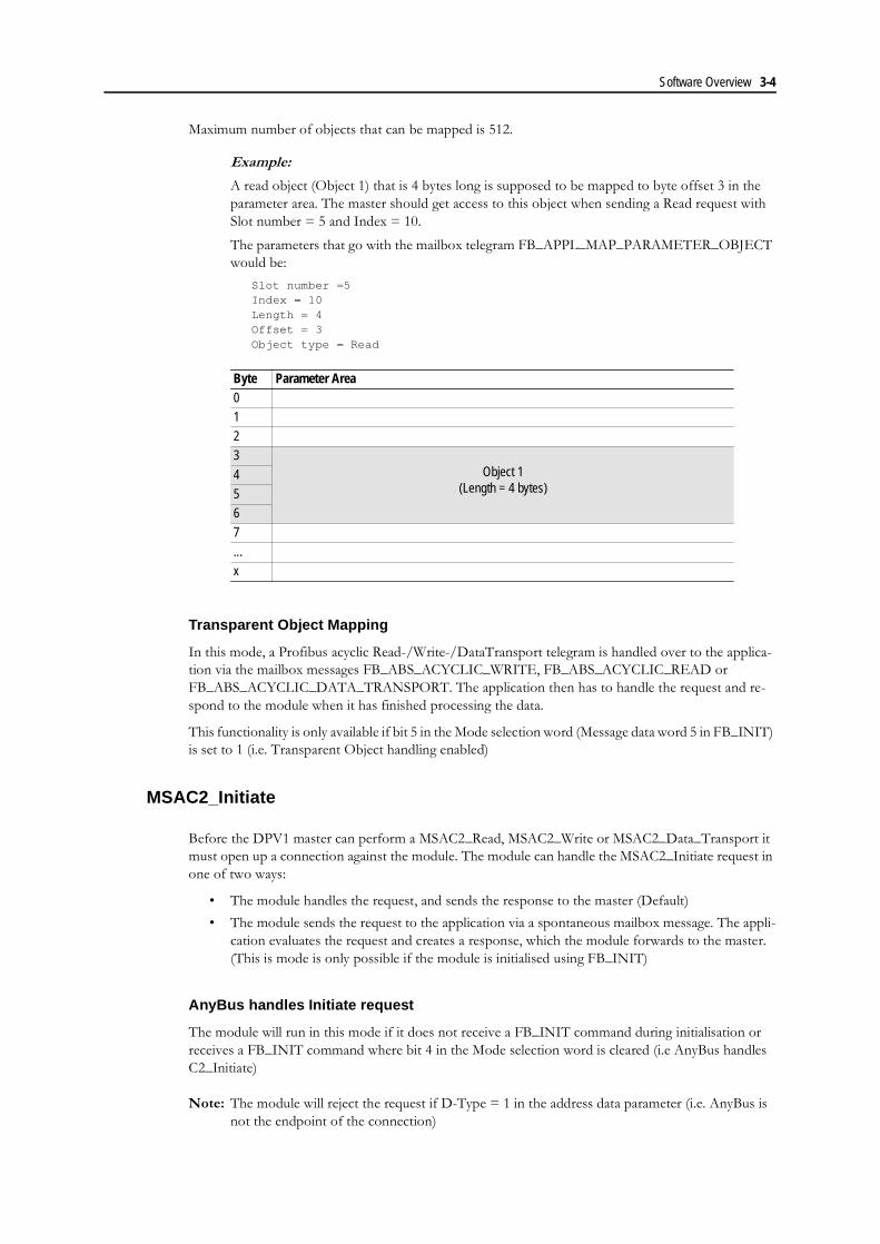
Maximum number of objects that can be mapped is 512.
Example:
A read object (Object 1) that is 4 bytes long is supposed to be mapped to byte offset 3 in the parameter area. The master should get access to this object when sending a Read request with Slot number = 5 and Index = 10.
The parameters that go with the mailbox telegram FB_APPL_MAP_PARAMETER_OBJECT would be:
Slot number =5Index = 10Length = 4Offset = 3Object type = Read
Transparent Object Mapping
In this mode, a Profibus acyclic Read-/Write-/DataTransport telegram is handled over to the applica-tion via the mailbox messages FB_ABS_ACYCLIC_WRITE, FB_ABS_ACYCLIC_READ or FB_ABS_ACYCLIC_DATA_TRANSPORT. The application then has to handle the request and re-spond to the module when it has finished processing the data.
This functionality is only available if bit 5 in the Mode selection word (Message data word 5 in FB_INIT) is set to 1 (i.e. Transparent Object handling enabled)
MSAC2_Initiate
Before the DPV1 master can perform a MSAC2_Read, MSAC2_Write or MSAC2_Data_Transport it must open up a connection against the module. The module can handle the MSAC2_Initiate request in one of two ways:
� The module handles the request, and sends the response to the master (Default)
� The module sends the request to the application via a spontaneous mailbox message. The appli-cation evaluates the request and creates a response, which the module forwards to the master. (This is mode is only possible if the module is initialised using FB_INIT)
AnyBus handles Initiate request
The module will run in this mode if it does not receive a FB_INIT command during initialisation or receives a FB_INIT command where bit 4 in the Mode selection word is cleared (i.e AnyBus handles C2_Initiate)
Note: The module will reject the request if D-Type = 1 in the address data parameter (i.e. AnyBus is not the endpoint of the connection)
Byte Parameter Area0123
Object 1(Length = 4 bytes)
4567
...x

Software Overview 3-5
Application handles Initiate request
The module will run in this mode if it has been initialised with FB_INIT where bit 4 in the Mode selec-tion word is set (i.e Application handles C2_Initiate).
In this mode, the C2-Initiate telegram will be handled over to the application via the mailbox message FB_ABS_ACYCLIC_INITIATE. The application then has to handle the request and send a response back to the module when it has finished the evaluation.
If the request is accepted, the application should clear Extended word 8.
MSAC2_Abort
The DPV1 master or DPV1 slave are using the service MSAC2_Abort to abort a MSAC2-connection. This is handled in two different ways, depending on how the module has been initialised.
� Master or AnyBus is initiating MSAC2_Abort
� Application is initiating a MSAC2_Abort
Master or AnyBus is initiating MSAC2_Abort
If bit 6 in the Mode selection word (See FB_INIT 4-2 �FB_INIT�) is set (1), the MSAC2_Abort tele-gram is handled over to the application via the mailbox message FB_ABS_ACYCLIC_ABORT_IND so that the application can determine the reason for the abortion.
The module will take care of closing the actual connection. (i.e. cancel all pending request and clean up allocated memory).
Note 1: The application must not respond to FB_ABS_ACYCLIC_ABORT_IND.
Note 2: The module will initiate a MSAC2_Abort if the application does not respond to a read, write or init request within the timeout time specified in FB_INIT.
Application is initiating a MSAC2_Abort
If bit 6 in the Mode selection word is clear (0), the application can cancel existing C2-connections using the mailbox command FB_APPL_ACYCLIC_ABORT
Software Overview 3-6
Start-up Communication
The master uses this telegram to identify itself with the module and to specify how the module should operate. The message is comprised of a series of octets (max 244). For the module to operate in DPV1 mode it has to be ensured that after the first seven bytes (specified in the DP-standard), three DPV1 status bytes are provided and that bit 7 in DPV1 Status_byte_1 is set.
Structure
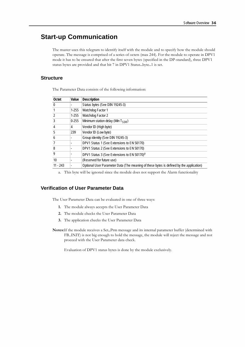
The Parameter Data consists of the following information:
Verification of User Parameter Data
The User Parameter Data can be evaluated in one of three ways:
1. The module always accepts the User Parameter Data
2. The module checks the User Parameter Data
3. The application checks the User Parameter Data
Notes:If the module receives a Set_Prm message and its internal parameter buffer (determined with FB_INIT) is not big enough to hold the message, the module will reject the message and not proceed with the User Parameter data check.
Evaluation of DPV1 status bytes is done by the module exclusively.
Octet Value Description0 - Status bytes (See DIN 19245-3)
1 1-255 Watchdog Factor 12 1-255 Watchdog Factor 23 0-255 Minimum station delay (Min TSDR)
4 4 Vendor ID (High byte)
5 239 Vendor ID (Low byte)6 - Group identity (See DIN 19245-3)7 - DPV1 Status 1 (See Extensions to EN 50170)8 - DPV1 Status 2 (See Extensions to EN 50170)
9 - DPV1 Status 3 (See Extensions to EN 50170)a
a. This byte will be ignored since the module does not support the Alarm functionality
10 - (Reserved for future use)11 - 243 - Optional User Parameter Data (The meaning of these bytes is defined by the application)
Software Overview 3-7
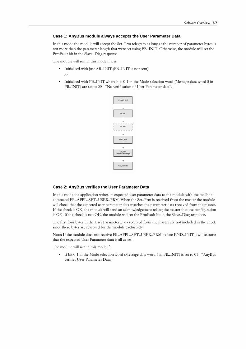
Case 1: AnyBus module always accepts the User Parameter Data
In this mode the module will accept the Set_Prm telegram as long as the number of parameter bytes is not more than the parameter length that were set using FB_INIT. Otherwise, the module will set the PrmFault bit in the Slave_Diag response.
The module will run in this mode if it is:
� Initialised with just AB_INIT (FB_INIT is not sent)
or
� Initialised with FB_INIT where bits 0-1 in the Mode selection word (Message data word 5 in FB_INIT) are set to 00 - �No verification of User Parameter data�.
Case 2: AnyBus verifies the User Parameter Data
In this mode the application writes its expected user parameter data to the module with the mailbox command FB_APPL_SET_USER_PRM. When the Set_Prm is received from the master the module will check that the expected user parameter data matches the parameter data received from the master. If the check is OK, the module will send an acknowledgement telling the master that the configuration is OK. If the check is not OK, the module will set the PrmFault bit in the Slave_Diag response.
The first four bytes in the User Parameter Data received from the master are not included in the check since these bytes are reserved for the module exclusively.
Note: If the module does not receive FB_APPL_SET_USER_PRM before END_INIT it will assume that the expected User Parameter data is all zeros.
The module will run in this mode if:
� If bit 0-1 in the Mode selection word (Message data word 5 in FB_INIT) is set to 01 - �AnyBus verifies User Parameter Data�
START_INIT
AB_INIT
FB_INIT
END_INIT
Set_Prm(Profibus message)
Usr_Prm OK

Software Overview 3-8
Case 3: Application verifies the User Parameter Data
When the Set_Prm telegram is received from the master the module will pass the User Parameter data over to the application via the FBS_ABS_VERIFY_USER_PRM mailbox command. The application then has to check the User Parameter data and reply back to the module if it was OK or not. If the ap-plication accepts the User Paramter data the module will send an acknowledgement telling the master that the User Parameter data is OK. If the application does not accept the User Parameter data, the mod-ule will set the PrmFault bit in the Slave_Diag response.
The module will run in this mode if..
� bit 0-1 in the Mode selection word (message data word 5 in FB_INIT) is set to 10 - �Application verifies User Parameter Data�.
START_INIT
AB_INIT
FB_INIT
FB_APPL_SET_EXPECTED_USR_PRM
END_INITSet_Prm(Profibus message)
CompareUsr_Prm
Usr_Prm OK Usr_Prm fault
Mismatch
Match
START_INIT
AB_INIT
FB_INIT
FB_ABS_VERIFY_USR_PRM(Mailbox message module-> Application)
END_INIT
Usr_Prm OK Usr_Prm fault
Set_Prm(Message from profibus master)
USR_PRM OK USR_PRM not OK
Software Overview 3-9
Check_Configuration telegram
General
After the Set_Parameter telegram, the master sends a Check_Configuration telegram to the slave. This event causes the slave to check its default configuration, determined at power-up against the actual con-figuration, specified in the master configuration. The module can be configured to do this check in one of three different ways. (3-9 �Verification of Configuration data�)
The module is a modular slave, which means that the size of the input/output block size is flexible and not tied to a specific block length. The input/output block is described by so-called Identifier bytes. Such a byte defines the input- and/or output data length as well as the data consistency.
The Identifier bytes are defined in the GSD-file and are automatically extracted by the configuration tool when you add the modules to your configuration.
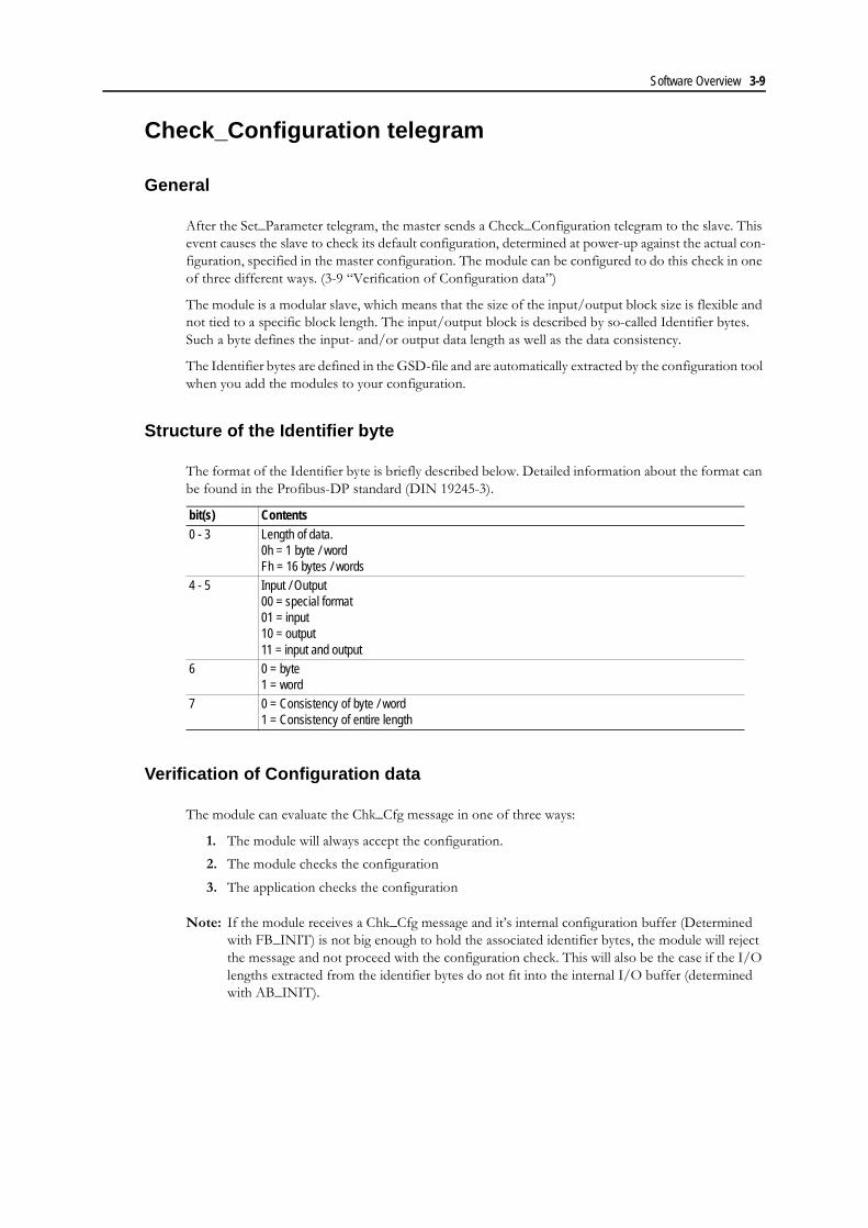
Structure of the Identifier byte
The format of the Identifier byte is briefly described below. Detailed information about the format can be found in the Profibus-DP standard (DIN 19245-3).
Verification of Configuration data
The module can evaluate the Chk_Cfg message in one of three ways:
1. The module will always accept the configuration.
2. The module checks the configuration
3. The application checks the configuration
Note: If the module receives a Chk_Cfg message and it�s internal configuration buffer (Determined with FB_INIT) is not big enough to hold the associated identifier bytes, the module will reject the message and not proceed with the configuration check. This will also be the case if the I/O lengths extracted from the identifier bytes do not fit into the internal I/O buffer (determined with AB_INIT).
bit(s) Contents0 - 3 Length of data.
0h = 1 byte / wordFh = 16 bytes / words
4 - 5 Input / Output00 = special format01 = input10 = output11 = input and output
6 0 = byte1 = word
7 0 = Consistency of byte / word1 = Consistency of entire length
Software Overview 3-10
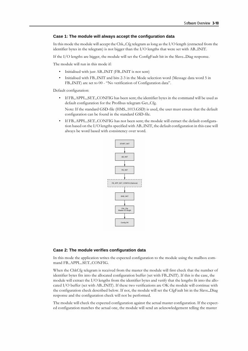
Case 1: The module will always accept the configuration data
In this mode the module will accept the Chk_Cfg telegram as long as the I/O length (extracted from the identifier bytes in the telegram) is not bigger than the I/O lengths that were set with AB_INIT.
If the I/O lengths are bigger, the module will set the ConfigFault bit in the Slave_Diag response.
The module will run in this mode if:
� Initialised with just AB_INIT (FB_INIT is not sent)
� Initialised with FB_INIT and bits 2-3 in the Mode selection word (Message data word 5 in FB_INIT) are set to 00 - �No verification of Configuration data�.
Default configuration:
� If FB_APPL_SET_CONFIG has been sent; the identifier bytes in the command will be used as default configuration for the Profibus telegram Get_Cfg.
Note: If the standard GSD-file (HMS_1013.GSD) is used, the user must ensure that the default configuration can be found in the standard GSD-file.
� If FB_APPL_SET_CONFIG has not been sent; the module will extract the default configura-tion based on the I/O lengths specified with AB_INIT, the default configuration in this case will always be word based with consistency over word.
Case 2: The module verifies configuration data
In this mode the application writes the expected configuration to the module using the mailbox com-mand FB_APPL_SET_CONFIG.
When the ChkCfg telegram is received from the master the module will first check that the number of identifier bytes fits into the allocated configuration buffer (set with FB_INIT). If this is the case, the module will extract the I/O lengths from the identifier bytes and verify that the lengths fit into the allo-cated I/O buffer (set with AB_INIT). If these two verifications are OK the module will continue with the configuration check described below. If not, the module will set the CfgFault bit in the Slave_Diag response and the configuration check will not be performed.
The module will check the expected configuration against the actual master configuration. If the expect-ed configuration matches the actual one, the module will send an acknowledgement telling the master
START_INIT
AB_INIT
FB_INIT
END_INIT
Config OK
Chk_CfgMaster I/O length
FB_APP_SET_CONFIG (Optional)

Software Overview 3-11
that the configuration is OK. If the configuration does not match, the module will set the CfgFault bit in the Slave_Diag response.
The module will run in this mode if:
� The module will run in this mode if bits 2-3 in the Mode selection word (Message data word 5 in FB_INIT) are set to 01 - �AnyBus Verifies Configuration Data�.
Default configuration:
� The identifier bytes in the mailbox will be used as default configuration for the Profibus telegram Get_Cfg.
Case 3: Application verifies the configuration data
When the ChkCfg telegram is received from the master the module will first check that the number of identifier bytes fits into the allocated configuration buffer (Set with FB_INIT). If this is the case, the module will extract the I/O lengths from the identifier bytes and verify that the lengths fit into the allo-cated I/O buffer (Set with AB_INIT). If these two verifications are OK the module will pass the iden-tifier bytes over to the application via the FB_ABS_VERIFY_CONFIG mailbox telegram. If not, the module will set the CfgFault bit in the Slave_Diag response and it will not send the mailbox to the ap-plication for further verification.
When the application receives this mailbox, it has to check the identifier bytes and respond to the mod-ule if the configuration is OK or not. If the application accepts the configuration the module will send an acknowledgement telling the master that the configuration is OK. If the application does not accept the configuration the module will set the CfgFault bit in the Slave_Diag response.
The module will run in this mode..
� If bits 2-3 in the Mode selection word (Message data word 5 in FB_INIT) are set to 10 - �Appli-cation verifies Configuration data�.
Default Configuration:
� If FB_APPL_SET_CONFIG is received; the identifier bytes in the mailbox will be used as de-fault configuration for the Profibus telegram Get_Cfg.
START_INIT
AB_INIT
FB_INIT
FB_APPL_SET_CONFIGAppl Identifier bytes (B)
END_INITChk_Cfg
Master Identifier bytes(A)
CompareIdentifier bytes
Config OK Config fault
A != B
A = B

Software Overview 3-12
� If FB_APPL_SET_CONFIG is not received; The module will extract the default configuration based on the I/O lengths that are specified in AB_INIT, the default configuration in this case will always be word based with consistency over word.
START_INIT
AB_INIT
FB_INIT
FB_ABS_VERIFY_CONFIG(Mailbox message module-> Application)
END_INIT
Config OK
Chk_CfgMaster Identifier bytes
Config Fault
FB_APPL_SET_CONFIG (Optional)
OK Not OK

Chapter 4
Mailbox Interface
This chapter describes the fieldbus specific mailbox commands in the module. Consult the AnyBus-S Design Guide for more information regarding mail box functionality.
Mailbox Commands initiated by the application
Mailbox Messages initiated by the module
Name DescriptionFB_INIT This mailbox command shall be sent to the module during the initial-
isation sequence and contains information required to initialise the module for Profibus specific functionalities.
FB_APPL_GET_USER_PRM This command is used for reading the actual User Parameter dataFB_WRITE_DIAGNOSTICS This command is used for sending diagnostic information to the
Profibus master.FB_APPL_SET_NODE_ADDRESS This command is used for setting the node address.
FB_APPL_SET_USER_PRM This mailbox is used for sending expected User Parameter data to the module to evaluate
FB_APPL_GET_NODE_ADDRESS This command is used for reading the currently used node addressFB_APPL_SET_CONFIG This mailbox is used for sending expected configuration data for the
module to evaluate.FB_APPL_GET_CONFIG This mailbox is used for reading out the configuration data.
FB_APPL_MAP_PARAMETER_OBJECT This mailbox is used for mapping DPV1 objects to the acyclic parameter area
FB_APPL_ACYCLIC_ABORT This command terminates a DPV1 class 2 connection.
Name DescriptionFB_ABS_VERIFY_USER_PRM This message is sent to the application for evaluation of the User
Parameter data.
FB_ABS_VERIFY_CONFIG This message is sent to the application for evaluation of the configu-ration data
FB_ABS_ACYCLIC_WRITE If the application has initialized the module to handle acyclic read/write requests in a transparent way, this mailbox will be send to the application whenever the module receives a DPV1 write request from the master.
FB_ABS_ACYCLIC_READ If the application has initialized the module to handle acyclic read/write requests in a transparent way, this mailbox will be sent to the application whenever the module receives a DPV1 request from the master.
FB_ABS_ACYCLIC_INITIATE The DPV1 C2-Initiate telegram will be sent to the application for ver-ification if the module is configured to do so.
FB_ABS_ACYCLIC_ABORT_IND The DPV1 C2-Abort telegram will be send to the application if the module is configured to do so.
FB_ABS_ACYCLIC_DATA_TRANSPORT This mailbox is used for sending expected configuration data for the module to evaluate.

4-2
Initialisation / Configuration
FB_INIT
Description
This command contains information required to initialise the module for Profibus specific functionali-ties.
Note: This command can only be sent after AnyBus_INIT, during module initialisation.
Command and response layout:
Parameter DescriptionCommand initiator ApplicationCommand Name FB_INITMessage type 02h
Command number 0001hFragmented NoExtended Header data Command: None
Response: Fault informationMessage data Command: Contains information required for Profibus specific functionalities.
Response: The command message data is returnedResponse message The response data is a copy of the command data.
Command Expected responseMessage ID (ID) (ID)
Message information 4002h 0002hCommand 0001h 0001h FB_INIT
Data size 0010h 0010h 10 bytes of data (5 words)
Frame count 0001h 0001hFrame number 0001h 0001h
Offset high 0000h 0000hOffset low 0000h 0000h
Extended word 1 - -Extended word 2 - -Extended word 3 - -Extended word 4 - -
Extended word 5 - -Extended word 6 - -Extended word 7 - -Extended word 8 - Fault information
Message dataword 1 Ident number Ident number (The response data
Message dataword 2 User parameter length User parameter length is a copy of theMessage dataword 3 Diagnostic length Diagnostic length command data)Message dataword 4 Configuration length Configuration lengthMessage dataword 5 Mode selection Mode selection
Message dataword 6 C1-length C1-lengthMessage dataword 7 C2-length C2-lengthMessage dataword 8 C2-Send Timeout C2-Send Timeout
4-3
Ident number
The Ident Number is an application specific number assigned by the PNO (Profibus User Organisation)
User Parameter length (in bytes)
Maximum amount of User Parameter data for the application. If this parameter is set to 0 (zero) the user parameter data functionality will be disabled. Valid settings range from 0 to 233.
User Parameter length = 0
The module will allocate 11 bytes of parameter data (7 bytes according to the DP-standard + 3PV1 status bytes + 1 AnyBus status byte)
User Parameter length > 0
The module will allocate 11 bytes described above + the number of bytes specified in the User Parameter length.
Diagnostic length (in bytes)
Maximum size of the Diagnostic Block structure for the application. If this parameter is set to 0 (zero) the diagnostic functionality will be disabled. Valid settings range from 0 to 238.
Diagnostic length = 0
The module will allocate 6 bytes of diagnostic data according to the DP-standard
Diagnostic length > 0
The module will allocate 6 bytes of diagnostic data according to the DP-standard + the number of bytes specified in the Diagnostic length.
Configuration length (in bytes)
Maximum amount of configuration data bytes (identifier bytes) for the application. Valid settings range from 0 to 244. If Configuration length = 0 the default value of 24 bytes will be used.
4-4
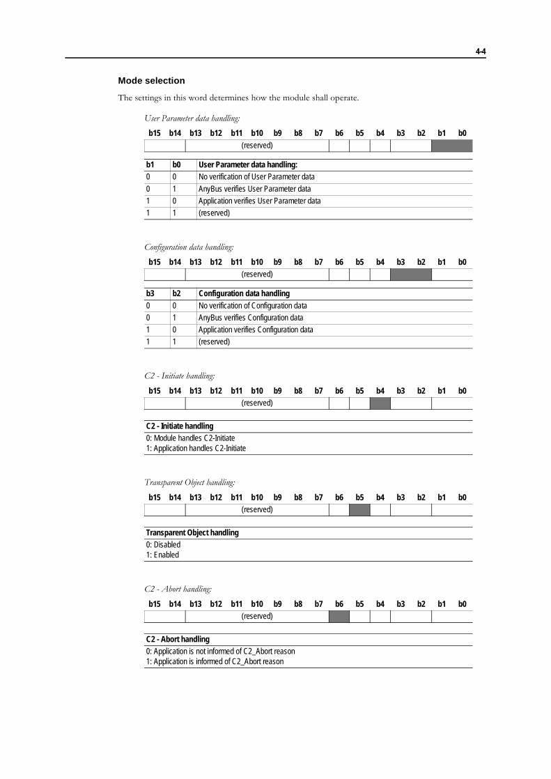
Mode selection
The settings in this word determines how the module shall operate.
User Parameter data handling:
Configuration data handling:
C2 - Initiate handling:
Transparent Object handling:
C2 - Abort handling:
b15 b14 b13 b12 b11 b10 b9 b8 b7 b6 b5 b4 b3 b2 b1 b0(reserved)
b1 b0 User Parameter data handling:0 0 No verification of User Parameter data
0 1 AnyBus verifies User Parameter data1 0 Application verifies User Parameter data1 1 (reserved)
b15 b14 b13 b12 b11 b10 b9 b8 b7 b6 b5 b4 b3 b2 b1 b0(reserved)
b3 b2 Configuration data handling0 0 No verification of Configuration data0 1 AnyBus verifies Configuration data1 0 Application verifies Configuration data1 1 (reserved)
b15 b14 b13 b12 b11 b10 b9 b8 b7 b6 b5 b4 b3 b2 b1 b0(reserved)
C2 - Initiate handling0: Module handles C2-Initiate1: Application handles C2-Initiate
b15 b14 b13 b12 b11 b10 b9 b8 b7 b6 b5 b4 b3 b2 b1 b0(reserved)
Transparent Object handling0: Disabled1: Enabled
b15 b14 b13 b12 b11 b10 b9 b8 b7 b6 b5 b4 b3 b2 b1 b0(reserved)
C2 - Abort handling0: Application is not informed of C2_Abort reason1: Application is informed of C2_Abort reason

4-5
Output action when Global command CLEAR is received from the Master:
C1-length (in bytes)
Specifies the maximum number of data bytes allowed for a C1 read/write request. Valid settings range from 0 to 240. The module will set up its internal C1-buffer based on this value + 4 bytes of header data. I.e C1-buffer length = C1-length + 4 (C1 buffer length range = 4 to 244)
C2-length (in bytes)
Specifies the maximum number of data bytes allowed for a C2 read/write request. Valid settings range from 0 to 240. The module will set up its internal C2-buffer based on this value + 4 bytes of header data. I.e C2-buffer length = C2-length + 4 (C2 buffer length range = 4 to 244)
If the C2-buffer length is less than 20 bytes, it will be adjusted to 20 bytes.
C2-Send Timeout (Timebase = 10ms, e.g a value of 100 equals 1 second)
Valid settings range from 1 to 32767. If a value of 0 (zero) is given, the default value of 1 second will be used.
This value specifies the performance of a DPV1 device. The value has to be larger than the max-imum processing time in the application. The value should be as low as possible, and shall ac-cording to the DPV1 standard not exceed the following values:
Fault Information
When a mailbox command cannot be processed the Message Information register in the header of the response will indicate that an error occurred. Consult the AnyBus-S Design Guide for more information
If the error code is �Undefined ERROR� (Fh), extended error information is available in the Fault Infor-mation register (Extended word 8).
The fault codes in the Fault Information register are:
b15 b14 b13 b12 b11 b10 b9 b8 b7 b6 b5 b4 b3 b2 b1 b0(reserved)
b15 b14 Action0 0 Out-area cleared (0)0 1 Out-area freeze
1 0 Out-area set (1)1 1 (reserved)
Baudrate in kbaud <= 187.5 500 1500 3000 6000 12000C2-Send Timeout in seconds 4 2 1 1 1 1
Register Value Description0031h Not enough memory in the Profibus communication controller0033h Invalid Input/Output data length0034h Invalid Diagnostics data length0035h Invalid User Parameter data length
0036h Invalid Configuration data length0021h Invalid C2-length0024h Invalid C1-length000Ch Invalid C2-Send timeout000Dh Invalid Mode selection setting

4-6
FB_APPL_SET_NODE_ADDRESS
Description
This command is used to change the network node address of the module.
Address range: 0 - 126
Note: This command can only be sent during module initialisation.
Command and response layout:
Parameter DescriptionCommand initiator ApplicationCommand Name FB_APPL_SET_NODE_ADDRESSMessage type 02hCommand number 0004h
Fragmented NoExtended Header data Command: None
Response: Fault informationMessage data Command: Contains the node address (0 - 126)
Response: The command message data is returnedResponse message If the command was not accepted the reason for the rejection is indicated in
the Message information wqord. If the message information indicates “Unde-fined Error” further fault information is available in Extended word 8. No Mes-sage data will be returned.
Command Expected responseMessage ID (ID) (ID)
Message information 4002h 0002hCommand 0004h 0004h FB_APPL_SET_NODE_ADDRESS
Data size 0002h 0000h
Frame count 0001h 0001hFrame number 0001h 0001h
Offset high 0000h 0000hOffset low 0000h 0000h
Extended word 1 - -Extended word 2 - -Extended word 3 - -Extended word 4 - -
Extended word 5 - -Extended word 6 - -Extended word 7 - -Extended word 8 - Fault information
Message dataword 1 Node address Node address

4-7
FB_APPL_GET_NODE_ADDRESS
Description
This command returns the currently used node address of the module.
Command and response layout:
Parameter DescriptionCommand initiator ApplicationCommand Name FB_APPL_GET_NODE_ADDRESSMessage type 02hCommand number 0006h
Fragmented NoExtended Header data Command: None
Response: NoneMessage data Command: None
Response: The response holds the currently used node address.Response message If the command is not accepted the reason for the rejection is indicated in the
Message Information word.
Command Expected responseMessage ID (ID) (ID)
Message information 4002h 0002hCommand 0006h 0006h FB_APPL_GET_NODE_ADDRESS
Data size 0002h 0000hFrame count 0001h 0001h
Frame number 0001h 0001hOffset high 0000h 0000hOffset low 0000h 0000h
Extended word 1 - -
Extended word 2 - -Extended word 3 - -Extended word 4 - -Extended word 5 - -Extended word 6 - -
Extended word 7 - -Extended word 8 - -
Node address Message dataword 1

4-8
Parameter Data
FB_ABS_VERIFY_USER_PRM
Description
This mailbox message can be sent to the application whenever the module receives a Set_Prm message from the Profibus master. The application must evaluate the User Parameter data and send a positive or negative response to the module. If the response is negative the Set_Prm telegram will be rejected and the PrmFault bit will be set in the Slave_Diag response.
This procedure will only be carried out if bit 0-1 in the Mode selection word (Message data word 5 in FB_INIT) is set to b10 - Application verifies User Parameter data.
Note: The first four bytes (DPV1 status bytes + AnyBus status byte) of User Parameter data will not be sent to the application as these bytes are reserved for the module exclusively.
Command and response layout:
Parameter DescriptionCommand initiator ModuleCommand Name FB_ABS_VERIFY_USER_PRMMessage type 02hCommand number 0007h
Fragmented NoExtended Header data Command: None
Response: Fault informationMessage data Command: User Parameter data (Excluding DPV1- and AnyBus status
bytes)Response: None
Response message If the application finds the User Parameter data to be correct, it should clear (0) bit 0 in the Fault Information word (Extended word 8). If the application finds the User Parameter data to be incorrect, it should set (1) bit 0 in the Fault information word (Extended word 8)
Command Expected responseMessage ID (ID) (ID)
Message information 4002h 0002hCommand 0007h 0007h FB_ABS_VERIFY_USER_PRM
Data size (User Parameter data size) 0000hFrame count 0001h 0001h
Frame number 0001h 0001hOffset high 0000h 0000h
Offset low 0000h 0000hExtended word 1 - -Extended word 2 - -Extended word 3 - -Extended word 4 - -
Extended word 5 - -Extended word 6 - -Extended word 7 - -Extended word 8 - Fault Information Fault Information
Message data User Parameter data

4-9
FB_APPL_GET_USER_PRM
Description
With this mailbox command the application can read out the User parameter data buffer.
This telegram will only be accepted after a successful END_INIT.
Note 1: The module will reject this command if the application sends it before the module has received the Set_Prm telegram from the master. An error code in Extended word 8 of the response will indicate this.
Note 2: The first four bytes (DPV1 status bytes + AnyBus status byte) of User Parameter data will not be sent to the application as these bytes are reserved for the module exclusively.
Command and response layout:
Parameter DescriptionCommand initiator ApplicationCommand Name FB_ABS_GET_USER_PRMMessage type 02hCommand number 0002h
Fragmented NoExtended Header data Command: None
Response: NoneMessage data Command: None
Response: User Parameter DataResponse message If the command is rejected the reason is indicated in the Message informa-
tion word.
Command Expected responseMessage ID (ID) (ID)
Message information 4002h 0002hCommand 0002h 0002h FB_APPL_GET_USER_PRM
Data size 0000h (User parameter data size)Frame count 0001h 0001h
Frame number 0001h 0001hOffset high 0000h 0000hOffset low 0000h 0000h
Extended word 1 - -
Extended word 2 - -Extended word 3 - -Extended word 4 - -Extended word 5 - -
Extended word 6 - -Extended word 7 - -Extended word 8 - Fault Information Fault Information
User Parameter data
4-10
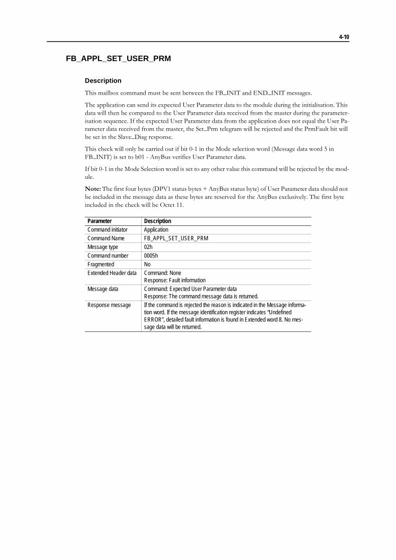
FB_APPL_SET_USER_PRM
Description
This mailbox command must be sent between the FB_INIT and END_INIT messages.
The application can send its expected User Parameter data to the module during the initialisation. This data will then be compared to the User Parameter data received from the master during the parameter-isation sequence. If the expected User Parameter data from the application does not equal the User Pa-rameter data received from the master, the Set_Prm telegram will be rejected and the PrmFault bit will be set in the Slave_Diag response.
This check will only be carried out if bit 0-1 in the Mode selection word (Message data word 5 in FB_INIT) is set to b01 - AnyBus verifies User Parameter data.
If bit 0-1 in the Mode Selection word is set to any other value this command will be rejected by the mod-ule.
Note: The first four bytes (DPV1 status bytes + AnyBus status byte) of User Parameter data should not be included in the message data as these bytes are reserved for the AnyBus exclusively. The first byte included in the check will be Octet 11.
Parameter DescriptionCommand initiator ApplicationCommand Name FB_APPL_SET_USER_PRMMessage type 02h
Command number 0005hFragmented NoExtended Header data Command: None
Response: Fault informationMessage data Command: Expected User Parameter data
Response: The command message data is returned.Response message If the command is rejected the reason is indicated in the Message informa-
tion word. If the message identification register indicates “Undefined ERROR”, detailed fault information is found in Extended word 8. No mes-sage data will be returned.

4-11
Command and response layout:
Command Expected responseMessage ID (ID) (ID)
Message information 4002h 0002hCommand 0005h 0005h FB_ABS_SET_USER_PRM
Data size (User Parameter data size) (User Parameter data size) Size = User parameter data sizeFrame count 0001h 0001h
Frame number 0001h 0001hOffset high 0000h 0000hOffset low 0000h 0000h
Extended word 1 - -Extended word 2 - -Extended word 3 - -Extended word 4 - -
Extended word 5 - -Extended word 6 - -Extended word 7 - -Extended word 8 - Fault Information Fault Information
Message data User Parameter data User Parameter data

4-12
Configuration Data
FB_ABS_VERIFY_CONFIG
Description
This mailbox telegram can be sent to the application when the module receives a Chk_Cfg telegram from the Profibus master. The application must then evaluate the configuration data (identifier bytes) and send a positive or negative response to the module. If the response is negative the Chk_Cfg telegram will be rejected and the Cfg_Fault bit will be set in the Diagnostic message response.
This check will only be carried out if bit 2-3 in the Mode selection word (Message data word 5 in FB_INIT) is set to b10 - Application verifies Configuration data.
Command and response layout:
Parameter DescriptionCommand initiator ModuleCommand Name FB_ABS_VERIFY_CONFIGMessage type 02h
Command number 0008hFragmented NoExtended Header data Command: None
Response: Fault informationMessage data Command: Configuration data
Response: The command message data is returned.Response message If the application finds the configuration to be correct, it should clear (0) bit 0
in the Fault information register (Extended word 8)If the application finds the configuration to be correct, it should set (1) bit 0 in the Fault information register (Extended word 8)
Command Expected responseMessage ID (ID) (ID)
Message information 4002h 0002h
Command 0008h 0008h FB_ABS_VERIFY_CONFIGData size (Configuration data size) 0000h
Frame count 0001h 0001hFrame number 0001h 0001h
Offset high 0000h 0000h
Offset low 0000h 0000hExtended word 1 - -Extended word 2 - -Extended word 3 - -
Extended word 4 - -Extended word 5 - -Extended word 6 - -Extended word 7 - -
Extended word 8 - Fault Information Fault Information
Message data Configuration data
4-13
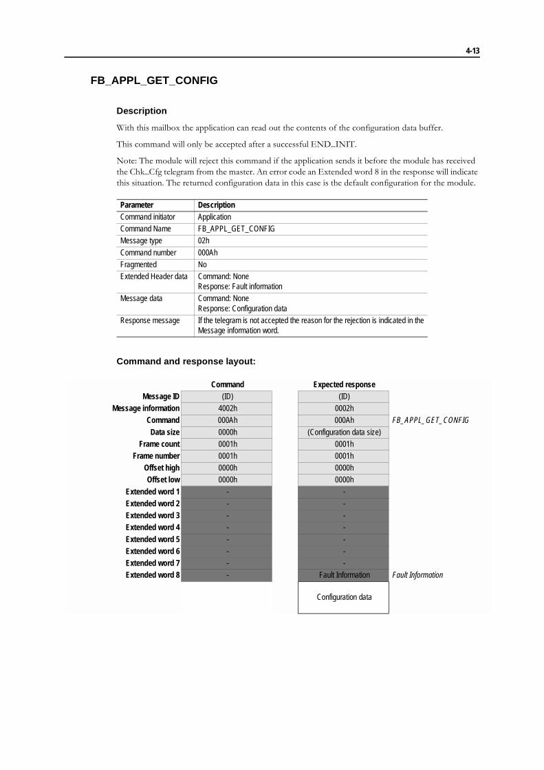
FB_APPL_GET_CONFIG
Description
With this mailbox the application can read out the contents of the configuration data buffer.
This command will only be accepted after a successful END_INIT.
Note: The module will reject this command if the application sends it before the module has received the Chk_Cfg telegram from the master. An error code an Extended word 8 in the response will indicate this situation. The returned configuration data in this case is the default configuration for the module.
Command and response layout:
Parameter DescriptionCommand initiator ApplicationCommand Name FB_APPL_GET_CONFIGMessage type 02h
Command number 000AhFragmented NoExtended Header data Command: None
Response: Fault informationMessage data Command: None
Response: Configuration dataResponse message If the telegram is not accepted the reason for the rejection is indicated in the
Message information word.
Command Expected responseMessage ID (ID) (ID)
Message information 4002h 0002hCommand 000Ah 000Ah FB_APPL_GET_CONFIG
Data size 0000h (Configuration data size)Frame count 0001h 0001h
Frame number 0001h 0001hOffset high 0000h 0000hOffset low 0000h 0000h
Extended word 1 - -Extended word 2 - -Extended word 3 - -Extended word 4 - -
Extended word 5 - -Extended word 6 - -Extended word 7 - -Extended word 8 - Fault Information Fault Information
Configuration data
4-14
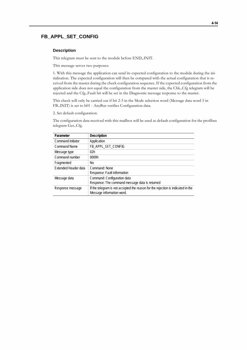
FB_APPL_SET_CONFIG
Description
This telegram must be sent to the module before END_INIT.
This message serves two purposes:
1. With this message the application can send its expected configuration to the module during the ini-tialisation. The expected configuration will then be compared with the actual configuration that is re-ceived from the master during the check configuration sequence. If the expected configuration from the application side does not equal the configuration from the master side, the Chk_Cfg telegram will be rejected and the Cfg_Fault bit will be set in the Diagnostic message response to the master.
This check will only be carried out if bit 2-3 in the Mode selection word (Message data word 5 in FB_INIT) is set to b01 - AnyBus verifies Configuration data.
2. Set default configuration:
The configuration data received with this mailbox will be used as default configuration for the profibus telegram Get_Cfg.
Parameter DescriptionCommand initiator ApplicationCommand Name FB_APPL_SET_CONFIGMessage type 02hCommand number 0009h
Fragmented NoExtended Header data Command: None
Response: Fault informationMessage data Command: Configuration data
Response: The command message data is returnedResponse message If the telegram is not accepted the reason for the rejection is indicated in the
Message information word.
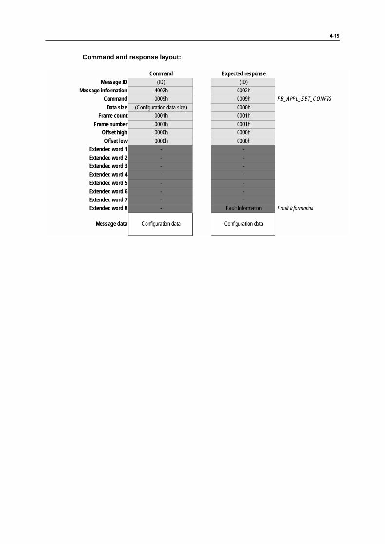
4-15
Command and response layout:
Command Expected responseMessage ID (ID) (ID)
Message information 4002h 0002hCommand 0009h 0009h FB_APPL_SET_CONFIG
Data size (Configuration data size) 0000hFrame count 0001h 0001h
Frame number 0001h 0001hOffset high 0000h 0000hOffset low 0000h 0000h
Extended word 1 - -Extended word 2 - -Extended word 3 - -Extended word 4 - -
Extended word 5 - -Extended word 6 - -Extended word 7 - -Extended word 8 - Fault Information Fault Information
Message data Configuration data Configuration data

4-16
Diagnostics
FB_APPL_WRITE_DIAGNOSTICS
Description
This telegram can only be sent to the module after END_INIT.
The maximum size of the Diagnostic data is defined in FB_INIT.
Parameter DescriptionCommand initiator Application
Command Name FB_APPL_WRITE_DIAGNOSTICSMessage type 02hCommand number 0003hFragmented NoExtended Header data Command: Service code (See description below)
Response: Fault informationMessage data Command: Diagnostic data
Response: The command message data is returnedResponse message If the telegram is not accepted the reason for the rejection is indicated in the
Message information word.

4-17
Command and response layout:
Service Code (Low byte of Extended word 8)
In this byte the application can control the Ext_Diag, Ext_Diag_Overflow and Static_Diag bits in the Standard diagnostic bytes (Station_Status_1 - 3).
Ext_Diag (Bit 0):
0: Low priority message; If the diagnostics are considered as status information there will be no notifi-cation in the diagnostic overview, but the PLC/host program can still evaluate the status information.
1: High priority message; If the diagnostics are considered high-priority, the user will be informed of the (error-) situation in the diagnostic overview on the master side. (The PLC/host porgoram can ghen , for example, cal a special error routine) When there is no high-priority diagnostics pending any longer, the application must update the diagnostics as Low-priority to clear the Ext_diag bit in the master.
Command Expected responseMessage ID (ID) (ID)
Message information 4002h 0002hCommand 0003h 0003h FB_APPL_WRITE_DIAGNOSTICS
Data size (Diagnostic data size) 0000hFrame count 0001h 0001h
Frame number 0001h 0001hOffset high 0000h 0000hOffset low 0000h 0000h
Extended word 1 - / Service code -Extended word 2 - -Extended word 3 - -Extended word 4 - -
Extended word 5 - -Extended word 6 - -Extended word 7 - -Extended word 8 - Fault Information Fault Information
Message data Diagnostic data Diagnostic data

4-18
Acyclic Data Functions
General
The Extended header data in the response message contains the following parameters
• Slot NumberMeaning:Parameter for addressing
Range: 0-254 (255 is reserved)
• Index
Meaning:Parameter for addressing
Range: 0-254 (255 is reserved)
• LengthMeaning:Number of data bytes to read/write
Range: 0-240
• SAP Number
Meaning: SAP (Service Access Point) for the acyclic request. With this information the applica-tion can determine if a Class 1 or Class 2 master issued the Read/Write
For a Class 1 connection SAP 51 (50) is permanently used.
For a Class 2 connection SAP�s 45-48 are used in decreasing sequence, starting with SAP 48. (The module supports a maximum of 4 simultaneous active C2 connections)

4-19
Error Codes
Octet b15 b14 b13 b12 b11 b10 b9 b8Error_Code_1 Error Class Error Code
Octet b7 b6 b5 b4 b3 b2 b1 b0Error_Code_2 User Specific
Error Class Meaning Error Code0 - 9 (reserved) -10 Application 0
12
3-789
10-15
= Read error= Write error= Module error= (reserved)= Version conflict= Feature not supported= User Specific
11 Access 0123456789
10 - 15
= Invalid index= Write length error= Invalid slot= Type conflict= Invalid area= State conflic= Access denied= Invalid range= Invalid parameter= Invalid type= User Specific
12 Resource 0123
4 - 78 - 15
= Read constrain conflict= Write constrain conflict= Resource busy= Resource unavailable= (reserved)= User Specific
13 - 15 User Specific - = User Specific

4-20
FB_ABS_ACYCLIC_WRITE
Description
Command and response layout:
Parameter DescriptionCommand initiator ModuleCommand Name FB_ABS_ACYCLIC_WRITEMessage type 02hCommand number 000Ch
Fragmented NoExtended Header data Command: Extended word 1 contains the number of objects to map (max 42)
Response: Fault informationMessage data Command: Write data
Response: NoneResponse message none
Command Expected responseMessage ID (ID) (ID)
Message information 4002h 0002hCommand 000Ch 000Ch FB_ABS_ACYCLIC_WRITE
Data size (data size) 0000h Number of bytes to writeFrame count 0001h 0001h
Frame number 0001h 0001hOffset high 0000h 0000hOffset low 0000h 0000h
Extended word 1 - -Extended word 2 - -
Extended word 3 - -Extended word 4 - -Extended word 5 SAP-number -Extended word 6 Slot number -
Extended word 7 Index -Extended word 8 Length Fault information DPV1 specific fault information
Message data Write data

4-21
FB_ABS_ACYCLIC_READ
Description
Command and response layout:
Parameter DescriptionCommand initiator ModuleCommand Name FB_ABS_ACYCLIC_READMessage type 02hCommand number 000Dh
Fragmented NoExtended Header data Command: Slot number, Index, Length and SAP-number
Response: Error Code1, Error Code2Message data Command: None
Response: Read dataResponse message none
Command Expected responseMessage ID (ID) (ID)
Message information 4002h 0002hCommand 000Dh 000Dh FB_ABS_ACYCLIC_READ
Data size 0000h (data size) Number of bytes to readFrame count 0001h 0001h
Frame number 0001h 0001hOffset high 0000h 0000hOffset low 0000h 0000h
Extended word 1 - -Extended word 2 - -
Extended word 3 - -Extended word 4 - -Extended word 5 SAP-number -Extended word 6 Slot number -
Extended word 7 Index -Extended word 8 Length ErrorCode 1, ErrorCode 2 DPV1 specific fault information
Read data Response data
4-22
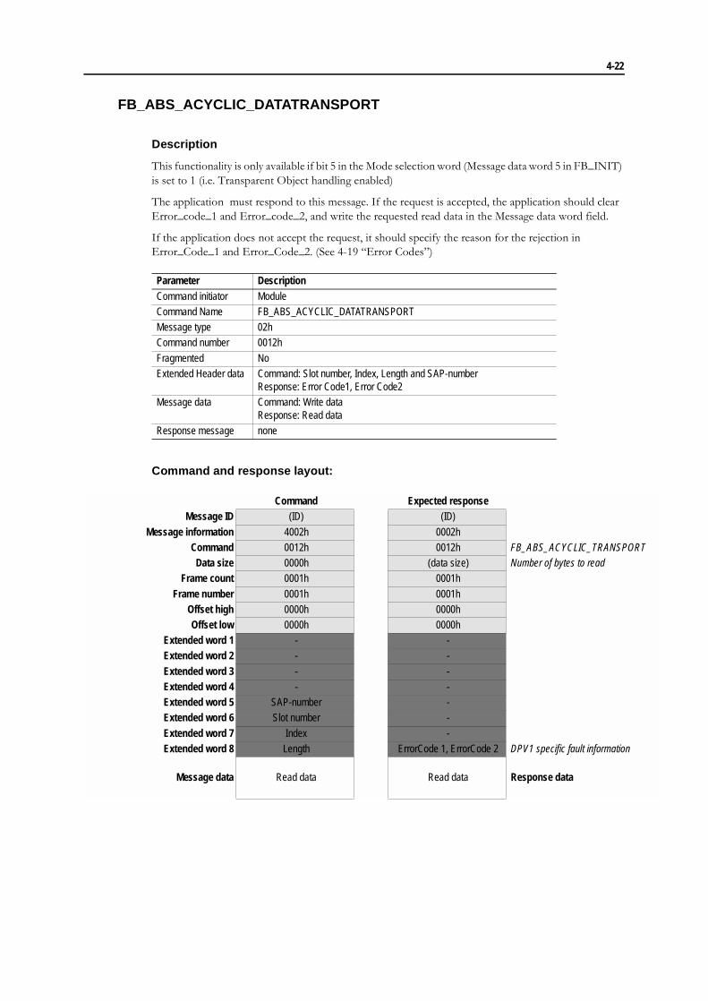
FB_ABS_ACYCLIC_DATATRANSPORT
Description
This functionality is only available if bit 5 in the Mode selection word (Message data word 5 in FB_INIT) is set to 1 (i.e. Transparent Object handling enabled)
The application must respond to this message. If the request is accepted, the application should clear Error_code_1 and Error_code_2, and write the requested read data in the Message data word field.
If the application does not accept the request, it should specify the reason for the rejection in Error_Code_1 and Error_Code_2. (See 4-19 �Error Codes�)
Command and response layout:
Parameter DescriptionCommand initiator ModuleCommand Name FB_ABS_ACYCLIC_DATATRANSPORTMessage type 02hCommand number 0012h
Fragmented NoExtended Header data Command: Slot number, Index, Length and SAP-number
Response: Error Code1, Error Code2Message data Command: Write data
Response: Read dataResponse message none
Command Expected responseMessage ID (ID) (ID)
Message information 4002h 0002hCommand 0012h 0012h FB_ABS_ACYCLIC_TRANSPORT
Data size 0000h (data size) Number of bytes to readFrame count 0001h 0001h
Frame number 0001h 0001hOffset high 0000h 0000hOffset low 0000h 0000h
Extended word 1 - -Extended word 2 - -
Extended word 3 - -Extended word 4 - -Extended word 5 SAP-number -Extended word 6 Slot number -
Extended word 7 Index -Extended word 8 Length ErrorCode 1, ErrorCode 2 DPV1 specific fault information
Message data Read data Read data Response data

4-23
FB_ABS_ACYCLIC_INITIATE
Description
Command and response layout:
Parameter DescriptionCommand initiator ModuleCommand Name FB_ABS_ACYCLIC_INITIATEMessage type 02hCommand number 000Fh
Fragmented NoExtended Header data Command: SAP-number used for this connection
Response: Error Code1, Error Code2Message data Command: Master Initiate parameters
Response: Slave Initiate parametersResponse message none
Command Expected responseMessage ID (ID) (ID)
Message information 4002h 0002hCommand 000Fh 000Fh FB_ABS_ACYCLIC_INITIATE
Data size 12 + S_length+D_length 10 + S_length+D_length Data sizeFrame count 0001h 0001h
Frame number 0001h 0001hOffset high 0000h 0000hOffset low 0000h 0000h
Extended word 1 - -Extended word 2 - -
Extended word 3 - -Extended word 4 - -Extended word 5 - -Extended word 6 - -
Extended word 7 - -Extended word 8 SAP-number ErrorCode 1, ErrorCode 2 DPV1 specific fault information
Message databyte 1 Send Timeout (word) Features supported 1 Response dataMessage databyte 2 Features supported 1Message databyte 3 Features supported 1 Profile Ident Number
Message databyte 4 Features supported 2Message databyte 5 Profile ident number S_TypeMessage databyte 6 S_LengthMessage databyte 7 D_Type S_Address
Size of s_address=s_lengthMessage databyte 8 D_LengthMessage databyte 9 S_Address
Size of S_address=S_lengthD_Address
Size of d_address=d_lengtMessage databyte 10Message databyte 11 D_Address
Size of d_address=d_lengtMessage databyte 12
4-24
Send Timeout
During this time the master has to fetch the response data provided by the module.
Features supported 1 & 2
Identifies the supported C2-service functionality.
Features supported 1:
Bit 0: DPV1_RW - This bit is set if the services C2_Read and C2_Write are supported.
Bit 1-7: (reserved)
Features supported 2:
Bit 0-7: (reserved)
Profile features supported 1 & 2
Identifies the supported service functionality regarding the used profile definition. The meaning of the defined bits is profile or vendor specific.
Profile features supported 1:
Bit 0-7: Defined by the profile.
Profile features supported 2:
Bit 0-7: Defined by the profile.
Profile Ident number
By means of this parameter a unique profile definition is identified. The Profile Ident Number will be taken from the pool of Ident Numbers handled by PNO.
S_Type & S_Length
S_Type
This parameter indicates the presence of the optional Network/MAC address of the source
Bit 0: This bit is set to one if a Network/MAC address is present in parameter S_Address (See below). If this bit is set to 0 (zero) it means that the source is the endpoint of the connection.
Bit 1-7: (reserved)
S_Length:
This parameter indicate the length of the S_Address parameter (See below)
D_type & D_length
D_Type
This parameter indicates the presence of the optional Network/MAC address of the destination.
Bit 0: This bit is set to one if a Network/MAC address is present in parameter D_Address (See below). If this bit is set to 0 (zero) it means that the source is the endpoint of the connection.
Bit 1-7: (reserved)
D_Length:
This parameter indicate the length of the D_Address parameter (See below)
4-25
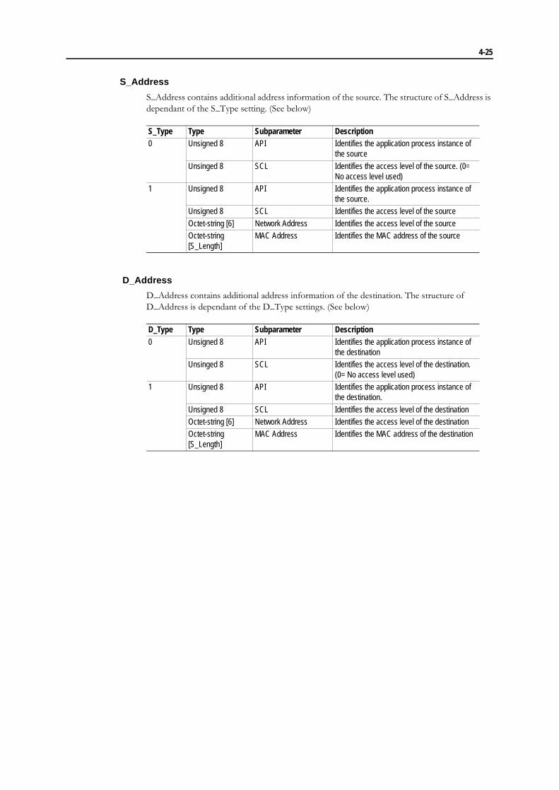
S_Address
S_Address contains additional address information of the source. The structure of S_Address is dependant of the S_Type setting. (See below)
D_Address
D_Address contains additional address information of the destination. The structure of D_Address is dependant of the D_Type settings. (See below)
S_Type Type Subparameter Description0 Unsigned 8 API Identifies the application process instance of
the source
Unsinged 8 SCL Identifies the access level of the source. (0= No access level used)
1 Unsigned 8 API Identifies the application process instance of the source.
Unsigned 8 SCL Identifies the access level of the source
Octet-string [6] Network Address Identifies the access level of the sourceOctet-string [S_Length]
MAC Address Identifies the MAC address of the source
D_Type Type Subparameter Description0 Unsigned 8 API Identifies the application process instance of
the destinationUnsinged 8 SCL Identifies the access level of the destination.
(0= No access level used)1 Unsigned 8 API Identifies the application process instance of
the destination.
Unsigned 8 SCL Identifies the access level of the destinationOctet-string [6] Network Address Identifies the access level of the destinationOctet-string [S_Length]
MAC Address Identifies the MAC address of the destination
4-26
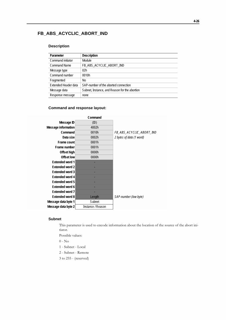
FB_ABS_ACYCLIC_ABORT_IND
Description
Command and response layout:
Subnet
This parameter is used to encode information about the location of the source of the abort ini-tiator.
Possible values:
0 - No
1 - Subnet - Local
2 - Subnet - Remote
3 to 255 - (reserved)
Parameter DescriptionCommand initiator ModuleCommand Name FB_ABS_ACYCLIC_ABORT_INDMessage type 02hCommand number 0010h
Fragmented NoExtended Header data SAP-number of the aborted connectionMessage data Subnet, Instance, and Reason for the abortionResponse message none
CommandMessage ID (ID)
Message information 4002h
Command 0010h FB_ABS_ACYCLIC_ABORT_INDData size 0002h 2 bytes of data (1 word)
Frame count 0001hFrame number 0001h
Offset high 0000hOffset low 0000h
Extended word 1 -Extended word 2 -Extended word 3 -
Extended word 4 -Extended word 5 -Extended word 6 -Extended word 7 -
Extended word 8 Length SAP-number (low byte)Message data byte 1 SubnetMessage data byte 2 Instance / Reason
4-27
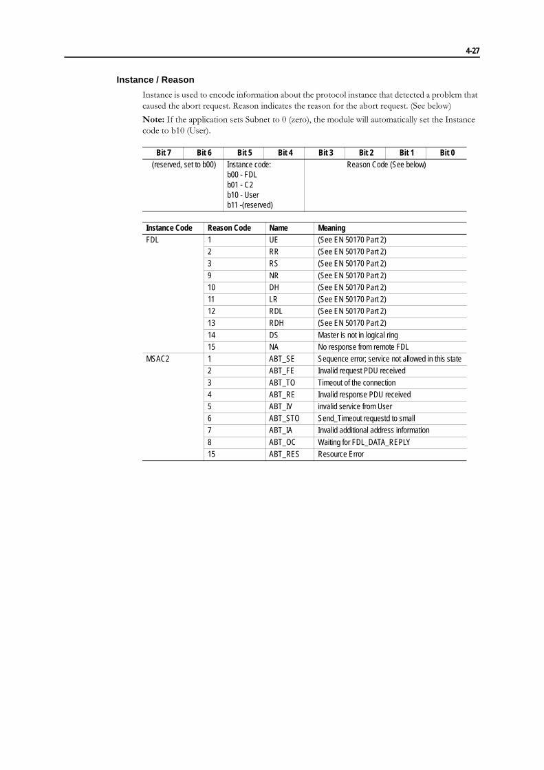
Instance / Reason
Instance is used to encode information about the protocol instance that detected a problem that caused the abort request. Reason indicates the reason for the abort request. (See below)
Note: If the application sets Subnet to 0 (zero), the module will automatically set the Instance code to b10 (User).
Bit 7 Bit 6 Bit 5 Bit 4 Bit 3 Bit 2 Bit 1 Bit 0(reserved, set to b00) Instance code:
b00 - FDLb01 - C2b10 - Userb11 -(reserved)
Reason Code (See below)
Instance Code Reason Code Name MeaningFDL 1 UE (See EN 50170 Part 2)
2 RR (See EN 50170 Part 2)3 RS (See EN 50170 Part 2)
9 NR (See EN 50170 Part 2)10 DH (See EN 50170 Part 2)11 LR (See EN 50170 Part 2)12 RDL (See EN 50170 Part 2)13 RDH (See EN 50170 Part 2)
14 DS Master is not in logical ring15 NA No response from remote FDL
MSAC2 1 ABT_SE Sequence error; service not allowed in this state2 ABT_FE Invalid request PDU received
3 ABT_TO Timeout of the connection4 ABT_RE Invalid response PDU received5 ABT_IV invalid service from User6 ABT_STO Send_Timeout requestd to small7 ABT_IA Invalid additional address information
8 ABT_OC Waiting for FDL_DATA_REPLY15 ABT_RES Resource Error

4-28
FB_APPL_ACYCLIC_ABORT
Description
Command and response layout:
Subnet
This parameter is used to encode information about the location of the source of the abort ini-tiator.
Possible values:
0 - No
1 - Subnet - Local
2 - Subnet - Remote
3 to 255 - (reserved)
Parameter DescriptionCommand initiator ApplicationCommand Name FB_APPL_ACYCLIC_ABORTMessage type 02hCommand number 0011h
Fragmented NoExtended Header data Command: SAP-number of the aborted connection
Response: Fault informationMessage data Command: Subnet, Instance, and Reason for the abortion
Response: The command message data is returnedResponse message If the telegram is not accepted the reason for the rejection is indicated in the
message information word
Command Expected responseMessage ID (ID) (ID)
Message information 4002h 0002hCommand 0011h 0011h FB_APPL_ACYCLIC_ABORT
Data size 0002h 0002h 2 databytes (1 word)Frame count 0001h 0001h
Frame number 0001h 0001hOffset high 0000h 0000hOffset low 0000h 0000h
Extended word 1 - -
Extended word 2 - -Extended word 3 - -Extended word 4 - -Extended word 5 - -Extended word 6 - -
Extended word 7 - -Extended word 8 SAP-number (low byte) ErrorCode 1, ErrorCode 2 DPV1 specific fault information
Message databyte 1 Subnet Subnet Response dataMessage databyte 2 Instance / Reason Instance / Reason

4-29
Instance / Reason
Instance is used to encode information about the protocol instance that detected a problem that caused the abort request. Reason indicates the reason for the abort request. (See below)
Note: If the application sets Subnet to 0 (zero), the module will automatically set the Instance code to b10 (User).
Bit 7 Bit 6 Bit 5 Bit 4 Bit 3 Bit 2 Bit 1 Bit 0(reserved, set to b00) Instance code:
b00 - FDLb01 - C2b10 - Userb11 -(reserved)
Reason Code (See below)
Instance Code Reason Code Name MeaningFDL 1 UE (See EN 50170 Part 2)
2 RR (See EN 50170 Part 2)3 RS (See EN 50170 Part 2)
9 NR (See EN 50170 Part 2)10 DH (See EN 50170 Part 2)11 LR (See EN 50170 Part 2)12 RDL (See EN 50170 Part 2)13 RDH (See EN 50170 Part 2)
14 DS Master is not in logical ring15 NA No response from remote FDL
MSAC2 1 ABT_SE Sequence error; service not allowed in this state2 ABT_FE Invalid request PDU received
3 ABT_TO Timeout of the connection4 ABT_RE Invalid response PDU received5 ABT_IV invalid service from User6 ABT_STO Send_Timeout requestd to small7 ABT_IA Invalid additional address information
8 ABT_OC Waiting for FDL_DATA_REPLY15 ABT_RES Resource Error
4-30
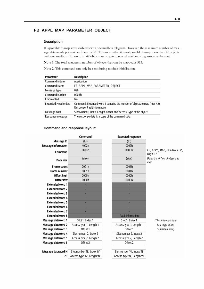
FB_APPL_MAP_PARAMETER_OBJECT
Description
It is possible to map several objects with one mailbox telegram. However, the maximum number of mes-sage data words per mailbox frame is 128. This means that it is not possible to map more than 42 objects with one mailbox. If more than 42 objects are required, several mailbox telegrams must be sent.
Note 1: The total maximum number of objects that can be mapped is 512.
Note 2: This command can only be sent during module initialisation.
Command and response layout:
Parameter DescriptionCommand initiator ApplicationCommand Name FB_APPL_MAP_PARAMETER_OBJECTMessage type 02h
Command number 000BhFragmented NoExtended Header data Command: Extended word 1 contains the number of objects to map (max 42)
Response: Fault informationMessage data Slot Number, Index, Length, Offset and Access Type of the object.
Response message The response data is a copy of the command data.
Command Expected responseMessage ID (ID) (ID)
Message information 4002h 0002h
Command000Bh 000Bh FB_APPL_MAP_PARAMETER_
OBJECT
Data size(size) (size) Datasize, 6 * no of objects to
mapFrame count 0001h 0001h
Frame number 0001h 0001hOffset high 0000h 0000hOffset low 0000h 0000h
Extended word 1 - -Extended word 2 - -Extended word 3 - -Extended word 4 - -
Extended word 5 - -Extended word 6 - -Extended word 7 - -Extended word 8 - Fault information
Message dataword 1 Slot 1, Index 1 Slot 1, Index 1 (The response dataMessage dataword 2 Access type 1, Length 1 Access type 1, Length 1 is a copy of theMessage dataword 3 Offset 1 Offset 1 command data)Message dataword 4 Slot number 2, Index 2 Slot number 2, Index 2Message dataword 5 Access type 2, Length 2 Access type 2, Length 2
Message dataword 6 Offset 2 Offset 2... ... ...
Message dataword N Slot number ‘N’, Index ‘N’ Slot number ‘N’, Index ‘N’-”- Access type ‘N’, Length ‘N’ Access type ‘N’, Length ‘N’

4-31
-”- Offset ‘N’’ Offset ‘N’’

Chapter 5
Fieldbus Specific Area
Memory Map
Global Command
Actual Baurate
User Parameter Data available
0: No User Parameter data available for the application
1: User Parameter data available for the application
Configuration Data available
0: No Configuration data available for the application
1: Configuration data available for the application
Address Memory Area Description0 - 32 Fieldbus Specific IN area Not Used
33 Fieldbus Specific OUT area Global Command
34 Fieldbus Specific OUT area Actual Baudrate35 Fieldbus Specific OUT area User Parameter data available36 Fieldbus Specific OUT area Configuration data available
bit Description0 Reserved1 Set: CLEAR command received2 Set: UnFreeze command received3 Set: Freeze command received
4 Set: Unsync command received5 Set: Sync command received6-7 Reserved
Value Description00h No Baudrate set01h 12 Mbit
02h 6 Mbit03h 3 Mbit04h 1.5 MBit05h 500 kBit
06h 187.5 kBit07h 93.75 kBit08h 45.45 kBit09h 19.2 kBit
0Ah 9.6 kBit

Appendix A
Environmental Specification
Temperature
Operating
+5 to +70 degrees Celsius
Test performed according to IEC-68-2-1 and IEC 68-2-2.
Non Operating
-25 to +85 degrees Celsius
Test performed according to IEC-68-2-1 and IEC 68-2-2.
Relative Humidity
The product is designed for a relative humidity of 5 to 95% non-condensing.
Test performed according to IEC 68-2-30.
EMC compliance
Emission
According to EN 50 081-2:1993
Tested per 55011:1990, class A, radiated
Immunity
According to EN 61000-6-2:1999
Tested per EN 61000-4-2:1995
EN 61000-4-3:1996
EN 61000-4-4:1995
EN 61000-4-5:1995
EN 61000-4-6:1996

Appendix B
Connectors
The module supports the different types of connectors;9-pin Dsub, screw terminal, and 2mm board-to-board. The 9-pin D--sub is the standard connector and is recommended for data transfer rates higher than 1500kbit/s..
9-pin D-sub
Screw Terminal
2mm Board to Board
*) RTS is used in some equipment to determine the direction of transmission. In normal applications only A-Line, B-Line and Shield are used.
**) +5V BUS and GND BUS are used for bus termination. Some devices, like optical transceivers (RS485 to fibre optics) might require external power supply from these pins.
Pin SignalHousing Shield1 NC
2 NC3 B-Line4 RTS*5 GND BUS**6 +5V BUS**
7 NC8 A-Line9 NC
Pin Signal1 +5V BUS**2 GND BUS**3 A-Line4 B-Line
5 Shield6 RTS*
Pin Signal1 Shield2 GND BUS**3 RTS*4 NC
5 A-Line6 B-Line7 NC8 +5V BUS**9 NC
10 NC
5 1
69
Female
10
1

Appendix C
Electrical Characteristics
Supply Voltage
Both the module electronics and the fieldbus interface requires a regulated 5V DC powersupply. For more information regarding power requirements, consult the AnyBus-S Design Guide.
Maximum Current Consumption
The maximum current consumption is 300mA on the bus interface, 300 mA on the electronics interface. The total current consumption for both power ports is 400mA.
PE Grounding
A PE-connection is included on one of the front mounting holes according to the AnyBus-S standard.

Appendix D
Mechanical Specification
Measurements, PCB
The PCB is designed to fulfil the AnyBus-S requirements.
86,0
54,0
2,54
2,54
2,0
2,0
2,0
0,8
0,8
0,9
3x 3,2
0
6,2
12,9
14,3
5,8
37,3
0
2,0
71
,8
1,0
0,75
A A
1,6
0
7,0
55
,5
4,0
A-A

Mechanical Specification D-2
Measurements, Connectors & Switches
Straight Switches & Connectors
16,0
9,7
12,6
25,0
14,1
9,6
12,0
7,613,6
9,75,1
4,6
3,2
2,9
0
12,0
31,0
45,0
53,4
75,6
6,0
11,912,2
5,5 4,7
8,0 8,110,2
9,26,430,9 7,6
7,7
6,4-12,2mm

Mechanical Specification D-3
Angled Switches & Connectors
15,9
22,1
14,2
15,8
16,2
19,510,9
9,7
15,813,7
8,1
8,5
0
12,0
31,0
45,0
53,4
75,6
30,8 6,5
12,6
7,9
9,2
9,75,1
4,6
9,7
5,9
2,8
6,3
25,0
8,4 2,9
3,2
6,4-12,2mm