doc6_c
DESCRIPTION
directional o/c rem543TRANSCRIPT

1MRS100035 (Low)1MRS100036 (High)1MRS100037 (Inst)Issued: 10/1998Version: C
Data subject to change without notice
RE_5_ _Three-Phase DirectionalOvercurrent Protection
Low-Set Stage (DOC6Low)High-Set Stage (DOC6High)
Instantaneous Stage (DOC6Inst)
Contents
1. Introduction .............................................................................................. 3
1.1 Features.............................................................................................. 3
1.2 Application........................................................................................... 3
1.3 Input description.................................................................................. 5
1.4 Output description ............................................................................... 6
2. Description of Operation.......................................................................... 7
2.1 Configuration....................................................................................... 7
2.2 Measuring mode ................................................................................. 7
2.3 Operation criteria................................................................................. 8
2.3.1 Current direction......................................................................... 8
2.3.2 Memory function....................................................................... 12
2.3.3 Non-directional operation of DOC6High and DOC6Inst............ 12
2.3.4 DIRECTION output .................................................................. 13
2.4 Delayed reset facility and drop-off time in DT mode .......................... 13
2.5 IDMT type operation of DOC6Low .................................................... 14
2.5.1 Standard curve groups............................................................. 14
2.5.2 RI curve groups........................................................................ 16
2.5.3 RD curve groups ...................................................................... 16
2.6 Setting groups ................................................................................... 17
2.7 Test mode ......................................................................................... 17
2.8 START, TRIP and CBFP outputs ...................................................... 17
2.9 Resetting........................................................................................... 18
3. Parameters and Events .......................................................................... 19
3.1 General ............................................................................................. 19
3.2 Setting values.................................................................................... 20
3.2.1 Actual settings.......................................................................... 20
3.2.2 Setting group 1......................................................................... 21
3.2.3 Setting group 2......................................................................... 22
3.2.4 Control settings ........................................................................ 23

RE_5_ _ DOC6Low, DOC6High, DOC6Inst ABB Automation
2
3.3 Measurement values .........................................................................25
3.3.1 Input data .................................................................................25
3.3.2 Output data...............................................................................26
3.3.3 Recorded data ..........................................................................26
3.3.4 Events ......................................................................................32
4. Technical Data.........................................................................................34

ABB Automation DOC6Low, DOC6High, DOC6Inst RE_5_ _
3
1.� Introduction
1.1� Features
• Directional single-phase, two-phase or three-phase overcurrent protection
• Definite-time (DT) operation
• DOC6Low: Six inverse-time (IDMT) characteristics
• Current measurement with conventional current transformers or Rogowski coils
• Possibility to use either phase-to-phase voltages or phase-to-earth voltages
• Voltage measurement with conventional voltage transformers or voltage dividers
• DOC6High and DOC6Inst: Non-directional operation in an inrush situation wherea circuit breaker is closed against a close fault and the voltage does not rise to ameasurable level
• Memory function for maintaining the stability and reliability of the directionaloperation at close faults characterized by an extremely low voltage
• Operation on short circuits only or on both earth faults and short circuits
• Two alternative measuring principles: the average value of consecutiveinstantaneous peak-to-peak values or the numerically calculated fundamentalfrequency component of the short-circuit current
• Delayed trip output for the circuit-breaker failure protection (CBFP) function
1.2� Application
This document specifies the functions of the directional overcurrent function blocksDOC6Low, DOC6High and DOC6Inst used in products based on the RED 500Platform. The operation of the low-set stage differs from that of the high-set andinstantaneous stages regarding the following two features:
• the non-directional operation is only included in the high-set and instantaneousstages
• the IDMT type of operation is only inluded in the low-set stage
The directional overcurrent function blocks are designed for directional single-phase,two-phase and three-phase overcurrent and short-circuit protection whenever the DTcharacteristic or, as concerns DOC6Low, the IDMT (Inverse Definite MinimumTime) characteristic is appropriate. Suppression of harmonics is possible.

RE_5_ _ DOC6Low, DOC6High, DOC6Inst ABB Automation
4
3I>
CBFP
3I>>
CBFP
3I>>>
CBFP
)LJXUH��� 3URWHFWLRQ�GLDJUDP�V\PEROV�RI�'2&�/RZ��'2&�+LJK�DQG�'2&�,QVW�)RU�,(&�V\PEROV�XVHG�LQ�VLQJOH�OLQH�GLDJUDPV��UHIHU�WR�WKH�PDQXDO³7HFKQLFDO�'HVFULSWLRQV�RI�)XQFWLRQV��,QWURGXFWLRQ´���056�������080�
)LJXUH��� )XQFWLRQ�EORFN�V\PEROV�RI�'2&�/RZ��'2&�+LJK�DQG�'2&�,QVW

ABB Automation DOC6Low, DOC6High, DOC6Inst RE_5_ _
5
1.3� Input description
Name Type DescriptionIL1 Analogue signal (SINT) Input for measuring phase current IL1
IL2 Analogue signal (SINT) Input for measuring phase current IL2
IL3 Analogue signal (SINT) Input for measuring phase current IL3
U12 Analogue signal (SINT) Input for measuring phase-to-phasevoltage U12 or phase-to-earth voltage U1
U23 Analogue signal (SINT) Input for measuring phase-to-phasevoltage U23 or phase-to-earth voltage U2
U31 Analogue signal (SINT) Input for measuring phase-to-phasevoltage U31 or phase-to-earth voltage U3
BS1 Digital signal (BOOL, active high) Blocking signal 1
BS2 Digital signal (BOOL, active high) Blocking signal 2
TRIGG Digital signal (BOOL, active high) Control signal for triggering theregisters
GROUP Digital signal (BOOL, active high) Control input for switching betweenthe setting groups 1 and 2. WhenGROUP is FALSE, group 1 is active.When GROUP is TRUE, group 2 isactive.
DOUBLE Digital signal (BOOL, active high) Input signal used for doubling the setstart current value temporarily atmagnetizing inrush or start-up
BSREG Digital signal (BOOL, active high) Input for blocking the recording function
RESET Reset signal (BOOL, pos. edge) Input signal for resetting the trip signaland registers of DOC6Low, DOC6Highor DOC6Inst

RE_5_ _ DOC6Low, DOC6High, DOC6Inst ABB Automation
6
1.4� Output description
DOC6Low
Name Type DescriptionDIRECTION Digital signal (BOOL, active high) Current direction information
START Digital signal (BOOL, active high) Start signal
TRIP Digital signal (BOOL, active high) Trip signal
CBFP Digital signal (BOOL, active high) Delayed trip signal for circuit-breaker failure protection (CBFP)
STATUS_IL1 Digital signal (BOOL, active high) Status of IL1
STATUS_IL2 Digital signal (BOOL, active high) Status of IL2
STATUS_IL3 Digital signal (BOOL, active high) Status of IL3
ERR Digital signal (BOOL, active high) Signal for indicating aconfiguration error
DOC6High and DOC6Inst
Name Type DescriptionDIRECTION Digital signal (BOOL, active high) Current direction information
BSOUT Digital signal (BOOL, active high) Blocking signal for blocking-based busbar protection
START Digital signal (BOOL, active high) Start signal
TRIP Digital signal (BOOL, active high) Trip signal
CBFP Digital signal (BOOL, active high) Delayed trip signal for circuit-breaker failure protection (CBFP)
STATUS_IL1 Digital signal (BOOL, active high) Status of IL1
STATUS_IL2 Digital signal (BOOL, active high) Status of IL2
STATUS_IL3 Digital signal (BOOL, active high) Status of IL3
ERR Digital signal (BOOL, active high) Signal for indicating aconfiguration error

ABB Automation DOC6Low, DOC6High, DOC6Inst RE_5_ _
7
2.� Description of Operation
2.1� Configuration
Phase currents can be measured with conventional current transformers or Rogowskicoils. The measuring devices and signal types for analogue channels are selected andconfigured in a special dialogue box of the Relay Configuration Tool included in theCAP 505 Tool Box. Digital inputs are configured in the same programmingenvironment (the number of selectable analogue inputs, digital inputs and digitaloutputs depends on the hardware variant used).
When the analogue channels and digital inputs have been selected and configured inthe dialogue box, the inputs and outputs of the function block can be configured on agraphic worksheet of the configuration tool. The phase currents IL1, IL2 and IL3 areconnected to the IL1, IL2 and IL3 inputs and the phase-to-phase voltages U12, U23 andU31 correspondingly to the U12, U23 and U31 inputs of the function block. If phase-to-earth voltages are used, they are connected to the inputs as follows: U1 to inputU12, U2 to input U23 and U3 to input U31. Furthermore, digital inputs are connectedto the boolean inputs of the function block, and in the same way, the outputs of thefunction block are connected to the output signals.
2.2� Measuring mode
The function block operates on two alternative measuring principles: the averagevalue of consecutive instantaneous peak-to-peak values or the numerically calculatedfundamental frequency component of the short-circuit current. The measuring mode isselected via either an MMI parameter or a serial communication parameter as follows:
Measuring mode Voltage types connected Current measuring principle= Mode 1 Phase-to-phase voltages Peak-to-peak
= Mode 2 Phase-to-phase voltages Fundamental frequency
= Mode 3 Phase-to-earth voltages Peak-to-peak
= Mode 4 Phase-to-earth voltages Fundamental frequency
Voltages are always measured using the numerically calculated fundamentalfrequency component. When phase-to-earth voltages are connected, the phase-to-phase voltages are numerically derived from phase-to-earth voltages within thefunction block.
With both the measuring principles, the operation is insensitive to the DC componentand the operation accuracy is defined in the frequency range f/fn=0.95...1.05. In peak-to-peak measurement, the harmonics of the phase currents are not suppressed,whereas in fundamental frequency measurement the harmonics suppression is about-50 dB at f = n x fn, where n = 2, 3, 4, 5,...

RE_5_ _ DOC6Low, DOC6High, DOC6Inst ABB Automation
8
2.3� Operation criteria
The function block starts if the current flows in the set operating direction andexceeds the set start current in two or more phases or, if earth-fault protection isenabled, in one or more phases. The set start current is automatically doubled whenthe signal connected to the DOUBLE input becomes active. The automatic doublingfunction can be used e.g. during a magnetizing inrush or at start-up.
)LJXUH��� )XQFWLRQ�RI�WKH�'28%/(�LQSXW
When the function block starts, the START signal is set to TRUE. Should thedirectional overcurrent situation exceed the set definite operate time or, at the inverse-time operation, the time determined by the level of the measured current, the functionblock operates. The delay of the heavy-duty output relay is included in the totaloperate time. When the function block operates, the TRIP signal is set to TRUE.
The DT or IDMT timer is allowed to run only if the blocking signal BS1 is not active,i.e. its value is FALSE. When the signal becomes active, i.e. its value turns to TRUE,the timer will be stopped (frozen).
When the blocking signal BS2 is active, the TRIP signal cannot be activated. TheTRIP signal can be blocked by activating the signal BS2 until the function blockdrops off.
2.3.1� Current direction
The operating direction can be set to either “forward” or “reverse” via the settingparameter “Oper. Direction”. The default configuration direction is “forward”, i.e. thepower flow direction is away from the busbar, when the voltage and currenttransformer connections are as drawn in the figure below. The function block willoperate on fault currents flowing in the set direction only.
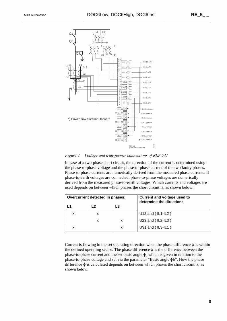
ABB Automation DOC6Low, DOC6High, DOC6Inst RE_5_ _
9
1A5A
1A0,2A
100V
100V
100V
100V
1A5A
1A5A
1A5A
X1.1
161514131211
87
654321
10 9
1918
2221
27
2524
X2.1
X2.2
X2.3
X2.4
X2.5
X2.6
X2.7
X2.8DIFF
DIFF
DIFF
DIFF
DIFF
DIFF
DIFF
DIFF
REF 541(1MRS 090115-AAB/CAB)
Ch 2, CT1
Ch 3, CT2
Ch 4, CT3
Ch 5, CT4
Ch 6, CT5
Ch 7, VT1
Ch 8, VT2
Ch 9, VT3
Ch 10, VT4
S1
S2
S1
S2
P1
P2
L3L1
L3L1A
N
n
ada dn
Q1
Q9
Q0
*)
Ch 9, sensor
Ch 10, sensor
Ch 8, sensor
Ch 7, sensor
Ch 4, sensor
Ch 3, sensor
Ch 2, sensor
Ch 1, sensor
curr
dir
*) Power flow direction: forward
)LJXUH��� 9ROWDJH�DQG�WUDQVIRUPHU�FRQQHFWLRQV�RI�5()����
In case of a two-phase short circuit, the direction of the current is determined usingthe phase-to-phase voltage and the phase-to-phase current of the two faulty phases.Phase-to-phase currents are numerically derived from the measured phase currents. Ifphase-to-earth voltages are connected, phase-to-phase voltages are numericallyderived from the measured phase-to-earth voltages. Which currents and voltages areused depends on between which phases the short circuit is, as shown below:
Overcurrent detected in phases: Current and voltage used todetermine the direction:
L1 L2 L3
x x U12 and ( IL1-IL2 )
x x U23 and ( IL2-IL3 )
x x U31 and ( IL3-IL1 )
Current is flowing in the set operating direction when the phase difference ϕ is withinthe defined operating sector. The phase difference ϕ is the difference between thephase-to-phase current and the set basic angle ϕb which is given in relation to thephase-to-phase voltage and set via the parameter “Basic angle ϕb”. How the phasedifference ϕ is calculated depends on between which phases the short circuit is, asshown below:

RE_5_ _ DOC6Low, DOC6High, DOC6Inst ABB Automation
10
Overcurrent detected in phases: Phase difference used to determinethe direction:
L1 L2 L3
x x ϕ12 = ϕ(U12) + ϕb - ϕ(IL1-IL2)
x x ϕ23 = ϕ(U23) + ϕb - ϕ(IL2-IL3)
x x ϕ31 = ϕ(U31) + ϕb - ϕ(IL3-IL1)
x x x ϕ12, ϕ23 and ϕ31
In case of a three-phase short circuit i.e. when an overcurrent is detected in all threephases, the function block will operate if at least one of the phase differences ϕ12, ϕ23
and ϕ31 is within the operating sector.
The operating sector for forward operation is within +/ -80° from the basic angle ϕband the one for reverse operation correspondingly the sector outside +/ -100° from ϕb,as shown in Figure 5. The operating sector includes a hysteresis of 10°, which meansthat when the operating direction is set to forward and the phase difference ϕ is withinthe operating sector of +/-80°, the sector will be enlarged to +/-90°. When ϕ is outsidethe operating sector, the size of the sector will remain as +/-80°. Correspondingly, theoperating sector for reverse operation is enlarged to the sector outside +/-90° whenthe phase difference ϕ is within the operating sector.
)LJXUH��� 'HWHUPLQDWLRQ�RI�FXUUHQW�GLUHFWLRQ�LQ�D�WZR�SKDVH�VKRUW�FLUFXLW�VLWXDWLRQ
Figure 5 shows an example of a short circuit between the phases L1 and L2. Here thefault current is flowing in forward direction since the phase difference ϕ12 is +30°,which is within the forward direction operating sector.
The use of earth-fault protection is optional, which means that when the settingparameter “Earth fault pr.” is given the value “Disabled”, the function block operateson short circuits only, and when the parameter is set to “Enabled”, the function blockoperates on both short circuits and earth faults.

ABB Automation DOC6Low, DOC6High, DOC6Inst RE_5_ _
11
The principle for determining the current direction in case of an earth fault dependson whether phase-to-phase voltages or phase-to-earth voltages are connected to thefunction block. When phase-to-earth voltages are connected, the direction of thecurrent is determined using the phase-to-earth voltage and the phase current of thefaulty phase. Which phase difference is used depends on in which phase the earthfault is, as shown below:
Overcurrent detected in phase: Phase difference used to determinethe direction:
L1 L2 L3
x ϕ1 = ϕ(U1) + ϕb - ϕ(IL1)
x ϕ2 = ϕ(U2) + ϕb - ϕ(IL2)
x ϕ3 = ϕ(U3) + ϕb - ϕ(IL3)
The operating sector is defined in relation to the basic angle ϕb, which is given inrelation to the phase-to-earth voltage. As for the short circuit case the operating sectorfor forward operation is within +/-80° from the basic angle ϕb and the one for reverseoperation the sector outside +/-100° from ϕb, both with the hysteresis of 10°.
)LJXUH��� 'HWHUPLQDWLRQ�RI�FXUUHQW�GLUHFWLRQ�LQ�FDVH�RI�DQ�HDUWK�IDXOW�ZKHQ�SKDVH�WR�HDUWK�YROWDJHV�DUH�PHDVXUHG
Figure 6 shows an example of an earth fault in phase L1. Here the phase difference ϕ1is +30°, which means that the current is flowing in forward direction.
When phase-to-phase voltages are connected to the function block, the currentdirection in an earth-fault situation is determined using the same phase differences asin a short circuit situation. Which phase difference is used depends on in which phasethe earth fault is, as shown below:

RE_5_ _ DOC6Low, DOC6High, DOC6Inst ABB Automation
12
Overcurrent detected in phase: Phase difference used to determinethe direction:
L1 L2 L3
x ϕ12 = ϕ(U12) + ϕb - ϕ(IL1-IL2)
x ϕ23 = ϕ(U23) + ϕb - ϕ(IL2-IL3)
x ϕ31 = ϕ(U31) + ϕb - ϕ(IL3-IL1)
The operation sectors in this case are the same as in the short circuit case.
2.3.2� Memory function
The function block is provided with a memory function to secure a reliable andcorrect directional relay operation in case of a close short circuit or an earth faultcharacterized by an extremely low voltage. At sudden loss of voltage, the phase angleof the voltage is calculated on the basis of a fictive voltage. The fictive voltage iscalculated using the voltage measured before the fault occured, assuming that thevoltage is not affected by the fault. The memory function enables the function blockto operate up to 2 seconds after a total loss of voltage.
When the voltage falls below 0.07 x Un at a close fault, the fictive voltage will beused to determine the phase angle. The measured voltage is applied again as soon asthe voltage rises above 0.08 x Un. The fictive voltage is also discarded if the measuredvoltage stays below 0.08 x Un for more than 2 seconds or if the fault currentdisappears while the fictive voltage is in use.
When the voltage is below 0.08 x Un and the fictive voltage either cannot be usedbecause the phase angle could not be reliably measured before the fault situation orhas already been used for 2 seconds, the current direction cannot be determined andthe function block will not operate.
2.3.3� Non-directional operation of DOC6High and DOC6Inst
The high-set or instantaneous stage can be set to operate non-directionally insituations where the current direction cannot be determined, i.e. when the voltage isbelow 0.08 x Un and the fictive voltage cannot be used. This feature is enabled whenthe setting parameter “Nondir. operat.” is set to “Enabled”. When the parameter isgiven the value “Disabled”, the function block will operate non-directionally only inan inrush situation as described below.
The function block will always operate non-directionally in an inrush situation wherea circuit breaker is closed against a close fault and the current direction cannot bereliably measured, i.e. voltage does not rise above 0.08 x Un. The state of the settingparameter “Nondir. operat.” does not affect this feature.
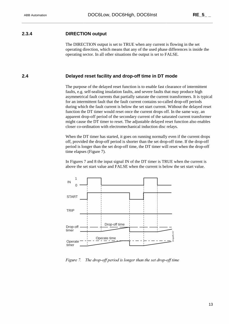
ABB Automation DOC6Low, DOC6High, DOC6Inst RE_5_ _
13
2.3.4� DIRECTION output
The DIRECTION output is set to TRUE when any current is flowing in the setoperating direction, which means that any of the used phase differences is inside theoperating sector. In all other situations the output is set to FALSE.
2.4� Delayed reset facility and drop-off time in DT mode
The purpose of the delayed reset function is to enable fast clearance of intermittentfaults, e.g. self-sealing insulation faults, and severe faults that may produce highasymmetrical fault currents that partially saturate the current transformers. It is typicalfor an intermittent fault that the fault current contains so-called drop-off periodsduring which the fault current is below the set start current. Without the delayed resetfunction the DT timer would reset once the current drops off. In the same way, anapparent drop-off period of the secondary current of the saturated current transformermight cause the DT timer to reset. The adjustable delayed reset function also enablescloser co-ordination with electromechanical induction disc relays.
When the DT timer has started, it goes on running normally even if the current dropsoff, provided the drop-off period is shorter than the set drop-off time. If the drop-offperiod is longer than the set drop-off time, the DT timer will reset when the drop-offtime elapses (Figure 7).
In Figures 7 and 8 the input signal IN of the DT timer is TRUE when the current isabove the set start value and FALSE when the current is below the set start value.
Operate time
Drop-off time
IN
START
TRIP
0
1
Drop-offtimer
Operatetimer
Dro
poff1
.fh7
)LJXUH��� 7KH�GURS�RII�SHULRG�LV�ORQJHU�WKDQ�WKH�VHW�GURS�RII�WLPH

RE_5_ _ DOC6Low, DOC6High, DOC6Inst ABB Automation
14
If the drop-off period is shorter than the set drop-off time and the DT timer time haselapsed during the drop-off period, the function block will trip once the currentexceeds the set start value again (Figure 8).
Operate time
Drop-off time
IN
START
TRIP
0
1
Drop-offtimer
Operatetimer D
ropo
ff2.fh
7
)LJXUH��� 7KH�GURS�RII�SHULRG�LV�VKRUWHU�WKDQ�WKH�VHW�GURS�RII�WLPH
2.5� IDMT type operation of DOC6Low
At the inverse-time mode of the low-set stage the operate time of the function block isa function of the current; the higher the current, the shorter is the operate time. Sixtime/current curve groups are available. Four of the groups comply with the BS 142and IEC 60255 standards, whereas the two curve groups RI and RD (RXIDG) arespecial type of curve groups corresponding to the ABB praxis. The desired operatetime characteristic is selected via the parameter “Operation mode”.
The shortest operate time at the inverse-time operation is limited by a specialadjustable minimum time. The definite minimum time will not allow operate timesshorter than the set minimum time, which is why the inverse-time mode is called theIDMT mode (Inverse Definite Minimum Time).
2.5.1� Standard curve groups
The four internationally standardized inverse-time characteristics incorporated in theinverse-time operation of the function are:
• normal inverse (NI)
• very inverse (VI)
• extremely inverse (EI)
• long-time inverse (LI)
(For a graphical presentation of the curves, refer to the manual “TechnicalDescriptions of Functions, Introduction”.)

ABB Automation DOC6Low, DOC6High, DOC6Inst RE_5_ _
15
The relationship between time and current is in accordance with the standard IEC60255 and can be expressed as follows
t[s]k x
I
I( ) 1
=
>−
βα
where
• t = operate time in seconds
• k = adjustable time multiplier
• I = phase current
• I> = adjustable start current
The values of the constants a and b determine the slope as follows
Inverse-timecharacteristic
α β
Normal inverse 0.02 0.14
Very inverse 1.0 13.5
Extremely inverse 2.0 80.0
Long-time inverse 1.0 120
According to the standard BS 142: 1966 the effective current range is defined as2...20 times the set start current. If the time/current characteristic is normal inverse,very inverse, or extremely inverse, the function has to start at the latest when thecurrent exceeds the set start current 1.3 times. For the long-time inverse characteristicthe effective current range is specified to be 2...7 times the set start current and therelay is to start at the latest when the current exceeds the setting value 1.1 times. Thethree-phase directional overcurrent function block DOC6Low will start and the IDMTintegration will begin once the current exceeds the set start value and the phase anglecriteria is fulfilled.
The operate time tolerances specified by the standard BS 142 : 1966 are the following(E denotes the accuracy in per cent):
I/I > Normal Very Extremely Long time2 2.22E 2.34E 2.44E 2.34E
5 1.13E 1.26E 1.48E 1.26E
7 - - - 1.00E
10 1.01E 1.01E 1.02E -
20 1.00E 1.00E 1.00E -

RE_5_ _ DOC6Low, DOC6High, DOC6Inst ABB Automation
16
The tolerance factors have to be smaller than those defined by the standard BS 142:1966 for currents of 2 and 5 times the setting. The function block DOC6Lowcomplies with the tolerances of class 5 (E = 5.0%) for all inverse-time curves.
For example:
I/I>= 10, characteristic = Normal
Operate time tolerance = 1.01 x 5.0% = 5.05%
2.5.2� RI curve groups
The RI-type inverse-time characteristic is a special characteristic mainly used toobtain time grading with mechanical relays. The characteristic can be expressed asfollows:
t sk
0.339 0.236 x I
I
=−
>
2.5.3� RD curve groups
The RD-type characteristic is a special characteristic mainly used in earth-faultprotection where a high degree of selectivity is required also at high-resistance faults.Mathematically, the characteristic can be expressed as follows:
t[s] = 5.8 -1.35 x lnI
k x I >
The accuracy of the RI- and RD-type characteristics is 5%. Also with the RI- and RD-type characteristics, the function block will start and the IDMT integration will beginonce the current exceeds the set start current.

ABB Automation DOC6Low, DOC6High, DOC6Inst RE_5_ _
17
2.6� Setting groups
Two different groups of setting values, group 1 and group 2, are available for thefunction block. Switching between the two groups can be done in the following threeways:
1 Locally via the control parameter “Group selection”1) of the MMI
2 Over the communication bus by writing the parameter V31)
3 By means of the input signal GROUP when allowed via the parameter “Groupselection” (i.e. when V3 = 21)).1) Group selection (V3): 0 = Group 1; 1 = Group 2; 2 = GROUP input
The control parameter “Active group” indicates the setting group valid at a giventime.
2.7� Test mode
The digital outputs of the function block can be activated with separate controlparameters for each output either locally via the MMI or externally via the serialcommunication. When an output is activated with the test parameter, an eventindicating the test is generated.
The protection functions operate normally while the outputs are tested.
2.8� START, TRIP and CBFP outputs
The output signal START is always pulse-shaped. The minimum pulse width of thecorresponding output signal is set via a separate parameter on the MMI or via serialcommunication. If the start situation is longer than the set pulse width, the STARTsignal remains active until the start situation is over. The output signal TRIP mayhave a non-latching or latching feature. When the latching mode has been selected,the TRIP signal remains active until the output is reset even if the operation criteriahave reset.
The outputs STATUS_IL1, STATUS_IL2 and STATUS_IL3 indicate the presentstatus of each phase. The outputs remain active as long as the start situation of thecorresponding phase is on. Latching feature is not available.
The function block provides a delayed trip signal CBFP after the TRIP signal unlessthe fault has disappeared during the set CBFP time delay. In circuit-breaker failureprotection, the CBFP output can be used to operate a circuit breaker in front of thecircuit breaker of the feeder. The control parameter “Trip pulse” also sets the width ofthe CBFP output signal.

RE_5_ _ DOC6Low, DOC6High, DOC6Inst ABB Automation
18
2.9� Resetting
The TRIP output signal and the registers can be reset either via the RESET input, orover the serial bus or the local MMI.
The operation indicators, latched trip signal and recorded data can be reset as follows:
Operationindicators
Latched tripsignal
Recordeddata
RESET input of the function block 1) X X
Parameter F035V013 for DOC6Low 1) X X
Parameter F036V013 for DOC6High 1) X X
Parameter F037V013 for DOC6Inst 1) X X
General parameter F001V011 2) X
General parameter F001V012 2) X X
General parameter F001V013 2) X X X
Push-button C 2) X
Push-buttons C + E (2 s) 2) X X
Push-buttons C + E (5 s) 2) X X X1) Resets the latched trip signal and recorded data of the particular function block2) Affects all function blocks

ABB Automation DOC6Low, DOC6High, DOC6Inst RE_5_ _
19
3.� Parameters and Events
3.1� General
• Each function block has a specific channel number for serial communicationparameters and events. The channel for DOC6Low is 35, that for DOC6High 36and that for DOC6Inst 37.
• The data direction of the parameters defines the use of each parameter as follows:
Data direction DescriptionR, R/M Read only
W Write only
R/W Read and write
• The different event mask parameters (see section “Control settings”) affect thevisibility of events on the MMI or on serial communication (LON or SPA) asfollows:
Event mask 1 (FxxxV101/102) SPA / MMI (LON)
Event mask 2 (FxxxV103/104) LON
Event mask 3 (FxxxV105/106) LON
Event mask 4 (FxxxV107/108) LON
For example, if only the events E3, E4 and E5 are to be seen on the MMI of therelay terminal, the event mask value 56 (8 + 16 + 32) is written to the “Event mask1” parameter (FxxxV101).
In case a function block includes more than 32 events, there are two parametersinstead of e.g. the “Event mask 1” parameter: the parameter “Event mask 1A”(FxxxV101) covers the events 0...31 and “Event mask 1B”(FxxxV102) the events32...63.

RE_5_ _ DOC6Low, DOC6High, DOC6Inst ABB Automation
20
3.2� Setting values
3.2.1� Actual settings
DOC6Low
Parameter Code Values Unit Default Data
direction
Explanation
Operation mode S1 0 ... 7 1) - 1 R Selection of operation mode and
inverse-time characteristic at
IDMT mode
Start current S2 0.05...40.00 x In 0.05 R Start current
Operate time S3 0.05...300.00 s 0.05 R Operate time at DT mode
Time multiplier S4 0.05...1.00 - 0.05 R Time multiplier at IDMT mode
Basic angle ϕb S5 0...90 ° 60 R Basic angle ϕb for directional
operation
Oper. direction S6 0 or 1 2) - 0 R Selection of forward/ reverse
operation
Earth fault pr. S7 0 or 1 3) - 0 R Earth fault protection
1) Operation mode 0 = Not in use; 1 = Definite time; 2 = Extremely inv.; 3 = Very inv.;4 = Normal inv.; 5 = Long-time inv.; 6 = RI-type inv.; 7 = RD-type inv.
2) Oper. direction 0 = Forward; 1 = Reverse3) Earth fault pr. 0 = Disabled; 1 = Enabled
DOC6High and DOC6Inst
Parameter Code Values Unit Default Data
direction
Explanation
Operation mode S1 0 ... 2 1) - 1 R Selection of operation mode
Start current S2 0.05...40.00 x In 0.05 R Start current
Operate time S3 0.05...300.00 s 0.05 R Operate time at DT mode
Basic angle ϕb S4 0...90 ° 60 R Basic angle ϕb for
directional operation
Oper. direction S5 0 or 1 2) - 0 R Selection of forward/ reverse
operation
Earth fault pr. S6 0 or 1 3) - 0 R Earth-fault protection
Nondir. operat. S7 0 or 1 3) - 0 R Non-directional operation
when the direction cannot
be determined
1) Operation mode 0 = Not in use; 1 = Definite time; 2 = Instantaneous2) Oper. direction 0 = Forward; 1 = Reverse3) Earth fault pr./ Nondir. operat. 0 = Disabled; 1 = Enabled
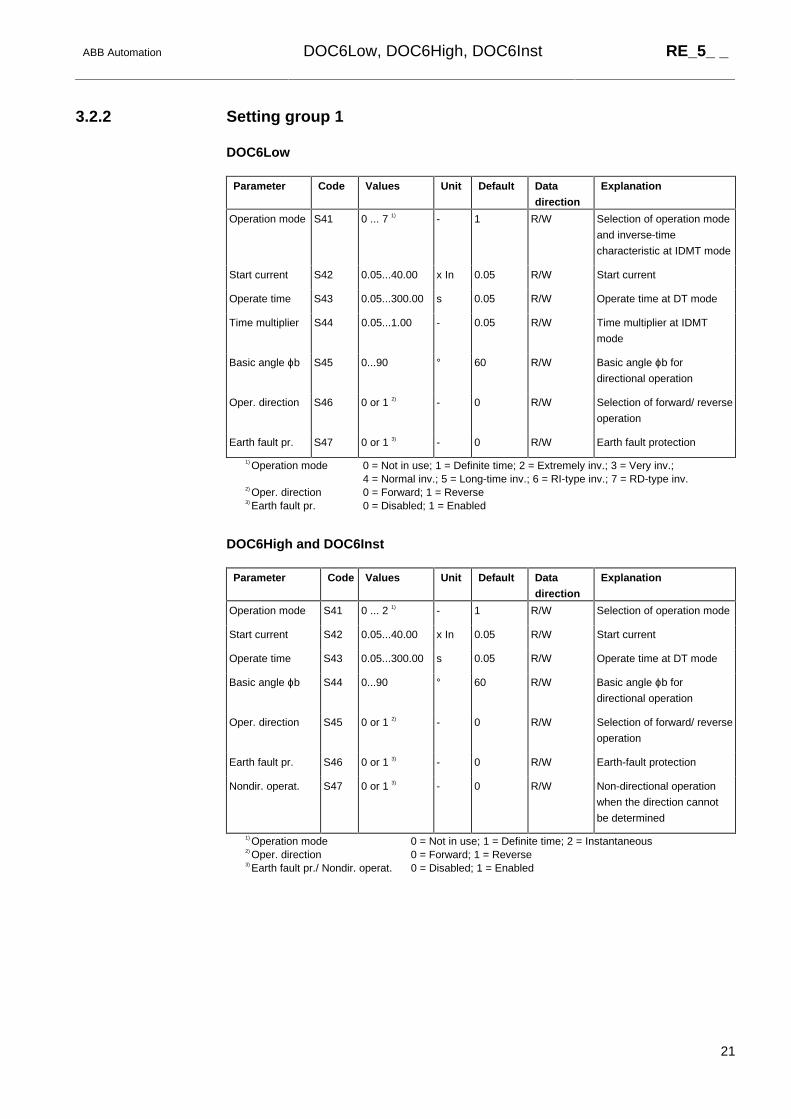
ABB Automation DOC6Low, DOC6High, DOC6Inst RE_5_ _
21
3.2.2� Setting group 1
DOC6Low
Parameter Code Values Unit Default Data
direction
Explanation
Operation mode S41 0 ... 7 1) - 1 R/W Selection of operation mode
and inverse-time
characteristic at IDMT mode
Start current S42 0.05...40.00 x In 0.05 R/W Start current
Operate time S43 0.05...300.00 s 0.05 R/W Operate time at DT mode
Time multiplier S44 0.05...1.00 - 0.05 R/W Time multiplier at IDMT
mode
Basic angle ϕb S45 0...90 ° 60 R/W Basic angle ϕb for
directional operation
Oper. direction S46 0 or 1 2) - 0 R/W Selection of forward/ reverse
operation
Earth fault pr. S47 0 or 1 3) - 0 R/W Earth fault protection
1) Operation mode 0 = Not in use; 1 = Definite time; 2 = Extremely inv.; 3 = Very inv.;4 = Normal inv.; 5 = Long-time inv.; 6 = RI-type inv.; 7 = RD-type inv.
2) Oper. direction 0 = Forward; 1 = Reverse3) Earth fault pr. 0 = Disabled; 1 = Enabled
DOC6High and DOC6Inst
Parameter Code Values Unit Default Data
direction
Explanation
Operation mode S41 0 ... 2 1) - 1 R/W Selection of operation mode
Start current S42 0.05...40.00 x In 0.05 R/W Start current
Operate time S43 0.05...300.00 s 0.05 R/W Operate time at DT mode
Basic angle ϕb S44 0...90 ° 60 R/W Basic angle ϕb for
directional operation
Oper. direction S45 0 or 1 2) - 0 R/W Selection of forward/ reverse
operation
Earth fault pr. S46 0 or 1 3) - 0 R/W Earth-fault protection
Nondir. operat. S47 0 or 1 3) - 0 R/W Non-directional operation
when the direction cannot
be determined
1) Operation mode 0 = Not in use; 1 = Definite time; 2 = Instantaneous2) Oper. direction 0 = Forward; 1 = Reverse3) Earth fault pr./ Nondir. operat. 0 = Disabled; 1 = Enabled

RE_5_ _ DOC6Low, DOC6High, DOC6Inst ABB Automation
22
3.2.3� Setting group 2
DOC6Low
Parameter Code Values Unit Default Data
direction
Explanation
Operation mode S71 0 ... 7 1) - 1 R/W Selection of operation mode
and inverse-time characteristic
at IDMT mode
Start current S72 0.05...40.00 x In 0.05 R/W Start current
Operate time S73 0.05...300.00 s 0.05 R/W Operate time at DT mode
Time multiplier S74 0.05...1.00 - 0.05 R/W Time multiplier at IDMT mode
Basic angle ϕb S75 0...90 ° 60 R/W Basic angle ϕb for directional
operation
Oper. direction S76 0 or 1 2) - 0 R/W Selection of forward/ reverse
operation
Earth fault pr. S77 0 or 1 3) - 0 R/W Earth fault protection
1) Operation mode 0 = Not in use; 1 = Definite time; 2 = Extremely inv.; 3 = Very inv.; 4 = Normalinv.; 5 = Long-time inv.; 6 = RI-type inv.; 7 = RD-type inv.
2) Oper. direction 0 = Forward; 1 = Reverse3) Earth fault pr. 0 = Disabled; 1 = Enabled
DOC6High and DOC6Inst
Parameter Code Values Unit Default Data
direction
Explanation
Operation mode S71 0 ... 2 1) - 1 R/W Selection of operation mode
Start current S72 0.05...40.00 x In 0.05 R/W Start current
Operate time S73 0.05...300.00 s 0.05 R/W Operate time at DT mode
Basic angle ϕb S74 0...90 ° 60 R/W Basic angle ϕb for directional
operation
Oper. direction S75 0 or 1 2) - 0 R/W Selection of forward/ reverse
operation
Earth fault pr. S76 0 or 1 3) - 0 R/W Earth-fault protection
Nondir. operat. S77 0 or 1 3) - 0 R/W Non-directional operation
when the direction cannot be
determined
1) Operation mode 0 = Not in use; 1 = Definite time; 2 = Instantaneous2) Oper. direction 0 = Forward; 1 = Reverse3) Earth fault pr./ Nondir. operat. 0 = Disabled; 1 = Enabled

ABB Automation DOC6Low, DOC6High, DOC6Inst RE_5_ _
23
3.2.4� Control settings
DOC6Low
Parameter Code Values Unit Default Data
direction
Explanation
Measuring mode V1 0...3 1) - 0 R/W Selection of measuring mode
Drop-off time V2 0...1000 ms 0 R/W Resetting time of the operate
time counter at DT mode
Group selection V3 0 ... 2 2) - 0 R/W Selection of the active setting
group
Active group V4 0 or 1 3) - 0 R/M Active setting group
Start pulse V5 0...1000 ms 0 R/W Minimum pulse width of START
signal
Trip signal V6 0 or 1 4) - 0 R/W Selection of latching feature for
TRIP output
Trip pulse V7 40...1000 ms 40 R/W Minimum pulse width of TRIP
and CBFP
Minimum time V8 0.03...10.00 s 0.03 R/W Minimum operate time at IDMT
mode
CBFP time V9 100...1000 ms 100 R/W Operate time of the delayed trip
CBFP
Reset registers V13 1=Reset - 0 W Resetting of latched trip signal
and registers
Test START V31 0 or 1 5) - - R/W Testing of START
Test TRIP V32 0 or 1 5) - - R/W Testing of TRIP
Test CBFP V33 0 or 1 5) - - R/W Testing of CBFP
Event mask 1 V101 0...16383 - 63 R/W Event mask 1 for event
transmission (E0 ... E13)
Event mask 2 V103 0...16383 - 63 R/W Event mask 2 for event
transmission (E0 ...E13)
Event mask 3 V105 0...16383 - 63 R/W Event mask 3 for event
transmission (E0 ... E13)
Event mask 4 V107 0...16383 - 63 R/W Event mask 4 for event
transmission (E0 ... E13)
1) Measuring mode 0 = Mode 1; 1 = Mode 2; 2 = Mode 3; 3 = Mode 42) Group selection 0 = Group 1; 1 = Group 2; 2 = GROUP input3) Active group 0 = Group 1; 1 = Group 24) Trip signal 0 = Non-latching; 1 = Latching5) Test 0 = Do not activate; 1 = Activate

RE_5_ _ DOC6Low, DOC6High, DOC6Inst ABB Automation
24
DOC6High and DOC6Inst
Parameter Code Values Unit Default Data
direction
Explanation
Measuring mode V1 0...3 1) - 0 R/W Selection of measuring mode
Drop-off time V2 0...1000 ms 0 R/W Resetting time of the operate
time counter at DT mode
Group selection V3 0 ... 2 2) - 0 R/W Selection of the active setting
group
Active group V4 0 or 1 3) - 0 R/M Active setting group
Start pulse V5 0...1000 ms 0 R/W Minimum pulse width of START
signal
Trip signal V6 0 or 1 4) - 0 R/W Selection of latching feature for
TRIP output
Trip pulse V7 40...1000 ms 40 R/W Minimum pulse width of TRIP
and CBFP
CBFP time V8 100...1000 ms 100 R/W Operate time of the delayed trip
CBFP
Reset registers V13 1=Reset - 0 W Resetting of latched trip signal
and registers
Test START V31 0 or 1 5) - - R/W Testing of START
Test TRIP V32 0 or 1 5) - - R/W Testing of TRIP
Test CBFP V33 0 or 1 5) - - R/W Testing of CBFP
Event mask 1 V101 0...65535 - 63 R/W Event mask 1 for event
transmission (E0 ... E15)
Event mask 2 V103 0...65535 - 63 R/W Event mask 2 for event
transmission (E0 ...E15)
Event mask 3 V105 0...65535 - 63 R/W Event mask 3 for event
transmission (E0 ... E15)
Event mask 4 V107 0...65535 - 63 R/W Event mask 4 for event
transmission (E0 ... E15)
1) Measuring mode 0 = Mode 1; 1 = Mode 2; 2 = Mode 3; 3 = Mode 42) Group selection 0 = Group 1; 1 = Group 2; 2 = GROUP input3) Active group 0 = Group 1; 1 = Group 24) Trip signal 0 = Non-latching; 1 = Latching5) Test 0 = Do not activate; 1 = Activate

ABB Automation DOC6Low, DOC6High, DOC6Inst RE_5_ _
25
3.3� Measurement values
3.3.1� Input data
Parameter Code Values Unit Default Data
direction
Explanation
Current IL1 I1 0.00...60.00 x In 0.00 R/M Phase current IL1
Current IL2 I2 0.00...60.00 x In 0.00 R/M Phase current IL2
Current IL3 I3 0.00...60.00 x In 0.00 R/M Phase current IL3
Voltage U12 I4 0.00...2.00 x Un 0.00 R/M Phase-to-phase voltage U12
Voltage U23 I5 0.00...2.00 x Un 0.00 R/M Phase-to-phase voltage U23
Voltage U31 I6 0.00...2.00 x Un 0.00 R/M Phase-to-phase voltage U31
Voltage U1 I7 0.00...2.00 x Un 0.00 R/M Phase-to-earth voltage U1
Voltage U2 I8 0.00...2.00 x Un 0.00 R/M Phase-to-earth voltage U2
Voltage U3 I9 0.00...2.00 x Un 0.00 R/M Phase-to-earth voltage U3
Phase angle ϕ 12 I10 -180...+180 ° 0 R/M Phase difference ϕb - ϕ(phase-to-
phase current)
Phase angle ϕ 23 I11 -180...+180 ° 0 R/M Phase difference ϕb - ϕ(phase-to-
phase current)
Phase angle ϕ 31 I12 -180...+180 ° 0 R/M Phase difference ϕb - ϕ(phase-to-
phase current)
Phase angle ϕ 1 I13 -180...+180 ° 0 R/M Phase difference ϕb - ϕ(phase
current)
Phase angle ϕ 2 I14 -180...+180 ° 0 R/M Phase difference ϕb - ϕ(phase
current)
Phase angle ϕ 3 I15 -180...+180 ° 0 R/M Phase difference ϕb - ϕ(phase
current)
Input BS1 I16 0 or 1 1) - 0 R/M Block signal BS1
Input BS2 I17 0 or 1 1) - 0 R/M Block signal BS2
Input TRIGG I18 0 or 1 1) - 0 R/M Signal for triggering the registers
Input GROUP I19 0 or 1 2) - 0 R/M Signal for switching between the
groups 1 and 2
Input DOUBLE I20 0 or 1 1) - 0 R/M Signal for doubling the set start
current
Input BSREG I21 0 or 1 1) - 0 R/M Signal for blocking the recording
function
Input RESET I22 0 or 1 1) - 0 R/M Signal for resetting the output
signals and registers of
DOC6Low, DOC6High or
DOC6Inst
1) Input_ 0 = Not active; 1 = Active2) Input GROUP 0 = Group 1; 1 = Group 2
RE_5_ _ DOC6Low, DOC6High, DOC6Inst ABB Automation
26
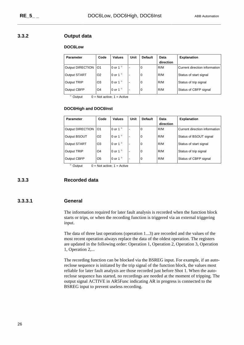
3.3.2� Output data
DOC6Low
Parameter Code Values Unit Default Data
direction
Explanation
Output DIRECTION O1 0 or 1 1) - 0 R/M Current direction information
Output START O2 0 or 1 1) - 0 R/M Status of start signal
Output TRIP O3 0 or 1 1) - 0 R/M Status of trip signal
Output CBFP O4 0 or 1 1) - 0 R/M Status of CBFP signal
1) Output 0 = Not active; 1 = Active
DOC6High and DOC6Inst
Parameter Code Values Unit Default Data
direction
Explanation
Output DIRECTION O1 0 or 1 1) - 0 R/M Current direction information
Output BSOUT O2 0 or 1 1) - 0 R/M Status of BSOUT signal
Output START O3 0 or 1 1) - 0 R/M Status of start signal
Output TRIP O4 0 or 1 1) - 0 R/M Status of trip signal
Output CBFP O5 0 or 1 1) - 0 R/M Status of CBFP signal
1) Output 0 = Not active; 1 = Active
3.3.3� Recorded data
3.3.3.1� General
The information required for later fault analysis is recorded when the function blockstarts or trips, or when the recording function is triggered via an external triggeringinput.
The data of three last operations (operation 1...3) are recorded and the values of themost recent operation always replace the data of the oldest operation. The registersare updated in the following order: Operation 1, Operation 2, Operation 3, Operation1, Operation 2,...
The recording function can be blocked via the BSREG input. For example, if an auto-reclose sequence is initiated by the trip signal of the function block, the values mostreliable for later fault analysis are those recorded just before Shot 1. When the auto-reclose sequence has started, no recordings are needed at the moment of tripping. Theoutput signal ACTIVE in AR5Func indicating AR in progress is connected to theBSREG input to prevent useless recording.

ABB Automation DOC6Low, DOC6High, DOC6Inst RE_5_ _
27
3.3.3.2� Date and time
The time stamp indicates the rising edge of the START, TRIP or TRIGG signal.
3.3.3.3� Duration
At the DT mode of operation the duration of the start situation is recorded as apercentage of the set operate time and at the IDMT mode of operation as a percentageof the calculated operate time.
3.3.3.4� Currents, voltages and phase angles
If the function block trips, the measured current, voltage and phase difference valuesare updated at the moment of tripping i.e. on the rising edge of the TRIP signal. Forexternal triggering, the measured values are updated at the moment of triggering i.e.on the rising edge of the input signal TRIGG. If the function block starts but does nottrip, the values captured one fundamental cycle (20 ms at rated frequency 50 Hz) afterthe beginning of the start situation are recorded. Thus the values of the currents,voltages and phase differences always originate from the same moment.
The currents are recorded as multiples of the rated current In and the voltages asmultiples of the rated voltage Un. The phase differences are recorded in degrees.
3.3.3.5� Current direction for DOC6Low
The state of the DIRECTION signal of DOC6Low is recorded at the same moment ascurrents and voltages are recorded.
3.3.3.6� Non-directional operation of DOC6High and DOC6Inst
If the function block DOC6High or DOC6Inst is operating non-directionally at themoment of recording, the recorded parameter "Nondir. operat." has the value"Active".
3.3.3.7� Status data
The status data of the input signals BS1, BS2 and DOUBLE (Active or Not active) aswell as the “Active group” parameter are recorded at the moment of triggering.

RE_5_ _ DOC6Low, DOC6High, DOC6Inst ABB Automation
28
3.3.3.8� Priority
The priority of the recording function is the following:
1 Tripping
2 Starting
3 External triggering,
which means that if the function block has started, it will neglect an externaltriggering request.

ABB Automation DOC6Low, DOC6High, DOC6Inst RE_5_ _
29
3.3.3.9� Recorded data 1
Parameter Code Values Unit Default Data
direction
Explanation
Date V201 YYYY-MM-DD - - R/M Recording date
Time V202 hh:mm:ss.mss - - R/M Recording time
Duration V203 0.0...100.0 % 0.0 R/M Duration of start situation
IL1 mean V204 0.00...60.00 x In 0.00 R/M Filtered value of IL1
IL2 mean V205 0.00...60.00 x In 0.00 R/M Filtered value of IL2
IL3 mean V206 0.00...60.00 x In 0.00 R/M Filtered value of IL3
IL1 peak V207 0.00...60.00 x In 0.00 R/M Momentary peak of IL1
IL2 peak V208 0.00...60.00 x In 0.00 R/M Momentary peak of IL2
IL3 peak V209 0.00...60.00 x In 0.00 R/M Momentary peak of IL3
Voltage U12 V210 0.00...2.00 x Un 0.00 R/M Filtered value of U12
Voltage U23 V211 0.00...2.00 x Un 0.00 R/M Filtered value of U23
Voltage U31 V212 0.00...2.00 x Un 0.00 R/M Filtered value of U31
Voltage U1 V213 0.00...2.00 x Un 0.00 R/M Filtered value of U1
Voltage U2 V214 0.00...2.00 x Un 0.00 R/M Filtered value of U2
Voltage U3 V215 0.00...2.00 x Un 0.00 R/M Filtered value of U3
Phase angle ϕ12 V216 -180...+180 ° 0.00 R/M Phase difference ϕb -
ϕ(phase-to-phase current)
Phase angle ϕ23 V217 -180...+180 ° 0.00 R/M Phase difference ϕb -
ϕ(phase-to-phase current)
Phase angle ϕ31 V218 -180...+180 ° 0.00 R/M Phase difference ϕb -
ϕ(phase-to-phase current)
Phase angle ϕ1 V219 -180...+180 ° 0.00 R/M Phase difference ϕb - ϕ(phase
current)
Phase angle ϕ2 V220 -180...+180 ° 0.00 R/M Phase difference ϕb - ϕ(phase
current)
Phase angle ϕ3 V221 -180...+180 ° 0.00 R/M Phase difference ϕb - ϕ(phase
current)
DIRECTION V222 0 or 1 1) - 0 R/M Status of DIRECTION output
(DOC6Low)
Nondir. operat. V222 0 or 1 1) - 0 R/M Status of non-directional
operation (DOC6High & -Inst)
BS1 V223 0 or 1 1) - 0 R/M Status of BS1 input
BS2 V224 0 or 1 1) - 0 R/M Status of BS2 input
DOUBLE V225 0 or 1 1) - 0 R/M Status of DOUBLE input
Active group V226 0 or 1 2) - 0 R/M Active setting group
1) Status 0: = Not active; 1 = Active2) Active group 0 = Group 1; 1 = Group 2

RE_5_ _ DOC6Low, DOC6High, DOC6Inst ABB Automation
30
3.3.3.10� Recorded data 2
Parameter Code Values Unit Default Data
direction
Explanation
Date V301 YYYY-MM-DD - - R/M Recording date
Time V302 hh:mm:ss.mss - - R/M Recording time
Duration V303 0.0...100.0 % 0.0 R/M Duration of start situation
IL1 mean V304 0.00...60.00 x In 0.00 R/M Filtered value of IL1
IL2 mean V305 0.00...60.00 x In 0.00 R/M Filtered value of IL2
IL3 mean V306 0.00...60.00 x In 0.00 R/M Filtered value of IL3
IL1 peak V307 0.00...60.00 x In 0.00 R/M Momentary peak of IL1
IL2 peak V308 0.00...60.00 x In 0.00 R/M Momentary peak of IL2
IL3 peak V309 0.00...60.00 x In 0.00 R/M Momentary peak of IL3
Voltage U12 V310 0.00...2.00 x Un 0.00 R/M Filtered value of U12
Voltage U23 V311 0.00...2.00 x Un 0.00 R/M Filtered value of U23
Voltage U31 V312 0.00...2.00 x Un 0.00 R/M Filtered value of U31
Voltage U1 V313 0.00...2.00 x Un 0.00 R/M Filtered value of U1
Voltage U2 V314 0.00...2.00 x Un 0.00 R/M Filtered value of U2
Voltage U3 V315 0.00...2.00 x Un 0.00 R/M Filtered value of U3
Phase angle ϕ12 V316 -180...+180 ° 0.00 R/M Phase difference ϕb -
ϕ(phase-to-phase current)
Phase angle ϕ23 V317 -180...+180 ° 0.00 R/M Phase difference ϕb -
ϕ(phase-to-phase current)
Phase angle ϕ31 V318 -180...+180 ° 0.00 R/M Phase difference ϕb -
ϕ(phase-to-phase current)
Phase angle ϕ1 V319 -180...+180 ° 0.00 R/M Phase difference ϕb - ϕ(phase
current)
Phase angle ϕ2 V320 -180...+180 ° 0.00 R/M Phase difference ϕb - ϕ(phase
current)
Phase angle ϕ3 V321 -180...+180 ° 0.00 R/M Phase difference ϕb - ϕ(phase
current)
DIRECTION V322 0 or 1 1) - 0 R/M Status of DIRECTION output
(DOC6Low)
Nondir. operat. V322 0 or 1 1) - 0 R/M Status of non-directional
operation (DOC6High & -Inst)
BS1 V323 0 or 1 1) - 0 R/M Status of BS1 input
BS2 V324 0 or 1 1) - 0 R/M Status of BS2 input
DOUBLE V325 0 or 1 1) - 0 R/M Status of DOUBLE input
Active group V326 0 or 1 2) - 0 R/M Active setting group
1) Status 0: = Not active; 1 = Active2) Active group 0 = Group 1; 1 = Group 2

ABB Automation DOC6Low, DOC6High, DOC6Inst RE_5_ _
31
3.3.3.11� Recorded data 3
Parameter Code Values Unit Default Data
direction
Explanation
Date V401 YYYY-MM-DD - - R/M Recording date
Time V402 hh:mm:ss.mss - - R/M Recording time
Duration V403 0.0...100.0 % 0.0 R/M Duration of start situation
IL1 mean V404 0.00...60.00 x In 0.00 R/M Filtered value of IL1
IL2 mean V405 0.00...60.00 x In 0.00 R/M Filtered value of IL2
IL3 mean V406 0.00...60.00 x In 0.00 R/M Filtered value of IL3
IL1 peak V407 0.00...60.00 x In 0.00 R/M Momentary peak of IL1
IL2 peak V408 0.00...60.00 x In 0.00 R/M Momentary peak of IL2
IL3 peak V409 0.00...60.00 x In 0.00 R/M Momentary peak of IL3
Voltage U12 V410 0.00...2.00 x Un 0.00 R/M Filtered value of U12
Voltage U23 V411 0.00...2.00 x Un 0.00 R/M Filtered value of U23
Voltage U31 V412 0.00...2.00 x Un 0.00 R/M Filtered value of U31
Voltage U1 V413 0.00...2.00 x Un 0.00 R/M Filtered value of U1
Voltage U2 V414 0.00...2.00 x Un 0.00 R/M Filtered value of U2
Voltage U3 V415 0.00...2.00 x Un 0.00 R/M Filtered value of U3
Phase angle ϕ12 V416 -180...+180 ° 0.00 R/M Phase difference ϕb - ϕ(phase-
to-phase current)
Phase angle ϕ23 V417 -180...+180 ° 0.00 R/M Phase difference ϕb - ϕ(phase-
to-phase current)
Phase angle ϕ31 V418 -180...+180 ° 0.00 R/M Phase difference ϕb - ϕ(phase-
to-phase current)
Phase angle ϕ1 V419 -180...+180 ° 0.00 R/M Phase difference ϕb - ϕ(phase
current)
Phase angle ϕ2 V420 -180...+180 ° 0.00 R/M Phase difference ϕb - ϕ(phase
current)
Phase angle ϕ3 V421 -180...+180 ° 0.00 R/M Phase difference ϕb - ϕ(phase
current)
DIRECTION V422 0 or 1 1) - 0 R/M Status of DIRECTION output
(DOC6Low)
Nondir. operat. V422 0 or 1 1) - 0 R/M Status of non-directional
operation (DOC6High & -Inst)
BS1 V423 0 or 1 1) - 0 R/M Status of BS1 input
BS2 V424 0 or 1 1) - 0 R/M Status of BS2 input
DOUBLE V425 0 or 1 1) - 0 R/M Status of DOUBLE input
Active group V426 0 or 1 2) - 0 R/M Active setting group
1) Status 0: = Not active; 1 = Active2) Active group 0 = Group 1; 1 = Group 2
RE_5_ _ DOC6Low, DOC6High, DOC6Inst ABB Automation
32
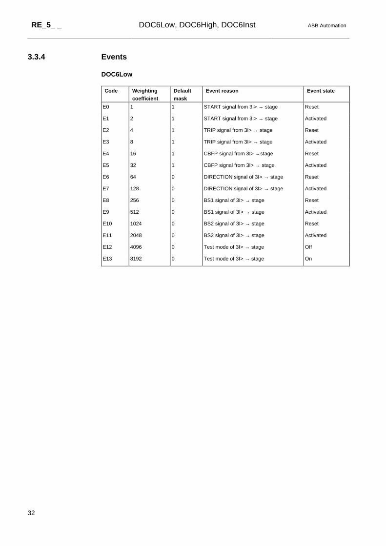
3.3.4� Events
DOC6Low
Code Weighting
coefficient
Default
mask
Event reason Event state
E0 1 1 START signal from 3I> → stage Reset
E1 2 1 START signal from 3I> → stage Activated
E2 4 1 TRIP signal from 3I> → stage Reset
E3 8 1 TRIP signal from 3I> → stage Activated
E4 16 1 CBFP signal from 3I> →stage Reset
E5 32 1 CBFP signal from 3I> → stage Activated
E6 64 0 DIRECTION signal of 3I> → stage Reset
E7 128 0 DIRECTION signal of 3I> → stage Activated
E8 256 0 BS1 signal of 3I> → stage Reset
E9 512 0 BS1 signal of 3I> → stage Activated
E10 1024 0 BS2 signal of 3I> → stage Reset
E11 2048 0 BS2 signal of 3I> → stage Activated
E12 4096 0 Test mode of 3I> → stage Off
E13 8192 0 Test mode of 3I> → stage On

ABB Automation DOC6Low, DOC6High, DOC6Inst RE_5_ _
33
DOC6High and DOC6Inst
Code Weighting
coefficient
Default
mask
Event reason Event state
E0 1 1 START signal from 3I>> → or 3I>>> → stage Reset
E1 2 1 START signal from 3I>> → or 3I>>> → stage Activated
E2 4 1 TRIP signal from 3I>> → or 3I>>> → stage Reset
E3 8 1 TRIP signal from 3I>> → or 3I>>> → stage Activated
E4 16 1 CBFP signal from 3I>> → or 3I>>> → stage Reset
E5 32 1 CBFP signal from 3I>> → or 3I>>> → stage Activated
E6 64 0 BSOUT signal from 3I>> → or 3I>>> → stage Reset
E7 128 0 BSOUT signal from 3I>> → or 3I>>> → stage Activated
E8 256 0 DIRECTION signal of 3I>> → or 3I>>> → stage Reset
E9 512 0 DIRECTION signal of 3I>> → or 3I>>> → stage Activated
E10 1024 0 BS1 signal of 3I>> → or 3I>>> → stage Reset
E11 2048 0 BS1 signal of 3I>> → or 3I>>> → stage Activated
E12 4096 0 BS2 signal of 3I>> → or 3I>>> → stage Reset
E13 8192 0 BS2 signal of 3I>> → or 3I>>> → stage Activated
E14 16384 0 Test mode of 3I>> → or 3I>>> → stage Off
E15 32768 0 Test mode of 3I>> → or 3I>>> → stage On

RE_5_ _ DOC6Low, DOC6High, DOC6Inst ABB Automation
34
4.� Technical Data
Operation accuracies At the frequency range f/fn = 0.95...1.05:
Current measurement:
at currents in the range 0.1...10 x In
± 2.5% of set value or ± 0.01 x In
at currents in the range 10...40 x In
± 5.0% of set value
Voltage measurement:
± 2.5% of measured value or ± 0.01 x Un
Phase angle measurement: ± 2°
Start time Injected currents > 2.0 x start current:
f/fn = 0.95...1.05 internal time < 42 ms
total time1) < 50 ms
Reset time 40...1000 ms (depends on the minimum pulse width set for the
TRIP output)
Reset ratio Typ. 0.95 (range 0.95...0.98)
Retardation time Total retardation time when the current
drops below the start value2) < 45 ms
Operate time accuracy
at definite-time mode
Depends on the frequency of the current measured:
f/fn = 0.95...1.05: ±2% of set value or ± 20 ms2)
Accuracy class index E
at inverse-time mode
Depends on the frequency of the current measured:
(DOC6Low) f/fn = 0.95…1.05: Class index E = 5.0 or ±20 ms2)
Frequency dependence of the
settings and operate times
Measuring mode Suppression of harmonics
(see above) 0 or 2 No suppression
1 or 3 -50 dB at f = n x fn, where n = 2, 3, 4, 5,…
Configuration data Task execution interval (Relay Configuration Tool): 10 ms
at the rated frequency fn = 50 Hz
1) Includes the delay of the signal relay2) Includes the delay of the heavy-duty output relay
Technical revision history
Technical revision Change
D -