do - steer engineering · figure 15: under-cut element geometry unraveled. this element is used to...
TRANSCRIPT

Di
CD
Do


A Technology Update on Twin-screw Extrusion
by
Dr. Babu Padmanabhan Ph.D
GEOMETRY Unraveled
Di
CD
Do
www.drbabupadmanabhan.com

Introduction
Co-rotating Twin-screw extruders are versatile devices that allow work to be done efficiently on plastic
materials. The work done generally raises the temperature of the material being processed, resulting in a
partial or complete fusion of the mixture, an increase in the uniformity of the composition, a chemical
union between the components constituting the mixture and finally a reduction in the size of particles in
that mixture. Work done on the material is the result of application of shear forces, extensional forces that
cause elongation or stretching of material, compressive forces that results in pressure build-up and
squeezing of the material and bending forces that causes fibers and layers to fold and interact. These
forces occur in three dimensional space inside the extruder defined by the Axial Plane, Longitudinal
plane for each screw and several Radial planes. Flow of material between elements in different radial
planes creates lateral shear in the material. In general, radial and lateral shear rates are 10 to 100 times
greater in magnitude compared to axial or longitudinal shear stress.
Radial and Lateral shear are not experienced uniformly by every macro-molecule or particle in the mix
leading to the most common difficulty in plastics processing. Improvements in the working of the
extruder always lead to creating circumstances for uniformity in the radial and lateral shear rates,
extensional flow patterns and frequent re-orientation.
Any effort to fully understand the working of a twin-screw extruder has to begin with a study of the
geometry of the twin-screw equipment. In 1978, Booy [1] conducted such a study based on about 20 years
of work carried out in the field. Since then, important innovations such as Eccentric Elements and
Fractional Lobed Elements have revolutionized the effectiveness of the equipment.
This paper attempts to provide a most recent update on the geometry of the elements, the crucial part of
the processing section in a co-rotating twin-screw extruder.
Technology Update on Twin-screw Extrusion: Geometry Unraveled
-2-
GEOMETRY Unraveled

Known Element Geometry
The essential requirement of a closely intermeshing co-rotating twin-screw extruder element profile is the ability for one screw to wipe the 1other and vice-versa. The Barrel Diameter (D ) and Center-distance (Cd) are the fundamental parameters used to define the geometry of the b
element. The conveying screws, kneading blocks, mixing elements and other elements are formed by the helical or linear transformation of the
cross-sectional geometry of the profile.
_____________________________________
1 Barrels are also referred as Cylinders or Housing
The relationship between the screw profile parameters and the barrel parameters can be written in the following manner
Barrel Diameter (D ) = Outer Diameter (D ) + 2 * Barrel-Screw Clearance (δ )b o b
Center Distance (Cd) = {Outer Diameter (D ) + Minor Diameter (D )}/2 + Screw-Screw Clearance (δ )o i s
The ratio of the Outer Diameter (D ) and the Minor Diameter (D ) is called the Ratio of Diameters (Rd) or the D /D ratio.o i o i
For a ratio of 1.50, it can be seen from this table that it is not possible to design a tri-lobed (three lobes) profile. Presently, most twin-2screw extruders are designed with ratio of 1.50 and above. Therefore, the bi-lobed (two lobes) geometry is the most commonly used.
Figure 1: Cross-section of a Barrel with Element
-3-
¥2.420 <Rd < 1
Ratio ofDiameters (Rd)
Number ofLobes (Nl)
1.000 <Rd <1.180 1,2,3,4
1.180 <Rd <1.366 1,2,3
1.370 <Rd <2.414 1,2
GEOMETRY Unraveled
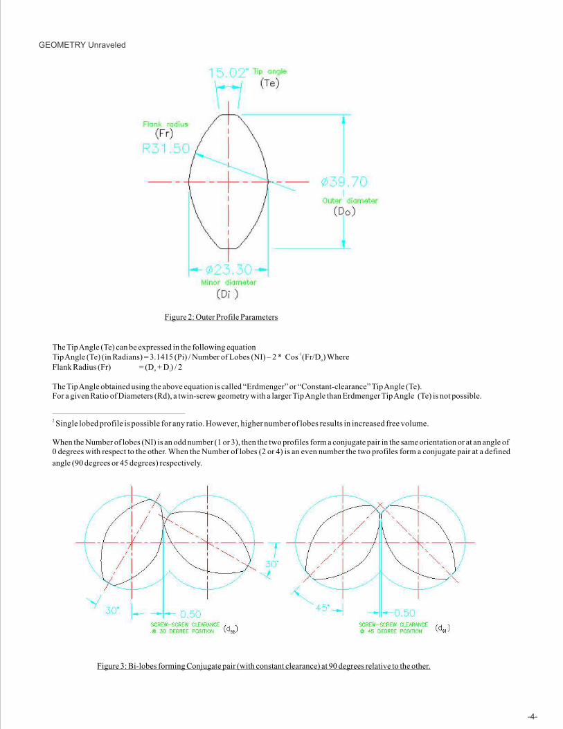
Figure 2: Outer Profile Parameters
The Tip Angle (Te) can be expressed in the following equation-1Tip Angle (Te) (in Radians) = 3.1415 (Pi) / Number of Lobes (NI) – 2 * Cos (Fr/D ) Whereo
Flank Radius (Fr) = (D + D ) / 2o i
The Tip Angle obtained using the above equation is called “Erdmenger” or “Constant-clearance” Tip Angle (Te).For a given Ratio of Diameters (Rd), a twin-screw geometry with a larger Tip Angle than Erdmenger Tip Angle (Te) is not possible.
_____________________________________________________________
2 Single lobed profile is possible for any ratio. However, higher number of lobes results in increased free volume.
When the Number of lobes (NI) is an odd number (1 or 3), then the two profiles form a conjugate pair in the same orientation or at an angle of 0 degrees with respect to the other. When the Number of lobes (2 or 4) is an even number the two profiles form a conjugate pair at a defined
angle (90 degrees or 45 degrees) respectively.
Figure 3: Bi-lobes forming Conjugate pair (with constant clearance) at 90 degrees relative to the other.
-4-
GEOMETRY Unraveled

The clearances play an important role in ensuring that the screw profile can center itself inside the barrel at the time of processing.
Smaller or larger clearances can be used while processing different type of material.
Typical Clearance between the Screw and the Barrel (δ ) = 0.25mm
Typical Clearance between the two Screws (δ ) = 0.5mms
For a constant clearance profile δ = δ = δ ; clearances at all rotational position is constant.s s1 s2
Due to certain processing requirements (or manufacturing convenience), the Actual Tip Angle (Ta) used may be smaller than the
Erdmenger Tip Angle (Te). This modification changes the clearance when the profile rotates to a new position.
Figure 4: Bi-lobes forming Conjugate pair with varying clearances
It is possible to design the geometry using a single arc. Such geometry result in a varying clearance. Interestingly, the highest clearance
although at the 45 degree position is not at the tip but a little below it. This results in a reduction of wear at the tip.
b
-5-
Figure 5: Bi-lobed Single-arc profile forming a Conjugate pair
GEOMETRY Unraveled

Figure 6: Conveying Screw Element
The screw element is obtained by a helical transformation. This transformation is defined by a continuous rotation with a forward movement
(translation) along the axis of rotation. While looking at the screw element such that the rotation is in a clockwise direction, if the translation is
downward then the screw is called a Right Handed Screw element. For a clockwise rotation, if the translation is upward, then the screw is
called a Left Handed Screw element. The Lead of the screw element is defined as the translation length for a complete turn (360 degrees).
The important Conveying screw element parameters are therefore the Lead (Ld), Hand (Hd) and Length (Ln). When very long lead elements
where the lead is 10D or more are used in right and left lead combination, the formation looks similar to a Farrel type continuous mixer
element.
-6-
Figure 7: Kneading Element
GEOMETRY Unraveled

The Kneading Elements are formed by translation of the profile by a distance called the Segment Thickness. The next segment is started at a
new twist angle and taken through another translation. There is usually an overlap between the adjacent segments resulting in a clearance
between the segments.
The important Kneading Element parameters are the Length (Ln), Twist Angle (TwA), Hand (Hd) and Segment Thickness (Sn) and
Clearances (Cn).
Eccentric Element Geometry
In 1989, Häring et al.[3] introduced a new concept in Element Design. They discovered that the profile can be designed for a smaller diameter
ratio (Rd) for a given same center distance and moved eccentric to the shaft. This enables tri-lobed profile to be designed for diameter ratios as
high as 1.5 or more.
Figure 8: 3 Lobed Eccentric elements with Do/Di = 1.
It may be noted that concentric tri-lobed elements cannot be used in a bi-lobed extruder with Do/Di greater than 1.37. Eccentric lobes used as in the form of conveying screws are sometimes referred to as camel-back elements. Otherwise, eccentric lobed elements are used as kneading
blocks. An advantage in using eccentric lobed elements is that it reduces some of the non-uniformity in lateral shear. It all leads to more
frequent reorientation causing improvement in mixing action.
Fractional Lobes
In 1963, Erdmenger [6] wrote in a relatively less known Patent document, “one disadvantage that was hitherto encountered in apparatuses of
this type was that it was only possible to vary the dimensions lying in the axial direction but not the dimension lying transversely to the axis,
e.g. the thickness of the layer of material used, which often has an important effect on the transfer of heat or the transfer of material or the
course of the reaction”. Tri-lobed profile was modified in a new manner in this invention – a predecessor to the Fractional lobed elements.
Erdmenger calls this as the most important alteration in practice. This design is an instance of fractional lobed element but only half of it. It
should be designated under the fractional lobe naming convention as the 1.3.50B/2.
-7-
GEOMETRY Unraveled

Sakagami [4] recognized that Element profile
can be created by applying different Diameter
Ratios from lobe to lobe. In the case of the
example shown below [R#], one of the bi-lobe
has the standard ratio, while the other one has a
decreased ratio resulting in an increased Inner
Diameter (Di) and decreased Outer Diameter
(Do) which is clearly evident in the figure.
Sakagami calls this SMAP screw design and
believes that kneading blocks can be
completely eliminated for melting with this
design. A screw elements formed with this
design resembles a barrier screw in a single
screw extruder.
Figure 9: Erdmenger’s half a Fractional Lobed Element Design
-8-
GEOMETRY Unraveled
Figure 10: Sakagami Modification resulting in a complete fractional lobed element 1.2.66

Fractional Lobe Geometry takes this approach to any number of lobes with a unified concept. Fractional lobes are formed using two different
Integer lobes together. At this time, there is only one condition to be met that the ratio of the two such lobes should also be an integer.
Therefore a Single flight profile (Uni-lobe) and a Bi-lobe can form fractional lobes such as 1.2.xx where xx can be number from 01 to 99.
These numbers 01 to 99 will define whether the fractional lobe will look more like a single flight element or a bi-lobed element. A Single
flight profile and a Four-lobe profile can form fractional lobes such as 1.4.50 etc. 1 and 3 lobes can also be combined as well as 2 and 4 lobed.
These combinations result in an infinite series of profiles to chose from offering enormous capability in the hands of extruder users and
designers.
Figure 11a: Fractional Lobed Geometry 1.4.50 Figure 11b: Fractional Lobed Geometry 1.2.50
Figure 11c: Fractional Lobed Geometry 1.3.80a
-9-
Figure 12: Fractional Lobed Geometry 1.3.80b
GEOMETRY Unraveled
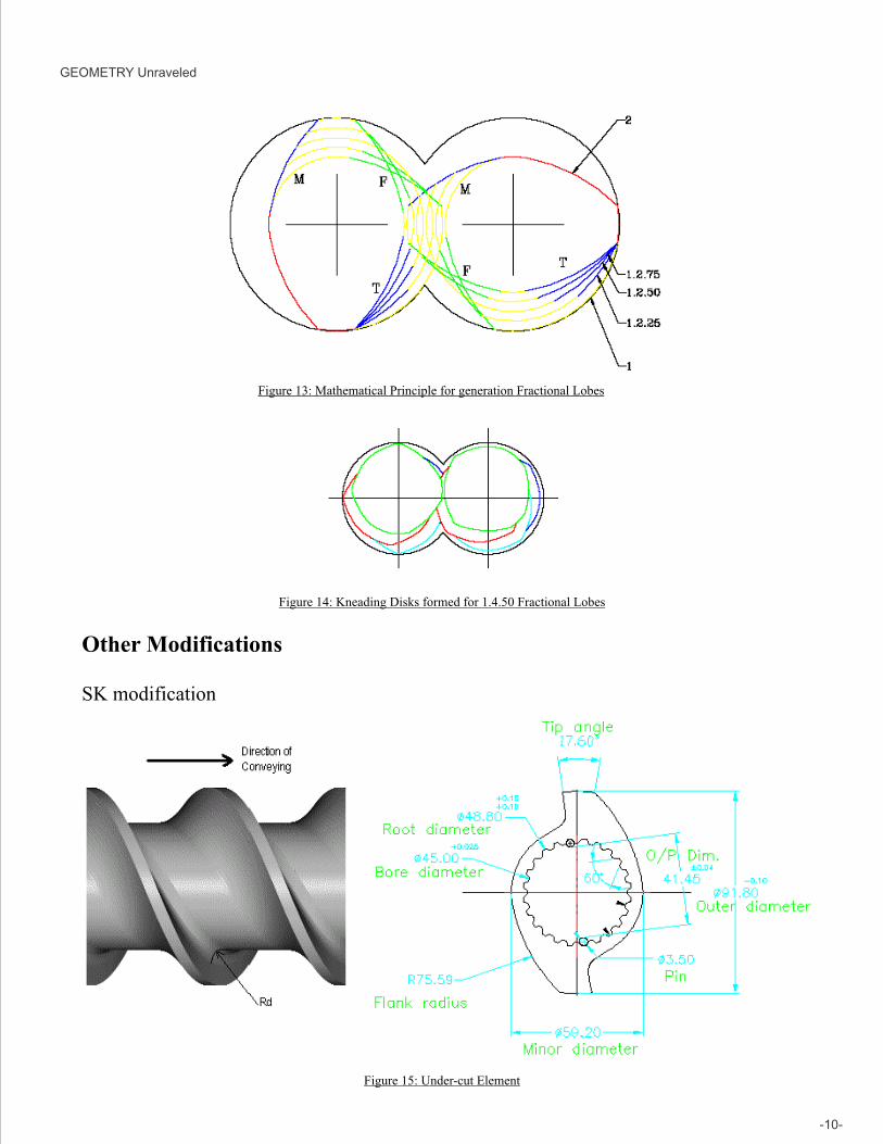
Figure 14: Kneading Disks formed for 1.4.50 Fractional Lobes
Figure 13: Mathematical Principle for generation Fractional Lobes
-10-
Other Modifications
SK modification
Figure 15: Under-cut Element
GEOMETRY Unraveled

This element is used to enhance the free volume during intake or venting. The axial cross-section is modified to become perpendicular to the
axis with a small radius (Rd) at the minor diameter.
It is important to note these elements are only partially wiping and not fully wiping the other element. These elements are generally used in the
intake zone before the solid material forms a melt. However, they can be used in any zone that is partially filled after melting. This is because
the flow of material can itself create the effect of cleaning. Importantly, wiping profiles does not always clean, since cleaning action requires
transfer of material forward during the act. If material is pushed backwards or in a radial direction, cleaning does not Occur.
FV modification (Patent Pending)
These are specially modified highly efficient conveying elements. The elements can convey (by ploughing into the material with a shovel like surface) slippery and other difficult to convey materials at high rates compared to any of the available element geometry.
Figure 16: SFV element for Intake Zone
-11-
Figure 17: TFV element for Side-feed Zone
These elements have the ability to feed low bulk density material (such as a 50% Talc pre-mix) at an extremely high rate (around 2 to 4 times the
capacity of a SK type element in starve feed mode).
These elements are capable of turning a feed-limited extruder (as in the case of applications with low bulk density material) to that of a torque
limited one (as in the case of most applications). The geometry has a special nature of improving the feed-rate at greater speeds unlike standard
elements which tend to fluidize the material and a drop in feed-rate occurs at higher speeds.
Several other modifications including screw mixing elements such as SMEs, ZMEs, TMEs have been left out from this discussion. These
grooved modifications sacrifice on self-cleaning either by wiping or due to natural flow and were a quick-fix remedy rather than a lasting
solution to certain distributive mixing needs. In general, these elements are slowly getting replaced with more scientifically designed elements.
GEOMETRY Unraveled

Summary
Co-rotating twin-screw extruders are versatile mixing devices that can contribute to the
development of new plastic materials. This paper attempts to provide the latest
development in designing the heart of this equipment. Already, a number of fractional
lobe geometry has been used to form various elements. These have resulted in
improving the melting and mixing characteristics of the extruder. Concerted efforts are
being made to carryout further developmental activity to enable the plastics industry to
realize complete benefit from this concept. Ultimately the task of an extruder is to
carryout the right amount of work of the right kind (shearing, stretching, folding or
squeezing) at the right place for the right amount of time. Plastics processing has been a
technology’s domain however still an art form. With newer elements and more detailed
understanding, it would soon enter into a realm of exact science.
-12-
GEOMETRY Unraveled
References
1. M. L. Booy, Polymer Engineering and Science, Sep 1978
2. R. Erdmenger, U.S. Patent 2,670,188 Feb. 23, 1954
3. E. Häring et al U. S. Patent 4,824, 256, Apr 25, 1989
4. M. Sakagami, U. S. Patent 4,300, 839, Nov 17, 1981
5. J. Blach, DE 4239220, May 26, 1994
6. R. Erdmenger, U. S. Patent 3,254,367 Jun 7, 1966
7. Padmanabhan et al, “Effect of Element Geometry…”, ANTEC 2005.
Visitwww.steerworld.com
www.extruderprocessingzone.comwww.extrudertimes.com

USA
STEER AMERICA LLC116 Eva Drive,Gibsonville,NC 27249.
Tel: +1-866-984-1800 Fax: +1-540-540-9144
Email: [email protected]: www.steeramerica.com
EUROPE
Extruder Experts GmbH & Co. KG Am Handwerkerzentrum 1 / Office B27, D - 52156 Monschau-Imgenbroich, Germany.
Tel: +49 -2472-987-98 17 Fax: +49 -2472-987-98 95
Email: [email protected]: www.extruder-experts.com
www.steerworld.comwww.extruderprocessingzone.com
This booklet is brought to you by :
For more information please contact :
INDIA
STEER ENGINEERING Pvt Ltd.,290, 4th Main, 4th Phase,Peenya Industrial Area,Bangalore 560 058, India.
Tel: +91-80-23723309/10Fax: +91-80-23723307
Email: [email protected] [email protected]: www.steerworld.com
JAPAN
STEER JAPAN Fukui Building Room No.402 , 3-21-7 Higashiueno, Taito-ku, Tokyo, 110-000, Japan.
Tel: +81-3-6411-5770 Fax: +81-3-3831-3230
Email: [email protected]: www.steerjapan.com