dnvgl-st-0438 control and protection systems for … transfer of control software from load...
TRANSCRIPT

STANDARD
DNVGL-ST-0438 Edition April 2016
Control and protection systems for wind turbines
DNV GL AS
The electronic pdf version of this document found through http://www.dnvgl.com is the officially binding version. The documents are available free of charge in PDF format.

FOREWORD
DNV GL standards contain requirements, principles and acceptance criteria for objects, personnel,organisations and/or operations.© DNV GL AS April 2016
Any comments may be sent by e-mail to [email protected]
This service document has been prepared based on available knowledge, technology and/or information at the time of issuance of this document. The use of thisdocument by others than DNV GL is at the user's sole risk. DNV GL does not accept any liability or responsibility for loss or damages resulting from any use ofthis document.
C
hang
es –
cur
rent
CHANGES – CURRENTGeneralThis is a new document.
Standard, DNVGL-ST-0438 – Edition April 2016 Page 3
DNV GL AS

C
onte
nts
ContentsCHANGES – CURRENT .................................................................................................. 3
Sec.1 Introduction.................................................................................................. 71.1 Scope .....................................................................................................71.2 General...................................................................................................71.3 Objectives ..............................................................................................71.4 Application .............................................................................................71.5 Certification ...........................................................................................81.6 References .............................................................................................81.7 Definitions..............................................................................................9
1.7.1 Verbal forms .................................................................................91.7.2 Terms ..........................................................................................9
1.8 Acronyms, abbreviations and symbols .................................................101.8.1 Acronyms and abbreviations..........................................................101.8.2 Symbols .....................................................................................11
Sec.2 General design requirements ...................................................................... 122.1 General.................................................................................................122.2 Descriptive approach............................................................................122.3 Risk-based approach ............................................................................122.4 Failure consideration............................................................................142.5 Redundancy .........................................................................................142.6 Structure of the control and protection systems...................................152.7 Control and protection concept ............................................................152.8 Grid loss ...............................................................................................162.9 Control software, logic and principles for load related control loops ....16
2.9.1 General ......................................................................................162.9.2 Scope.........................................................................................162.9.3 Quality management during the control software development
process ......................................................................................172.9.4 Testing .......................................................................................172.9.5 Assessment documentation ...........................................................172.9.6 Transfer of control software from load simulation to wind turbine .......182.9.7 System version control .................................................................182.9.8 Software updates at wind turbines .................................................19
2.10 Protection system ................................................................................192.10.1 General ......................................................................................192.10.2 Activation cases...........................................................................19
2.11 Reset of the protection system.............................................................202.12 Braking systems...................................................................................20
2.12.1 General ......................................................................................202.12.2 Energy supply for braking systems .................................................21
2.13 Emergency stop....................................................................................21Sec.3 Monitoring devices ...................................................................................... 23
3.1 General.................................................................................................233.2 Performance of resets ..........................................................................233.3 Rotational speed ..................................................................................24
Standard, DNVGL-ST-0438 – Edition April 2016 Page 4
DNV GL AS

C
onte
nts
3.4 Power...................................................................................................243.5 Wind speed ..........................................................................................253.6 Wind direction......................................................................................253.7 Blade pitch angle..................................................................................263.8 Individual pitch operation ....................................................................263.9 Nacelle acceleration .............................................................................26
3.9.1 General ......................................................................................263.9.2 Monitoring by the protection system...............................................273.9.3 Monitoring by the control system ...................................................27
3.10 Grid loss (black-out) ...........................................................................273.11 Short circuit .........................................................................................273.12 Fault ride-through ................................................................................273.13 Monitoring of braking systems .............................................................283.14 Cable twisting ......................................................................................28
3.14.1 General ......................................................................................283.14.2 Monitoring by the protection system...............................................283.14.3 Monitoring by the control system ...................................................28
3.15 Ambient temperature measurement.....................................................283.16 Operation of a cold wind turbine ..........................................................283.17 Self-monitoring of the control system ..................................................293.18 Data storage.........................................................................................293.19 Automatic ice detection........................................................................29
Sec.4 Locking devices........................................................................................... 31Sec.5 Offshore applications .................................................................................. 32
5.1 Remote control.....................................................................................325.2 Safety requirements for heli-hoist platforms........................................325.3 Requirements for floating structures....................................................32
5.3.1 Tightness....................................................................................325.3.2 Mooring system ...........................................................................325.3.3 Motion and heeling monitoring.......................................................325.3.4 Environmental monitoring .............................................................33
Sec.6 Test of the wind turbine behaviour ............................................................. 346.1 Prototype under test ............................................................................346.2 Test plan ..............................................................................................346.3 Testing laboratory ................................................................................346.4 Offshore application .............................................................................346.5 Activities after the testing....................................................................356.6 Performance of the test of turbine behaviour.......................................356.7 Hydraulic pressure at the mechanical brakes .......................................35
App. A Documents required for certification........................................................... 36A.1 General documents ............................................................................. 36A.2 Documents for the risk-based approach .............................................. 36A.3 Degree of detail of the documentation ................................................ 37
App. B Structure of the control and protection systems, scheme............................ 38App. C Test of turbine behaviour, specification ...................................................... 39
C.1 Test of the protection system.............................................................. 39
Standard, DNVGL-ST-0438 – Edition April 2016 Page 5
DNV GL AS

C
onte
nts
C.2 Test of the braking systems ................................................................ 39C.3 Test of the switching operations ......................................................... 40C.4 Other tests which were specified during the design phase of the
wind turbine........................................................................................ 41C.5 Measurement of the natural frequencies ............................................. 41
App. D Work flow risk-based approach................................................................... 43D.1 Exemplary documentation:.................................................................. 44
App. E Informative - example for the determination of the required risk reduction 46E.1 General................................................................................................ 46E.2 Scenario .............................................................................................. 46E.3 Application of risk graph ..................................................................... 46E.4 Result.................................................................................................. 46
Standard, DNVGL-ST-0438 – Edition April 2016 Page 6
DNV GL AS

1.1 ScopeDriven by our purpose of safeguarding life, property and the environment, DNV GL enables organizations to advance the safety and sustainability of their business. We provide classification and technical assurance along with software and independent expert advisory services to the maritime, oil and gas, and energy industries. We also provide certification services to customers across a wide range of industries. Operating in more than 100 countries, our 16 000 professionals are dedicated to helping our customers make the world safer, smarter and greener.
DNV GL standards contain requirements, principles and acceptance criteria for objects, personnel, organisations and/or operations.
1.2 GeneralThis DNV GL standard provides principles and technical requirements for the control and protection systems for wind turbines onshore and offshore.
The present DNV GL standard can be applied as part of the technical basis for carrying out a DNV GL certification of wind turbines.
Guidance note:The present DNV GL standard will cover the technical requirements to be applied in the DNV GL certification schemes and it is also intended to cover the requirements implied when using IEC 61400-22 related certification schemes.
---e-n-d---of---g-u-i-d-a-n-c-e---n-o-t-e---
1.3 ObjectivesThe objectives of this standard are to:
— provide an acceptable level of safety and quality by defining minimum requirements for the control and protection system of wind turbines
— serve as design basis for designers, suppliers, purchasers and regulators— specify requirements for wind turbines subject to DNV GL certification.
1.4 Application
1.4.1 This standard states requirements to be observed for wind turbine certification. In addition to these requirements, national or local regulations may be applicable in wind turbine projects.
1.4.2 The standard was prepared for wind turbines with a rotor swept area larger than 200 m².
1.4.3 In the case of designs to which this standard or parts of it cannot be applied directly, the standard shall be applied in an analogous manner.
1.4.4 The standard is applicable to the design and testing of the control and protection systems for the complete wind turbine.
1.4.5 Ensuring the personnel safety in or at the wind turbine is not the main focus of this standard. However, fulfilment of the requirements of this standard shall never influence personnel safety negatively.
Standard, DNVGL-ST-0438 – Edition April 2016 Page 7
DNV GL AS
For certification it has to be shown that the level of safety described in this standard is achieved. This can be done by applying this standard or by other equivalent approaches. The other equivalent approaches need agreement with DNV GL.
1.4.7 Condition Monitoring Systems (CMS) for wind turbines are not covered by this standard. For requirements on CMS see DNVGL-SE-0439.
1.4.8 Fire protection systems for wind turbines are not covered by this standard. For requirements on fire protection systems see DNVGL-SE-0077.
1.4.9 This standard is intended for wind turbines in environmental conditions as defined in DNVGL-ST-0437. Requirements for applications in ambient temperatures outside the definitions of DNVGL-ST-0437 are stated in DNVGL-RP-0363.
1.5 CertificationCertification principles and procedures related to certification services on control and protection systems of a wind turbine are specified in the relevant service specifications DNVGL-SE-0074 and DNVGL-SE-0441.
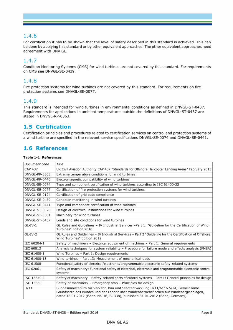
1.6 ReferencesTable 1-1 References
Document code TitleCAP 437 UK Civil Aviation Authority CAP 437 “Standards for Offshore Helicopter Landing Areas” February 2013DNVGL-RP-0363 Extreme temperature conditions for wind turbinesDNVGL-RP-0440 Electromagnetic compatibility of wind turbinesDNVGL-SE-0074 Type and component certification of wind turbines according to IEC 61400-22DNVGL-SE-0077 Certification of fire protection systems for wind turbinesDNVGL-SE-0124 Certification of grid code complianceDNVGL-SE-0439 Condition monitoring in wind turbinesDNVGL-SE-0441 Type and component certification of wind turbinesDNVGL-ST-0076 Design of electrical installations for wind turbinesDNVGL-ST-0361 Machinery for wind turbinesDNVGL-ST-0437 Loads and site conditions for wind turbinesGL-IV-1 GL Rules and Guidelines – IV Industrial Services –Part 1: “Guideline for the Certification of Wind
Turbines” Edition 2010GL-IV-2 GL Rules and Guidelines – IV Industrial Services – Part 2 “Guideline for the Certification of Offshore
Wind Turbines” Edition 2012 IEC 60204-1 Safety of machinery – Electrical equipment of machines – Part 1: General requirementsIEC 60812 Analysis techniques for system reliability – Procedure for failure mode and effects analysis (FMEA)IEC 61400-1 Wind Turbines – Part 1: Design requirementsIEC 61400-13 Wind turbines – Part 13: Measurement of mechanical loadsIEC 61508 Functional safety of electrical/electronic/programmable electronic safety-related systemsIEC 62061 Safety of machinery: Functional safety of electrical, electronic and programmable electronic control
systemsISO 13849-1 Safety of machinery – Safety-related parts of control systems – Part 1: General principles for designISO 13850 Safety of machinery – Emergency stop – Principles for designLR11 Bundesministerium für Verkehr, Bau und Stadtentwicklung LR11/6116.5/24, Gemeinsame
Grundsätze des Bundes und der Länder über Windenbetriebsflächen auf Windenergieanlagen, dated 18.01.2012 (BAnz. Nr. 16, S. 338), published 31.01.2012 (Bonn, Germany)
Standard, DNVGL-ST-0438 – Edition April 2016 Page 8
DNV GL AS

guidelines shall be considered.
For additional acceptable methods for fulfilling the requirements in this standard see also current ‘DNV GL rules and standards’ on www.dnvgl.com. Other recognized codes or standards may be applied provided it is shown that they meet or exceed the level of safety of the actual standard.
1.7 Definitions
1.7.1 Verbal forms
1.7.2 Terms
Table 1-2 Verbal forms
Term Definitionsshall verbal form used to indicate requirements strictly to be followed in order to conform to the documentshould verbal form used to indicate that among several possibilities one is recommended as particularly suitable,
without mentioning or excluding others, or that a certain course of action is preferred but not necessarily required
may verbal form used to indicate a course of action permissible within the limits of the document
Table 1-3 Terms
Term Definition
activation power safety-related trigger value for the protection system (PA)activation speed safety-related trigger value for the protection system (nA)braking system system capable of reducing the rotor speed or stopping rotation (e.g. aerodynamic system,
mechanical calliper brake or brake chopper resistors)cut-in lowest mean wind speed (normal wind profile model NWP as defined in DNVGL-ST-0437) at
which the wind turbine is switched oncut-out wind speed (normal wind profile model NWP as defined in DNVGL-ST-0437) exceeding which
the wind turbine shall be shut downcontrol system system that adjusts the wind turbine based on information about the condition of the wind
turbine and/or its environmentThe control system keeps the wind turbine within its operating limits.
design limits maximum or minimum values used in the design
dormant fault fault of a component or system which remains undetected during normal operation
grid electrical power network in the responsibility of the relevant network operator (RNO) which the wind turbine is connected to
grid loss, grid disturbance
deviations from the normal conditions in grid voltage and/or frequency are defined as grid disturbances or grid lossDepending on the electrical parameter measurement results, the control system in the wind turbine decides whether a grid disturbance (e.g. under-voltage ride through) or a grid loss (black-out) has occurred. The parameters to be measured are defined in a site-specific manner. The duration of a grid disturbance can vary between milliseconds and approx. 1–2 minutes.
individual pitch operation
operation mode that adjusts the pitch angle of every single rotor blade individually
locking device device which prevents moving parts (e.g. rotor, yaw system, blade pitching system) from movement
maximum speed highest rotational speed that may never be exceeded, not even brieflyoperating limits maximum or minimum values which define the operating range governed by the control system
overall control system expression used for the control and protection systems together if the differentiation between the two systems is not intended (see Figure B-2)
performance level discrete level used to specify the ability of safety-related parts of control systems to perform a protection function under foreseeable conditions (PL)
Standard, DNVGL-ST-0438 – Edition April 2016 Page 9
DNV GL AS

1.8 Acronyms, abbreviations and symbols
1.8.1 Acronyms and abbreviations
power continuous electrical power (active power) at the output terminals of the wind turbine measured at the grid side of a possible main circuit converter system and at the wind turbine side of a possible unit transformer
protection function function of the protection system which ensures that the wind turbine remains within the design limitsThe scope of this standard is focussing on extreme load related design limits only.
protection system system that controls the wind turbine if safety-related trigger values are exceeded or on demand of the control system The protection system keeps the wind turbine within the design limits. It guides the execution of protection functions (see Figure B-1). The scope of this standard is focussing on extreme load related design limits only.
rated lowest mean wind speed (normal wind profile model NWP as defined in DNVGL-ST-0437) at which the wind turbine produces rated power in the case of steady wind without turbulence (Vr)
rated power maximum continuous power the wind turbine is designed for under normal operating conditions (as defined in DNVGL-ST-0437)
rated speed rotational speed at operation at rated wind speed (nr)required PL applied in order to achieve the required risk reduction for each protection function (PLr)reset automatic or manual switching operation that changes a status in the control system or the
protection system from “triggered” to “not triggered”rotational speed speed at which the wind turbine’s rotor is rotating about the rotor axis; the speed may be given
in “speed of the rotor (low speed shaft speed)” or “speed of the generator (high speed shaft speed)”
safety-related fault condition
fault condition that endanger the structural integrity of the wind turbine by exceeding the design limits
wind speed all wind speeds are 10-min mean values given at hub height
wind turbine system which converts kinetic energy of the wind into electrical energy
Table 1-4 Acronyms and abbreviations
Short form In fullCCF common cause failureDC direct currentDCavg average diagnostic coverageDLL dynamic link libraryEMC electromagnetic compatibilityFMEA failure mode and effect analysisFRT fault ride-throughMTTFd mean time to dangerous failureOCS overall control systemPFHd probability of dangerous failure per hourPL performance levelPLr required performance levelPLC programmable logic control unitQM quality managementRMS root mean squareSCADA supervisory control and data acquisitionSPLC safety programmable logic controllerSRP/OCS safety-related parts of the overall control system
Table 1-3 Terms (Continued)
Term Definition
Standard, DNVGL-ST-0438 – Edition April 2016 Page 10
DNV GL AS

nA rotational speed, activation speednr rotational speed, rated speedPA activation powerVr wind speed, rated
Standard, DNVGL-ST-0438 – Edition April 2016 Page 11
DNV GL AS

2.1 GeneralThe design requirements are outlined in Sec.2 through Sec.6.
For the design of protection functions the requirements of this standard can be fulfilled by selecting one of the following two approaches:
— descriptive approach, as described in [2.2]— risk-based approach, as described in [2.3].
2.2 Descriptive approachWhen the descriptive approach is followed it has to be shown that the requirements in this standard are fulfilled as described in Sec.1 through Sec.6 except [2.3].
For certification, the documents as described in [A.1] shall be submitted to DNV GL as a minimum.
2.3 Risk-based approachWhen the risk-based approach is followed the chapter ‘Risk-based design of protection functions’ below shall be observed. The requirements given in Sec.1 through Sec.6 shall be followed if the related topic is not covered by the risk-based considerations.
Guidance note:In a certification project the customer has to choose which part follows the descriptive approach and which part follows the risk-based approach.
---e-n-d---of---g-u-i-d-a-n-c-e---n-o-t-e---
For the design of the emergency stop functionality the method of [2.13] shall be followed in every case.
For certification documents on the protection functions as described in [A.2] need to be submitted to DNV GL as a minimum.
Risk-based design of protection functions
For the documentation of the risk-based design of the systems that are performing protection functions the following working steps 1 through 4 are required as a minimum.
The four-working-steps-approach described here is a simplified method that can be applied. More advanced risk-based design methods may be followed for designing the control and protection systems for wind turbines. These shall at least result in the safety level described in this standard.
1) Identification of the protection functionsThe identification shall be supported by the failure consideration described in [2.4] by identification ofpossible failures in the wind turbine that require a protection function.
2) Determination of the required performance level (PLr)Each protection function identified shall undergo a determination of the required performance level (PLr)according to the method below using the consequence level “risk to investment”. This method analysisthe design before a protection function has been added.
Standard, DNVGL-ST-0438 – Edition April 2016 Page 12
DNV GL AS

Figure 2-1 Risk graph with respect to ISO 13849-1 for determining the required performance level (PLr) for the protection functions
Risk parameters S and F according to Table 2-1.
It is emphasized that the newly introduced consequence level risk to investment shall never reduce therequired safety level in terms of safety of personnel. In case of contradicting analysis results the moreconservative level shall always be chosen for design.
An example for the determination of required risk reduction is given in the informative App.E.
3) Design of the protection functionsProtection functions shall be designed minimizing the probability of the identified failures or theirconsequences sufficiently by meeting the required performance level that was determined.
General principles for design can be found in ISO 13849-1 or IEC 62061. A possible work flow is givenin App.D.
Guidance note:If applicable the scope of this consideration can include the pitch drives, pitch bearings and the supervision of the accumulators in the hub.
---e-n-d---of---g-u-i-d-a-n-c-e---n-o-t-e---
4) The documentation of protection functions may follow [A.2].
Table 2-1 Consequence levels
Risk parameters with respect to ISO 13849-1 Risk to investment
Severity of impactS1 Normally repairable turbine damage / total repair costs* < 1/3 of
investment sum
S2 Major or unrepairable turbine damage / total repair costs* ≥ 1/3 of investment sum
Probability of hazardous failure**
F1 Seldom-to-less-often i.e. < 10-3 p.a.F2 Frequent-to-continuous i.e. ≥ 10-3 p.a.
(Letter P is not used in this application.)* Total costs apart from others comprise material and labour costs as well as potential expenses on required equipage like trucks, cranes and offshore installation vessels. They do not compromise loss of earnings caused by stand still.** The evaluation of the probability of hazardous failure may also comprise the environmental conditions (e.g. If a possible failure can only develop to a dangerous event in certain wind speeds, consideration of the wind speed distribution will reduce the probability of hazardous failure.)
Standard, DNVGL-ST-0438 – Edition April 2016 Page 13
DNV GL AS

2.4.1 A list showing the consideration of possible failures and their effects shall be prepared. This shall be performed on system level for the following systems as a minimum:
— protection system including its sensors— braking systems (including the pitch system and, if applicable DC brake choppers in the main circuit
converter)— yaw system including the system for wind direction measurement— systems of nacelle acceleration monitoring (see [3.9])
and— if control and/or monitoring features are used to reduce the loads on the wind turbine (e.g. individual
pitch operation, laser based wind speed measurement, active tower damping), all systems used for these features.
In this consideration, all possible failures of these systems shall be specified.
2.4.2 For each possible failure, at least the following information shall be given:
— designation and description of the possible failure— affected component(s)— possible cause(s)— type of detection— effect(s) of the fault— measure(s) for limiting negative consequences— reference to the design load case in the documentation of the load calculation, if applicable.
2.4.3 The technique chosen for this consideration (e.g. failure mode and effect analysis (FMEA according to IEC 60812], fault tree analysis) shall be selected as appropriate by the author of the documents.
2.4.4 The failure consideration shall be used for the definition of load cases of the groups DLC 2.x and DLC 7.x (see DNVGL-ST-0437 or IEC 61400-1).
The failure consideration shall also be used for the evaluation of redundancies in the protection system and the evaluation of measures against possible dormant faults.
2.5 RedundancyA single failure of any component within the control system, protection system or a braking system, e.g. a sensor, shall not lead to the loss of a protection function. The simultaneous failure of two independent components is classed as an unlikely event, and it is therefore not necessary to consider this. Where components depend on one another, their simultaneous failure shall be classed as a single failure.
Guidance note 1:Independence means that faults with a common cause are avoided in the system-engineering design stage. Accordingly, the failure of a single component will not result in the failure of e.g. more than one braking system and thus the loss of the entire protection function.
---e-n-d---of---g-u-i-d-a-n-c-e---n-o-t-e---
Guidance note 2:ISO 13849-1 provides a comprehensive procedure for measures against common cause failure.
---e-n-d---of---g-u-i-d-a-n-c-e---n-o-t-e---
Standard, DNVGL-ST-0438 – Edition April 2016 Page 14
DNV GL AS

2.6.1 The control system controls the whole wind turbine including the braking systems and the main contactor for grid connection/disconnection.
2.6.2 The protection system shall have direct access to at least the braking systems and the main contactor for grid connection/disconnection.
2.6.3 The protection system shall be superordinate to the control system. That means that the control system – even if faulty – cannot violate any functions of the protection system.
2.6.4 The protection system is activated if safety-related trigger values are exceeded. These safety-related trigger values shall be adjusted
— clear outside the operating limits, that the control system is not disturbed by reactions of the protection system and
— that the reaction of the protection system can always keep the wind turbine inside the design limits.
2.7 Control and protection conceptThe concept of the control and protection system shall be drawn up. It shall contain at least the following items:
1) description of the hardware structure of the control system and the protection system2) description/schematics of the digital communication in the control and protection system3) description of important sensors4) specification of starting and stopping procedures5) specification of the scenario for the dimensioning of accumulators for braking systems ([2.12.2.4])6) description of the wind turbine behaviour at normal operation7) description of the wind turbine behaviour on detection of malfunctions8) description of the wind turbine behaviour on triggering of safety-related values9) description of the wind turbine behaviour on grid disturbance and grid loss (including fault ride-through
control concept for e.g. the pitch system) 10) description of the wind turbine behaviour at special environmental conditions (e.g. de-rating at high/
low ambient temperature, de-rating at high turbulence intensities)11) description of the wind turbines behaviour on resonance speeds12)parameter list including averaging method and period, if applicable, containing at least the following:
1) cut-out wind speed
2) design values and trigger values of rotational speed
3) design values and trigger values of power
4) control and trigger values of yaw
5) trigger values of nacelle acceleration
6) other safety-related protection system trigger values
7) trigger values of ambient temperature
8) other trigger values that influence the loads on the wind turbine
Standard, DNVGL-ST-0438 – Edition April 2016 Page 15
DNV GL AS

14)description of the protection system reset procedure.
Guidance note:The above mentioned items, esp. item no. 4 to 12, are also considered relevant for the load assessment, e.g. according to DNVGL-ST-0437.
---e-n-d---of---g-u-i-d-a-n-c-e---n-o-t-e---
2.8 Grid lossGrid loss (black-out) with a duration of up to 6 hours is regarded as a normal environmental condition (as defined in DNVGL-ST-0437). Grid loss with a duration exceeding 6 hours up to duration of 7 days shall be considered and is regarded as an extreme environmental condition (as defined in DNVGL-ST-0437).
Guidance note:For offshore and remote located wind turbines the grid loss concept should consider the duration of 3 months. Requirements on back-up power supply for long periods can be found in the standard on the design of electrical installations for wind turbines, i.e. DNVGL-ST-0076.
---e-n-d---of---g-u-i-d-a-n-c-e---n-o-t-e---
2.9 Control software, logic and principles for load related control loops
2.9.1 General2.9.1.1 The control software for load related control loops has a direct and substantial impact on the loads acting on the wind turbine. It shall thus be demonstrated, that this part of the control software operates as assumed during the load simulation process.
2.9.1.2 The software development process normally includes the following elements:
— quality managed development process (i.e. use of formalized software design methods and software style guides)
— testing by simulation (i.e. software in the loop testing)— functional testing (i.e. hardware in the loop testing)— full scale testing (i.e. test of turbine behaviour, load measurement, under-voltage ride-through)
2.9.1.3 The elements above or parts of them may be used to demonstrate to DNV GL that the control software for load related control loops operates at the wind turbine as assumed during the load simulation process.
2.9.2 Scope2.9.2.1 The scope of assessment during the certification of a wind turbine shall include any control software for load related control loops.
Guidance note:Examples of load related control loops include the pitch and generator torque control loop as well as any control loops comprising advanced control features for load reduction.
---e-n-d---of---g-u-i-d-a-n-c-e---n-o-t-e---
2.9.2.2 The scope of software testing shall be determined based on the results of FMEA or similar evaluations as performed according to [2.4] and shall comprise the functions, which may influence the loads of the wind turbine in normal operation or in case of any malfunction.
2.9.2.3 Testing shall as far as possible also include the hardware, firmware and any additional software layers involved in executing the control software at the actual wind turbine (i.e. including the control cabinets, sensors and other relevant elements). Actuator response, delays and external forces interfering with or supporting the control action shall be considered where relevant.
2.9.2.4 The aspects of safety, functionality, performance and robustness shall be addressed. Attention shall be given to the interfaces between different subsystems.
Standard, DNVGL-ST-0438 – Edition April 2016 Page 16
DNV GL AS

process2.9.3.1 The manufacturer shall establish quality management procedures for the development process of the control software for load related control loops. Testing of the software and hardware during the development is required.
2.9.3.2 The controller development process shall be documented and this documentation shall clearly describe the concept of verification for individual load relevant modules. The development process shall include appropriate methods and specifications for testing of the software and hardware including performance requirements for testing results.
2.9.3.3 Modifications to the control software for load related control loops due to unmet performance requirements or due to design changes shall follow these procedures as well.
Guidance note:For better maintainability, legibility and failure prevention, the software should be developed according to a software style guide.
---e-n-d---of---g-u-i-d-a-n-c-e---n-o-t-e---
2.9.4 Testing2.9.4.1 Testing shall comprise the operation of the control software for the load related control loops over all load-relevant operation modes of the wind turbine and/or as required for load calculation according to DNVGL-ST-0437.
2.9.4.2 Testing shall as far as possible also include hardware, firmware and any additional software layers involved in executing the control software at the actual wind turbine (i.e. including the control cabinets, sensors and other relevant elements). Actuator response, delays and external forces interfering with or supporting the control action shall be considered where relevant.
2.9.4.3 The wind turbine itself (i.e. the controlled system) may be simulated, if the behavior of load relevant subsystems (e.g. the pitch system) is sufficiently well known through previous tests.
2.9.4.4 The testing may be performed in the customer’s controller laboratory, on the prototype wind turbine, or in parts also at a sub-supplier’s laboratory.
2.9.4.5 In a test environment (e.g. hardware in the loop testing) the control system may have some detailed features and alarms disabled. This is allowable if it does not change the overall loads response of the system under test. Any disabled features or alarms shall be clearly described.
2.9.4.6 A test report comprising the presentation and analysis of results and conclusions, including a comparison of the results of the testing with results from of load simulations, shall be prepared.
2.9.4.7 Witnessing of selected tests shall be performed by DNV GL. The scope shall be agreed between the customer and DNV GL prior to the testing. This comprises the inspection of the software and hardware and the inspection of operational tests of normal operation and malfunctioning scenarios.
Guidance note:The tests can be performed as part of the certification module design assessment or as part of the certification module type testing (see DNVGL-SE-0441).
---e-n-d---of---g-u-i-d-a-n-c-e---n-o-t-e---
2.9.5 Assessment documentation2.9.5.1 Documentation of the functionalities implemented in the control software for load related control loops shall be provided and shall include flow charts, which describe the functionality in sufficient detail to understand the load relevant control processes. Detailed control algorithms do not have to be revealed.
2.9.5.2 An implementation of the control software for load related control loops shall be provided for assessment and independent load analysis. This may be a pure software implementation (i.e. a Windows DLL with clearly documented interface) or a combination of soft and hardware (i.e. a PLC implementing the control system, including the network interface and well defined communication protocol). The
Standard, DNVGL-ST-0438 – Edition April 2016 Page 17
DNV GL AS

parameters of the controller within an external file. The documentation shall include an operating manual and the description of the functional characteristics.
2.9.5.3 Furthermore, the following documentation associated with the control software for load related control loops shall be submitted:
— Parameter List:
— a list of the parameters used in the control software for load related control loops.
— QM documentation:
— software quality management plan
— software style guide; see [2.9.3]
— documentation of the transfer of the control software from load simulation to the wind turbine, see [2.9.6].
— system version control for the software as well as for the parameter list, see [2.9.7]
— documentation of the working process for creating and installing software updates, see [2.9.8].
— Test plan for software and hardware tests:
— test specification
— test schedule and responsibilities
— description of setup of test environment.
2.9.6 Transfer of control software from load simulation to wind turbineIt shall be documented how the control software for load related control loops, as used within the load simulation process, will be transferred to the hardware and its application software at the wind turbine. It shall be ensured that the functions and the performance are correctly transferred to the wind turbine’s hardware. If applicable, this includes intermediate stages, e.g. testing within a hardware in the loop environment, manual programming of the routines with subsequent testing or automatic compilation processes. Requirements on testing are given in [2.9.4].
2.9.7 System version control2.9.7.1 With respect to the control software for load related control loops, a quality management process shall be set up to clearly define and document the version numbers of the constituent elements of the control system (e.g. control software version, parameter definition version, subsystem firmware version). The documentation to be submitted shall comprise the requirements of sub-section items [2.9.7.2] to [2.9.7.5].
2.9.7.2 A system version control shall be implemented to document subsequent development steps and modifications of the system in a retraceable manner. The numbering of the system version control shall differentiate grades of relevance (e.g. special letters indicate bug fixes, new functions, etc.).
2.9.7.3 Modifications of the control software for load related control loops already certified are subject to certification. The respective parts of the whole process and, if relevant, also the load calculations may be subject to certification.
2.9.7.4 The system version control shall comprise a configuration management which allocates the permissible configuration of the wind turbine, e.g. tower, rotor blades etc., to the control software for load related control loops implemented in the application software at the wind turbine.
2.9.7.5 The user interface at the wind turbine shall give access to the actual system version installed. This information may be reviewed during DNV GL inspections.
Standard, DNVGL-ST-0438 – Edition April 2016 Page 18
DNV GL AS

A working process shall be defined for creating and installing software updates (see also [2.9.7.3]). In that process at least the aspects cyber safety and testing/release shall be considered as well as the aspects of clear status documentation of the implemented software version.
2.10 Protection system
2.10.1 General2.10.1.1 The protection system shall be operational or in activated mode (triggered) in all operational modes of the wind turbine, e.g. power production, parked, switched off, grid loss or maintenance.
2.10.1.2 The protection system shall be monitored by suitable measures. This monitoring shall be performed automatically by the protection system itself, by the control system or manually at the inspections during regular maintenance.
2.10.1.3 Once activated the protection system shall carry out its task without delay, keep the wind turbine in a safe condition and in general initiate deceleration of the rotor with the aid of the braking systems.
Guidance note:The protection system might disconnect the generator from the grid. This disconnection does not need to be carried out immediately at the activation of the protection system, but early enough to avoid excessive speeding-up of the wind turbine or operation of the generator as a motor.
---e-n-d---of---g-u-i-d-a-n-c-e---n-o-t-e---
2.10.1.4 After activation of the protection system a re-start of the wind turbine shall only be possible after a reset according to [2.11]. If the protection system has been activated before grid loss, then reset shall not be performed automatically after the return of the grid. It shall not be possible to start-up the wind turbine until the reset has taken place.
2.10.1.5 If devices with a programmable controller are used within the protection system (e.g. impulse counter for speed monitoring or intelligent relays), these components shall be assessed by functional testing. This testing may be carried out e.g. during the wind turbine type inspection (see DNVGL-SE-0441).
2.10.1.6 In systems where the frequency converter in the pitch system is used to actively drive the pitch system during a protection function (most electrical pitch systems with AC-drives), the software in the pitch frequency converter is an important part of the protection system.
For such systems the requirements of App.D 6) shall be fulfilled for the software of the pitch frequency converter also in the descriptive approach.
2.10.1.7 In systems where the logic of the protection system is software defined (e.g. a SPLC is used) this software is an important part of the protection system.
For such systems the requirements of App.D 6) shall be fulfilled for this software also in the descriptive approach.
2.10.1.8 All components of the protection system shall fulfil requirements concerning EMC immunity. This can be shown by applying DNVGL-RP-0440 (see also DNVGL-ST-0076).
2.10.2 Activation casesThe protection system shall be activated at least in the following cases at least:
— faulty control system — rotational speed too high (nA)— power too high (PA) — nacelle acceleration trigger value exceeded momentarily— short circuit in the main electrical power distribution path— abnormal cable twist— emergency stop device activated.
Standard, DNVGL-ST-0438 – Edition April 2016 Page 19
DNV GL AS

Details on the activation cases are given in [2.13] and Sec.3.
---e-n-d---of---g-u-i-d-a-n-c-e---n-o-t-e---
2.11 Reset of the protection system
2.11.1 After the protection system has been activated a manual reset is required. This manual reset shall be performed by a qualified person being physically present at the wind turbine.
2.11.2 The reset requirements after activation of an emergency stop device are given in the international standards referred to in [2.13].
2.11.3 Alternatively this qualified person need not be physically present in the turbine, but may perform the reset from the remote control centre, if the following prerequisites ([2.11.4] through [2.11.6]) are being met.
2.11.4 Before a remote reset is performed a detailed root cause analysis and investigation of the wind turbine has to be successfully accomplished.
2.11.5 The measures for evaluating the root cause of the activation of the protection system and the investigation of the wind turbine shall be capable of detecting cases with certainty such as rotor blade break-off (even parts of the rotor blade), moderately severe oil leakage, damage to main bearing, etc.
2.11.6 The number of allowable remote resets of the protections system shall be limited. For each possible fault status, the documentation shall state (see also Table 3-1)
— the number of allowable remote resets per 24 hand
— the number of allowable remote resets as a total, counted from the last reset of the protection system.
2.12 Braking systems
2.12.1 General2.12.1.1 There shall be at least two mutually independent braking systems by means of which the rotor can be decelerated or brought to a standstill at any time.
2.12.1.2 In the case of grid loss (black-out) and simultaneous failure of one of the braking systems, the remaining braking system(s) shall be able to keep the rotor below the maximum speed nA (see [1.7.2]).
2.12.1.3 If the concept of the wind turbine requires standstill of the drive train upon activation of an emergency stop device (see [2.13]), it shall be possible to bring the rotor to a standstill at the wind conditions described in [2.13].
For the dimensioning of the device to accomplish the standstill please refer to DNVGL-ST-0437:2016 Chapter [4.5.8].
2.12.1.4 At least one of the braking systems shall operate on an aerodynamic principle, and as such act directly on the rotor. If this requirement is not met, at least one of the braking systems shall act on the parts (hub, shaft) of the wind turbine that rotate at rotor speed (“low speed side”).
Standard, DNVGL-ST-0438 – Edition April 2016 Page 20
DNV GL AS

limiting clutch), any mechanical brake on the drive train shall be located between this component and the rotor hub.
2.12.1.6 All components of the braking systems shall fulfil requirements concerning EMC immunity. This may be shown by applying DNVGL-RP-0440.
2.12.1.7 If brake chopper resistors in the DC circuit of the main circuit frequency converter system are used for braking the turbine (e.g. during under-voltage ride through conditions), the thermal and other design requirements for these resistors shall be taken into account during assessment.
2.12.2 Energy supply for braking systems2.12.2.1 The braking systems shall be so designed that they remain operable at grid loss (without external power supply). If this requirement cannot be met by all braking systems, additional measures that ensure the safety level of this standard in an equivalent manner shall be implemented.
2.12.2.2 If power supply from accumulators (e.g. from the hydraulic unit or from batteries) is necessary for the functioning of braking systems, it shall be automatically monitored that a sufficient amount of energy is available in the accumulators (see also [3.12]). This monitoring may include temperature monitoring.
2.12.2.3 If the automatic monitoring of the energy storage cannot be carried out continuously, then automatic tests shall be performed at least weekly to show that a sufficient amount of energy is available. The wind turbine shall be shut down immediately if the automatic monitoring or test yields an abnormal result or the automatic test cannot be carried out. Automatic reset is not allowed after such shut down.
2.12.2.4 The amount of energy which is necessary to be stored in the accumulator is to be calculated from a scenario consisting of at least
— control operations at grid disturbances followed by
— one emergency braking process.
The scenario considered for dimensioning of the accumulator shall be included in the control and protection concept (see [2.7]).
2.12.2.5 Requirements on accumulators within braking systems may be found in DNVGL-ST-0076 and DNVGL-ST-0361.
Guidance note:In the following an example is given for the requirements for energy supply of braking systems:
Consider a wind turbine with three independent pitch drives. These are considered to be three independent braking systems.Upon occurrence of grid loss the rotor blades would pitch towards feathering position (see [2.12.2.1]: They are able to do this without grid supply).
If one of the pitch drives is faulty, the other two pitch drives have to keep the turbine in a safe condition (see [2.12.1.2]: Grid loss and failure of one braking system is to be considered to happen simultaneously).
---e-n-d---of---g-u-i-d-a-n-c-e---n-o-t-e---
2.13 Emergency stop
2.13.1 Functional requirements and design principles for the emergency stop function shall be in compliance with ISO 13850.
Guidance note:Suitable performance requirements for the emergency stop function’s safety-related parts can be found in ISO 13849 and IEC 62061.
---e-n-d---of---g-u-i-d-a-n-c-e---n-o-t-e---
Standard, DNVGL-ST-0438 – Edition April 2016 Page 21
DNV GL AS

The location of each emergency stop device and the stop category of each emergency stop function shall be clearly specified. At least one emergency stop device shall be provided at the tower bottom and one in the nacelle.
2.13.3 Upon activation of the emergency stop device the protection system shall be activated and all parts of the wind turbine that might perform hazardous movements (e.g. rotor, yaw system) shall be brought to a complete standstill.
Guidance note:Depending on the concept the wind turbine reactions upon activation of the emergency stop device may vary in relation to the position of the device (e.g. reaction upon activation at the tower bottom can be different to the reaction upon activation in the nacelle).
---e-n-d---of---g-u-i-d-a-n-c-e---n-o-t-e---
2.13.4 The braking process shall be performed in the shortest time. The primary aim is not a gentle stop but rather the most rapid braking to a standstill, which is compatible with the strength of the wind turbine’s components.
2.13.5 The braking process shall be possible under all wind conditions at which access to the wind turbine’s nacelle is allowed.
Guidance note:If, in addition to this DNV GL standard the international standard IEC 61400-1:2005, is to be fulfilled, then Chapter 8.3 of that standard should be considered as well.
---e-n-d---of---g-u-i-d-a-n-c-e---n-o-t-e---
Standard, DNVGL-ST-0438 – Edition April 2016 Page 22
DNV GL AS

3.1 GeneralThe momentarily condition of the wind turbine depends on the environmental conditions outside (e.g. wind speed, ambient temperature) as well as the behaviour of the wind turbine itself (e.g. pitch angle, yaw direction, rotational speed).
In the following the devices monitoring the most important of the conditions and behaviour are listed and related requirements are given.
3.2 Performance of resets
3.2.1 In some cases described in the following the control system is permitted to perform automatic resets following a turbine shut-down. These automatic resets are limited in number (see Table 3-1). These limitations in number are meant to be counted individually for each of the different limiting values independently from each other.
3.2.2 The following reset limitations shall be observed where applicable. Different triggered or activated devices or functions, not mentioned below, may also be applicable and rated accordingly.
Table 3-1 List of possible resets at monitoring functions
Triggered or activated device or function Reset type Reset limit Condition
Protection system activated ([2.10]) Manually at the turbine none none
Manually from remote
to be stated by customer see [2.11]
Faulty rotational speed measurement ([3.3]) Manually none
No safety-related fault condition,rotational speed measurement
repairedRotational speed exceeds the upper operating limit ([3.3]) Automatic 3 in 24hrs No safety-related fault condition
Faulty wind speed measurement ([3.5]) Manually none No safety-related fault condition,
wind speed measurement repairedCut-out wind speed exceeded ([3.5])
Automatic noneNo safety-related fault condition,
wind speed has fallen to a permissible value
Faulty wind direction measurement ([3.6]) Manually none No safety-related fault condition,
wind direction measurement repairedCut-out wind direction ([3.6])
Automatic none
No safety-related fault condition,the rotor axis has been re-aligned with the wind direction into the operating
limitsBlade pitch angle exceeded limiting values ([3.7]) Automatic 3 in 24hrs No safety-related fault condition
Individual pitch operation exceeded limiting values ([3.8]) Automatic 3 in 24hrs Faulty condition does not exist
anymoreNacelle acceleration exceeds a limit ([3.9]) Automatic 3 in 24hrs No safety-related fault condition
Grid loss ([3.10]) Automatic none No safety-related fault condition,grid recovered
Braking system monitoring triggered ([3.12]) Manually none No safety-related fault condition,
braking system repairedCable twisting exceeded limiting value ([3.14]) Automatic none No safety-related fault condition,
untwist operation finalised
Standard, DNVGL-ST-0438 – Edition April 2016 Page 23
DNV GL AS

3.3 Rotational speed
3.3.1 The rotational speed shall be measured at least twice by systems mutually independent from each other.
3.3.2 The rotational speed signal shall be supplied at least twice to the control system and at least once to the protection system.
3.3.3 At least one of the rotational speed measurement systems shall measure the speed of a component of the wind turbine that runs at rotor speed.
3.3.4 The control system shall continuously monitor the plausibility of at least two of the measured speed signals with regard to each other. If this monitoring detects an error and less than two sound rotational speed signals are available, the wind turbine shall be shut down immediately. It may be restarted after manual reset.
3.3.5 The control system shall shut down the wind turbine immediately if the rotational speed exceeds the upper operating limit. An automatic re-start may take place after automatic reset. See Table 3-1 above.
3.3.6 The trigger value for the protection system (nA) shall be adjusted such, that the maximum speed may never be exceeded.
3.4 Power
3.4.1 The power shall be measured continuously at least twice by systems mutually independent from each other.
3.4.2 At least one power signal shall be monitored by the control system.
Self-monitoring of control system triggered ([3.17]) Automatic 3 in 24hrs No safety-related fault condition
Automatic ice detection triggered ([3.19]) Manually at the
turbine noneNo safety-related fault condition,visual inspection shows that rotor
blades are ice free
Manually from remote or automatic none
No safety-related fault condition,suitable sensor signal shows that rotor
blades are ice freeLeakage detected at floating wind turbine ([5.3.1]) Manually none No safety-related fault condition,
leakage repairedMooring system monitoring triggered at floating wind turbine ([5.3.2]) Manually none No safety-related fault condition,
mooring system repairedMotion and heeling monitoring exceeds a limit at floating wind turbine ([5.3.3])
Automatic 3 in 24hrsNo safety-related fault condition,
values have fallen into permissible range
Table 3-1 List of possible resets at monitoring functions (Continued)
Triggered or activated device or function Reset type Reset limit Condition
Standard, DNVGL-ST-0438 – Edition April 2016 Page 24
DNV GL AS

Independent of this, another power signal shall be monitored by another device outside the control system (e.g. the control unit of the frequency converter or the control unit of the main contactor).
3.4.4 If one of the monitoring systems detects exceedance of the activation power PA the wind turbine shall be shut down immediately and the protection system shall be activated.
3.5 Wind speed
3.5.1 The wind speed shall be measured continuously at hub height with at least one measurement system, e.g. mechanical or ultrasonic anemometer.
3.5.2 The control system shall continuously monitor the plausibility of the wind speed signal by comparison with a second wind speed signal measured independently, or by comparison with other measurands related to the wind speed. If this monitoring detects an error, the wind turbine shall be shut down immediately. It may be restarted after manual reset.
3.5.3 The wind speed sensor(s) should be equipped with a suitable heating which will be activated in case of the danger of icing.
3.5.4 If the wind turbine was shut down after exceeding a cut-out wind speed, an automatic re-start may take place after automatic reset. See Table 3-1 above.
3.6 Wind direction
3.6.1 The wind direction in relation to the nacelle orientation (yaw error) shall be measured continuously at hub height with at least one measurement system, e.g. wind vane or ultrasonic wind sensor.
3.6.2 The control system shall continuously monitor the plausibility of the wind direction signal by comparison with a second wind direction signal measured independently, or by comparison with other measurands related to the wind direction. If this monitoring detects an error, the wind turbine shall be shut down immediately. It may be restarted after manual reset. See Table 3-1 above.
3.6.3 The wind direction sensor(s) should be equipped with a suitable heating which will be activated in case of the danger of icing.
3.6.4 Values for the cut-out wind direction shall be stated by the customer. These values define the wind direction sectors in which operation of the wind turbine is allowed. They may be stated in relation to wind speed, delay times or other conditions.
3.6.5 If the wind turbine was shut down after exceeding a cut-out wind direction, an automatic re-start may take place after automatic reset. See Table 3-1 above.
Standard, DNVGL-ST-0438 – Edition April 2016 Page 25
DNV GL AS

3.7.1 At pitch-controlled wind turbines, the control system shall continuously monitor the blade pitch angle. At wind turbines equipped with an independent blade pitching system the blade pitch angle of each rotor blade shall be monitored.
3.7.2 The plausibility of the measured values shall be supervised. For this propose the control system shall monitor the plausibility of the measured blade pitch angles by comparison with a second blade pitch angle signal measured independently (in case of independent blade pitching system at the same rotor blade). If these monitoring tasks cannot be carried out continuously, then automatic tests shall be performed at least weekly (e.g. monitoring of the signal of an end switch). The wind turbine shall be shut down immediately if the monitoring or a test reveals an abnormal result. It may be restarted after manual reset.
3.7.3 If the blade pitch angle of any rotor blade exceeds the limiting values for the deviation between the demanded value of the pitch angle and the measured pitch angle, the wind turbine shall be shut down by the control system.
3.7.4 If the deviation between the measured pitch angles of the different rotor blades exceeds the limiting value, the wind turbine shall be shut down by the control system.
3.7.5 If the wind turbine was shut down after exceeding one of the limiting values, an automatic re-start may take place after automatic reset. See Table 3-1 above.
3.8 Individual pitch operation
3.8.1 If the wind turbine uses individual pitch operation, the measurement of critical values of the individual pitch operation shall be self-monitoring or redundant. These critical values may be the blade root bending moment or the main shaft bending moment, the rotor position as well as the blade pitch angle.
3.8.2 The control system shall continuously monitor the plausibility of the individual pitch operation. The wind turbine shall immediately be shut down or be switched to a reduced operational mode if this monitoring reveals an abnormal result.
3.8.3 After such shut down or switch to a reduced operational mode the wind turbine may upon automatic reset re-start or return to normal operation, see Table 3-1 above, if the faulty condition does not exist anymore. The automatic reset shall be limited to three times every 24 hours.
3.9 Nacelle acceleration
3.9.1 General3.9.1.1 The nacelle of the wind turbine is moving during operation as result of dynamic tower bending. Mostly these movements are cyclic. These movements shall be monitored by monitoring the nacelle acceleration continuously in both horizontal translational directions.
3.9.1.2 The sensor shall be located at nacelle height and should be located eccentric to the tower axis.
Standard, DNVGL-ST-0438 – Edition April 2016 Page 26
DNV GL AS

3.9.2.1 The acceleration shall be continuously monitored by the protection system. If the momentary acceleration trigger value (measurement period less than one second) is exceeded, the protection system shall be activated.
3.9.2.2 The acceleration protection system trigger value shall be set outside the operating limit range but still keeping the wind turbine within its design limits.
3.9.3 Monitoring by the control system3.9.3.1 The control system shall monitor the accelerations and compare these continuously with limiting values. These limiting values shall be defined for two averaging periods:
— short-term monitoring (e.g. measurement period up to a few seconds) (focus on extreme load)and
— long-term monitoring (e.g. measurement period in the range of several minutes) (focus on fatigue load).
3.9.3.2 The following shall be defined:
— selected time periods for short-term and long-term monitoring
— selected method to average the acceleration signals (e.g. root mean square (rms) values)
— selected frequency band widths and the limiting values in each band widthand
— description of the method, how these parameters were developed.
Guidance note 1:It is advisable to define the limiting values in relation to the operating condition of the wind turbine (e.g. wind speed, rotational speed or power).
---e-n-d---of---g-u-i-d-a-n-c-e---n-o-t-e---
Guidance note 2:The limiting values can be found by simulations. For these simulations, malfunctions (e.g. mechanical and/or aerodynamic imbalance of the rotor, displacement of natural frequencies) can be defined, depending on the system concept and tower or rotor blade design. In the simulations, it can then be shown that these malfunctions are detected by the vibration monitoring with the selected sensitivities, averaging periods and limiting values, without exceeding the loads defined for the design.
---e-n-d---of---g-u-i-d-a-n-c-e---n-o-t-e---
3.9.3.3 If any of the limiting value is exceeded the wind turbine shall be shut down by the control system. An automatic re-start may take place after automatic reset. See Table 3-1 above.
3.10 Grid loss (black-out) In case of grid loss the control system shall shut down the wind turbine immediately. An automatic re-start may take place after automatic reset. See Table 3-1 above.
3.11 Short circuitUpon short circuit trip of the electrical protection devices (e.g. a circuit breaker) in the main electrical power distribution path the protection system shall be activated.
3.12 Fault ride-through
3.12.1 Evaluation of electrical behaviour during fault ride-through (FRT) events like under-voltage ride-through or over-voltage ride-through may be assessed by applying DNVGL-SE-0124.
Standard, DNVGL-ST-0438 – Edition April 2016 Page 27
DNV GL AS

Possible influences expected on the wind turbine’s structural integrity during FRT events shall be described and relevant documentation submitted to DNV GL for assessment (e.g. load measurements during FRT testing and/or corresponding simulations).
3.13 Monitoring of braking systems
3.13.1 The control system shall monitor the condition of braking systems continuously if
— wear in parts of the braking system could lead to poor functioningor
— an accumulator is necessary for safe functioning (see also [2.12.2]).
3.13.2 The design of the monitoring device and the triggering criterion shall be adjusted such that at least one wind turbine shut down is possible upon a triggering event.
3.13.3 In case the monitoring device detects a fault, the control system shall shut down the wind turbine. It may be restarted after repair of the braking system and manual reset. See Table 3-1 above.
3.14 Cable twisting
3.14.1 GeneralThe degree of cable twisting in free hanging cable loops shall be monitored at least twice by systems mutually independent from each other. One of the signals shall be supplied to the protection system and at least one to the control system.
3.14.2 Monitoring by the protection systemThe protection system shall be activated immediately if its trigger value is exceeded.
3.14.3 Monitoring by the control systemThe control system shall activate the automatic untwist operation upon exceedance of limiting values. During the untwisting, the wind turbine shall be shut down. An automatic re-start may take place after automatic reset. See Table 3-1 above.
Guidance note:To prevent possible danger to the wind turbine’s structure, it may be advisable to suppress the automatic untwisting at extremely high wind speeds (e.g. higher than cut-out wind speed). Then the yaw system could control the wind turbine automatically until these wind speeds have dropped to an acceptable level.
---e-n-d---of---g-u-i-d-a-n-c-e---n-o-t-e---
3.15 Ambient temperature measurementThe ambient air temperature shall be measured at the outside of the nacelle in the air stream such that direct radiation from the sun does not affect the accuracy of the measurement.
3.16 Operation of a cold wind turbineIf a relationship between the wind turbine’s component temperature and the related admissible operation condition is specified by the manufacturer for certain components (e.g. gearbox, bearings, generator, transformer, electrical cabinet), then a corresponding “warm-up phase” shall be provided in the control system of the wind turbine. The operation condition of any component (e.g. momentarily power, on/off condition) shall at no time be outside the parameters specified for the momentary component temperature by the manufacturer of the corresponding component.
Standard, DNVGL-ST-0438 – Edition April 2016 Page 28
DNV GL AS

3.17.1 The control system shall activate the protection system in case it detects that it has lost control of the wind turbine (e. g. an actuator does not execute a command).
3.17.2 If different main parts of the control system (e.g. different PLCs in the hub and the nacelle) lose their mutual communication, then both parts shall initiate a turbine shut-down.
3.17.3 The live status of the control system shall be monitored by a suitable arrangement (e.g. watchdog). If this is triggered, the wind turbine shall be shut down immediately. An automatic re-start may take place after automatic reset. See Table 3-1 above.
3.18 Data storageEach time the protection system is activated the control system shall store the data of the final operating conditions. The data of e.g. the last 7 min before and the first 3 min after the activation event should be stored.
3.19 Automatic ice detection
3.19.1 Optionally the wind turbine may be equipped with a system for automatic ice detection. If such a system is part of the certification and if shut down of the wind turbine upon ice detection is required, sub-section [3.19.2] to [3.19.7] shall be fulfilled.
3.19.2 The sensor shall be capable of detecting icing or an ice-forming atmosphere at hub height or at the rotor blades. This shall be verified by tests or data sheets of the sensor manufacturer.
3.19.3 The ice sensor unit shall at least provide a health signal and an alarm signal output. The control system shall continuously monitor these output signals.
3.19.4 The control system shall shut down the wind turbine if the ambient temperature is below +5°C and simultaneously
— the ice sensor signals alarmor
— the ice sensor signals faultyor
— the communication to the ice sensor is not available.
3.19.5 If the sensor cannot monitor the complete rotor blades, a plausibility test in the control system is required additionally. This test may e.g. consist of a monitoring of the plausibility between wind speed and power (including pitch angle and rotational speed). The parameters and limiting values shall be specified. In case this monitoring detects ice formation, the control system shall shut down the wind turbine.
Standard, DNVGL-ST-0438 – Edition April 2016 Page 29
DNV GL AS

After any such shut down the turbine may be restarted after manual reset. See Table 3-1 above.
3.19.7 Manual reset and re-start can be performed after an inspection of the rotor blade showed that they are ice free. Reset and re-start may be performed manually from remote or automatically, if the wind turbine is equipped with a sensor system which can indicate that the rotor blades are free of ice. See Table 3-1 above.
Standard, DNVGL-ST-0438 – Edition April 2016 Page 30
DNV GL AS

4.1 A wind turbine shall be equipped with locking devices for all moving components like
— rotor— yaw system— blade pitching systems.
4.2 These locking devices shall be activated manually or automatically.
4.3 Personnel physically present at the locking device shall have the possibility to secure the locking device manually in the locked (engaged) position. After such securing it shall be impossible to open (dis-engage) the locking device remotely or automatically.
4.4 The status of both the locking device (locked/open) and the securing device (secured/free) shall be clearly visible for any person physically present at the locking device.
4.5 Sub-section [7.5] of DNVGL-ST-0361:2016 states further requirements for the design of the locking devices.
Standard, DNVGL-ST-0438 – Edition April 2016 Page 31
DNV GL AS

5.1 Remote control
5.1.1 It shall be possible, if necessary, to bring the rotor to a standstill by remote control prior to the arrival of a ship or a helicopter. Further it shall be possible, if necessary, to position the rotor safely in any position required by a helicopter crew.
5.1.2 It shall be possible, if necessary, to yaw the nacelle by remote control in order to bring it safely in any position required by a ship or helicopter crew prior to their arrival.
5.2 Safety requirements for heli-hoist platforms
5.2.1 The design of the heli-hoist platform (helicopter winching areas) on a wind turbine shall be in accordance with the requirements of the relevant authorities.
Guidance note:The following regulations for heli-hoist platforms are known and may be considered:
— CAP 437— LR11.
---e-n-d---of---g-u-i-d-a-n-c-e---n-o-t-e---
5.2.2 Design requirements for heli-hoist platforms are given in DNVGL-ST-0361:2016 sub-section [11.5.1].
5.3 Requirements for floating structures
5.3.1 Tightness5.3.1.1 If leakage may lead to an unsafe condition for the floating structure’s hollow bodies, such as sub-structure segments or buoyancy elements, they shall be equipped with an adequate system monitoring their tightness.
5.3.1.2 The control system shall detect leakage and trigger an alarm. If safe operation cannot be ensured due to leakage, the offshore wind turbine shall be shut down by the control system. It may be restarted after repair and manual reset. See Table 3-1 above.
5.3.2 Mooring system5.3.2.1 The loss of one mooring system shall not challenge the capability of the remaining mooring system(s) of keeping the offshore wind turbine in its allocated area.
5.3.2.2 In case of loss of one mooring system, the control system shall trigger an alarm. If safe operation cannot be ensured due to the loss of one mooring system, the offshore wind turbine shall be shut down by the control system. It may be restarted after repair and manual reset. See Table 3-1 above.
5.3.3 Motion and heeling monitoring5.3.3.1 The motions and accelerations in 6 degrees of freedom shall be monitored continuously by the control system.
5.3.3.2 Additionally, the actual angle of heeling with respect to the assumed coordinate system of the floating offshore wind turbine shall be monitored.
Standard, DNVGL-ST-0438 – Edition April 2016 Page 32
DNV GL AS

continuously with the instantaneous values measured. If limiting values are exceeded, the control system shall shut down the offshore wind turbine (see also [3.9]). An automatic re-start may take place after automatic reset. See Table 3-1 above.
5.3.3.4 The measures described in [5.3.3.1] through [5.3.3.3] need to be activated for all modes of operation of the offshore wind turbine.
5.3.4 Environmental monitoringIf required for safe operation of the offshore wind turbine, waves and current shall be monitored at least once per wind farm.
Standard, DNVGL-ST-0438 – Edition April 2016 Page 33
DNV GL AS

6.1 Prototype under test
6.1.1 The design of the wind turbine at which the test of turbine behaviour is carried out shall conform to the greatest possible extent with the design which the certification is based on. The compliance or any deviations shall be reported to DNV GL and the accredited testing laboratory before the testing takes place.
6.1.2 The testing laboratory or the customer performing the test of turbine behaviour shall record the identifications and data on the nameplates of the test turbine’s main components (at least the rotor blades, gearbox, generator, tower and control software version) and shall include these in the measurement report.
6.1.3 The scope of the test of turbine behaviour can be reduced for turbine type variants or design variants after consultation with DNV GL, provided that the test was performed in its entirety for a predecessor turbine type. Generally, the scope of the tests may be reduced to those tests which are influenced by the design modifications.
6.1.4 The test of turbine behaviour shall preferably be carried out at the prototype wind turbine fitted with instrumentation for load measurements.
6.2 Test planBefore the start of the test of turbine behaviour the test plan shall be submitted to DNV GL for assessment. The test plan shall contain at least the following information:
— description of the test turbine and measurement/test equipment
— description of the test site
— name of the accredited testing laboratory, if applicable
— extent of the measurements and a precise description of the test
— parameter settings for the tests
— expected results
— envisaged evaluations.
6.3 Testing laboratoryThe test of turbine behaviour shall be carried out and documented by a testing laboratory accredited for load measurements on wind turbines. Alternatively, the test of the turbine behaviour can be carried out by the customer after prior consultation with DNV GL and be witnessed by an accredited testing laboratory or by DNV GL.
6.4 Offshore application
6.4.1 The test of turbine behaviour performed at a (prototype) test turbine onshore may be sufficient for the offshore turbine, depending on the compliance of the prototype test turbine design with the design on which the offshore certification is based. All design deviations shall be reported to DNV GL and the accredited testing laboratory before the testing takes place. See also [6.1].
Standard, DNVGL-ST-0438 – Edition April 2016 Page 34
DNV GL AS

At least those parts of the test of turbine behaviour which cannot be performed onshore (e.g. in case of floating wind turbines) shall be performed offshore at an offshore wind turbine.
6.5 Activities after the testingOn completion of the test of turbine behaviour the following activities shall be performed by the customer or the testing laboratory:
— documentation of the tests (test report)— comparison of the test results with the assumptions in the design documentation— clarification of possible deviations/ abnormalities.
The respective documents are to be submitted to DNV GL for assessment.
6.6 Performance of the test of turbine behaviour
6.6.1 The tests listed and specified in App.C shall be performed.
6.6.2 The test of turbine behaviour comprises the following individual tests:
— test of the protection system ([C.1])— test of the braking systems ([C.2])— test of the switching operations ([C.3])— other tests which were specified during the design phase of the wind turbine ([C.4])— measurement of the natural frequencies ([C.5]).
6.6.3 The requirements of IEC 61400-13 shall be applied with the necessary changes to the areas of:
— calibration— requirements for the measurement parameters and the measurement system— reporting.
6.7 Hydraulic pressure at the mechanical brakes
6.7.1 As an alternative to measurement of the hydraulic pressure, an alternative measurement parameter may be recorded if the signal exhibits a clear relationship to the applied braking moment (e.g. position of a control valve). This relationship shall be documented in the test report.
6.7.2 In the case of brakes that are activated at fixed levels (e.g. hard braking / soft braking / off) simple logging of the brake status shall suffice. The status signal shall be sensed at the brake or at the hydraulic system. The pressures or the braking moments of the individual levels shall be documented in the test report.
Standard, DNVGL-ST-0438 – Edition April 2016 Page 35
DNV GL AS

A.1 General documentsFor the assessment of the control and protection system, the following documents shall be submitted to DNV GL:
a) description of the wind turbine (type designation, general layout of the wind turbine, functional principles, …)
b) failure consideration as per [2.4]c) electrical and hydraulic (and, if applicable, also pneumatic) circuit diagrams at least to the extent that
the function of the protection system is shown. In the circuit diagrams, the connections between the electrical and hydraulic (and, if applicable, also pneumatic) system shall be clearly recognizable. For hydraulic systems requirements may be found in DNVGL-ST-0361:2016 Chapter [7.8] and for electrical diagrams in DNVGL-ST-0076
d) description of the remote monitoring and control possibilities e.g. by SCADA of individual turbines (e.g. alternation of electrical power output, pitch / yaw control parameters, …) if applicable. This information is required as far as the loads and / or the protection system of the wind turbines are influenced
e) control and protection concept (see [2.7])f) description of the individual pitch operation system – if available – with specification of the functions,
parameters and all sensors involvedg) description of the braking systems and their behaviour (structure of the braking systems, mode of
operation, characteristic quantities, time constants, …)h) documentation of the control software for load related control loops, see [2.9.5]i) documentation of software used in the protection system (if applicable) as per [2.10.1]j) description of any inside and outside monitoring cameras and microphones, if applicablek) documentation of possible influences of FRT events, see [3.12]l) Specification of the test turbine for the test of turbine behaviour, see [6.1]m) test plan (test of turbine behaviour), see [6.2]n) test report (test of turbine behaviour) and comparison of the test results with the assumptions in the
design documentation, see [6.5]o) functional description of the locking devices as per Sec.4 p) Alarm list. This list shall describe each alarm as a minimum by following means (as far as applicable):
i) nameii) I/O or data point numberiii) description respectively logic in order to under-stand the meaning of the message, warning, alarmiv) stop or braking program to be activatedv) yaw program to be activatedvi) requirements on reset (automatic, manual at the turbine, manual from remote, …).
A.2 Documents for the risk-based approachIf the design of the protection system is based on the risk-based approach of [2.3] the following documents shall be submitted to DNV GL:
a) a table listing all protection functions including each required performance level (PLr)b) a safety-related block diagram including possible subsystems for each protection functionc) circuit diagrams (electric, hydraulic, pneumatic) showing the wiring of all safety related parts of the
overall control system (SRP/OCS) performing the protection functionsd) a table for every protection function/subsystem which lists up the performing SRP/OCS including the
parameters the calculation is based one) a table which lists the protection function/subsystem with evaluation resultsf) documentation of software.
Standard, DNVGL-ST-0438 – Edition April 2016 Page 36
DNV GL AS

The documents shall show that the requirements set out in Sec.2 through Sec.6 are being met. The degree of detail shall be so selected that the behaviour of the wind turbine is adequately defined with regard to the load assumptions.
Standard, DNVGL-ST-0438 – Edition April 2016 Page 37
DNV GL AS

SYSTEMS, SCHEME
Figure B-1 visualizes schematically the interaction of the control and protection systems and is intended to be helpful for understanding the wording in Sec.2 with respect to the descriptive approach. However, the wording of Sec.2 is binding.
Figure B-1 Interaction of the control and protection systems (descriptive approach)
Figure B-2 visualizes schematically the definition of the overall control system (OCS) as the merger of the control and the protection systems and is intended to be helpful for understanding the wording in Sec.2 with respect to the risk-based approach.
However, the wording of Sec.2 is binding.
Figure B-2 Overall control system (OCS, risk-based approach)
Standard, DNVGL-ST-0438 – Edition April 2016 Page 38
DNV GL AS

C.1 Test of the protection systemFor the tests of the protection system at least the following measurement parameters shall be recorded:
— wind speed— rotational speed— electrical power output— blade angle or position of the aerodynamic brakes, if applicable— hydraulic pressure at the mechanical brake(s) (see [6.7])— torque of the main shaft or driving torque of the rotor— blade root bending moments.
The following measurements shall be carried out:
C.2 Test of the braking systemsFor the tests of the braking systems, at least the following measurement parameters shall be recorded:
— wind speed— rotational speed— electrical power output— blade angle or position of the aerodynamic brakes, if applicable— hydraulic pressure at the mechanical brake(s) (see [6.7])— torque of the main shaft or driving torque of the rotor— blade root bending moments.
No. Test Number of testswind speed < 80% Vr
Number of testswind speed ≥ 80% Vr
Remarks
C1.1 Activation of the protection system through exceedance of nA
- 2
The rotational speed nA as defined in [1.7.2] shall be used as the set point for the test.
C1.2 Activation of the protection system through actuation of an emergency stop device
2Activation during power production
C1.3 Activation of the protection system by the nacelle acceleration trigger value
2
Standard, DNVGL-ST-0438 – Edition April 2016 Page 39
DNV GL AS

C.3 Test of the switching operationsFor the tests of switching operations, at least the following measurement parameters shall be recorded:
— wind speed— wind direction at the wind measurement mast (for the test of yaw control)— nacelle position (for the test of yaw control)— rotational speed— electrical power output— blade angle or position of the aerodynamic brakes, if applicable — hydraulic pressure at the mechanical brake(s) (see [6.7])— torque of the main shaft or driving torque of the rotor— blade root bending moments.
No. Test Number of testswind speed < 80% Vr
Number of testswind speed ≥ 80% Vr
Remarks
C2.1 Braking with fault in one aerodynamic braking system 2 2
For wind turbines with more than one aerodynamic braking system.Remarks 1), 4), 5)
C2.2 Braking with fault in braking system I 2 2 For wind turbines with
exactly two braking systemsC2.3 Braking with fault in braking
system II 2 2
C2.4 Braking with other assumable malfunctions in the braking systems
2 tests for each assumable malfunction (wind speeds to be defined realistically)
Remark 2)
C2.5 Effectiveness of the mechanical brake(s) 2 Remark 3)
Remark 1): The blade root bending moments shall be measured at one of the blades with and at the blade without blade pitching function. If only one blade is fitted with instrumentation, the number of tests shall be doubled in each wind speed range, whereby the failure of the aerodynamic braking system shall be tested at the instrumented blade and then at another.
Remark 2): These tests may be necessary if other malfunctions have been assumed in the consideration of possible faults as per [2.4] (e.g. failure of the blade pitching motor to switch off when feathering).
Remark 3): The magnitude of the braking moment and the build-up curve of the braking moment shall be shown by means of a suitable test.
Remark 4): For wind turbines with full-span pitch control, the tests for wind speed ≥ 80% of Vr may be omitted after consultation with DNV GL.
Remark 5): The tests shall preferably be performed at rated speed nr.
Standard, DNVGL-ST-0438 – Edition April 2016 Page 40
DNV GL AS

condition has been reached. The following measurements shall be carried out:
C.4 Other tests which were specified during the design phase of the wind turbineIf during the design phase of the wind turbine any testing was specified to be performed in order to validate or verify any specific turbine feature, which cannot be shown by any standard test, then this testing shall be carried out and documented as part of the test of turbine behaviour.
For these tests the measurement parameters shall be specified to sufficiently show the specific turbine feature in question. The following measurements shall be carried out:
C.5 Measurement of the natural frequenciesFor measurement of the natural frequencies, the measurement parameters that are appropriate in each case shall be recorded and evaluated. The natural frequencies (eigenfrequencies) shall be determined by counting of vibration cycles or by frequency analyses of suitable measurement signals.
If a vibration damper system is fitted in one of the components (e.g. the tower), the related eigenfrequencies shall be determined both with activated and de-activated vibration damper system for all eigenmoduli which are influenced by this damper system.
No. Test Number of testswind speed < 80% Vr
Number of testswind speed ≥ 80% Vr
Remarks
C3.1 Start-up of the turbine 2 2C3.2 Shut-down with each of the
defined braking procedures 2 tests per braking procedure Remark 1)
C3.3 Switch-over of the generator-grid connection 2 switch-overs in either direction
For wind turbines with 2 or more fixed speeds and / or star-delta connection
C3.4 Braking in the case of grid loss 2 2
C3.5 Activation of the yaw system- 1 yaw operation in either
direction
Function of the automatic wind tracking shall be shown
C3.6 Shut-down upon cut-out wind direction 1 test in either direction
Remark 1): For wind turbines with blade pitch control, the blade pitching rates shall be documented in the report.
No. Test Number of testswind speed < 80% Vr
Number of testswind speed ≥ 80% Vr
Remarks
C4.x To be specified during the wind turbine design phase To be specified To be specified
Standard, DNVGL-ST-0438 – Edition April 2016 Page 41
DNV GL AS

No. Component Wind turbine switched off Wind turbine in power productionC5.1 Rotor blade — 1st and 2nd eigenfrequency flapwise
— 1st and 2nd eigenfrequency edgewise— 1st and 2nd eigenfrequency flapwise— 1st and 2nd eigenfrequency edgewise
C5.2 Drive train 1st torsional eignefrequency with generator switched off and mechanical brake opened (excitation e.g. through closing and opening of the mechanical brake during idling)
1st torsional eignefrequency with generator switched on
C5.3 Tower — 1st eigenfrequency for bending in wind direction (fore – aft); Remark 1)
— 1st eigenfrequency for bending across wind direction (side – side); Remark 1)
— 2nd eigenfrequency for bending— 1st torsional eigenfrequency, except for
torsional stiff towers
— 1st eigenfrequency for bending in wind direction (fore – aft)
— 1st eigenfrequency for bending across wind direction (side – side)
Remark 1): The rotor position shall preferably be so selected that one blade points vertically downward.
Standard, DNVGL-ST-0438 – Edition April 2016 Page 42
DNV GL AS

If the design of the protection system is based on the risk-based approach of [2.3] the following work flow may be followed:
1) All protection functions including each required performance level (PLr) shall be listed in a table. Anexample is given in Table D-1.
2) A safety-related block diagram including possible subsystems for each protection function shall beestablished. An example is given in Figure D-1.
Guidance note 1:If applicable the scope of this consideration can include the pitch drives, pitch bearings and the supervision of the accumulators in the hub.
---e-n-d---of---g-u-i-d-a-n-c-e---n-o-t-e---
3) The safety-related block diagrams shall be logically matching those circuit diagrams (electric, hydraulic,pneumatic), which are showing the wiring of all SRP/OCS performing the protection functions.
4) A table for every protection function/subsystem which lists up the performing SRP/OCS including theparameters the calculation is based on (e.g. MTTFd, DC, etc.) shall be created. An example is given inTable D-2.
Guidance note 2:The combined safety-related parts of the overall control system start at the point where the safety-related input signals are initiated (including, for example, the actuating cam and the roller of the position switch) and end at the output of the power control elements (including, for example, the main contacts of a contactor) [in the style of Note 1 in Chapter 3.1.1 on page 2 of ISO 13849-1:2015].
If applicable the scope of this consideration can additionally include the pitch drives, pitch bearings and the supervision of the accumulators in the hub.
---e-n-d---of---g-u-i-d-a-n-c-e---n-o-t-e---
5) For reasons of clarity and comprehensibility list the following evaluation results in a table:a. performance level (PL) for each protection function
b. subsystems of each protection function, if existing
c. parameters the calculated PL is based on (e.g. MTTFd, DCavg, Category, etc.).
An example is given in Table D-3.
6) If devices with a programmable controller are part of the protection function, the documentation on thesoftware shall comprise as a minimum:- a description of the software lifecycle process (specification, design, coding, testing, etc.)
- a block diagram illustrating the communication between different components and internal processescovered by the software schematically including a functional description of each block.
Guidance note 3:Requirements for safety-related software may be found in ISO 13849-1:2015, Chapter 4.6.
---e-n-d---of---g-u-i-d-a-n-c-e---n-o-t-e---
Guidance note 4:More detailed information concerning the implementation of ISO 13894-1 can be found for instance in the BGIA Report 2/2008e on the webpage “http://www.dguv.de“ of the Institute for Occupational Safety and Health of the German Social Accident Insurance.
---e-n-d---of---g-u-i-d-a-n-c-e---n-o-t-e---
Standard, DNVGL-ST-0438 – Edition April 2016 Page 43
DNV GL AS

Protection function no. 3: PF 3 (e.g. shut-down at unacceptable brake wear)
Figure D-1 Exemplary protection function in a safety-related block diagram
Table D-1 Exemplary list of protection functions
No. Protection function (PF) PLr
1 PF 1 (e.g. protection against excessive rotor speed) d
2 PF 2 (…) d
3 PF 3 (e.g. shut-down at unacceptable brake wear) c
… … …
Table D-2 Exemplary list of SRP/OCS for subsystem 2
No. SRP/OCS PL PFH[h-1] Category MTTFd
[years]DC(avg)
[%]CCF
[points] Reference
3.2.1 component xyz - - 1 249 90 - e.g. data sheet of
the manufacturer
3.2.2 component xyz - - 1 52 0 - e.g. international
standard (xyz)
subsystem 2 c 2,65E-06 1 43 16 - -
no. 3.1: subsystem 1 no. 3.2: subsystem 2
no.: 3.1.2
type: input device
component xyz
no.: 3.1.1
type: input device
component xyz no.: 3.2.1
type: logic
component xyz
no.: 3.2.2
type: output device
component xyz
Standard, DNVGL-ST-0438 – Edition April 2016 Page 44
DNV GL AS

Guidance note:The content of the tables and the figure shown above was developed to show examples. Please do not read them as being requirements.
---e-n-d---of---g-u-i-d-a-n-c-e---n-o-t-e---
Table D-3 Exemplary list of protection functions with subsystems and their parameters
No. Protection function (PF)/ subsystem PLr PL PFH
[h-1] Category MTTFd[years]
DCavg[%]
CCF[points]
1PF 1
(e.g. protection against excessive rotor speed)
d d - 3 47 99 80
2 PF 2 d d - - - - -
2.1 subsystem 1 ≥ d* d - 3 20 90 65
2.2 subsystem 2 ≥ d* d - - - - -
3PF 3
(e.g. shut-down at un-acceptable brake wear)
c c 2,83E-06 - - - -
3.1 subsystem 1 ≥ c* d 1,78E-07 3 39 90 75
3.2 subsystem 2 ≥ c* c 2,65E-06 1 43 16 -
… … … … … … … … …
* if the evaluation method according to chapter 6.3 in ISO 13849-1:2015 is applied.
Standard, DNVGL-ST-0438 – Edition April 2016 Page 45
DNV GL AS

OF THE REQUIRED RISK REDUCTION
E.1 GeneralThis appendix is informative. It gives an example for the determination of the required risk reduction according to [3.2] 2. above.
E.2 ScenarioThe following failure case may be considered:
An over speeding of the rotor occurs without reaction of the control system. The protection system is activated as the trigger value rotational speed too high (nA) is exceeded.
The turbine behaviour in this case is:
— the rotor blades pitch to feathered position— the turbine shuts down.
E.3 Application of risk graph
Figure E-1
E.4 ResultThe required risk reduction in this example case is:
PLr = d
Table E-1
Risk parameters in the style of ISO 13849-1 Risk to investment Comment
Severity of impact S1 Normally repairable turbine damage / total repair costs* < 1/3 of investment sum
S2 Major or unrepairable turbine damage / total repair costs* ≥ 1/3 of investment sum
The scenario may develop into a severe overspeed of rotor. That has the potential to destroy the whole turbine.
Probability of hazardous failure** F1 Seldom-to-less-often i.e. < 10-3 p.a. It may be expected, that such failure
occurs very seldom.
F2 Frequent-to-continuous i.e. ≥ 10-3 p.a.* Total costs apart from others comprise material and labour costs as well as potential expenses on required equipage like trucks, cranes and offshore installation vessels. They do not compromise loss of earnings caused by stand still.** The evaluation of the probability of hazardous failure may also comprise the environmental conditions (e.g. If a possible failure can only develop to a dangerous event in certain wind speeds, consideration of the wind speed distribution will reduce the probability of hazardous failure.)
Standard, DNVGL-ST-0438 – Edition April 2016 Page 46
DNV GL AS

SAF
DNV GLDriven by our purpose of safeguarding life, property and the environment, DNV GL enables organizations to advance the safety and sustainability of their business. We provide classification and technical assurance along with software and independent expert advisory services to the maritime, oil and gas, and energy industries. We also provide certification services to customers across a wide range of industries. Operating in more than 100 countries, our 16 000 professionals are dedicated to helping our customers make the world safer, smarter and greener.
ER, SMARTER, GREENER