dna engine man covers df2 - bio-rad laboratories...return the dna engine instrument to the factory...
TRANSCRIPT

DNA Engine® Thermal Cycler
Operations Manual
Version 4.0
PTC-200 DNA Engine Cycler

DNA Engine® Peltier ThermalCyclerPTC-0200 DNA Engine Cycler
Operations ManualVersion 4.0

ii Tech Support: 1-800-4BIORAD • 1-800-424-6723 • www.bio-rad.com
Copyright ©2005, Bio-Rad Laboratories, Incorporated. All rights reserved. Reproduction in any form, either print or electronic,is prohibited without written permission of Bio-Rad Laboratories, Inc.
Alpha, Chill-out, Concord, Dual Alpha, DNA Engine, DNA Engine Tetrad, Hard-Shell, Hot Bonnet, Microseal, Moto Alpha,Multiplate, Power Bonnet, Remote Alpha Dock, Slide Chambers, and Tetrad are trademarks of Bio-Rad Laboratories, Inc.
NOTICE TO PURCHASER
This base unit, Serial No. ____________, in combination with its immediately attached Bio-Rad sample block module(s),constitutes a thermal cycler whose purchase conveys a limited non-transferable immunity from suit for the purchaser’s owninternal research and development and for use in applied fields other than Human In Vitro Diagnostics under one or more of U.S.Patents Nos. 5,656,493, 5,333,675, 5,475,610 (claims 1, 44, 158, 160-163 and 167 only), and 6,703,236 (claims 1-7 only), orcorresponding claims in their non-U.S. counterparts, owned by Applera Corporation. No right is conveyed expressly, byimplication or by estoppel under any other patent claim, such as claims to apparatus, reagents, kits, or methods such as 5’nuclease methods. Further information on purchasing licenses may be obtained by contacting the Director of Licensing, AppliedBiosystems, 850 Lincoln Centre Drive, Foster City, California 94404, USA.
This DNA Engine thermal cycler, when combined with a Chromo4 detection module bearing a valid label license under U.S.Patent No. 6,814,934, constitutes a real-time thermal cycler licensed under U.S. Patent No. 6,814,934 and corresponding claimsin any Canadian counterpart patent thereof owned by Applera Corporation, for use solely in research and all applied fieldsexcept human and veterinary in vitro diagnostics, provided that the real-time thermal cycler royalty fee that is applicable to saidthermal cycler has been paid. No rights are conveyed expressly, by implication or estoppel to any patents on real-time methods,including but not limited to 5' nuclease assays, or to any patent claiming a reagent or kit. For further information on purchasinglicense rights, contact the Director of Licensing at Applied Biosystems, 850 Lincoln Centre Drive, Foster City, California, 94404,USA.
05434 rev E
Tech Support: 1-800-4BIORAD • 1-800-424-6723 • www.bio-rad.com iii
Explanation of Symbols . . . . . . . . . . . . . . . . . . . . . . . . . . . . . . . . . . . . . . . . . . . . . . . . . . .iv
Safety Warnings . . . . . . . . . . . . . . . . . . . . . . . . . . . . . . . . . . . . . . . . . . . . . . . . . . . . . . . . .iv
Safe Use Guidelines, Electromagnetic Interference, and FCC Warning . . . . . . . . . . . . .v
Documentation Conventions . . . . . . . . . . . . . . . . . . . . . . . . . . . . . . . . . . . . . . . . . . . . . . .vi
The DNA Engine® Peltier Thermal Cycler
Introduction . . . . . . . . . . . . . . . . . . . . . . . . . . . . . . . . . . . . . . . . . . . . . . . . . . . . . .1-1
Layout and Specifications . . . . . . . . . . . . . . . . . . . . . . . . . . . . . . . . . . . . . . . . . .2-1
Installation . . . . . . . . . . . . . . . . . . . . . . . . . . . . . . . . . . . . . . . . . . . . . . . . . . . . . . .3-1
Operation . . . . . . . . . . . . . . . . . . . . . . . . . . . . . . . . . . . . . . . . . . . . . . . . . . . . . . .4-1
Running Protocols . . . . . . . . . . . . . . . . . . . . . . . . . . . . . . . . . . . . . . . . . . . . . . .5-1
Creating Programs . . . . . . . . . . . . . . . . . . . . . . . . . . . . . . . . . . . . . . . . . . . . . . . .6-1
Editing Programs . . . . . . . . . . . . . . . . . . . . . . . . . . . . . . . . . . . . . . . . . . . . . . . . . .7-1
Using the Utilities . . . . . . . . . . . . . . . . . . . . . . . . . . . . . . . . . . . . . . . . . . . . . . . . .8-1
Networking . . . . . . . . . . . . . . . . . . . . . . . . . . . . . . . . . . . . . . . . . . . . . . . . . . . . . .9-1
Maintenance . . . . . . . . . . . . . . . . . . . . . . . . . . . . . . . . . . . . . . . . . . . . . . . . . . . .10-1
Troubleshooting . . . . . . . . . . . . . . . . . . . . . . . . . . . . . . . . . . . . . . . . . . . . . . . . . .11-1
The Remote Alpha Dock™ System . . . . . . . . . . . . . . . . . . . . . . . . . . . . . . . . . . .12-1
Appendix A: Warranties . . . . . . . . . . . . . . . . . . . . . . . . . . . . . . . . . . . . . . . . . . . . . . . . . .A-1
Appendix B: Factory-Installed Protocols . . . . . . . . . . . . . . . . . . . . . . . . . . . . . . . . . . . .B-1
Index . . . . . . . . . . . . . . . . . . . . . . . . . . . . . . . . . . . . . . . . . . . . . . . . . . . . . . . . . . . . . . . . .In-1
Declaration of Conformity . . . . . . . . . . . . . . . . . . . . . . . . . . . . . . . . . . . . . . . . . . . . .DoC-1
Table of Contents
iv Tech Support: 1-800-4BIORAD • 1-800-424-6723 • www.bio-rad.com
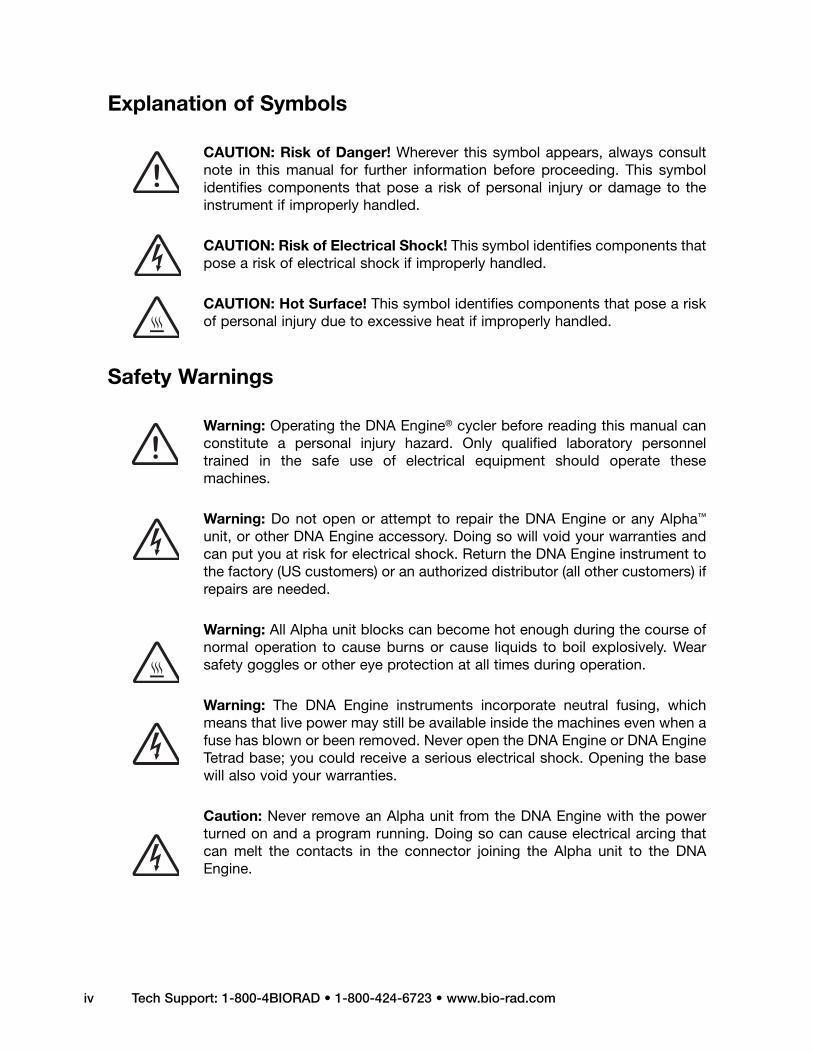
Explanation of Symbols
CAUTION: Risk of Danger! Wherever this symbol appears, always consultnote in this manual for further information before proceeding. This symbolidentifies components that pose a risk of personal injury or damage to theinstrument if improperly handled.
CAUTION: Risk of Electrical Shock! This symbol identifies components thatpose a risk of electrical shock if improperly handled.
CAUTION: Hot Surface! This symbol identifies components that pose a riskof personal injury due to excessive heat if improperly handled.
Safety Warnings
Warning: Operating the DNA Engine® cycler before reading this manual canconstitute a personal injury hazard. Only qualified laboratory personneltrained in the safe use of electrical equipment should operate thesemachines.
Warning: Do not open or attempt to repair the DNA Engine or any Alpha™
unit, or other DNA Engine accessory. Doing so will void your warranties andcan put you at risk for electrical shock. Return the DNA Engine instrument tothe factory (US customers) or an authorized distributor (all other customers) ifrepairs are needed.
Warning: All Alpha unit blocks can become hot enough during the course ofnormal operation to cause burns or cause liquids to boil explosively. Wearsafety goggles or other eye protection at all times during operation.
Warning: The DNA Engine instruments incorporate neutral fusing, whichmeans that live power may still be available inside the machines even when afuse has blown or been removed. Never open the DNA Engine or DNA EngineTetrad base; you could receive a serious electrical shock. Opening the basewill also void your warranties.
Caution: Never remove an Alpha unit from the DNA Engine with the powerturned on and a program running. Doing so can cause electrical arcing thatcan melt the contacts in the connector joining the Alpha unit to the DNAEngine.

Safe Use Guidelines
The DNA Engine instruments are designed to be safe to operate under the followingconditions:
• Indoor use• Altitude up to 2000 m• Ambient temperature 5–31°C• Maximum relative humidity 90%, noncondensing• Transient overvoltage per Installation Category II, IEC 664• Pollution degree 2, in accordance with IEC 664
Electromagnetic Interference
These devices comply with Part 15 of the FCC Rules. Operation is subject to the followingtwo conditions: (1) these devices may not cause harmful interference, and (2) these devicesmust accept any interference received, including interference that may cause undesiredoperation.
These devices have been tested and found to comply with the EMC standards for emis-sions and susceptibility established by the European Union at time of manufacture.
This digital apparatus does not exceed the Class A limits for radio noise emissions from dig-ital apparatus set out in the Radio Interference Regulations of the Canadian Department ofCommunications.
LE PRESENT APPAREIL NUMERIQUE N’EMET PAS DE BRUITS RADIOELECTRIQUESDEPASSANT LES LIMITES APPLICABLES AUX APPAREILS NUMERIQUES DE CLASS APRESCRITES DANS LE REGLEMENT SUR LE BROUILLAGE RADIOELECTRIQUEEDICTE PAR LE MINISTERE DES COMMUNICATIONS DU CANADA.
FCC Warning
Warning: Changes or modifications to these units not expressly approved by the partyresponsible for compliance could void the user’s authority to operate the equipment.
This equipment qualifies as an “Exempted device” under Section 15.103(c) of the FCC Rules.Nonetheless, the design has been verified to comply within limits for Class “A” digital device.
Note: This equipment has been tested and found to comply with the limits for a Class Adigital device, pursuant to Part 15 of the FCC Rules. These limits are designed to providereasonable protection against harmful interference when the equipment is operated in acommercial environment. This equipment generates, uses, and can radiate radiofrequencyenergy and, if not installed and used in accordance with the instruction manual, may causeharmful interference to radio communications. Operation of this equipment in a residentialarea is likely to cause harmful interference in which case the user will be required to correctthe interference at his own expense.
Tech Support: 1-800-4BIORAD • 1-800-424-6723• www.bio-rad.com v

vi Tech Support: 1-800-4BIORAD • 1-800-424-6723 • www.bio-rad.com
Documentation Conventions
Typographic Conventions
The names of keyboard keys are set in double angle brackets:
Example «Proceed»
Items in programming menus are italicized:
Example Select Edit from the Main Menu.
Graphic Conventions
The programming screens displayed in the LCD window are represented by a boxcontaining four lines of text:
Example
Terminology
A programming option is termed “selected” when the cursor is positioned in front of it.Use the «Select» keys (see fig. 2-2) to move the cursor. In some screens selected itemsare also displayed in all-capital letters.
Run: 2-STEP
1= 92.0 for 0:05
Cycle: 1
Calc: 65.0

1-1
Introduction1Meet the DNA Engine Thermal Cycler . . . . . . . . . . . . . . . . . . . . . . . . . . . . . . . . . . . . . .1-2
Using This Manual . . . . . . . . . . . . . . . . . . . . . . . . . . . . . . . . . . . . . . . . . . . . . . . . . . . . . .1-2
Important Safety Information . . . . . . . . . . . . . . . . . . . . . . . . . . . . . . . . . . . . . . . . . . . . . .1-3

DNA Engine Operations Manual
1-2 Tech Support: 1-800-4BIORAD • 1-800-424-6723 • www.bio-rad.com
Meet the DNA Engine® Thermal Cycler
Thank you for purchasing a Bio-Rad PTC-0200 DNA Engine thermal cycler. Designedby a team of molecular biologists and engineers, the DNA Engine will meet yourneeds for a versatile, easy-to-use, reliable, and compact programmable thermalcycler.
• Interchangeable sample blocks—the Alpha™ unit family— that accommodatemany types of tubes, microplates, and slides
• Hot Bonnet® heated lid (or its remote-controlled version, the motorized MotoAlpha™ Moto Alpha unit) for oil-free cycling
• Intuitive software with easy-to-read interface for quick and painless programming,editing, file management, password protection, and much more
• Choice of calculated sample temperature control for highest speed and accuracy, orblock control for compatibility with protocols designed for a variety of instrument types
• Space-saving design for easy setup and transportation
• Instant Incubate feature for continuous-temperature incubations
• Networking of up to 15 machines, for convenient remote operation and documentationof runs
• Customizable factory-installed protocols
Using This Manual
This manual contains all the information you need to operate your DNA Engine safelyand productively:
• Chapter 2 acquaints you with the physical characteristics of the DNA Engine.
• Chapters 3–5 present the basics of installing and operating the DNA Engine.
• Chapters 6 and 7 describe programming the DNA Engine.
• Chapter 8 outlines the utilities available for the DNA Engine.
• Chapter 9 describes how to network and remotely operate the DNA Engine.
• Chapter 10 explains the proper maintenance of the DNA Engine.
• Chapter 11 offers troubleshooting information for the DNA Engine.

Introduction
Tech Support: 1-800-4BIORAD • 1-800-424-6723 • www.bio-rad.com 1-3
Important Safety Information
Safe operation of the DNA Engine begins with a complete understanding of how themachine works. Please read this entire manual before attempting to operate the DNAEngine. Do not allow anyone who has not read this manual to operate the machine.
The DNA Engine can generate enough heat to inflict serious burns and can deliverstrong electrical shocks if not used according to the instructions in this manual. Pleaseread the safety warnings and guidelines at the front of this manual, and exercise all pre-cautions outlined in them.


2-1
Layout and Specifications 2Front View . . . . . . . . . . . . . . . . . . . . . . . . . . . . . . . . . . . . . . . . . . . . . . . . . . . . . . . . . . . . .2-2
Control Panel . . . . . . . . . . . . . . . . . . . . . . . . . . . . . . . . . . . . . . . . . . . . . . . . . . . . . . . . . . .2-2
Back View . . . . . . . . . . . . . . . . . . . . . . . . . . . . . . . . . . . . . . . . . . . . . . . . . . . . . . . . . . . . .2-3
Bottom View . . . . . . . . . . . . . . . . . . . . . . . . . . . . . . . . . . . . . . . . . . . . . . . . . . . . . . . . . . .2-3
Alpha Units . . . . . . . . . . . . . . . . . . . . . . . . . . . . . . . . . . . . . . . . . . . . . . . . . . . . . . . . . . . .2-4
Single-Block Models . . . . . . . . . . . . . . . . . . . . . . . . . . . . . . . . . . . . . . . . . . . . . . . .2-4
Dual-Block Models . . . . . . . . . . . . . . . . . . . . . . . . . . . . . . . . . . . . . . . . . . . . . . . . .2-4
Slide Block . . . . . . . . . . . . . . . . . . . . . . . . . . . . . . . . . . . . . . . . . . . . . . . . . . . . . . .2-4
Moto Alpha Unit . . . . . . . . . . . . . . . . . . . . . . . . . . . . . . . . . . . . . . . . . . . . . . . . . . .2-4
Specifications . . . . . . . . . . . . . . . . . . . . . . . . . . . . . . . . . . . . . . . . . . . . . . . . . . . . . . . . . .2-5
Gradient Specifications . . . . . . . . . . . . . . . . . . . . . . . . . . . . . . . . . . . . . . . . . . . . . . . . . .2-6

Front View
(Figure 2-1)
Control Panel
(Figure 2-2)
DNA Engine Operations Manual
2-2 Tech Support: 1-800-4BIORAD • 1-800-424-6723 • www.bio-rad.com
Alpha™ unit, lid closedThumbwheel
Air intake vents
Control panel
Air exhaust vents(also on other side)
Block status lights
Instant incubation key
Power light
Block key
LCD window
Left and rightselection keys
Proceed key
Cancel key

Layout and Specifications
Tech Support: 1-800-4BIORAD • 1-800-424-6723 • www.bio-rad.com 2-3
Back View
(Figure 2-3)
Bottom View
(Figure 2-4)
Air exhaust vents(also on other side)
Alpha unit
Air intake vents
Alpha unit handle
Power cord jack
RS-232 port IEEE-488 port
Parallel printer port
Back Front
Air intake vents

Alpha Units
Single-Block Models
60V Alpha unit: Holds 60 x 0.5 ml tubes
96V Alpha unit: Holds 96 x 0.2 ml tubes orone 96-well microplate
384 Alpha unit: Holds one 384-wellmicroplate or one 96-wellmicroplate
Dual-Block Models
30/30 Dual Alpha™ Holds 2 x 30 x 0.5unit: ml tubes
30/48 Dual Alpha unit: Holds 1 x 30 x 0.5 mltubes and 1 x 48 x0.2 ml tubes
48/48 Dual Alpha unit: Holds 2 x 48 x 0.2 mltubes or half plates
Slide Block
Slide Chambers™ Alpha unit: Holds 2 x 16standard slides
Moto Alpha™ unit
Permits remote control of Alpha unit lid opening;available in 96-well, 384-well, and flat-block formats.
DNA Engine Operations Manual
2-4 Tech Support: 1-800-4BIORAD • 1-800-424-6723 • www.bio-rad.com

Layout and Specifications
Tech Support: 1-800-4BIORAD • 1-800-424-6723 • www.bio-rad.com 2-5
Specifications
Thermal range: –5° to 105°C, but no more than 30°C below ambienttemperature (4° to 100°C for the Slide Chambers Alpha unit)
Thermal accuracy: ±0.3°C of programmed target at 90°C, NIST-traceable
Thermal uniformity: ±0.4°C well-to-well within 30 seconds of arrival at 90°C(for most Alpha units; see specifications for individualAlpha units)
Ramping speed: Up to 3°C/sec for all single- and dual-block Alpha units;up to 1.2°C/sec for the Slide Chambers Alpha unit.
Sample capacity: Varies with installed Alpha unit
Line voltage: DNA Engine® cycler: 100–240 VAC rms (no adjustmentneeded among voltages within these ranges)
Frequency: 50–60 Hz single phase
Power: DNA Engine cycler: 850 W maximum
Fuses: Two 6.3 A, 250 V, 5 x 20 mm
Displays: One 20 x 4 LCD alphanumeric display
Ports: One 25-pin 8-bit parallel interface printer portOne 9-pin RS-232 serial port for printer or remote useOne IEEE-488 bidirectional general purpose interface bus
Memory: 400 typical programs in up to 12 individual folders

DNA Engine Operations Manual
2-6 Tech Support: 1-800-4BIORAD • 1-800-424-6723 • www.bio-rad.com
Gradient Specifications (96V Alpha module only)
Accuracy: +0.3°C of programmed target at end columns, 30seconds after the timer starts for the gradient step,NIST–traceable
Column uniformity: +0.4°C, well–to–well within column, within 30 seconds of reaching target temperature
Gradient calculator accuracy: +0.4°C of actual well temperature
Lowest programmable temp: 30°C
Highest programmable temp: 105°C

3-1
Installation3Packing Checklist . . . . . . . . . . . . . . . . . . . . . . . . . . . . . . . . . . . . . . . . . . . . . . . . . . . . . . .3-2
Setting Up the DNA Engine Cycler . . . . . . . . . . . . . . . . . . . . . . . . . . . . . . . . . . . . . . . . .3-2
Environmental Requirements . . . . . . . . . . . . . . . . . . . . . . . . . . . . . . . . . . . . . . . . . . . . . .3-2
Power Supply Requirements . . . . . . . . . . . . . . . . . . . . . . . . . . . . . . . . . . . . . . . . . . . . . .3-3
Air Supply Requirements . . . . . . . . . . . . . . . . . . . . . . . . . . . . . . . . . . . . . . . . . . . . . . . . .3-3
Ensuring an Adequate Air Supply . . . . . . . . . . . . . . . . . . . . . . . . . . . . . . . . . . . . . .3-3
Ensuring That Air Is Cool Enough . . . . . . . . . . . . . . . . . . . . . . . . . . . . . . . . . . . . . .3-4
Requirements for Robotics Installations . . . . . . . . . . . . . . . . . . . . . . . . . . . . . . . . . . . .3-4
DNA Engine Operations Manual
3-2 Tech Support: 1-800-4BIORAD • 1-800-424-6723 • www.bio-rad.com
Packing Checklist
After unpacking the DNA Engine® cycler, check to see that you have received the fol-lowing:
• One DNA Engine base
• One Alpha™ unit (more if additional units were ordered)
• Two spare fuses
• One power cord
• DNA Engine Peltier Thermal Cycler, Operations Manual (this document)
If any of these components are missing or damaged, contact Bio-Rad or the authorized dis-tributor from whom you purchased the DNA Engine cycler to obtain a replacement. Pleasesave the original packing materials in case you need to return the DNA Engine cycler forservice. See appendix A for warranty information.
Setting Up the DNA Engine Cycler
The DNA Engine cycler requires only minimal assembly: plugging in the power cord andinserting an Alpha unit. Insert the power cord plug into its jack at the back of the machine(see fig. 2-3 for location of jack), then plug the cord into an electrical outlet. With themachine turned off, insert an Alpha unit (see “Installing an Alpha Unit,” chapter 4).
Caution: Do not insert or remove an Alpha unit with the DNA Engine cyclerturned on; electrical arcing can result. Read the safety warning atthe front of this manual regarding electrical safety when inserting orremoving an Alpha unit.
Environmental Requirements
Ensure that the area where the DNA Engine cycler is installed meets the followingconditions, for reasons of safety and performance:
• Nonexplosive environment
• Normal air pressure (altitude below 2000 m)
• Ambient temperature 5–31°C
• Relative humidity up to 90%
• Unobstructed access to air that is 31°C or cooler (see below)

Installation
Tech Support: 1-800-4BIORAD • 1-800-424-6723 • www.bio-rad.com 3-3
• Protection from excessive heat and accidental spills (Do not place the DNA Enginecycler near such heat sources as radiators, and protect it from danger of havingwater or other fluids splashed on it, which can cause shorting in its electrical cir-cuits.)
Power Supply Requirements
The DNA Engine cycler requires 100–240 VAC, 50–60 Hz, and a grounded outlet. The DNAEngine cycler can use current in the specified range without adjustment, so there is novoltage-setting switch.
Power cords for outlets other than the US 120V outlet may be purchased from computerstores, since they are also used for most desktop computers and printers and meetinternational standard IEC-320. The power cord must be rated to carry at least 10 A at125 V or 250 V, depending on the voltage available in your nation. The quality of thepower cord can be further ensured by making certain it is inscribed with the trademarkof UL, CSA, TUV, VDE, or another national testing agency.
Note: Do not cut the supplied 120 V power cord and attach a different connector.Use a one-piece molded connector of the type specified above.
Air Supply Requirements
The DNA Engine cycler requires a constant supply of air that is 31°C or cooler in orderto remove heat from the Alpha unit’s heat sink. Air is taken in from vents at the front,back, and bottom of the machine and exhausted from vents on both sides (see figs. 2-1, 2-3, and 2-4). If the air supply is inadequate or too hot, the machine can overheat,causing performance problems, software error messages (particularly “HS Overheating”and “Slow Block Cycling”), and even automatic shutdowns. Special attention should bepaid to airflow and air temperature in robotics installations of DNA Engine cyclers.
Ensuring an Adequate Air Supply
• Do not block the air intake vents.
Position the DNA Engine cycler at least 10 cm from vertical surfaces and other thermalcyclers (greater distances may be required; see below). Do not put loose papers underthe machine; they can be sucked into the air intake vents on the bottom of the machine.
• Do not allow dust or debris to collect in the air intake vents.
The bottom air vents are particularly liable to collect dust and debris, sometimescompletely clogging up. Check for dust and debris every few months, and clean theintake vents as needed. Remove light collections of dust with a soft-bristle brush or dampcloth. Severe collections of dust and debris should be vacuumed out. Turn the machineoff prior to cleaning or vacuuming air vents.

DNA Engine Operations Manual
3-4 Tech Support: 1-800-4BIORAD • 1-800-424-6723 • www.bio-rad.com
Ensuring That Air Is Cool Enough
• Do not position two or more DNA Engine cyclers (or other thermal cyclers) so thatthe hot exhaust air of one blows directly into the air intake vents of another.
• Make sure the DNA Engine cycler receives air that is 31°C or cooler by measuringthe temperature of air entering the machine through its air intake vents.
Place the DNA Engine cycler where you plan to use it, and turn it on. Try to reproducewhat will be typical operating conditions for the machine in that location, particularlyany heat-producing factors (e.g., nearby equipment running, window blinds open,lights on). Run a typical protocol (e.g., 2-Step) for 30 minutes to warm up the DNAEngine cycler, then measure the air temperature at the back air intake vents. If morethan one machine is involved, measure the air temperature for each.
If the air intake temperature of any machine is warmer than 31°C, use table 3-1 to troubleshoot the problem. Some experimentation may be required to determine thebest solution when more than one cause is involved. After taking steps to solve theproblem, verify that the temperature of the air entering the air intake vents has beenlowered, using the procedure outlined above.
Requirements for Robotics Installations
Robotics installations require special attention to airflow and air temperature. Typically inthese installations, DNA Engine cyclers and other thermal cyclers are crowded into asmall area, along with other heat-generating equipment. Overheating can quickly occurwhen many of these machines are operating at once, unless preventive measures aretaken.
Follow the procedures described above to ensure adequate airflow and an air intaketemperature of 31°C or cooler. Air intake temperature must be verified by measurement.
Do not use oil to thermally couple sample vessels to the blocks of machines in a roboticsinstallation. Oil makes plates difficult to remove.
Table 3-1 Troubleshooting Air Supply Problems
Cause Possible Remedies
Air circulation is poor. Provide more space around machine or adjacent room ventilation.
Ambient air temperature ishigh.
Adjust air conditioning to lower ambient air temperature.
Machine is in warm part ofroom.
Move machine away from, or protect machine from, such heatsources as radiators, heaters, other equipment, or bright sunlight.
Machines are crowded.Arrange machines so that warm exhaust air does not enter intakevents.

4-1
Operation4Turning the DNA Engine Cycler On . . . . . . . . . . . . . . . . . . . . . . . . . . . . . . . . . . . . . . . . .4-2
Understanding the Main Menu . . . . . . . . . . . . . . . . . . . . . . . . . . . . . . . . . . . . . . . . . . . .4-2
Using the Control Panel . . . . . . . . . . . . . . . . . . . . . . . . . . . . . . . . . . . . . . . . . . . . . . . . .4-3
Operation Keys . . . . . . . . . . . . . . . . . . . . . . . . . . . . . . . . . . . . . . . . . . . . . . . . . . . .4-3
Status Indicator Lights . . . . . . . . . . . . . . . . . . . . . . . . . . . . . . . . . . . . . . . . . . . . . .4-3
Using the Data Ports . . . . . . . . . . . . . . . . . . . . . . . . . . . . . . . . . . . . . . . . . . . . . . . . . . . .4-3
Operating Alpha Units . . . . . . . . . . . . . . . . . . . . . . . . . . . . . . . . . . . . . . . . . . . . . . . . . . .4-4
Installing an Alpha Unit . . . . . . . . . . . . . . . . . . . . . . . . . . . . . . . . . . . . . . . . . . . . . .4-4
Removing an Alpha Unit . . . . . . . . . . . . . . . . . . . . . . . . . . . . . . . . . . . . . . . . . . . . .4-5
Opening an Alpha Unit . . . . . . . . . . . . . . . . . . . . . . . . . . . . . . . . . . . . . . . . . . . . . .4-5
Closing an Alpha Unit . . . . . . . . . . . . . . . . . . . . . . . . . . . . . . . . . . . . . . . . . . . . . . .4-5
Selecting the Correct Sample Vessel . . . . . . . . . . . . . . . . . . . . . . . . . . . . . . . . . . . . . . .4-6
0.5ml Tubes . . . . . . . . . . . . . . . . . . . . . . . . . . . . . . . . . . . . . . . . . . . . . . . . . . . . . . .4-6
0.2ml Tubes . . . . . . . . . . . . . . . . . . . . . . . . . . . . . . . . . . . . . . . . . . . . . . . . . . . . . . .4-6
Microplates . . . . . . . . . . . . . . . . . . . . . . . . . . . . . . . . . . . . . . . . . . . . . . . . . . . . . . .4-6
Thin-Walled Vs. Thick-Walled Tubes . . . . . . . . . . . . . . . . . . . . . . . . . . . . . . . . . . . .4-6
Sealing Sample Vessels . . . . . . . . . . . . . . . . . . . . . . . . . . . . . . . . . . . . . . . . . . . . . . . . . .4-7
Sealing with Oil or Wax . . . . . . . . . . . . . . . . . . . . . . . . . . . . . . . . . . . . . . . . . . . . . .4-7
Sealing with the Hot Bonnet Lid . . . . . . . . . . . . . . . . . . . . . . . . . . . . . . . . . . . . . . .4-7
Adjusting the Hot Bonnet Lid’s Pressure . . . . . . . . . . . . . . . . . . . . . . . . . . . . . . . .4-8
Loading Sample Vessels into the Block . . . . . . . . . . . . . . . . . . . . . . . . . . . . . . . . . . . . .4-9
Using Oil to Thermally Couple Sample Vessels to the Block . . . . . . . . . . . . . . . .4-10
Appendix 4-A: Tube, Microplate, and Sealing System Selection Chart . . . . . . . . . . .4-11
Appendix 4-B: Safety Warning Regarding Use of 35S Nucleotides . . . . . . . . . . . . . .4-12

DNA Engine Operations Manual
4-2 Tech Support: 1-800-4BIORAD • 1-800-424-6723 • www.bio-rad.com
Turning the DNA Engine® Cycler On
Move the power switch to “1” (the “On” position). The fan will turn on and the power lighton the keyboard will glow red. In most cases a self-test of the heat pumps will beginrunning (see note below). Its progress is tracked on a screen in the LCD window:
This screen disappears in 1 minute. If a problem is detected, the display shows an errormessage.
Note: If the Alpha™ unit’s block or heat sink is not at ambient temperature (typicallybecause the Alpha unit was recently in use), the machine will skip the self-test.
If the self-test does not detect any problems, the Main Menu is displayed:
The DNA Engine cycler is now ready to execute programs.
Understanding the Main Menu
The Main Menu is the common access point to all programming and machine configurationscreens.
• Run: Executes a program.
• Enter: Allows new programs to be entered.
• List: Accesses utilities that display or print a program’s steps.
• Edit: Allows modification of stored programs.
• Files: Accesses file management utilities.
• Setup: Accesses machine and networking configuration screens.
PTC-200:
Self testing.
PTC-200:_RUN EnterList EditFiles Setup
Operation
Tech Support: 1-800-4BIORAD • 1-800-424-6723 • www.bio-rad.com 4-3
Using the Control Panel
The control panel (see fig. 2-2) includes operation keys, status indicator lights, an LCDwindow for displaying programming and machine status text, and a numeric keypadfor entering values into programs.
Operation Keys
• Select keys (left and right arrows): Move the cursor one space or option to the left orright in the LCD window; during a protocol run, display time and cycle information.
• Proceed: Accepts a selected menu or screen option; during a protocol run, advancesthe program to its next step.
• Cancel: Terminates a running protocol; during program creation or editing, cancelsthe last entry.
• Stop: Terminates a running protocol.
• Pause: Pauses a protocol during execution; accesses Japanese Katakana syllabary.
• Instant Incubate: Initiates a program that sets up the DNA Engine cycler as asimple incubator.
• Block: Selects a different block when using a Dual Alpha™ unit; switches betweenblock screens and the Main Menu in the LCD window during a protocol run.
Status Indicator Lights
• Power light: Glows red when the DNA Engine cycler is powered up.
• Block Status lights: Indicate which blocks are in use; glow red when blocks areheating and green when blocks are cooling.
Using the Data Ports
The DNA Engine cycler has three data ports located at the rear of the machine: an RS-232 port, an IEEE-488 port, and a parallel (printer) port. See chapters 8 and 9 forinformation on using these ports to network machines, connect them to a computer, orprint data.

DNA Engine Operations Manual
4-4 Tech Support: 1-800-4BIORAD • 1-800-424-6723 • www.bio-rad.com
Operating Alpha Units
Note: Operation of the Slide Chambers™ Alpha unit will not be discussed, owing tothe many differences between this type of Alpha unit and the others. Please see theSlide Chambers Operations Manual for operating instructions.
Note: Moto Alpha™ units are installed and removed as described below. See theMoto Alpha Unit Operations Manual for instructions on opening and closing MotoAlpha units.
Installing an Alpha Unit
1. Turn the DNA Engine cycler off (see the Caution on p. 4-5).
2. Hold the Alpha unit at its front and back edges.
3. Lower the Alpha unit into the DNA Engine base, leaving at least 3cm between thefront edge of the Alpha unit and the front of the base.
4. Raise the handle at the back of the Alpha unit, and slide the block forward as faras it will go (fig. 4-1A).
5. Push the handle down until it is completely vertical (fig. 4-1B); firm pressure maybe required. A definite click signals that the Alpha unit’s connectors have matedwith the DNA Engine cycler’s connectors.
When the handle is in the down position, the Alpha unit is locked into place.
Figure 4-1 Installing an Alpha unit.
A B

Operation
Tech Support: 1-800-4BIORAD • 1-800-424-6723 • www.bio-rad.com 4-5
Removing an Alpha Unit
1. Turn the DNA Engine cycler off (see the Caution below).
2. Pull upward on the handle. When the lock releases, you will hear a click, and theAlpha unit will slide a little toward the back of the DNA Engine cycler. The elec-trical connectors of the Alpha unit and the DNA Engine cycler are nowdisengaged, so there is no danger of electrical shock.
3. Slide the Alpha unit toward the rear of the DNA Engine cycler about 3 cm.
4. Grasp the front and back edges of the Alpha unit, and lift it out of the machine.
Caution: Do not insert or remove an Alpha unit with the DNA Enginecycler turned on; electrical arcing can result. Read the safetywarning at the front of this manual regarding electrical safetywhen inserting or removing an Alpha unit.
Opening an Alpha Unit
Grip the front edge of the top lever of the Hot Bonnet® lid as shown in figure 4-2A,and pull upward firmly. The top lever will pop open to reveal the entire thumbwheel(fig. 4-2B). Continue pulling upward to open the Hot Bonnet lid. The Hot Bonnet lidwill tip backward, revealing the entire block.
Caution: Do not pull on the thumbwheel to open the unit. This candamage the Hot Bonnet lid’s closing mechanism.
Closing an Alpha Unit
Press down on the top lever. The lever will close down over the thumbwheel as theHot Bonnet lid closes down over the sample block. A click signifies that theHot Bonnet lid’s latch has engaged.
Figure 4-2 Opening an Alpha unit.
A B

DNA Engine Operations Manual
4-6 Tech Support: 1-800-4BIORAD • 1-800-424-6723 • www.bio-rad.com
Selecting the Correct Sample Vessel
The DNA Engine cycler’s wide variety of interchangeable Alpha units affords you greatscope in choosing sample vessels. Keep in mind that differences in tube and plate com-position and wall thickness among the many brands available can affect reactionperformance. Protocols may require some adjustment to ensure optimum performancewhen using a new vessel type. Bio-Rad offers a full range of tubes and microplates, man-ufactured to the specifications of each type of Alpha unit to ensure a precise fit. Seechapter appendix 4-A for a complete list.
0.5 ml Tubes
Make sure thick-walled 0.5 ml tubes fit the wells snugly. Since these tubes were originallydesigned for centrifuges, some brands may not fit tightly in thermal cycler wells. Thin-walled0.5 ml tubes were specifically designed for thermal cycling, and the higher quality brandsprovide a good and consistent fit. Bio-Rad provides thin- and thick-walled 0.5 ml tubesdesigned for precise block fit.
0.2 ml Tubes
All types of thin-walled 0.2 ml tubes may be used. Bio-Rad sells high-quality 0.2 mltubes in a number of styles, including individual tubes and strips.
Microplates
A variety of 96-well polycarbonate or polypropylene microplates can be used in 96-wellAlpha units as long as they fit the wells snugly. Polypropylene microplates are usuallypreferred because they exhibit very low protein binding and, unlike polycarbonatemicroplates, do not lose water vapor through the vessel walls. This allows smallersample volumes to be used — as little as 5–10 µl. Polypropylene microplates and com-patible sealing systems are available from Bio-Rad. (See “Sealing Sample Vessels” onthe next page for a description of available sealing systems from Bio-Rad.)
Thin-Walled Vs. Thick-Walled Tubes
The thickness of sample tubes directly affects the speed of sample heating and thusthe amount of time required for incubations. Thick-walled tubes delay sample heating,since heat transfers more slowly through the tubes’ walls. For the earliest types ofthermal cyclers this delay mattered little. These machines’ ramping rates were so slow(below 1°C/sec) that there was plenty of time for heat to transfer through the tube wallto the sample, during a given incubation.
Modern thermal cyclers have much faster ramping rates (up to 2–3°C/sec), so the fasterheat transfer provided by thin-walled tubes allows protocols to be significantly short-ened. On average, about 30 seconds can be saved per cycle by using thin-walledtubes, for an overall savings of 15 minutes in a 30-cycle run.

Operation
Tech Support: 1-800-4BIORAD • 1-800-424-6723 • www.bio-rad.com 4-7
Sealing Sample Vessels
To avoid changing the concentration of reactants, steps must be taken to prevent theevaporation of water from reaction mixtures during thermal cycling. Only a layer of oilor wax will completely prevent evaporation from the surface of the reaction fluid.However, an adequate degree of protection can be achieved by sealing vessels withcaps, film, adhesive seals, or mats, then cycling the samples using the heated lid toprevent condensation.
Sealing with Oil or Wax
Mineral oil, silicone oil, paraffin wax, or Chill-out™ liquid wax may be used to seal samples.Use only a small amount of oil or wax; 1–3 drops (15–50µl) are usually sufficient. (Includethis volume in the total volume when setting up a calculated-control protocol; see“Choosing a Temperature Control Mode” in Chapter 5.) Use the same amount of oil orwax in all sample vessels to ensure a uniform thermal profile.
Most paraffin waxes solidify at room temperature. The wax can then be pierced with amicropipette and the samples drawn off from below the wax. Silicone oil and mineral oilcan be poured off or aspirated from tubes if the samples are first frozen (–15° to –20°C).The samples are usually pure enough for analysis without an extraction.
Chill-out liquid wax (available from Bio-Rad) is an easy-to-use alternative to oil. This puri-fied paraffinic oil solidifies at 10°C and is liquid at room temperature. By programming ahold at low temperature, the wax can be solidified at the end of a run. A pipette tip canthen be used to pierce the wax in the tubes and remove the samples. The wax is availablein a clear, optical-assay grade or dyed red to assist in monitoring its use. The red dye hasno adverse effects on fluorescent gel analysis of reaction products.
Sealing with the Hot Bonnet Lid
The Hot Bonnet lid’s heated inner surface maintains the air in the upper part ofsample vessels at a higher temperature than the reaction mixture. This prevents con-densation of evaporated water vapor onto the vessel walls and lid, so that solutionconcentrations are unchanged by thermal cycling. The Hot Bonnet lid also exertspressure on the tops of vessels loaded into the block, helping to maintain a vapor-tight seal and to firmly seat tubes or the plate in the block.
Caps, film, adhesive seals, or mats must be used along with the Hot Bonnet lid to preventevaporative losses.
Note: When tubes are cooled to below-ambient temperatures, a ring of condensationmay form in tubes above the liquid level but below the top of the sample block. Thisis not a cause for concern since it occurs only at the final cool-down step, whenthermal cycling is complete.

DNA Engine Operations Manual
4-8 Tech Support: 1-800-4BIORAD • 1-800-424-6723 • www.bio-rad.com
Microseal® ‘A’ film offers a quick alternative to sealing microplates or arrays of tubestrips. This film is specially designed to seal tightly during cycling, yet release smoothlyto minimize the risk of aerosol formation and cross-contamination of samples.Microseal ‘A’ film is easily cut for use with fewer than 96 samples.
Microseal ‘B’ adhesive seals feature an aggressive adhesive, effective from –20°C to110°C, which allows secure sample storage or transport before and after cycling. Theclear polyester backing allows easy inspection of sample wells. Microseal ‘B’ clear,adhesive seals are ideal for thermal cycling in all polypropylene and polystyrenemicroplates.
Microseal ‘F’ aluminized foil acts as a barrier against evaporation from –20°C to 105°C.It is thin enough to pierce with a pipet tip for recovery of sample from individual wells.
96-well PCR plate sealing mats (223-9442) are an economical means to seal 96-wellmicroplates. An array of 96 dimples on the mat helps orient it on the microplate and pre-vents the mat from sticking to the heated lid. The mats may be cleaned with sodiumhypochlorite (bleach) for reuse, and they are autoclavable.
Microseal ‘P’/’P+’ pads are designed for use in applications such as cycle sequencing, inwhich several successive runs may be sealed with the same pad. Use ‘P’ pads with theoriginal version of Power Bonnet™ lids (ALP-1296 and ALP-1238) and use ‘P+’ pads withthe newer-design Moto Alpha™ units (ALP-2296, ALP- 2238, ALP-2200, and ALP-2201).
Adjusting the Hot Bonnet Lid’s Pressure
The pressure exerted by the inner lid of the Hot Bonnet lid must be manually adjustedto fit the sample vessels being used in a given reaction. Once set, the Hot Bonnet lidcan be opened and closed repeatedly without readjustment as long as neither thetube or microplate type nor the sealing method changes. Any change in vessel typeor sealing method requires readjustment of the Hot Bonnet lid.
Follow these steps to adjust the pressure exerted by the Hot Bonnet inner lid:
1. Make sure the block’s wells are clean. Even tiny amounts of extraneous materialcan interfere with the proper seating of a microplate or tubes, which would preventthe inner lid from exerting uniform pressure on the loaded microplate or tubes.
2. Open the Hot Bonnet lid. Turn the green thumbwheel all the way counterclock-wise to completely raise the inner lid.
3. Load either a microplate or at least eight individual tubes into the sample block. Theinner lid pivots around a central point, so it is important to distribute individual tubesevenly. Load at least four tubes in the center of the block and at least one tube ineach of the four corners of the block. If using a sealing film or mat, apply it to theloaded microplate according to the manufacturer’s directions.

Operation
Tech Support: 1-800-4BIORAD • 1-800-424-6723 • www.bio-rad.com 4-9
4. Close the Hot Bonnet lid by pressing down on the top lever. Turn the thumbwheelclockwise to lower the Hot Bonnet inner lid onto the loaded microplate/tubes. Thethumbwheel turns easily at first since the inner lid has not yet come into contactwith anything. Stop turning the thumbwheel when you feel increased resistance,which indicates that the inner lid has touched the microplate/tubes.
5. Open the Hot Bonnet lid. Turn the thumbwheel clockwise an extra half to three-quar-ters of a turn to set an appropriate lid pressure.
Caution: Do not turn the thumbwheel more than three-quarters of aturn. This can make it hard or impossible to close the lid andputs excessive strain on the latch holding the lid closed.
An extra half to three-quarters of a turn ensures the correct pressure for most types ofreaction vessels. Some empirical testing may be required to determine the optimumpressure required for certain vessels. Once this pressure has been determined, thethumbwheel position that delivers it may be marked with a colored marking pen orpiece of tape.
Note: As an aid in gauging how much the thumbwheel has been turned, mark it atthe quarter turn positions, or every sixth bump on the thumbwheel (there are 24 totalbumps).
6. Close the Hot Bonnet lid.
Loading Sample Vessels into the Block
When using a small number of tubes, they should all be placed in the center of the block,to ensure uniform thermal cycling of all samples. Also load at least one empty tube ineach corner of the block, to ensure that the Hot Bonnet lid exerts even pressure on thesample tubes (see “Adjusting the Hot Bonnet Lid Pressure,” above).
To ensure uniform heating and cooling of samples, sample vessels must be in completecontact with the block. Adequate contact is ensured by always doing the following:
• Ensure that the block is clean before loading samples. (See chapter 10 forcleaning instructions.)
• Firmly press individual tubes or the microplate into the block wells.

DNA Engine Operations Manual
4-10 Tech Support: 1-800-4BIORAD • 1-800-424-6723 • www.bio-rad.com
Using Oil to Thermally Couple Sample Vessels to the Block
With two exceptions (see below), Bio-Rad does not recommend using oil to thermallycouple sample vessels to the block, for the following reasons:
• Calculated-control protocols do not run accurately when oil is used.
• Oil traps dirt, which interferes with thermal contact between vessels and the block.
Caution: If you use oil in the block, use only mineral oil. Never use siliconeoil. It can damage the Alpha unit.
One exception to this recommendation involves the use of volatile radioactive 35Snucleotides. A small amount of oil in the block can help prevent escape of thesecompounds. See chapter appendix 4-B for important information regarding safe useof these compounds in polypropylene tubes and polypropylene and polycarbonatemicroplates. A second exception involves the use of thick-wall 0.5 ml tubes. Certainbrands of these tubes fit poorly in the block, in which case oil may somewhatimprove thermal contact. Whenever possible, use high-quality thin-wall tubesintended for thermal cycling. (See chapter appendix 4-A for a tube and plate selec-tion chart.)

Operation
Tech Support: 1-800-4BIORAD • 1-800-424-6723 • www.bio-rad.com 4-11
Appendix 4-A Tube, Microplate, and SealingSystem Selection Chart
Key
4 Reaction vessel fits block/sealing option fits reaction vessel without modification.# Reaction vessel/sealing option can be cut to fit.
* “Concord” microplates are made from polycarbonate plastic, which is prone to poorsealing and vapor leakage during stringent thermal cycling.
** Since plates may adhere tightly to the Microseal ‘P+’ pad, this seal is only recommendedfor use with the Moto Alpha™ motorized unit, which has the ability to hold the plate in the block.
Bio-Rad ThermalCycler Blocks
Reaction Vessels Sealing Options for Oil-Free Cycling
384 96(0.2ml)
48(0.2ml)
60/30(0.5ml)
Description Bio-RadCatalog #
Microseal‘A’ film
MSA-5001
Microseal‘B’ seal
MSB-1001
Microseal‘F’ foil
MSF-1001
Sealingmat
223-9442
Microseal‘P’ pad
MSP-1001
Microseal‘P+’ pad**MSP-1002
Stripcaps
TCS-series
Chill-outwax
CHO-series
4 Hard-Shell® skirted384-well microplates
HSP-series 4 4 4 4 4 4
4 Microseal® skirted384-well microplates
MSP-series 4 4 4 4 4
4 Hard-Shell skirted96-well microplates
HSP-series 4 4 4 4 4 4 4 4
4 Microseal skirted96-well microplates
MSP-series 4 4 4 4 4 4 4
4 # MultiplateTM unskirted96-well microplates
MLP-seriesMLL-series 4 4 4 4 4 4 4
4 4 Multiplate unskirted48-well microplates
MLP-series # # # # 4 4
4 4 Multiplate unskirted25-well microplates
MLP-2501 # # # # # 4
4 4 Multiplate unskirted24-well microplates
MLP-2401 # # # # 4 4
4 ConcordTM skirted96-well microplates*
CON-9601 4 4 4
4 4 0.2ml strip tubes8/strip & 12/strip
TBS-seriesTLS-series 4 4 4
4 4 0.2ml individualtubes
TFI-0201TWI-0201TBI-series
4 4 4
4 0.5ml individualtubes, w/caps
TBI-series 4

DNA Engine Operations Manual
4-12 Tech Support: 1-800-4BIORAD • 1-800-424-6723 • www.bio-rad.com
Appendix 4-B Safety Warning Regarding Use of35S Nucleotides
Some researchers have experienced a problem with radioactive contamination whenusing 35S in thermal cyclers. This problem has occurred with all types of reaction vessels.
The Problem
When 35S nucleotides are thermally cycled, a volatile chemical breakdown productforms, probably SO2. This product can escape the vessel and contaminate thesample block of a thermal cycler, and possibly the air in the laboratory.Contamination has been reported with microassay plates, 0.2 ml tubes, and 0.5 mltubes.
96-Well Polycarbonate Microplates
These microplates present the largest risk of contamination. Polycarbonate is some-what permeable both to water and the 35S breakdown product. This problem isexacerbated when polycarbonate plates are held at high temperatures for longperiods of time, or when the plates are sealed for oil-free thermal cycling.
0.2 ml Polypropylene Tubes and 96-Well Polypropylene Microplates
These tubes are manufactured with very thin walls to enhance thermal transfer. Thethin walls are somewhat fragile and can “craze” or develop small cracks when sub-ject to mechanical stress. Undamaged thin polypropylene tubes may also besomewhat permeable to the 35S breakdown product. Either way, there have beenreports of 35S passing through the walls of 0.2 ml tubes of several different brandsduring thermal cycling. No data are yet available on radioactive contamination withpolypropylene microplates.
0.5 ml Polypropylene Tubes
Contamination problems are rarer with this type of tube, but instances have beenreported.
The Solution
1. Substitute the low-energy beta emitter 33P in cycle sequencing. 33P nucleotidesare not subject to the same kind of chemical breakdown as 35S nucleotides, andthey have not been associated with volatile breakdown products.
2. If 35S must be used, three things will help control contamination: an oil overlayinside the tubes, mineral oil in the thermal cycler outside the tubes, and use ofthick-walled 0.5ml tubes. Always run 35S thermal cycling reactions in a fumehood, and be aware that vessels may be contaminated on the outside afterthermal cycling. Please be certain that you are using the appropriate detectionmethods and cleaning procedures for this isotope. Consult your radiation safetyofficer for his or her recommendations.

Operation
Tech Support: 1-800-4BIORAD • 1-800-424-6723 • www.bio-rad.com 4-13
If mild cleaning agents do not remove radioactivity, harsher cleaners may be used.Users have suggested the detergent PCC-54 (Pierce Chemical Co., Rockford, Illinois;Pierce Eurochemie B.V., Holland), Micro Cleaning Solution (Cole-Parmer, Niles, Illinois),and Dow Bathroom Cleaner (available in supermarkets).
Caution: Harsh cleaning agents are corrosive to aluminum and mustnever be used on bare aluminum blocks. Bio-Rad Alpha unitblocks are anodized, so they have a protective coating ofaluminum oxide. Still, harsh agents (such as those above)must be thoroughly rinsed away within a few minutes ofapplication, or the anodization will degrade.


5-1
Running Protocols5Running a Protocol . . . . . . . . . . . . . . . . . . . . . . . . . . . . . . . . . . . . . . . . . . . . . . . . . . . . . .5-2
Choosing a Stored Protocol to Run . . . . . . . . . . . . . . . . . . . . . . . . . . . . . . . . . . . .5-2
Choosing a Block to Run the Protocol On . . . . . . . . . . . . . . . . . . . . . . . . . . . . . .5-3
Setting Up the Temperature Control Method . . . . . . . . . . . . . . . . . . . . . . . . . . . . .5-3
Setting Up a Block-Control Protocol . . . . . . . . . . . . . . . . . . . . . . . . . . . . .5-3
Setting Up a Calculated-Control Protocol . . . . . . . . . . . . . . . . . . . . . . . . .5-4
Reading the Runtime Screen . . . . . . . . . . . . . . . . . . . . . . . . . . . . . . . . . . . . . . . . . . . . . .5-5
Switching Between the Runtime Screen and the Main Menu . . . . . . . . . . . . . . . .5-6
Reading the Protocol Completion Screen . . . . . . . . . . . . . . . . . . . . . . . . . . . . . . . . . . .5-6
Printing a Log for a Running Program . . . . . . . . . . . . . . . . . . . . . . . . . . . . . . . . . . . . . .5-6
Manually Stepping Through a Protocol . . . . . . . . . . . . . . . . . . . . . . . . . . . . . . . . . . . . .5-7
Pausing a Running Protocol . . . . . . . . . . . . . . . . . . . . . . . . . . . . . . . . . . . . . . . . . . . . . .5-7
Stopping a Running Protocol . . . . . . . . . . . . . . . . . . . . . . . . . . . . . . . . . . . . . . . . . . . . . .5-8
Resuming a Protocol after a Power Outage . . . . . . . . . . . . . . . . . . . . . . . . . . . . . . . . .5-8
Using the Instant Incubation Feature . . . . . . . . . . . . . . . . . . . . . . . . . . . . . . . . . . . . . . .5-9

DNA Engine Operations Manual
5-2 Tech Support: 1-800-4BIORAD • 1-800-424-6723 • www.bio-rad.com
Running a Protocol
Running a protocol on the DNA Engine® cycler involves three steps:
1. Choosing a stored protocol to run.
2. Choosing a block to run it on, if a Dual Alpha™ unit is installed.
3. Setting up the temperature control method.
Either a custom-designed protocol or one of the factory-installed resident protocolsmay be run. See appendix C for descriptions of the resident protocols, which may beedited to fit your needs (see chapter 7). All the factory-installed protocols are storedin a single folder, called the <MAIN> folder, at the time of shipping.
Choosing a Stored Protocol to Run
With the Main Menu displayed, select Run, then press «Proceed». One of two typesof screen will be displayed, depending on whether custom protocols have beenstored in the <MAIN> folder or in custom folders:
• If all protocols have been stored in the <MAIN> folder:
The first of three or more screens listing the protocols will be displayed. Custom protocolsare listed first, then the 14 factory-installed programs:
Use the «Select» keys to scroll through the listed protocols. Scroll past the last- or first-listedprotocol to see the next screen down or up. Select the desired protocol, then press«Proceed».
• If custom protocols have been stored in one or more custom folders:
One or more screens listing all the folders residing in the machine will be displayed:
Select the folder that contains the protocol, then press «Proceed». One or morescreens listing the protocols stored in the folder will be displayed. Use the «Select»keys to scroll through the listed protocols. Select the desired protocol, then press«Proceed».
Run: <MAIN>_CUSTOM1 CUSTOM2QUIKSTEP 2-STEP3-STEP EXTEND
Run:_<MAIN> <FOLDER><FOLDER2> <FOLDER3>
Running Protocols
Tech Support: 1-800-4BIORAD • 1-800-424-6723 • www.bio-rad.com 5-3
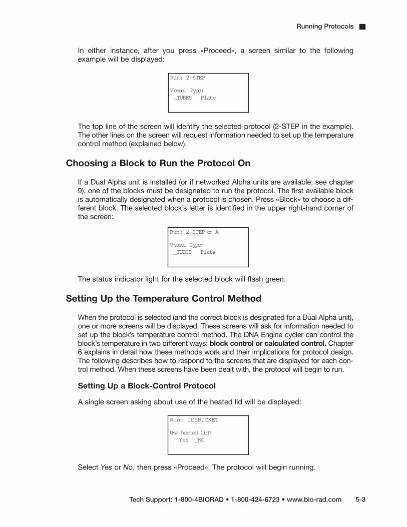
In either instance, after you press «Proceed», a screen similar to the followingexample will be displayed:
The top line of the screen will identify the selected protocol (2-STEP in the example).The other lines on the screen will request information needed to set up the temperaturecontrol method (explained below).
Choosing a Block to Run the Protocol On
If a Dual Alpha unit is installed (or if networked Alpha units are available; see chapter9), one of the blocks must be designated to run the protocol. The first available blockis automatically designated when a protocol is chosen. Press «Block» to choose a dif-ferent block. The selected block’s letter is identified in the upper right-hand corner ofthe screen:
The status indicator light for the selected block will flash green.
Setting Up the Temperature Control Method
When the protocol is selected (and the correct block is designated for a Dual Alpha unit),one or more screens will be displayed. These screens will ask for information needed toset up the block’s temperature control method. The DNA Engine cycler can control theblock’s temperature in two different ways: block control or calculated control. Chapter6 explains in detail how these methods work and their implications for protocol design.The following describes how to respond to the screens that are displayed for each con-trol method. When these screens have been dealt with, the protocol will begin to run.
Setting Up a Block-Control Protocol
A single screen asking about use of the heated lid will be displayed:
Select Yes or No, then press «Proceed». The protocol will begin running.
Run: 2-STEP
Vessel Type:_TUBES Plate
Run: 2-STEP on A
Vessel Type:_TUBES Plate
Run: ICEBUCKET
Use heated lid?Yes _NO

5-4 Tech Support: 1-800-4BIORAD • 1-800-424-6723 • www.bio-rad.com
Setting Up a Calculated-Control Protocol
Three screens will be presented:
• A screen asking for sample vessel information:
Select from the options shown (may include tubes, plates, and slides), then press«Proceed». Choose Plate for polycarbonate microplates and Tube for polypropylenetubes or polypropylene microplates. For blocks that hold only tubes, choose Thin orThick, depending on the type of tube loaded.
Note: See “Using Calculated Control” in the Slide Chambers Alpha Unit OperationsManual for information on specifying slide format.
• A screen asking for the sample reaction volume (last line in example below):
Use the keypad to enter a sample volume in microliters, then press «Proceed». Ifsample vessels are sealed with oil or wax, include the volume of the oil or wax in thetotal sample volume entered.
Note: Specify 10 µl for any volume less than 10 µl.
Note: Verify that your vessel sealing system is adequately tight before performing 5 µlreactions.
• A screen asking about use of the heated lid. Select Yes or No, then press«Proceed». The protocol will begin running.
Run: 2-STEP
Vessel Type:_TUBES Plate
Run: 2-STEP
Vessel Type: TUBESVolume (m l): 10
DNA Engine Operations Manual

Running Protocols
Tech Support: 1-800-4BIORAD • 1-800-424-6723 • www.bio-rad.com 5-5
Reading the Runtime Screen
During a protocol run, a runtime screen will be displayed:
The screen lists the protocol name (2-STEP in the example above), protocol step thatis running (1), cycle number (1), method of temperature control (Calc), and the blocktemperature for block-control protocols, and the calculated sample temperature forcalculated-control protocols (68.0°). When the step’s target temperature is reached,a timer begins running in the lower right-hand corner of the screen. The first digit isthe minutes elapsed; the two digits after the colon are the seconds elapsed.
For protocols using calculated control, press the left «Select» key to display theblock’s temperature on the third line of the screen:
This screen shows only as long as the left «Select» key is pressed. The runtimescreen returns when you stop pressing the key.
Press the right «Select» key to see a screen listing the cycle number (if a GoTo step isexecuting), time elapsed so far for the protocol run, and estimated remaining time leftin the run:
This screen is also displayed only as long as the key is pressed. The runtime screenreturns when you stop pressing the key.
Run: 2-STEP1= 92.0 for 0:05Block: 62.1
Calc: 68.0
Run: 2-STEP1= 92.0 for 0:05Cycle: 1
Calc: 68.0
Run: 2-STEPCycle: 1Total time: 0:20Est remain: 1:01:51

DNA Engine Operations Manual
5-6 Tech Support: 1-800-4BIORAD • 1-800-424-6723 • www.bio-rad.com
Switching Between the Runtime Screen and the Main Menu
Press «Block» to toggle between the runtime display and the Main Menu. This allowsyou to edit a stored program, enter a new one, print a program, run another protocolon a dual-block Alpha unit or networked DNA Engine cycler, or use the file utilities,while the protocol runs.
Reading the Protocol Completion Screen
When the protocol run finishes, a long beep sounds, and a notification screen is displayed:
Certain error messages may also be displayed in this screen (see chapter 11). Press«Proceed» to return to the Main Menu.
Printing a Log for a Running Protocol
If the DNA Engine cycler is connected to a printer, you can print a log for the run thatincludes:
• The DNA Engine cycler’s serial number and software version
• The protocol’s name
• The temperature control method for the protocol
• A list of the protocol’s steps
• The runtime thermal data
To print a runtime protocol log, first ensure that a printer is connected to the machine.See “Printing a Program,” chapter 8, for information about compatible printers.
Follow the instructions under “Choosing a Printer Port,” chapter 8, to prepare theDNA Engine cycler to communicate with your printer.
As long as a printer is connected to the machine, the following screen will appearwhenever a protocol is run:
Run: 2-STEPPROGRAM COMPLETE
Total time: 50:31
Run: 2-STEP
Printer output?_Yes No

Running Protocols
Tech Support: 1-800-4BIORAD • 1-800-424-6723 • www.bio-rad.com 5-7
To print the protocol as it runs, select Yes, then press «Proceed».
Note: If no printer is connected to the machine, the screen allowing you to selectprinter output is not displayed at all.
Manually Stepping Through a Protocol
Once a protocol is running, pressing «Proceed» gives you the option of immediatelyadvancing the protocol to the next programmed step, even if the machine is currentlyramping the block’s temperature (see chapter 6 for information on ramping). A confirmationscreen will be displayed:
Select Yes, then press «Proceed». The protocol will advance to its next step.
Pausing a Running Protocol
Press «Pause» to temporarily stop a running program. The timer in the lower right-handcorner of the runtime screen will be replaced by the word “Pause”:
The samples are held at the displayed temperature until either the «Pause» or the «Proceed»key is pressed, which causes the protocol run to resume.
A protocol cannot be paused before the target temperature for a given step has beenreached. If «Pause» is pressed before this point, the block continues heating or cooling untilthe target is reached, and then the protocol is paused.
Run: 2-STEP
Go on to next step?_YES No
Run: 2-STEP1= 92.0 for 0:05Cycle: 1Calc: 92 PAUSE

DNA Engine Operations Manual
5-8 Tech Support: 1-800-4BIORAD • 1-800-424-6723 • www.bio-rad.com
Stopping a Running Protocol
Press either «Stop» or «Cancel» to stop a running protocol. A cancellation confirmationscreen will be displayed:
Select Yes, then press «Proceed» to cancel the protocol. The total run time for theprotocol will be displayed:
Press «Proceed» to return to the Main Menu.
Note: Turning off the machine does not stop a running protocol. The DNA Engine cycler willassume the protocol was stopped by a power outage and will resume running the protocolwhen the machine is turned back on (see below).
Resuming a Protocol after a Power Outage
If a power failure occurs when a protocol is running, the DNA Engine cycler will hold the pro-tocol in memory for a minimum of 24 hours to a maximum of 7 days, depending onenvironmental conditions.
When power is restored, the protocol will begin running again at the point at which it wasstopped, and a notice about the power interruption will be displayed. The notice will identifythe step and the cycle that were running when the power failure occurred, and the block’stemperature at the time power was restored:
Press «Proceed» to remove this screen. The protocol’s runtime screen will immediately bedisplayed.
Run: 2-STEP
Stop 2-STEP?Yes _NO
Run: 2-STEPPROGRAM CANCELED
Total time: 1:15
Run: 2-STEPA/C POWER FAILED
Cycle 1 Step 1Recovered at 20.2

Running Protocols
Tech Support: 1-800-4BIORAD • 1-800-424-6723 • www.bio-rad.com 5-9
Using the Instant Incubation Feature
The DNA Engine cycler may be converted to a constant-temperature incubator bypressing «Instant Incubate». A screen allowing use of the heated lid will be displayed:
Use the «Select» keys to enable or disable the heated lid, then press «Proceed». A screenallowing entry of the incubation temperature will be displayed.
Use the keypad to enter any incubation temperature from –5.0° C to 105.0° C, thenpress «Proceed». The DNA Engine cycler will incubate the sample at the specified tem-perature until «Cancel» or «Stop» is pressed.
When the sample block reaches the incubation temperature, a timer begins running inthe lower right-hand corner of the screen. To stop and start the timer, press «Pause».
4 Tip: The Pause feature is useful if you need to temporarily remove samples that must beincubated for a precise period of time. Pausing the timer while samples are not in theblock allows you to track the exact duration of their incubation.
INCUBATE:
Use heated lid?Yes _No
INCUBATE:1= 20.0 for everUse heated lid?
Yes _No


6-1
Creating Programs6The Elements of a Program . . . . . . . . . . . . . . . . . . . . . . . . . . . . . . . . . . . . . . . . . . . . . . .6-2
Designing a New Program . . . . . . . . . . . . . . . . . . . . . . . . . . . . . . . . . . . . . . . . . . . . . . . .6-3
Translating a Protocol into a Program . . . . . . . . . . . . . . . . . . . . . . . . . . . . . . . . . .6-3
Using the GoTo Step to Write Short Programs . . . . . . . . . . . . . . . . . . . . . . . . . . . .6-3
Choosing a Temperature Control Method . . . . . . . . . . . . . . . . . . . . . . . . . . . . . . . .6-4Calculated Control . . . . . . . . . . . . . . . . . . . . . . . . . . . . . . . . . . . . . . . . . . . .6-4
Block Control . . . . . . . . . . . . . . . . . . . . . . . . . . . . . . . . . . . . . . . . . . . . . . . .6-4
Modifying Block-Control Programs for Calculated Control . . . . . . . . . . . .6-5
Modifying a Program Designed for a Different Machine . . . . . . . . . . . . . . . . . . . . .6-5
Entering a New Program . . . . . . . . . . . . . . . . . . . . . . . . . . . . . . . . . . . . . . . . . . . . . . . . .6-5
Initiating the Program . . . . . . . . . . . . . . . . . . . . . . . . . . . . . . . . . . . . . . . . . . . . . . .6-5
Naming the Program . . . . . . . . . . . . . . . . . . . . . . . . . . . . . . . . . . . . . . . . . . . . . . . .6-6
Choosing a Temperature Control Method . . . . . . . . . . . . . . . . . . . . . . . . . . . . . . . .6-6
Entering the Program’s Steps . . . . . . . . . . . . . . . . . . . . . . . . . . . . . . . . . . . . . . . . .6-6
Entering a Temperature Step . . . . . . . . . . . . . . . . . . . . . . . . . . . . . . . . . . . . . . . . .6-7
Entering a Gradient Step . . . . . . . . . . . . . . . . . . . . . . . . . . . . . . . . . . . . . . . . . . . . .6-8
Editing a Gradient Step . . . . . . . . . . . . . . . . . . . . . . . . . . . . . . . . . . . . . . . . . . . . .6-10
Reviewing a Gradient Program . . . . . . . . . . . . . . . . . . . . . . . . . . . . . . . . . . . . . . .6-10
Using the Gradient Calculator . . . . . . . . . . . . . . . . . . . . . . . . . . . . . . . . . . . . . . . .6-11
Entering a Ramp Step . . . . . . . . . . . . . . . . . . . . . . . . . . . . . . . . . . . . . . . . . . . . . .6-12
Entering a GoTo Step . . . . . . . . . . . . . . . . . . . . . . . . . . . . . . . . . . . . . . . . . . . . . .6-13
Entering the End Step . . . . . . . . . . . . . . . . . . . . . . . . . . . . . . . . . . . . . . . . . . . . . .6-14
Modifying a Program Step with the Options . . . . . . . . . . . . . . . . . . . . . . . . . . . . . . . .6-15
Entering an Increment Option . . . . . . . . . . . . . . . . . . . . . . . . . . . . . . . . . . . . . . . .6-15
Entering an Extend Option . . . . . . . . . . . . . . . . . . . . . . . . . . . . . . . . . . . . . . . . . .6-16
Entering an Beep Option . . . . . . . . . . . . . . . . . . . . . . . . . . . . . . . . . . . . . . . . . . . .6-17
Revising During Programming . . . . . . . . . . . . . . . . . . . . . . . . . . . . . . . . . . . . . . . . . . . .6-18
To Change the Last Value Entered or Menu Option Chosen . . . . . . . . . . . . . . . .6-18
To Change All the Values in the Step Being Entered . . . . . . . . . . . . . . . . . . . . . .6-18
To Change Values for Earlier Steps in the Program . . . . . . . . . . . . . . . . . . . . . . .6-18
Deleting a Program . . . . . . . . . . . . . . . . . . . . . . . . . . . . . . . . . . . . . . . . . . . . . . . . . . . . .6-19
Keeping a Permanent Record of Programs . . . . . . . . . . . . . . . . . . . . . . . . . . . . . . . . .6-19

DNA Engine Operations Manual
6-2 Tech Support: 1-800-4BIORAD • 1-800-424-6723 • www.bio-rad.com
The Elements of a Program
DNA Engine® cycler programs consist of a series of steps encoding a protocol. Thesesteps are run using one of two possible temperature control methods: calculated con-trol or block control.
Programs may contain five types of steps. Two of the steps are mandatory, and three areoptional:
1. Temperature step (mandatory): Sets a temperature for the block and the lengthof time it is held at that temperature. The DNA Engine cycler brings the block tothis temperature at its maximum rate of heating or cooling, unless modifyinginstructions are added to the program. (The maximum rate of heating and coolingis up to 3°C/sec for all single- and dual-block Alpha™ units; 1.2°C/sec for theSlide Chambers™ Alpha unit.)
2. Gradient step (optional): Allows you to program a temperature gradient acrossthe sample block. The range of any single gradient can be as great as 24°C fromleft to right. The maximum programmable temperature is 105°C; the minimumprogrammable temperature is 30°C.
3. Ramp step (optional): Sets a slower-than-maximum rate of heating or cooling.
4. GoTo step (optional): Causes the program to cycle back to an earlier step for aspecified number of times (up to 9,999 times).
5. End step (mandatory): Instructs the DNA Engine cycler to shut down its heatpump because the program is complete.
Additional instructions, termed options, can be added to certain program steps to modifytheir effects:
1. Increment: Modifies a temperature step to allow a progressive increase or decreaseof temperature (0.1–10.0°C per cycle) each time the step is executed in a cycle.This is useful in “touchdown” programs, when the annealing temperature of anoligonucleotide is not known.
2. Extend: Modifies a temperature step to allow progressive lengthening or shortening ofa temperature step hold (by 1–60 sec/cycle) each time a step is executed in a cycle.This is useful for accommodating an enzyme with diminishing activity.
3. Beep: Modifies a temperature step or ramp step to make the machine beep when thetarget temperature is reached.

Creating Programs
Tech Support: 1-800-4BIORAD • 1-800-424-6723 • www.bio-rad.com 6-3
Designing a New Program
Translating a Protocol into a Program
Until you are completely familiar with programming the DNA Engine cycler, you may findit helpful to first translate the protocol into DNA Engine cycler program steps and optionson paper. Write down the protocol to be programmed, one step per line. Then write thetype of program step that goes with the protocol steps, at the end of each line. If a pro-tocol step involves an option as well as a program step, write both names down on thesame line. Finally, write the End step at the bottom of the list; programs will not runwithout this step. Number the lines 1 through N, where N is the final, End line.
Using the GoTo Step to Write Short Programs
The GoTo step allows programs of many repetitious steps to be shortened to just a fewlines. When the program encounters a GoTo step, it returns to a specified step, repeatsthat step, and repeats all steps that follow, back to the GoTo step. When the programhas returned, or cycled, back to the step a specified number of times, the programmoves on to the step that follows the GoTo step.
For example, consider a basic cycle sequencing protocol consisting of 30 repeats of adenaturation, and an annealing/extension step. Rather than listing all 60 steps, use aGoTo step to design a short, easy-to-enter program:
Raw program: DNA Engine program:
1. 92° for 30 sec
2. 60° for 3 min
3. 92° for 30 sec
4. 60° for 3 min
5. 92° for 30 sec
6. 60° for 3 min
7. 92° for 30 sec
[continues for total of 60 lines]
1. 92° for 30 sec
2. 60° for 3 min
3. GoTo step 1, 29 times (i.e.,cycle back to step 1 and repeatsteps 1 and 2, 29 times)
5. End

DNA Engine Operations Manual
6-4 Tech Support: 1-800-4BIORAD • 1-800-424-6723 • www.bio-rad.com
Choosing a Temperature Control Method
The DNA Engine cycler can control block temperature in two possible ways, each ofwhich has different implications for the speed and accuracy of sample heating:
• Calculated control: The DNA Engine cycler adjusts the block’s temperature tomaintain samples of a specific volume in a specific vessel type at programmed tem-peratures. This includes optimized overshoots of the block by a few degrees for a fewseconds, which bring the samples to the programmed temperatures.
• Block control: The DNA Engine cycler adjusts the block’s temperature to maintainthe block at programmed temperatures, independent of sample temperature.
Calculated Control
Calculated control is the method of choice for most types of programs, yielding the mostconsistent, most reliable, and fastest programs. When using calculated control, theDNA Engine cycler maintains a running estimate of sample temperatures based on theblock’s thermal profile, the rate of heat transfer through the sample tube or slide, and thesample volume or mass (this information about the samples is provided when a programis run; see “Setting Up the Temperature Control Method,” chapter 5). Since this estimateis based on known quantities and the laws of thermodynamics, sample temperaturesare controlled much more accurately than with block or probe control.
Hold times can be shortened significantly when protocols are run under calculatedcontrol. In addition to the simple convenience of spending less time running reactions,shorter protocols also help preserve enzyme activity and minimize false priming.Cycling denaturations run under calculated control are usually optimal at 5 seconds.Annealing/extension steps can also be shortened, but the periods for these will bereaction specific.
Calculated control provides for shorter protocols in three ways:
1. Brief and precise block temperature overshoots are used to bring samples to temperature rapidly.
2. Incubation periods are timed according to how long the samples, not the block, reside at the target temperature.
3. The machine automatically compensates for vessel type and reaction volume.
Block Control
Block control provides less accurate control of sample temperatures than calculatedcontrol provides. Under block control, the temperature of samples always lags behindthe temperature of the block. The length of the time lag depends on the vessel type andsample volume but typically is between 10 and 30 seconds. Block control is chieflyused to run protocols developed for other thermal cyclers that use block control.

Creating Programs
Tech Support: 1-800-4BIORAD • 1-800-424-6723 • www.bio-rad.com 6-5
Modifying Block-Control Programs for Calculated Control
Block-control programs can be changed to calculated control by subtracting at least15–20 seconds from each temperature step. Some empirical testing may be required toadjust modified programs for optimum performance.
Modifying a Program Designed for a Different Machine
The ramp programming step can be used to adapt programs designed for thermalcyclers with slower maximum heating and cooling rates than the DNA Engine cycler. Inaddition, a given protocol will occasionally work better with a slower rate of temperaturechange; the ramp step can be used to optimize the program for such a protocol.
Entering a New Program
Programming the DNA Engine cycler moves through five steps:
1. Initiating the program
2. Naming the program
3. Choosing a temperature control method
4. Entering the program’s steps
5. Entering the End step
Each step involves entering values from the keyboard or making selections from a menu.Programs may be edited as they are being entered.
Programs are automatically saved when the End step is entered. They are stored in the<MAIN> folder unless folders have been created for them.
Initiating the Program
To initiate a new program, select Enter from the Main Menu, then press «Proceed». Anaming screen will be displayed:
Enter:
Name: A

DNA Engine Operations Manual
6-6 Tech Support: 1-800-4BIORAD • 1-800-424-6723 • www.bio-rad.com
Naming the Program
Name the program an eight-character word consisting of any combination of letters(Roman and Greek), numbers, punctuation marks, or Japanese Katakana.
Press the right «Select» key to scroll forward and the left «Select» key to scroll backwardthrough the alphabets and characters available, which are presented in this order: Romanalphabet, selected Greek letters, punctuation marks, numbers. To access the JapaneseKatakana syllabary, press the «.» key. A second press of «.» returns the machine toWestern characters.
When the character needed is displayed next to Name, press «Proceed». The characterwill be accepted, and the cursor will move one space to the right. Numbers and dashesmay also be inserted by pressing the corresponding keys on the keypad.
When the name is complete, press «Proceed» once to accept the last character and againto accept the whole name. If the name is already in use for a program, a screen saying“Name In Use” will be displayed. If this happens, press «Proceed», then enter a differentname.
Choosing a Temperature Control Method
When the name has been entered (“CUSTOM1” is used in the following and all succeedingexamples), a screen requesting selection of a temperature control method will be displayed:
Select a control method, then press «Proceed».
Entering the Program’s Steps
When a temperature control method has been chosen, the Enter Menu will be dis-played:
Enter: CUSTO M 1Control method:
Block Probe_CALCULATED
Enter: CUSTO M 1Step 1= _TEMP
GradientRamp End

Creating Programs
Tech Support: 1-800-4BIORAD • 1-800-424-6723 • www.bio-rad.com 6-7
Use this menu to enter each step of the program:
• Temp enters a temperature step.
• Gradient enters a Gradient step.
• GoTo enters a GoTo step (note: since a protocol cannot begin with a GoTostep, GoTo does not appear on the initial Enter Menu).
• Ramp enters a ramp step.
• End enters the End step.
Entering a Temperature Step
To enter a temperature step, select Temp from the Enter Menu, then press «Proceed».The first Temp screen will be displayed:
The second line of this screen shows the number of the step being programmed (1 is usedin the example above). The last line of the screen allows a target temperature (in degreesCelsius) to be entered for the step.
Use the keyboard to enter any number between –5.0 and 105.0 as the target temperature(92.0 is used in the example below):
Press «Proceed». The target temperature will move to the second line of the screen, anda line allowing a hold time to be entered for the step will be displayed:
Enter: CUSTO M 11=
Temp C: _
Enter: CUSTO M 11=
Temp C: 92.0
Enter: CUSTO M 11= 92.0
Time: _
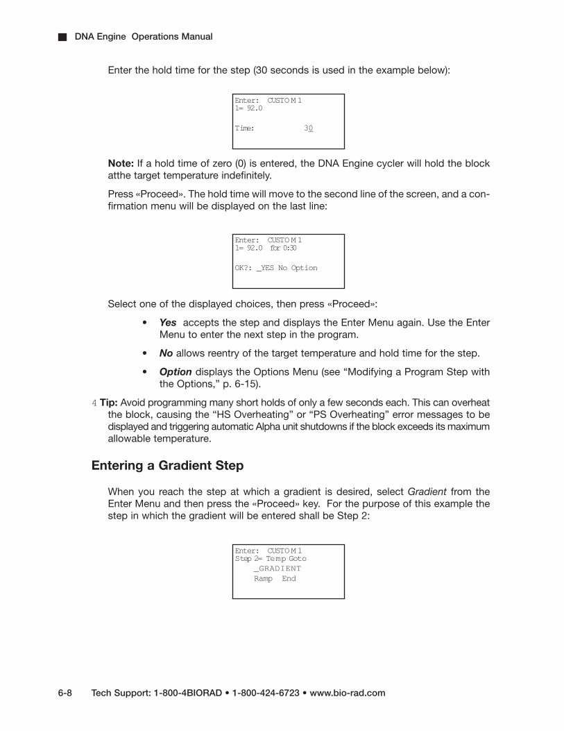
DNA Engine Operations Manual
6-8 Tech Support: 1-800-4BIORAD • 1-800-424-6723 • www.bio-rad.com
Enter the hold time for the step (30 seconds is used in the example below):
Note: If a hold time of zero (0) is entered, the DNA Engine cycler will hold the blockatthe target temperature indefinitely.
Press «Proceed». The hold time will move to the second line of the screen, and a con-firmation menu will be displayed on the last line:
Select one of the displayed choices, then press «Proceed»:
• Yes accepts the step and displays the Enter Menu again. Use the EnterMenu to enter the next step in the program.
• No allows reentry of the target temperature and hold time for the step.
• Option displays the Options Menu (see “Modifying a Program Step withthe Options,” p. 6-15).
4 Tip: Avoid programming many short holds of only a few seconds each. This can overheatthe block, causing the “HS Overheating” or “PS Overheating” error messages to bedisplayed and triggering automatic Alpha unit shutdowns if the block exceeds its maximumallowable temperature.
Entering a Gradient Step
When you reach the step at which a gradient is desired, select Gradient from theEnter Menu and then press the «Proceed» key. For the purpose of this example thestep in which the gradient will be entered shall be Step 2:
Enter: CUSTO M 11= 92.0
Time: 30
Enter: CUSTO M 11= 92.0 for 0:30
OK?: _YES No Option
Enter: CUSTO M 1Step 2= Temp Goto
_GRADIENTRamp End

Creating Programs
Tech Support: 1-800-4BIORAD • 1-800-424-6723 • www.bio-rad.com 6-9
The gradient screen will appear:
Enter the lower limit temperature (for the purposes of this example, 50°), then press«Proceed». The upper temperature screen will appear:
Enter the upper temperature (for the purposes of this example, 70°), then press «Proceed».(Use integers only; decimals are not accepted).
The next screen requires you to enter a hold time for the temperature gradient step:
Enter the hold time in the form of min:sec. Press «Proceed». A confirmation screenwill appear:
Select “Yes” to enter the step into memory and proceed to the next step; select “No” toreject or edit the current step. To preview, select Option, then Preview. Preview gives thepredicted temperatures for each of the wells along the sample block’s long axis. (The linesdo not all appear in the display; use the «Select» keys to scroll up or down.)
Enter: CUSTO M 1
Lower Temp C:
Enter: CUSTO M 150.0
Upper Temp C:
Enter: CUSTO M 12= 50.0 to 70.0
Time:
Enter: CUSTO M 1
2= 50.0 to 70.0for 0:30OK? Yes No Option
Gradient Preview:Column 1- 50.0 leftColumn 2- 51.8Column 3- 53.6

DNA Engine Operations Manual
6-10 Tech Support: 1-800-4BIORAD • 1-800-424-6723 • www.bio-rad.com
Editing a Gradient Step
To edit a gradient step, select Edit from the Main Menu. The program will be displayedas follows:
Use the «Select» keys to scroll to the step you want to edit.
Reviewing a Gradient Program
After the protocol has been run, the Program Complete screen will be displayed. Press the«Proceed» key, and the next screen will display a review of the gradient well temperatures:
Gradient Review:
Column 1- 50.0 left
Column 2- 50.5
Column 3- 51.5
Column 4- 53.2
Column 5- 55.5
Column 6- 58.4
Column 7- 61.8
Column 8- 64.6
Column 9- 66.8
Column 10- 68.4
Column 11- 69.6
Column 12- 70.0 right
Scroll up and down the screen using the «Select» keys. When scrolling the “GradientReview” line will be held constant while the lower 3 lines can be manipulated up or down.The temperatures displayed will be for each of the twelve wells along the long-axis of thesample block. These temperatures will be predicted from an algorithm as a steady-statetemperature of the block and the sample. You may then return to the Main Menu bypressing the «Proceed» key.
List: CUSTO M 11= 92.0 for 0:202= 50.0 to 70.0
for 0:30

Creating Programs
Tech Support: 1-800-4BIORAD • 1-800-424-6723 • www.bio-rad.com 6-11
Using the Gradient Calculator
The gradient calculator predicts, for a given gradient, the temperatures for each ofthe twelve wells along the long-axis of the sample block. These temperatures will bepredicted from an algorithm as a steady-state temperature of the block and thesample. To use the gradient calculator, select the List command from the Main Menuand then press the «Proceed» key. You will see a List screen:
Select Gradient Calculator and press the «Proceed» key :
Enter lower limit temperature of the gradient using the number keys and then pressthe «Proceed» key. Enter the upper temperature for the gradient using the numberkeys and «Proceed» key. You may enter integers without decimal points. The followingscreen will be displayed:
Gradient Calculator:
Column 1- 50.0 left
Column 2- 50.5
Column 3- 51.5
Column 4- 53.2
Column 5- 55.5
Column 6- 58.4
Column 7- 61.8
Column 8- 64.6
Column 9- 66.8
Column 10- 68.4
Column 11- 69.6
Column 12- 70.0 right
You may scroll up and down the screen using the «Select» keys. When scrolling, the“Gradient Calculator” line will be held constant while the lower 3 lines can be manipulatedup or down.
List: Programs_GRADIENT CALCULATO R
Lower Temp C: 50.0 Upper Temp C: 70.0
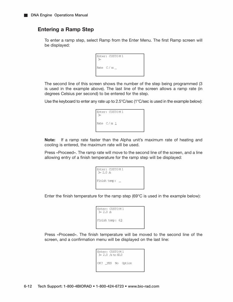
DNA Engine Operations Manual
6-12 Tech Support: 1-800-4BIORAD • 1-800-424-6723 • www.bio-rad.com
Entering a Ramp Step
To enter a ramp step, select Ramp from the Enter Menu. The first Ramp screen willbe displayed:
The second line of this screen shows the number of the step being programmed (3is used in the example above). The last line of the screen allows a ramp rate (indegrees Celsius per second) to be entered for the step.
Use the keyboard to enter any rate up to 2.5°C/sec (1°C/sec is used in the example below):
Note: If a ramp rate faster than the Alpha unit’s maximum rate of heating andcooling is entered, the maximum rate will be used.
Press «Proceed». The ramp rate will move to the second line of the screen, and a lineallowing entry of a finish temperature for the ramp step will be displayed:
Enter the finish temperature for the ramp step (69°C is used in the example below):
Press «Proceed». The finish temperature will be moved to the second line of thescreen, and a confirmation menu will be displayed on the last line:
Enter: CUSTO M 13=
Rate C / s: _
Enter: CUSTO M 13=
Rate C / s: 1
Enter: CUSTO M 13= 2.0 /s
Finish temp: _
Enter: CUSTO M 13= 2.0 /s
Finish temp: 69
Enter: CUSTO M 13= 2.0 /s to 60.0
OK? _YES No Option

Creating Programs
Tech Support: 1-800-4BIORAD • 1-800-424-6723 • www.bio-rad.com 6-13
Select one of the displayed choices, then press «Proceed»:
• Yes accepts the step and displays the Enter Menu again. Use the Enter Menu toenter the next step in the program.
• No allows reentry of the ramp rate and finish temperature.
• Option displays the Options Menu (see “Modifying a Program Step with the Options,”p. 6-11).
4 Tip: A ramp step will not hold the block at its finish temperature. Instead, as soon as finishtemperature is reached, the next step of the program will immediately be executed. Tohold the block for some period of time at a ramp step’s finish temperature, make sure atemperature step immediately follows the ramp step, and program the hold at the finishtemperature into this step.
Entering a GoTo Step
To enter a GoTo step, select GoTo from the Enter Menu. The first GoTo screen will bedisplayed:
The second line of this screen shows the number of the step being programmed (5 is usedin the example above). The last line of the screen allows entry of the number of the stepthe program should cycle back to.
Enter the number of the step the program should cycle back to (1 is used in theexample below):
Press «Proceed». The step number will move to the second line of the screen, and aline allowing an additional number of cycles to be entered will be displayed:
Enter: CUSTO M 15=GoTo
GoTo step: _
Enter: CUSTO M 15=GoTo
GoTo step: 1
Enter: CUSTO M 13=GoTo 1
Addtnl cycles: _

DNA Engine Operations Manual
6-14 Tech Support: 1-800-4BIORAD • 1-800-424-6723 • www.bio-rad.com
Enter the additional number of times the program should cycle back to the step (3 isused in the example below):
Press «Proceed». The number of additional cycles will move to the second line of thescreen, and a confirmation menu will be displayed on the last line:
Select one of the displayed choices, then press «Proceed»:
• Yes accepts the step and displays the Enter Menu again. Use the Enter Menu toenter the next step in the program.
• No allows reentry of the step number and number of additional cycles.
Entering the End Step
To enter the End step, select End from the Enter Menu. The single End screen will bedisplayed:
This screen automatically enters “End” on the second line of the screen, next to a stepnumber, and displays a confirmation menu for the step on the last line of the screen.
Select one of the displayed choices, then press «Proceed»:
• Yes accepts the step, stores the program, and displays the Main Menu.
• No displays the Enter Menu so that additional steps can be added.
Enter: CUSTO M 13=GoTo 1
Addtnl cycles: 3
Enter: CUSTO M 13=GoTo 1, 3 times
OK? _YES No
Enter: CUSTO M 14=End
OK? _YES No
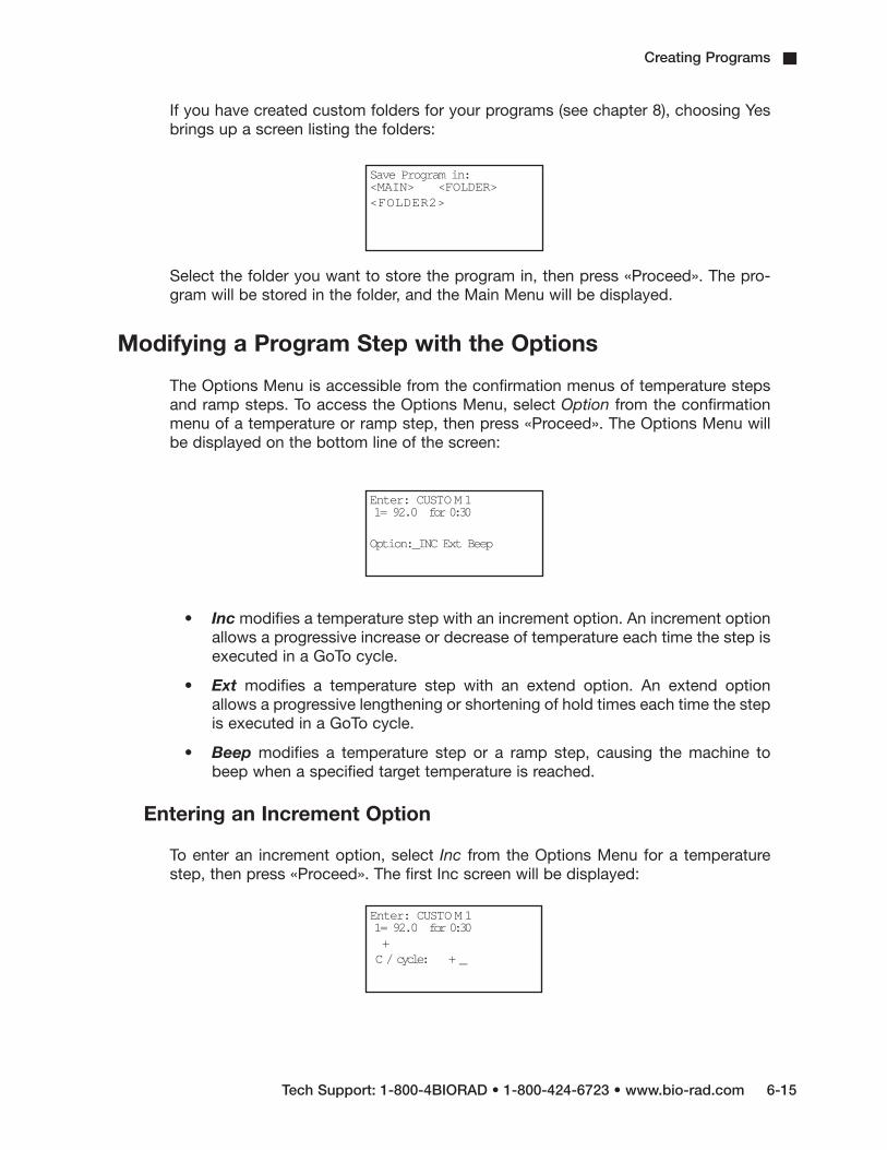
Creating Programs
Tech Support: 1-800-4BIORAD • 1-800-424-6723 • www.bio-rad.com 6-15
If you have created custom folders for your programs (see chapter 8), choosing Yesbrings up a screen listing the folders:
Select the folder you want to store the program in, then press «Proceed». The pro-gram will be stored in the folder, and the Main Menu will be displayed.
Modifying a Program Step with the Options
The Options Menu is accessible from the confirmation menus of temperature stepsand ramp steps. To access the Options Menu, select Option from the confirmationmenu of a temperature or ramp step, then press «Proceed». The Options Menu willbe displayed on the bottom line of the screen:
• Inc modifies a temperature step with an increment option. An increment optionallows a progressive increase or decrease of temperature each time the step isexecuted in a GoTo cycle.
• Ext modifies a temperature step with an extend option. An extend optionallows a progressive lengthening or shortening of hold times each time the stepis executed in a GoTo cycle.
• Beep modifies a temperature step or a ramp step, causing the machine tobeep when a specified target temperature is reached.
Entering an Increment Option
To enter an increment option, select Inc from the Options Menu for a temperaturestep, then press «Proceed». The first Inc screen will be displayed:
Save Program in:<MAIN> <FOLDER><FOLDER2>
Enter: CUSTO M 11= 92.0 for 0:30
Option:_INC Ext Beep
Enter: CUSTO M 11= 92.0 for 0:30+C / cycle: + _

DNA Engine Operations Manual
6-16 Tech Support: 1-800-4BIORAD • 1-800-424-6723 • www.bio-rad.com
The temperature step being modified appears on the second line of this screen. The plussign on the third line means that the screen is set up to enter a progressive increase intemperature per cycle. Press «–» to switch to a minus sign, allowing entry of a progressivedecrease in temperature. Press «Cancel» to change back to a plus sign.
Enter the numerical value of the temperature increase or decrease (1.2 is used in theexample below):
Press «Proceed». The Inc value just entered will move to the third line of the screen,and a confirmation menu will be displayed on the last line:
Select one of the displayed choices, then press «Proceed»:
• Yes accepts the Inc value and displays the Enter Menu again. Use the EnterMenu to enter the next step in the program.
• No allows reentry of the Inc value.
• Option displays the Options Menu again. Use the Options Menu to enter anotheroption for the step.
Entering an Extend Option
To enter an extend option, select Ext from the Options Menu of a temperature step,then press «Proceed». The first Ext screen will be displayed:
As for Inc, the temperature step being modified appears on the second line of thisscreen. The plus sign on the third line means that the screen is set up to enter progressivelengthening of hold time. Press «–» to switch to a minus sign, allowing entry of aprogressive shortening of hold time. Press «Cancel» to change back to a plus sign.
Enter: CUSTO M 11= 92.0 for 0:30+C / cycle: + 1.2
Enter: CUSTO M 11= 92.0 for 0:30+ 1.2 per cycle
OK? _YES No Option
Enter: CUSTO M 11= 92.0 for 0:30+
Sec / cycle: + _

Creating Programs
Tech Support: 1-800-4BIORAD • 1-800-424-6723 • www.bio-rad.com 6-17
Enter the numerical value of the increase or decrease in hold time (1.0 is used in theexample below):
Press «Proceed». The Ext value just entered will move to the third line of the screen, anda confirmation menu will be displayed on the last line:
Select one of the displayed choices, then press «Proceed»:
• Yes accepts the Ext value and displays the Enter Menu again. Use the EnterMenu to enter the next step in the program.
• No allows reentry of the Ext value.
• Option displays the Options Menu again. Use the Options Menu to enteranother option for the step.
Entering a Beep Option
To enter a beep, select Beep from the Options Menu for a temperature step or a rampstep, then press «Proceed». The word “Beep” will be displayed on the third line of thescreen, and a confirmation menu will be displayed on the last line:
Select one of the displayed choices, then press «Proceed»:
• Yes accepts the Beep option and displays the Enter Menu again. Use theEnter Menu to enter the next step in the program.
• No cancels the Beep option.
• Option displays the Options Menu again, if a temperature step is being modified.Use the Options Menu to enter another option for the step. (Option will not bedisplayed if a ramp step is being modified, since Beep is the only option availablefor ramp steps.)
Enter: CUSTO M 11= 92.0 for 0:30+
Sec / cycle: + 1
Enter: CUSTO M 11= 92.0 for 0:30+ 1 sec / cycle
OK? _YES No Option
Enter: CUSTO M 11= 92.0 for 0:30Beep
OK? _YES No Option

DNA Engine Operations Manual
6-18 Tech Support: 1-800-4BIORAD • 1-800-424-6723 • www.bio-rad.com
Revising During Programming
To change values in a program you are entering, follow the procedures described below.This editing method should be used to change just a few values at a time. To make manychanges, or to delete or add entire steps, use Edit mode (see chapter 7).
To Change the Last Value Entered or Menu Option Chosen
Press «Cancel». The choice just made will be cancelled, so that another value may beentered or another menu option chosen. Press «Proceed» after changing a value, so thatthe program will accept it.
To Change All the Values in the Step Being Entered
Repeatedly press «Cancel». Each time you press the key, the cursor will move backwardthrough the values for the step, deleting the values as it moves. When all values for thestep have been deleted, enter new values, or press «Cancel» one more time to displaythe Enter Menu for the step. At this point you can change the step to a different type.
To Change Values for Earlier Steps in the Program
Repeatedly press «Cancel» until the Enter Menu for the step you are working on is displayed.Press «Cancel» one more time to display a list of all steps entered so far. The list willshow the step number and the values for each step, including any options chosen. Thelast-entered steps will be displayed first:
At this point, you can choose to change selected values in program steps, to add anoption, to enter Edit mode, or to delete the entire program.
Press the «Select» keys to scroll through the program. The left «Select» key moves thecursor backward through the steps, and the right «Select» key moves it forward.
• To change selected values or add an option: To change a value, move thecursor to it, then press «Cancel». Enter the new value, then press «Proceed». If youchange your mind, press «Cancel» again; the deleted value will be restored.
Enter: CUSTO M 13= 55.0 for 0:304= 72.0 for 1:005=

Creating Programs
Tech Support: 1-800-4BIORAD • 1-800-424-6723 • www.bio-rad.com 6-19
To add an option to a step, move the cursor to the step number, then press«Proceed». The Edit Menu will be displayed:
Select Option, then press «Proceed», and follow the procedure for adding an option.To abandon the Edit Menu and return to the list of program steps, press «Cancel».
• To enter Edit mode: Move the cursor to the number of the step you wish toedit, then press «Proceed». See chapter 7 for information on entering Editmode. If you do not wish to enter Edit mode, press «Cancel». The screen willreturn to the list of program steps.
• To delete the program: Position the cursor on any step number and press«Cancel». A cancellation confirmation screen will be displayed.
Select Yes, then press «Proceed». The program will be deleted, and the Main Menuwill be displayed.
Deleting a Program
To delete a program after at least one complete step has been entered, see “RevisingDuring Programming,” (p. 6-18).
To delete a program before one complete step has been entered, repeatedly press«Cancel». The cursor will move backward through the step’s values, deleting them asit goes. When all values have been deleted, keep pressing «Cancel» to move backwardthrough Enter mode screens until the Main Menu reappears, at which point you canbegin a new program.
Keeping a Permanent Record of Programs
Occasionally in the course of repairing a defective DNA Engine cycler, it is necessaryto replace the chip that stores all custom user protocols. To avoid losing your protocolsin such an event, always maintain an up-to-date record of them. Protocols may beprinted out using the List utility (see chapter 8), stored on a computer using theEasy Engine™ software, or written down in a notebook.
Enter: CUSTO M 12= 92.0 for 0:40
_Edit InsertStep: Option Delete
Enter: CUSTO M 1
Cancel program?_YES NO


7-1
Editing Programs7Editing a Stored Program . . . . . . . . . . . . . . . . . . . . . . . . . . . . . . . . . . . . . . . . . . . . . . . . .7-2
Initiating Editing . . . . . . . . . . . . . . . . . . . . . . . . . . . . . . . . . . . . . . . . . . . . . . . . . . . .7-2
Editing the Program . . . . . . . . . . . . . . . . . . . . . . . . . . . . . . . . . . . . . . . . . . . . . . . .7-3
Inserting a New Step . . . . . . . . . . . . . . . . . . . . . . . . . . . . . . . . . . . . . . . . . .7-4
Deleting a Step . . . . . . . . . . . . . . . . . . . . . . . . . . . . . . . . . . . . . . . . . . . . . .7-4
Adding an Option . . . . . . . . . . . . . . . . . . . . . . . . . . . . . . . . . . . . . . . . . . . .7-4
Saving an Edited Program . . . . . . . . . . . . . . . . . . . . . . . . . . . . . . . . . . . . . . . . . . . . . . . .7-4
Cancelling Editing Changes . . . . . . . . . . . . . . . . . . . . . . . . . . . . . . . . . . . . . . . . . . . . . . .7-5

DNA Engine Operations Manual
7-2 Tech Support: 1-800-4BIORAD • 1-800-424-6723 • www.bio-rad.com
Editing a Stored Program
The DNA Engine® cycler’s editing tools, available through Edit on the Main Menu,make it easy to extensively edit stored programs by:
• Changing individual values in program steps
• Adding new steps
• Deleting steps
• Adding options to temperature and ramp steps.
Note: The editing tools do not include a renaming function. To rename a program,see “Renaming a Program,” chapter 8.
Initiating Editing
To initiate editing, select Edit from the Main Menu, then press «Proceed». One of twotypes of screen will be displayed, depending on whether your programs have been storedin the <MAIN> folder or in custom folders.
• If all programs have been stored in <MAIN>:
The screen will list the contents of <MAIN>:
Select the program to be edited, then press «Proceed».
• If programs have been stored in custom folders:
The screen will list all the folders residing in the machine:
Select the folder containing the program, then press «Proceed». A list of all programs inthe folder will be displayed. Select the program to be edited (CUSTOM1 is used in thefollowing and all succeeding examples in this chapter), then press «Proceed».
In either instance, after you press «Proceed», the first editing screen will be displayed.
4 Tip: To retain the original version of a program, copy the program (see “Copying a Program,”chapter 8), and then edit the copy.
Edit: <MAIN>_CUSTOM1 CUSTOM2 CUSTOM3 QUIKSTEP2-STEP 3-STEP
Edit: _<MAIN> <FOLDER1><FOLDER2>
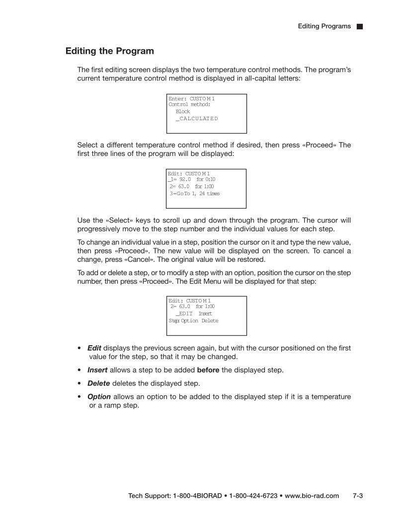
Editing Programs
Tech Support: 1-800-4BIORAD • 1-800-424-6723 • www.bio-rad.com 7-3
Editing the Program
The first editing screen displays the two temperature control methods. The program’scurrent temperature control method is displayed in all-capital letters:
Select a different temperature control method if desired, then press «Proceed» Thefirst three lines of the program will be displayed:
Use the «Select» keys to scroll up and down through the program. The cursor willprogressively move to the step number and the individual values for each step.
To change an individual value in a step, position the cursor on it and type the new value,then press «Proceed». The new value will be displayed on the screen. To cancel achange, press «Cancel». The original value will be restored.
To add or delete a step, or to modify a step with an option, position the cursor on the stepnumber, then press «Proceed». The Edit Menu will be displayed for that step:
• Edit displays the previous screen again, but with the cursor positioned on the firstvalue for the step, so that it may be changed.
• Insert allows a step to be added before the displayed step.
• Delete deletes the displayed step.
• Option allows an option to be added to the displayed step if it is a temperatureor a ramp step.
Enter: CUSTO M 1Control method:
Block_CALCULATED
Edit: CUSTO M 1_1= 92.0 for 0:102= 63.0 for 1:003=GoTo 1, 24 times
Edit: CUSTO M 12= 63.0 for 1:00_EDIT Insert
Step:Option Delete

DNA Engine Operations Manual
7-4 Tech Support: 1-800-4BIORAD • 1-800-424-6723 • www.bio-rad.com
Inserting a New Step
To insert a new step, select Insert from the Edit Menu, then press «Proceed». The EnterMenu will be displayed for the new step (a new step 2 is added in the example below):
Use the Enter Menu to create the new step (see “Entering the Program’s Steps,” chapter 6).When the step is complete, select Yes from the confirmation menu, then press «Proceed».The program being edited will be displayed again, with the new step appearing among thelisted steps.
Deleting a Step
To delete a step, select Delete from the Edit Menu, then press «Proceed». The step willimmediately be deleted, and the program being edited will be displayed again, minusthe deleted step.
To cancel a deletion, see “Cancelling Editing Changes,” p. 7-5.
Note: Be careful when using Delete. Once a step has been deleted, it cannot be recoveredwithout abandoning all editing changes that have been made in the program. This could beinconvenient if the program has been extensively edited.
Adding an Option
To add an option to a step, select Option from the Edit Menu, then press «Proceed». Theoption menu will be displayed for the step. Add the desired option to the step (see“Modifying a Program Step with the Options,” chapter 6). When the option is complete,select Yes from the confirmation menu, then press «Proceed». The steps of the programbeing edited will be displayed again, with the new option appearing in the list.
Saving an Edited Program
To save an edited program, use the right «Select» key to scroll to the End step of theprogram. Position the cursor on the number for the step, then press «Proceed». A lineallowing the editing session to be ended will be displayed on the last line of the screen:
Edit: CUSTO M 1
Step 2= _TEMP GoToRamp End
Edit: CUSTO M 12=End
Step: _END Insert

Editing Programs
Tech Support: 1-800-4BIORAD • 1-800-424-6723 • www.bio-rad.com 7-5
• End saves the changes and displays the Main Menu. This ends the editing session.
• Insert allows another step to be added just before the End step.
Cancelling Editing Changes
To cancel all editing changes made to a program, use the «Select» keys to move thecursor to any step number, then press «Cancel». A cancellation confirmation screenwill be displayed:
Select Yes, then press «Proceed». All editing changes will be abandoned, and theMain Menu will be displayed.
Edit: CUSTO M 1
Cancel changes?_YES No


8-1
Using the Utilities8Locating a Stored Program . . . . . . . . . . . . . . . . . . . . . . . . . . . . . . . . . . . . . . . . . . . . . . . 8-2
File Utilities . . . . . . . . . . . . . . . . . . . . . . . . . . . . . . . . . . . . . . . . . . . . . . . . . . . . . . . . . . . . 8-2
Creating a Folder . . . . . . . . . . . . . . . . . . . . . . . . . . . . . . . . . . . . . . . . . . . . . . . . . . 8-3
Assigning a Password to a Folder . . . . . . . . . . . . . . . . . . . . . . . . . . . . . . . . . . . . .8-3
Deleting a Folder . . . . . . . . . . . . . . . . . . . . . . . . . . . . . . . . . . . . . . . . . . . . . . . . . . .8-4
Copying a Program . . . . . . . . . . . . . . . . . . . . . . . . . . . . . . . . . . . . . . . . . . . . . . . . .8-4
Renaming a Program . . . . . . . . . . . . . . . . . . . . . . . . . . . . . . . . . . . . . . . . . . . . . . .8-5
Moving a Program . . . . . . . . . . . . . . . . . . . . . . . . . . . . . . . . . . . . . . . . . . . . . . . . . .8-5
Deleting a Program . . . . . . . . . . . . . . . . . . . . . . . . . . . . . . . . . . . . . . . . . . . . . . . . .8-5
List Utilities . . . . . . . . . . . . . . . . . . . . . . . . . . . . . . . . . . . . . . . . . . . . . . . . . . . . . . . . . . . . 8-5
Viewing a Program in the LCD Window . . . . . . . . . . . . . . . . . . . . . . . . . . . . . . . . .8-6
Printing a Program . . . . . . . . . . . . . . . . . . . . . . . . . . . . . . . . . . . . . . . . . . . . . . . . .8-6
Setup Utilities . . . . . . . . . . . . . . . . . . . . . . . . . . . . . . . . . . . . . . . . . . . . . . . . . . . . . . . . . . 8-7
Choosing a Remote Port . . . . . . . . . . . . . . . . . . . . . . . . . . . . . . . . . . . . . . . . . . . . .8-7
Choosing a Printer Port . . . . . . . . . . . . . . . . . . . . . . . . . . . . . . . . . . . . . . . . . . . . . .8-8
Choosing a Minimum Block Temperature for the Hot Bonnet® Lid . . . . . . . . . . . .8–8
Choosing a Temperature Control Method for the Hot Bonnet Lid . . . . . . . . . . . . .8–8
Determining the Software Version Number . . . . . . . . . . . . . . . . . . . . . . . . . . . . . . .8-9

DNA Engine Operations Manual
8-2 Tech Support: 1-800-4BIORAD • 1-800-424-6723 • www.bio-rad.com
Locating a Stored Program
Many of the DNA Engine® cycler’s utilities require you to locate a program stored inthe machine. The actions necessary to do this depend on whether your programshave been stored in the <MAIN> folder or in custom folders.
• If all programs have been stored in <MAIN>:
The screen will list all the programs that <MAIN> contains:
Select the desired program from this list.
• If programs have been stored in custom folders:
The screen will list all the folders residing in the machine:
Select the folder containing the program, then press «Proceed». A list of all programsin the folder will be displayed. Select the desired program, then press «Proceed».
File Utilities
Use these utilities, available from the Files Menu, to accomplish the following tasks:
• Create folders to store programs in
• Assign passwords to folders
• Copy, delete, rename, or move programs
To display the Files Menu, select Files from the Main Menu, then press «Proceed»:
Copy: <MAIN>_CUSTOM1 CUSTO M 2QUIKSTEP 2-STEP3-STEP EXTEND
Copy: <MAIN> <FOLDER1><FOLDER2> <FOLDER3>
Files: _COPY DeleteMove RenameFolder Secure

Using the Utilities
Tech Support: 1-800-4BIORAD • 1-800-424-6723 • www.bio-rad.com 8-3
Creating a Folder
The DNA Engine cycler’s memory can hold up to 11 folders, including the <MAIN> folder.New programs are placed in the <MAIN> folder by default unless a different folder isspecified.
To create a folder, select Folder from the Files Menu, then press «Proceed». A namingscreen will be displayed:
Name the folder, using the instructions found under “Naming the Program” in chapter6, then press «Proceed». The name will be assigned to the new folder, the folder willbe stored, and the Main Menu will be displayed.
Assigning a Password to a Folder
Protocols in a password-protected folder cannot be edited, renamed, or deleted, norcan new protocols be placed in the folder without the password. Users withoutknowledge of the password can still run, copy, and view a program.
Note: A password cannot be assigned to the <MAIN> folder.
To assign a password to a folder, select Secure from the Files Menu, then press«Proceed». A list of all folders in the machine will be displayed. Select the desiredfolder (other than <MAIN>), then press «Proceed». The password assignment screenwill be displayed:
Valid passwords consist of numbers up to four digits long. For passwords of three digitsor less, press «Proceed» after the password has been entered. Passwords four digits longwill be automatically accepted as soon as typed, and the Main Menu will be displayed.
Passwords can be changed at any time. Follow the steps described above to selectthe desired folder, then press «Proceed». A screen asking for the old password willbe displayed:
Enter the old password, then press «Proceed». The password assignment screen willbe displayed. Enter the new password, then press «Proceed». The new password willbe assigned to the folder, and the Main Menu will be displayed again.
New Folder:
Name: A
Secure: <FOLDER1>
New password: _
Secure: <FOLDER1>
Old password: _

DNA Engine Operations Manual
8-4 Tech Support: 1-800-4BIORAD • 1-800-424-6723 • www.bio-rad.com
Deleting a Folder
A folder must be empty before it can be deleted. After all programs have beenmoved or deleted from the folder, select Delete from the Files Menu, then press«Proceed». A list of all folders in the machine will be displayed. Select the folder tobe deleted, then press «Proceed». A confirmation screen will be displayed:
Select Yes, then press «Proceed». The folder will be deleted, and the Main Menu willbe displayed.
To cancel the deletion, press «Cancel», or select No and press «Proceed».
Copying a Program
The copy utility copies a program and gives the copy a new name. Copies can beplaced in the original folder or a new one.
To copy a program, select Copy from the Files Menu, then press «Proceed». Locatethe program to be copied (see “Locating a Stored Program,” p. 8-2), then press«Proceed». If more than one folder of programs is present in the machine, a screenallowing you to specify the folder the program will be copied to will be displayed:
Select a folder to copy the program to, then press «Proceed». A naming screen willbe displayed:
Name the copied program (see “Naming the Program,” chapter 6), then press«Proceed». The program will be copied to the specified folder under the new name,and the Main Menu will be displayed.
Delete: <FOLDER1>
Delete empty folder?_YES No
Copy CUSTOM1 to:_<FOLDER1> <FOLDER2><FOLDER3>
Copy CUSTOM1 to:
New name: A

Using the Utilities
Tech Support: 1-800-4BIORAD • 1-800-424-6723 • www.bio-rad.com 8-5
Renaming a Program
To rename a program, select Rename from the File Menu, then press «Proceed».Locate the program to be renamed (see “Locating a Stored Program,” p. 8-2), thenpress «Proceed». A naming screen will be displayed:
Name the new program (see “Naming the Program,” chapter 6), then press «Proceed».The program will be renamed and stored, and the Main Menu will be displayed.
Moving a Program
To move a program, select Move from the Files Menu, then press «Proceed». Locatethe program to be moved (see “Locating a Stored Program,” p. 8-2), then press«Proceed». A screen listing all folders will be displayed. Select the folder the programshould be moved to, then press «Proceed». The program will be moved to the newfolder, and the Main Menu will be displayed.
Deleting a Program
To delete a program, select Delete from the Files Menu, then press «Proceed».Locate the program to be deleted (see “Locating a Stored Program,” p. 8-2), thenpress «Proceed». A confirmation screen will be displayed:
Select Yes, then press «Proceed». The program will be deleted, and the Main Menuwill be displayed.
To cancel the deletion, press «Cancel», or select No and press «Proceed».
List Utilities
Use these utilities, available under List, to accomplish the following task:
• View and print program steps
Rename: CUSTO M 1
New name: A
Delete: CUSTO M 3
Delete program?_YES No

DNA Engine Operations Manual
8-6 Tech Support: 1-800-4BIORAD • 1-800-424-6723 • www.bio-rad.com
Viewing a Program in the LCD Window
To view a program in the LCD window, select List from the Main Menu, then press«Proceed». Locate the program to be viewed (see “Locating a Stored Program,” p.8-2), then press «Proceed». What happens next depends on whether a printer is con-nected to the DNA Engine cycler.
• If a printer is connected:
A screen will be displayed asking whether the program should be sent to the printer:
Select No, then press «Proceed». The program will be listed in the LCD window. Thefirst listed screen will show the program’s control method. Press «Proceed» to viewsubsequent screens listing each program step, including any options. Use the«Select» keys to scroll up or down through the steps one line at a time. To return tothe Main Menu, press «Cancel» at any time, or press either the right «Select» key or«Proceed» when the last step appears on the screen.
• If a printer is not connected:
The program will immediately be listed in the LCD window. You will not be given theoption of printing at all.
Note: Listed programs cannot be edited. To edit programs, select Edit from the MainMenu (see chapter 7).
Printing a Program
First ensure that the DNA Engine cycler is connected to a printer. If no printer is con-nected, you will not be given the option of printing at all. The DNA Engine cycler’sparallel interface is compatible with most serial and laser printers, the Epson LX-810dot-matrix printer parallel interface, and dot-matrix printers using interfaces similar tothe Epson’s. Use a standard DB-25/Centronics parallel interface cable to connect theDNA Engine cycler’s parallel port to the printer’s parallel port. A null-modem serialcable will usually be required to connect the DNA Engine cycler’s serial port to aprinter’s serial port.
Use the Setup utilities to choose a printer port for the DNA Engine cycler (see“Choosing a Printer Port,” p. 8-8).
Select List from the Main Menu, then press «Proceed». Locate the program to beprinted (see “Locating a Stored Program,” p. 8-2), then press «Proceed». The screenasking whether the program should be sent to the printer will be displayed (seeabove). Select Yes, then press «Proceed». The program will be printed.
List: CUSTO M 1
Printer output?Yes _NO

Using the Utilities
Tech Support: 1-800-4BIORAD • 1-800-424-6723 • www.bio-rad.com 8-7
Setup Utilities
Use these utilities, available from the Setup Menu, to accomplish the following tasks:
• Choose a remote port and a printer port
• Choose a temperature control method for the Hot Bonnet heated lid
• Look up the DNA Engine cycler’s software version number
To display the Setup Menu, select Setup from the Main Menu, then press «Proceed»:
Choosing a Remote Port
To choose either the serial port or the IEEE-488 port, select Remote from the SetupMenu, then press «Proceed». The port selection screen will be displayed:
The cursor will be positioned at the port currently in use.
To choose the serial port, select Serial, then press «Proceed». The cursor will moveto Serial, and a line allowing a baud rate to be specified will be displayed on the lastline of the screen:
Select a baud rate, then press «Proceed». The remote port assignment will changeto serial, and the Main Menu will be displayed.
To choose the IEEE-488 port, select IEEE-488, then press «Proceed». The cursor willmove to IEEE-488, and a line allowing the DNA Engine cycler to be assigned an IEEE-488 address will be displayed on the last line of the screen:
Setup:_REMOTE PrinterLid Version
Remote:Serial _IEEE-488
Printer:_SERIAL IEEE-488
Baud: 9600 2400_1200
Printer:Serial _IEEE-488
Address (0-30): 0

DNA Engine Operations Manual
8-8 Tech Support: 1-800-4BIORAD • 1-800-424-6723 • www.bio-rad.com
The instrument’s current address will be displayed. To change it, enter a number from0–30, then press «Proceed». The remote port assignment will change to IEEE-488,the address number will be assigned to the instrument, and the Main Menu will bedisplayed.
Note: Do not choose 0 for the machine address unless the DNA Engine cycler will bea controller in a network (see chapter 9).
Choosing a Printer Port
To choose a printer port, select Printer from the Setup Menu, then press «Proceed».The port selection screen will be displayed:
Select the desired port, then press «Proceed». If serial was chosen, specify theprinter’s baud rate as for “Choosing a Remote Port” (p. 8-7).
Choosing a Minimum Block Temperature for the Hot Bonnet Lid
To set a minimum block temperature below which the Hot Bonnet lid will automati-cally turn off, select Lid from the Setup Menu, then press «Proceed». The followingscreen will be displayed:
Select «MINIMUM» and press «Proceed». The following screen will be displayed:
Use the keypad to enter the temperature, then press «Proceed» to enter the valueand return to the Main Menu.
Choosing a Temperature Control Mode for the Hot Bonnet Lid
Two temperature control modes are available for the Hot Bonnet lid:
• Tracking: Offsets the temperature of the heated inner lid at least a specifiednumber of degrees Celsius in comparison to the temperature of the sample block.
Printer:Parallel _SERIAL
Lid:
Mode _MINIMUM
Lid Minimum:
Turn off heatedlid below: 23 C

Using the Utilities
Tech Support: 1-800-4BIORAD • 1-800-424-6723 • www.bio-rad.com 8-9
• Constant: Keeps the inner lid at a specified temperature (°C).
The DNA Engine cycler is set for the tracking mode at the factory, using an offset of5°C, which should be adequate for most reactions. The constant mode is provided forunusual reactions requiring the inner lid to be hot at all times. When using the constantmode, specify a lid temperature at least 10°C higher than any temperature used in theprotocol; we suggest 105°C.
To choose a control mode, select Lid from the Setup Menu, then press «Proceed».The following screen will appear:
Select «Mode», then press «Proceed» (to select a minimum block temperature, see“Choosing a Minimum Block Temperature for the Hot Bonnet Lid” above).
The mode currently in use will be selected in the screen; select a different controlmode if desired, then press «Proceed» to enter the mode and return to the main menu.
If the tracking mode is chosen, a lid offset (up to 45°C above the block, but not toexceed 110°C) must be specified. A line for this will appear at the bottom of thescreen: “Lid offset °C: 15.” If the constant mode is chosen, a lid target temperature(up to 110°C) must be specified. A line for this will appear at the bottom of the screen:“Lid target °C: _.” In either case, enter a number, then press «Proceed». Thetracking control mode will be implemented, and the Main Menu will be displayed.
Determining the Software Version Number
At times it is necessary to determine the version number of the software installed in theDNA Engine cycler (e.g., to report a problem to Bio-Rad). To do this, select Version fromthe Setup Menu, then press «Proceed». The current version number will be displayed:
The top line reports the software version number (1.1L in the example). The othertwo lines refer to the four “pages” that the software has been broken into and theirassociated versions (L in the example).
Bio-Rad periodically updates the DNA Engine cyler software to incorporate new fea-tures or allow new Alpha™ units to be used. Most upgrades are available free ofcharge for units under warranty and may be installed into a DNA Engine cycler elec-tronically from a desktop computer. Contact your Bio-Rad sales representative or anauthorized distributor for details. Occasionally upgrades may require a hardwarechange. These upgrades require return of the DNA Engine base to Bio-Rad or anauthorized distributor.
Lid:
_MODE Minimum
Version: 1.1L
CTRL L EXEC LUSER L COMM L

8-10 Tech Support: 1-800-4BIORAD • 1-800-424-6723 • www.bio-rad.com
DNA Engine Operations Manual

9-1
Networking9Overview of Networking . . . . . . . . . . . . . . . . . . . . . . . . . . . . . . . . . . . . . . . . . . . . . . . . . 9-2
Networking Instruments without a Computer . . . . . . . . . . . . . . . . . . . . . . . . . . . . . . . 9-2
Connecting the Instruments . . . . . . . . . . . . . . . . . . . . . . . . . . . . . . . . . . . . . . . . . . 9-2
Assigning Address Numbers to Instruments . . . . . . . . . . . . . . . . . . . . . . . . . . . . .9-2
Running a Protocol on Networked Instruments . . . . . . . . . . . . . . . . . . . . . . . . . . .9-3
Networking Instruments with a Computer . . . . . . . . . . . . . . . . . . . . . . . . . . . . . . . . . . 9-4
Creating a Computer-Controlled IEEE-488 Network . . . . . . . . . . . . . . . . . . . . . . .9-5
Creating a Computer-Controlled RS-232 Network . . . . . . . . . . . . . . . . . . . . . . . . .9-5

DNA Engine Operations Manual
9-2 Tech Support: 1-800-4BIORAD • 1-800-424-6723 • www.bio-rad.com
Overview of Networking
Up to 15 instruments consisting of any combination of DNA Engine® (orDNA Engine Tetrad®) cyclers may be networked, with or without a computer as thecontroller. When networking with a computer, all the instruments are controlled fromthe computer’s keyboard. When networking without a computer, a specially desig-nated DNA Engine cycler controls the other instruments in the network. Anycombination of single- and dual-block Alpha™ units may be loaded into networkedinstruments, and different protocols can be run independently on them.
Networked instruments can help save time for a busy laboratory. For example, in aDNA Engine cycler–controlled network, protocols can be entered into the controllinginstrument and then be run on all the other instruments connected to the network.
Networking Instruments without a Computer
Connecting the Instruments
Connect DNA Engine and DNA Engine Tetrad cyclers via the IEEE-488 port on theback of each instrument (see figs. 2-3 and 12-4), using high-quality cables. Althoughseveral connection configurations are possible, we recommend a simple daisy chainor star pattern. The DNA Engine cycler’s IEEE-488 interface is fully compatible withboth the IEEE-488.2 and the IEEE-488.1 standards.
Assigning Address Numbers to Instruments
Each instrument must have a unique address number, which is assigned from its con-trol panel. Address numbers cannot be assigned from the controller.
To assign an address number to a instrument, select Setup from the Main Menu, thenpress «Proceed». The Setup Menu will be displayed:
Select Remote, then press «Proceed». A screen allowing choice of a port will bedisplayed:
Setup:_REMOTE PrinterLid Version
Remote:_SERIAL IEEE-448

Networking
Tech Support: 1-800-4BIORAD • 1-800-424-6723 • www.bio-rad.com 9-3
Select IEEE-488, then press «Proceed». The remote addressing screen will be displayed:
Enter an address number for the instrument. Set the controller DNA Engine cycler’saddress to 0. Give the other instruments in the network any number from 1 to 30.Press «Cancel» to delete a number and enter a new one.
Running a Protocol on Networked Instruments
To run a protocol on networked instruments, use the controller to select a protocol(see “Choosing a Stored Protocol to Run,” chapter 5), then press «Proceed». The net-work screen for the controller will be displayed:
The protocol will be identified on the top line (2-STEP in the example above). Thesingle asterisk in the upper right-hand corner indicates that a single-block Alpha unitis loaded into the controller. “Local” indicates that this is the controller’s networkscreen, and “96V“ indicates the type of Alpha unit loaded into the controller.
If a Dual Alpha™ unit is loaded into the controller, press «Proceed» until the letter des-ignating the desired block is displayed after the asterisk in the upper right-handcorner of the screen. The letter A designates the right-hand block, and the letter Bthe left-hand one (e.g., *A, *B).
To run the protocol on the controller’s block, press «Proceed». One or more screensfor setting up the protocol’s temperature control method will be displayed (see“Running a Protocol,” chapter 5). When these screens have been worked through,the protocol will begin running.
To run the protocol on a different instrument’s block, press «Block» until the screenidentifies the desired block (22 in the example below):
The instrument’s address number will be identified in the upper right-hand corner ofthe screen. “Remote” indicates that this is the network screen for a slave unit, and“60V” indicates the type of Alpha unit that has been selected. The status light for theselected block will flash on the control panel of the instrument holding the block.
Remote:Serial _IEEE-448
Address (0-30): 0
Run: 2-STEP on *
Block: Local (96V)
Run: 2-STEP on 22
Block: Remote 60V

DNA Engine Operations Manual
9-4 Tech Support: 1-800-4BIORAD • 1-800-424-6723 • www.bio-rad.com
If the right or left block of a dual-block Alpha unit has been selected, an A or B willappear after the address number (e.g., 7-3A for the right-hand block in a Dual Alphaunit loaded into quadrant 3 of a DNA Engine Tetrad at address 7. See figure 12-1 fora diagram of the layout of quadrants in the DNA Engine Tetrad cycler).
Press «Cancel» at any time to abandon the selection process and display the MainMenu again.
When the desired block is identified in the LCD window, press «Proceed». When youhave worked through the screens that set up the protocol’s temperature controlmethod, the protocol will begin running.
The protocol’s runtime screen will appear on the controller’s LCD window. The LCDwindow of the instrument holding the active block will continue to show whateverscreen it was displaying before the protocol began running.
Press «Block» to display the Main Menu on the controller again. Repeat the proce-dure to run protocols on other networked blocks. Press «Block» on the controller toprogressively display the runtime screens of all networked blocks that are runningprotocols.
While protocols are running, other DNA Engine cycler functions (Edit, Enter, Files,etc.) can be accessed on any individual instrument in the network, from that instru-ment’s front panel.
Networking Instruments with a Computer
For users who wish to write their own software interface for computer control of Bio-Rad DNA Engine® line thermal cyclers, including the DNA Engine (PTC-0200),Bio-Rad provides a set of ASCII commands, or Remote Command Sets, for com-munication with the cyclers. These may be downloaded from www.bio-rad.com, orobtained from Bio-Rad Technical Support.A computer-controlled network can beconnected via IEEE-488 cables or RS-232 (serial) cables. In either case, the com-puter acts as the controller of the network and uses the driver software tocommunicate with the networked instruments.
Establishing Communication Using the Remote Interfaces
The DNA Engine remote control interface is based on the IEEE-488.2 standard. TheGPIB interface is fully compatible with both this standard and the IEEE-488.1 hard-ware standard.
The serial remote interface uses an identical command set which includes the IEEE-488.2 required common commands. On a DNA Engine, multiple commands orqueries may be contained in one message as long as they are separated by semi-colons. Corresponding responses to any queries will be returned in a singlemessage, also separated by semicolons.

Networking
Tech Support: 1-800-4BIORAD • 1-800-424-6723 • www.bio-rad.com 9-5
The IEEE-488 GPIB Remote Interface
To connect DNA Engine (and DNA Engine Tetrad) cyclers in a computer-controlledIEEE-488 network, the computer must be equipped with an IEEE-488 (GPIB) inter-face card. Connect the instruments and assign addresses as described under“Networking Instruments Without a Computer” (p. 9-2). Make sure that none of thenetworked instruments have been assigned IEEE-488 address 0 as this address isreserved for a DNA Engine acting as system controller and will cause communicationproblems with the computer.
All inputs (commands or queries) to the unit must be terminated with a NEWLINEcharacter (ASCII 10), an ^END hardware level command on the last data byte of themessage, or a NEWLINE^END combination following the last data byte of the mes-sage. The preferred terminator is the NEWLINE^END combination. All outputs fromthe unit (query responses) are terminated with a NEWLINE^END.
The RS-232 Serial Remote Interface
In a computer-controlled RS-232 (serial) network, each instrument in the network isconnected directly to the controlling computer via a serial port. The number of instru-ments that can be included in such a network thus depends on the number of serialports available on the controlling computer. Use high-quality null modem serialcables to connect the serial port on each instrument (see figs. 2-3 and 12-4) to aserial port on the computer.
Use the Setup utilities to configure each instrument for serial communications (see“Choosing a Remote Port,” chapter 8, and select the serial port and the 9600 baudrate). The Port Settings should also specify 8-bit data bytes, 1 stop bit, and no parity.
All inputs to the unit must be terminated with a NEWLINE (ASCII 10). Each outputfrom the DNA Engine is terminated with a RETURN (ASCII 13) NEWLINE combina-tion.


10-1
Maintenance10Cleaning the DNA Engine Cycler . . . . . . . . . . . . . . . . . . . . . . . . . . . . . . . . . . . . . . . . . 10-2
Cleaning the Chassis and Block . . . . . . . . . . . . . . . . . . . . . . . . . . . . . . . . . . . . . 10-2
Cleaning the Air Vents . . . . . . . . . . . . . . . . . . . . . . . . . . . . . . . . . . . . . . . . . . . . . . .8-3
Cleaning Radioactive or Biohazardous Materials out of the Block . . . . . . . . . . .10-3
Changing the Fuses . . . . . . . . . . . . . . . . . . . . . . . . . . . . . . . . . . . . . . . . . . . . . . . . . . . . 10-3

DNA Engine Operations Manual
10-2 Tech Support: 1-800-4BIORAD • 1-800-424-6723 • www.bio-rad.com
Cleaning the DNA Engine® Cycler
Cleaning the Chassis and Block
Clean the outside of the DNA Engine cycler and Alpha™ unit with a damp, soft cloth ortissue whenever something has been spilled on it or the chassis is dusty. A mild soapsolution may be used if needed.
Clean block wells with swabs moistened with water, 95% ethanol, or a 1:100 dilutionof bleach in water (see the Slide Chambers Alpha Unit Operations Manual for instruc-tions on cleaning the Slide Chambers™ Alpha unit’s slide slots). If using bleach, swabwells with water afterward to remove all traces of bleach. Clean spilled liquids out ofthe block as soon as possible; dried fluids can be difficult to remove. Do not clean theblock with caustic or strongly alkaline solutions (e.g., strong soaps, ammonia, bleachat a higher concentration than specified above). These will damage the block’s pro-tective anodized coating, possibly causing electrical shorting.
If you use oil in the block (a practice not recommended by Bio-Rad; see “Using Oil toThermally Couple Sample Vessels to the Block,” chapter 4), clean the wells wheneverthe oil has become discolored or contains particulate matter. Use a swab to determinewhether cleaning is needed. Clean the block with 95% ethanol as described above. Oilbuildup must be prevented. Old oil harbors dirt, which interferes with vessel seatingand diminishes thermal coupling of sample vessels to the block.
Caution: Do not pour any cleaning solution into the block’s wells and thenheat the block, in an attempt to clean it. Severe damage to theblock, the heated lid, and the chassis will result.
Cleaning the Air Vents
Clean the air intake and exhaust vents with a soft-bristle brush, a damp cloth, or avacuum cleaner whenever dust is visible in them. The air intake vents are located onthe bottom, lower front edge, and back of the machine; the air exhaust vents arelocated on both sides (see figs. 2-1, 2-3, and 2-4). If these vents become cloggedwith dust and debris, airflow to the Alpha unit’s heat sink is hampered, causing per-formance problems related to overheating. The air intake vents are particularly likelyto collect dust since their holes are much smaller than those of the air exhaust vents.
Tip: To prevent problems with overheating, institute a regular program of checking fordust buildup, particularly for robotics installations.

Maintenance
Tech Support: 1-800-4BIORAD • 1-800-424-6723 • www.bio-rad.com 10-3
Cleaning Radioactive or Biohazardous Materials out of theBlock
When cleaning instruments that have been running radioactive or biohazardous reac-tions, consult your institution’s radiation safety officer or biosafety officer regardingcleaning methods, monitoring, and disposing of contaminated materials.
Changing the Fuses
The circuits in the DNA Engine cycler are protected by two fuses (6.3A fast-acting,5x20mm). When a fuse blows, the DNA Engine cycler immediately shuts down andcannot be turned back on. The machine records the event as a power loss, so if aprotocol is running when a fuse blows, the machine will resume the run when the fuseis replaced and power restored (see “Resuming a Protocol after a Power Outage,”chapter 5).
Warning: The DNA Engine cycler incorporates neutral fusing, which meansthat live power may still be available inside the unit even when afuse has blown or been removed. Never open the DNA Enginebase. You could receive a serious electrical shock. Opening thebase will also void your warranty.
1. Disconnect the power cord from the back of the instrument. Move the powerswitch to the “0” (off) position.
2. Insert one corner of a small flat-head screwdriver just under the fuse plug (fig. 10-1A),and gently pry the plug loose. Pull the plug straight out as far as it will go, then pushit downward to expose the fuses (fig. 10-2B).
3. Remove both fuses and replace them with new ones (it is impossible to visuallydetermine which fuse is blown). You may also test the fuses with an ohmmeter todetermine which is defective and replace just that one.
4. Gently press the fuse cover back in place, and reconnect the power cord.
Figure 10-1 A, Removing the fuse plug. B, Location of the fuses in the opened plug.
A B
Fuse plug
Fuse plug
FuseFuse
Screwdriver


11-1
Troubleshooting11Error Messages . . . . . . . . . . . . . . . . . . . . . . . . . . . . . . . . . . . . . . . . . . . . . . . . . . . . . . . 11-2
Problems Related to Protocols . . . . . . . . . . . . . . . . . . . . . . . . . . . . . . . . . . . . . . . . . . 11-6
Problems Related to Environmental Conditions, Setup, and Maintenance . . . . . . . 11-8
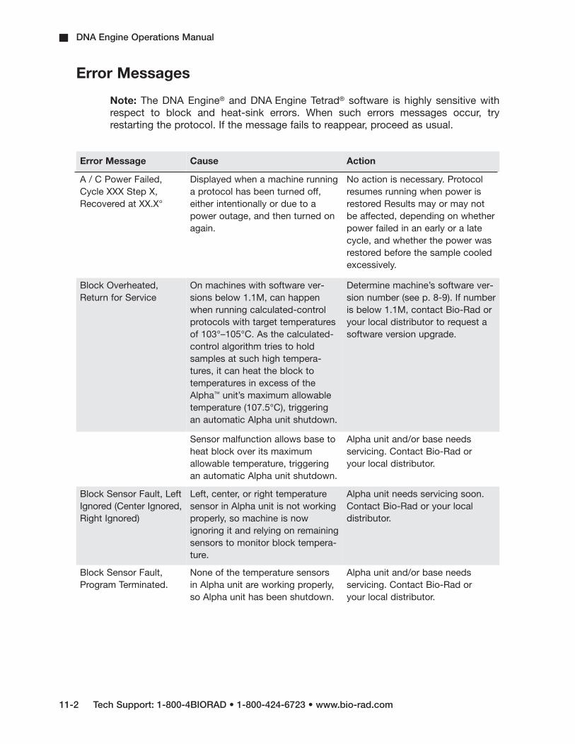
DNA Engine Operations Manual
11-2 Tech Support: 1-800-4BIORAD • 1-800-424-6723 • www.bio-rad.com
Error Messages
Note: The DNA Engine® and DNA Engine Tetrad® software is highly sensitive withrespect to block and heat-sink errors. When such errors messages occur, tryrestarting the protocol. If the message fails to reappear, proceed as usual.
Error Message Cause Action
A / C Power Failed,Cycle XXX Step X,Recovered at XX.X°
Displayed when a machine runninga protocol has been turned off,either intentionally or due to apower outage, and then turned onagain.
No action is necessary. Protocolresumes running when power isrestored Results may or may notbe affected, depending on whetherpower failed in an early or a latecycle, and whether the power wasrestored before the sample cooledexcessively.
Block Overheated,Return for Service
On machines with software ver-sions below 1.1M, can happenwhen running calculated-controlprotocols with target temperaturesof 103°–105°C. As the calculated-control algorithm tries to holdsamples at such high tempera-tures, it can heat the block totemperatures in excess of theAlpha™ unit’s maximum allowabletemperature (107.5°C), triggeringan automatic Alpha unit shutdown.
Determine machine’s software ver-sion number (see p. 8-9). If numberis below 1.1M, contact Bio-Rad oryour local distributor to request asoftware version upgrade.
Sensor malfunction allows base toheat block over its maximumallowable temperature, triggeringan automatic Alpha unit shutdown.
Alpha unit and/or base needs servicing. Contact Bio-Rad or your local distributor.
Block Sensor Fault, LeftIgnored (Center Ignored,Right Ignored)
Left, center, or right temperaturesensor in Alpha unit is not workingproperly, so machine is nowignoring it and relying on remainingsensors to monitor block tempera-ture.
Alpha unit needs servicing soon.Contact Bio-Rad or your local distributor.
Block Sensor Fault,Program Terminated.
None of the temperature sensorsin Alpha unit are working properly,so Alpha unit has been shutdown.
Alpha unit and/or base needs servicing. Contact Bio-Rad or your local distributor.

Troubleshooting
Tech Support: 1-800-4BIORAD • 1-800-424-6723 • www.bio-rad.com 11-3
Error Message Cause and Result Action
Calc Control, ProbeMode Invalid
Runtime error indicating a gradientstep is being programmed underProbe Control mode.
Change to Calc control mode.
Gradient Fault, ServiceAlpha soon.
Displayed at end of run. Indicatesgradient was not achieved within20 sec of block reaching target.
Alpha unit and / or base needsservicing. Contact Bio-Rad or yourlocal distributor.
Gradient Program,Invalid Alpha Type.
Runtime error indicating gradient isbeing programmed for an Alphamodule other than a 96V.
Use 96V Alpha nodule.
Heated Lid Fault,Program Terminated.
Lid sensor failed during preheat,so Alpha unit has been shut down.
Heated lid or base needs servicingContact Bio-Rad or your local dis-tributor.
HS Overheated,Program Terminated
Machines are not getting enoughair, or air being taken in is warmerthan 31°C.
Make sure machine gets enoughair and that temperature of airbeing taken in is 31°C or cooler(see p. 3-3). Correct air supplyproblems and run protocol again.If error message persists, basemay need servicing. ContactBio-Rad or your local distributor.
Machine is running a protocol con-sisting of many cycles of only a fewseconds each. Alpha unit heat sinkdoes not have time to dissipateheat generated by rapid cycling.Eventually its maximum allowabletemperature is exceeded, andAlpha unit is shut down.
Contact Bio-Rad or your local dis-tributor to discuss protocol.
Sensor malfunction has allowedbase to heat block over its max-imum allowable temperature(107.5°C), triggering automaticAlpha unit shutdown.
Alpha unit and / or base needsservicing. Contact Bio-Rad oryour local distributor.
HS Overheating, Check Air Flow
See causes for “HS Overheated,Program Terminated.”
See actions for “HS Overheated,Program Terminated.”
HS/PS Sensor Fault,Program Terminated.
Heat sink sensor in Alpha unit andpower supply sensor in base arenot working, so Alpha unit hasbeen shut down.
Alpha unit or base needs servicing.Contact Bio-Rad or your local dis-tributor.

DNA Engine Operations Manual
11-4 Tech Support: 1-800-4BIORAD • 1-800-424-6723 • www.bio-rad.com
Error Message Cause and Result Action
HS Sensor Fault, AltControl Mode
Alpha unit heat sink sensor is notfunctioning properly, so machinehas begun estimating heat sinktemperature based on other tem-perature sensor readings.
Alpha unit needs servicing soon.Contact Bio-Rad or your local dis-tributor.
HS Sensor Fault, LeftIgnored.
Same as previous Same as previous
HS Sensor Fault, RightIgnored.
Same as previous Same as previous
Internal Fan Fault,Return for Service
Fan inside base is not working, soAlpha unit has been shut down.
Fan must be repaired. ContactBio-Rad or your local distributor.
Lid Sensor Fault, Lid Was Disabled.
Heated lid is giving unexpectedtemperature readings, so base hasturned it off. Protocols can still berun, but reactions may fail becauseof condensation in vessels.
Alpha unit needs servicing soon.Contact Bio-Rad or your local dis-tributor.
L/R Power Imbalance Thermoelectric units in Alpha unitblock are not heating uniformly, somachine begins delivering equalpower to all heating elements.Protocols may still be run, butreactions may fail due to unevenblock temperatures.
Alpha unit needs servicing soon.Contact Bio-Rad or your local distributor.
Memory Is Corrupt! Rarely seen message indicatingthat memory has been corruptedby a static shock or other unusualelectronic incident.
Base needs servicing. ContactBio-Rad or your local distributor.
No Memory Available!
All available memory has beenfilled.
Delete unused protocols andfolders from memory. Reduce sizeof stored programs by using GoToand the Inc and Ext options (seechapter 6).
Probe Sensor Fault, Used Calc Control
Either probe sensor is not workingproperly or a probe-control pro-tocol was run without probe beinginstalled. Machine has switchedtemperature control method to calculated control.
Make sure probe is installed whenrunning probe-control programs. Iferror message persists, replaceprobe.

Troubleshooting
Tech Support: 1-800-4BIORAD • 1-800-424-6723 • www.bio-rad.com 11-5
Error Message Cause and Result Action
PS Overheated, Program Terminated
Machine is not getting enough air,or air being taken in is warmerthan 31°C.
Make sure that machine is gettingenough air and that temperature ofair being taken in is 31°C or cooler(see p. 3-3). Correct any air supplyproblems and run protocol again.If error message persists, basemay need servicing. ContactBio-Rad or your local distributor.
Machine is running a protocol con-sisting of many cycles of only a fewseconds each. Alpha unit heat sinkdoes not have time to dissipateheat generated by rapid cycling.Eventually its maximum allowabletemperature is exceeded, andAlpha unit is shut down.
Contact Bio-Rad or your local dis-tributor to discuss protocol.
PS Overheating, Check Air Flow
See causes for “PS Overheating,Program Terminated.”
See actions for “PS Overheating,Program Terminated.”
PS Sensor Fault, Temp Ignored
Power supply sensor is notworking properly. Protocols canstill be run, but machine should beserviced soon to repair sensor.
Base needs servicing. ContactBio-Rad or your local distributor.
Slow Block Cycling, Service Alpha Soon
Alpha unit block has not reachedtarget temperature within expectedtime. Unit will begin beeping, andwill continue to beep until targettemperature is reached, protocol ismanually progressed to its nextstep (see p.5-8), or protocol run ishalted. Problem often results frommachine not getting enough air, ortaking air that is warmer than 31°C.
Make sure that machine is gettingenough air and that temperature ofair being taken in is 31°C or cooler(see p. 3-3). Correct any air supplyproblems and run protocol again.If error message persists, softwareupgrade may be needed or basemay need servicing. ContactBio-Rad or your local distributor.
Slow Lid Cycling, Service Alpha Soon
Alpha unit lid has not reachedtarget temperature within expectedtime. Unit will begin beeping, andwill continue to beep until targettemperature is reached, protocol ismanually progressed to its nextstep (see p.5-8), or protocol run ishalted.
Alpha unit lid needs servicingsoon. Contact Bio-Rad or yourlocal distributor.
Unit Failure/Unit X Failure(Tetrad)
The self-test has failed because ofa problem with the base or theAlpha unit.
Contact Bio-Rad or your local dis-tributor.

DNA Engine Operations Manual
11-6 Tech Support: 1-800-4BIORAD • 1-800-424-6723 • www.bio-rad.com
Problems Related to Protocols
Following is a general description of some common problems related to the protocolsand reaction components in sequencing and amplification applications. For a moredetailed discussion of protocols and reactions, see Current Protocols in MolecularBiology (F. Ausubel et al., eds., John Wiley & Sons), specifically chapters 7 (DNAsequencing), 14 (in-situ hybridization and immunology), and 15 (polymerase chainreaction).
Error Message Cause and Result Action
Reaction is working, butbroad low-molecularweight band is seen in gels.
“Primer-dimer” material often pro-duces a broad band in the <100 bpregion of gels.
If obtaining appropriate reactionproduct/s, no need to change anything.
Minimize “primer-dimer” productionby designing primers with no 3'self-complementary.
Reoptimize magnesium concentra-tion and annealing temperature tomaximize desired product andminimize “primer-dimers”.
Reaction working, butunexpected extra prod-ucts or smear is seen.
Nonspecific hybridization occurringduring setup.
Program a hot start into the protocol.
Reaction component concentrationtoo high or too low.
Check concentrations of compo-nents. May need to reoptimizemagnesium concentration.
Annealing temperature too low. Reoptimize annealing temperature.
Protocol contains a wrong value. Use List utility to check protocol’stemperature control method, tem-peratures, and times.
Template not of sufficient purity. Check extraction and purificationprotocols. Add additional purifica-tion steps if necessary.
Multiple templates or host DNA insequencing reactions.
Check nucleic acid preparationsby gel electrophoresis.

Troubleshooting
Tech Support: 1-800-4BIORAD • 1-800-424-6723 • www.bio-rad.com 11-7
Problem Cause Action
No reaction productsobtained.
Wrong protocol used. Re-run reaction using correct protocol.
Protocol contains a wrong value. Use List utility to check protocol’stemperature control method, tem-peratures, and times.
Reaction component omitted frommixture.
Check reaction assembly protocol,ensuring that mixture containsappropriate components in correctconcentrations.
Denaturation temperature too low.
Use >92°C for denaturation.
Annealing temperature too high forprimers.
Check for appropriate annealingtemperatures of primers, usingavailable computer programs orempirical testing.
Wrong temperature control methodused.
Use List utility to check tempera-ture control method for protocol;change if needed.
Probe failed, causing machine torun protocol under calculated control.
Check screen for probe failureerror message. Probe may needservicing or replacing. ContactBio-Rad or your local distributor.
Probe not filled with correctamount of oil.
Fill probe tube with correct amountof oil. (see p. 4-11).
Reaction mix contains an inhibitor(e.g., heme from blood).
Spike a complete reaction mix witha control template and primer set.
Reaction vessels not making goodthermal contact with sample block.
Use only high-quality tubes/platesthat fit block snugly. Ensure thatwells are free of foreign materialsthat would interfere with tube/plateseating.

DNA Engine Operations Manual
11-8 Tech Support: 1-800-4BIORAD • 1-800-424-6723 • www.bio-rad.com
Problems Related to Environmental Conditions, Setup, andMaintenance
Problem Cause Action
Frequent shutdownsdue to overheating.Frequent “Slow BlockCycling,” and “HSOverheating” error messages.
Machine is not receiving enoughair.
Make sure air intake vents ar notobstructed by dust, debris, orpaper. Remove light collections ofdust and debris with damp cloth.Vacuum out heavy collections.Remove any papers placed underthe machine at least 10cm fromvertical surfaces.
Air flowing into vents is not <31°C.
Check temperature of air enteringair intake vents, following procedureon p. 3-3. If higher than 31°C, usetable 3-1 to troubleshoot andremove cause / s.
Dust and debris clog-ging up air intake vents.
Failure to regularly check forbuildup.
Remove light collections dampcloth. Vacuum out heavy collections.

A-1
Appendix A: WarrantyInformationA
The DNA Engine® (PTC-0200) thermal cycler is warranted against defects in materialsand workmanship. For specific warranty information, contact your local Bio-Radoffice. If any defects should occur during the warranty period, Bio-Rad will replacethe defective parts without charge. However, the following defects are specificallyexcluded:
1. Defects caused by improper operation or by improper packaging of returnedgoods.
2. Repair or modifications done by anyone other than Bio-Rad Laboratories.
3. Use with tubes, plates, or sealing materials not specified by Bio-RadLaboratories for use with the DNA Engine thermal cycler.
4. Deliberate or accidental misuse.
5. Damage caused by disaster.
6. Damage due to use of improper solvent or sample.
The warranty does not apply to fuses.
For inquiry or request for repair service, contact Bio-Rad Laboratories after confirmingthe model and serial number of your instrument.

B-1
B Appendix B: Factory-Installed Protocols
Standard 2-step PCR protocol
STD-2Step Temp Time1 95 4:002 95 :303 65 :304 GOTO 2, 29X5 46 END
Standard 3-step PCR protocol
STD-31 95 4:002 95 :303 55 :304 72 :305 GOTO 2, 29X6 72 7:007 48 END
Touchdown PCR protocol
TCHDOWN1 95 4:002 95 :303 60 :30
(Increment -0.5°C/cycle)4 72 :305 GOTO 2, 29X6 95 :307 45 :308 72 309 GOTO 6, 29X10 72 7:0011 412 END
2-step Fast PCR protocol usingiTaq™ polymerase
iTAQ-FSTStep Temp Time1 98 :302 92 :013 70 :104 GOTO 2, 34X5 72 :156 END
2-step PCR protocol using iProof™
high-fidelity polymerase for small,intermediate, and long templates
iPRF1kb1 95 2:002 95 :053 72 :304 GOTO 2, 219X5 72 10:006 END
iPRF8kb1 95 2:002 95 :053 72 4:004 GOTO 2, 19X5 72 10:006 END
iPRF15kb1 95 2:002 95 :053 72 7:304 GOTO 2, 19X5 72 10:006 END

DNA Engine Operations Manual
B-2 Tech Support: 1-800-4BIORAD • 1-800-424-6723 • www.bio-rad.com
2-step RT PCR protocol
RTPCR-2Step Temp Time1 37 60:002 95 5:003 95 :304 65 :305 GOTO 3, 39X6 72 7:007 48 END
3-step RT PCR protocol
RTPCR-31 37 60:002 95 5:003 95 :304 55 :305 72 :306 GOTO 3, 39X7 72 7:008 49 END
2-step nested primer protocol
NEST PR21 95 4:002 95 :303 65 :304 GOTO 2, 39X5 72 7:006 47 95 :308 65 :309 GOTO 7, 39X10 72 7:0011 412 END
3-step nested primer protocol
NEST PR3Step Temp Time1 95 4:002 95 :303 55 :304 72 :305 GOTO 2, 39X6 72 7:007 48 95 :309 55 :3010 72 :3011 GOTO 8, 39X12 72 7:0013 414 END
2-step long PCR protocol usingiTaq polymerase
LONG-21 95 4:002 95 :303 65 3:00 Ext 15s/cycle4 GOTO 2, 34X5 72 7:006 47 END
3-step long PCR protocol usingiTaq polymerase
LONG-31 95 4:002 95 :303 55 :304 72 3:00 Ext 15s/cycle5 GOTO 2, 34X6 72 7:007 48 END

Tech Support: 1-800-4BIORAD • 1-800-424-6723 • www.bio-rad.com In-1
Index
AAir supply requirements
ensuring adequate air supply 3-3
ensuring air is cool enough 3-4
troubleshooting problems with 3-4
Alpha units
closing 4-5
installing 4-4
models 2-4
opening 4-5
removing 4-5
BBaud rate, setting 8-7
Beep option. See Programs: options, types of
Bleach, using in block 10-2
CChill-out liquid wax 4-7
Cleaning
air vents 10-2
and biohazardous materials 10-3
and radioactive materials 10-3, 4-13
chassis and block 10-2
removing oil from block 10-2
solutions to use 4-13
Condensation in tubes following holds 4-7
Control panel 2-2

DNA Engine Operations Manual
In-2 Tech Support: 1-800-4BIORAD • 1-800-424-6723 • www.bio-rad.com
keys 4-3
lights 4-3
using 4-3
DDocumentation conventions
graphic vi
terminology vi
typographic vi
EElectromagnetic interference v
Environmental requirements 3-2–3-3
Error messages 11-2
Explanation of symbols iv
Extend option. See Programs: options, types of
FFCC warning v
Fuses
changing 10-3
HHot Bonnet lid
adjusting lid pressure 4-8–4-9
temperature control methods 8-8
IIncrement option. See Programs: options, types of
Instant incubation 5-9
LLayout
back view 2-3
bottom view 2-3
control panel 2-2
Index
Tech Support: 1-800-4BIORAD • 1-800-424-6723 • www.bio-rad.com In-3
front view 2-2
MMenus
Edit Menu 7-2
Enter Menu 6-5
Files Menu 8-2
Main Menu 4-2
Options Menu 6-5
Setup Menu 8-7
Microseal
‘A’ film 4-8
‘B’ adhesive seals 4-8
‘F’ foil 4-8
'P'/'P+' pads 4-8
Moto Alpha unit 2-4
NNetworking
general information 9-2
with computer as controller 9-4
setting up an IEEE-488 network 9-5
setting up an RS-232 network 9-5
with DNA Engine cycler as controller 9-2
assigning address numbers 9-2
connecting machines 9-2
running protocols 9-3
OOil, use of in block. See Sample vessels
Operation
turning machine on 4-2
PPacking checklist 3-2

DNA Engine Operations Manual
In-4 Tech Support: 1-800-4BIORAD • 1-800-424-6723 • www.bio-rad.com
Passwords. See Utilities: files: assigning password to folder
Ports 2-5, 4-3
IEEE-488 2-3
parallel (printer) 2-3
RS-232 2-3
Power cord
location of jack 2-3
plugging in 3-2
Power supply requirements 3-3
acceptable power cords 3-3
Programming
choosing a temperature control method 6-6
deleting a program 6-19
entering steps
beep option 6-17
end step 6-14
extend option 6-16
GoTo step 6-13
gradient step 6-8
increment option 6-15
ramp step 6-12
temperature step 6-7
general process 6-5
initiating a program 6-5
modifying block--control programs 6-5
modifying programs designed for other machines 6-5
naming a program 6-6
setting a lengthy hold time 6-8
Programs
designing 6-2–6-5
choosing temperature control method. See Temperature control methods
translating protocol into programs 6-3

Index
Tech Support: 1-800-4BIORAD • 1-800-424-6723 • www.bio-rad.com In-5
using GoTo steps to shorten programs 6-3
editing 7-2, 7-3
adding an option 7-4
cancelling editing changes 7-5
deleting step 7-4
inserting new step 7-4
saving edited program 7-4
finding in machine 5-2, 7-2, 8-2
options, types of 6-2, 6-15
program steps, types of 6-2
renaming. See Utilities: file
Protocols
and power failure 5-8
factory-installed 5-2, B-1
manually stepping through 5-7
pausing while running 5-7
printing logs for runs 5-6–5-7
running
choosing block to run protocol on 5-3
choosing protocol to run 5-2
reading completion screen 5-6
reading runtime screen 5-5
setting up temperature control method 5-3
three steps of 5-2
stopping while running 5-8
protocols
adjusting for sample vessel type 4-6
SSafety
general instructions 1-3
guideline for safe use v
warnings iv

DNA Engine Operations Manual
In-6 Tech Support: 1-800-4BIORAD • 1-800-424-6723 • www.bio-rad.com
Sample vessel
selection chart 4-11
Sample vessels
ensuring good thermal contact 4-10
loading into block 4-9
sealing
reason for 4-7
with Hot Bonnet lid and caps/film 4-7
with oil or wax 4-7
selection 4-6
0.2 ml tubes 4-6
0.5 ml tubes 4-6
microplates 4-6
use of oil to improve thermal contact with block 4-10
Self-test 4-2
Setting machine up. See also Alpha units, installing
Shipping instructions A-1
Specifications 2-5
TTemperature control methods
block control 6-4
calculated control 6-4
UUtilities
file
assigning password to folder 8-3
copying program 8-4
creating folder 8-3
deleting a program 8-5
deleting folder 8-4
moving a program 8-5

Index
Tech Support: 1-800-4BIORAD • 1-800-424-6723 • www.bio-rad.com In-7
printing a program 8-6
renaming programs 8-5
viewing a program in LCD window 8-6
setup 8-7
choosing a printer port 8-8
choosing a remote port 8-7
choosing a temperature control method for the Hot Bonnet lid 8-8
determining software version number 8-9
WWarranty information A-1

DNA Engine Dyad and Dyad Systems Operations Manual
In-8 Tech Support: 1-800-4BIORAD • 1-800-424-6723 • www.bio-rad.com

Declaration of Conformity
Bio-Rad Laboratories, Inc., 1000 Alfred Nobel Drive, Hercules, California,94547, U.S.A., declares that the product
PTC0200, The DNA Engine® Thermal Cycler
to which this declaration relates, is in conformity to the following standards or normative documents.
IEC61010-1EN61326: CLASS A
following the provisions of the 73/23/EEC, 89/336/EEC & 93/68/EECDirective.
This product is imported into the EU by Bio-Rad Laboratories, Ltd., Bio-RadHouse, Maxted Road, Hemel Hempstead (London area), HertfordshireHP2 7DX England.
13 September, 2004date of issue
Brad CrutchfieldVice President
11142 rev B


Technical Service:Call your local Bio-Rad office, or in the U.S. call 1-800-4BIORAD (1-800-424-6723).
Bulletin 05434 US/EG Rev E 05-0869 1205 Sig 1205
Life ScienceGroup
Bio-Rad Laboratories, Inc.
Web site www.bio-rad.com USA (800) 4BIORAD Australia 02 9914 2800 Austria (01)-877 89 01 Belgium 09-385 55 11 Brazil 55 21 2527 3454 Canada (905) 712-2771 China (86 21) 6426 0808 Czech Republic + 420 2 41 43 05 32 Denmark 44 52 10 00 Finland 09 804 22 00 France 01 47 95 69 65 Germany 089 318 84-0 Greece 30 210 777 4396 Hong Kong (852) 2789 3300 Hungary 36 1 455 8800 India (91-124)-2398112/3/4, 5018111, 6450092/93 Israel 03 951 4127 Italy 39 02 216091 Japan 03-5811-6270 Korea 82-2-3473-4460 Latin America 305-894-5950 Mexico 55-52-00-05-20 The Netherlands 0318-540666 New Zealand 64 9 415 2280 Norway 23 38 41 30 Poland + 48 22 331 99 99 Portugal 351-21-472-7700 Russia 7 095 721 1404 Singapore 65-64153188 South Africa 00 27 11 4428508 Spain 34 91 590 52 00 Sweden 08 555 12700 Switzerland 061 717 95 55 Taiwan (886 2) 2578 7189/2578 7241 United Kingdom 020 8328 2000