dn05002/d buck-boost converter for 3 a leds
TRANSCRIPT
DN05002/D
May 2011, rev. 0 www.onsemi.com 1
Design Note – DN05002/D
Buck-Boost Converter for 3 A LEDs
Device Application Input Voltage Output Power Topology I/O Isolation
NCP3020A NTMFS5844
Battery-powered high current LED
driver 10 to 25 Vdc 60 Watts Buck-Boost None
Output Voltage 15 – 22Vdc Nominal Current 1 – 3A
Nominal Efficiency 82 - 89%
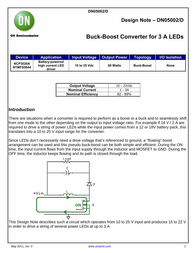
Introduction There are situations when a converter is required to perform as a boost or a buck and to seamlessly shift from one mode to the other depending on the output to input voltage ratio. For example if 18 V / 2 A are required to drive a string of power LEDs while the input power comes from a 12 or 18V battery pack, this translates into a 10 to 25 V input range for the converter. Since LEDs don’t necessarily need a drive voltage that’s referenced to ground, a “floating” boost arrangement can be used and this pseudo buck-boost can be both simple and efficient. During the ON time, the input current flows from the input supply through the inductor and MOSFET to GND. During the OFF time, the inductor keeps flowing and its path is closed through the load.
This Design Note describes such a circuit which operates from 10 to 25 V input and produces 15 to 22 V in order to drive a string of several power LEDs at up to 3 A.

DN05002/D
May 2011, rev.0 www.onsemi.com 2
Circuit Description
Having a 5 to 28 V input range, the NCP3020A buck controller is well suited for the application. The high side driver is used to drive the boost MOSFET while the low side one is left open. The output current is sensed by Rcs1 resistor and the current mirror circuit consisting of Q2 – Q5 makes sure a fraction of this current flows through resistor R3. The voltage across R3 is then fed to the FB pin of the controller. Q6 and adjacent components help implement a soft start function. At power-up, Q6 is initially off and resistor R9 appears in series with R3, ensuring a low current at start. Then the voltage across C10 slowly increases and Q6 gradually turns on and shunts R9 and from that moment on, R3 alone controls the output current. The ON-OFF switch is placed in a low current path providing power just for the controller. This arrangement allows a low cost switch to be used, but the user must be aware that approximately 0.5 mA of leakage current exists due to the current mirror. If this situation is not acceptable, than the shown switch should be by-passed and a series power MOSFET should be used in the power path to turn on and off the converter. MOSFET Q1 and diode D1 may seem oversized for a circuit required to provide up to 3 A, but peak currents can reach in excess of 10 A and efficiency will suffer if weaker parts are used. The efficiency was measured with an electronic load simulating a string of LED’s requiring 22 V at up to 3 A.

DN05002/D
May 2011, rev.0 www.onsemi.com 3
Schematic
Start-up

DN05002/D
May 2011, rev.0 www.onsemi.com 4
Transient Response For this test, a second load was switched on and off in parallel with the main load. The converter successfully maintains a constant output current. The transient spikes are totally acceptable since
this application does not require a fast response.
Output Current Adjustment

DN05002/D
May 2011, rev.0 www.onsemi.com 5
Output current is set by resistor R2 which can be chosen according to the table below.
Iout (A) R2 (Ω) 1 187
1.5 267 2 348 3 511
Key Features
Seamless “buck to boost” transition High efficiency Constant output current Simplicity
References Data sheet NTMFS5844NL: 60 V, 60 A, 12 m Ohm Single N-Channel Power MOSFET in SO-8FL Data sheet NCP3020: 28V Synchronous Buck Controller
1
1© 2011 ON Semiconductor.
Disclaimer: ON Semiconductor is providing this design note “AS IS” and does not assume any liability arising from its use; nor does ON Semiconductor convey any license to its or any third party’s intellectual property rights. This document is provided only to assist customers in evaluation of the referenced circuit implementation and the recipient assumes all liability and risk associated with its use, including, but not limited to, compliance with all regulatory standards. ON Semiconductor may change any of its products at any time, without notice. Design note created by Michael Borza, e-mail: [email protected]