dmx2-18 user manual
TRANSCRIPT
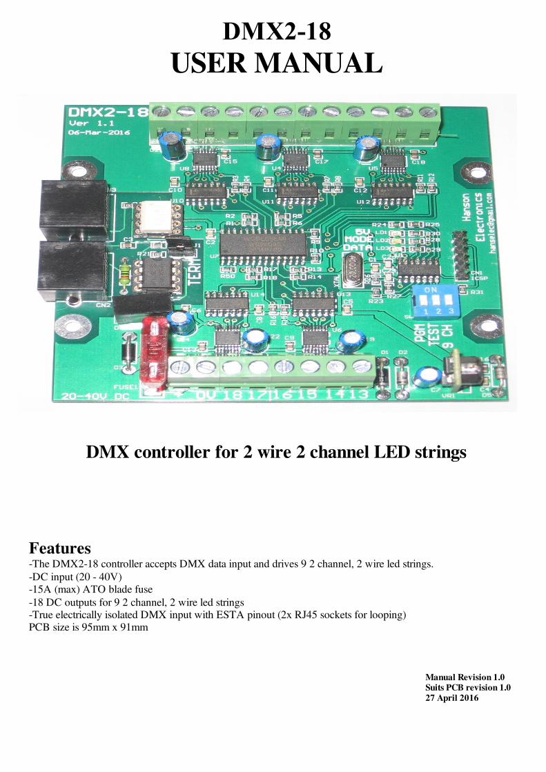
DMX2-18
USER MANUAL
DMX controller for 2 wire 2 channel LED strings
Features-The DMX2-18 controller accepts DMX data input and drives 9 2 channel, 2 wire led strings.-DC input (20 - 40V)-15A (max) ATO blade fuse-18 DC outputs for 9 2 channel, 2 wire led strings -True electrically isolated DMX input with ESTA pinout (2x RJ45 sockets for looping)PCB size is 95mm x 91mm
Manual Revision 1.0Suits PCB revision 1.027 April 2016

ConnectionsDmx Data There are 2 RJ45 dmx sockets on the board. These are designed for loop in and loop out. If the DMX2-18 is the last dmx device on the dmx cable then the signal should be terminated with the terminationjumper. Basically if only 1 cable is plugged in to the dmx sockets then the termination jumper should be installed.If both sockets are used then the termination jumper should be left off. The DMX2-18 uses the ESTA pinout. If connecting to a LOR device (dongle or controller) a crossover cable oradaptor will need to be connected in between.
DC Power Input The board will control any DC voltage between 20 and 40V . The DMX2-18 comes supplied with a 10A fuse fitted.Fuses up to 15A can be used. It is recommended changing the fuse to the closest size for the total current that theboard will be supplying.
Dimmer Outputs There are 18 channel outputs for controlling 9 2 channel 2 wire led strings. A DC voltage in the range of 20 to 40Vcan be used. The maximum load per string is 2 Amps, but remember that the overall limit is 15 Amps. This means that you can'tturn on all 9 strings with the maximum load.
See the Connection Example section for the method of connecting lights.
ICSP Connector An ICSP (in circuit serial programming) header connector is provided for initial programming of the microprocessor andfor program (firmware) updates.
USING THE DMX2-18Status LedsThere are 3 small LEDs near the centre of the PCB adjacent to the micro. Red led-5V Power, Blue led-MODE, Green led-DATA
-Red led 5V power
-Blue MODE led flashing slowly. Green DATA led off. Test modeTest mode takes precedence over normal running so errors/status message other than test mode won’t be displayed if in testmode.-Blue MODE led on solid. Green DATA led flashing 10 Hz. Normal run mode. Dmx packets being received-Blue MODE led on solid. Green DATA led off. Normal run mode. No dmx data-Blue MODE led flashing 10Hz. Green DATA led off. PGM/Address setting mode. No valid address yet-Blue MODE led flashing 10Hz. Green DATA led on. PGM/Address setting mode. Val i d address
received
9 CHThere is a switch that allows the DMX2-18 to work in 9 channel (9 CH) mode. This means that both channels of a string will be dimmedat the same setting. Using the DMX2-18 in this mode only 9 DMX addresses are used.
Start ChannelThe start channel is set via the PGM switch and data being sent to the board. DMX addresses can be anywhere between 1 and512. The address of the DMX2-18 can be anywhere in the range of 1 to 495 (a start address of 495 uses the addresses from495 to the maximum 512). If the address is set outside of this range an error is indicated via the 2 status leds. See Status Leds.The start channel can be changed at any time by turning on the PGM switch and sending the data. The start address is sentand stored as 2 8 bit numbers. For a start address of 1-255 the 2nd address/channel should be 0. For addresses over 255 (255-495) the 2nd start address channel is set to 1 and the 1st address channel is set to the start address minus 255.
When you receive your DMX2-18 it will have a DMX start address of 1. That is, it will respond to channels 1 to 18. Tochange the start address perform the following procedure:• Power up the DMX2-18.• Connect a DMX source of DMX data like a sequencer, test software or dedicated start channel programmer (like
-2-

da_start from http://www.da-share.com/software/da_start/ ) etc that you can set at least channels 1 & 2 to a DMXaddress to the full 0-255 range (not a 0-100% setting)
• Set DMX channel 1 to value 1..255 to the required setting for the new DMX start address• Set DMX channel 2 to a non-zero value if it’s required to add 256 to the new DMX start address• Turn on the PGM dipswitch. The MODE led will flash and the DATA led will be off.• After a valid start address in the range of 1-495 is received the DATA led will turn on. The new DMX start address is
then stored in the EEPROM• Turn off the PGM switch and the DMX2-18 is ready to use with the new start address.• If using da_start then ensure DMX18 is selected to allow the correct address range to be selected Test ModeThere is a switch which places the control into a test mode. In this mode a test program runs and all 18 outputs are cycledthrough. This mode allows for soak testing of lights without the need for a source of dmx data. The control will cycle throughthe modes of testing from 1 channel on at a time, 1 string at a time, 1 half of all strings, other half of all strings etc.
Connection Example Typical connection arrangement showing 2 wire 2 channel led string. The strings connect between channels 1 and 2 for string1, 3 and 4 for string 2 etc. The order of the lights on the 2 channel 2 wire lights can be changed by swapping the pairs of wiresfrom 1 and 2 to 2 and 1. As the leds on a string are typically relatively closely spaced the difference probably isn’t noticeableor worth the effort.
-3-

Firmware Updates Firmware updates can be loaded through the ICSP header with a Pickit3 pic programmer. Pin1 of the ICSP header is marked on the pcb and is shown to the left. Ensure the pin 1 (the arrow)of the header is aligned with pin 1 of the programmer.Via MPLAB MPLAB must be installed. It is available from microchip.com Plug your PicKit 3 into a spare USB port, then start MPLAB X IDE (or version 8.84 orwhatever). Once it has loaded, click Configure > Select Device to bring up the device selectionwindow. From the device drop-down list, select PIC16F1823 and click OK. A dialog saying "New firmware must be downloaded for PicKit 3 to work with the partselected." may pop up at this stage. If it does, click OK and wait for MPLAB to download the
programming firmware to the Pickit 3. You will see some activity in the PicKit 3 tab of the output window for up to a minuteor so. When MPLAB is ready you will see "PicKit 3 Connected" and possibly an error stating "PK3Err0045: You mustconnect to a target device to use Pickit 3". This is not a problem and just a warning that the PicKit 3 cannot "see" the chipyet. Then, click File > Import and browse to the DMX2-18 1.0 HEXFILE.hex file (latest version at time of writing) and clickOpen. The last line of the build tab of the output window should read "Loaded C:\...DMX2-18****.HEX." Now, connect the PicKit 3 the 6 pin ICSP header next to the micro. Make sure the arrows on the Pickit 3 and the 6 pin headerare aligned. Then power up the DMX2-18. The PicKit 3 tab of the output window should now read "Target Detected”. Click Programmer > Program to initiate the ICSP operation. The PicKit 3 tab of the output window will show"Programming...", then "Programming/Verify complete" once it is done. Disconnect the PicKit 3. The PicKit 3 tab of theoutput window will show "Target Removed". Via “Programmer To Go” feature of PicKit3 If a PicKit 3 has been preprogrammed with firmware then all is required is that the DMX2-18 board is powered up. Plug thePicKit3 onto the header as shown above. Power the PicKit3 by plugging it into any usb socket. The power led on PicKit willlight, the status led will be green and the blue active led will be flashing. Press the pushbutton. The status led will turn red,the active led will turn solid red. When then Status led turns green again and the blue Active led starts flashing the firmwarehas been updated.
Via “PicKit 3Programmer” software T h e P i c k i t 3 p r o g r a m m e r s o f t w a r e c a n b e d o w n l o a d e d a thttp://ww1.microchip.com/downloads/en/DeviceDoc/PICkit%203%200.3.3.0%20Setup%20A.zip . Extract and run in. Select PIC16F1823 as the Device. Select File>Import Hex> and browse to the DMX2-18 1.2HEXFILE.hex file (latest version at time of writing) . Plug in the PicKit 3. If the DMX2-18 is powered then click onwrite and it will update the firmware. If the board isn’t powered then click on the “On” button in the “Target Power”section. The power and mode light on DMX2-18 should then power up. Click on “Write”.
FaultfindingFault Solution/solutionsPower Led (red led) not lit -Fuse/s blown (note the control only needs power to 1 zone for power led to be on and for that zone
to work). Check fuses-Power supply faulty or not turned on.-Power supply section of pcb damaged. No user repairable parts. Return for repair
1 or more Zones not working -Fuse for that zone is blown, power supply powering that Zone is faulty or there is a wiring fault
Led string failing to turn on -Driver IC has detected an overload and has turned off. Cycling the power should reset it. Too longa string attached to a channel or a shorted string are the likely causes
Half of LED string turned on all the time -Driver IC may be damaged
No DMX signal -Termination jumper is installed when both DMX sockets are in use-No data is being sent. Check software, dongle, cable etc-DMX (RS485) receive IC is damaged. IC is socketed for easy replacement. It is U3 (a MAX1483 or
compatible)-Optoisolation IC is damaged. This would usually only be caused by applying excessive voltage to
the DMX data line. The IC is socketed for easy replacement. It is U2 (a 6N137). Ensure the polarity is correct. A notch or dot on the ICmust match the notch in the IC socket
-Insufficient channels being sent by sequencing/test software
Fuse blowing -Fuse selection too low for lights that are connected-1 or more lights connected have short circuited wires-Power polarity is/was incorrect
-4-

Warranty This dmx light controller is covered by a warranty for a period of 12 months from the time of purchase. The warranty covers only faulty material and workmanship if properly setup and operated in accordance with thespecifications and setup sections of this document. The repair and or replacement of this controller will only be at the workshop of Alan Hanson. The cost of freight to/from willbe borne by the user. The warranty does not cover damage to the controller due to misuse i.e.. shorting of outputs, connecting AC supply,connecting a supply higher than the rated voltage. The controller is supplied as is. Alan Hanson and Hanson Electronics reserves the right to make changes to the firmware,specifications and the design without notification. Misuse, using this for other than its designed use, water damage, mechanical damage or attempting to modify or repair yourcontroller will void this warranty. Alan Hanson and Hanson Electronics shall not be liable for any incidental damage, inconvenience, rental, loss of profits orany other loss due to the unsuitability, failure or use of this controller. If the user does not agree to these terms the cost of the product (minus freight) will be refunded on the return of the product.The controller must be in unused condition and must be returned within 14 days. Please return this controller with a copy of your invoice if it develops a fault. Any controller returned without a copy of theinvoice will be charged at a standard repair rate. The warranty does not cover freight.
Mounting standoff drilling pattern. (Scaled. Not 1:1)
Enquiries/Repairs :- Hanson ElectronicsAlan Hanson16 York StEaglehawk Victoria Australia 3556Mobile 0408 463295email [email protected] www.hansonelectronics.com.au
-5-