dms message design and display procedures · dms message design and display procedures by melisa d....
TRANSCRIPT

Technical Report Documentation Page 1. Report No.
FHWA/TX-02/4023-1 2. Government Accession No.
3. Recipient's Catalog No.
5. Report Date
November 2001 4. Title and Subtitle
DMS MESSAGE DESIGN AND DISPLAY PROCEDURES 6. Performing Organization Code
7. Author(s)
Melisa D. Finley, Timothy J. Gates, and Conrad L. Dudek 8. Performing Organization Report No.
Report 4023-1 10. Work Unit No. (TRAIS)
9. Performing Organization Name and Address
Texas Transportation Institute The Texas A&M University System College Station, Texas 77843-3135
11. Contract or Grant No.
Project No. 0-4023
13. Type of Report and Period Covered
Research: September 2000 – August 2001
12. Sponsoring Agency Name and Address
Texas Department of Transportation Research and Technology Implementation Office P. O. Box 5080 Austin, Texas 78763-5080
14. Sponsoring Agency Code
15. Supplementary Notes
Research performed in cooperation with the Texas Department of Transportation and the U.S. Department of Transportation, Federal Highway Administration. Research Project Title: Automated Dynamic Message Sign (DMS) Message Design and Display 16. Abstract Project
Dynamic message signs (DMSs) are permanent or portable traffic control devices with the flexibility to display a variety of messages. DMSs are being deployed extensively in major metropolitan areas in Texas; however, proper message design and application on these signs is a complex process. Although many messages can be pre-designed and called up from a message library when needed, transportation management center (TMC) operators must often modify existing messages or develop new messages in real-time to deal with the unique aspects of an incident or other special situation. The purpose of this project is to develop the logic and prototype of an automated message design system so as to assist center operators in their real-time traffic management efforts using DMSs. The research completed during the first year of a three-year project is documented in this report. During the first year, the research team visited five TMCs in Texas to review the DMS operations and the manner in which DMS messages are designed and displayed at each TMC. The information received as part of these visits is summarized in this report. In addition, the Texas Transportation Institute (TTI) research team developed preliminary DMS operations procedures, decision models, and flowcharts. These processes, along with a short discussion of DMS message design principles, are also contained in this report. 17. Key Words Dynamic Message Signs, Advanced Traveler Information Systems, Intelligent Transportation Systems
18. Distribution Statement
No restrictions. This document is available to the public through NTIS: National Technical Information Service 5285 Port Royal Road Springfield, Virginia 22161
19. Security Classif.(of this report)
Unclassified 20. Security Classif.(of this page)
Unclassified 21. No. of Pages
94 22. Price
Form DOT F 1700.7 (8-72) Reproduction of completed page authorized


DMS MESSAGE DESIGN AND DISPLAY PROCEDURES
by
Melisa D. Finley Associate Transportation Researcher
Texas Transportation Institute
Timothy J. Gates Assistant Transportation Researcher
Texas Transportation Institute
and
Conrad L. Dudek, Ph.D., P.E. Professor of Civil Engineering
Texas A&M University Research Engineer
Texas Transportation Institute
Report 4023-1 Project Number 0-4023
Research Project Title: Automated Dynamic Message Sign (DMS) Message Design and Display
Sponsored by the Texas Department of Transportation
In Cooperation with the U.S. Department of Transportation Federal Highway Administration
November 2001
TEXAS TRANSPORTATION INSTITUTE The Texas A&M University System College Station, Texas 77843-3135


v
DISCLAIMER The contents of this report reflect the views of the authors, who are responsible for the facts and the accuracy of the data presented herein. The contents do not necessarily reflect the official views or policies of the Texas Department of Transportation or the Federal Highway Administration. This report is not intended to constitute a standard, specification, or regulation, nor is it intended for construction, bidding, or permit purposes. The engineer in charge of the project was Dr. Conrad L. Dudek, P.E. #24320.

vi
ACKNOWLEDGMENTS The authors would like to thank the Texas Department of Transportation (TxDOT) and the Federal Highway Administration (FHWA) who sponsored the research, and the following individuals who provided guidance and expertise during the first year of the project: Bubba Needham, Jimmie Blackwell, and Brian Burk of the TxDOT Austin District; Terry Sams, Robert Bacon, and Rick Cortez of the TxDOT Dallas District; Wallace Ewell, Tai Nguyen, Steve Connel, and David Jackson of the TxDOT Fort Worth District; Sally Wegmann and Carlton Allen of the TxDOT Houston District; Pat Irwin, Brian Fariello, and David Rodriquez of the TxDOT San Antonio District; and Cesar Quiroga and Rene Arredondo of the Texas Transportation Institute San Antonio office.
vii
TABLE OF CONTENTS Page LIST OF FIGURES......................................................................................................................viii LIST OF TABLES ......................................................................................................................... ix 1. INTRODUCTION...................................................................................................................... 1 NEED FOR RESEARCH.................................................................................................... 1 WORK PLAN ..................................................................................................................... 1 REPORT ORGANIZATION AND SCOPE ....................................................................... 2 2. REVIEW OF DMS OPERATIONS AT TRAFFIC MANAGEMENT CENTERS................... 3 SUMMARY OF DISTRICT DMS OPERATIONS............................................................ 3 Comparison of DMS Operations............................................................................. 4 CONCLUSIONS............................................................................................................... 12 3. DECISION FLOWCHARTS AND MODELS ........................................................................ 13 SOME DMS MESSAGE DESIGN PRINCIPLES............................................................ 13 Message Content ................................................................................................... 13 Message Length..................................................................................................... 14 Message Load........................................................................................................ 14 Message Format .................................................................................................... 15 DMS MESSAGE DESIGN FLOWCHARTS................................................................... 15 Incidents ................................................................................................................ 15 Roadwork .............................................................................................................. 16 4. ONGOING RESEARCH ......................................................................................................... 51 5. REFERENCES......................................................................................................................... 53 APPENDIX A: TMC VISITS ...................................................................................................... 55 APPENDIX B: FLOWCHART TABLES.................................................................................... 73
LIST OF FIGURES Figure Page 1 TxDOT Guidelines for Posting Non-Incident DMS Messages (2) ............................................. 7
........................................................................ 17
2 DMS Message Design Flowchart for Incidents.viii
3 DMS Message Design Flowchart for Roadwork....................................................................... 37

ix
LIST OF TABLES Table Page 1 Comparison of District Practices Regarding DMS Messages for Incidents........................ 5 2 Comparison of District Practices Regarding DMS Messages for Non-Incidents ............... 8 3 Comparison of District Practices Regarding DMS Message Characteristics.................... 10 4 Comparison of District Practices Regarding Portable DMS Messages............................. 11 A1 TMC Interview Responses – Austin DMS Operations ..................................................... 57 A2 TMC Interview Responses – Dallas DMS Operations...................................................... 60 A3 TMC Interview Responses – Fort Worth DMS Operations .............................................. 63 A4 TMC Interview Responses – Houston DMS Operations .................................................. 66 A5 TMC Interview Responses – San Antonio DMS Operations............................................ 69 B1 Maximum Number of Units of Information in DMS Message (Base Maximum Message Length).................................................................................... 75 B2.1 Number of Units of Information that Must Be Subtracted from Number Given in Table 1 Due to Vertical Curve, Permanent LED DMS, Mounting Height: 20 feet ......... 76 B2.2 Number of Units of Information that Must Be Subtracted from Number Given in Table 1 Due to Vertical Curve, Permanent LED DMS, Mounting Height: 25 feet ......... 76 B2.3 Number of Units of Information that Must Be Subtracted from Number Given in Table 1 Due to Vertical Curve, Portable LED DMS, Mounting Height: 7 feet ............... 77 B2.4 Number of Units of Information that Must Be Subtracted from Number Given in Table 1 Due to Vertical Curve, Portable LED DMS, Mounting Height: 10 feet ............. 77 B3.1 Number of Units of Information that Must Be Subtracted from Number Given in Table 1 Due to Horizontal Curve, Portable LED DMS, Offset: 2 feet, Traffic Operating Speeds: 0-35 mph ................................................................................ 78 B3.2 Number of Units of Information that Must Be Subtracted from Number Given in Table 1 Due to Horizontal Curve, Portable LED DMS, Offset: 2 feet, Traffic Operating Speeds: 36-55 mph .............................................................................. 79

x
Table Page B3.3 Number of Units of Information that Must Be Subtracted from Number Given in Table 1 Due to Horizontal Curve, Portable LED DMS, Offset: 2 feet, Traffic Operating Speeds: 56-70 mph .............................................................................. 80 B3.4 Number of Units of Information that Must Be Subtracted from Number Given in Table 1 Due to Horizontal Curve, Portable LED DMS, Offset: 10 feet, Traffic Operating Speeds: 0-35 mph ................................................................................ 81 B3.5 Number of Units of Information that Must Be Subtracted from Number Given in Table 1 Due to Horizontal Curve, Portable LED DMS, Offset: 10 feet, Traffic Operating Speeds: 36-55 mph .............................................................................. 82 B3.6 Number of Units of Information that Must Be Subtracted from Number Given in Table 1 Due to Horizontal Curve, Portable LED DMS, Offset: 10 feet, Traffic Operating Speeds: 56-70 mph .............................................................................. 83 B4 Number of Units of Information that Must Be Subtracted from Number Given in Table 1 Due to Effects of Fog in Daytime Conditions, Portable LED DMS .................... 84
1
1. INTRODUCTION Dynamic message signs (DMSs) are permanent or portable traffic control devices with the flexibility to display a variety of messages. Through the use of DMSs, motorists are provided with information regarding upcoming traffic and roadway conditions. In contrast to static signing, DMSs convey dynamic information in a variety of applications such as work zones, incident management, traffic management, and warning of adverse conditions. NEED FOR RESEARCH DMSs are being deployed extensively in major metropolitan areas in Texas. Travel by drivers from Texas and other states must be seamless within each district and among districts. Therefore, DMS messages should be consistently designed and applied. Although they are complex processes, proper message design and application require the use of proven concepts and principles that form the foundation for effective DMS messages. The messages should be designed based on existing human factors design guidelines, while taking into account local sight distance constraints and limitations of the DMS. The proven concepts and principles must be used to design DMS messages that are stored in transportation management center (TMC) message libraries. In addition, these concepts and principles must be used when TMC operators modify existing messages or develop new messages in real-time to deal with the unique aspects of an incident or other special situation. The purpose of this project is to explore the possibility of automating all or parts of the message design process so as to assist center operators in their traffic management efforts using DMSs. As part of this project, researchers will: • develop the logic (flowcharts, conditional rules, etc.) needed to automate or provide
decision support to the various parts of the DMS message design process, • develop a proof-of-concept prototype of an automated DMS message design and display
system, and • conduct feasibility and validation testing of the message logic and the prototype using
operators from selected TxDOT TMCs. WORK PLAN The work plan for this project consists of nine main tasks: • Task 1: Organize and Meet with TxDOT Project Advisory Committee; • Task 2: Visit and Review DMS Operations at Traffic Management Centers; • Task 3: Develop DMS Operations Procedures, Decision Flowcharts, and Models to Assist DMS Operators in Selecting the “Best” Messages; • Task 4: Develop and Test a DMS Operations Manual for Use by DMS Operators in
Texas;

2
• Task 5: Determine Requirements of a Computerized Prototype to Assist Operators in DMS Message Design; • Task 6: Develop Computer Prototype; • Task 7: Test Prototype; • Task 8: Revise Prototype; and • Task 9: Prepare Project Documentation. Tasks 1, 2, and most of Task 3 were completed during the first year of the project and are documented herein. Tasks 4, 5, and 6 will begin during the second year of the project. Finally, Tasks 7 through 9 will be performed during the third year of the project. REPORT ORGANIZATION AND SCOPE In Task 2, the TTI research team visited five TMCs in Texas to review the DMS operations and the manner in which DMS messages are designed and displayed at each TMC. The visits were followed with telephone conversations and exchange of information via e-mail. The information received as part of these visits is summarized in Chapter 2. In Task 3, the TTI research team developed preliminary DMS operations procedures, decision models, and flowcharts. These processes, along with a short discussion of DMS message design principles, are contained in Chapter 3. A summary of the tasks completed during the first year of the project and a discussion of the tasks to be accomplished in the second year of the project are located in Chapter 4.
3
2. REVIEW OF DMS OPERATIONS AT TRAFFIC MANAGEMENT CENTERS
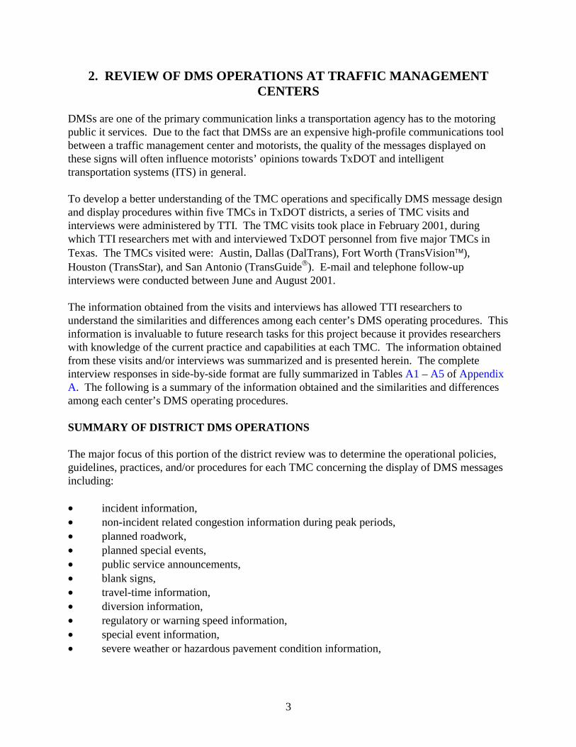
DMSs are one of the primary communication links a transportation agency has to the motoring public it services. Due to the fact that DMSs are an expensive high-profile communications tool between a traffic management center and motorists, the quality of the messages displayed on these signs will often influence motorists’ opinions towards TxDOT and intelligent transportation systems (ITS) in general. To develop a better understanding of the TMC operations and specifically DMS message design and display procedures within five TMCs in TxDOT districts, a series of TMC visits and interviews were administered by TTI. The TMC visits took place in February 2001, during which TTI researchers met with and interviewed TxDOT personnel from five major TMCs in Texas. The TMCs visited were: Austin, Dallas (DalTrans), Fort Worth (TransVision), Houston (TransStar), and San Antonio (TransGuide). E-mail and telephone follow-up interviews were conducted between June and August 2001. The information obtained from the visits and interviews has allowed TTI researchers to understand the similarities and differences among each center’s DMS operating procedures. This information is invaluable to future research tasks for this project because it provides researchers with knowledge of the current practice and capabilities at each TMC. The information obtained from these visits and/or interviews was summarized and is presented herein. The complete interview responses in side-by-side format are fully summarized in Tables A1 – A5 of Appendix A. The following is a summary of the information obtained and the similarities and differences among each center’s DMS operating procedures. SUMMARY OF DISTRICT DMS OPERATIONS The major focus of this portion of the district review was to determine the operational policies, guidelines, practices, and/or procedures for each TMC concerning the display of DMS messages including: • incident information, • non-incident related congestion information during peak periods, • planned roadwork, • planned special events, • public service announcements, • blank signs, • travel-time information, • diversion information, • regulatory or warning speed information, • special event information, • severe weather or hazardous pavement condition information,

4
• advertisements, and • inter-modal information.
Information obtained from the TMC visits and interviews regarding DMS operations is summarized in Tables A1 – A5 of Appendix A. Portions of these tables have been condensed further and are included in the text in Tables 1 – 4. Similarities and differences among the TMCs regarding general TMC operations and DMS message display practices, based on the answers provided by TxDOT district personnel, are presented in the sections that follow. Comparison of DMS Operations DMS Policy and Guidelines To ensure that messages are uniformly designed and operated, the TMCs should have an established policy or a set of guidelines concerning the practices and procedures of designing and displaying DMS messages. Currently none of the five TMCs surveyed operate DMSs under an established written policy. Four of the five TMCs (Dallas, Fort Worth, Houston, and San Antonio), however, do follow a set of written guidelines for design and display of DMS messages. The guidelines, which vary in detail from a set of memorandums to procedural manuals, are intended to provide the DMS operators with a set of procedures to follow when posting messages. However, they do not provide the level of operational consistency that a DMS message policy or standard would establish. The level of detail of the guidelines appears to be directly proportional to the size of the TMC and the area under surveillance. The smaller TMCs (Austin and Dallas) have few or no guidelines to follow, while the larger TMCs (Fort Worth, Houston, and San Antonio) use DMS operations manuals that include message design and display procedures. It should be pointed out, however, that very few inter-district or statewide operating guidelines exist within TxDOT, which leads each TMC to, in many ways, operate autonomously from the others. As the number of districts with TMCs continues to increase throughout Texas, providing consistent use of DMSs among districts will become increasingly important. DMS Messages for Incidents Incident messages are generally regarded by transportation agencies nationwide as the highest priority messages for posting on DMSs. This is certainly the case within TxDOT. Each district surveyed considers incident-related messages to be the highest priority message and posts such messages accordingly. This high priority is based on the safety and congestion implications that arise when incidents occur compared to normal or recurring congestion. When competing incidents arise, districts either give priority to the upstream incident or make decisions based on competing scenarios as they arise. Although all TMCs consider incident-related messages to be the highest priority, there is much variability among the districts in the way that incidents are detected, the design of the incident messages, and the way that the incident messages are posted. The incident messaging practices of each district surveyed are presented in Table 1.
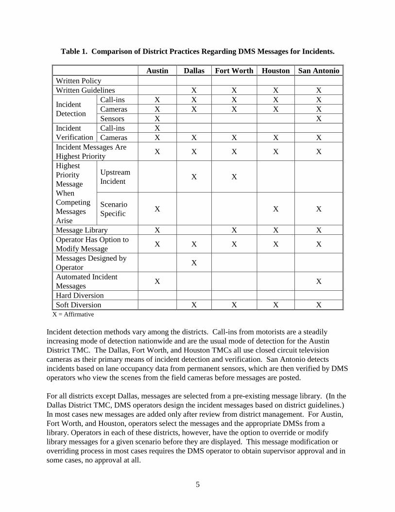
5
Table 1. Comparison of District Practices Regarding DMS Messages for Incidents.
Austin Dallas Fort Worth Houston San Antonio Written Policy Written Guidelines X X X X
Call-ins X X X X X Cameras X X X X X
Incident Detection
Sensors X X Call-ins X Incident
Verification Cameras X X X X X Incident Messages Are Highest Priority
X X X X X
Upstream Incident
X X
Highest Priority Message When Competing Messages Arise
Scenario Specific
X X X
Message Library X X X X Operator Has Option to Modify Message
X X X X X
Messages Designed by Operator
X
Automated Incident Messages
X X
Hard Diversion Soft Diversion X X X X
X = Affirmative Incident detection methods vary among the districts. Call-ins from motorists are a steadily increasing mode of detection nationwide and are the usual mode of detection for the Austin District TMC. The Dallas, Fort Worth, and Houston TMCs all use closed circuit television cameras as their primary means of incident detection and verification. San Antonio detects incidents based on lane occupancy data from permanent sensors, which are then verified by DMS operators who view the scenes from the field cameras before messages are posted. For all districts except Dallas, messages are selected from a pre-existing message library. (In the Dallas District TMC, DMS operators design the incident messages based on district guidelines.) In most cases new messages are added only after review from district management. For Austin, Fort Worth, and Houston, operators select the messages and the appropriate DMSs from a library. Operators in each of these districts, however, have the option to override or modify library messages for a given scenario before they are displayed. This message modification or overriding process in most cases requires the DMS operator to obtain supervisor approval and in some cases, no approval at all.
6
The San Antonio District TMC has a highly automated message and sign selection process for incident signing including a large database of preset incident scenarios. These incident scenarios include appropriate messages and signs on which they should be displayed. Scenarios are generated from the database based on lane occupancy data algorithms and simple inputs from the DMS operator as to the nature of the incident. The operator verifies the incident and previews the scenario on the computer screen before the messages are sent out. Operators may modify messages, but only with approval from an operations supervisor. A written incident management plan is currently being developed for TransGuide. Houston already has an incident traffic management plan for the I-10 corridor consisting of a detour plan and team to respond to major incidents with placement of static detour signs. One incident-related DMS message practice that is constant among the five TMCs surveyed is that none of the TMCs post hard diversion messages (messages with a specific alternative route) for any type of incident. (Houston and Dallas often use hard diversion in cases where there is a major closure due to construction.) Many districts cited jurisdictional and political issues that inhibit them from posting hard diversion messages. All districts except Austin do use soft diversion messages (non-specific suggestion to use alternative routes) often as the second frame of a two-frame incident message. Soft diversion messages have an intentionally lessened effect on freeway traffic diversion. Although it is generally avoided nationwide, hard diversion if used properly may work to balance the traffic demand over the roadway network surrounding a major incident. In a 1998 study of TMC diversion messaging practices in the U.S., Durkop (1) found that most agencies do not display hard diversion messages due to one or more of the following factors: • lack of roadway capacity on the surrounding network, • lack of traffic management capabilities on the diversion roadways, • lack of traffic management coordination between agencies, or • lack of alternative routes on which to divert. In addition, motorist compliance and safety issues pertaining to hard diversion are other factors working against its use. DMS Messages for Non-Incidents Major discrepancies exist among the districts’ DMS operating procedures when no incidents have occurred during both the peak and off-peak hours. In 1996, TxDOT Traffic Operations Division developed a set of guidelines for DMS message posting for non-incident related messages that were distributed to district personnel in each of the TMCs in Texas (2). This memorandum was developed by TxDOT Traffic Operations staff through consultation with traffic management specialists. It contained a list of the following advantages and disadvantages of leaving the DMS blank in the absence of incidents or roadwork: Advantages: • energy cost savings, • maintenance cost savings,
7
• motorists are not subjected to information overload, and • when a message is displayed, it will attract the motorist’s attention.
Disadvantages: • perceived waste of taxpayers’ money and • motorists’ perception that the DMS is malfunctioning or not operating.
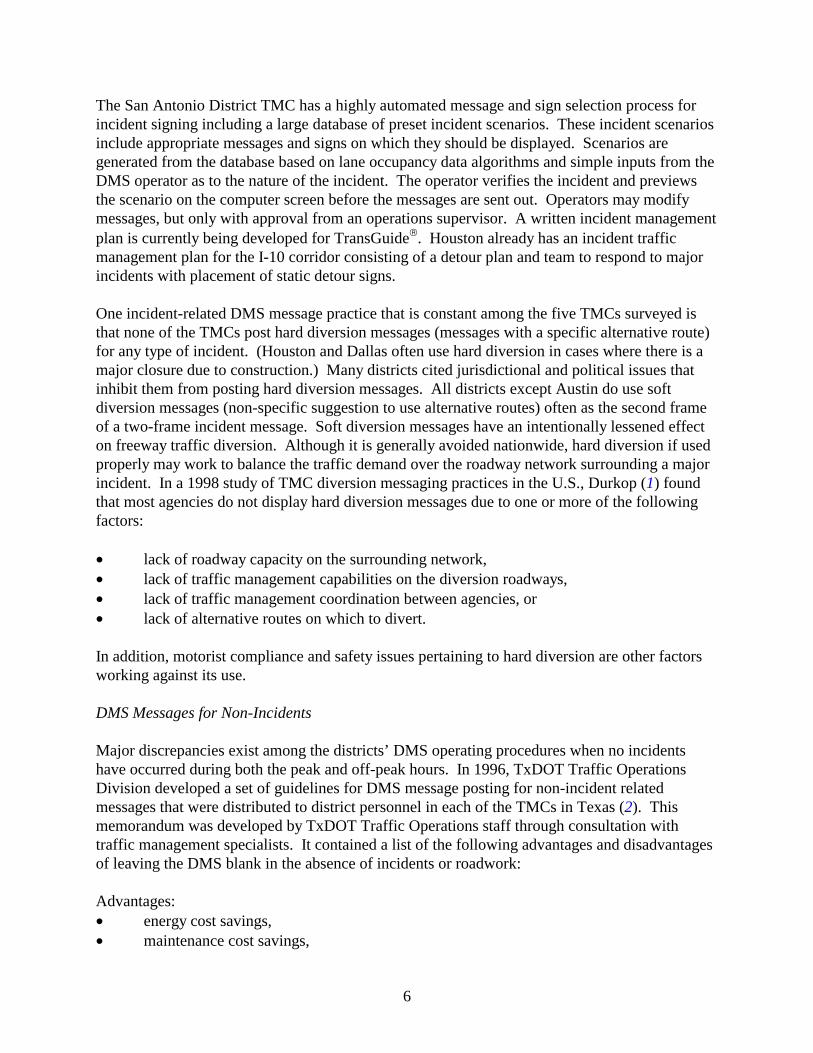
Included in this memorandum was a flowchart for DMS operations under non-incident management conditions. This flowchart is shown in Figure 1. The flowchart clearly suggests that non-incident related messages should be avoided unless they are warranted. The flowchart was developed prior to two districts (Houston and San Antonio) developing the capability for measuring and displaying travel-time information. Information about travel time is very useful to motorists and provides the district the opportunity to display information in the absence of incidents or roadwork. Table 2 provides a comparison of district practices for posting of non-incident related messages.
Figure 1. TxDOT Guidelines for Posting Non-Incident DMS Messages (2).
Will message impact the operations of the freeway corridor?
Will message be relevant to majority of
the drivers?
Will message have a defined time of use?
Will message be used for a short-term
duration?
Message may be displayed.
Consider using alternative signing
method.
DO NOT DISPLAY
Yes
Yes
Yes
Yes
No
No
No
No

8
Table 2. Comparison of District Practices Regarding DMS Messages for Non-Incidents.
Austin Dallas Fort Worth Houston San Antonio Written Policy Written Guidelines X X X X
“Congestion” X Travel Time X X Manually Entered
X
Non-Incident Related Congestion Messages Automated X X Planned Roadwork X X X X X Planned Special Events X X X X Public Service Announcements
X X X X X
Avoid Blank Signs
X X
Blank Signs Blank Unless Message Warranted
X X X
Speed Messages Advertisements Inter-modal Information X Severe Weather or Hazardous Pavement Conditions
X X X X
X = Affirmative As previously stated, district personnel are divided as to the use of non-incident related messages, especially when no prudent message is warranted. For example, two districts (Houston and San Antonio) attempt to have messages posted on the DMSs at all times to avoid a potential negative public perception that is sometimes associated with blank signs. For one district (Houston), avoidance of blank signs is such a high priority that time of day messages may be posted. While avoidance of blank signs may work to eliminate the potential negative public perception, the effect on traffic safety is not well known. The other three TMCs that were interviewed (Austin, Dallas, and Fort Worth) follow the previously referenced TxDOT memorandum and leave signs blank unless a message is warranted. Guidelines as to the types of non-incident messages that may be posted vary among districts, as well. All districts post messages pertaining to planned roadwork, assuming that sufficient notice is given. Roadwork messages are usually the second highest priority message type, although portable DMSs are often provided in the vicinity for dedicated support of roadwork activities. Another high priority message type for those districts that possess traffic flow sensing capabilities is that of non-incident related congestion or travel-time information. These types of messages are used to inform motorists about normal or recurring congestion during both the peak

9
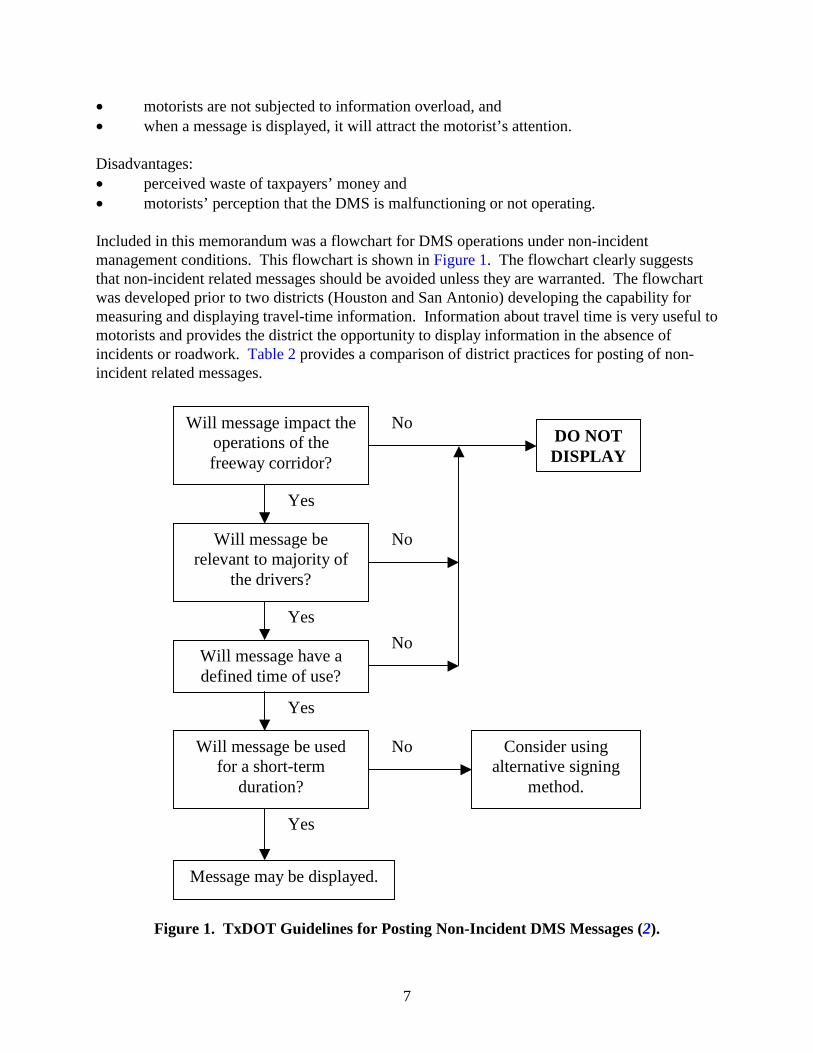
and off-peak periods and in some cases are posted automatically. These automated messages are overridden by incident or construction information when the need arises. Each of the three districts that have traffic-sensing capabilities (Fort Worth, Houston, and San Antonio) display non-incident related congestion messages, but each displays such messages in a different way. Fort Worth TransVision displays automated information as to the level of congestion based on loop detector data. Houston TranStar displays manually entered travel-time information based on automatic vehicle identification (AVI) data; however, because of the manual data entry, these messages often get neglected during the peak period due to the large number of incidents that occur. San Antonio’s TransGuide utilizes the most advanced traffic detection and automated travel-time display of any TMC in Texas. Travel time ranges to landmarks or other highways are automatically displayed (based on detector data, average speed per segment) and are the default messages during the day. Major incidents will completely override travel-time messages, while minor incidents will include an incident message frame split with an automated travel-time frame. Four of the five districts (Dallas, Fort Worth, Houston, and San Antonio) also post messages for large planned special events. Because many of these special events occur on weekends or holidays, interference with normal weekday commuter traffic messaging is often avoided. Public service announcements are also allowed by all of the districts, provided that the district approves the messages. These messages are usually restricted to traffic safety or air pollution related messages. It should be noted that under no circumstances do any of the districts allow advertisements to be posted on their DMSs. Regulatory or warning speed messages are also not posted on permanent DMSs in any of the TMCs. (Speed-related messages are often placed on portable DMSs in construction zones.) Severe weather or hazardous pavement condition messages are posted by four of the five TMCs that were interviewed (Dallas, Fort Worth, Houston, and San Antonio). Most of these messages pertain to pavement/weather conditions involving flooding or ice on the roadway. The districts generally do not post messages pertaining to inter-modal information, except in Houston where park-and-ride information for special event traffic is posted. Other Message Posting Practices To fully describe the use of DMS messages within the districts, one must consider not only the content of the message, but also the characteristics of the message when it is placed. Table 3 provides a comparison of the district practices regarding message characteristics. All districts use two-frame messages with varying exposure times (average of two seconds per frame) when long messages are needed. Three districts (Dallas, Fort Worth, and Houston) also change one line of a message while leaving the other two static in situations where a certain subject of the message is to be emphasized, such as the specific message audience. It should be noted that based on recent findings from TxDOT Project 0-1882, TTI researchers recommended that this approach not be used because it takes drivers longer to read the message (3). Flashing messages or certain lines within messages is practiced only in the Fort Worth District and only in situations that are determined to be significant, but not urgent enough to use flashing beacons. It should be noted that recent results from TxDOT Project 0-1882 showed that it takes drivers
10
longer to read flashing messages. TTI researchers recommended that flashing messages not be used (3). Flashing beacons are used by all districts although warrants for their use vary, usually involving messages pertaining to driver safety or the ability to avoid substantial delay, such as for major incidents or construction.
Table 3. Comparison of District Practices Regarding DMS Message Characteristics.
Austin Dallas Fort Worth Houston San Antonio Written Policy Written Guidelines X X X X Two-Frame Messages X X X X X Changing Only Specific Lines in Two-Frame Messages
X X X
Flashing Messages or Lines X Beacons X X X X X
Allowed by District
X X Message Posting by Other Agencies
Message Library Used
X X
Message Modification for Local Conditions
X X X
X = Affirmative Message posting on TxDOT-owned DMSs by agencies other than TxDOT is a very uncommon practice, although it is allowed by the Houston District for use by the Houston Metro transit authority on DMSs in the high-occupancy vehicle (HOV) lanes and park-and-ride lots; and by the Austin District for use by the city law enforcement agency during after-hours. In each case, a message library is recommended for use. Occasionally DMSs have been placed in locations where the message legibility distance is reduced. Such locations include DMS placement at extreme horizontal and vertical curves, overpasses and locations where glare from the sun is common. For these cases, message length and content should be reduced to accommodate for the reduction in readability distance. Three districts (Austin, Houston, and San Antonio) make such modifications to DMS messages. Message Posting Procedures on Portable DMSs While the district messaging practices on permanent DMSs generally follow the established district operating guidelines, messaging practices on portable DMSs are entirely different. The control of portable DMS messaging while in TxDOT right-of-way is an issue of great importance and applies to all districts, not just to those districts with TMCs. Portable DMSs may either be state owned or privately owned. TxDOT-owned portable DMSs are used extensively for maintenance activities and short-term work zones and occasionally for special events and support of permanent DMSs for major incidents. Privately owned DMSs are generally used in and

11
around construction work zones. Table 4 provides a comparison of the district practices concerning the use of portable DMSs.
Table 4. Comparison of District Practices Regarding Portable DMS Messages.
Austin Dallas Fort Worth Houston San Antonio Construction X X X X X Maintenance X X Special Events X X X X
When Used
Incident Support X X X Controlled From TMC (State-Owned DMS Only)
X
Messages Designed by TMC (State-Owned DMS Only)
X X X
TMC Not Involved with Portable DMS Messages
X X
X = Affirmative The major issue at hand is not who owns the portable DMS, but rather who is responsible for designing and placing the messages that are used. Although they are only for temporary use, portable DMSs must still maintain the same message integrity as the permanent DMSs and should be programmed and placed accordingly. Ideally, all portable DMSs would be controlled and monitored from a TMC. However, portable DMSs pose problems because they are easily moved and are often placed outside of the surveillance or sensor boundaries. These issues make it difficult for the TMC personnel to monitor both the location of the sign and the messages placed, and therefore TMCs either rely heavily on field personnel to monitor the messages or choose to assign control of the portable DMSs to other offices. Due to the difficulties associated with control of portable DMSs, only San Antonio TransGuide controls its portable DMSs from the TransGuide control room. Messages are designed at TransGuide based on the scenario and are generally chosen from the message library. Messages are posted on portable DMSs with the approval of the floor manager, although field personnel assist heavily in assuring that the messages are updated with changing site conditions. The Dallas and Houston districts design the messages based on input from the requesting agency and program the state-owned portable DMSs at the TMC. TxDOT TMCs are not, however, involved with the message design and posting on privately owned portable DMSs used in construction sites. These responsibilities lie with the TxDOT area office project staff, such as the inspector or project engineer, to approve the messages. Occasionally, other agencies, such as the local transit authority, will place portable DMSs on state right-of-way. In these cases, the owning agency is required to obtain permission and message approval through the office of the District Transportation Operations Engineer. The Fort Worth and Austin District TMCs are not involved with the design and control of portable DMS messages.

12
CONCLUSIONS The TxDOT TMC reviews have assisted the researchers in identifying the similarities and differences in the message posting practices of the TMCs and the automated message posting capabilities of each. Some of the main points from the TMC visits regarding DMS operations are as follows: • DMS message posting procedures vary widely from district to district. • No TxDOT TMC currently operates under a written policy for posting of DMS messages. • Four of five TxDOT TMCs operate under a written set of operating guidelines. • No TxDOT TMC uses hard diversion for incidents although soft diversion is used by
most. • Advanced traffic-sensing capabilities exist in the Fort Worth, Houston, and San Antonio
Districts. • Automated message-posting capabilities currently exist in the Fort Worth and San
Antonio TMCs.
The information gained from the TMC reviews will provide valuable information for upcoming tasks in this project and shall be used accordingly to assist in the development of a standardized operators manual and automated messaging system prototype for TxDOT. The detailed results of the TxDOT TMC reviews are reported in Appendix A Tables A1 – A5.

13
3. DECISION FLOWCHARTS AND MODELS In this chapter, the logic and procedure for the design of DMS messages when incidents and roadwork occur are presented in the DMS Message Design Flowchart for Incidents and DMS Message Design Flowchart for Roadwork, respectively. Time-tested DMS message design principles were used in the development of these DMS message design processes. As a prelude to the use of the DMS message design flowcharts, some basic DMS message design principles are provided in the following section. SOME DMS MESSAGE DESIGN PRINCIPLES To be effective, a DMS must communicate a meaningful message that can be read and comprehended by motorists within a very short period. To accomplish this task, the following message design factors should be considered: • content – the specific information displayed, • length – number of words or characters and spaces, • load – number of units of information in message, and • format – order and arrangement of the units of information. Message Content The essential elements to message content are: what is wrong ahead, where is the problem located, and what action the motorist should take. Thus, the content must provide information relative to the motorists’ needs. Motorists expect the problem or reason to appear first, followed by where the problem occurs. Advice, such as “use other routes,” should be presented at the end of the brief message. In urban areas where the crossroads are relatively close and the motorists are familiar with the area, the location of the problem should be referenced to a crossroad, ramp, or landmark. In contrast, motorists who are unfamiliar with the area prefer to have the problem referenced in terms of distance from the DMS. In rural areas where crossroads are infrequent, it becomes necessary to reference the location of the problem in terms of distance even for familiar motorists. When motorists are advised by the DMS message to divert and take a specific highway or route, it is essential that the destination names and routes used in the message are the same as those displayed on the existing guide signs. Inconsistency between the DMS message and the existing guide signs will lead to motorist confusion and may cause some motorists to take incorrect routes. Therefore, the message designer must have a full knowledge of the wording and route markers on the existing guide signs before diversion messages directing motorists to a specific highway or route are used in a DMS message.

14
Message Length The maximum length of a DMS message is controlled in part by the reading time – the time the motorist has available to read the message. Thus, the entire message must be short enough to allow motorists to glance at the sign, read, and comprehend the sign while attending to the complex driving environment. Below are some of the items that need to be considered when determining message length: • It takes unfamiliar motorists longer to read a DMS message than familiar motorists who
see the sign regularly. • Motorists time-share their attention to the roadway and traffic with reading signs. • Motorists must read the entire message on a DMS to obtain relevant information. • There is evidence that an eight-word message (excluding prepositions) is approaching the
processing limits of motorists traveling at speeds of 55 mph or more. • It takes motorists longer to read: 1) flashing messages, 2) messages in which one of the
lines is flashed, and 3) alternating text on one line of a three-line CMS while keeping the other two lines of text the same.
Message Load An informational unit refers to each separate data item given in a message which a motorist could recall and which could be a basis for making a decision. The following example serves to illustrate the concept of units of information: Question 1. What happened? 2. Where? 3. What and how many lanes are affected? 4. What is the effect on traffic? 5. Who is the audience for action statement? 6. What action should motorists take?
Answer 1. Accident 2. At Exit 45 3. Left Lane Closed 4. Major Delay 5. Galveston Traffic 6. Use Loop 610
Informational Units 1 unit 1 unit 1 unit 1 unit 1 unit 1 unit
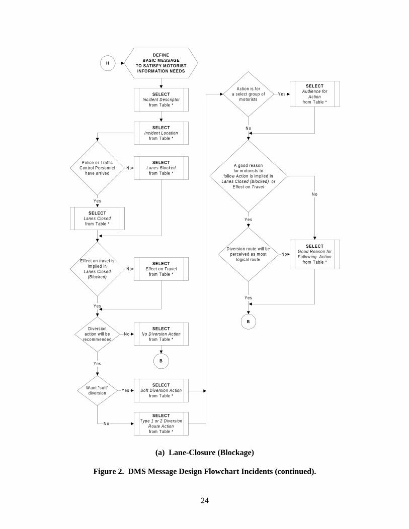
Research and experience (4, 5) have shown that on urban freeways, DMS messages must not exceed four units of information when the freeway operating speed is greater than 35 mph. When speeds are equal to or less than 35 mph, no more than five units should be displayed on a single DMS. The Basic DMS Message is the totality of information that the motorists will need on the DMS in order to make a rational driving decision and consists of the following message elements: • incident or roadwork descriptor, • incident or closure location, • lanes affected or closed, • effect on travel, • action,

15
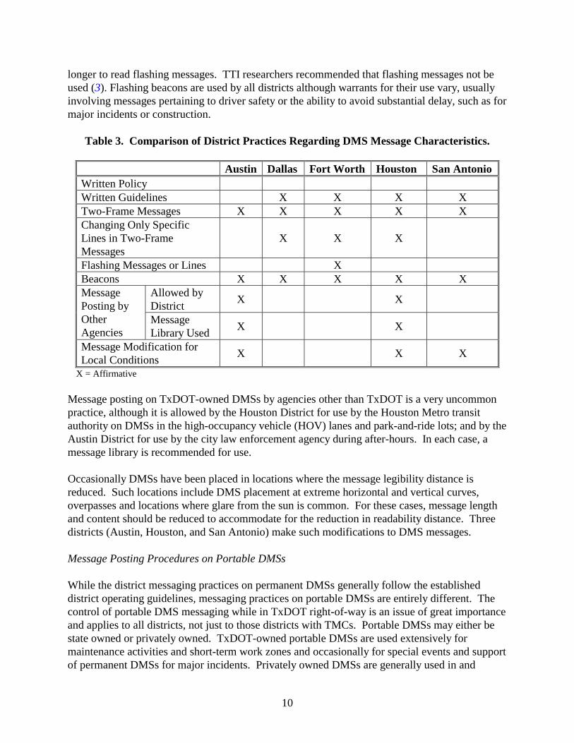
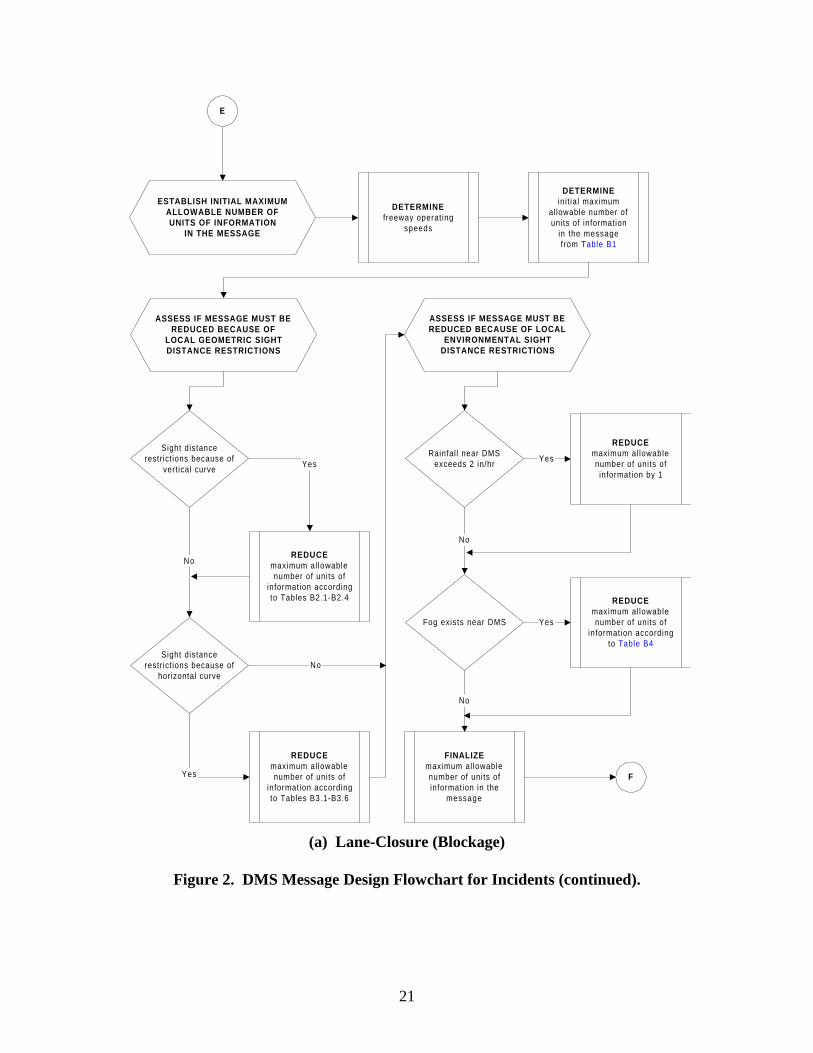
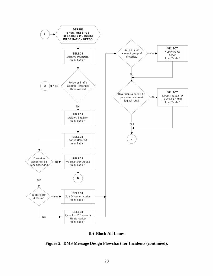
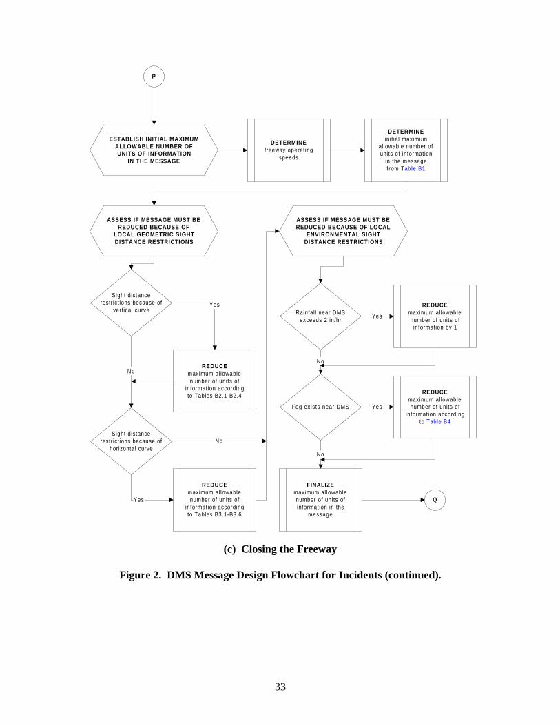
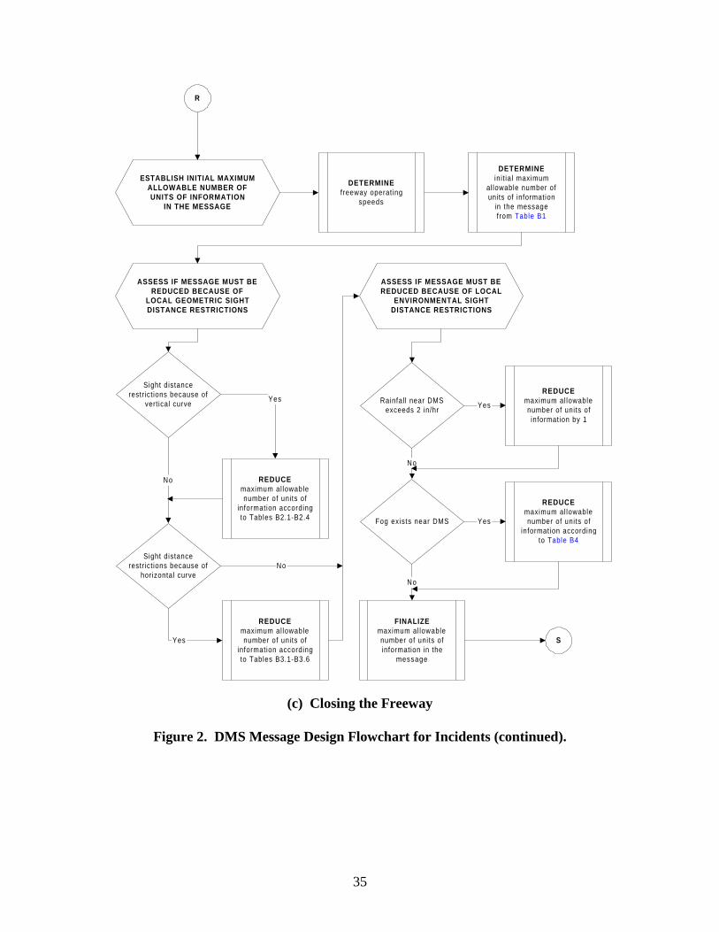
• audience for action, and • one good reason for following action statement. However, in most cases the Basic DMS Message will exceed the informational unit maximum of four or five units. Therefore, priorities must be set to ensure that the most relevant information is displayed, albeit sub-optimal. Message Format The order and arrangement of the units of information is important to allow motorists to easily read and interpret the information and make rational decisions based on that information. Placement of message elements on the wrong line or in the wrong sequence will result in driver confusion and will increase message reading times. In many cases, messages are too long to display at one time. Therefore, the message must be divided into two parts and displayed on two frames. In no case, should the message be longer than what can be displayed on two frames. Each message frame must be cohesive and understandable, and the information units on a specific frame must be compatible. When a specific unit of information does not fit on a DMS line because of the limitation in the number of characters that can be displayed on a line, it sometimes becomes necessary to use abbreviations. Some abbreviations take longer to read and comprehend and thus must be used with care. There is a library of words and phrases of acceptable abbreviations that have been tested via human factors studies in Texas and elsewhere. DMS MESSAGE DESIGN FLOWCHARTS Figure 2 contains the DMS Message Design Flowchart for Incidents while Figure 3 contains the DMS Message Design Flowchart for Roadwork. The user of the DMS message design flow-charts will find a degree of repetition; however, this repetition is necessary to allow the user to reference successive pages when designing a message for the specific DMS location relative to the incident or roadwork. The reference materials for the flowcharts (e.g., tables for each scenario and DMS location) will be created in the second year of the project; thus, currently the table numbers in the flowcharts are denoted with an asterisk. Incidents The DMS Message Design Flowchart for Incidents includes detailed guidelines for the following three scenarios (Figure 2 Part a, b, and c, respectively): 1. lane-closure (blockage) incidents, 2. incidents that block all lanes, and 3. incidents that require closing the freeway.

16
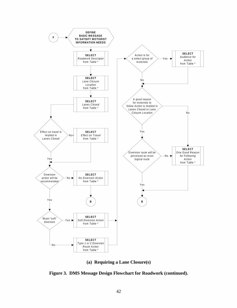
The guidelines are further subdivided with respect to the DMS location: • same freeway and relatively close to the incident, • same freeway but relatively far from the incident, and • a different freeway than the incident. Roadwork The DMS Message Design Flowchart for Roadwork includes detailed guidelines for the following two scenarios (Figure 3 Part a and b, respectively): 1. lane closures and 2. closing the freeway. As with the flowchart for incidents, the guidelines are further subdivided with respect to the DMS location: • same freeway and relatively close to the incident, • same freeway but relatively far from the incident, and • a different freeway than the incident.
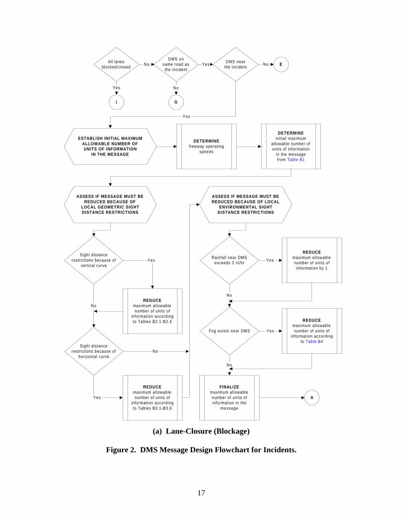
17
EDMS nearthe incident
Yes NoAll lanes
blocked/closed
1
DMS onsame road as
the incident
G
No
No
ESTABLISH INITIAL MAXIMUMALLOWABLE NUMBER OFUNITS OF INFORMATION
IN THE MESSAGE
DETERMINEfreeway operating
speeds
DETERMINEini t ial maximum
allowable number ofunits of information
in the messagefrom Table B1
ASSESS IF MESSAGE MUST BEREDUCED BECAUSE OF
LOCAL GEOMETRIC SIGHTDISTANCE RESTRICTIONS
Sight distancerestrict ions because of
horizontal curve
NoREDUCE
maximum al lowablenumber of units of
information accordingto Tables B2.1-B2.4
REDUCEmaximum al lowablenumber of units of
information accordingto Tables B3.1-B3.6
ASSESS IF MESSAGE MUST BEREDUCED BECAUSE OF LOCAL
ENVIRONMENTAL SIGHTDISTANCE RESTRICTIONS
Rainfal l near DMSexceeds 2 in/hr
Fog exists near DMS
No
REDUCEmaximum al lowablenumber of units ofinformation by 1
Yes
REDUCEmaximum al lowablenumber of units of
information accordingto Table B4
Yes
Yes
Yes
FINALIZEmaximum al lowablenumber of units ofinformation in the
message
No
A
Sight distancerestrict ions because of
vertical curveYes
No
Yes
(a) Lane-Closure (Blockage)
Figure 2. DMS Message Design Flowchart for Incidents.

18
DEFINEBASIC MESSAGE
TO SATISFY MOTORISTINFORMATION NEEDS
SELECTIncident Descriptor
from Table *
SELECTIncident Location
from Table *
SELECTLanes C losedfrom Table *
Effect on travel isim plied in
Lanes C losed(B locked)
SELECTNo D iversion Action
from Table *
SELECTEffect on Travel
from Table *No
D iversionaction will be
recom m ended
Yes
A
W ant "soft"d iversion
No
Yes
SELECTSoft D iversion Ac tion
from Table *
SELECTType 1 or 2 D iversion
Route Actionfrom Table *
Action is fora select group of
m otoris ts
SELECTAudience for
Actionfrom Table *
A good reasonfor m otorists to
fo llow Action is im plied inLanes C losed (B locked) or
Effect on Travel
SELECTGood Reason forFollow ing Action
from Table *
D iversion route will beperceived as m ost
logical route
Yes
No
No
Yes
Yes
B
Yes
No
B
No
Police or TrafficContro l P ersonnel
have arrived
SELECTLanes B locked
from Table *
Yes
No
(a) Lane-Closure (Blockage)
Figure 2. DMS Message Design Flowchart for Incidents (continued).

19
REDUCE THE NUM BER OFM ESSAGE UNITS IF
NECESSARY
Num ber o f un its ofinform ation in Basic
M essage is g reate r thanm axim um allowab le
OM ITInc ident Descripto r
according to guide linesin Section *
CNo
Y es
B
Num ber o f un its ofinform ation in Basic
M essage is g reate r thanm axim um allowab le
C No
M essage conta insm ore than one
A udience fo r Ac tion
Y es
OM ITall but one
A udience fo r Ac tionY es
Num ber o f un its ofinform ation in Basic
M essage is g reate r thanm axim um allowab le
No
COM IT
in form ation according togu ide lines in Tab le *
No
C
Y es
(a) Lane-Closure (Blockage)
Figure 2. DMS Message Design Flowchart for Incidents (continued).

20
ADJUSTM ESSAGE TO FIT ON
EXISTING DM S
FORMAT M ESSAGEaccording toguidelines in
Tables *
FORMATM ESSAGEC
Yes
ADJUST M ESSAGE TOFIT ON 3 LINES OR LESS
SEPARATEm essage e lem ents
according toguidelines in
Sec tion *
SPLITm essage in to 2
fram es according toguidelines in
Sec tion *
3 or fewerdecis ion-relevant
units of in form ation aredisplayed on one
fram e
M essagecan be disp layed
on 3 linesor less
Part o f one m essageelem ent is on the sam eline as part o f a second
m essage e lem ent
OMITin form ation to reduce to 3
decis ion-relevant unitsaccording to gu ide lines in
Sec tion *
Yes
No
No
Yes
Yes
M essage linestoo long
No
ABBREVIATEwords accord ing to
guidelines inSec tion *
Yes
DNo
DM S has4 lines
DM S has3 lines
EndNoNo
YesEntire m essagecan fit on DM S
OMITin form ation accord ing to
guidelines in Tables *No
Yes
FINALIZE DM SM ESSAGE D
REVIEWm essage for
inconsistencies andincom patib ilit ies
M AKEadditional
adjustm ents ifnecessary
ASSESS EFFECTS OFLARGE TRUCKS
DETERM INEif la rge trucks effect the
ability of m otorists to seethe D M S using
Tables *
FINAL DM SM ESSAGE
(a) Lane-Closure (Blockage)
Figure 2. DMS Message Design Flowchart for Incidents (continued).
21
ESTABLISH INITIAL MAXIMUMALLOWABLE NUMBER OFUNITS OF INFORMATION
IN THE MESSAGE
DETERMINEfreeway operating
speeds
DETERMINEini t ial maximum
allowable number ofunits of information
in the messagefrom Table B1
ASSESS IF MESSAGE MUST BEREDUCED BECAUSE OF
LOCAL GEOMETRIC SIGHTDISTANCE RESTRICTIONS
Sight distancerestrict ions because of
horizontal curve
NoREDUCE
maximum al lowablenumber of units of
information accordingto Tables B2.1-B2.4
Yes
REDUCEmaximum al lowablenumber of units of
information accordingto Tables B3.1-B3.6
ASSESS IF MESSAGE MUST BEREDUCED BECAUSE OF LOCAL
ENVIRONMENTAL SIGHTDISTANCE RESTRICTIONS
Rainfal l near DMSexceeds 2 in/hr
Fog exists near DMS
No
REDUCEmaximum al lowablenumber of units ofinformation by 1
Yes
REDUCEmaximum al lowablenumber of units of
information accordingto Table B4
Yes
Yes
FINALIZEmaximum al lowablenumber of units ofinformation in the
message
No
F
Sight distancerestrict ions because of
vertical curve
E
No
(a) Lane-Closure (Blockage)
Figure 2. DMS Message Design Flowchart for Incidents (continued).

22
DEFINEBASIC MESSAGE
TO SATISFY MOTORISTINFORM ATION NEEDS
SELECTInc ident Descriptor
from Table *
SELECTInc ident Location
from Table *
SELECTLanes Closedfrom Table *
Effec t on travel isim plied in
Lanes Closed(B locked)
SELECTNo D ivers ion Action
from Table *
SELECTEffec t on Travel
from Table *No
D ivers ionaction will be
recom m ended
Yes
F
W ant "soft"d iversion
No
Yes
SELECTSoft D ivers ion Action
from Table *
SELECTType 1 or 2 Diversion
Route A ctionfrom Table *
Action is fora select group of
m otorists
SELECTAudience for
Actionfrom Table *
A good reasonfor m otorists to
follow Action is im plied inLanes Closed (B locked) or
Effec t on Travel
SELECTGood Reason forFollow ing Action
from Table *
D ivers ion route will beperceived as m ost
logical route
Yes
No
No
Yes
Yes
B
Yes
No
B
No
Police or TrafficContro l Personnel
have arrived
SELECTLanes B locked
from Table *
Yes
No
(a) Lane-Closure (Blockage)
Figure 2. DMS Message Design Flowchart for Incidents (continued).

23
ESTABLISH INITIAL MAXIMUMALLOWABLE NUMBER OFUNITS OF INFORMATION
IN THE MESSAGE
DETERMINEfreeway operating
speeds
DETERMINEini t ial maximum
allowable number ofunits of information
in the messagefrom Table B1
ASSESS IF MESSAGE MUST BEREDUCED BECAUSE OF
LOCAL GEOMETRIC SIGHTDISTANCE RESTRICTIONS
Sight distancerestrict ions because of
horizontal curve
NoREDUCE
maximum al lowablenumber of units of
information accordingto Tables B2.1-B2.4
Yes
REDUCEmaximum al lowablenumber of units of
information accordingto Tables B3.1-B3.6
ASSESS IF MESSAGE MUST BEREDUCED BECAUSE OF LOCAL
ENVIRONMENTAL SIGHTDISTANCE RESTRICTIONS
Rainfal l near DMSexceeds 2 in/hr
Fog exists near DMS
No
REDUCEmaximum al lowablenumber of units ofinformation by 1
Yes
REDUCEmaximum al lowablenumber of units of
information accordingto Table B4
Yes
Yes
FINALIZEmaximum al lowablenumber of units ofinformation in the
message
No
H
Sight distancerestrict ions because of
vertical curve
G
No
(a) Lane-Closure (Blockage)
Figure 2. DMS Message Design Flowchart for Incidents (continued).
24
DEFINEBASIC MESSAGE
TO SATISFY MOTORISTINFORM ATION NEEDS
SELECTInc ident Descriptor
from Table *
SELECTInc ident Location
from Table *
SELECTLanes Closedfrom Table *
Effec t on travel isim plied in
Lanes Closed(B locked)
SELECTNo D ivers ion Action
from Table *
SELECTEffec t on Travel
from Table *No
D ivers ionaction will be
recom m ended
Yes
H
W ant "soft"d iversion
No
Yes
SELECTSoft D ivers ion Action
from Table *
SELECTType 1 or 2 Diversion
Route A ctionfrom Table *
Action is fora select group of
m otorists
SELECTAudience for
Actionfrom Table *
A good reasonfor m otorists to
follow Action is im plied inLanes Closed (B locked) or
Effec t on Travel
SELECTGood Reason forFollow ing Action
from Table *
D ivers ion route will beperceived as m ost
logical route
Yes
No
No
Yes
Yes
B
Yes
No
B
No
Police or TrafficContro l Personnel
have arrived
SELECTLanes B locked
from Table *
Yes
No
(a) Lane-Closure (Blockage)
Figure 2. DMS Message Design Flowchart Incidents (continued).

25
KDMS near
the incidentNo1
DMS onsame road as
the incident
M
No
ESTABLISH INITIAL MAXIMUMALLOWABLE NUMBER OFUNITS OF INFORMATION
IN THE MESSAGE
DETERMINEfreeway operating
speeds
DETERMINEini t ial maximum
allowable number ofunits of information
in the messagefrom Table B1
ASSESS IF MESSAGE MUST BEREDUCED BECAUSE OF
LOCAL GEOMETRIC SIGHTDISTANCE RESTRICTIONS
Sight distancerestrict ions because of
horizontal curve
NoREDUCE
maximum al lowablenumber of units of
information accordingto Tables B2.1-B2.4
Yes
REDUCEmaximum al lowablenumber of units of
information accordingto Tables B3.1-B3.6
ASSESS IF MESSAGE MUST BEREDUCED BECAUSE OF LOCAL
ENVIRONMENTAL SIGHTDISTANCE RESTRICTIONS
Rainfal l near DMSexceeds 2 in/hr
Fog exists near DMS
No
REDUCEmaximum al lowablenumber of units ofinformation by 1
Yes
REDUCEmaximum al lowablenumber of units of
information accordingto Table B4
Yes
No
Yes
Yes
FINALIZEmaximum al lowablenumber of units ofinformation in the
message
No
J
Sight distancerestrict ions because of
vertical curve
Police or TrafficControl Personnel
have arr ived
2
No YesNo
Yes
(b) Block All Lanes
Figure 2. DMS Message Design Flowchart for Incidents (continued).

26
DEFINEBASIC M ESSAGE
TO SATISFY M OTORISTINFORM ATION NEEDS
SELECTInc iden t D esc rip tor
from Tab le *
SELECTInc iden t Location
from Tab le *
SELECTLanes B locked
from Tab le *
SELECTN o D ivers ion A ction
from Tab le *
D ivers ionac tion w ill be
recom m ended
J
W ant "so ft"d ive rs ion
N o
Y es
SELECTS oft D ive rs ion A c tion
from Tab le *
SELECTType 1 o r 2 D ivers ion
R ou te A ctionfrom Tab le *
A ction is fora se lec t group of
m otoris ts
SELECTA ud ience for
A ctionfrom Tab le *
SELECTG ood R eason forFollow ing A ction
from Tab le *
D ivers ion route w ill beperce ived as m ost
log ica l routeN o
Y es
Y es
B
Y es
N o
B
N o
P olice or T rafficC on tro l P e rsonne l
H ave A rrived2 Y es
N o
(b) Block All Lanes
Figure 2. DMS Message Design Flowchart for Incidents (continued).

27
ESTABLISH INITIAL MAXIMUMALLOWABLE NUMBER OFUNITS OF INFORMATION
IN THE MESSAGE
DETERMINEfreeway operating
speeds
DETERMINEini t ial maximum
allowable number ofunits of information
in the messagefrom Table B1
ASSESS IF MESSAGE MUST BEREDUCED BECAUSE OF
LOCAL GEOMETRIC SIGHTDISTANCE RESTRICTIONS
Sight distancerestrict ions because of
horizontal curve
NoREDUCE
maximum al lowablenumber of units of
information accordingto Tables B2.1-B2.4
Yes
REDUCEmaximum al lowablenumber of units of
information accordingto Tables B3.1-B3.6
ASSESS IF MESSAGE MUST BEREDUCED BECAUSE OF LOCAL
ENVIRONMENTAL SIGHTDISTANCE RESTRICTIONS
Rainfal l near DMSexceeds 2 in/hr
Fog exists near DMS
No
REDUCEmaximum al lowablenumber of units ofinformation by 1
Yes
REDUCEmaximum al lowablenumber of units of
information accordingto Table B4
Yes
No
Yes
FINALIZEmaximum al lowablenumber of units ofinformation in the
message
No
L
Sight distancerestrict ions because of
vertical curve
K
(b) Block All Lanes
Figure 2. DMS Message Design Flowchart for Incidents (continued).
28
DEFINEBASIC M ESSAGE
TO SATISFY M OTORISTINFORM ATION NEEDS
SELECTInc iden t D esc rip tor
from Tab le *
SELECTInc iden t Location
from Tab le *
SELECTLanes B locked
from Tab le *
SELECTN o D ivers ion A ction
from Tab le *
D ivers ionac tion w ill be
recom m ended
L
W ant "so ft"d ive rs ion
N o
Y es
SELECTS oft D ive rs ion A c tion
from Tab le *
SELECTType 1 o r 2 D ivers ion
R ou te A ctionfrom Tab le *
A ction is fora se lec t group of
m otoris ts
SELECTA ud ience for
A ctionfrom Tab le *
SELECTG ood R eason forFollow ing A ction
from Tab le *
D ivers ion route w ill beperce ived as m ost
log ica l routeN o
Y es
Y es
B
Y es
N o
B
N o
P olice or T rafficC on tro l P e rsonne l
H ave A rrived2 Y es
N o
(b) Block All Lanes
Figure 2. DMS Message Design Flowchart for Incidents (continued).

29
ESTABLISH INITIAL MAXIMUMALLOWABLE NUMBER OFUNITS OF INFORMATION
IN THE MESSAGE
DETERMINEfreeway operating
speeds
DETERMINEini t ial maximum
allowable number ofunits of information
in the messagefrom Table B1
ASSESS IF MESSAGE MUST BEREDUCED BECAUSE OF
LOCAL GEOMETRIC SIGHTDISTANCE RESTRICTIONS
Sight distancerestrict ions because of
horizontal curve
No REDUCEmaximum al lowablenumber of units of
information accordingto Tables B2.1-B2.4
Yes
REDUCEmaximum al lowablenumber of units of
information accordingto Tables B3.1-B3.6
ASSESS IF MESSAGE MUST BEREDUCED BECAUSE OF LOCAL
ENVIRONMENTAL SIGHTDISTANCE RESTRICTIONS
Rainfal l near DMSexceeds 2 in/hr
Fog exists near DMS
No
REDUCEmaximum al lowablenumber of units ofinformation by 1
Yes
REDUCEmaximum al lowablenumber of units of
information accordingto Table B4
Yes
No
Yes
FINALIZEmaximum al lowablenumber of units ofinformation in the
message
No
N
Sight distancerestrict ions because of
vertical curve
M
(b) Block All Lanes
Figure 2. DMS Message Design Flowchart for Incidents (continued).

30
DEFINEBASIC M ESSAGE
TO SATISFY M OTORISTINFORM ATION NEEDS
SELECTInc iden t D esc rip tor
from Tab le *
SELECTInc iden t Location
from Tab le *
SELECTLanes B locked
from Tab le *
SELECTN o D ivers ion A ction
from Tab le *
D ivers ionac tion w ill be
recom m ended
N
W ant "so ft"d ive rs ion
N o
Y es
SELECTS oft D ive rs ion A c tion
from Tab le *
SELECTType 1 o r 2 D ivers ion
R ou te A ctionfrom Tab le *
A ction is fora se lec t group of
m otoris ts
SELECTA ud ience for
A ctionfrom Tab le *
SELECTG ood R eason forFollow ing A ction
from Tab le *
D ivers ion route w ill beperce ived as m ost
log ica l routeN o
Y es
Y es
B
Y es
N o
B
N o
P olice or T rafficC on tro l P e rsonne l
H ave A rrived2 Y es
N o
(b) Block All Lanes
Figure 2. DMS Message Design Flowchart for Incidents (continued).

31
PDMS near
the incidentYes No2
DMS onsame road as
the incident
R
No
ESTABLISH INITIAL MAXIMUMALLOWABLE NUMBER OFUNITS OF INFORMATION
IN THE MESSAGE
DETERMINEfreeway operating
speeds
DETERMINEini t ial maximum
allowable number ofunits of information
in the messagefrom Table B1
ASSESS IF MESSAGE MUST BEREDUCED BECAUSE OF
LOCAL GEOMETRIC SIGHTDISTANCE RESTRICTIONS
Sight distancerestrict ions because of
horizontal curve
NoREDUCE
maximum al lowablenumber of units of
information accordingto Tables B2.1-B2.4
Yes
REDUCEmaximum al lowablenumber of units of
information accordingto Tables B3.1-B3.6
ASSESS IF MESSAGE MUST BEREDUCED BECAUSE OF LOCAL
ENVIRONMENTAL SIGHTDISTANCE RESTRICTIONS
Rainfal l near DMSexceeds 2 in/hr
Fog exists near DMS
No
REDUCEmaximum al lowablenumber of units ofinformation by 1
Yes
REDUCEmaximum al lowablenumber of units of
information accordingto Table B4
Yes
No
Yes
Yes
FINALIZEmaximum al lowablenumber of units ofinformation in the
message
No
O
Sight distancerestrict ions because of
vertical curve
No
(c) Closing the Freeway
Figure 2. DMS Message Design Flowchart for Incidents (continued).

32
DEFINEBASIC M ESSAGE
TO SATISFY M OTORISTINFORM ATION NEEDS
SELECTInc iden t D esc rip tor
from Tab le *
SELECTInc iden t Location
from Tab le *
SELECTLanes C losedfrom Tab le *
SELECTType 1, 2 , 3 , or 4D ivers ion A ction
from Tab le *
D ivers ion tra fficcontro l is in p lace
O
N o
SELECTType 5 D ivers ion
A ctionfrom Tab le *
A ction is fora se lec t group of
m otoris ts
SELECTA ud ience for
A ctionfrom Tab le *
SELECTG ood R eason forFollow ing A ction
from Tab le *
D ivers ion route w ill beperce ived as m ost
log ica l routeN o
Y es
Y es
B
N o
SELECTC losure Location
from Tab le *
Y es
(c) Closing the Freeway
Figure 2. DMS Message Design Flowchart for Incidents (continued).
33
ESTABLISH INITIAL MAXIMUMALLOWABLE NUMBER OFUNITS OF INFORMATION
IN THE MESSAGE
DETERMINEfreeway operating
speeds
DETERMINEini t ial maximum
allowable number ofunits of information
in the messagefrom Table B1
ASSESS IF MESSAGE MUST BEREDUCED BECAUSE OF
LOCAL GEOMETRIC SIGHTDISTANCE RESTRICTIONS
Sight distancerestrict ions because of
horizontal curve
NoREDUCE
maximum al lowablenumber of units of
information accordingto Tables B2.1-B2.4
Yes
REDUCEmaximum al lowablenumber of units of
information accordingto Tables B3.1-B3.6
ASSESS IF MESSAGE MUST BEREDUCED BECAUSE OF LOCAL
ENVIRONMENTAL SIGHTDISTANCE RESTRICTIONS
Rainfal l near DMSexceeds 2 in/hr
Fog exists near DMS
No
REDUCEmaximum al lowablenumber of units ofinformation by 1
Yes
REDUCEmaximum al lowablenumber of units of
information accordingto Table B4
Yes
No
Yes
FINALIZEmaximum al lowablenumber of units ofinformation in the
message
No
Q
Sight distancerestrict ions because of
vertical curve
P
(c) Closing the Freeway
Figure 2. DMS Message Design Flowchart for Incidents (continued).

34
DEFINEBASIC M ESSAGE
TO SATISFY M OTORISTINFORM ATION NEEDS
SELECTInc ident Descriptor
from Tab le *
SELECTInc ident Location
from Tab le *
SELECTLanes C losedfrom Tab le *
SELECTType 1, 2, 3, o r 4D ivers ion A ction
from Tab le *
D iversion tra fficcontrol is in place
Q
N o
SELECTType 5 D ivers ion
A ctionfrom Tab le *
A ction is fo ra selec t g roup o f
m otoris ts
SELECTA udience for
A ctionfrom Tab le *
SELECTG ood Reason forFo llow ing A ction
from Tab le *
D iversion route w ill beperce ived as m ost
log ical routeN o
Y es
Y es
B
N o
SELECTC losure Location
from Tab le *
Y es
SELECTN o D ivers ion A ction
from Tab le *
D iversionaction will be
recom m ended
W ant "so ft"divers ion
N o
Y es
SELECTS oft D ivers ion A ction
from Tab le *
B
Y es
N o
(c) Closing the Freeway
Figure 2. DMS Message Design Flowchart for Incidents (continued).
35
ESTABLISH INITIAL MAXIMUMALLOWABLE NUMBER OFUNITS OF INFORMATION
IN THE MESSAGE
DETERMINEfreeway operating
speeds
DETERMINEini t ial maximum
allowable number ofunits of information
in the messagefrom Table B1
ASSESS IF MESSAGE MUST BEREDUCED BECAUSE OF
LOCAL GEOMETRIC SIGHTDISTANCE RESTRICTIONS
Sight distancerestrict ions because of
horizontal curve
No REDUCEmaximum al lowablenumber of units of
information accordingto Tables B2.1-B2.4
Yes
REDUCEmaximum al lowablenumber of units of
information accordingto Tables B3.1-B3.6
ASSESS IF MESSAGE MUST BEREDUCED BECAUSE OF LOCAL
ENVIRONMENTAL SIGHTDISTANCE RESTRICTIONS
Rainfal l near DMSexceeds 2 in/hr
Fog exists near DMS
No
REDUCEmaximum al lowablenumber of units ofinformation by 1
Yes
REDUCEmaximum al lowablenumber of units of
information accordingto Table B4
Yes
No
Yes
FINALIZEmaximum al lowablenumber of units ofinformation in the
message
No
S
Sight distancerestrict ions because of
vertical curve
R
(c) Closing the Freeway
Figure 2. DMS Message Design Flowchart for Incidents (continued).

36
DEFINEBASIC M ESSAGE
TO SATISFY M OTORISTINFORM ATION NEEDS
SELECTInc ident Descriptor
from Table *
SELECTInc ident Location
from Table *
SELECTLanes C losedfrom Table *
SELECTType 1 or 2
D ivers ion Actionfrom Table *
S
Action is fora select group of
m otoris ts
SELECTAudience for
Actionfrom Table *
SELECTG ood Reason forFollow ing Action
from Table *
D ivers ion route w ill beperceived as m ost
logical routeNo
Yes
Yes
B
No
SELECTClosure Location
from Table *
SELECTNo D ivers ion Action
from Table *
D ivers ionaction w ill be
recom m ended
W ant "soft"d ivers ion
No
Yes
SELECTSoft D ivers ion Action
from Table *
B
Yes
No
(c) Closing the Freeway
Figure 2. DMS Message Design Flowchart for Incidents (continued).

37
EDMS nearthe roadwork
Yes NoAll lanes
closed/blocked
1
DMS onsame road asthe roadwork
G
No
Yes No
ESTABLISH INITIAL MAXIMUMALLOWABLE NUMBER OFUNITS OF INFORMATION
IN THE MESSAGE
DETERMINEfreeway operating
speeds
DETERMINEini t ial maximum
allowable number ofunits of information
in the messagefrom Table B1
ASSESS IF MESSAGE MUST BEREDUCED BECAUSE OF
LOCAL GEOMETRIC SIGHTDISTANCE RESTRICTIONS
Sight distancerestrict ions because of
horizontal curve
NoREDUCE
maximum al lowablenumber of units of
information accordingto Tables B2.1-B2.4
REDUCEmaximum al lowablenumber of units of
information accordingto Tables B3.1-B3.6
ASSESS IF MESSAGE MUST BEREDUCED BECAUSE OF LOCAL
ENVIRONMENTAL SIGHTDISTANCE RESTRICTIONS
Rainfal l near DMSexceeds 2 in/hr
Fog exists near DMS
No
REDUCEmaximum al lowablenumber of units ofinformation by 1
Yes
REDUCEmaximum al lowablenumber of units of
information accordingto Table B4
Yes
Yes
Yes
FINALIZEmaximum al lowablenumber of units ofinformation in the
message
No
A
Sight distancerestrict ions because of
vertical curveYes
No
(a) Requiring a Lane Closure(s)
Figure 3. DMS Message Design Flowchart for Roadwork.

38
DEFINEBASIC M ESSAGE
TO SATISFY M OTORISTINFORM ATION NEEDS
SELECTRoadw ork D escrip tor
from T ab le *
SELECTLane C losure
Locationfrom T ab le *
SELECTLanes C losedfrom T ab le *
E ffect on travel isim p lied in
Lanes C losed
SELECTNo D ivers ion A c tion
from T ab le *
SELECTE ffect on T rave l
from T ab le *No
D ivers ionaction w ill be
recom m ended
Y es
A
W ant "soft"d ivers ion
No
Y es
SELECTS oft D ivers ion Ac tion
from T ab le *
SELECTType 1 or 2 D ivers ion
Route A c tionfrom T ab le *
A c tion is fo ra se lec t g roup o f
m oto ris ts
SELECTA ud ience fo r
A c tionfrom T ab le *
A good reasonfo r m oto ris ts to
fo llow A ction is im p lied inLanes C losed o r Lane
C losure Loca tion
SELECTG ood Reason fo rFo llow ing Ac tion
from T ab le *
D ivers ion rou te w ill beperceived as m ost
log ical route
Y es
No
Y es
B
Y es
No
B
No
Y es
No
(a) Requiring a Lane Closure(s)
Figure 3. DMS Message Design Flowchart for Roadwork (continued).

39
REDUCE THE NUM BER OFM ESSAGE UNITS IF
NECESSARY
Num ber o f un its ofinform ation in Basic
M essage is g reate r thanm axim um allowab le
OM ITRoadw ork Descrip tor
according to guide linesin Section *
CNo
Y es
B
Num ber o f un its ofinform ation in Basic
M essage is g reate r thanm axim um allowab le
C No
M essage conta insm ore than one
A udience fo r Ac tion
Y es
OM ITall but one
A udience fo r Ac tionY es
Num ber o f un its ofinform ation in Basic
M essage is g reate r thanm axim um allowab le
No
COM IT
in form ation according togu ide lines in Tab le *
No
C
Y es
(a) Requiring a Lane Closure(s)
Figure 3. DMS Message Design Flowchart for Roadwork (continued).

40
ADJUSTM ESSAGE TO FIT ON
EXISTING DM S
FORM AT M ESSAGEaccording to
guidelines in Tables *
FORM ATM ESSAGE
C
Yes
ADJUST M ESSAGE TOFIT ON 3 LINES OR LESS
SEPARATEm essage elem ents
according toguidelines in
Section *
SPLITm essage into 2
fram es according toguidelines in
Section *
3 or fewerdecision-re levant
units of inform ation aredisplayed on one
fram e
Messagecan be displayed
on 3 linesor less
Part of one m essageelem ent is on the sam eline as part of a second
m essage elem ent
OM ITin form ation to reduce to 3
decision-re levant unitsaccording to guidelines in
Section *
Yes
No
No
Yes
Yes
Message linestoo long
No
ABBREVIATEwords according to
guidelines inSection *
Yes
DNo
DMS has4 lines
DMS has3 lines
EndNoNo
YesEntire m essagecan fit on DMS
OM ITinform ation according to
guidelines in Tables *No
Yes
FINALIZE DM SM ESSAGE
D
REVIEWm essage for
inconsistencies andincom patibilities
M AKEadditional
adjustm ents ifnecessary
ASSESS EFFECTS OFLARGE TRUCKS
DETERM INEif large trucks effect the
ability of m otorists to seethe DMS using
Tables *
FINAL DM SM ESSAGE
(a) Requiring a Lane Closure(s)
Figure 3. DMS Message Design Flowchart for Roadwork (continued).

41
ESTABLISH INITIAL MAXIMUMALLOWABLE NUMBER OFUNITS OF INFORMATION
IN THE MESSAGE
DETERMINEfreeway operating
speeds
DETERMINEini t ial maximum
allowable number ofunits of information
in the messagefrom Table B1
ASSESS IF MESSAGE MUST BEREDUCED BECAUSE OF
LOCAL GEOMETRIC SIGHTDISTANCE RESTRICTIONS
Sight distancerestrict ions because of
horizontal curve
NoREDUCE
maximum al lowablenumber of units of
information accordingto Tables B2.1-B2.4
Yes
REDUCEmaximum al lowablenumber of units of
information accordingto Tables B3.1-B3.6
ASSESS IF MESSAGE MUST BEREDUCED BECAUSE OF LOCAL
ENVIRONMENTAL SIGHTDISTANCE RESTRICTIONS
Rainfal l near DMSexceeds 2 in/hr
Fog exists near DMS
No
REDUCEmaximum al lowablenumber of units ofinformation by 1
Yes
REDUCEmaximum al lowablenumber of units of
information accordingto Table B4
Yes
Yes
FINALIZEmaximum al lowablenumber of units ofinformation in the
message
No
F
Sight distancerestrict ions because of
vertical curve
E
No
(a) Requiring a Lane Closure(s)
Figure 3. DMS Message Design Flowchart for Roadwork (continued).
42
DEFINEBASIC M ESSAGE
TO SATISFY M OTORISTINFORM ATION NEEDS
SELECTRoadw ork Descriptor
from Table *
SELECTLane C losure
Locationfrom Table *
SELECTLanes C losedfrom Table *
E ffect on trave l isim plied in
Lanes C losed
SELECTNo D ivers ion Ac tion
from Table *
SELECTEffect on T ravel
from Table *No
D ivers ionac tion w ill be
recom m ended
Yes
F
W ant "soft"d ivers ion
No
Yes
SELECTSoft D iversion A ction
from Table *
SELECTType 1 or 2 D ivers ion
Route Ac tionfrom Table *
Ac tion is fora select group of
m oto rists
SELECTAudience fo r
Ac tionfrom Table *
A good reasonfor m oto rists to
fo llow Action is im plied inLanes C losed or Lane
C losure Loca tion
SELECTO ne G ood Reason
for Follow ingAction
from Table *
D ivers ion rou te w ill beperceived as m ost
logical rou te
Yes
No
Yes
B
Yes
No
B
No
Yes
No
(a) Requiring a Lane Closure(s)
Figure 3. DMS Message Design Flowchart for Roadwork (continued).

43
ESTABLISH INITIAL MAXIMUMALLOWABLE NUMBER OFUNITS OF INFORMATION
IN THE MESSAGE
DETERMINEfreeway operating
speeds
DETERMINEini t ial maximum
allowable number ofunits of information
in the messagefrom Table B1
ASSESS IF MESSAGE MUST BEREDUCED BECAUSE OF
LOCAL GEOMETRIC SIGHTDISTANCE RESTRICTIONS
Sight distancerestrict ions because of
horizontal curve
NoREDUCE
maximum al lowablenumber of units of
information accordingto Tables B2.1-B2.4
Yes
REDUCEmaximum al lowablenumber of units of
information accordingto Tables B3.1-B3.6
ASSESS IF MESSAGE MUST BEREDUCED BECAUSE OF LOCAL
ENVIRONMENTAL SIGHTDISTANCE RESTRICTIONS
Rainfal l near DMSexceeds 2 in/hr
Fog exists near DMS
No
REDUCEmaximum al lowablenumber of units ofinformation by 1
Yes
REDUCEmaximum al lowablenumber of units of
information accordingto Table B4
Yes
Yes
FINALIZEmaximum al lowablenumber of units ofinformation in the
message
No
H
Sight distancerestrict ions because of
vertical curve
G
No
(a) Requiring a Lane Closure(s)
Figure 3. DMS Message Design Flowchart for Roadwork (continued).

44
DEFINEBASIC M ESSAGE
TO SATISFY M OTORISTINFORM ATION NEEDS
SELECTRoadw ork Descrip tor
from Table *
SELECTLane C losure
Loca tionfrom Table *
SELECTLanes C losedfrom Table *
E ffec t on travel isim plied in
Lanes C losed
SELECTNo D ivers ion A c tion
from Table *
SELECTE ffec t on T ravel
from Table *No
D iversionac tion w ill be
recom m ended
Y es
H
W ant "soft"d iversion
No
Y es
SELECTS oft D ivers ion Ac tion
from Table *
SELECTType 1 or 2 D ivers ion
Route Ac tionfrom Table *
A ction is fora selec t g roup of
m otorists
SELECTA udience for
A ctionfrom Table *
A good reasonfor m oto ris ts to
fo llow A ction is im p lied inLanes C losed & Lane
C losure Location
SELECTO ne G ood Reason
for Fo llow ingA ction
from Table *
D iversion route w ill beperce ived as m ost
logica l route
Y es
No
Y es
B
Y es
No
B
No
Y es
No
(a) Requiring a Lane Closure(s)
Figure 3. DMS Message Design Flowchart for Roadwork (continued).
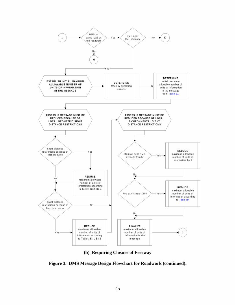
45
KDMS nearthe roadwork
Yes No1DMS on
same road asthe roadwork
M
No
ESTABLISH INITIAL MAXIMUMALLOWABLE NUMBER OFUNITS OF INFORMATION
IN THE MESSAGE
DETERMINEfreeway operating
speeds
DETERMINEini t ial maximum
allowable number ofunits of information
in the messagefrom Table B1
ASSESS IF MESSAGE MUST BEREDUCED BECAUSE OF
LOCAL GEOMETRIC SIGHTDISTANCE RESTRICTIONS
Sight distancerestrict ions because of
horizontal curve
NoREDUCE
maximum al lowablenumber of units of
information accordingto Tables B2.1-B2.4
Yes
REDUCEmaximum al lowablenumber of units of
information accordingto Tables B3.1-B3.6
ASSESS IF MESSAGE MUST BEREDUCED BECAUSE OF LOCAL
ENVIRONMENTAL SIGHTDISTANCE RESTRICTIONS
Rainfal l near DMSexceeds 2 in/hr
Fog exists near DMS
No
REDUCEmaximum al lowablenumber of units ofinformation by 1
Yes
REDUCEmaximum al lowablenumber of units of
information accordingto Table B4
Yes
No
Yes
Yes
FINALIZEmaximum al lowablenumber of units ofinformation in the
message
No
J
Sight distancerestrict ions because of
vertical curve
(b) Requiring Closure of Freeway
Figure 3. DMS Message Design Flowchart for Roadwork (continued).

46
DEFINEBASIC M ESSAGE
TO SATISFY M OTORISTINFORM ATION NEEDS
SELECTRoadw ork Descrip tor
from Table *
SELECTClosure Location
from Table *
SELECTLanes C losedfrom Table *
SELECTType 6 D ivers ion (Detour)
Route A c tionfrom Table *
J
REDUCE THE NUM BEROF M ESSAGE UNITS IF
NECESSARY
Num ber o f un its ofinform ation in B as ic
M essage is g reate r thanm axim um allowab le
OM ITRoadw ork Descrip tor
according to gu ide linesin Section *
CNo
Y es
Num ber o f un its ofinform ation in B as ic
M essage is g reate r thanm axim um allowab le
C
OM ITin form ation according to
gu ide lines in Tab le *
C
No
Y es
(b) Requiring Closure of Freeway
Figure 3. DMS Message Design Flowchart for Roadwork (continued).

47
ESTABLISH INITIAL MAXIMUMALLOWABLE NUMBER OFUNITS OF INFORMATION
IN THE MESSAGE
DETERMINEfreeway operating
speeds
DETERMINEini t ial maximum
allowable number ofunits of information
in the messagefrom Table B1
ASSESS IF MESSAGE MUST BEREDUCED BECAUSE OF
LOCAL GEOMETRIC SIGHTDISTANCE RESTRICTIONS
Sight distancerestrict ions because of
horizontal curve
NoREDUCE
maximum al lowablenumber of units of
information accordingto Tables B2.1-B2.4
Yes
REDUCEmaximum al lowablenumber of units of
information accordingto Tables B3.1-B3.6
ASSESS IF MESSAGE MUST BEREDUCED BECAUSE OF LOCAL
ENVIRONMENTAL SIGHTDISTANCE RESTRICTIONS
Rainfal l near DMSexceeds 2 in/hr
Fog exists near DMS
No
REDUCEmaximum al lowablenumber of units ofinformation by 1
Yes
REDUCEmaximum al lowablenumber of units of
information accordingto Table B4
Yes
No
Yes
FINALIZEmaximum al lowablenumber of units ofinformation in the
message
No
L
Sight distancerestrict ions because of
vertical curve
K
(b) Requiring Closure of Freeway
Figure 3. DMS Message Design Flowchart for Roadwork (continued).

48
DEFINEBASIC M ESSAGE
TO SATISFY M OTORISTINFORM ATION NEEDS
SELECTRoadw ork Descriptor
from Tab le *
SELECTClosure Location
from Tab le *
SELECTLanes C losedfrom Tab le *
SELECTNo D ivers ion Action
from Tab le *
D ivers ionaction w ill be
recom m ended
L
W ant "soft"divers ion
No
Y es
SELECTS oft D iversion A ction
from Tab le *
SELECTType 6 D ivers ion (Detour)
Route A ctionfrom Tab le *
A ction is fora selec t group of
m otorists
SELECTA udience for
A ctionfrom Tab le *
SELECTO ne G ood R eason
for Follow ingA ction
from Tab le *
D ivers ion route will beperceived as m ost
logical route
Y es
B
Y es
B
No
W ant Type 6divers ion
No
SELECTType 1 or 2 D ivers ion
Route A ctionfrom Tab le *
Y es
No
Y es
No
(b) Requiring Closure of Freeway
Figure 3. DMS Message Design Flowchart for Roadwork (continued).

49
ESTABLISH INITIAL MAXIMUMALLOWABLE NUMBER OFUNITS OF INFORMATION
IN THE MESSAGE
DETERMINEfreeway operating
speeds
DETERMINEini t ial maximum
allowable number ofunits of information
in the messagefrom Table B1
ASSESS IF MESSAGE MUST BEREDUCED BECAUSE OF
LOCAL GEOMETRIC SIGHTDISTANCE RESTRICTIONS
Sight distancerestrict ions because of
horizontal curve
No REDUCEmaximum al lowablenumber of units of
information accordingto Tables B2.1-B2.4
Yes
REDUCEmaximum al lowablenumber of units of
information accordingto Tables B3.1-B3.6
ASSESS IF MESSAGE MUST BEREDUCED BECAUSE OF LOCAL
ENVIRONMENTAL SIGHTDISTANCE RESTRICTIONS
Rainfal l near DMSexceeds 2 in/hr
Fog exists near DMS
No
REDUCEmaximum al lowablenumber of units ofinformation by 1
Yes
REDUCEmaximum al lowablenumber of units of
information accordingto Table B4
Yes
No
Yes
FINALIZEmaximum al lowablenumber of units ofinformation in the
message
No
N
Sight distancerestrict ions because of
vertical curve
M
(b) Requiring Closure of Freeway
Figure 3. DMS Message Design Flowchart for Roadwork (continued).

50
DEFINEBASIC MESSAGE
TO SATISFY MOTORISTINFORMATION NEEDS
SELECTRoadw ork Descriptor
from Table *
SELECTClosure Location
from Table *
SELECTLanes C losedfrom Table *
SELECTNo D ivers ion Action
from Table *
D ivers ionaction will be
recom m ended
N
W ant "soft"diversion
No
Yes
SELECTSoft D iversion Action
from Table *
Action is fora select group of
m otorists
SELECTAudience for
Actionfrom Table *
SELECTO ne Good Reason
for Follow ingAction
from Table *
D ivers ion route will beperce ived as m ost
logical route
Yes
B
Yes
B
No
SELECTType 1 or 2 D ivers ion
Route Actionfrom Table *
No
Yes
No
(b) Requiring Closure of Freeway
Figure 3. DMS Message Design Flowchart for Roadwork (continued).

51
4. ONGOING RESEARCH During the second year of this project, the TTI research team will focus on the following three tasks: • Task 4: Develop and Test a DMS Operations Manual for Use by DMS Operators in Texas; • Task 5: Determine Requirements of a Computerized Prototype to Assist Operators in DMS Message Design; and • Task 6: Develop Computer Prototype. In Task 4, researchers will convert the operations procedures, decision models, and flowcharts developed in Task 3 into a format that can be understood and used by all levels of operators (entry level, experienced operators, and operations managers). To accomplish this task, a manual for DMS operations will be developed. The manual will serve as the basis for explaining how and why the computer prototype to be developed in later tasks actually arrives at various decisions. In Task 5, researchers will develop the functional requirements of a computer prototype to help operators with DMS message design. In addition, researchers will identify the types of database requirements needed to effectively mimic the decision-making process of a human expert in DMS message design. It is anticipated that both of these tasks will be completed at the end of the second year of the project. In addition to these two tasks, the TTI research team will begin Task 6 (Develop Computer Prototype) during the second year and complete it by the end of the third year of the project.

53
5. REFERENCES 1. Durkop, B.R. The Use of Dynamic Message Signs for Diverting Traffic During Freeway
Incidents. In Compendium: Graduate Student Papers on Advanced Surface Transportation Systems, 1998. Southwest Region University Transportation Center, Texas Transportation Institute, Texas A&M University System, College Station, Texas, August 1998.
2. TxDOT Traffic Operations, Internal Agency Memorandum from Carol Rawson to Carlos
Lopez, August 30, 1996. 3. Dudek, C.L., N. Trout, S. Booth, and G.L. Ullman. Improved Dynamic Message Sign
Messages and Operations. Report FHWA/TX-01/1882-2. Texas Transportation Institute. October 2000.
4. Dudek, C.L. Guidelines on the Selection and Design of Messages for Changeable
Message Signs. Report FHWA/TX-92/1232-10. Texas Transportation Institute. November 1992.
5. Messer, C.J. and R.W. McNees. Evaluating Urban Freeway Guide Signing – Executive
Summary and Level of Service. Report FHWA/TX-82/31+220-4F. Texas Transportation Institute. August 1981.


55
APPENDIX A: TMC VISITS

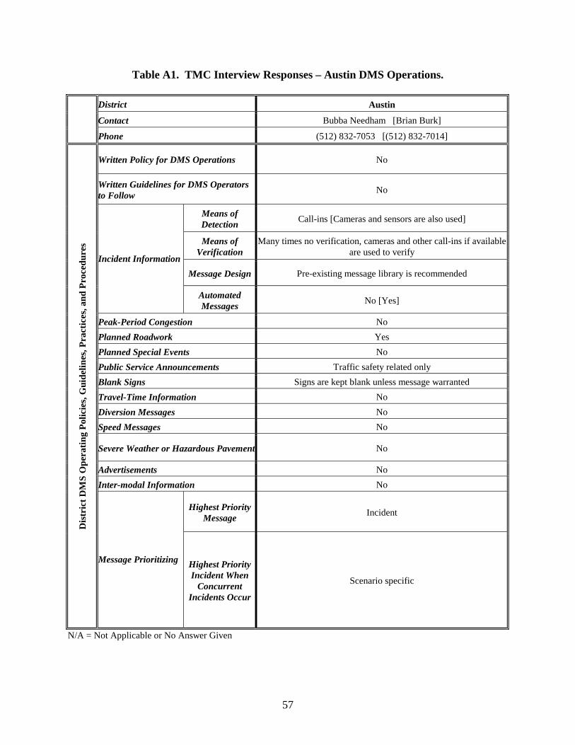
57
Table A1. TMC Interview Responses – Austin DMS Operations.
District Austin
Contact Bubba Needham [Brian Burk]
Phone (512) 832-7053 [(512) 832-7014]
Written Policy for DMS Operations No
Written Guidelines for DMS Operators to Follow
No
Means of Detection
Call-ins [Cameras and sensors are also used]
Means of Verification
Many times no verification, cameras and other call-ins if available are used to verify
Message Design Pre-existing message library is recommended
Incident Information
Automated Messages
No [Yes]
Peak-Period Congestion No
Planned Roadwork Yes
Planned Special Events No
Public Service Announcements Traffic safety related only
Blank Signs Signs are kept blank unless message warranted
Travel-Time Information No
Diversion Messages No
Speed Messages No
Severe Weather or Hazardous Pavement No
Advertisements No
Inter-modal Information No
Highest Priority Message
Incident
Dis
tric
t D
MS
Ope
rati
ng P
olic
ies,
Gui
delin
es, P
ract
ices
, and
Pro
cedu
res
Message Prioritizing Highest Priority Incident When
Concurrent Incidents Occur
Scenario specific
N/A = Not Applicable or No Answer Given
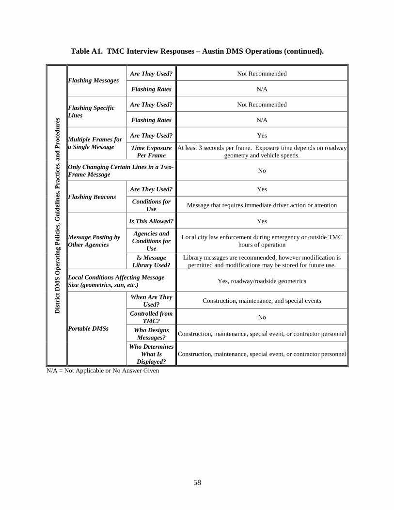
58
Table A1. TMC Interview Responses – Austin DMS Operations (continued).
Are They Used? Not Recommended Flashing Messages
Flashing Rates N/A
Are They Used? Not Recommended Flashing Specific Lines
Flashing Rates N/A
Are They Used? Yes Multiple Frames for a Single Message Time Exposure
Per Frame At least 3 seconds per frame. Exposure time depends on roadway
geometry and vehicle speeds.
Only Changing Certain Lines in a Two-Frame Message
No
Are They Used? Yes Flashing Beacons
Conditions for Use
Message that requires immediate driver action or attention
Is This Allowed? Yes
Agencies and Conditions for
Use
Local city law enforcement during emergency or outside TMC hours of operation
Message Posting by Other Agencies
Is Message Library Used?
Library messages are recommended, however modification is permitted and modifications may be stored for future use.
Local Conditions Affecting Message Size (geometrics, sun, etc.)
Yes, roadway/roadside geometrics
When Are They Used?
Construction, maintenance, and special events
Controlled from TMC?
No
Who Designs Messages?
Construction, maintenance, special event, or contractor personnel
Dis
tric
t D
MS
Ope
rati
ng P
olic
ies,
Gui
delin
es, P
ract
ices
, and
Pro
cedu
res
Portable DMSs
Who Determines What Is
Displayed? Construction, maintenance, special event, or contractor personnel
N/A = Not Applicable or No Answer Given
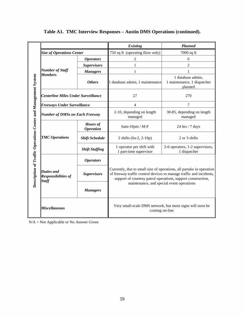
59
Table A1. TMC Interview Responses – Austin DMS Operations (continued).
N/A = Not Applicable or No Answer Given
Existing Planned
Size of Operations Center 750 sq ft (operating floor only) 7000 sq ft
Operators 2 6
Supervisors 1 2
Managers 1 1 Number of Staff Members
Others 1 database admin, 1 maintenance 1 database admin,
1 maintenance, 1 dispatcher planned
Centerline Miles Under Surveillance 27 270
Freeways Under Surveillance 4 7
Number of DMSs on Each Freeway 2-10, depending on length
managed 30-85, depending on length
managed
Hours of Operation
6am-10pm / M-F 24 hrs / 7 days
Shift Schedule 2 shifts (6a-2, 2-10p) 2 or 3 shifts TMC Operations
Shift Staffing 1 operator per shift with 1 part-time supervisor
2-6 operators, 1-2 supervisors, 1 dispatcher
Operators
Supervisors Duties and Responsibilities of Staff
Managers
Currently, due to small size of operations, all partake in operation of freeway traffic control devices to manage traffic and incidents,
support of courtesy patrol operations, support construction, maintenance, and special event operations
Des
crip
tion
of
Tra
ffic
Ope
rati
ons
Cen
ter
and
Man
agem
ent
Syst
em
Miscellaneous Very small-scale DMS network, but more signs will soon be
coming on-line

60
Table A2. TMC Interview Responses – Dallas DMS Operations.
District Dallas
Contact Terry Sams
Phone (214) 320-6231
Written Policy for DMS Operations No
Written Guidelines for DMS Operators to Follow
Yes
Means of Detection
Camera, Call-ins
Means of Verification
Cameras
Message Design Operator designs messages based on guidelines, however some
messages such as public information are stored in a library
Incident Information
Automated Messages
No
Peak-Period Congestion No
Planned Roadwork Yes
Planned Special Events Yes
Public Service Announcements Traffic safety related only
Blank Signs Signs are kept blank unless message warranted
Travel-Time Information No
Diversion Messages No, except for major construction closures
Speed Messages No
Severe Weather or Hazardous Pavement Yes
Advertisements No
Inter-modal Information No
Highest Priority Message
Incident
Dis
tric
t D
MS
Ope
rati
ng P
olic
ies,
Gui
delin
es, P
ract
ices
, and
Pro
cedu
res
Message Prioritizing Highest Priority Incident When
Concurrent Incidents Occur
Upstream incident
N/A = Not Applicable or No Answer Given

61
Table A2. TMC Interview Responses – Dallas DMS Operations (continued).
N/A = Not Applicable or No Answer Given
Are They Used? No Flashing Messages
Flashing Rates N/A
Are They Used? No Flashing Specific Lines
Flashing Rates N/A
Are They Used? Yes, max 2 frames per message Multiple Frames for a Single Message Time Exposure
Per Frame 2 seconds
Only Changing Certain Lines in a Two-Frame Message
Yes, top line with highway and directional info stays static - bottom line allowed to change
Are They Used? Yes Flashing Beacons
Conditions for Use
When lanes are blocked
Is This Allowed? No, however message requests are accepted and evaluated for
posting based on guidelines
Agencies and Conditions for
Use N/A
Message Posting by Other Agencies
Is Message Library Used?
N/A
Local Conditions Affecting Message Size (geometrics, sun, etc.)
No
When Are They Used?
Maintenance, construction, or traffic safety
Controlled from TMC?
No, messages are preprogrammed from the TMC prior to being used in the field
Who Designs Messages?
TMC designs the message based on the information provided by the requesting office
Dis
tric
t D
MS
Ope
rati
ng P
olic
ies,
Gui
delin
es, P
ract
ices
, and
Pro
cedu
res
Portable DMSs
Who Determines What Is
Displayed?
TMC designs the message based on the request in accordance with the district message guidelines

62
Table A2. TMC Interview Responses – Dallas DMS Operations (continued).
Size of Operations Center Currently 2100 sq ft (entire building);
new building is being designed
Operators 4
Supervisors 1
Managers N/A Number of Staff Members
Others N/A
Centerline Miles Under Surveillance 43
Freeways Under Surveillance 7
Number of DMSs on Each Freeway US75 - 4, I635 - 6, I30 - 6, I35 - 9, I20 - 1, I45 - 1, SH183 - 1,
Spur 366 - 1
Hours of Operation
5am-9:30pm / M-F
Shift Schedule 5am-1:30pm / 1pm-9:30pm TMC Operations
Shift Staffing 2 operators per shift, supervisor splits between shifts
Operators Monitoring incident information, creating an appropriate message,
ensuring the message is placed on the correct signs, and monitoring lane closure information
Supervisors Periodically review the messages being placed on the signs and
take corrective actions if necessary
Duties and Responsibilities of Staff
Managers N/A
Des
crip
tion
of
Tra
ffic
Ope
rati
ons
Cen
ter
and
Man
agem
ent
Syst
em
Miscellaneous Almost all signs are 1-mile upstream of fwy-to-fwy interchanges
N/A = Not Applicable or No Answer Given
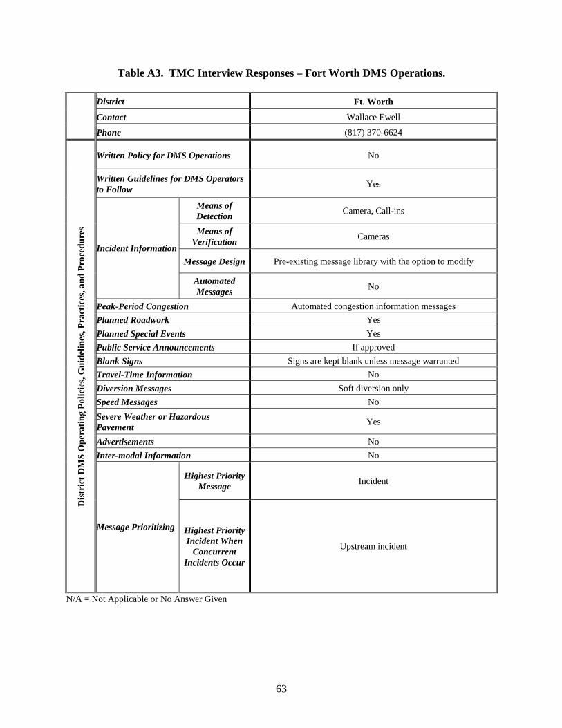
63
Table A3. TMC Interview Responses – Fort Worth DMS Operations.
District Ft. Worth
Contact Wallace Ewell
Phone (817) 370-6624
Written Policy for DMS Operations No
Written Guidelines for DMS Operators to Follow
Yes
Means of Detection
Camera, Call-ins
Means of Verification
Cameras
Message Design Pre-existing message library with the option to modify
Incident Information
Automated Messages
No
Peak-Period Congestion Automated congestion information messages
Planned Roadwork Yes
Planned Special Events Yes
Public Service Announcements If approved
Blank Signs Signs are kept blank unless message warranted
Travel-Time Information No
Diversion Messages Soft diversion only
Speed Messages No
Severe Weather or Hazardous Pavement
Yes
Advertisements No
Inter-modal Information No
Highest Priority Message
Incident
Dis
tric
t D
MS
Ope
rati
ng P
olic
ies,
Gui
delin
es, P
ract
ices
, and
Pro
cedu
res
Message Prioritizing Highest Priority Incident When
Concurrent Incidents Occur
Upstream incident
N/A = Not Applicable or No Answer Given
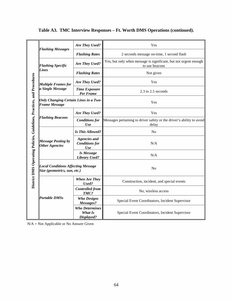
64
Table A3. TMC Interview Responses – Ft. Worth DMS Operations (continued).
N/A = Not Applicable or No Answer Given
Are They Used? Yes Flashing Messages
Flashing Rates 2 seconds message on-time, 1 second flash
Are They Used? Yes, but only when message is significant, but not urgent enough
to use beacons Flashing Specific Lines
Flashing Rates Not given
Are They Used? Yes Multiple Frames for a Single Message Time Exposure
Per Frame 2.3 to 2.5 seconds
Only Changing Certain Lines in a Two-Frame Message
Yes
Are They Used? Yes Flashing Beacons
Conditions for Use
Messages pertaining to driver safety or the driver’s ability to avoid delay
Is This Allowed? No
Agencies and Conditions for
Use N/A
Message Posting by Other Agencies
Is Message Library Used?
N/A
Local Conditions Affecting Message Size (geometrics, sun, etc.)
No
When Are They Used?
Construction, incident, and special events
Controlled from TMC?
No, wireless access
Who Designs Messages?
Special Event Coordinators, Incident Supervisor
Dis
tric
t D
MS
Ope
rati
ng P
olic
ies,
Gui
delin
es, P
ract
ices
, and
Pro
cedu
res
Portable DMSs
Who Determines What Is
Displayed? Special Event Coordinators, Incident Supervisor

65
Table A3. TMC Interview Responses – Ft. Worth DMS Operations (continued).
N/A = Not Applicable or No Answer Given
Size of Operations Center 32000 sq ft (entire center)
Operators 4
Supervisors 1
Managers 1 Number of Staff Members
Others 8 maintenance and 5 design
Centerline Miles Under Surveillance 50
Freeways Under Surveillance 7
Number of DMSs on Each Freeway Varies
Hours of Operation
6am-6pm / M-F
Shift Schedule 6am - 3pm and 9am - 6pm TMC Operations
Shift Staffing N/A
Operators
Supervisors Duties and Responsibilities of Staff
Managers
Monitor sensors and TVs for incidents, congestion, disabled vehicles, and unplanned construction; inform motorists via DMSs and lane control signals (LCSs); coordinate motorist assistance for disabled vehicles with courtesy patrol; coordinate information with
media and commercial traffic services.
Des
crip
tion
of
Tra
ffic
Ope
rati
ons
Cen
ter
and
Man
agem
ent
Syst
em
Miscellaneous Automation is used for congestion and
public information messages

66
Table A4. TMC Interview Responses – Houston DMS Operations.
District Houston
Contact Sally Wegmann
Phone 713-802-5171
Written Policy for DMS Operations No
Written Guidelines for DMS Operators to Follow
Yes
Means of Detection
Camera, Call-ins
Means of Verification
Cameras
Message Design Pre-existing message library, however situations may arise where
specially designed messages are needed
Incident Information
Automated Messages
No
Peak-Period Congestion Non-automated travel-time information messages
Planned Roadwork Yes
Planned Special Events Yes
Public Service Announcements Yes
Blank Signs Try to avoid blank signs for public-image purposes
Travel-Time Information Yes, Non-Automated
Diversion Messages Soft diversion for most incidents, hard diversion for major
closures
Speed Messages No
Severe Weather or Hazardous Pavement
Yes
Advertisements No
Inter-modal Information Yes, park-and-ride for special events
Highest Priority Message
Incident
Dis
tric
t D
MS
Ope
rati
ng P
olic
ies,
Gui
delin
es, P
ract
ices
, and
Pro
cedu
res
Message Prioritizing Highest Priority Incident When
Concurrent Incidents Occur
Scenario specific, but often upstream incident is highest priority
N/A = Not Applicable or No Answer Given

67
Table A4. TMC Interview Responses – Houston DMS Operations (continued).
N/A = Not Applicable or No Answer Given
Are They Used? No Flashing Messages
Flashing Rates N/A
Are They Used? No Flashing Specific Lines
Flashing Rates N/A
Are They Used? Yes Multiple Frames for a Single Message Time Exposure
Per Frame 2.5 seconds
Only Changing Certain Lines in a Two-Frame Message
Yes
Are They Used? Yes Flashing Beacons
Conditions for Use
Incidents and Construction
Is This Allowed? Yes
Agencies and Conditions for
Use
METRO has had permission to operate the TxDOT owned DMSs on the HOV lanes and in the park-and- ride lots for the last 4
years; however METRO does not utilize this privilege but rather makes requests to TxDOT who creates and posts the messages
Message Posting by Other Agencies
Is Message Library Used?
Yes
Local Conditions Affecting Message Size (geometrics, sun, etc.)
Yes
When Are They Used?
Construction, special events, and incidents (when no permanent DMS exist relative to the incident)
Controlled from TMC?
No, however programming of the portable DMS is performed by TxDOT TMC staff
Who Designs Messages?
TMC staff design messages for TxDOT-owned portable DMSs based on the requesting party, however if the portable DMSs are owned by a separate agency or contractor, the message approval responsibility lies with the TxDOT project manager or engineer
Dis
tric
t D
MS
Ope
rati
ng P
olic
ies,
Gui
delin
es, P
ract
ices
, and
Pro
cedu
res
Portable DMSs
Who Determines What Is
Displayed?
TMC staff or project staff depending on situation and sign ownership

68
Table A4. TMC Interview Responses – Houston DMS Operations (continued).
Size of Operations Center 56,100 sq ft (entire center)
Operators 12
Supervisors 3
Managers 1 Number of Staff Members
Others 1 engineering assistant
Centerline Miles Under Surveillance 179
Freeways Under Surveillance 7
Number of DMSs on Each Freeway I610 - 14, SH 288 - 2, SH 255 - 3, SH 146 - 2, I45 - 32, I10 - 14,
US 59 - 16, US 290 - 12, Beltway 8 - 3
Hours of Operation
24 hrs / 7 days
Shift Schedule 6am - 2pm / 2pm - 10pm / 10pm - 6am TMC Operations
Shift Staffing Shifts 1 and 2 - M-F = 4, S-S = 1; shift 3 - M-F = 2, S-S = 1
Operators Monitor traffic; disseminates traffic information; post messages
Supervisors
Supervises TMC floor operations; approves DMS messages; provides technical expertise to floor operators; disseminates
information to the public through various forms of communication; works under time critical conditions to resolve emergency traffic
incidents/situations
Duties and Responsibilities of Staff
Managers
Oversees development and revisions of new and existing ITS components; oversees and performs highly technical work for
advanced traffic management system (ATMS); supervises professional, technical and administrative employees;
communication with governmental officials and the general public
Des
crip
tion
of
Tra
ffic
Ope
rati
ons
Cen
ter
and
Man
agem
ent
Syst
em
Miscellaneous Largest DMS network in the state; very much against blank signs
for public-image purposes; will soon have expanded message automation capabilities
N/A = Not Applicable or No Answer Given

69
Table A5. TMC Interview Responses – San Antonio DMS Operations.
District San Antonio
Contact Pat Irwin
Phone 210-731-5249
Written Policy for DMS Operations No
Written Guidelines for DMS Operators to Follow
Yes
Means of Detection
Sensors, Cameras, Call-ins
Means of Verification
Cameras
Message Design Pre-existing message library, modify only with supervisor
approval
Incident Information
Automated Messages
Yes
Peak-Period Congestion Highly automated travel-time information messages
Planned Roadwork Yes
Planned Special Events Yes
Public Service Announcements Ozone Action Day messages only
Blank Signs Try to avoid blank signs during daytime
Travel-Time Information Yes, Automated
Diversion Messages Soft diversion only
Speed Messages No
Severe Weather or Hazardous Pavement
Yes
Advertisements No
Inter-modal Information No
Highest Priority Message
Incident
Dis
tric
t D
MS
Ope
rati
ng P
olic
ies,
Gui
delin
es, P
ract
ices
, and
Pro
cedu
res
Message Prioritizing Highest Priority Incident When
Concurrent Incidents Occur
Scenario specific
N/A = Not Applicable or No Answer Given
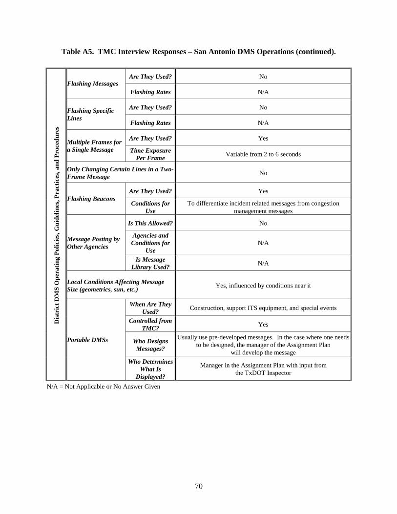
70
Table A5. TMC Interview Responses – San Antonio DMS Operations (continued).
N/A = Not Applicable or No Answer Given
Are They Used? No Flashing Messages
Flashing Rates N/A
Are They Used? No Flashing Specific Lines
Flashing Rates N/A
Are They Used? Yes Multiple Frames for a Single Message Time Exposure
Per Frame Variable from 2 to 6 seconds
Only Changing Certain Lines in a Two-Frame Message
No
Are They Used? Yes Flashing Beacons
Conditions for Use
To differentiate incident related messages from congestion management messages
Is This Allowed? No
Agencies and Conditions for
Use N/A
Message Posting by Other Agencies
Is Message Library Used?
N/A
Local Conditions Affecting Message Size (geometrics, sun, etc.)
Yes, influenced by conditions near it
When Are They Used?
Construction, support ITS equipment, and special events
Controlled from TMC?
Yes
Who Designs Messages?
Usually use pre-developed messages. In the case where one needs to be designed, the manager of the Assignment Plan
will develop the message
Dis
tric
t D
MS
Ope
rati
ng P
olic
ies,
Gui
delin
es, P
ract
ices
, and
Pro
cedu
res
Portable DMSs
Who Determines What Is
Displayed?
Manager in the Assignment Plan with input from the TxDOT Inspector

71
Table A5. TMC Interview Responses – San Antonio DMS Operations (continued).
Size of Operations Center 3441 sq ft (operating floor only)
Operators 6
Supervisors 2
Managers 3 Number of Staff Members
Others N/A
Centerline Miles Under Surveillance 73
Freeways Under Surveillance 7
Number of DMSs on Each Freeway I10 - 52, I35 - 44, I37 - 7, I410 - 42, US 90 - 19, US 281 - 3,
US 1604 - 7
Hours of Operation
4am-midnight / M-F, 5am-midnight / S-S
Shift Schedule Operators/supervisors = 6am - 3pm / 11am - 8pm;
managers = 4am - 2:30pm / 2pm - 12am TMC Operations
Shift Staffing 2 operators, 1 manager per shift M-F; 1 manager only S-S
Operators Assigned specific areas to monitor; respond to ALL incident
alarms assigned to them; update lane closure data
Supervisors N/A Duties and Responsibilities of Staff
Managers Responsible for any text/display to inform motorists Des
crip
tion
of
Tra
ffic
Ope
rati
ons
Cen
ter
and
Man
agem
ent
Syst
em
Miscellaneous Very sophisticated operation of sign messages; one of the most
highly automated systems in the nation
N/A = Not Applicable or No Answer Given


73
APPENDIX B: FLOWCHART TABLES


75
Table B1. Maximum Number of Units of Information in DMS Message (Base Maximum Message Length).
Condition Type of DMS Speed Range
Mid-Day Washout Backlight Nighttime 0-35 mph 5 units 5 units 4 units 4 units 36-55 mph 4 units 4 units 4 units 4 units
Light-Emitting Diode (LED) A
56-70 mph 4 units 4 units 3 units 3 units 0-35 mph 5 units 5 units 4 units 4 units 36-55 mph 4 units 4 units 3 units 3 units Fiber-optic 56-70 mph 3 units 3 units 2 units 3 units 0-35 mph 5 units 5 units 4 units 4 units 36-55 mph 4 units 4 units 3 units 3 units
Incandescent Bulb
56-70 mph 3 units 3 units 2 units 3 units 0-35 mph 5 units 4 units 2 units 3 units 36-55 mph 4 units 3 units 1 unit 2 units
Reflective Disk
56-70 mph 3 units 2 units 1 unit 1 unit A Valid only for the newer aluminum indium gallium phosphide (or equivalent) LEDs.

76
Table B2.1. Number of Units of Information that Must Be Subtracted from Number Given in Table 1 Due to Vertical Curve
PERMANENT LED DMS A
Mounting Height: 20 feet.
Vertical Curve Design Speed Overhead 20-Foot Offset 60-Foot Offset Condition
30 mph
35 mph
40 mph
30 mph
35 mph
40 mph
30 mph
35 mph
40 mph
Mid-Day 1 unit 0 unit 0 unit 2 units 0 unit 0 unit 5 units 3 units 1 unit Washout 1 unit 0 unit 0 unit 2 units 0 unit 0 unit 5 units 3 units 1 unit Backlight 0 unit 0 unit 0 unit 1 unit 0 unit 0 unit 4 units 3 units 1 unit Nighttime 0 unit 0 unit 0 unit 1 unit 0 unit 0 unit 4 units 3 units 1 unit
A Valid only for the newer aluminum indium gallium phosphide (or equivalent) LEDs.
Table B2.2. Number of Units of Information that Must Be Subtracted from Number Given in Table 1 Due to Vertical Curve
PERMANENT LED DMS A Mounting Height: 25 feet.
Vertical Curve Design Speed
Overhead 20-Foot Offset 60-Foot Offset Condition 30
mph 35
mph 40
mph 30
mph 35
mph 40
mph 30
mph 35
mph 40
mph Mid-Day 0 unit 0 unit 0 unit 2 units 1 unit 0 unit 5 units 4 units 1 unit Washout 0 unit 0 unit 0 unit 2 units 1 unit 0 unit 5 units 4 units 1 unit Backlight 0 unit 0 unit 0 unit 1 unit 0 unit 0 unit 4 units 3 units 1 unit Nighttime 0 unit 0 unit 0 unit 1 unit 0 unit 0 unit 4 units 3 units 1 unit
A Valid only for the newer aluminum indium gallium phosphide (or equivalent) LEDs.

77
Table B2.3. Number of Units of Information that Must Be Subtracted from Number Given in Table 1 Due to Vertical Curve
PORTABLE LED DMS A Mounting Height: 7 feet.
Vertical Curve Design Speed
20-Foot Offset 60-Foot Offset Condition 30
mph 35
mph 40
mph 30
mph 35
mph 40
mph Mid-Day 3 units 2 units 1 unit 5 units 5 units 3 units Washout 3 units 2 units 1 unit 5 units 5 units 3 units Backlight 2 units 1 unit 1 unit 4 units 4 units 2 units Nighttime 2 units 1 unit 1 unit 4 units 4 units 2 units
A Valid only for the newer aluminum indium gallium phosphide (or equivalent) LEDs.
Table B2.4. Number of Units of Information that Must Be Subtracted from Number Given in Table 1 Due to Vertical Curve
PORTABLE LED DMS A Mounting Height: 10 feet.
Vertical Curve Design Speed
20-Foot Offset 60-Foot Offset Condition 30
mph 35
mph 40
mph 30
mph 35
mph 40
mph Mid-Day 2 units 2 units 1 unit 5 units 4 units 3 units Washout 2 units 2 units 1 unit 5 units 4 units 3 units Backlight 1 unit 1 unit 0 unit 4 units 3 units 2 units Nighttime 1 unit 1 unit 0 unit 4 units 3 units 2 units
A Valid only for the newer aluminum indium gallium phosphide (or equivalent) LEDs.

78
Table B3.1. Number of Units of Information that Must Be Subtracted from Number Given in Table 1 Due to Horizontal Curve
PORTABLE LED DMS A Offset: 2 feet
Traffic Operating Speeds: 0-35 MPH.
Mid-Day and Washout Backlight and Nighttime Offset of Sight Obstruction from Edge of
Travel Lanes (ft) Offset of Sight Obstruction from Edge of
Travel Lanes (ft)
Curve Radii
(ft) 10 20 50 100 150 200 250 10 20 50 100 150 200 250
250 500 750 1000
1250 1500 1750 2000
2250 2500 2750 3000
4000 5000 7500 10000
4 units 4 units 4 units 3 units
3 units 3 units 3 units 3 units
2 units 2 units 2 units 2 units
1 unit 1 unit 1 unit 1 unit
4 units 3 units 2 units 2 units
2 units 1 unit 1 unit 1 unit
1 unit 1 unit 1 unit 1 unit
1 unit
2 units 1 unit 1 unit 1 unit
1 unit 1 unit
1 unit 1 unit 1 unit
1 unit 1 unit 3 units 3 units 3 units 2 units
2 units 2 units 2 units 2 units
1 unit 1 unit 1 unit 1 unit
3 units 2 units 2 units 1 unit
1 unit 1 unit 1 unit 1 unit
1 unit
A Valid only for the newer aluminum indium gallium phosphide (or equivalent) LEDs.
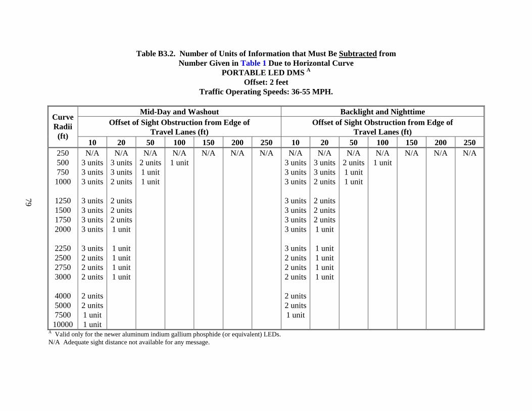
79
Table B3.2. Number of Units of Information that Must Be Subtracted from Number Given in Table 1 Due to Horizontal Curve
PORTABLE LED DMS A Offset: 2 feet
Traffic Operating Speeds: 36-55 MPH.
Mid-Day and Washout Backlight and Nighttime Offset of Sight Obstruction from Edge of
Travel Lanes (ft) Offset of Sight Obstruction from Edge of
Travel Lanes (ft)
Curve Radii
(ft) 10 20 50 100 150 200 250 10 20 50 100 150 200 250
250 500 750 1000
1250 1500 1750 2000
2250 2500 2750 3000
4000 5000 7500 10000
N/A 3 units 3 units 3 units
3 units 3 units 3 units 3 units
3 units 2 units 2 units 2 units
2 units 2 units 1 unit 1 unit
N/A 3 units 3 units 2 units
2 units 2 units 2 units 1 unit
1 unit 1 unit 1 unit 1 unit
N/A 2 units 1 unit 1 unit
N/A 1 unit
N/A N/A N/A N/A 3 units 3 units 3 units
3 units 3 units 3 units 3 units
3 units 2 units 2 units 2 units
2 units 2 units 1 unit
N/A 3 units 3 units 2 units
2 units 2 units 2 units 1 unit
1 unit 1 unit 1 unit 1 unit
N/A 2 units 1 unit 1 unit
N/A 1 unit
N/A N/A N/A
A Valid only for the newer aluminum indium gallium phosphide (or equivalent) LEDs. N/A Adequate sight distance not available for any message.

80
Table B3.3. Number of Units of Information that Must Be Subtracted from Number Given in Table 1 Due to Horizontal Curve
PORTABLE LED DMS A Offset: 2 feet
Traffic Operating Speeds: 56-70 MPH.
Mid-Day and Washout Backlight and Nighttime Offset of Sight Obstruction from Edge of
Travel Lanes (ft) Offset of Sight Obstruction from Edge of
Travel Lanes (ft)
Curve Radii
(ft) 10 20 50 100 150 200 250 10 20 50 100 150 200 250
250 500 750 1000
1250 1500 1750 2000
2250 2500 2750 3000
4000 5000 7500 10000
N/A N/A
3 units 3 units
3 units 3 units 3 units 3 units
3 units 3 units 3 units 3 units
2 units 2 units 2 units 2 units
N/A N/A
3 units 3 units
3 units 2 units 2 units 2 units
2 units 2 units 2 units 2 units
1 unit
N/A N/A
2 units 2 units
1 unit 1 unit 1 unit
N/A N/A
1 unit
N/A N/A
N/A
N/A
N/A N/A
2 units 1 unit
1 unit 1 unit 1 unit 1 unit
1 unit 1 unit 1 unit 1 unit
N/A N/A
1 unit 1 unit
1 unit
N/A N/A
N/A N/A
N/A N/A
N/A N/A
N/A N/A
A Valid only for the newer aluminum indium gallium phosphide (or equivalent) LEDs. N/A Adequate sight distance not available for any message.
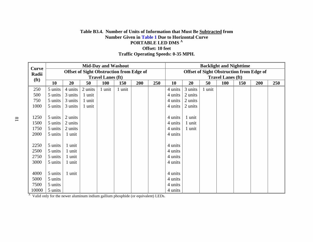
81
Table B3.4. Number of Units of Information that Must Be Subtracted from Number Given in Table 1 Due to Horizontal Curve
PORTABLE LED DMS A Offset: 10 feet
Traffic Operating Speeds: 0-35 MPH.
Mid-Day and Washout Backlight and Nighttime Offset of Sight Obstruction from Edge of
Travel Lanes (ft) Offset of Sight Obstruction from Edge of
Travel Lanes (ft)
Curve Radii
(ft) 10 20 50 100 150 200 250 10 20 50 100 150 200 250
250 500 750 1000
1250 1500 1750 2000
2250 2500 2750 3000
4000 5000 7500 10000
5 units 5 units 5 units 5 units
5 units 5 units 5 units 5 units
5 units 5 units 5 units 5 units
5 units 5 units 5 units 5 units
4 units 3 units 3 units 3 units
2 units 2 units 2 units 1 unit
1 unit 1 unit 1 unit 1 unit
1 unit
2 units 1 unit 1 unit 1 unit
1 unit 1 unit 4 units 4 units 4 units 4 units
4 units 4 units 4 units 4 units
4 units 4 units 4 units 4 units
4 units 4 units 4 units 4 units
3 units 2 units 2 units 2 units
1 unit 1 unit 1 unit
1 unit
A Valid only for the newer aluminum indium gallium phosphide (or equivalent) LEDs.

82
Table B3.5. Number of Units of Information that Must Be Subtracted from Number Given in Table 1 Due to Horizontal Curve
PORTABLE LED DMS A Offset: 10 feet
Traffic Operating Speeds: 36-55 MPH.
Mid-Day and Washout Backlight and Nighttime Offset of Sight Obstruction from Edge of
Travel Lanes (ft) Offset of Sight Obstruction from Edge of
Travel Lanes (ft)
Curve Radii
(ft) 10 20 50 100 150 200 250 10 20 50 100 150 200 250
250 500 750 1000
1250 1500 1750 2000
2250 2500 2750 3000
4000 5000 7500 10000
N/A 5 units 5 units 5 units
5 units 5 units 5 units 5 units
5 units 5 units 5 units 5 units
5 units 5 units 5 units 5 units
N/A 4 units 4 units 4 units
3 units 3 units 3 units 3 units
3 units 3 units 2 units 2 units
2 units 1 unit 1 unit 1 unit
N/A 3 units 2 units 2 units
1 unit 1 unit 1 unit 1 unit
1 unit 1 unit
N/A 2 units 1 unit 1 unit
N/A 1 unit 1 unit
N/A 1 unit
N/A N/A 5 units 5 units 5 units
5 units 5 units 5 units 5 units
5 units 5 units 5 units 5 units
5 units 5 units 5 units 5 units
N/A 3 units 3 units 3 units
2 units 2 units 2 units 2 units
2 units 2 units 1 unit 1 unit
N/A 2 units
N/A 1 unit
N/A N/A N/A
A Valid only for the newer aluminum indium gallium phosphide (or equivalent) LEDs. N/A Adequate sight distance not available for any message.

83
Table B3.6. Number of Units of Information that Must Be Subtracted from Number Given in Table 1 Due to Horizontal Curve
PORTABLE LED DMS A Offset: 10 feet
Traffic Operating Speeds: 56-70 MPH.
Mid-Day and Washout Backlight and Nighttime Offset of Sight Obstruction from Edge of
Travel Lanes (ft) Offset of Sight Obstruction from Edge of
Travel Lanes (ft)
Curve Radii
(ft) 10 20 50 100 150 200 250 10 20 50 100 150 200 250
250 500 750 1000
1250 1500 1750 2000
2250 2500 2750 3000
4000 5000 7500 10000
N/A N/A
5 units 5 units
5 units 5 units 5 units 5 units
5 units 5 units 5 units 5 units
5 units 5 units 5 units 5 units
N/A N/A
4 units 4 units
4 units 4 units 4 units 3 units
3 units 3 units 3 units 3 units
3 units 2 units 2 units 1 unit
N/A N/A
3 units 3 units
2 units 2 units 2 units 1 unit
1 unit 1 unit 1 unit 1 unit
1 unit
N/A N/A
2 units 1 unit
1 unit 1 unit 1 unit 1 unit
N/A N/A
1 unit 1 unit
1 unit
N/A 1 unit
N/A
N/A N/A
4 units 4 units
4 units 4 units 4 units 4 units
4 units 4 units 4 units 4 units
4 units 4 units 4 units 4 units
N/A N/A
3 units 3 units
3 units 3 units 3 units 2 units
2 units 2 units 2 units 2 units
2 units 1 unit 1 unit
N/A N/A
2 units 2 units
1 unit 1 unit 1 unit
N/A N/A
1 unit
N/A N/A
N/A N/A
N/A N/A
A Valid only for the newer aluminum indium gallium phosphide (or equivalent) LEDs. N/A Adequate sight distance not available for any message.

84
Table B4. Number of Units of Information that Must Be Subtracted from Number Given in Table 1 Due to Effects of Fog in Daytime Conditions
PORTABLE LED DMS. A
Overhead 20-Ft Offset 60-Ft Offset Visibility Range in
Fog 0-35 mph
36-55 mph
56-70 mph
0-35 mph
36-55 mph
56-70 mph
0-35 mph
36-55 mph
56-70 mph
1/2 mile 1/4 mile 1/10 mile
0 unit 0 unit 2 units
0 unit 0 unit 2 units
0 unit 1 unit 2 units
0 unit 0 unit 3 units
0 unit 1 unit 3 units
0 unit 1 unit 3 units
0 unit 2 units N/A
0 unit 2 units N/A
0 unit 2 units N/A
A Valid only for the newer aluminum indium gallium phosphide (or equivalent) LEDs. N/A Adequate sight distance not available for any message.