dmr introdu ction - tait radio academy · 3.5.1 site architecture ... contains technical requi...
TRANSCRIPT
TaitNDMRTraini
DMR-INT: V
Net DR Intring Ma
V1.00.04
DMRroduanual
ction
n

[This page is intentionally blank]
Page 1
CONTENTS
CHAPTER 1STANDARD . . . . . . . . . . . . . . . . . . . . . . . . . . . . . . . . . . . . . . . . . . . . . . . . . . . . . . . . 5
1.1 Learning Outcomes . . . . . . . . . . . . . . . . . . . . . . . . . . . . . . . . . . . . . . . . . .51.2 The Development of DMR . . . . . . . . . . . . . . . . . . . . . . . . . . . . . . . . . . . . .61.3 What Is DMR? . . . . . . . . . . . . . . . . . . . . . . . . . . . . . . . . . . . . . . . . . . . . . .61.4 DMR ETSI Standards . . . . . . . . . . . . . . . . . . . . . . . . . . . . . . . . . . . . . . . . .71.5 Benefits of DMR (Tier III) . . . . . . . . . . . . . . . . . . . . . . . . . . . . . . . . . . . . . .7
1.5.1 Open Standard . . . . . . . . . . . . . . . . . . . . . . . . . . . . . . . . . . . . . .81.5.2 Increased Capacity . . . . . . . . . . . . . . . . . . . . . . . . . . . . . . . . . . .81.5.3 Backwards spectrum compatibility . . . . . . . . . . . . . . . . . . . . . . .91.5.4 Digital Audio Quality . . . . . . . . . . . . . . . . . . . . . . . . . . . . . . . . . .91.5.5 Digital Services . . . . . . . . . . . . . . . . . . . . . . . . . . . . . . . . . . . . .121.5.6 Longer battery life and greater power efficiency . . . . . . . . . . . .121.5.7 Advanced control features . . . . . . . . . . . . . . . . . . . . . . . . . . . . .12
1.6 Benefits of Trunked Radio . . . . . . . . . . . . . . . . . . . . . . . . . . . . . . . . . . . .13
CHAPTER 2INTRODUCTION TO TRUNKING . . . . . . . . . . . . . . . . . . . . . . . . . . . . . . . . . . . . . . 15
2.1 Learning Outcomes . . . . . . . . . . . . . . . . . . . . . . . . . . . . . . . . . . . . . . . . .152.2 What is Trunking? . . . . . . . . . . . . . . . . . . . . . . . . . . . . . . . . . . . . . . . . . .162.3 Trunking Efficiency . . . . . . . . . . . . . . . . . . . . . . . . . . . . . . . . . . . . . . . . . .16
2.3.1 Trunking Developed of to Improve Quality of Service . . . . . . . .162.3.2 Trunking Developed to Improve Channel Utilization . . . . . . . . .172.3.3 Origin of Trunking . . . . . . . . . . . . . . . . . . . . . . . . . . . . . . . . . . .18
2.4 Trunked Radio Systems . . . . . . . . . . . . . . . . . . . . . . . . . . . . . . . . . . . . . .192.4.1 Trunked Radio Example . . . . . . . . . . . . . . . . . . . . . . . . . . . . . .20
2.5 Advantages of a Trunked Radio System . . . . . . . . . . . . . . . . . . . . . . . . .232.6 Optimizing Efficiency . . . . . . . . . . . . . . . . . . . . . . . . . . . . . . . . . . . . . . . .23
2.6.1 Organization . . . . . . . . . . . . . . . . . . . . . . . . . . . . . . . . . . . . . . .232.6.2 Queuing . . . . . . . . . . . . . . . . . . . . . . . . . . . . . . . . . . . . . . . . . . .242.6.3 Call Timing . . . . . . . . . . . . . . . . . . . . . . . . . . . . . . . . . . . . . . . .24
CHAPTER 3NETWORK ARCHITECTURE . . . . . . . . . . . . . . . . . . . . . . . . . . . . . . . . . . . . . . . . . 25
3.1 Learning Outcomes . . . . . . . . . . . . . . . . . . . . . . . . . . . . . . . . . . . . . . . . .253.2 DMR Network Overview . . . . . . . . . . . . . . . . . . . . . . . . . . . . . . . . . . . . . .263.3 DMR Network Elements . . . . . . . . . . . . . . . . . . . . . . . . . . . . . . . . . . . . . .273.4 Linking Infrastructure (IP Backbone) . . . . . . . . . . . . . . . . . . . . . . . . . . . .283.5 DMR Site Equipment . . . . . . . . . . . . . . . . . . . . . . . . . . . . . . . . . . . . . . . .29
3.5.1 Site Architecture . . . . . . . . . . . . . . . . . . . . . . . . . . . . . . . . . . . .293.5.2 TB9300 Base Station . . . . . . . . . . . . . . . . . . . . . . . . . . . . . . . .303.5.3 TB9300 Stand Alone Node . . . . . . . . . . . . . . . . . . . . . . . . . . . .313.5.4 Embedded Node Priority . . . . . . . . . . . . . . . . . . . . . . . . . . . . . .32
3.6 DMR Node Architecture . . . . . . . . . . . . . . . . . . . . . . . . . . . . . . . . . . . . . .333.6.1 Block Diagram of a DMR basic network architecture . . . . . . . .33
Issue 1.00.04© Tait Limited 2015
Page 2
3.6.2 Capacity . . . . . . . . . . . . . . . . . . . . . . . . . . . . . . . . . . . . . . . . . .343.6.3 DMR Node Operation . . . . . . . . . . . . . . . . . . . . . . . . . . . . . . . .343.6.4 Node Equipment . . . . . . . . . . . . . . . . . . . . . . . . . . . . . . . . . . . .34
3.7 DMR Network Gateways . . . . . . . . . . . . . . . . . . . . . . . . . . . . . . . . . . . . .363.7.1 TN8271 . . . . . . . . . . . . . . . . . . . . . . . . . . . . . . . . . . . . . . . . . . .363.7.2 Applications . . . . . . . . . . . . . . . . . . . . . . . . . . . . . . . . . . . . . . . .363.7.3 T1542 Line Dispatch Terminal . . . . . . . . . . . . . . . . . . . . . . . . .373.7.4 Conventional Gateway . . . . . . . . . . . . . . . . . . . . . . . . . . . . . . .383.7.5 MPT Gateway . . . . . . . . . . . . . . . . . . . . . . . . . . . . . . . . . . . . . .393.7.6 Telephone Gateways . . . . . . . . . . . . . . . . . . . . . . . . . . . . . . . .40
3.8 DMR Network Management Elements . . . . . . . . . . . . . . . . . . . . . . . . . . .423.8.1 Node Web UI . . . . . . . . . . . . . . . . . . . . . . . . . . . . . . . . . . . . . . .423.8.2 Tasks that can be carried out using the Node Web UI: . . . . . . .423.8.3 Tait EnableFleet . . . . . . . . . . . . . . . . . . . . . . . . . . . . . . . . . . . .443.8.4 Tait EnableMonitor . . . . . . . . . . . . . . . . . . . . . . . . . . . . . . . . . .453.8.5 Tait EnableReport . . . . . . . . . . . . . . . . . . . . . . . . . . . . . . . . . . .46
3.9 DMR Mobile and Portable Subscriber Units . . . . . . . . . . . . . . . . . . . . . . .473.10 DMR Voice Recorder . . . . . . . . . . . . . . . . . . . . . . . . . . . . . . . . . . . . . . . .483.11 Eventide NexLog Voice Recorder . . . . . . . . . . . . . . . . . . . . . . . . . . . . . .48
3.11.1 Overview . . . . . . . . . . . . . . . . . . . . . . . . . . . . . . . . . . . . . . . . . .483.11.2 MediaWorks PLUS . . . . . . . . . . . . . . . . . . . . . . . . . . . . . . . . . .49
CHAPTER 4CHANNEL OPERATION AND CONFIGURATION . . . . . . . . . . . . . . . . . . . . . . . . . 51
4.1 Learning Outcomes . . . . . . . . . . . . . . . . . . . . . . . . . . . . . . . . . . . . . . . . .514.2 Logical Channels . . . . . . . . . . . . . . . . . . . . . . . . . . . . . . . . . . . . . . . . . . .52
4.2.1 Logical Channel Categories . . . . . . . . . . . . . . . . . . . . . . . . . . .524.3 DMR Channel Operation and Configuration . . . . . . . . . . . . . . . . . . . . . .53
4.3.1 Control Channel . . . . . . . . . . . . . . . . . . . . . . . . . . . . . . . . . . . .534.3.2 Control Channel Facilities . . . . . . . . . . . . . . . . . . . . . . . . . . . . .534.3.3 Control Channel Configurations . . . . . . . . . . . . . . . . . . . . . . . .534.3.4 Traffic Channel . . . . . . . . . . . . . . . . . . . . . . . . . . . . . . . . . . . . .544.3.5 Traffic Channel Configurations . . . . . . . . . . . . . . . . . . . . . . . . .54
4.4 Channel Numbering . . . . . . . . . . . . . . . . . . . . . . . . . . . . . . . . . . . . . . . . .554.4.1 Channel Numbering Calculations . . . . . . . . . . . . . . . . . . . . . . .56
CHAPTER 5CALL TYPES. . . . . . . . . . . . . . . . . . . . . . . . . . . . . . . . . . . . . . . . . . . . . . . . . . . . . . 57
5.1 Learning Outcomes . . . . . . . . . . . . . . . . . . . . . . . . . . . . . . . . . . . . . . . . .575.2 DMR Call Type Overview . . . . . . . . . . . . . . . . . . . . . . . . . . . . . . . . . . . . .585.3 Voice Calls - Talkgroup . . . . . . . . . . . . . . . . . . . . . . . . . . . . . . . . . . . . . .58
5.3.1 Talkgroup - Conference Call . . . . . . . . . . . . . . . . . . . . . . . . . . .595.3.2 Talkgroup - Broadcast Call . . . . . . . . . . . . . . . . . . . . . . . . . . . .60
5.4 Voice Calls - Individual . . . . . . . . . . . . . . . . . . . . . . . . . . . . . . . . . . . . . . .615.5 Data Calls . . . . . . . . . . . . . . . . . . . . . . . . . . . . . . . . . . . . . . . . . . . . . . . . .62
5.5.1 Control Channel Data - Status Message . . . . . . . . . . . . . . . . . .625.5.2 Control Channel Data - SDM . . . . . . . . . . . . . . . . . . . . . . . . . . .645.5.3 Traffic Channel Data - Packet Data Call . . . . . . . . . . . . . . . . . .655.5.4 Control and/or Traffic Channel Data . . . . . . . . . . . . . . . . . . . . .66
5.6 Gateway Calls . . . . . . . . . . . . . . . . . . . . . . . . . . . . . . . . . . . . . . . . . . . . .685.7 Self Test Call . . . . . . . . . . . . . . . . . . . . . . . . . . . . . . . . . . . . . . . . . . . . . .69
Issue 1.00.04© Tait Limited 2015
Page 3
CHAPTER 6CALL FEATURES . . . . . . . . . . . . . . . . . . . . . . . . . . . . . . . . . . . . . . . . . . . . . . . . . . 71
6.1 Learning Outcomes . . . . . . . . . . . . . . . . . . . . . . . . . . . . . . . . . . . . . . . . .716.2 DMR Call Handling Strategies . . . . . . . . . . . . . . . . . . . . . . . . . . . . . . . . .72
6.2.1 Transmission Trunked . . . . . . . . . . . . . . . . . . . . . . . . . . . . . . . .726.2.2 Message Trunked . . . . . . . . . . . . . . . . . . . . . . . . . . . . . . . . . . .726.2.3 Individual Call Setup Handling Strategy . . . . . . . . . . . . . . . . . .736.2.4 Group Call Setup Handling Strategy . . . . . . . . . . . . . . . . . . . . .736.2.5 Queuing Strategy . . . . . . . . . . . . . . . . . . . . . . . . . . . . . . . . . . .74
6.3 DMR Call Timers . . . . . . . . . . . . . . . . . . . . . . . . . . . . . . . . . . . . . . . . . . .756.3.1 Call Time Limits . . . . . . . . . . . . . . . . . . . . . . . . . . . . . . . . . . . . .756.3.2 Other Timers . . . . . . . . . . . . . . . . . . . . . . . . . . . . . . . . . . . . . . .75
6.4 DMR Emergency and Priority Calls . . . . . . . . . . . . . . . . . . . . . . . . . . . . .776.4.1 Emergency Calls . . . . . . . . . . . . . . . . . . . . . . . . . . . . . . . . . . . .776.4.2 Priority Group Override . . . . . . . . . . . . . . . . . . . . . . . . . . . . . . .786.4.3 Priority Calls . . . . . . . . . . . . . . . . . . . . . . . . . . . . . . . . . . . . . . .806.4.4 Minimum Access Level . . . . . . . . . . . . . . . . . . . . . . . . . . . . . . .816.4.5 Configuration . . . . . . . . . . . . . . . . . . . . . . . . . . . . . . . . . . . . . . .826.4.6 Operational Considerations . . . . . . . . . . . . . . . . . . . . . . . . . . . .82
6.5 DMR Network Optimization Strategies . . . . . . . . . . . . . . . . . . . . . . . . . . .836.5.1 User Profiles . . . . . . . . . . . . . . . . . . . . . . . . . . . . . . . . . . . . . . .836.5.2 Individual Service Areas . . . . . . . . . . . . . . . . . . . . . . . . . . . . . .836.5.3 Group Calls - Fixed Service Area . . . . . . . . . . . . . . . . . . . . . . .836.5.4 Groups Call - Controlled Service Area . . . . . . . . . . . . . . . . . . .886.5.5 Mobility . . . . . . . . . . . . . . . . . . . . . . . . . . . . . . . . . . . . . . . . . . .906.5.6 Asset Management . . . . . . . . . . . . . . . . . . . . . . . . . . . . . . . . . .906.5.7 Stun and Revive . . . . . . . . . . . . . . . . . . . . . . . . . . . . . . . . . . . .916.5.8 Authentication key . . . . . . . . . . . . . . . . . . . . . . . . . . . . . . . . . . .91
6.6 Subscriber Unit Call Features . . . . . . . . . . . . . . . . . . . . . . . . . . . . . . . . .926.7 Detailed Queuing Reference . . . . . . . . . . . . . . . . . . . . . . . . . . . . . . . . . .93
6.7.1 Queuing Overview . . . . . . . . . . . . . . . . . . . . . . . . . . . . . . . . . . .936.7.2 Qued Call Scenarios . . . . . . . . . . . . . . . . . . . . . . . . . . . . . . . . .936.7.3 Channel Management for Queuing . . . . . . . . . . . . . . . . . . . . . .95
CHAPTER 7NUMBERING . . . . . . . . . . . . . . . . . . . . . . . . . . . . . . . . . . . . . . . . . . . . . . . . . . . . . . 97
7.1 Learning Outcomes . . . . . . . . . . . . . . . . . . . . . . . . . . . . . . . . . . . . . . . . .977.2 Numbering Compatibility . . . . . . . . . . . . . . . . . . . . . . . . . . . . . . . . . . . . .98
7.2.1 Numbering schemes available . . . . . . . . . . . . . . . . . . . . . . . . .987.3 DMR Numbering . . . . . . . . . . . . . . . . . . . . . . . . . . . . . . . . . . . . . . . . . . .987.4 MPT 1327 Addressing . . . . . . . . . . . . . . . . . . . . . . . . . . . . . . . . . . . . . . .997.5 Dialling Calls in MPT1327 . . . . . . . . . . . . . . . . . . . . . . . . . . . . . . . . . . .101
7.5.1 MPT1327 Dialling String Summary . . . . . . . . . . . . . . . . . . . . .101
Issue 1.00.04© Tait Limited 2015

Page 4
Issue 1.00.04© Tait Limited 2015
1.1 Learning Outcomes Page 5
Chapter 1Standard
1.1 Learning Outcomes
Upon completion of this chapter, you will be able to do the following:
• Explain the need for the development of DMR
• Define what DMR is
• Identify DMR ETSI standards
• Describe the benefits of DMR Tier III
• Explain the benefits of a trunked radio system
Issue 1.00.04© Tait Limited 2015
Page 6 Chapter 1: Standard
1.2 The Development of DMR
Background
It was recognized by vendors and users of radio systems that there is the need to supersede the existing analog trunking standards with modern techniques to provide:
1. Improved voice quality2. Improved functionality (i.e. Location information)3. Improved security (i.e. Authentication)4. Improved channel efficiency (2 slot TDMA)
1.3 What Is DMR?
Digital Mobile Radio (DMR) is an international digital radio standard developed by the European Telecommunications Standards Institute (ETSI), and first ratified in 2005. The standard now provides a full set of standards covering voice, data services and conformance tests.
DMR aims to provide a economical, low-complexity digital standard to replace analog radio. The ETSI DMR Standard, TS102 361, defines three different tiers.
• Tier I (unlicensed): DMR equipment having an integral antenna and working in Direct Mode (unit-to-unit) under a general authorization with no individual rights operation.
• Tier II (licensed conventional): DMR systems operating under individual licences working in Direct Mode (unit-to-unit) or using a Base Station (BS) for repeating.
• Tier III (licensed trunked): DMR trunking systems under individual licences operating with a controller function that automatically regulates the communications.
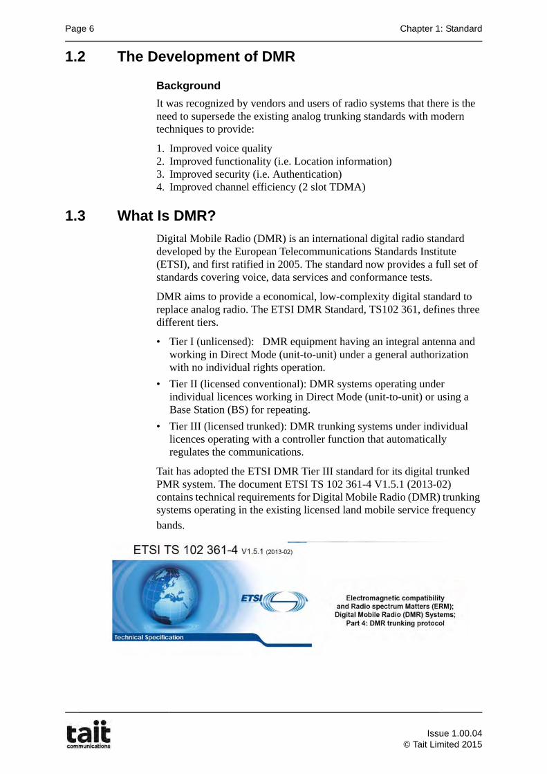
Tait has adopted the ETSI DMR Tier III standard for its digital trunked PMR system. The document ETSI TS 102 361-4 V1.5.1 (2013-02) contains technical requirements for Digital Mobile Radio (DMR) trunking systems operating in the existing licensed land mobile service frequency
bands.
Issue 1.00.04
© Tait Limited 2015
1.4 DMR ETSI Standards Page 7
1.4 DMR ETSI Standards
The full list of ETSI standards that define DMR primarily consist of four documents:
ETSI TS 102 361-1:
"Electromagnetic compatibility and Radio spectrum Matters (ERM); Digital Mobile Radio (DMR) Systems; Part 1: DMR Air Interface (AI) protocol".
ETSI TS 102 361-2:
"Electromagnetic compatibility and Radio spectrum Matters (ERM); Digital Mobile Radio (DMR) Systems; Part 2: DMR voice and generic services and facilities“.
ETSI TS 102 361-3:
"Electromagnetic compatibility and Radio spectrum Matters (ERM); Digital Mobile Radio (DMR) Systems; Part 3: DMR data protocol".
ETSI TS 102 361-4:
"Electromagnetic compatibility and Radio spectrum Matters (ERM); Digital Mobile Radio (DMR) Systems; Part 4: DMR trunking protocol".
1.5 Benefits of DMR (Tier III)
DMR has the following benefits:
• Open Standard (non-proprietary)
• Increased capacity (TDMA)
• Backwards spectrum compatibility with legacy analog systems
• Digital Audio Quality
• Digital services
• Longer battery life and greater power efficiency
• Advanced control features
• Advantages of a DMR trunked radio system
• Trunking efficiency
Issue 1.00.04© Tait Limited 2015
Page 8 Chapter 1: Standard
1.5.1 Open Standard
DMR is an ‘open’ standard and is not proprietary to a single manufacturer. This means that competition is possible between manufacturers not only when a new system is purchased, but over the life time of the system (e.g. each time new subscriber units are purchased).
1.5.2 Increased Capacity
Time Division Multiple Access (TDMA)
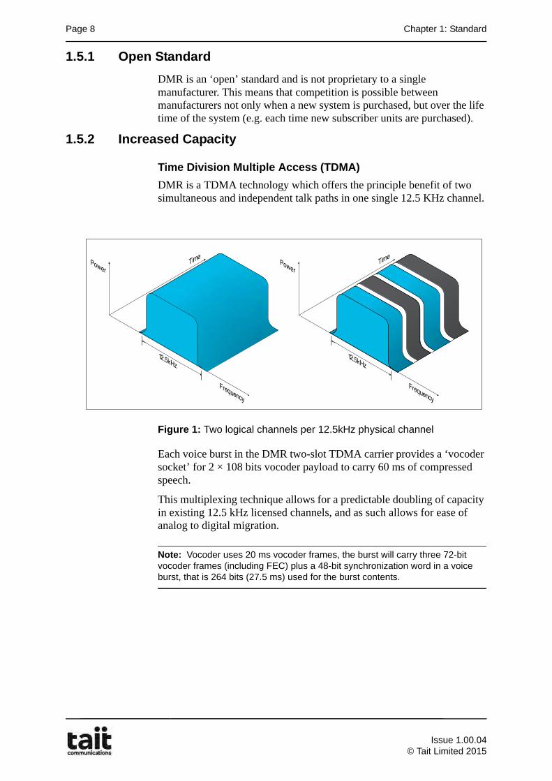
DMR is a TDMA technology which offers the principle benefit of two simultaneous and independent talk paths in one single 12.5 KHz channel.
Figure 1: Two logical channels per 12.5kHz physical channel
Each voice burst in the DMR two-slot TDMA carrier provides a ‘vocoder socket’ for 2 × 108 bits vocoder payload to carry 60 ms of compressed speech.
This multiplexing technique allows for a predictable doubling of capacity in existing 12.5 kHz licensed channels, and as such allows for ease of analog to digital migration.
Note: Vocoder uses 20 ms vocoder frames, the burst will carry three 72-bit vocoder frames (including FEC) plus a 48-bit synchronization word in a voice burst, that is 264 bits (27.5 ms) used for the burst contents.
Time
Power
Frequency
12.5kHz
Time
Power
Frequency
12.5kHz
Issue 1.00.04
© Tait Limited 2015
1.5 Benefits of DMR (Tier III) Page 9
1.5.3 Backwards spectrum compatibility
Analog to Digital Migration
As DMR is designed for ease of analog to digital migration, a major design goal was that the output spectrum must fit in to the existing 12.5 kHz narrowband FM channels used by legacy analog systems.
DMR Modulation
With this design criteria, the choice of modulation scheme and associated symbol rate were critical. The outcome was that 4FSK, 4-level Frequency Shift Keying, modulation was used with an associated symbol rate of 4800 symbols/sec (9600bits/sec, i.e. 2 bits per symbol).
4FSK
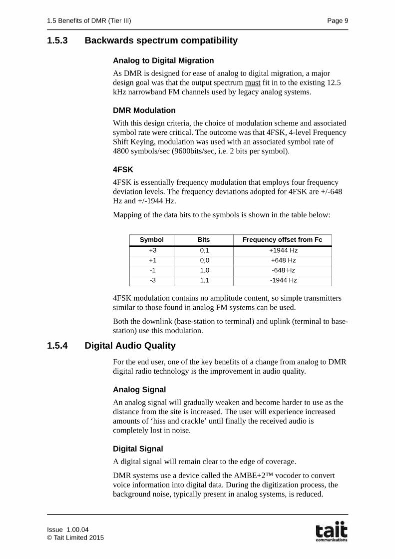
4FSK is essentially frequency modulation that employs four frequency deviation levels. The frequency deviations adopted for 4FSK are +/-648 Hz and +/-1944 Hz.
Mapping of the data bits to the symbols is shown in the table below:
4FSK modulation contains no amplitude content, so simple transmitters similar to those found in analog FM systems can be used.
Both the downlink (base-station to terminal) and uplink (terminal to base-station) use this modulation.
1.5.4 Digital Audio Quality
For the end user, one of the key benefits of a change from analog to DMR digital radio technology is the improvement in audio quality.
Analog Signal
An analog signal will gradually weaken and become harder to use as the distance from the site is increased. The user will experience increased amounts of ‘hiss and crackle’ until finally the received audio is completely lost in noise.
Digital Signal
A digital signal will remain clear to the edge of coverage.
DMR systems use a device called the AMBE+2™ vocoder to convert voice information into digital data. During the digitization process, the background noise, typically present in analog systems, is reduced.
Symbol Bits Frequency offset from Fc
+3 0,1 +1944 Hz
+1 0,0 +648 Hz
-1 1,0 -648 Hz
-3 1,1 -1944 Hz
Issue 1.00.04© Tait Limited 2015
Page 10 Chapter 1: Standard
The data is then protected using Forward Error Correction (FEC), and Cyclic Redundancy Check (CRC) coders before being transmitted over the air.
These coders enable receiving radios to detect and automatically correct transmission errors by analyzing bits inserted into messages that enable the receiving radio to tell if there is an error.
Through the use of coders and other techniques, digital processing is able to screen out noise and re-construct signals from degraded transmissions.
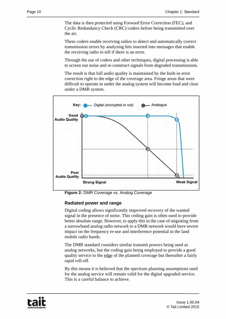
The result is that full audio quality is maintained by the built-in error correction right to the edge of the coverage area. Fringe areas that were difficult to operate in under the analog system will become loud and clear under a DMR system.
Figure 2: DMR Coverage vs. Analog Coverage
Radiated power and range
Digital coding allows significantly improved recovery of the wanted signal in the presence of noise. This coding gain is often used to provide better absolute range. However, to apply this in the case of migrating from a narrowband analog radio network to a DMR network would have severe impact on the frequency re-use and interference potential in the land mobile radio bands.
The DMR standard considers similar transmit powers being used as analog networks, but the coding gain being employed to provide a good quality service to the edge of the planned coverage but thereafter a fairly rapid roll-off.
By this means it is believed that the spectrum planning assumptions used for the analog service will remain valid for the digital upgraded service. This is a careful balance to achieve.
Good Audio Quality
Poor Audio Quality
30dB
20dB
12dB
7dB
Strong Signal Weak Signal
2.5 V-99dBm
0.45 V-114dBm
0.19 V-121dBm
0.14 V-124dBm
Key: AnalogDigital
Minimal Acceptable Audio Quality
Digital Advantage
Audio
Quality
Coverage
Issue 1.00.04
© Tait Limited 2015
1.5 Benefits of DMR (Tier III) Page 11
Vocoder
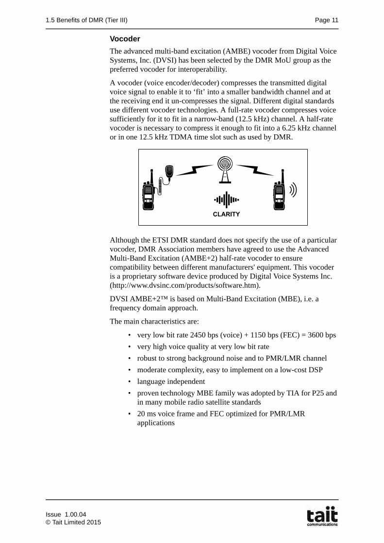
The advanced multi-band excitation (AMBE) vocoder from Digital Voice Systems, Inc. (DVSI) has been selected by the DMR MoU group as the preferred vocoder for interoperability.
A vocoder (voice encoder/decoder) compresses the transmitted digital voice signal to enable it to ‘fit’ into a smaller bandwidth channel and at the receiving end it un-compresses the signal. Different digital standards use different vocoder technologies. A full-rate vocoder compresses voice sufficiently for it to fit in a narrow-band (12.5 kHz) channel. A half-rate vocoder is necessary to compress it enough to fit into a 6.25 kHz channel or in one 12.5 kHz TDMA time slot such as used by DMR.
Although the ETSI DMR standard does not specify the use of a particular vocoder, DMR Association members have agreed to use the Advanced Multi-Band Excitation (AMBE+2) half-rate vocoder to ensure compatibility between different manufacturers' equipment. This vocoder is a proprietary software device produced by Digital Voice Systems Inc. (http://www.dvsinc.com/products/software.htm).
DVSI AMBE+2™ is based on Multi-Band Excitation (MBE), i.e. a frequency domain approach.
The main characteristics are:
• very low bit rate 2450 bps (voice) + 1150 bps (FEC) = 3600 bps
• very high voice quality at very low bit rate
• robust to strong background noise and to PMR/LMR channel
• moderate complexity, easy to implement on a low-cost DSP
• language independent
• proven technology MBE family was adopted by TIA for P25 and in many mobile radio satellite standards
• 20 ms voice frame and FEC optimized for PMR/LMR applications
Issue 1.00.04© Tait Limited 2015
Page 12 Chapter 1: Standard
1.5.5 Digital Services
Data Applications
The end-to-end digital nature of DMR enables applications such as text messaging, GPS, and telemetry to be easily added onto radio devices and systems. As the DMR standard also supports the transmission of IP data over the air, this enables the easy development of standard applications. In a world which increasingly relies on data as well as voice communication, this ability to add a wide range of data applications to your system results in the greatest possible return on your investment. In fact, one of the key drivers for users switching to digital is to add business enhancing data services and applications to radio systems.
1.5.6 Longer battery life and greater power efficiency
One of the biggest challenges with mobile/portable devices has always been battery life. In the past, there have been limited options for increasing the talk time on a single battery charge.
Two-slot TDMA, however, offers a good way forward. Since an individual call uses only one of the two time slots, it requires only half of the transmitter's capacity. The transmitter is idle half of the time.
For typical Portable radio operating with the standard portable 5/5/90 duty cycle (5% Transmit, 5% Receive at full audio, 90% Standby) this effectively means you are only really transmitting for 2.5% of the time (half of the 5% Tx allowance). Given that the highest current draws on the battery occurs when the radio is transmitting, we can see the effective 2.5% transmit time reduction results in a significant increase in the shift life of the battery (i.e.: the time between charges). This translates to a 40% increase in battery shift life.
1.5.7 Advanced control features
The DMR standard allows for the ability to use the second time slot for reverse-channel signaling that is, instructions in the form of signaling being sent to the radio on the second time slot channel while the first channel is in a call. This capability can be used for priority call control, remote control of the transmitting radio or emergency call pre-emption and gives precise control and flexibility to the operator of a radio system. FDMA systems cannot deliver similar functionality because they are limited to one path only per spectrum channel.
Issue 1.00.04
© Tait Limited 2015
1.6 Benefits of Trunked Radio Page 13
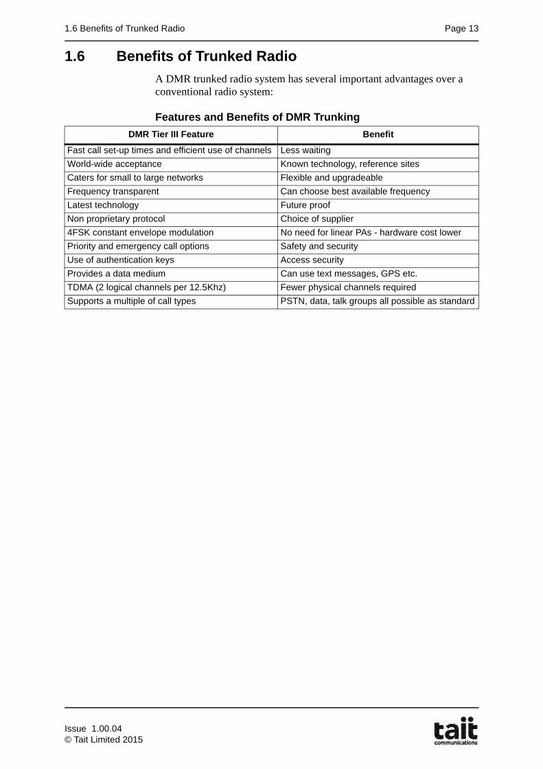
1.6 Benefits of Trunked Radio
A DMR trunked radio system has several important advantages over a conventional radio system:
Features and Benefits of DMR Trunking
DMR Tier III Feature Benefit
Fast call set-up times and efficient use of channels Less waiting
World-wide acceptance Known technology, reference sites
Caters for small to large networks Flexible and upgradeable
Frequency transparent Can choose best available frequency
Latest technology Future proof
Non proprietary protocol Choice of supplier
4FSK constant envelope modulation No need for linear PAs - hardware cost lower
Priority and emergency call options Safety and security
Use of authentication keys Access security
Provides a data medium Can use text messages, GPS etc.
TDMA (2 logical channels per 12.5Khz) Fewer physical channels required
Supports a multiple of call types PSTN, data, talk groups all possible as standard
Issue 1.00.04© Tait Limited 2015

Page 14 Chapter 1: Standard
Issue 1.00.04
© Tait Limited 2015
2.1 Learning Outcomes Page 15
Chapter 2Introduction to Trunking
2.1 Learning Outcomes
Upon completion of this chapter, you will be able to do the following:
• Define the term trunking as it applies to radio communications.
• Explain how trunking improves service and efficiency of a multi channel radio system.
• Explain the difference between Transmission trunking, Message trunking and quasi transmission trunking.
• Explain what is meant by the term Control Channel and describe its purpose.
• Explain what is meant by the term Traffic Channel and describe its purpose.
Issue 1.00.04© Tait Limited 2015
Page 16 Chapter 2: Introduction to Trunking
2.2 What is Trunking?
Trunking describes the process of selecting one clear communications path from many possibilities. Trunking is based on the premise that if 100 users are sharing a certain communications network, only around 10 users will actually use the network at any one time. Trunking is used in many forms of telecommunications.
This principle can be applied to radio systems where a small number of channels can be shared by many users. In trunked radio communications channel allocation is:
• Dynamic
• Automatic
An added benefit of trunked radio communications is the ability to free up (pre-empt) resources for a radio user in the event of an emergency.
2.3 Trunking Efficiency
2.3.1 Trunking Developed of to Improve Quality of Service
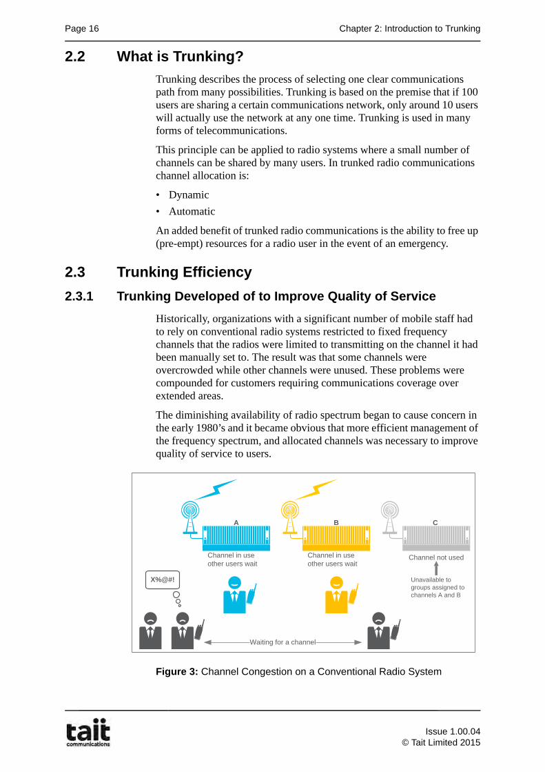
Historically, organizations with a significant number of mobile staff had to rely on conventional radio systems restricted to fixed frequency channels that the radios were limited to transmitting on the channel it had been manually set to. The result was that some channels were overcrowded while other channels were unused. These problems were compounded for customers requiring communications coverage over extended areas.
The diminishing availability of radio spectrum began to cause concern in the early 1980’s and it became obvious that more efficient management of the frequency spectrum, and allocated channels was necessary to improve quality of service to users.
Figure 3: Channel Congestion on a Conventional Radio System
Channel not usedChannel in use other users wait
Channel in use other users wait
Unavailable to groups assigned to channels A and B
Waiting for a channel
BA C
X%@#!
Issue 1.00.04
© Tait Limited 2015
2.3 Trunking Efficiency Page 17
2.3.2 Trunking Developed to Improve Channel Utilization
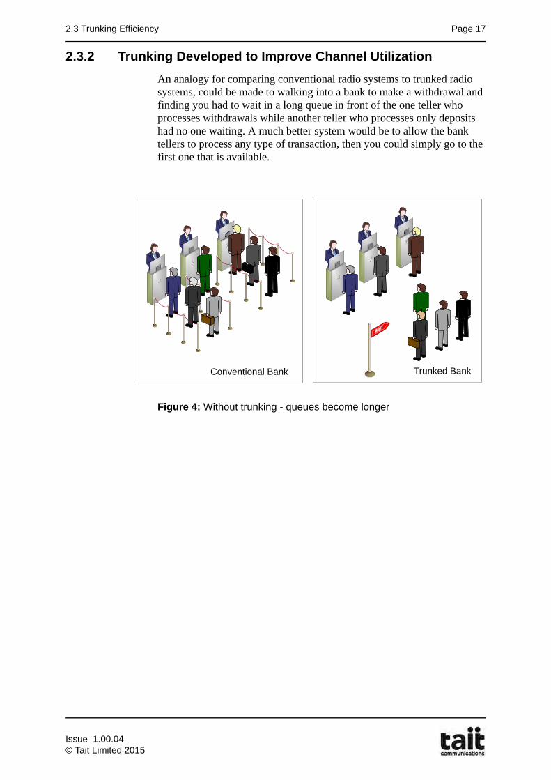
An analogy for comparing conventional radio systems to trunked radio systems, could be made to walking into a bank to make a withdrawal and finding you had to wait in a long queue in front of the one teller who processes withdrawals while another teller who processes only deposits had no one waiting. A much better system would be to allow the bank tellers to process any type of transaction, then you could simply go to the first one that is available.
Figure 4: Without trunking - queues become longer
Conventional Bank Trunked Bank
Issue 1.00.04© Tait Limited 2015
Page 18 Chapter 2: Introduction to Trunking
2.3.3 Origin of Trunking
Trunked Phone Lines
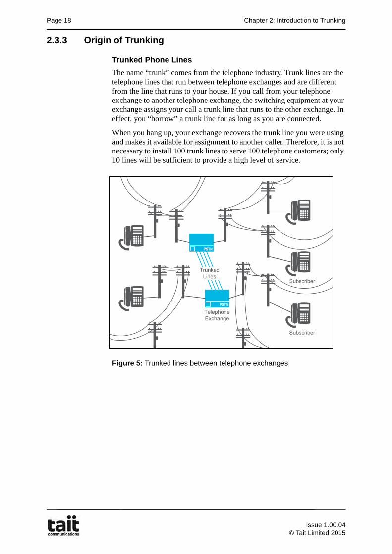
The name “trunk” comes from the telephone industry. Trunk lines are the telephone lines that run between telephone exchanges and are different from the line that runs to your house. If you call from your telephone exchange to another telephone exchange, the switching equipment at your exchange assigns your call a trunk line that runs to the other exchange. In effect, you “borrow” a trunk line for as long as you are connected.
When you hang up, your exchange recovers the trunk line you were using and makes it available for assignment to another caller. Therefore, it is not necessary to install 100 trunk lines to serve 100 telephone customers; only 10 lines will be sufficient to provide a high level of service.
Figure 5: Trunked lines between telephone exchanges
����
����
�����������
�� ��������������
����������
����������
Issue 1.00.04
© Tait Limited 2015
2.4 Trunked Radio Systems Page 19
2.4 Trunked Radio Systems
Advances in technology provided a break-through in the form of low cost single chip microprocessors. This allowed the concept of trunking to be applied to mobile radio systems. A better name for trunked radio would be “computer aided radio” as it is the application of microprocessors and synthesizers that enables Trunked Radio Systems to share a pool of radio channels between many groups of users.
A trunked radio system has:
• A Control Channel that is used to send messages between the trunked system and the subscriber units.
• A number of Traffic Channels used for the voice calls.
Each group of users gets the exclusive use of a Traffic Channel for the duration of their call. No other groups are using the channel at the same time. A call has different meanings depending of the type of trunking:
• In Transmission Trunking, a call is a single over (press of the PTT).
• Quasi-Transmission Trunking uses a “Hang Time”. A reply within the hang time is part of the same call and uses the same traffic channel.
• In Message Trunking, a call may consist of several overs (a conversation) and continues until one of the users presses a button to end the call. It is typically used for individual calls.
To set up a voice call on a trunking system:
• A subscriber presses the PTT, and the subscriber unit transmits a call request to the system via the control channel.
• The system sends, via the control channel, a Channel Grant message to the calling subscriber unit and the subscriber unit (or group of subscriber units) that they called.
• All the subscriber units involved in the call then tune to the designated traffic channel, and the call takes place.
Issue 1.00.04© Tait Limited 2015
Page 20 Chapter 2: Introduction to Trunking
2.4.1 Trunked Radio Example
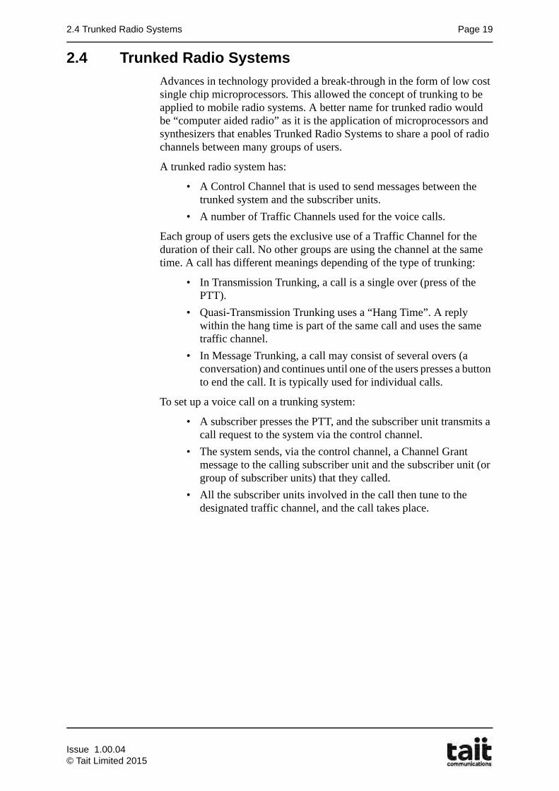
A trunked site has a control channel and a number of traffic channels. The number of traffic channels required depends on the number of groups using the system and the number of calls taking place. In this simple example there are only two traffic channels, where on a real network there may be more to handle the required call capacity. There may be hundreds of subscribers on a trunked system but for simplicity this example shows just 11 subscribers. The subscribers consist of different groups or teams - in this example there are fire trucks, ambulances, police cars and highway patrol cars.
Trunking allows all these different user groups to share the same two traffic channels. In the picture below a call is in progress between the two fire trucks and the system has assigned Channel A for this call.
Issue 1.00.04
© Tait Limited 2015
2.4 Trunked Radio Systems Page 21
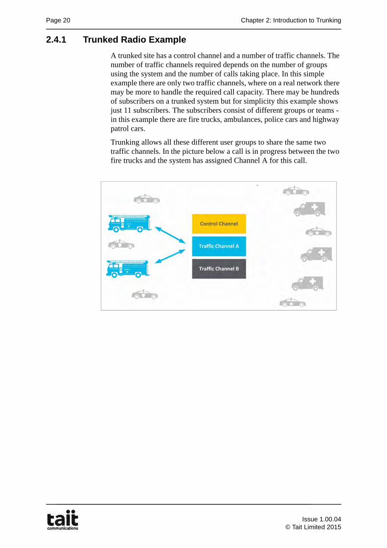
If one of the ambulances wanted to talk to the other ambulances, then when they make their call, the subscriber unit would use the control channel to send a request for a traffic channel to the system. The system would send a message back, which automatically directs all the ambulances to the available traffic channel in this case Channel B.
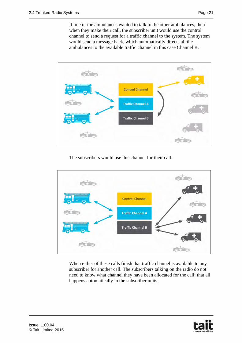
The subscribers would use this channel for their call.
When either of these calls finish that traffic channel is available to any subscriber for another call. The subscribers talking on the radio do not need to know what channel they have been allocated for the call; that all happens automatically in the subscriber units.
Issue 1.00.04© Tait Limited 2015
Page 22 Chapter 2: Introduction to Trunking
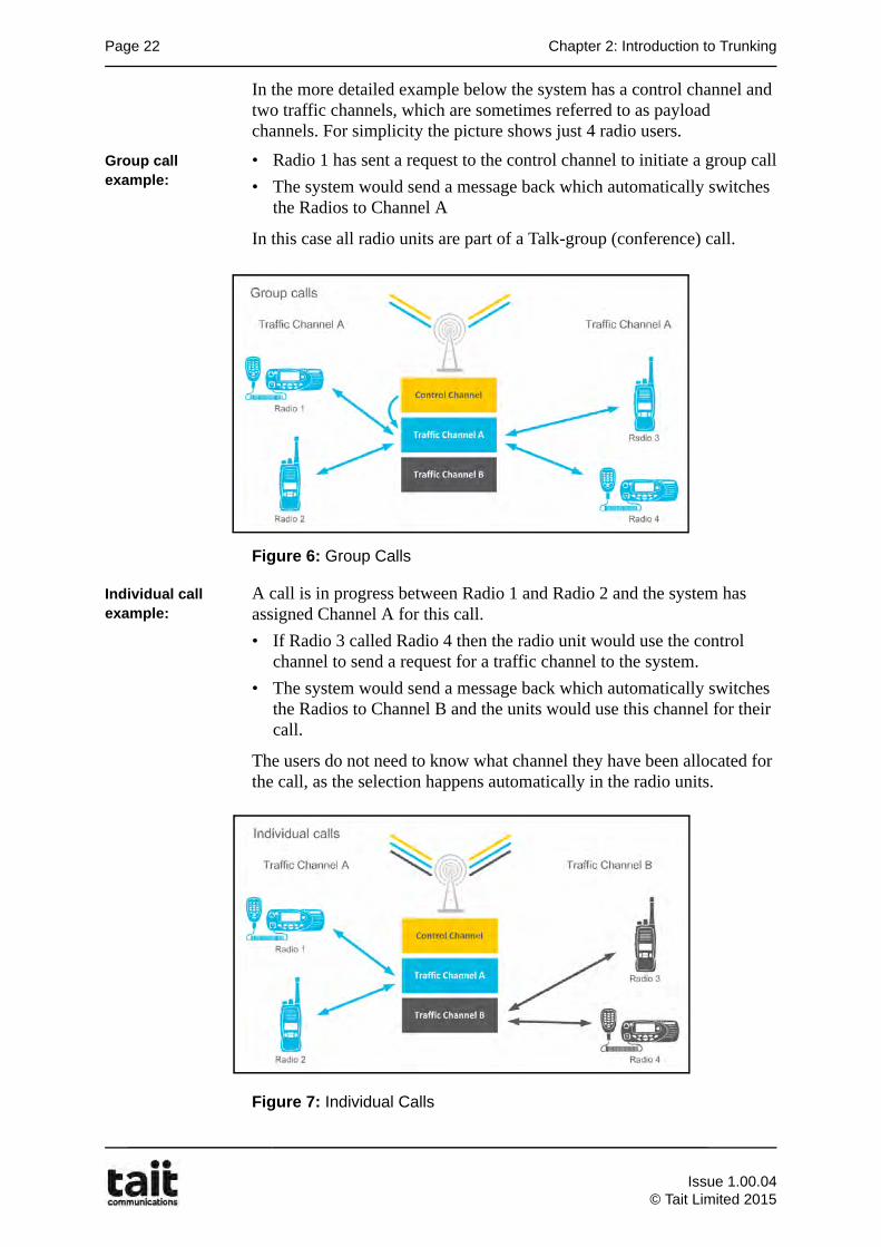
In the more detailed example below the system has a control channel and two traffic channels, which are sometimes referred to as payload channels. For simplicity the picture shows just 4 radio users.
Group call example:
• Radio 1 has sent a request to the control channel to initiate a group call
• The system would send a message back which automatically switches the Radios to Channel A
In this case all radio units are part of a Talk-group (conference) call.
Figure 6: Group Calls
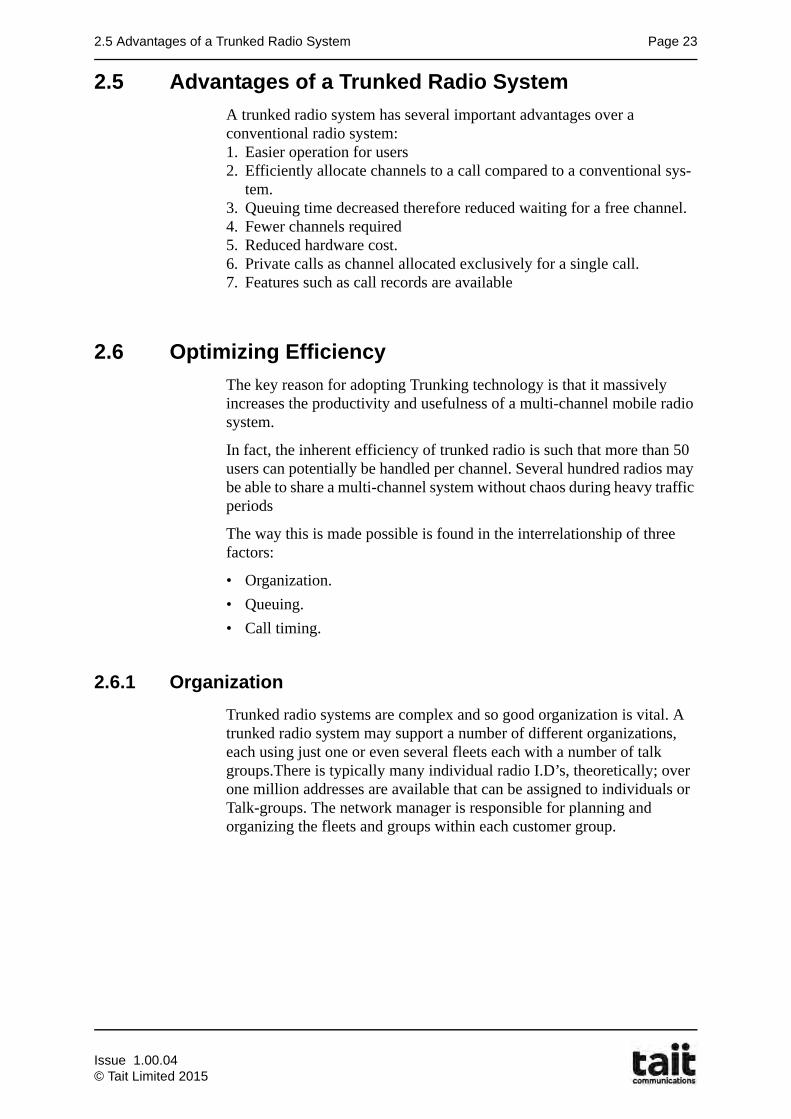
Individual call example:
A call is in progress between Radio 1 and Radio 2 and the system has assigned Channel A for this call.
• If Radio 3 called Radio 4 then the radio unit would use the control channel to send a request for a traffic channel to the system.
• The system would send a message back which automatically switches the Radios to Channel B and the units would use this channel for their call.
The users do not need to know what channel they have been allocated for the call, as the selection happens automatically in the radio units.
Figure 7: Individual Calls
Issue 1.00.04
© Tait Limited 2015
2.5 Advantages of a Trunked Radio System Page 23
2.5 Advantages of a Trunked Radio System
A trunked radio system has several important advantages over a conventional radio system:1. Easier operation for users2. Efficiently allocate channels to a call compared to a conventional sys-
tem.3. Queuing time decreased therefore reduced waiting for a free channel.4. Fewer channels required5. Reduced hardware cost.6. Private calls as channel allocated exclusively for a single call.7. Features such as call records are available
2.6 Optimizing Efficiency
The key reason for adopting Trunking technology is that it massively increases the productivity and usefulness of a multi-channel mobile radio system.
In fact, the inherent efficiency of trunked radio is such that more than 50 users can potentially be handled per channel. Several hundred radios may be able to share a multi-channel system without chaos during heavy traffic periods
The way this is made possible is found in the interrelationship of three factors:
• Organization.
• Queuing.
• Call timing.
2.6.1 Organization
Trunked radio systems are complex and so good organization is vital. A trunked radio system may support a number of different organizations, each using just one or even several fleets each with a number of talk groups.There is typically many individual radio I.D’s, theoretically; over one million addresses are available that can be assigned to individuals or Talk-groups. The network manager is responsible for planning and organizing the fleets and groups within each customer group.
Issue 1.00.04© Tait Limited 2015
Page 24 Chapter 2: Introduction to Trunking
2.6.2 Queuing
A “queue” in this instance is a line-up of people wanting to use a two-way radio system. However, it can be applied to almost any situation where people line-up to receive some service. The trunked radio system places callers in a queue when no free channels are available. Queue times are usually short, and in a Tait trunked system, when a free channel is available the call is automatically setup. Access to channels is controlled dynamically. Queuing and channel assignment are handled by the system infrastructure.
2.6.3 Call Timing
Mobile radio voice transmission times can often be less than 10 seconds long. With this short transmission time, the trunked system controller can almost always find a frequency that is open for a transmission. The Trunking system controls call times to ensure equal access of users.
Issue 1.00.04
© Tait Limited 2015
3.1 Learning Outcomes Page 25
Chapter 3Network Architecture
3.1 Learning Outcomes
Upon completion of this chapter, you will be able to do the following:
• Identify and explain the purpose of the key components of a TaitNet DMR Trunked network.
• Illustrate a typical DMR network.
• List DMR network elements.
• Explain why IP was chosen as the method of moving voice and data.
• Explain how the architecture scaled to suit customer requirements.
• Describe DMR site equipment and the different system configurations.
• Describe DMR node architecture.
• Describe DMR network gateways.
• Explain how dispatch consoles can be connected to the network and list the typical functions provided.
• Explain how conventional radio systems can be connected to the DMR network.
• Explain how telephone systems can be connected to the DMR network
• List DMR network management elements.
• Identify DMR mobile and portable subscriber units.
• Explain how voice recorders can be connected to the DMR network.
Issue 1.00.04© Tait Limited 2015
Page 26 Chapter 3: Network Architecture
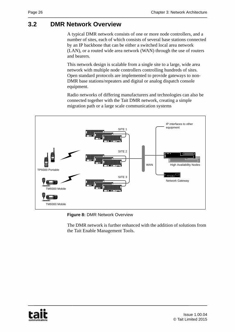
3.2 DMR Network Overview
A typical DMR network consists of one or more node controllers, and a number of sites, each of which consists of several base stations connected by an IP backbone that can be either a switched local area network (LAN), or a routed wide area network (WAN) through the use of routers and bearers.
This network design is scalable from a single site to a large, wide area network with multiple node controllers controlling hundreds of sites. Open standard protocols are implemented to provide gateways to non-DMR base stations/repeaters and digital or analog dispatch console equipment.
Radio networks of differing manufacturers and technologies can also be connected together with the Tait DMR network, creating a simple migration path or a large scale communication systems
Figure 8: DMR Network Overview
The DMR network is further enhanced with the addition of solutions from the Tait Enable Management Tools.
TM9300 Mobile
TM9300 Mobile
TP9300 Portable
High Availability Nodes
Network Gateway
IP interfaces to other equipment
WAN
SITE 1
SITE 2
SITE 3
Issue 1.00.04
© Tait Limited 2015
3.3 DMR Network Elements Page 27
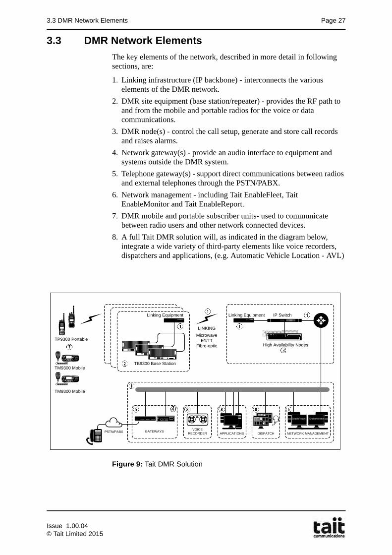
3.3 DMR Network Elements
The key elements of the network, described in more detail in following sections, are:
1. Linking infrastructure (IP backbone) - interconnects the various elements of the DMR network.
2. DMR site equipment (base station/repeater) - provides the RF path to and from the mobile and portable radios for the voice or data communications.
3. DMR node(s) - control the call setup, generate and store call records and raises alarms.
4. Network gateway(s) - provide an audio interface to equipment and systems outside the DMR system.
5. Telephone gateway(s) - support direct communications between radios and external telephones through the PSTN/PABX.
6. Network management - including Tait EnableFleet, Tait EnableMonitor and Tait EnableReport.
7. DMR mobile and portable subscriber units- used to communicate between radio users and other network connected devices.
8. A full Tait DMR solution will, as indicated in the diagram below, integrate a wide variety of third-party elements like voice recorders, dispatchers and applications, (e.g. Automatic Vehicle Location - AVL)
Figure 9: Tait DMR Solution
TM9300 Mobile
TM9300 Mobile
TP9300 Portable
VOICE RECORDER APPLICATIONS DISPATCH NETWORK MANAGEMENT
EnableReport EnableMonitor
LINKING
High Availability Nodes
IP SwitchLinking Equipment
TB9300 Base Station
MicrowaveE1/T1
Fibre-optic
GATEWAYSPSTN/PABX
Linking Equipment
Issue 1.00.04© Tait Limited 2015
Page 28 Chapter 3: Network Architecture
3.4 Linking Infrastructure (IP Backbone)
The DMR trunked network connects the radio sites together using Internet Protocol (IP).
The advantages of using an IP:
Flexibility
• Fault-tolerant packet-switched connection less architecture
• Scalable - easy to meet future requirements
• Secure
Reduction in costs
• Reduce bandwidth consumption by using high-performance compression algorithms
• Lower line costs, fully redundant ring architecture can be used versus a hub and spoke plan
• Lower maintenance costs as only one infrastructure for data and voice needs to be maintained
Multiplexing voice and data
• Lower maintenance costs as only one infrastructure for data and voice needs to be maintained
• Network convergence
• Quality of Service (QoS)
• Web enabled applications and interfaces for simple open network management
Issue 1.00.04
© Tait Limited 2015
3.5 DMR Site Equipment Page 29
3.5 DMR Site Equipment
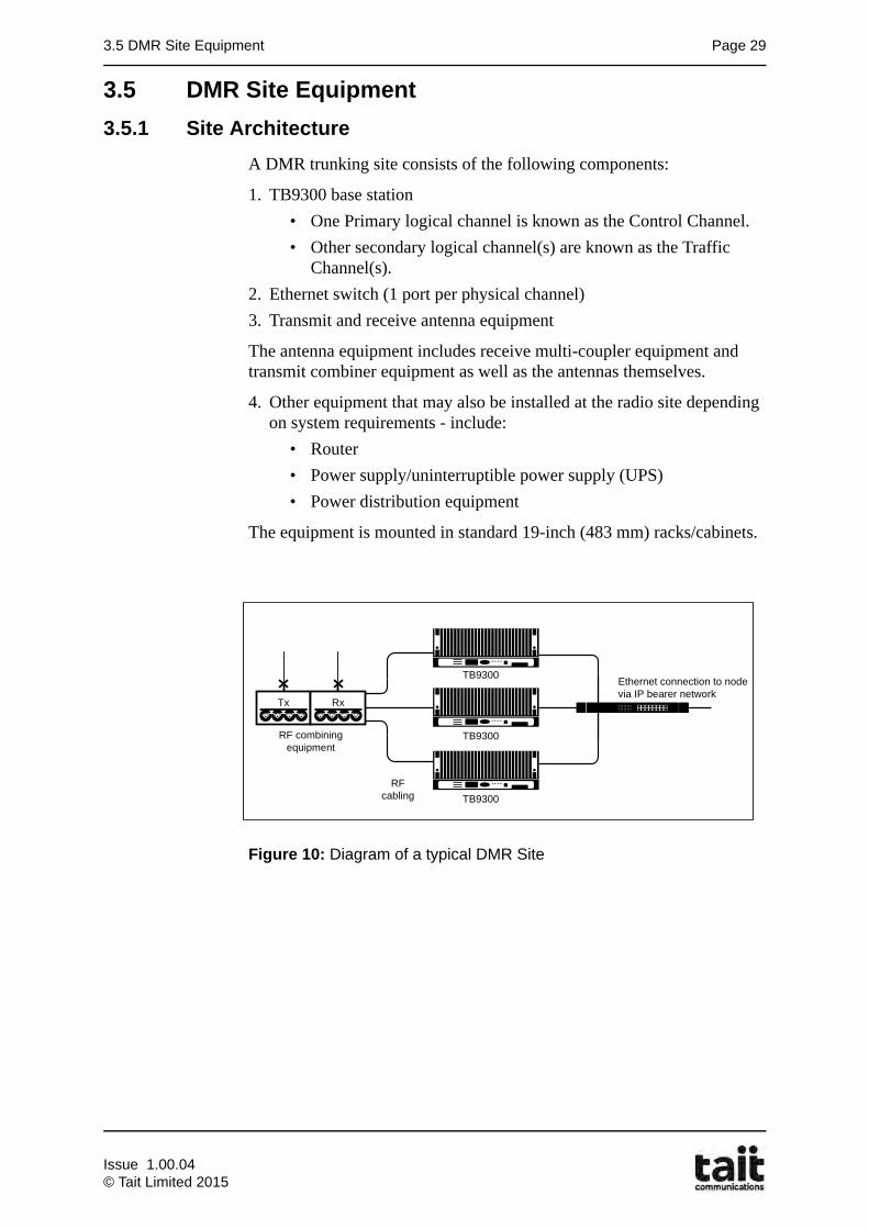
3.5.1 Site Architecture
A DMR trunking site consists of the following components:
1. TB9300 base station
• One Primary logical channel is known as the Control Channel.
• Other secondary logical channel(s) are known as the Traffic Channel(s).
2. Ethernet switch (1 port per physical channel)
3. Transmit and receive antenna equipment
The antenna equipment includes receive multi-coupler equipment and transmit combiner equipment as well as the antennas themselves.
4. Other equipment that may also be installed at the radio site depending on system requirements - include:
• Router
• Power supply/uninterruptible power supply (UPS)
• Power distribution equipment
The equipment is mounted in standard 19-inch (483 mm) racks/cabinets.
Figure 10: Diagram of a typical DMR Site
RFcabling
Ethernet connection to node via IP bearer network
RF combining equipment
Tx Rx
TB9300
TB9300
TB9300
Issue 1.00.04© Tait Limited 2015
Page 30 Chapter 3: Network Architecture
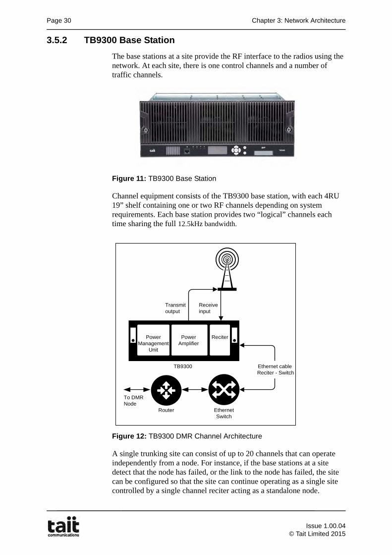
3.5.2 TB9300 Base Station
The base stations at a site provide the RF interface to the radios using the network. At each site, there is one control channels and a number of traffic channels.
Figure 11: TB9300 Base Station
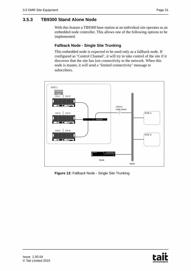
Channel equipment consists of the TB9300 base station, with each 4RU 19” shelf containing one or two RF channels depending on system requirements. Each base station provides two “logical” channels each time sharing the full 12.5kHz bandwidth.
Figure 12: TB9300 DMR Channel Architecture
A single trunking site can consist of up to 20 channels that can operate independently from a node. For instance, if the base stations at a site detect that the node has failed, or the link to the node has failed, the site can be configured so that the site can continue operating as a single site controlled by a single channel reciter acting as a standalone node.
Power Management
Unit
Power Amplifier
Ethernet Switch
TB9300
Ethernet Interface cable between
TB9300 & Switch
Rx input
Tx output
Router
Reciter(Receiver
+Exciter)
Power Amplifier
ReciterPowerManagement
Unit
Transmit output
Receiveinput
Ethernet Switch
Router
Ethernet cableReciter - Switch
To DMRNode
TB9300
Issue 1.00.04
© Tait Limited 2015
3.5 DMR Site Equipment Page 31
3.5.3 TB9300 Stand Alone Node
With this feature a TB9300 base station at an individual site operates as an embedded node controller. This allows one of the following options to be implemented.
Fallback Node - Single Site Trunking
This embedded node is expected to be used only as a fallback node. If configured as ‘Control Channel’, it will try to take control of the site if it discovers that the site has lost connectivity to the network. When this node is master, it will send a ‘limited connectivity’ message to subscribers.
Figure 13: Fallback Node - Single Site Trunking
SITE 1
CH 1 CH 2
CH 3 CH 4
CH 5 CH 6
Link to node down
node
embedded
Node
WAN
SITE 2
SITE 3
Issue 1.00.04© Tait Limited 2015
Page 32 Chapter 3: Network Architecture
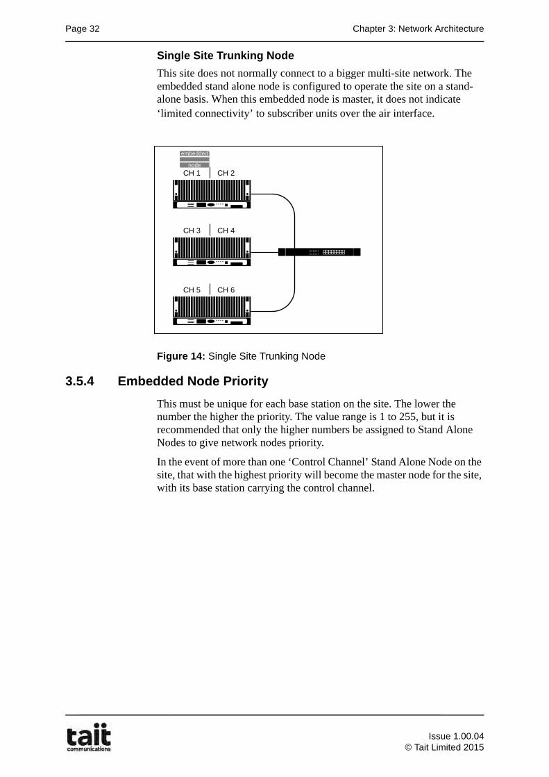
Single Site Trunking Node
This site does not normally connect to a bigger multi-site network. The embedded stand alone node is configured to operate the site on a stand-alone basis. When this embedded node is master, it does not indicate ‘limited connectivity’ to subscriber units over the air interface.
Figure 14: Single Site Trunking Node
3.5.4 Embedded Node Priority
This must be unique for each base station on the site. The lower the number the higher the priority. The value range is 1 to 255, but it is recommended that only the higher numbers be assigned to Stand Alone Nodes to give network nodes priority.
In the event of more than one ‘Control Channel’ Stand Alone Node on the site, that with the highest priority will become the master node for the site, with its base station carrying the control channel.
CH 1 CH 2
CH 3 CH 4
CH 5 CH 6
node
embedded
Issue 1.00.04
© Tait Limited 2015
3.6 DMR Node Architecture Page 33
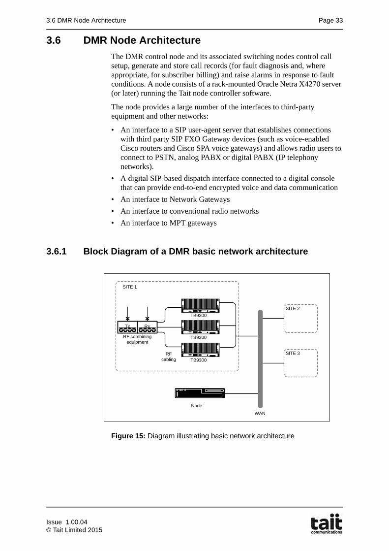
3.6 DMR Node Architecture
The DMR control node and its associated switching nodes control call setup, generate and store call records (for fault diagnosis and, where appropriate, for subscriber billing) and raise alarms in response to fault conditions. A node consists of a rack-mounted Oracle Netra X4270 server (or later) running the Tait node controller software.
The node provides a large number of the interfaces to third-party equipment and other networks:
• An interface to a SIP user-agent server that establishes connections with third party SIP FXO Gateway devices (such as voice-enabled Cisco routers and Cisco SPA voice gateways) and allows radio users to connect to PSTN, analog PABX or digital PABX (IP telephony networks).
• A digital SIP-based dispatch interface connected to a digital console that can provide end-to-end encrypted voice and data communication
• An interface to Network Gateways
• An interface to conventional radio networks
• An interface to MPT gateways
3.6.1 Block Diagram of a DMR basic network architecture
Figure 15: Diagram illustrating basic network architecture
Node
WAN
SITE 1
RFcabling
RF combining equipment
Tx Rx
TB9300
TB9300
TB9300
SITE 2
SITE 3
Issue 1.00.04© Tait Limited 2015
Page 34 Chapter 3: Network Architecture
3.6.2 Capacity
A Tait DMR network is scalable from a single site with one base station to a large, wide area network with multiple nodes, 1000 base stations and 300 network gateways. One node is needed for every 100 talk paths in the network. One or more additional nodes are desirable for redundancy. Each reciter in a base station provides two voice channels and each gateway a single voice channel. A network can have up to 20 nodes and a maximum of 100 sites A table summarizing the DMR network dimensions can be found at the end of this section.
3.6.3 DMR Node Operation
In an DMR network, a node has two functions:
• a control node
• a switching node
There is only one control node in a network. In a multi-node network, the lowest numbered node is the control node. It validates all call requests, sets up and clears down all calls, and sends call control messages and routing instructions to the base stations. All nodes in the network can also function as switching nodes. The switching nodes are used to transfer audio data between the base stations (as per the control node instructions). In a single-node network, the node fulfills both functions. Having more than one node in an DMR network is advantageous, as:
• higher numbers of nodes spreads the load of voice traffic, keeping queue times down
• if the control node fails, the next lowest numbered switching node will take over as the control node
3.6.4 Node Equipment
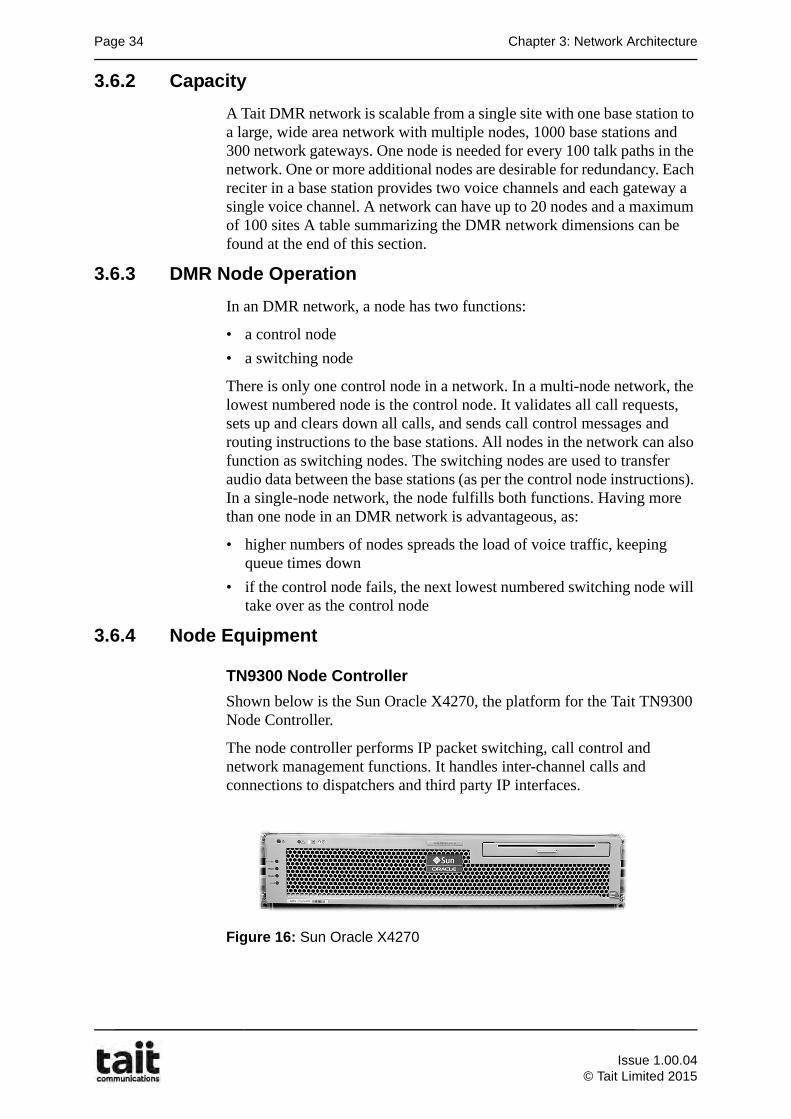
TN9300 Node Controller
Shown below is the Sun Oracle X4270, the platform for the Tait TN9300 Node Controller.
The node controller performs IP packet switching, call control and network management functions. It handles inter-channel calls and connections to dispatchers and third party IP interfaces.
Figure 16: Sun Oracle X4270
Issue 1.00.04
© Tait Limited 2015
3.6 DMR Node Architecture Page 35
The node carries out the following functions:• Setting up calls. This includes allocating logical channels to calls.
• Switching voice packets between interfaces. The node receives these voice packets from base stations and SIP (Session Initiation Protocol) interfaces and switches them to all the logical channels involved in the call. Where multiple streams are received at the same time, the node selects a single stream for forwarding to the required destinations.
• Receiving radio registrations, storing them in its registration database and using them when setting up calls.
• Maintaining a validation database and using this to decide whether to permit a call request.
• Generating and storing call records. These are used for fault diagnosis and may be used for subscriber billing.
• Raising alarms in response to fault conditions.
• Providing a SIP user-agent server that controls SIP gateways. This control is needed for calls involving telephone users and dispatch consoles respectively.
Smaller networks only need one node (or two for redundancy), but larger networks will have several, with one being primary. The control node maintains the validation and registration databases and keeps the other nodes up-to-date with any changes. Once the control node has set up a call, it delegates the switching of the call's voice packets to one of the other nodes.
If the control node fails, the switching node with the lowest node number automatically takes its place.
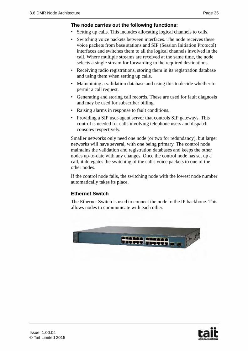
Ethernet Switch
The Ethernet Switch is used to connect the node to the IP backbone. This allows nodes to communicate with each other.
Issue 1.00.04© Tait Limited 2015
Page 36 Chapter 3: Network Architecture
3.7 DMR Network Gateways
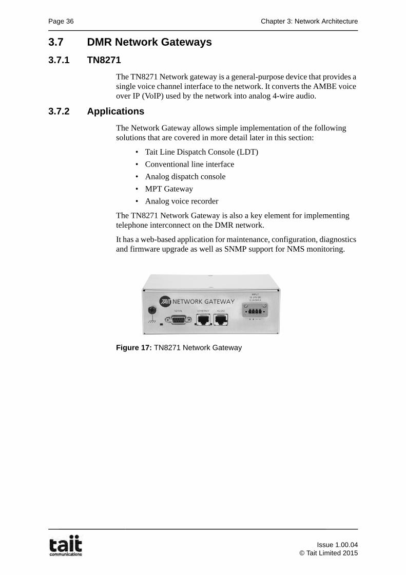
3.7.1 TN8271
The TN8271 Network gateway is a general-purpose device that provides a single voice channel interface to the network. It converts the AMBE voice over IP (VoIP) used by the network into analog 4-wire audio.
3.7.2 Applications
The Network Gateway allows simple implementation of the following solutions that are covered in more detail later in this section:
• Tait Line Dispatch Console (LDT)
• Conventional line interface
• Analog dispatch console
• MPT Gateway
• Analog voice recorder
The TN8271 Network Gateway is also a key element for implementing telephone interconnect on the DMR network.
It has a web-based application for maintenance, configuration, diagnostics and firmware upgrade as well as SNMP support for NMS monitoring.
Figure 17: TN8271 Network Gateway
Issue 1.00.04
© Tait Limited 2015
3.7 DMR Network Gateways Page 37
3.7.3 T1542 Line Dispatch Terminal
The Tait T1542 Line Dispatch Terminal (LDT) is a PC based dispatch consoles that provides a simple yet powerful interface into the Tait TN9300 DMR network.
With the LDT software and associated hardware, central dispatch operations can effectively communicate with a large number of radio users. The features and functions of the LDT include:
• Simple configurable user interface
• Identify multiple simultaneous emergency and non-emergency calls from multiple users
• Displays caller/talker ID
• Display historical and missed calls
• simple talkgroup calling
• simple talkgroup monitor/un-monitor
• call hold
• call conferencing
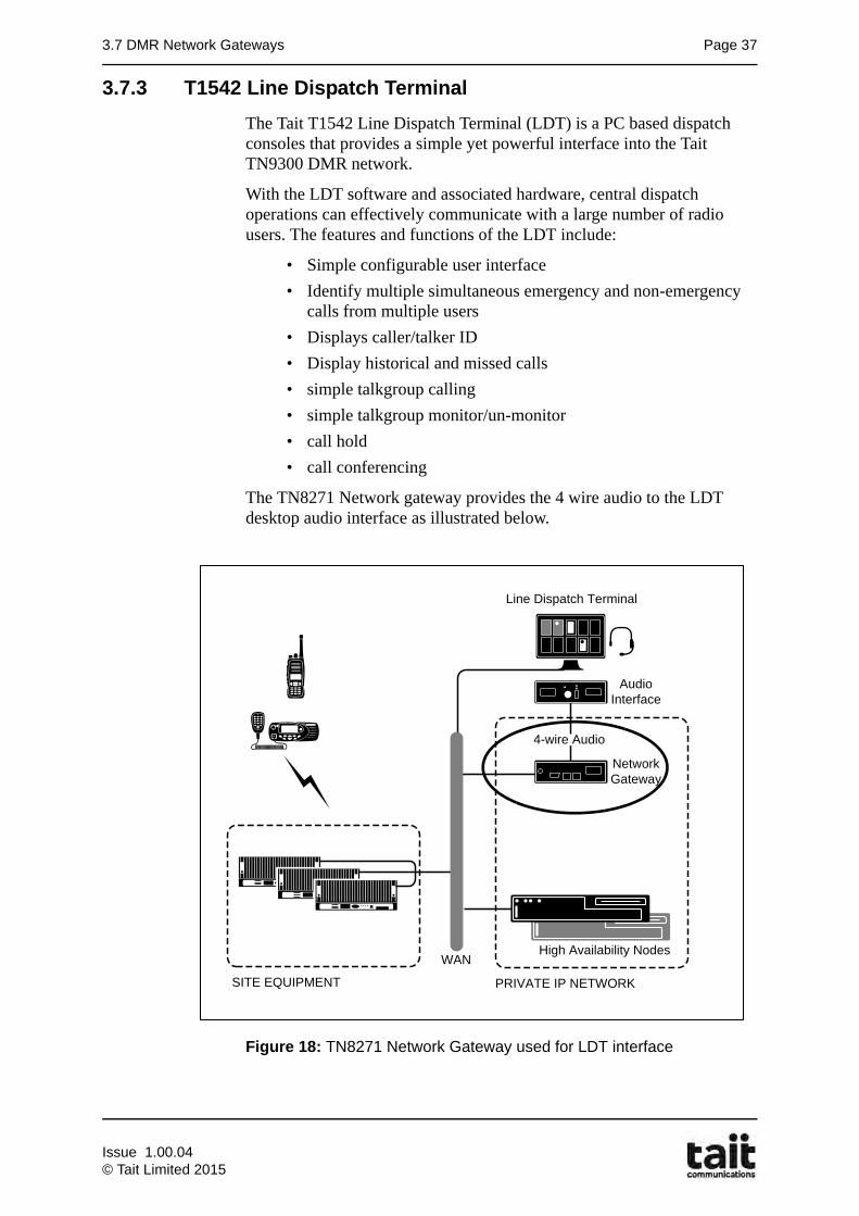
The TN8271 Network gateway provides the 4 wire audio to the LDT desktop audio interface as illustrated below.
Figure 18: TN8271 Network Gateway used for LDT interface
High Availability NodesWAN
4-wire Audio
PRIVATE IP NETWORK
Line Dispatch Terminal
Network Gateway
AudioInterface
SITE EQUIPMENT
Issue 1.00.04© Tait Limited 2015
Page 38 Chapter 3: Network Architecture
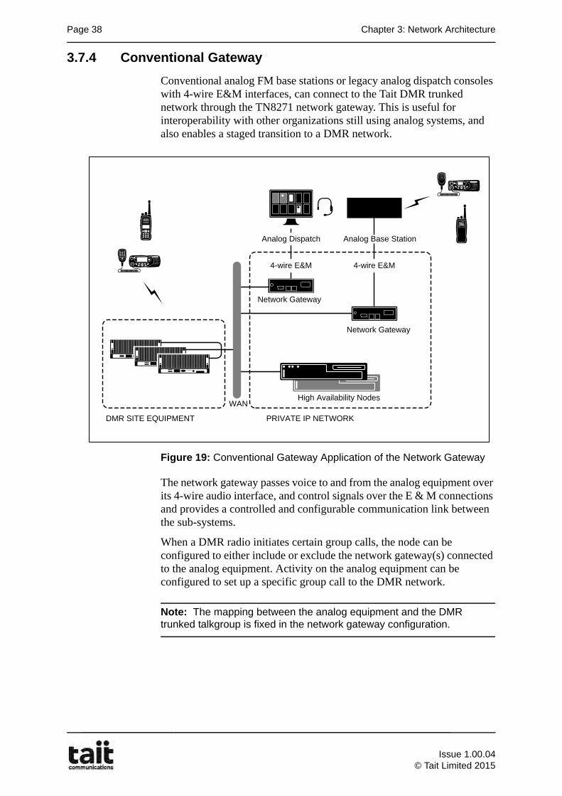
3.7.4 Conventional Gateway
Conventional analog FM base stations or legacy analog dispatch consoles with 4-wire E&M interfaces, can connect to the Tait DMR trunked network through the TN8271 network gateway. This is useful for interoperability with other organizations still using analog systems, and also enables a staged transition to a DMR network.
Figure 19: Conventional Gateway Application of the Network Gateway
The network gateway passes voice to and from the analog equipment over its 4-wire audio interface, and control signals over the E & M connections and provides a controlled and configurable communication link between the sub-systems.
When a DMR radio initiates certain group calls, the node can be configured to either include or exclude the network gateway(s) connected to the analog equipment. Activity on the analog equipment can be configured to set up a specific group call to the DMR network.
Note: The mapping between the analog equipment and the DMR trunked talkgroup is fixed in the network gateway configuration.
High Availability Nodes
Network Gateway
Analog Base Station
WAN
DMR SITE EQUIPMENT
4-wire E&M
PRIVATE IP NETWORK
Analog Dispatch
Network Gateway
4-wire E&M
Issue 1.00.04
© Tait Limited 2015
3.7 DMR Network Gateways Page 39
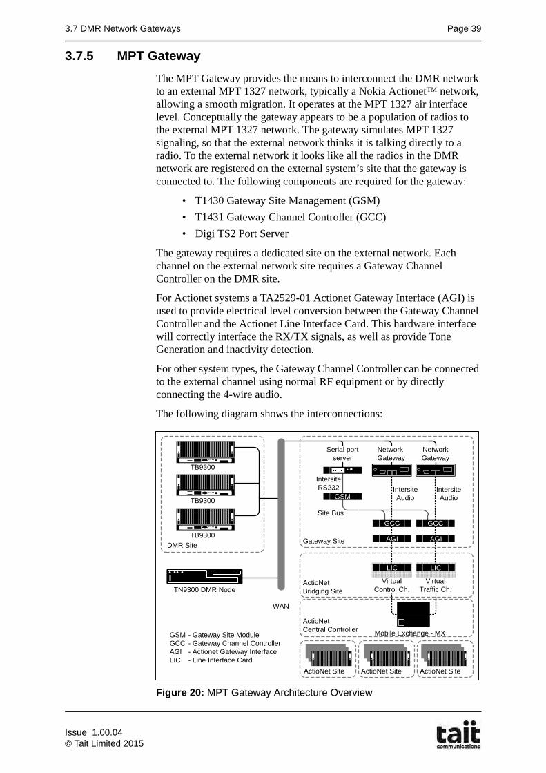
3.7.5 MPT Gateway
The MPT Gateway provides the means to interconnect the DMR network to an external MPT 1327 network, typically a Nokia Actionet™ network, allowing a smooth migration. It operates at the MPT 1327 air interface level. Conceptually the gateway appears to be a population of radios to the external MPT 1327 network. The gateway simulates MPT 1327 signaling, so that the external network thinks it is talking directly to a radio. To the external network it looks like all the radios in the DMR network are registered on the external system’s site that the gateway is connected to. The following components are required for the gateway:
• T1430 Gateway Site Management (GSM)
• T1431 Gateway Channel Controller (GCC)
• Digi TS2 Port Server
The gateway requires a dedicated site on the external network. Each channel on the external network site requires a Gateway Channel Controller on the DMR site.
For Actionet systems a TA2529-01 Actionet Gateway Interface (AGI) is used to provide electrical level conversion between the Gateway Channel Controller and the Actionet Line Interface Card. This hardware interface will correctly interface the RX/TX signals, as well as provide Tone Generation and inactivity detection.
For other system types, the Gateway Channel Controller can be connected to the external channel using normal RF equipment or by directly connecting the 4-wire audio.
The following diagram shows the interconnections:
Figure 20: MPT Gateway Architecture Overview
TN9300 DMR Node
WAN
DMR Site
VirtualTraffic Ch.
Virtual Control Ch.
TB9300
TB9300
TB9300Gateway Site
Serial port server
Network Gateway
Network Gateway
GSM
GCC GCC
AGI
ActioNet Bridging Site
GSM - Gateway Site ModuleGCC - Gateway Channel Controller AGI - Actionet Gateway Interface LIC - Line Interface Card
IntersiteAudio
IntersiteAudio
IntersiteRS232
Site Bus
LIC LIC
AGI
GCC
ActioNet Site
Mobile Exchange - MX
ActioNet Site ActioNet Site
ActioNet Central Controller
Issue 1.00.04© Tait Limited 2015
Page 40 Chapter 3: Network Architecture
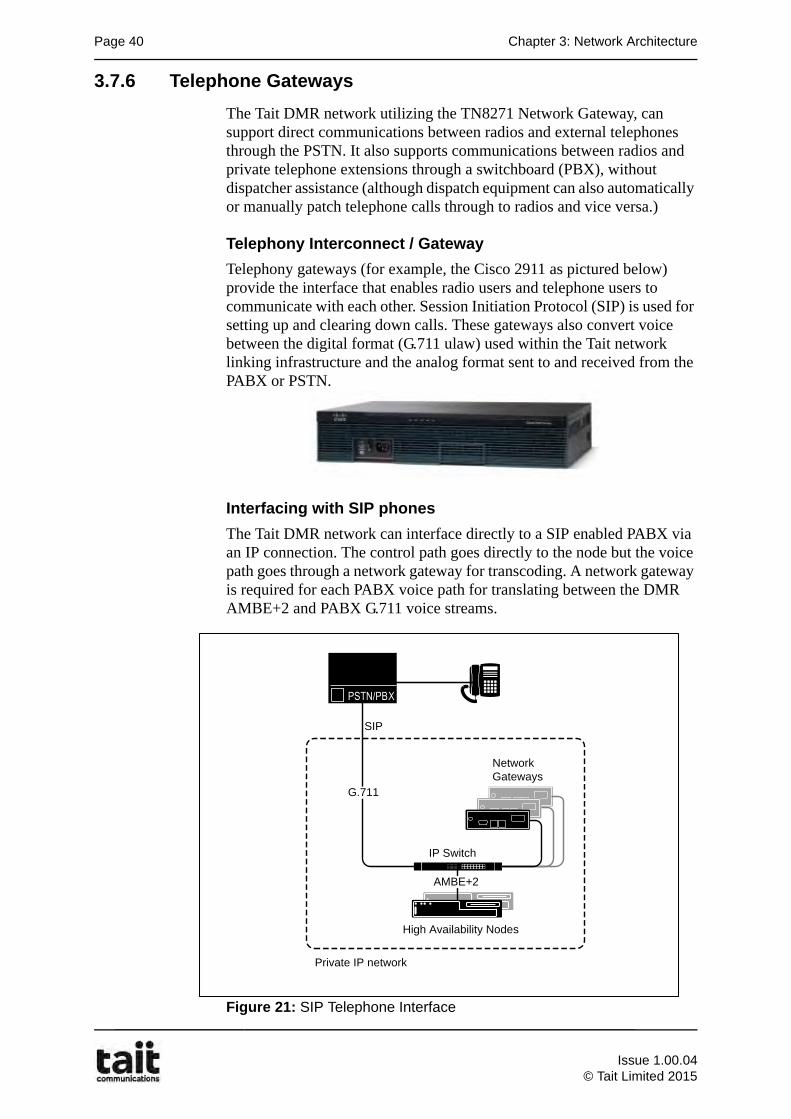
3.7.6 Telephone Gateways
The Tait DMR network utilizing the TN8271 Network Gateway, can support direct communications between radios and external telephones through the PSTN. It also supports communications between radios and private telephone extensions through a switchboard (PBX), without dispatcher assistance (although dispatch equipment can also automatically or manually patch telephone calls through to radios and vice versa.)
Telephony Interconnect / Gateway
Telephony gateways (for example, the Cisco 2911 as pictured below) provide the interface that enables radio users and telephone users to communicate with each other. Session Initiation Protocol (SIP) is used for setting up and clearing down calls. These gateways also convert voice between the digital format (G.711 ulaw) used within the Tait network linking infrastructure and the analog format sent to and received from the PABX or PSTN.
Interfacing with SIP phones
The Tait DMR network can interface directly to a SIP enabled PABX via an IP connection. The control path goes directly to the node but the voice path goes through a network gateway for transcoding. A network gateway is required for each PABX voice path for translating between the DMR AMBE+2 and PABX G.711 voice streams.
Figure 21: SIP Telephone Interface
High Availability Nodes
IP Switch
Network Gateways
PSTN/PBX
SIP
Private IP network
G.711
AMBE+2
Issue 1.00.04
© Tait Limited 2015
3.7 DMR Network Gateways Page 41
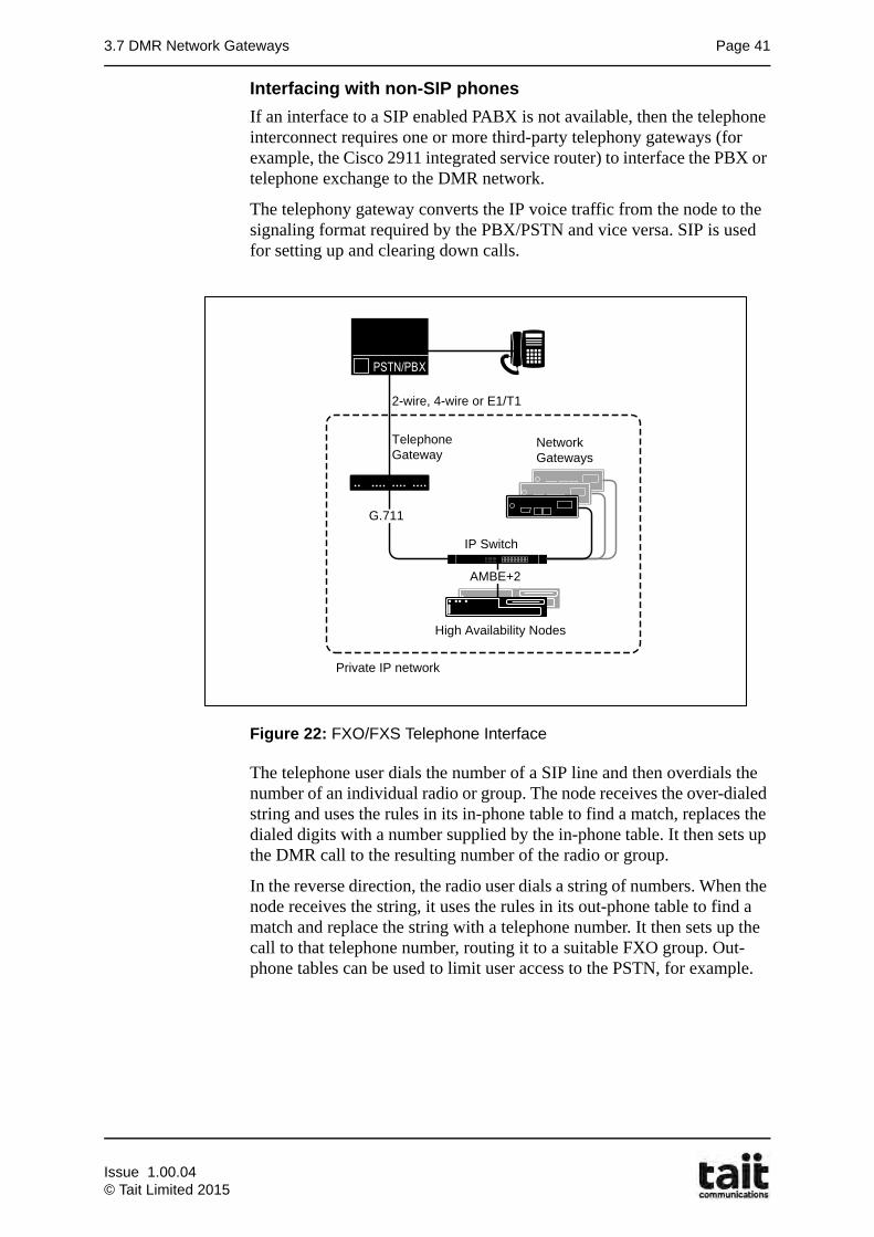
Interfacing with non-SIP phones
If an interface to a SIP enabled PABX is not available, then the telephone interconnect requires one or more third-party telephony gateways (for example, the Cisco 2911 integrated service router) to interface the PBX or telephone exchange to the DMR network.
The telephony gateway converts the IP voice traffic from the node to the signaling format required by the PBX/PSTN and vice versa. SIP is used for setting up and clearing down calls.
Figure 22: FXO/FXS Telephone Interface
The telephone user dials the number of a SIP line and then overdials the number of an individual radio or group. The node receives the over-dialed string and uses the rules in its in-phone table to find a match, replaces the dialed digits with a number supplied by the in-phone table. It then sets up the DMR call to the resulting number of the radio or group.
In the reverse direction, the radio user dials a string of numbers. When the node receives the string, it uses the rules in its out-phone table to find a match and replace the string with a telephone number. It then sets up the call to that telephone number, routing it to a suitable FXO group. Out-phone tables can be used to limit user access to the PSTN, for example.
Telephone Gateway
G.711
High Availability Nodes
IP Switch
Network Gateways
PSTN/PBX
2-wire, 4-wire or E1/T1
Private IP network
AMBE+2
TelephoneGateway
G.711
Issue 1.00.04© Tait Limited 2015
Page 42 Chapter 3: Network Architecture
3.8 DMR Network Management Elements
Tait provides a number of configuration, monitoring and reporting tools to provide effective network management on the DMR radio network.
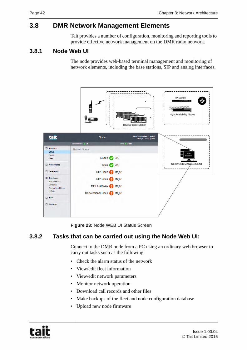
3.8.1 Node Web UI
The node provides web-based terminal management and monitoring of network elements, including the base stations, SIP and analog interfaces.
Figure 23: Node WEB UI Status Screen
3.8.2 Tasks that can be carried out using the Node Web UI:
Connect to the DMR node from a PC using an ordinary web browser to carry out tasks such as the following:
• Check the alarm status of the network
• View/edit fleet information
• View/edit network parameters
• Monitor network operation
• Download call records and other files
• Make backups of the fleet and node configuration database
• Upload new node firmware
NETWORK MANAGEMENT
High Availability Nodes
IP Switch
TB9300 Base Station
Web Browser
Issue 1.00.04
© Tait Limited 2015
3.8 DMR Network Management Elements Page 43
The TB9300 Base Station equipment and the TN8271 Network Gateway also provides web-based terminal management and monitoring to allow:
• maintenance
• configuration
• diagnostics
• calibration
• firmware upgrades
There is therefore no need for an installed application on the network administrator's computer. Because the application is in the node, base stations and Gateways themselves, there are no problems arising from configuration software version incompatibilities.
Network administrators can access the TN9300, any TB9300, and any TN8271 Network Gateway from anywhere on the network, using a secure session with an ordinary web browser. More than one network administrator can monitor network elements at the same time.
Issue 1.00.04© Tait Limited 2015
Page 44 Chapter 3: Network Architecture
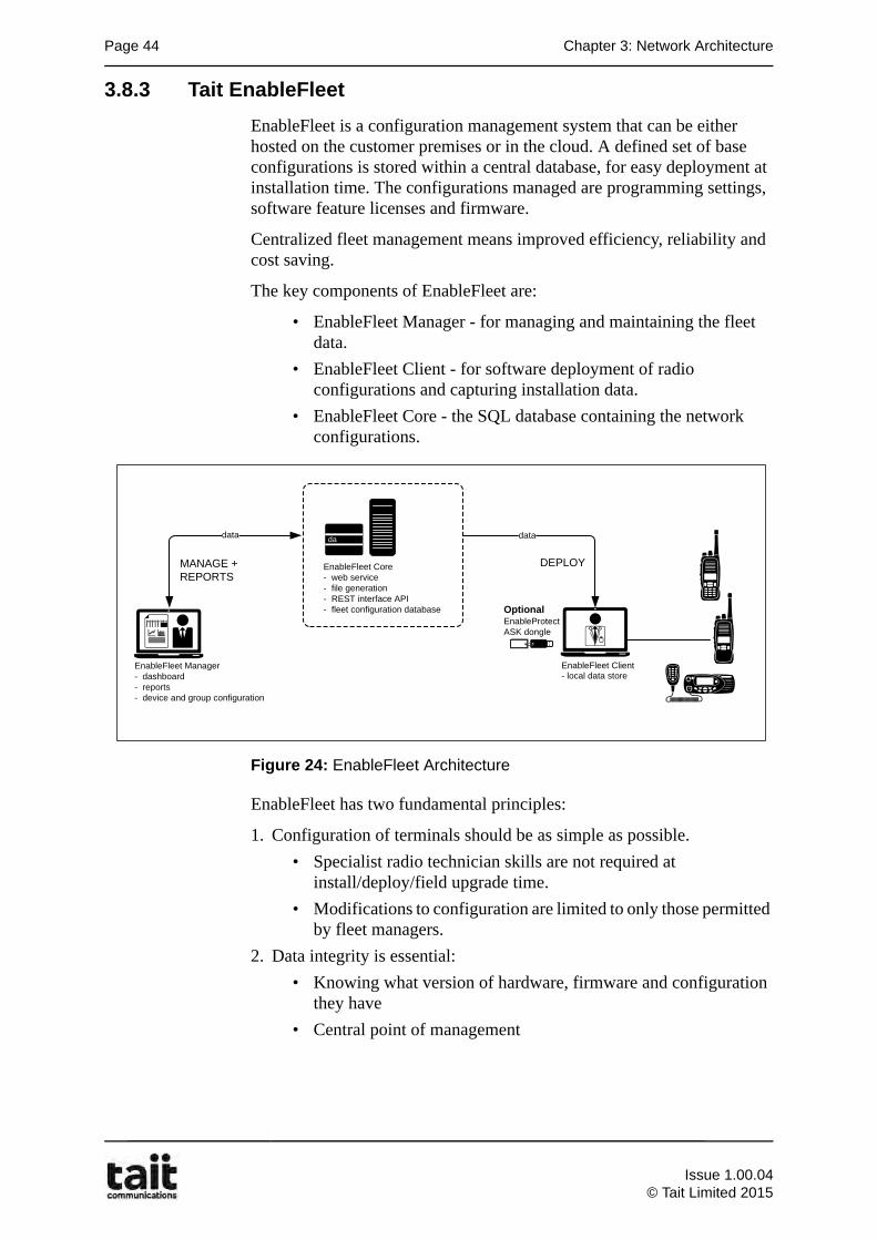
3.8.3 Tait EnableFleet
EnableFleet is a configuration management system that can be either hosted on the customer premises or in the cloud. A defined set of base configurations is stored within a central database, for easy deployment at installation time. The configurations managed are programming settings, software feature licenses and firmware.
Centralized fleet management means improved efficiency, reliability and cost saving.
The key components of EnableFleet are:
• EnableFleet Manager - for managing and maintaining the fleet data.
• EnableFleet Client - for software deployment of radio configurations and capturing installation data.
• EnableFleet Core - the SQL database containing the network configurations.
Figure 24: EnableFleet Architecture
EnableFleet has two fundamental principles:
1. Configuration of terminals should be as simple as possible.
• Specialist radio technician skills are not required at install/deploy/field upgrade time.
• Modifications to configuration are limited to only those permitted by fleet managers.
2. Data integrity is essential:
• Knowing what version of hardware, firmware and configuration they have
• Central point of management
datadata
EnableFleet Manager- dashboard- reports- device and group configuration
database
EnableFleet Core- web service- file generation- REST interface API- fleet configuration database Optional
EnableProtectASK dongle
EnableFleet Client- local data store
MANAGE + REPORTS
DEPLOY
Issue 1.00.04
© Tait Limited 2015
3.8 DMR Network Management Elements Page 45
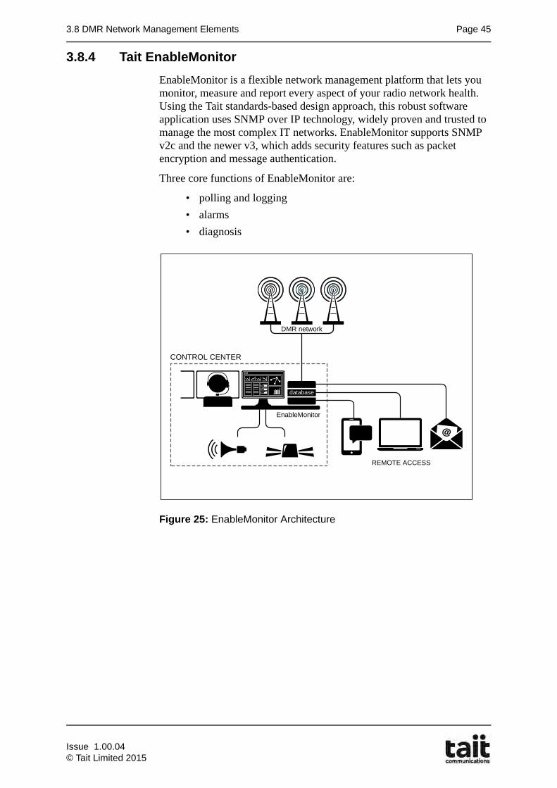
3.8.4 Tait EnableMonitor
EnableMonitor is a flexible network management platform that lets you monitor, measure and report every aspect of your radio network health. Using the Tait standards-based design approach, this robust software application uses SNMP over IP technology, widely proven and trusted to manage the most complex IT networks. EnableMonitor supports SNMP v2c and the newer v3, which adds security features such as packet encryption and message authentication.
Three core functions of EnableMonitor are:
• polling and logging
• alarms
• diagnosis
Figure 25: EnableMonitor Architecture
database
CONTROL CENTER
DMR network
EnableMonitor
REMOTE ACCESS
Issue 1.00.04© Tait Limited 2015
Page 46 Chapter 3: Network Architecture
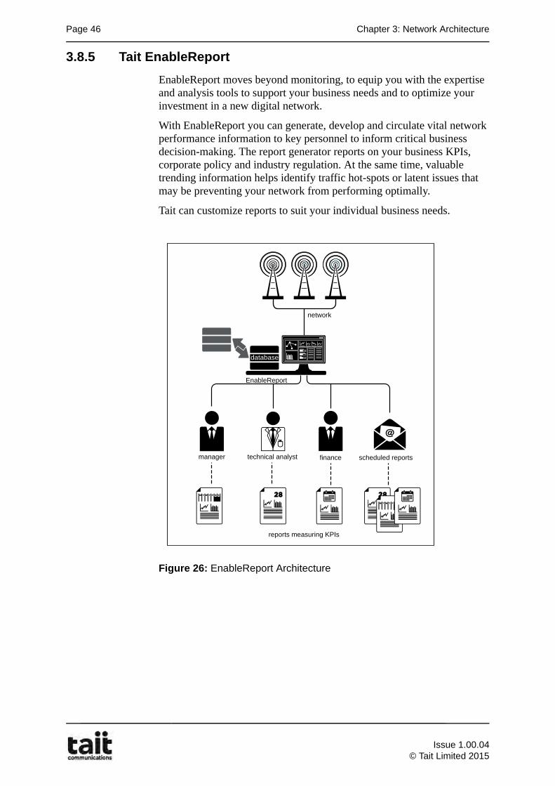
3.8.5 Tait EnableReport
EnableReport moves beyond monitoring, to equip you with the expertise and analysis tools to support your business needs and to optimize your investment in a new digital network.
With EnableReport you can generate, develop and circulate vital network performance information to key personnel to inform critical business decision-making. The report generator reports on your business KPIs, corporate policy and industry regulation. At the same time, valuable trending information helps identify traffic hot-spots or latent issues that may be preventing your network from performing optimally.
Tait can customize reports to suit your individual business needs.
Figure 26: EnableReport Architecture
network
EnableReport
database
technical analyst financemanager scheduled reports
reports measuring KPIs
Issue 1.00.04
© Tait Limited 2015

3.9 DMR Mobile and Portable Subscriber Units Page 47
3.9 DMR Mobile and Portable Subscriber Units
The TP9300 TM9300 series is a range of high-performance microprocessor-controlled DMR portable and mobile radios for voice and data communication.
Tait DMR radios are designed with group communications in mind. Simple user interfaces and flexible group configurations allow users to maintain reliable communications within their team and also to other teams or individuals when required. Group membership can be controlled both by the radio operator and by a network administrator.
TP9300 Tait DMR portable radios
TM9355 TP9360TP9355
Hand-Held Control Head (HHCH)
TM9300 Tait DMR mobile radio
Issue 1.00.04© Tait Limited 2015
Page 48 Chapter 3: Network Architecture
3.10 DMR Voice Recorder
The TN9300's Voice Recorder Protocol (VRP) enables connection of VRP compliant Voice Recorders to the TN9300 for recording Unit to Unit Calls and Group Calls including SIP, AIS and DIP.
3.11 Eventide NexLog Voice Recorder
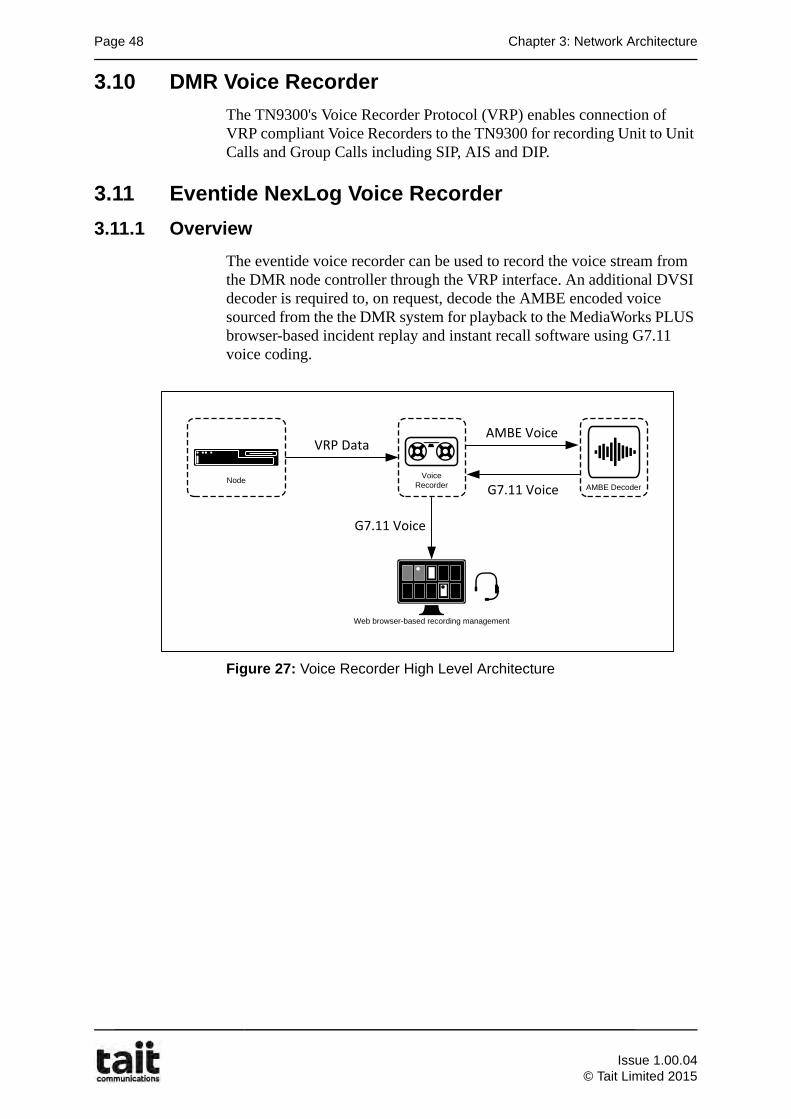
3.11.1 Overview
The eventide voice recorder can be used to record the voice stream from the DMR node controller through the VRP interface. An additional DVSI decoder is required to, on request, decode the AMBE encoded voice sourced from the the DMR system for playback to the MediaWorks PLUS browser-based incident replay and instant recall software using G7.11 voice coding.
Figure 27: Voice Recorder High Level Architecture
Node
VRP Data
AMBE DecoderVoice
Recorder
AMBE Voice
G7.11 Voice
G7.11 Voice
Web browser-based recording management
Issue 1.00.04
© Tait Limited 2015
3.11 Eventide NexLog Voice Recorder Page 49
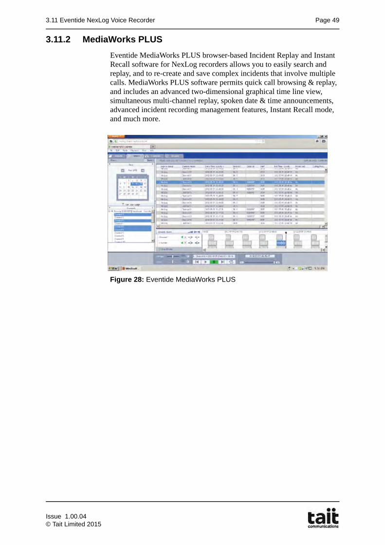
3.11.2 MediaWorks PLUS
Eventide MediaWorks PLUS browser-based Incident Replay and Instant Recall software for NexLog recorders allows you to easily search and replay, and to re-create and save complex incidents that involve multiple calls. MediaWorks PLUS software permits quick call browsing & replay, and includes an advanced two-dimensional graphical time line view, simultaneous multi-channel replay, spoken date & time announcements, advanced incident recording management features, Instant Recall mode, and much more.
Figure 28: Eventide MediaWorks PLUS
Issue 1.00.04© Tait Limited 2015
Page 50 Chapter 3: Network Architecture
Chapter 3 References
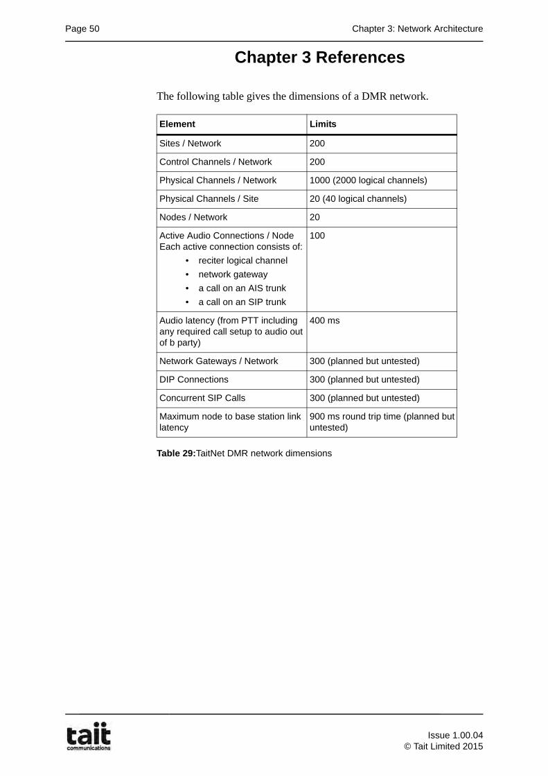
The following table gives the dimensions of a DMR network.
Table 29:TaitNet DMR network dimensions
Element Limits
Sites / Network 200
Control Channels / Network 200
Physical Channels / Network 1000 (2000 logical channels)
Physical Channels / Site 20 (40 logical channels)
Nodes / Network 20
Active Audio Connections / NodeEach active connection consists of:
• reciter logical channel
• network gateway
• a call on an AIS trunk
• a call on an SIP trunk
100
Audio latency (from PTT including any required call setup to audio out of b party)
400 ms
Network Gateways / Network 300 (planned but untested)
DIP Connections 300 (planned but untested)
Concurrent SIP Calls 300 (planned but untested)
Maximum node to base station link latency
900 ms round trip time (planned but untested)
Issue 1.00.04
© Tait Limited 2015
4.1 Learning Outcomes Page 51
Chapter 4Channel Operation and Configuration
4.1 Learning Outcomes
Upon completion of this chapter, you will be able to do the following:
• Describe the concept of logical channels
• Describe channel operation and configuration
• Demonstrate channel numbering calculations
Issue 1.00.04© Tait Limited 2015
Page 52 Chapter 4: Channel Operation and Configuration
4.2 Logical Channels
Communications between sites and radios are performed on radio channels. Each channel consists of a frequency pair, one for transmission and one for reception. DMR being a 2 time slot TDMA standard, introduces the concept of logical channels.
A logical channel is defined as a communication pathway between two or more parties, and represent the interface between the protocol and the radio subsystem. A single RF frequency in a DMR radio system can maintain two independent logical channels.
4.2.1 Logical Channel Categories
The logical channels may be separated into two categories:
• control channel
• the traffic channel (or payload channel)
A radio channel used for Signaling is known as a control channel. A radio channel employed for user communications, i.e. speech or packet data calls, is known as a traffic channel or payload channel.
Each site typically operates a single control channel and multiple traffic channels. For multi-site group calls or intersite individual calls, a traffic channel is used at each site involved in the call.
Channels can be configured with one or all of the following options:
Allow Control..
The channel is available for use as a control channel.
Allow traffic..
The channel is available for use as a traffic channel for calls. These can be calls between two radios that are operating on different sites or a radio communicating to a Dispatcher or PABX/PSTN line. The channel may also be used for calls between radios registered on the same site
Inhibit if jammed..
The channel is monitored and will not be used as a traffic channel if interference is detected. If interference is detected the channel is said to be jammed. When the interference disappears then the channel is once again available for carrying calls.
When allocating a traffic channel to the call, only idle channels which are appropriately configured will be considered.
Issue 1.00.04
© Tait Limited 2015
4.3 DMR Channel Operation and Configuration Page 53
4.3 DMR Channel Operation and Configuration
4.3.1 Control Channel
A logical channel, one time slot of a physical RF channel, is assigned as a Trunk Station Control Channel (TSCC). Any channel at a site can be used as a control channel but the site will normally select the lowest numbered, uninhibited, channel. All other channels operate as traffic channels.
If the control channel fails, then it will be removed from service and the next idle, uninhibited channel will take over as control channel. If there are no free traffic channels, then the control channel will not be assigned until one becomes free.
If a failed control channel recovers and comes back in to service it may take over control from a higher numbered channel. The higher channel will become a traffic channel again, after it has sent a command over the air moving all radios operating on that site to the new the new control channel.
4.3.2 Control Channel Facilities
Subscriber units require a control channel at a site to regulate channel access. The control channel provides the following facilities:
1. management and control of channel access by subscriber units using a random backoff mechanism;
2. processing service requests to and from subscriber units and optionally to and from line connected entities;
3. allocating payload resources to calls;
4. broadcast of system information to subscriber units;
5. subscriber units location management by registration;
6. provision of services such as short data polling and transfer.
4.3.3 Control Channel Configurations
Dedicated Control Channel:
A Trunk Station Control Channel (TSCC) is transmitted continuously. This channel occupies one DMR TDMA channel. Subscriber unit access is strictly controlled and access is by invitation only. One TSCC can support a large number of payload channels. There are a number of Tier III services (such as short data messaging) that only utilize the TSCC. This mode of operation yields the highest performance and throughput, and is straightforward for network planning
Note: TaitNet systems do not support Time Shared Control Channels.
Issue 1.00.04© Tait Limited 2015
Page 54 Chapter 4: Channel Operation and Configuration
Control Channel Reassignment
This feature can be used on networks where dedicated frequencies are unavailable. Each channel operates as a control channel for a set period of time. The control channel then moves to the next idle, uninhibited channel. The original control channel, will send a command to all radios indicating the frequency of the new control channel, before stopping transmission. When the last available channel has been used, control will return to the lowest numbered, uninhibited, channel.
4.3.4 Traffic Channel
Any logical channel on time slot 1 or 2, can be allocated as a traffic channel on a physical RF channel. (excluding the timeslot allocated to the control channel).
This channel is transmitted continuously from a base station site without gaps as long as the base station is activated. If there is no information to transmit, the base station transmits idle messages to fill out the bursts.
4.3.5 Traffic Channel Configurations
Traffic Channel Rotation
When enabled, the Traffic Channel Rotation parameter will cause each consecutive call to be set up on the next highest channel following the previously used channel. When the highest channel number is reached, the call will set up on the lowest available channel, thus forming a rotational channel allocation pattern. This is to help avoid the situation where calls are being regularly set up on a low numbered channel that has a problem.
Channel Partitioning
This feature allows the traffic channels at a site to be split into 20 partitions. Each partition details a set of channels that can be used by a specified set of radios or call types.
Channel Pooling
This feature allows different sites to use common frequencies; it is useful if the number of available frequencies is limited. For example a network with 3 sites, each with 10 channels requires 30 frequency pairs, one pair for each channel.
If only 20 frequency pairs are available, the network could be set up so that each site has 5 unique frequency pairs. The remaining channels (5 at each site) can share the remaining frequency pairs.
A downside of this strategy is that calls on a channel using a shared frequency may cause interference at the other sites. To prevent this, these channels can be pooled, i.e. shared between the sites. The node handles the allocation of pooled channels and ensures only one site uses a shared frequency at any one time, effectively giving a software ‘cross busy’ of the channels that would otherwise interfere with each other.
Issue 1.00.04
© Tait Limited 2015
4.4 Channel Numbering Page 55
This feature does however increases the call set up time.
Note: If the sites are geographically far enough apart, interference may not be a problem. In this case the frequencies can be re-used without the need to pool the channels.
4.4 Channel Numbering
A particular DMR Tier 3 trunked network typically uses a specified portion of the RF spectrum, known as a trunked channel block.
A trunked channel block is set of equally spaced channels on which a trunking system operates. On a DMR trunked network the RF carrier separation is 12.5 kHz. The control channel, and all traffic channels, are selected from frequencies in this range.
Subscriber units are directed to payload channels (physical RF frequency and logical number) by the control channel. The exact frequency the subscriber unit re-tunes to is not explicitly sent by the control channel, but a logical channel number and associated time slot is sent.
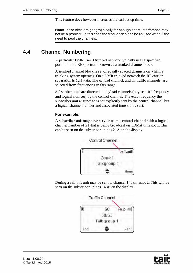
For example:
A subscriber unit may have service from a control channel with a logical channel number of 21 that is being broadcast on TDMA timeslot 1. This can be seen on the subscriber unit as 21A on the display.
During a call this unit may be sent to channel 148 timeslot 2. This will be seen on the subscriber unit as 148B on the display.
Issue 1.00.04© Tait Limited 2015
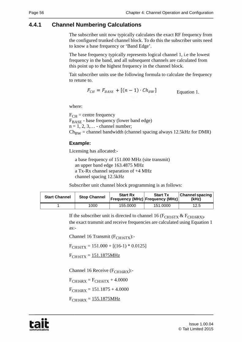
Page 56 Chapter 4: Channel Operation and Configuration
4.4.1 Channel Numbering Calculations
The subscriber unit now typically calculates the exact RF frequency from the configured trunked channel block. To do this the subscriber units need to know a base frequency or ‘Band Edge’.
The base frequency typically represents logical channel 1, i.e the lowest frequency in the band, and all subsequent channels are calculated from this point up to the highest frequency in the channel block.
Tait subscriber units use the following formula to calculate the frequency to retune to.
where:
FCH = centre frequencyFBASE - base frequency (lower band edge)n = 1, 2, 3,… - channel number;ChBW = channel bandwidth (channel spacing always 12.5kHz for DMR)
Example:
Licensing has allocated:-
a base frequency of 151.000 MHz (site transmit)an upper band edge 163.4875 MHza Tx-Rx channel separation of +4 MHzchannel spacing 12.5kHz
Subscriber unit channel block programming is as follows:
If the subscriber unit is directed to channel 16 (FCH16TX & FCH16RX), the exact transmit and receive frequencies are calculated using Equation 1 as:-
Channel 16 Transmit (FCH16TX):-
FCH16TX = 151.000 + [(16-1) * 0.0125]
FCH16TX = 151.1875MHz
Channel 16 Receive (FCH16RX):-
FCH16RX = FCH16TX + 4.0000
FCH16RX = 151.1875 + 4.0000
FCH16RX = 155.1875MHz
Equation 1.
Start Channel Stop Channel Start Rx Frequency (MHz)
Start Tx Frequency (MHz)
Channel spacing (kHz)
1 1000 155.0000 151.0000 12.5
Issue 1.00.04
© Tait Limited 2015
5.1 Learning Outcomes Page 57
Chapter 5Call Types
5.1 Learning Outcomes
Upon completion of this chapter, you will be able to do the following:
• List the different DMR call types
• Describe a talkgroup conference call
• Describe a broadcast group call
• Describe an individual (private) call
• Describe a status message call
• Describe an SDM call
• Describe an packet data call
• Describe a gateway call
Issue 1.00.04© Tait Limited 2015
Page 58 Chapter 5: Call Types
5.2 DMR Call Type Overview
Trunked radio systems enable radio users to make a wide variety of different call types, including:
Voice Calls:• talkgroup
• individual (private)
• telephone and gateway
A trunked mobile radio network provides an unrivaled and very efficient means of communication through the use of group calls.
Private calls extend the features of the radio network to provide a complete solution for all of an organizations communications needs.
Data Calls:• Status
• Short data messages (text)
• Packet data (confirmed/unconfirmed)
The technology that enables the various call types is provided by the user’s radio in some cases and by the DMR network in others. The network manager can control which call types any particular radio is allowed to make.
5.3 Voice Calls - Talkgroup
A group or talkgroup is an assigned group identity on a trunked radio system. When called, the system dynamically assigns frequencies to the group. There can be single or multiple sites involved in call.
Group calls are either
• conference
• broadcast
and may be programmed on the subscriber unit as either permanent groups, selectable/subscribed groups and/or scan groups.
Issue 1.00.04
© Tait Limited 2015
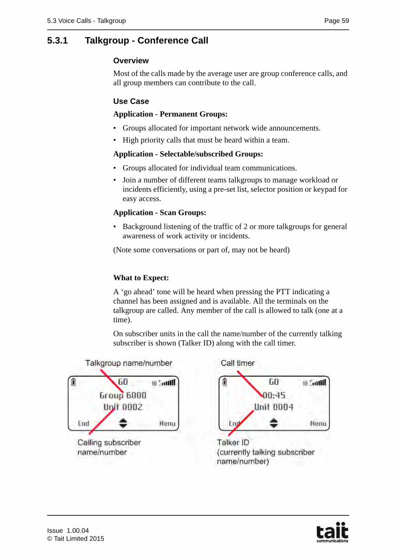
5.3 Voice Calls - Talkgroup Page 59
5.3.1 Talkgroup - Conference Call
Overview
Most of the calls made by the average user are group conference calls, and all group members can contribute to the call.
Use Case
Application - Permanent Groups:
• Groups allocated for important network wide announcements.
• High priority calls that must be heard within a team.
Application - Selectable/subscribed Groups:
• Groups allocated for individual team communications.
• Join a number of different teams talkgroups to manage workload or incidents efficiently, using a pre-set list, selector position or keypad for easy access.
Application - Scan Groups:
• Background listening of the traffic of 2 or more talkgroups for general awareness of work activity or incidents.
(Note some conversations or part of, may not be heard)
What to Expect:
A ‘go ahead’ tone will be heard when pressing the PTT indicating a channel has been assigned and is available. All the terminals on the talkgroup are called. Any member of the call is allowed to talk (one at a time).
On subscriber units in the call the name/number of the currently talking subscriber is shown (Talker ID) along with the call timer.
Issue 1.00.04© Tait Limited 2015
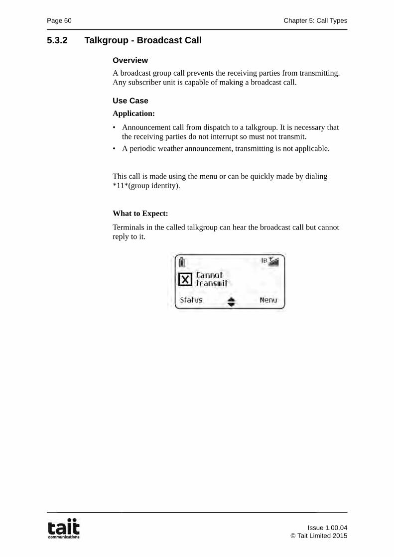
Page 60 Chapter 5: Call Types
5.3.2 Talkgroup - Broadcast Call
Overview
A broadcast group call prevents the receiving parties from transmitting. Any subscriber unit is capable of making a broadcast call.
Use Case
Application:
• Announcement call from dispatch to a talkgroup. It is necessary that the receiving parties do not interrupt so must not transmit.
• A periodic weather announcement, transmitting is not applicable.
This call is made using the menu or can be quickly made by dialing *11*(group identity).
What to Expect:
Terminals in the called talkgroup can hear the broadcast call but cannot reply to it.
Issue 1.00.04
© Tait Limited 2015
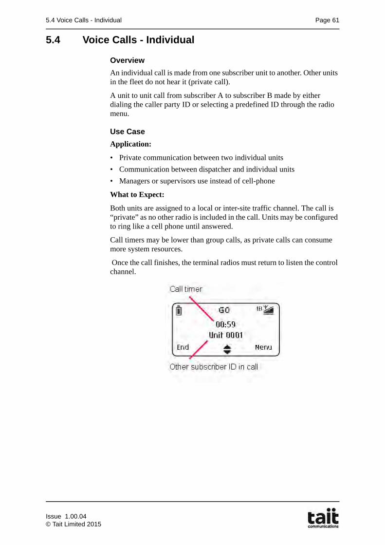
5.4 Voice Calls - Individual Page 61
5.4 Voice Calls - Individual
Overview
An individual call is made from one subscriber unit to another. Other units in the fleet do not hear it (private call).
A unit to unit call from subscriber A to subscriber B made by either dialing the caller party ID or selecting a predefined ID through the radio menu.
Use Case
Application:
• Private communication between two individual units
• Communication between dispatcher and individual units
• Managers or supervisors use instead of cell-phone
What to Expect:
Both units are assigned to a local or inter-site traffic channel. The call is “private” as no other radio is included in the call. Units may be configured to ring like a cell phone until answered.
Call timers may be lower than group calls, as private calls can consume more system resources.
Once the call finishes, the terminal radios must return to listen the control channel.
Issue 1.00.04© Tait Limited 2015
Page 62 Chapter 5: Call Types
5.5 Data Calls
A trunked mobile radio network provides one the most convenient and efficient means of communication available.
A data message can convey the same amount of information as a voice message, but data messages are transmitted by the system in a small fraction of the time. A data message provides a clear statement of requirements and is less likely to be misinterpreted than a spoken message.
Data calls can be made using the:-
• control channel for status messages and short data messages.
• traffic channel for packet data and GPS position reporting.
5.5.1 Control Channel Data - Status Message
Status messages are sent only as a numeric value on the control channel and are matched to a pre-programed look-up table label on the receiving subscriber unit.
Status messages consist of a single request with acknowledgement for individual calls. Groups Status messages are supported.
• 1 - 30 (MPT networks)
• 1 - 125 (DMR or dual mode networks)
Optionally status: 0 dispatch callback request
126 Status poll
127 dispatch callback cancel
Note: Group Status message are not Acknowledged
Note: Optional status: Implementation of these status will depend on the manufacture and the DMR revision that was used in the product development. This may result in different suppliers being incompatible with other vendors. DMR revision 1.4 has no preassigned Status, while revision 1.6 assigns 127 as the Status poll.
Issue 1.00.04
© Tait Limited 2015
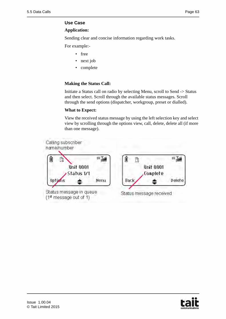
5.5 Data Calls Page 63
Use Case
Application:
Sending clear and concise information regarding work tasks.
For example:-
• free
• next job
• complete
Making the Status Call:
Initiate a Status call on radio by selecting Menu, scroll to Send -> Status and then select. Scroll through the available status messages. Scroll through the send options (dispatcher, workgroup, preset or dialled).
What to Expect:
View the received status message by using the left selection key and select view by scrolling through the options view, call, delete, delete all (if more than one message).
Issue 1.00.04© Tait Limited 2015
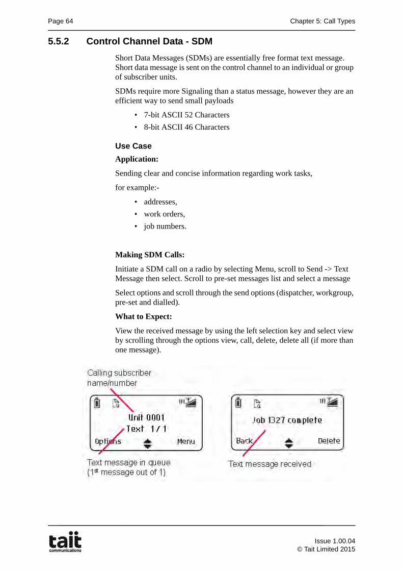
Page 64 Chapter 5: Call Types
5.5.2 Control Channel Data - SDM
Short Data Messages (SDMs) are essentially free format text message. Short data message is sent on the control channel to an individual or group of subscriber units.
SDMs require more Signaling than a status message, however they are an efficient way to send small payloads
• 7-bit ASCII 52 Characters
• 8-bit ASCII 46 Characters
Use Case
Application:
Sending clear and concise information regarding work tasks,
for example:-
• addresses,
• work orders,
• job numbers.
Making SDM Calls:
Initiate a SDM call on a radio by selecting Menu, scroll to Send -> Text Message then select. Scroll to pre-set messages list and select a message
Select options and scroll through the send options (dispatcher, workgroup, pre-set and dialled).
What to Expect:
View the received message by using the left selection key and select view by scrolling through the options view, call, delete, delete all (if more than one message).
Issue 1.00.04
© Tait Limited 2015
5.5 Data Calls Page 65
5.5.3 Traffic Channel Data - Packet Data Call
Unconfirmed Packet Data
Unconfirmed packet data is sent on a traffic channel, which requires messaging to establish a data call in the same way that voice calls are set up. The extra call setup and clear down signaling usually means that packet data is more suited to large payloads, or “chatty” application protocols.
Once a data call is established on a traffic channel, it is up to the applications to manage when data packets are sent and to avoid collisions.
Up to 1500 octets can be sent in a single packet. Each packet is transmitted in blocks over the air.
For unconfirmed data acknowledgement sent by end devices only indicate it was transmitted and does not guarantee that it was received without error. It is up to the application to manage retries etc.
Confirmed Packet Data
Confirmed packet data is similar to unconfirmed packet data, with the addition of over-the-air acknowledgements for each block. The receiving end (subscriber unit or node controller) can request that individual blocks are resent if it is detected that they were received with too many errors that could not be corrected.
Issue 1.00.04© Tait Limited 2015
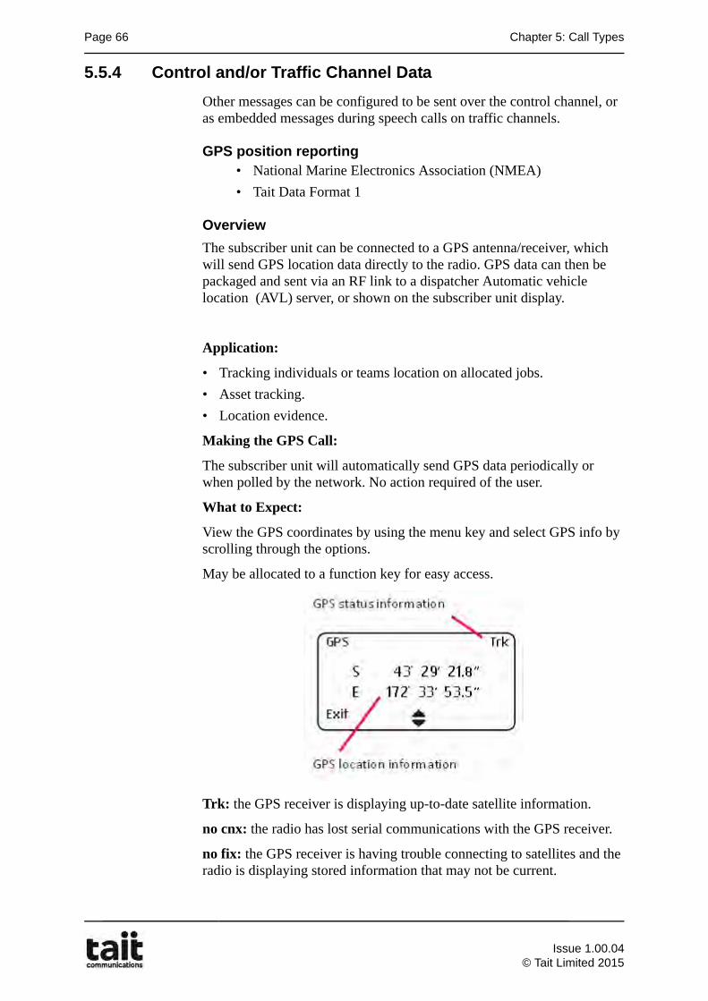
Page 66 Chapter 5: Call Types
5.5.4 Control and/or Traffic Channel Data
Other messages can be configured to be sent over the control channel, or as embedded messages during speech calls on traffic channels.
GPS position reporting• National Marine Electronics Association (NMEA)
• Tait Data Format 1
Overview
The subscriber unit can be connected to a GPS antenna/receiver, which will send GPS location data directly to the radio. GPS data can then be packaged and sent via an RF link to a dispatcher Automatic vehicle location (AVL) server, or shown on the subscriber unit display.
Application:
• Tracking individuals or teams location on allocated jobs.
• Asset tracking.
• Location evidence.
Making the GPS Call:
The subscriber unit will automatically send GPS data periodically or when polled by the network. No action required of the user.
What to Expect:
View the GPS coordinates by using the menu key and select GPS info by scrolling through the options.
May be allocated to a function key for easy access.
Trk: the GPS receiver is displaying up-to-date satellite information.
no cnx: the radio has lost serial communications with the GPS receiver.
no fix: the GPS receiver is having trouble connecting to satellites and the radio is displaying stored information that may not be current.
Issue 1.00.04
© Tait Limited 2015
5.5 Data Calls Page 67
Additional information
Tait subscriber units support GPS (Global Positioning System) and AVL (Automatic Vehicle Location) features. Portable radios have an in-built GPS antenna. Mobile radios require a standalone GPS receiver to be attached to a serial port. Features include displaying the radio’s location reported by GPS, and GPS reporting (polling and unsolicited GPS reporting)
For DMR networks, GPS data is sent using UDT (Unified Data Transport) as described in the DMR standards. The following GPS formats are supported in Tait subscriber units.
NMEA
Unsolicited GPS reports are sent using a UDT format of 0101(NMEA location coded as per the IEC 61162-1/NMEA 0183 standard).
Tait Data Format 1
Unsolicited GPS reports are sent using a UDT format of 1001 (custom coded -manufacturer specific). This format will also additional data such as the last sent status value, and the state of programmable lines set to User Status Input. This proprietary format is used for specific solutions, and should only be selected if the GPS system and DMR network supports it.
Issue 1.00.04© Tait Limited 2015
Page 68 Chapter 5: Call Types
5.6 Gateway Calls
Telephone Calls (PSTN/PABX)
Telephone connections to the DMR network require an appropriate gateway device that enables radio users to make calls to telephone users.
The network can be configured to control the level of radio subscriber access to the telephone system, and can also allow telephone subscribers to make calls to radio users. Inbound telephone calls to the DMR network can be individual or group.
Tait trunked networks can be an integral part of an organization’s telecommunications network. Connections can be made directly to telephone numbers via the PSTN or switched through the organizations PBX. Radio users and telephone users with a PABX extension number can then communicate directly.
Conventional Radio Network Calls
Connections to legacy conventional networks is possible through an appropriate gateway device. This allows cross patching of differing technologies as well as differing/same frequency bands.
Application Interface Standard (AIS)
The DMR AIS is a SIP based interconnection for DMR Tier II and Tier III radio network voice and data communications. It is suitable for dispatch consoles, voice recording, data applications such as text and LIP location, and interconnection between DMR and other radio networks.
The dispatch interface capabilities include:
An all-digital IP interface (AIS), based on the widely-used SIP (Session Initiation Protocol) but adds dispatch-specific enhancements or 'extensions' for setting up, modifying and ending dispatch calls. The voice is transmitted using a Real-Time Transport Protocol (RTP) using either the AMBE+2 vocoded voice or G.711 coded voice.
• AMBE+2, the speech encoding scheme used for DMR. When this voice stream is used, no network gateways are required.
• G.711 voice stream, an ITU-T standard for audio pulse code modulation. This will require the use of network gateways to convert between AMBE+ and G.711 formats.
Issue 1.00.04
© Tait Limited 2015
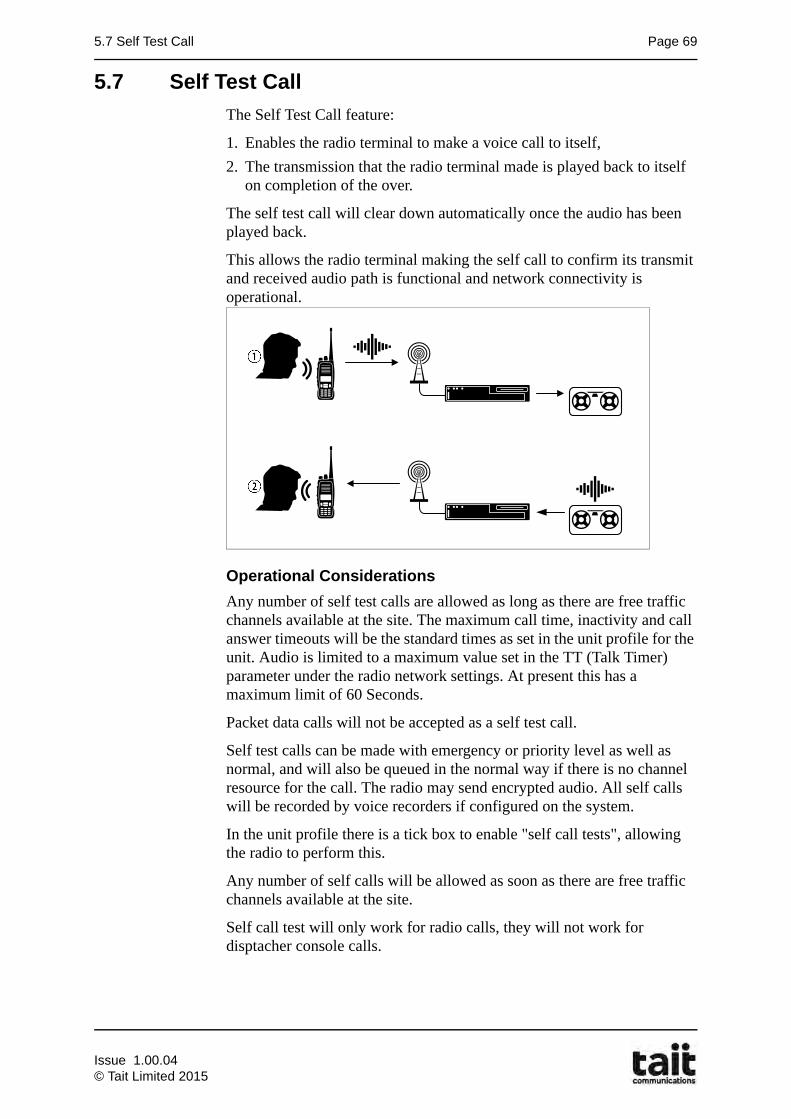
5.7 Self Test Call Page 69
5.7 Self Test Call
The Self Test Call feature:
1. Enables the radio terminal to make a voice call to itself,
2. The transmission that the radio terminal made is played back to itself on completion of the over.
The self test call will clear down automatically once the audio has been played back.
This allows the radio terminal making the self call to confirm its transmit and received audio path is functional and network connectivity is operational.
Operational Considerations
Any number of self test calls are allowed as long as there are free traffic channels available at the site. The maximum call time, inactivity and call answer timeouts will be the standard times as set in the unit profile for the unit. Audio is limited to a maximum value set in the TT (Talk Timer) parameter under the radio network settings. At present this has a maximum limit of 60 Seconds.
Packet data calls will not be accepted as a self test call.
Self test calls can be made with emergency or priority level as well as normal, and will also be queued in the normal way if there is no channel resource for the call. The radio may send encrypted audio. All self calls will be recorded by voice recorders if configured on the system.
In the unit profile there is a tick box to enable "self call tests", allowing the radio to perform this.
Any number of self calls will be allowed as soon as there are free traffic channels available at the site.
Self call test will only work for radio calls, they will not work for disptacher console calls.
Issue 1.00.04© Tait Limited 2015

Page 70 Chapter 5: Call Types
Issue 1.00.04
© Tait Limited 2015
6.1 Learning Outcomes Page 71
Chapter 6Call Features
6.1 Learning Outcomes
Upon completion of this chapter, you will be able to do the following:
• Compare DMR Call Handling Strategies
• Define DMR Call Timers
• Describe DMR Emergency and Priority Calls
• Describe DMR Network Optimization Strategies
• Describe Subscriber Unit Call Features
Issue 1.00.04© Tait Limited 2015

Page 72 Chapter 6: Call Features
6.2 DMR Call Handling Strategies
Call processing on the TaitNet System is fully automatic. Generally, whenever a user wishes to place a call on the system, he, or she, simply selects from a list, or enters the ID number of the unit or group to call, and presses the push to talk button (PTT). Each unit or talkgroup may be called in the same manner, no matter where it is located on the system.
The following features apply to individual and/or group calls as indicated, on TaitNet DMR networks.
6.2.1 Transmission Trunked
Used only for group calls. When a call is made, the call proceeds to a traffic channel. The calling radio proceeds to talk. On releasing the PTT the radio sends a call clear down message and returns to the control channel. The traffic channel is free to other users. If the system is busy then a reply to the previous transmission may be queued until a channel is free. This operation is similar to Logic Trunked Radio (LTR) system that E.F. Johnson deployed.
6.2.2 Message Trunked
Used for group calls and individual calls. When a call is made, the call proceeds to a traffic channel and a call time limit is started. The caller and called parties proceed to talk for that period of time. The call is ended by either:
• the network call time period expiring.
• the users pressing an end call (clear) button.
• the idle period time expires.
This operation is similar to MPT networks.
The trade off between transmission and message trunking is call setup speed versus channel reuse efficiency
Issue 1.00.04
© Tait Limited 2015
6.2 DMR Call Handling Strategies Page 73
6.2.3 Individual Call Setup Handling Strategy
Full Off Air Call Setup (FOACSU)
Trunking systems can set up calls in two ways. In some systems, it is possible for the system to seek acknowledgement from the called party before setting up a call. This can improve channel efficiency, and provides a fast response to PSTN inward calling. The Radio Unit must also be configured to support the operation.
A unit to unit call with FOACSU behaves like a cellular phone, the called radio will ring and the user must PTT to answer.
Allowed: (Feature enabled) A subscriber to subscriber call with FOACSU behaves like a cellular phone, the called radio will ring and the user must PTT to answer. Acknowledgement will be sought from the called party before a traffic channel will be allocated for the call. However, if the system is not capable of seeking acknowledgement, setting FOACSU to Allowed will have no effect.
Disallowed: (Feature disabled) A traffic channel will be allocated for the call before the called radio has answered, therefore the call goes to channel straight away and called party can hear the caller. This is sometimes called off air call setup (OACSU)
6.2.4 Group Call Setup Handling Strategy
Late Entry to Group Calls (Repeat Go-To-Channel Messaging)
Late entry enables radios to join a group call after it has started. The control channel sends GTC messages at intervals, inviting radios in the group to join the call. Radios that are busy in another call, out of range, or turned off will miss the group call. Late entry makes it possible for them to join in later.
The late entry feature is enabled (or disabled) individually for each group on the system. This means that within a system, some groups can be late entry groups, while other groups are not.
Issue 1.00.04© Tait Limited 2015
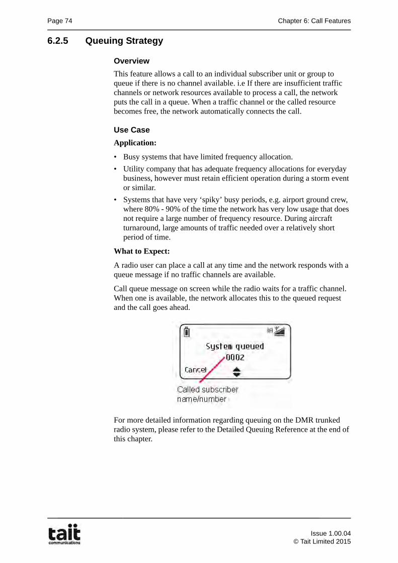
Page 74 Chapter 6: Call Features
6.2.5 Queuing Strategy
Overview
This feature allows a call to an individual subscriber unit or group to queue if there is no channel available. i.e If there are insufficient traffic channels or network resources available to process a call, the network puts the call in a queue. When a traffic channel or the called resource becomes free, the network automatically connects the call.
Use Case
Application:
• Busy systems that have limited frequency allocation.
• Utility company that has adequate frequency allocations for everyday business, however must retain efficient operation during a storm event or similar.
• Systems that have very ‘spiky’ busy periods, e.g. airport ground crew, where 80% - 90% of the time the network has very low usage that does not require a large number of frequency resource. During aircraft turnaround, large amounts of traffic needed over a relatively short period of time.
What to Expect:
A radio user can place a call at any time and the network responds with a queue message if no traffic channels are available.
Call queue message on screen while the radio waits for a traffic channel. When one is available, the network allocates this to the queued request and the call goes ahead.
For more detailed information regarding queuing on the DMR trunked radio system, please refer to the Detailed Queuing Reference at the end of this chapter.
Issue 1.00.04
© Tait Limited 2015
6.3 DMR Call Timers Page 75
6.3 DMR Call Timers
The network times various stages of a call, and will clear down the call if the radio is not using the channel efficiently or defined limits have been reached.
6.3.1 Call Time Limits
The Call Time Limits area configures timers that limit the length of different types of call. When a timer expires, the node clears down the call.
Note: If a timer is set to 0 seconds, there is a limit to the length of the call to 900 seconds [15 minutes] (however, an inactivity time-out can end the call if no voice or data is sent).
Voice
Defines the call time limit for radio-to-radio normal and priority speech calls.
Emergency voice
Defines the call time limit for radio-to-radio emergency speech calls.
Phone
Defines the call time limit for radio-to-telephone and telephone-to-radio normal and priority calls.
Emergency phone
Defines the call time limit for emergency calls to or from a telephone.
6.3.2 Other Timers
Call Inactivity Time-outs
Call inactivity time-outs define how long there can be silence in a call before the node clears the call down. Once a call is in progress, the node restarts a timer, each time the carrier signal on the traffic channel ceases. If a radio doesn’t transmit and the timer expires and the node clears the call down. Different call inactivity timers are available for the different call types as described above.
Benefit:- This allows for this 'inactive' channel to be quickly returned to the available pool of resources so that it can be allocated to a new call.
Example:- A truck driver just puts the microphone down at the end of a conversation instead of pressing the disconnect key. The channel will be available for reuse sooner than the call limit timeout may provide.
Note: It is possible to disable inactivity time-outs for emergency calls, by entering a value of 0.
Issue 1.00.04© Tait Limited 2015
Page 76 Chapter 6: Call Features
Call Answer Time-outs
Call answer time-outs define how long the node waits for a call to be answered, before clearing the call down. Different call answer timers are available for the different call types
• Voice
• Phone
• Emergency voice
• Emergency phone
GTC Repeat Interval
This parameter defines the frequency with which repeated GTC (Go to Channel) messages are sent on the control channel during group calls. It also defines the frequency with which repeat transmit inhibit messages are sent on the traffic channel during broadcast calls.
The GTC Repeat Interval parameter is not used with groups that do not have late entry enabled.The smaller the value chosen for this parameter, the more difficult it is for radios to leave a group call and call anyone else.
Ignore Received Channel Grant Time
The subscriber unit configuration has timer that works in parallel with the control channel GTC repeat interval called “Ignore Received Channel Grant Time”.
This feature is used when receiving an unwanted group call. If this field is set to 0 and the radio user clears down the call (for example, to make another call), the radio will re-enter the group call as soon as the next GTC command is received. That may happen before the radio user has had a chance to dial the new call.
If a time is entered and that time is still counting down, repeated request for GTC to re-enter the group call will be ignored.
Issue 1.00.04
© Tait Limited 2015
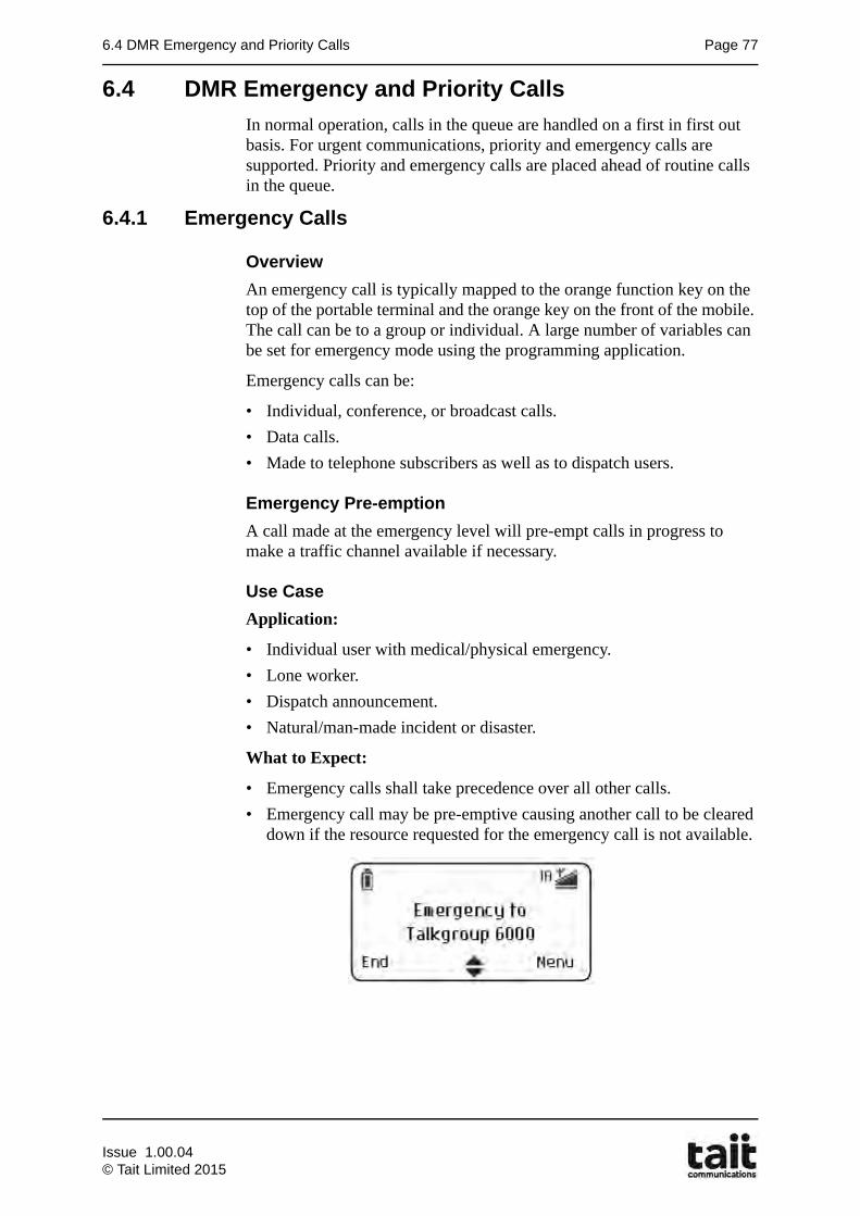
6.4 DMR Emergency and Priority Calls Page 77
6.4 DMR Emergency and Priority Calls
In normal operation, calls in the queue are handled on a first in first out basis. For urgent communications, priority and emergency calls are supported. Priority and emergency calls are placed ahead of routine calls in the queue.
6.4.1 Emergency Calls
Overview
An emergency call is typically mapped to the orange function key on the top of the portable terminal and the orange key on the front of the mobile. The call can be to a group or individual. A large number of variables can be set for emergency mode using the programming application.
Emergency calls can be:
• Individual, conference, or broadcast calls.
• Data calls.
• Made to telephone subscribers as well as to dispatch users.
Emergency Pre-emption
A call made at the emergency level will pre-empt calls in progress to make a traffic channel available if necessary.
Use Case
Application:
• Individual user with medical/physical emergency.
• Lone worker.
• Dispatch announcement.
• Natural/man-made incident or disaster.
What to Expect:
• Emergency calls shall take precedence over all other calls.
• Emergency call may be pre-emptive causing another call to be cleared down if the resource requested for the emergency call is not available.
Issue 1.00.04© Tait Limited 2015
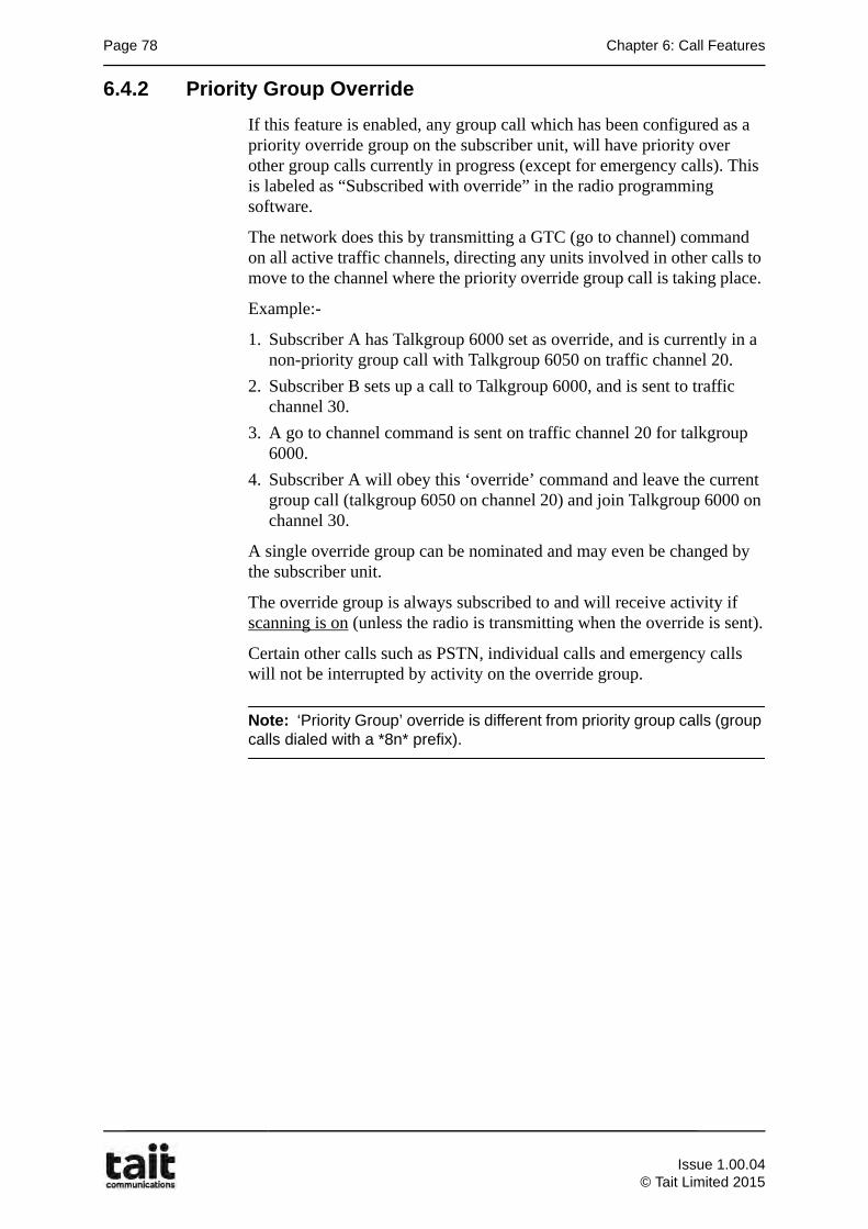
Page 78 Chapter 6: Call Features
6.4.2 Priority Group Override
If this feature is enabled, any group call which has been configured as a priority override group on the subscriber unit, will have priority over other group calls currently in progress (except for emergency calls). This is labeled as “Subscribed with override” in the radio programming software.
The network does this by transmitting a GTC (go to channel) command on all active traffic channels, directing any units involved in other calls to move to the channel where the priority override group call is taking place.
Example:-
1. Subscriber A has Talkgroup 6000 set as override, and is currently in a non-priority group call with Talkgroup 6050 on traffic channel 20.
2. Subscriber B sets up a call to Talkgroup 6000, and is sent to traffic channel 30.
3. A go to channel command is sent on traffic channel 20 for talkgroup 6000.
4. Subscriber A will obey this ‘override’ command and leave the current group call (talkgroup 6050 on channel 20) and join Talkgroup 6000 on channel 30.
A single override group can be nominated and may even be changed by the subscriber unit.
The override group is always subscribed to and will receive activity if scanning is on (unless the radio is transmitting when the override is sent).
Certain other calls such as PSTN, individual calls and emergency calls will not be interrupted by activity on the override group.
Note: ‘Priority Group’ override is different from priority group calls (group calls dialed with a *8n* prefix).
Issue 1.00.04
© Tait Limited 2015
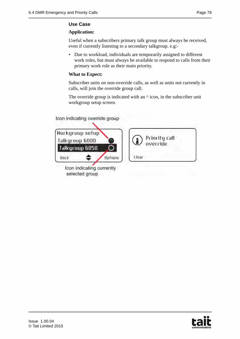
6.4 DMR Emergency and Priority Calls Page 79
Use Case
Application:
Useful when a subscribers primary talk group must always be received, even if currently listening to a secondary talkgroup. e.g:-
• Due to workload, individuals are temporarily assigned to different work roles, but must always be available to respond to calls from their primary work role as their main priority.
What to Expect:
Subscriber units on non-override calls, as well as units not currently in calls, will join the override group call.
The override group is indicated with an ^ icon, in the subscriber unit workgroup setup screen.
Issue 1.00.04© Tait Limited 2015
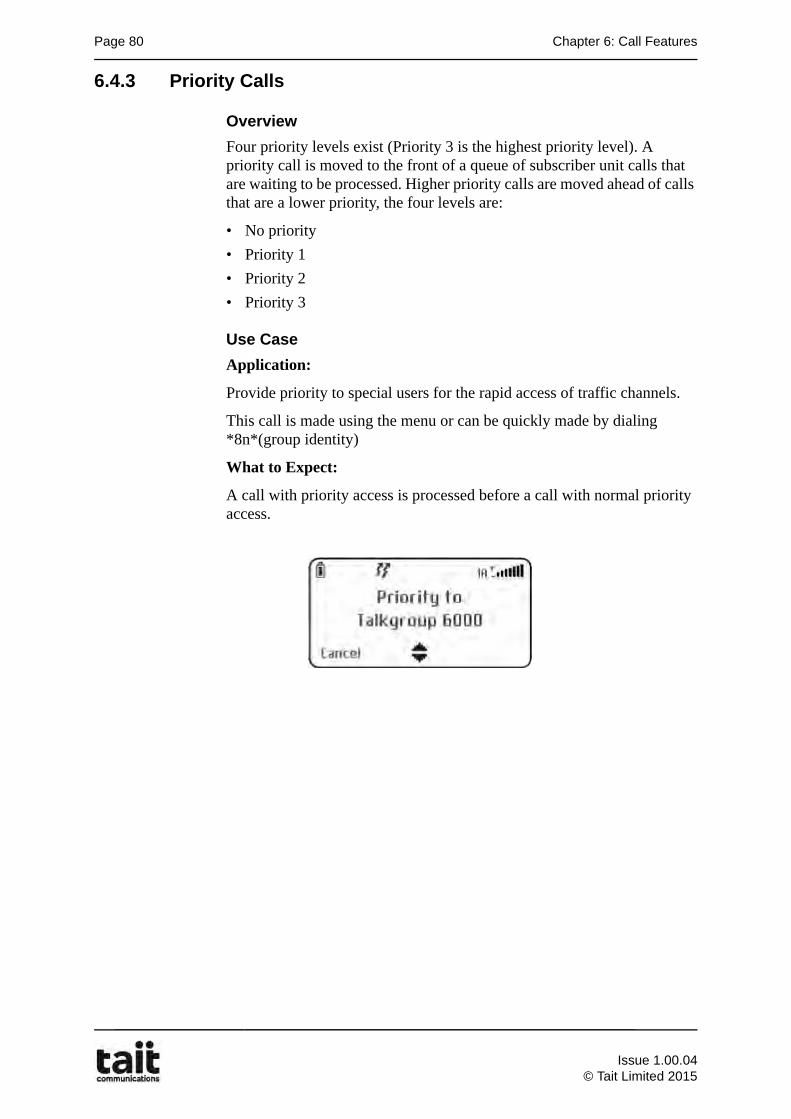
Page 80 Chapter 6: Call Features
6.4.3 Priority Calls
Overview
Four priority levels exist (Priority 3 is the highest priority level). A priority call is moved to the front of a queue of subscriber unit calls that are waiting to be processed. Higher priority calls are moved ahead of calls that are a lower priority, the four levels are:
• No priority
• Priority 1
• Priority 2
• Priority 3
Use Case
Application:
Provide priority to special users for the rapid access of traffic channels.
This call is made using the menu or can be quickly made by dialing *8n*(group identity)
What to Expect:
A call with priority access is processed before a call with normal priority access.
Issue 1.00.04
© Tait Limited 2015
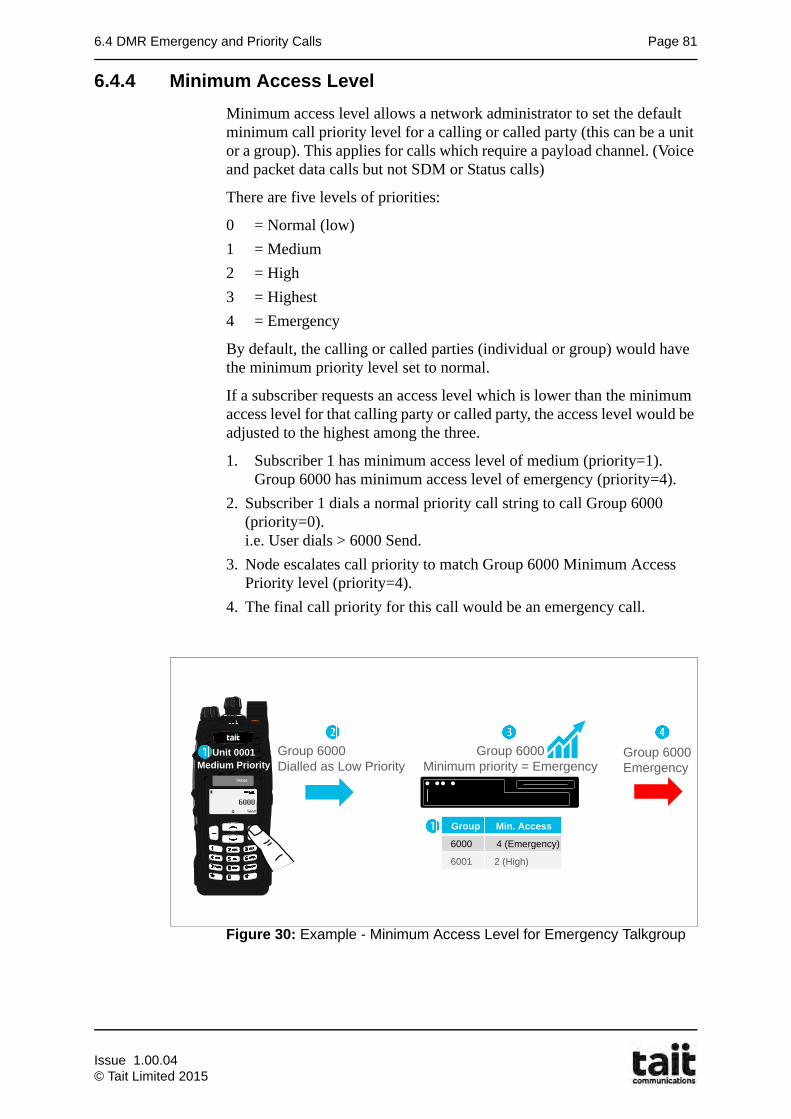
6.4 DMR Emergency and Priority Calls Page 81
6.4.4 Minimum Access Level
Minimum access level allows a network administrator to set the default minimum call priority level for a calling or called party (this can be a unit or a group). This applies for calls which require a payload channel. (Voice and packet data calls but not SDM or Status calls)
There are five levels of priorities:
0 = Normal (low)
1 = Medium
2 = High
3 = Highest
4 = Emergency
By default, the calling or called parties (individual or group) would have the minimum priority level set to normal.
If a subscriber requests an access level which is lower than the minimum access level for that calling party or called party, the access level would be adjusted to the highest among the three.
1. Subscriber 1 has minimum access level of medium (priority=1).Group 6000 has minimum access level of emergency (priority=4).
2. Subscriber 1 dials a normal priority call string to call Group 6000 (priority=0).i.e. User dials > 6000 Send.
3. Node escalates call priority to match Group 6000 Minimum Access Priority level (priority=4).
4. The final call priority for this call would be an emergency call.
Figure 30: Example - Minimum Access Level for Emergency Talkgroup
Group Min. Access
6000 4 (Emergency)
6001 2 (High)
Group 6000Dialled as Low Priority
Group 6000 Minimum priority = Emergency
Group 6000 Emergency
Group Min. Access
6000 4 (Emergency)
6001 2 (High)
6000Send
TP9300
Unit 0001 Medium Priority
Issue 1.00.04© Tait Limited 2015

Page 82 Chapter 6: Call Features
6.4.5 Configuration
In the node web UI, the unit and group profile now includes two new parameters under a new heading of 'Default Minimum Priority':
• voice calls
• ip / packet data
There is a drop down menu for each parameter allowing a priority level of: normal (low), medium, high, highest, or emergency to be set. This corresponds to how priority levels are now defined in the DMR trunking specification.
By default all unit and group profiles will set these parameters as normal, i.e. the lowest value.
6.4.6 Operational Considerations
High Priority Call Request
If a subscriber requests an access level which is higher than the minimum access level for that calling party or called party, the access level would NOT be adjusted. The node does not adjust down the call priority level.
Calling Party Access Validation
When a call access level is adjusted, the node would not validate the access level setting of the calling party.
This means, when a radio is restricted to make only normal call, if its profile or the called party's profile has minimum access level set to emergency, then the call would be made as an emergency call. Call record display only the final call priority level.
This allows for a unit that is not allowed to make emergency priority calls, for example, but is still able to call a group which has a minimum call priority that is emergency.
Call Records
Call records indicate the final call priority, not the initial call priority. There is no indication in the call record that the priority has changed. The node log records if the call priority has been adjusted.
Issue 1.00.04
© Tait Limited 2015
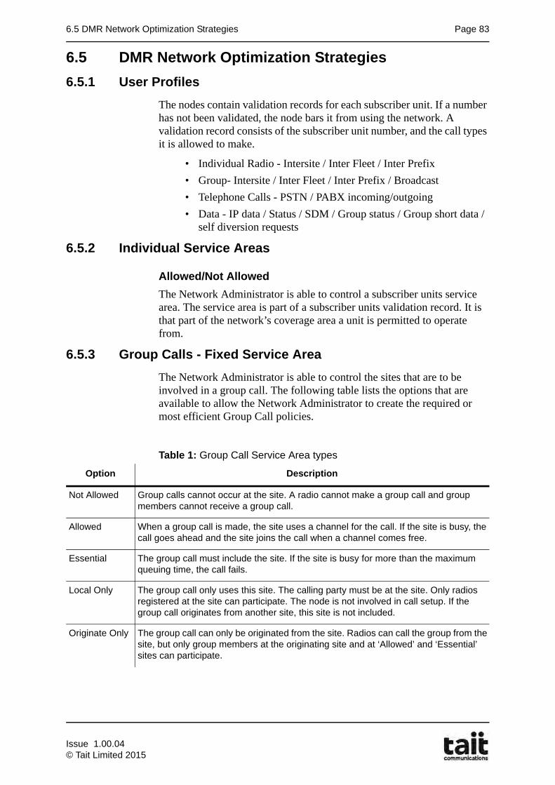
6.5 DMR Network Optimization Strategies Page 83
6.5 DMR Network Optimization Strategies
6.5.1 User Profiles
The nodes contain validation records for each subscriber unit. If a number has not been validated, the node bars it from using the network. A validation record consists of the subscriber unit number, and the call types it is allowed to make.
• Individual Radio - Intersite / Inter Fleet / Inter Prefix
• Group- Intersite / Inter Fleet / Inter Prefix / Broadcast
• Telephone Calls - PSTN / PABX incoming/outgoing
• Data - IP data / Status / SDM / Group status / Group short data / self diversion requests
6.5.2 Individual Service Areas
Allowed/Not Allowed
The Network Administrator is able to control a subscriber units service area. The service area is part of a subscriber units validation record. It is that part of the network’s coverage area a unit is permitted to operate from.
6.5.3 Group Calls - Fixed Service Area
The Network Administrator is able to control the sites that are to be involved in a group call. The following table lists the options that are available to allow the Network Administrator to create the required or most efficient Group Call policies.
Table 1: Group Call Service Area types
Option Description
Not Allowed Group calls cannot occur at the site. A radio cannot make a group call and group members cannot receive a group call.
Allowed When a group call is made, the site uses a channel for the call. If the site is busy, the call goes ahead and the site joins the call when a channel comes free.
Essential The group call must include the site. If the site is busy for more than the maximum queuing time, the call fails.
Local Only The group call only uses this site. The calling party must be at the site. Only radios registered at the site can participate. The node is not involved in call setup. If the group call originates from another site, this site is not included.
Originate Only The group call can only be originated from the site. Radios can call the group from the site, but only group members at the originating site and at ‘Allowed’ and ‘Essential’ sites can participate.
Issue 1.00.04© Tait Limited 2015

Page 84 Chapter 6: Call Features
The key shown below is used for the following series of illustrations.
Allowed
When a group call is made, the site uses a channel for the call. If the far site is busy, the call is queued and is then setup when a channel becomes free at the far site or the maximum queuing time expires, The far site is included once a channel is free.
Figure 31: Illustration of “Allowed” fixed service area group call type
Key
Site part of call service area
Subscriber originating call
Subscriber(s) receiving call
Call unsuccesful
Site busy
Dedicated Data LinkTCP / IP
Site 2
Control / Switching Node
Site 3
Site 1 Site 2
Allowed
Allowed
Dedicated Data LinkTCP / IP
Allowed
Issue 1.00.04
© Tait Limited 2015
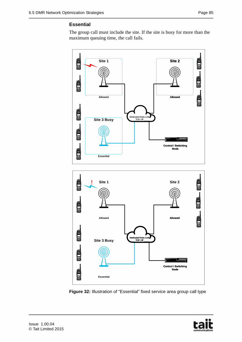
6.5 DMR Network Optimization Strategies Page 85
Essential
The group call must include the site. If the site is busy for more than the maximum queuing time, the call fails.
Figure 32: Illustration of “Essential” fixed service area group call type
Dedicated Data LinkTCP / IP
Control / Switching Node
Site 3 Busy
Site 1 Site 2
Allowed
Dedicated Data LinkTCP / IP
Allowed
Essential
Allowed
Site 2
Control / Switching Node
Dedicated Data LinkTCP / IP
Control / Switching Node
Site 3 Busy
Site 1 Site 2
Essential
Allowed
Dedicated Data LinkTCP / IP
Control / Switching Node
Allowed Allowed
Dedicated Data LinkTCP / IP
Issue 1.00.04© Tait Limited 2015
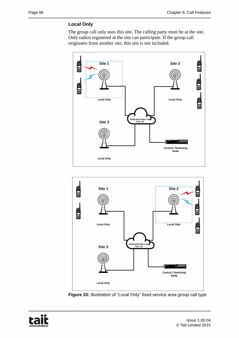
Page 86 Chapter 6: Call Features
Local Only
The group call only uses this site. The calling party must be at the site. Only radios registered at the site can participate. If the group call originates from another site, this site is not included.
Figure 33: Illustration of “Local Only” fixed service area group call type
Dedicated Data LinkTCP / IP
Control / Switching Node
Site 3
Site 1 Site 2
Local Only
Local Only
Dedicated Data LinkTCP / IP
Local Only
Dedicated Data LinkTCP / IP
Site 2
Control / Switching Node
Site 3
Site 1 Site 2
Local Only
Local Only
Dedicated Data LinkTCP / IP
Local Only
Issue 1.00.04
© Tait Limited 2015
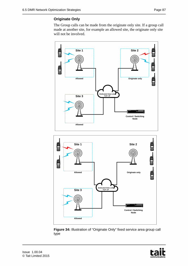
6.5 DMR Network Optimization Strategies Page 87
Originate Only
The Group calls can be made from the originate only site. If a group call made at another site, for example an allowed site, the originate only site will not be involved.
Figure 34: Illustration of “Originate Only” fixed service area group call type
Dedicated Data LinkTCP / IP
Site 2
Control / Switching Node
Site 3
Site 1 Site 2
Allowed
Originate only
Dedicated Data LinkTCP / IP
Allowed
Dedicated Data LinkTCP / IP
Control / Switching Node
Site 3
Site 1 Site 2
Allowed
Originate only
Dedicated Data LinkTCP / IP
Allowed
Issue 1.00.04© Tait Limited 2015
Page 88 Chapter 6: Call Features
6.5.4 Groups Call - Controlled Service Area
Once a group calls fixed service area has been defined, the network administrator can further improve the efficiency of the group call by enabling a group call feature that only uses sites that currently have talkgroup members located, and who are actually ‘signed-on’ to receive the talkgroup traffic.
Group Affiliation
Group affiliation allows a subscriber unit to update their group affiliation over the air. It is implemented by having a unit ‘sign on’ to a group to indicate that it should now be included as a member of the group’s tracked units.
When a call request is made to the talkgroup, the call will be set up at only those sites where at least one signed-on subscriber unit member of the group’s tracked units had its last registration recorded.
This ensures that traffic channels are only established on sites where radios are going to participate in that call and so improves network channel efficiency.
Tait radio controlled group affiliation (RCGA)
This feature is supported by Tait subscriber units. This allows the unit to join or leave groups by sending a short data message. It is also possible to manually regroup subscriber units from the node.
Issue 1.00.04
© Tait Limited 2015
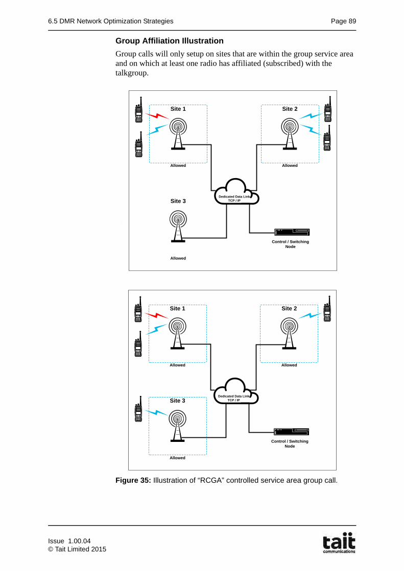
6.5 DMR Network Optimization Strategies Page 89
Group Affiliation Illustration
Group calls will only setup on sites that are within the group service area and on which at least one radio has affiliated (subscribed) with the talkgroup.
Figure 35: Illustration of “RCGA” controlled service area group call.
Dedicated Data LinkTCP / IP
Site 2
Control / Switching Node
Site 3
Site 1 Site 2
Allowed
Allowed
Dedicated Data LinkTCP / IP
Allowed
Dedicated Data LinkTCP / IP
Site 2
Control / Switching Node
Site 3
Site 1 Site 2
Allowed
Allowed
Dedicated Data LinkTCP / IP
Allowed
Issue 1.00.04© Tait Limited 2015
Page 90 Chapter 6: Call Features
6.5.5 Mobility
Diversions
Self Divert:
If allowed a Radio can Divert all of their incoming calls to a radio, dispatcher or a telephone number.
Divert on Busy:
If this feature is enabled a call made to a radio that is currently involved in a call will be diverted to a defined number, instead of being queued or failing with the reason “engaged”. The diversion does not have to be to another radio, it can be to any valid unit in the system, for example, a line dispatcher or a phone.
Divert on Not Home:
If this feature is enabled, a call made to a radio that is switched off or out of contact will be diverted to a defined number. The diversion does not have to be to another radio, it can be to any valid unit in the system, for example, a line dispatcher or a phone.
6.5.6 Asset Management
Access Level
There are four access levels a radio may have on a TaitNet network. The following table lists the options that are available to allow the Network Administrator to control the radio unit access to the network.
Option Description
Barred Radio is NOT able to make any calls.
Normal Radio is able to make all normal level calls.
Priority Radio is able to make priority calls (priority requires the *8* prefix to be dialled first). Priority calls jump to front of call queue.
Emergency Radio is able to make emergency calls (emergency requires the *9* prefix to be dialled first). Emergency calls jump to front of queue and pre-empt a traffic channel if required.
Issue 1.00.04
© Tait Limited 2015
6.5 DMR Network Optimization Strategies Page 91
6.5.7 Stun and Revive
The TaitNet Network Administrator can stun a Tait radio. This is useful if the radio has been stolen. A radio that is stunned cannot make or receive calls. The keyboard is locked. Its display indicates that it is stunned. The radio cannot be used, even in conventional (non-trunked) mode, but it will still register so that the NMT can tell you roughly where it is. You can recover a stunned radio, returning it to normal functioning provided that it is turned on and registered on the network.
A stunned radio will still receive (and answer) a GPS poll.
6.5.8 Authentication key
Each subscriber unit has a factory-programmed authentication key that is checked by the node to ensure that a radio registering on the network is genuine.
The serial number of a subscriber unit is entered in the Authentication key field of the node subscriber database, and an RC4 Cipher encryption algorithm is used to generate a 56-bit authentication key.
The node uses this 56-bit key to process a secure validation check of the subscriber units hardware on the network.
An authentication check is carried out as follows. The node polls a radio via the control channel of the site where the unit is currently registered, asking it to provide its authentication key. When a response is received, the node checks it against the key that is entered in the.
Authentication checks can be configured to be performed on registration and/or on call requests. The network can also be configured to reject requests that fail authentication.
Note: The authentication process is based on RC4 [Rivest Cipher 4] encryption (a popular encryption algorithm commonly used to protect Internet and wireless traffic). Radios have a 56-bit authentication key.
Issue 1.00.04© Tait Limited 2015
Page 92 Chapter 6: Call Features
6.6 Subscriber Unit Call Features
Various call features are provided by the user’s radio unit and are typically part of the radios unique configuration.
Pre-set Calls
Preset calls are simply numbers saved along with a name or alpha numeric tag that allows quick and easy access to the most common numbers dialled. The preset calls programmed for your radio may be to other radios, to PABX extensions or to PSTN numbers. To make a preset call from your radio, you may be able to either:
• use a programmed function key,
• use the selector switch,
• use the main menu, or
• dial the preset call using the keypad
Preset calls can also be used to activate or deactivate a function, temporarily subscribe your radio to a group, change to conventional channels and change to a different trunking network. Up to 100 pre-set numbers can be entered.
Caller ID
Radio displays caller number (and name if recorded in preset list).
Talker ID
Radio displays the ID of the current talker in a group call
Call Back feature
After a call has ended, there is the ability for the radio to allow quick and easy call back.
• Terminated calls: caller details are stored - pressing PTT re-establishes the call.
• Missed calls: caller details are displayed with an audio warning - call back by pressing PTT.
Call Divert• If allowed, Call Divert. (Call Forwarding) can be performed from the
radio unit.This can either be a self or third party divert. Additionally the radio can enable a Do Not Disturb or Queue incoming calls feature.
Conventional channels
A number of preset conventional channels (currently 1500) are available on the subscriber units. It is possible to change to conventional channels using the channel selector. Radios with an alphanumeric keypad may be able to dial the channel number. In conventional mode, you communicate directly with other radios or via a repeater rather than through the trunking network.
Issue 1.00.04
© Tait Limited 2015
6.7 Detailed Queuing Reference Page 93
6.7 Detailed Queuing Reference
6.7.1 Queuing Overview
A new call request at a site will be queued if one of the following occurs:
1. There are no free channels at the site to put the call on. Will be queued for busy party.
2. The called party is already in a call at that site (this can include parties that are already queued). Will be queued for busy channel.
3. There are already calls queued at the site. Will be queued for busy party.
One exception to this rule is amalgamation which will be explained later.
The queue is ordered by:
1. Emergency calls first
2. Priority calls next
3. Normal level calls last
If calls are at the same level they are based on oldest first.
The type of call does not matter (i.e. data vs voice)
The node will not allow two calls to the same party to be queued.
Whenever a channel becomes free at a site it will assign the free channel to the highest order call in the queue. In this case it will always assign an emergency call first if there is one in the queue.
The node will only allow calls to be queued for a configurable amount of time. If a call times-out in the queue it will send "system busy" or "engaged" depending on how it was queued.
There is also a finite limit on how many calls are queued at each site.
6.7.2 Qued Call Scenarios
Engaged
Individual normal and priority calls that are made to a busy party will not be queued for busy party. They will be rejected straight away for "engaged".
Emergency Pre-emption for busy Individual party
An Individual Emergency call made to a busy party will be queued. The node will attempt to pre-empt the call that the busy party is in.
Amalgamation
For a normal or priority call to a group that is already on channel, the node will amalgamate the group in to the existing call. This means it will send a channel grant to the new call straight away, and not queue the call at all.
Issue 1.00.04© Tait Limited 2015
Page 94 Chapter 6: Call Features
Emergency Pre-emption for busy group
If an emergency call is made to a group that is already on channel, the node will not amalgamate the group call. In this scenario it is important for all the users to know that the group call has now become an emergency call. This means the node has to re-establish the group call. It will:
1. Pre-empt the existing group call. All radios will be cleared back to the control channel
2. Once all channels are cleared, it will send a new channel grants for the group indicating it is an emergency call.
Emergency Pre-emption for busy channel
If a site is busy, the node will attempt to clear down calls to free up a channel. It a call does not clear down (e.g. because someone is transmitting in the call) then the node will then attempt to clear a 2nd channel. The node can potentially clear down all channels at a site.
Note: The Node will never pre-empt an existing emergency call.
Emergency pre-emption of the queue
If an emergency call is made to a party or group that is in the queue then the existing call will be cleared from the queue (unless it was an emergency call). The node does not allow busy party queueing so you should only ever have one call in the queue for a particular unit.
Site queues
Each site has an independent queue. This means a call could potentially be queued at the calling site first, and then the called sites. It will not attempt to get channel resource at the called sites until the calling site has resource.
Cross over queued calls
This is an interesting problem that can happen with queuing. If two intersite calls start at the same time, on different sites, it is possible for them to both reserve a channel at their initiating sites, but then not have a channel available at the called site, because of the other call reserving a channel. One of the calls would only setup once the other call gives up and clears down.
However if one of these calls is an emergency call, then it would setup because pre-emption would clear the other call.
Issue 1.00.04
© Tait Limited 2015
6.7 Detailed Queuing Reference Page 95
6.7.3 Channel Management for Queuing
Channel Allocation
The called party in a call is not notified of the call until there are channels available at all sites in the call. These means that a call could be queued for busy channel, and then fail because the called party is out of service.
Group call Setup times
Whenever a group sets up it will attempt to find channels at every site in the service area. However, if any of the called sites are queued because there are no channels available, the node will wait for the sites to become ready before it sets up the call.
The group can be configured so that the node will only wait a certain amount of time for this to happen - this is called the group setup time. At the end of the group setup time it will setup the call on all sites that are ready. As other channel become ready, they will be brought in to the call as well.
The group call setup timeout only comes in to effect once we start to find channels. An emergency group call may be queued first for busy party. This means the original group must totally clear down first.
Essential sites
The node can be configured so that some sites are essential to the group call. In this case, at the end of the group setup time, it will fail the call if any of the essential sites are not ready for the call.
Late Entry
When a radio is in another call, it may miss the channel grant to the group. In this case once the radio has cleared from its own call it will be pulled in to the group due to late entry. The node will send late entries for groups every 10 seconds by default.
Stuck mute timeout
When a call is clearing down the node will wait for the channel to become totally idle. This includes radios that might be transmitting at the site. There is currently no way to tell a radio to stop transmitting.
If a cleared channel takes too long to clear (>30s) then the node will mark the channel as stuck mute, and will consider the call completed anyway. Depending on configuration it may also mark the channel as jammed and not use it for further calls.
Issue 1.00.04© Tait Limited 2015
Page 96 Chapter 6: Call Features
Homegroup override
If the homegroup override feature is enabled in the node for a group, it means that when the group is set up it will attempt to pull in any radios at the site that may already be in different calls.
It does by transmitting messages on all active channels at the site. These messages are either:
• Sending a channel grant CSBK on the payload channel if no one is talking in the call
• Overriding the embedded signalling to send a Tait proprietary message on channels where there is someone talking.
Radios will only swap to the new group if this group has been configured for it.
Note: the XPA uses the term 'priority group' instead of homegroup override.
Emergency group override
This is similar to "homegroup override" but for emergency calls instead.
Clearing a call while someone is talking
If someone is talking in a call, and the node wishes to clear down the call, it can override the audio to send CLEAR messages that will clear out all the receiving radios.
However, there is currently no way to clear the talking party,as Tait terminals are half duplex.
Issue 1.00.04
© Tait Limited 2015

7.1 Learning Outcomes Page 97
Chapter 7Numbering
7.1 Learning Outcomes
Upon completion of this chapter, you will be able to do the following:
• Describe Tait numbering compatibility
• Define DMR Numbering
• Describe DMPT 1327 Addressing
• Demonstrate dialling calls in MPT1327
Issue 1.00.04© Tait Limited 2015
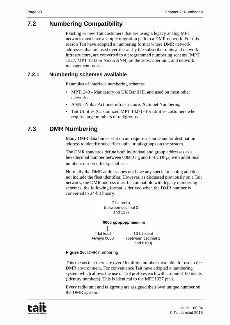
Page 98 Chapter 7: Numbering
7.2 Numbering Compatibility
Existing or new Tait customers that are using a legacy analog MPT network must have a simple migration path to a DMR network. For this reason Tait have adopted a numbering format where DMR network addresses that are used over-the-air by the subscriber units and network infrastructure, are converted to a programmed numbering scheme (MPT 1327, MPT 1343 or Nokia ANN) on the subscriber unit, and network management tools.
7.2.1 Numbering schemes available
Examples of interface numbering schemes
• MPT1343 - Mandatory on UK Band III, and used on most other networks
• ANN - Nokia Actionet infrastructure: Actionet Numbering
• Tait Utilities (Customized MPT 1327) - for utilities customers who require large numbers of talkgroups
7.3 DMR Numbering
Many DMR data bursts sent on air require a source and/or destination address to identify subscriber units or talkgroups on the system.
The DMR standards define both individual and group addresses as a hexadecimal number between 00000116 and FFFCDF16, with additional numbers reserved for special use.
Normally the DMR address does not have any special meaning and does not include the fleet identifier. However, as discussed previously on a Tait network, the DMR address must be compatible with legacy numbering schemes, the following format is derived when the DMR number is converted to 24-bit binary:
Figure 36: DMR numbering
This means that there are over 16 million numbers available for use in the DMR environment. For convenience Tait have adopted a numbering system which allows the use of 128 prefixes each with around 8100 idents (identity numbers). This is identical to the MPT1327 plan.
Every radio unit and talkgroup are assigned their own unique number on the DMR system.
0000 ppppppp iiiiiiiiiiiii
4-bit leadAlways 0000
13-bit ident(between decimal 1
and 8100)
7-bit prefix(between decimal 0
and 127)
Issue 1.00.04
© Tait Limited 2015
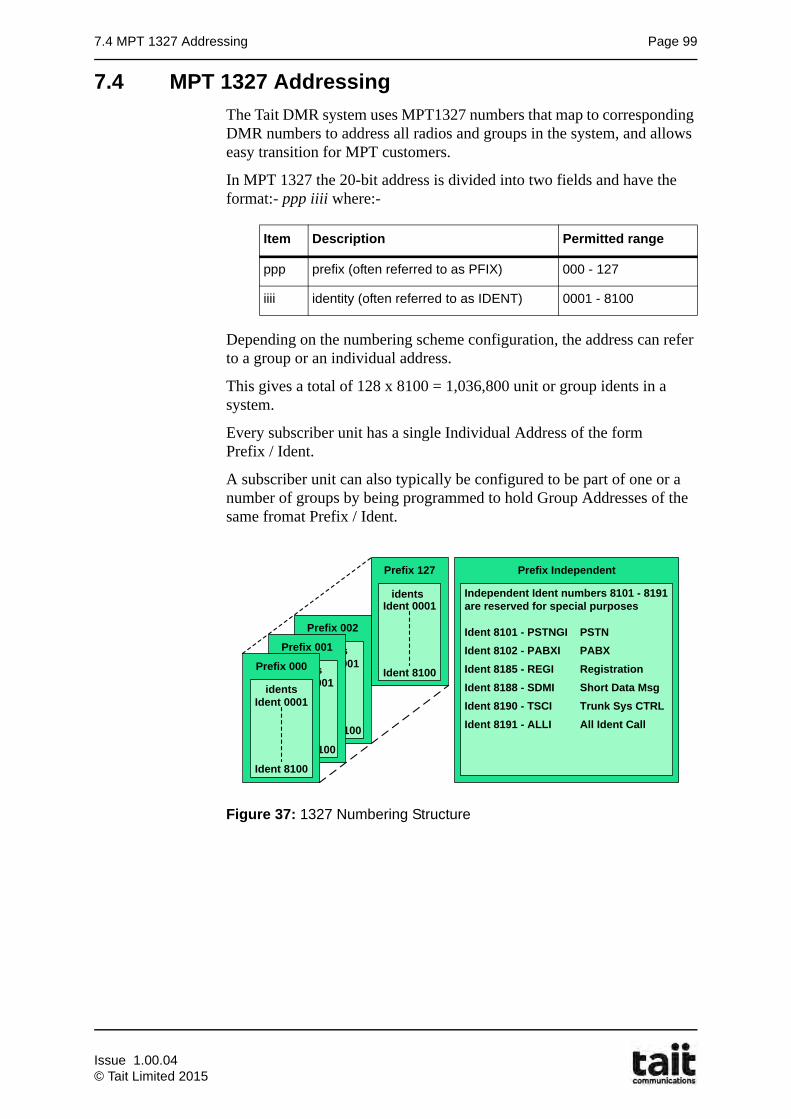
7.4 MPT 1327 Addressing Page 99
7.4 MPT 1327 Addressing
The Tait DMR system uses MPT1327 numbers that map to corresponding DMR numbers to address all radios and groups in the system, and allows easy transition for MPT customers.
In MPT 1327 the 20-bit address is divided into two fields and have the format:- ppp iiii where:-
Depending on the numbering scheme configuration, the address can refer to a group or an individual address.
This gives a total of 128 x 8100 = 1,036,800 unit or group idents in a system.
Every subscriber unit has a single Individual Address of the form Prefix / Ident.
A subscriber unit can also typically be configured to be part of one or a number of groups by being programmed to hold Group Addresses of the same fromat Prefix / Ident.
Figure 37: 1327 Numbering Structure
Item Description Permitted range
ppp prefix (often referred to as PFIX) 000 - 127
iiii identity (often referred to as IDENT) 0001 - 8100
Prefix 127
Ident 0001
Ident 8100
Prefix 002
Ident 0001
Prefix 8100
UsersPrefix 001
Ident 0001
Prefix 8100
UsersPrefix 000
Ident 0001
Ident 8100
idents
Prefix Independent
Independent Ident numbers 8101 - 8191 are reserved for special purposes
Ident 8101 - PSTNGI PSTNIdent 8102 - PABXI PABXIdent 8185 - REGI RegistrationIdent 8188 - SDMI Short Data MsgIdent 8190 - TSCI Trunk Sys CTRLIdent 8191 - ALLI All Ident Call
idents
Issue 1.00.04© Tait Limited 2015
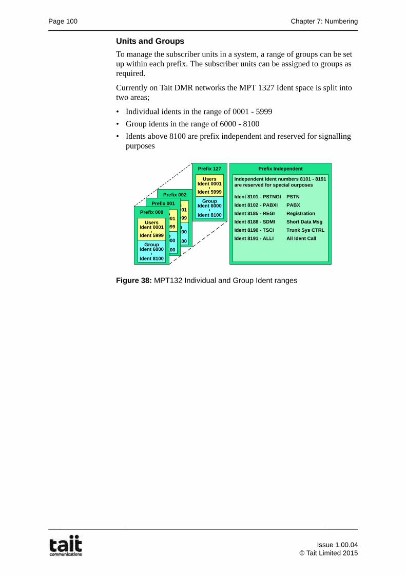
Page 100 Chapter 7: Numbering
Units and Groups
To manage the subscriber units in a system, a range of groups can be set up within each prefix. The subscriber units can be assigned to groups as required.
Currently on Tait DMR networks the MPT 1327 Ident space is split into two areas;
• Individual idents in the range of 0001 - 5999
• Group idents in the range of 6000 - 8100
• Idents above 8100 are prefix independent and reserved for signalling purposes
Figure 38: MPT132 Individual and Group Ident ranges
Prefix 002
Ident 0001
Ident 8100
Users
Ident 5999
Ident 6000Group
Prefix 001
Ident 0001
Ident 8100
Users
Ident 5999
Ident 6000Group
Prefix 000
Ident 0001
Ident 8100
Users
Ident 5999
Ident 6000Group
Prefix Independent
Independent Ident numbers 8101 - 8191 are reserved for special ourposes
Ident 8101 - PSTNGI PSTNIdent 8102 - PABXI PABXIdent 8185 - REGI RegistrationIdent 8188 - SDMI Short Data MsgIdent 8190 - TSCI Trunk Sys CTRLIdent 8191 - ALLI All Ident Call
Prefix 127
Ident 0001
Ident 8100
Users
Ident 5999
Ident 6000Group
Issue 1.00.04
© Tait Limited 2015
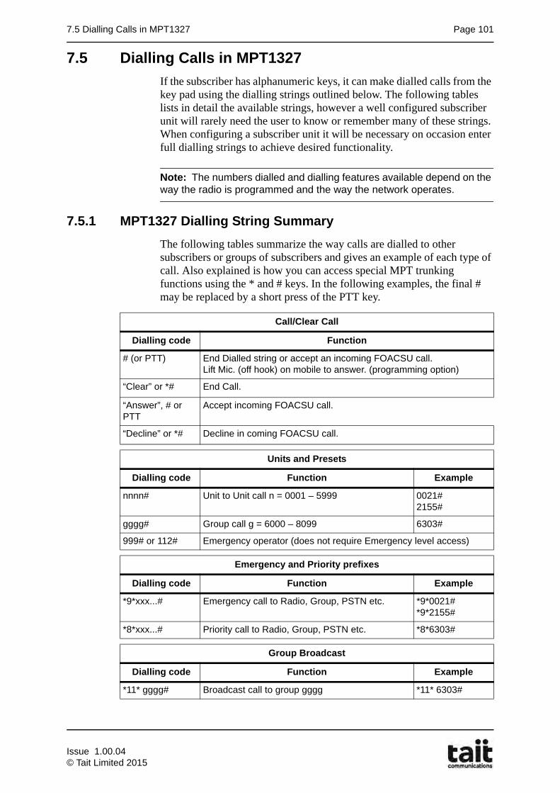
7.5 Dialling Calls in MPT1327 Page 101
7.5 Dialling Calls in MPT1327
If the subscriber has alphanumeric keys, it can make dialled calls from the key pad using the dialling strings outlined below. The following tables lists in detail the available strings, however a well configured subscriber unit will rarely need the user to know or remember many of these strings. When configuring a subscriber unit it will be necessary on occasion enter full dialling strings to achieve desired functionality.
Note: The numbers dialled and dialling features available depend on the way the radio is programmed and the way the network operates.
7.5.1 MPT1327 Dialling String Summary
The following tables summarize the way calls are dialled to other subscribers or groups of subscribers and gives an example of each type of call. Also explained is how you can access special MPT trunking functions using the * and # keys. In the following examples, the final # may be replaced by a short press of the PTT key.
Call/Clear Call
Dialling code Function
# (or PTT) End Dialled string or accept an incoming FOACSU call.Lift Mic. (off hook) on mobile to answer. (programming option)
“Clear” or *# End Call.
“Answer”, # or PTT
Accept incoming FOACSU call.
“Decline” or *# Decline in coming FOACSU call.
Units and Presets
Dialling code Function Example
nnnn# Unit to Unit call n = 0001 – 5999 0021#2155#
gggg# Group call g = 6000 – 8099 6303#
999# or 112# Emergency operator (does not require Emergency level access)
Emergency and Priority prefixes
Dialling code Function Example
*9*xxx...# Emergency call to Radio, Group, PSTN etc. *9*0021#*9*2155#
*8*xxx...# Priority call to Radio, Group, PSTN etc. *8*6303#
Group Broadcast
Dialling code Function Example
*11* gggg# Broadcast call to group gggg *11* 6303#
Issue 1.00.04© Tait Limited 2015
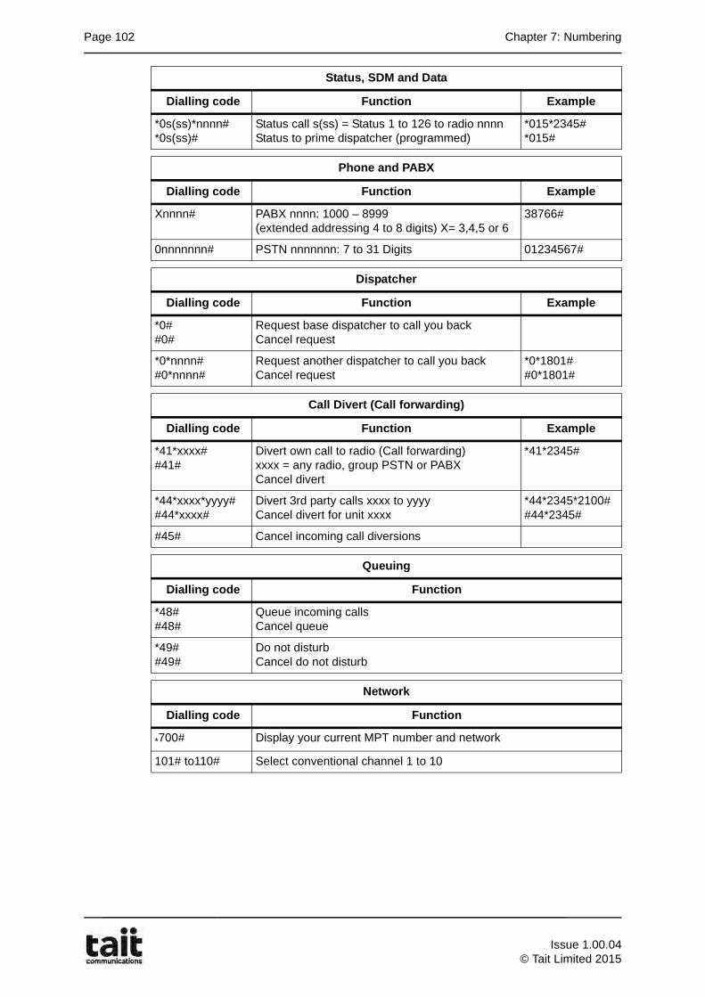
Page 102 Chapter 7: Numbering
Status, SDM and Data
Dialling code Function Example
*0s(ss)*nnnn#*0s(ss)#
Status call s(ss) = Status 1 to 126 to radio nnnnStatus to prime dispatcher (programmed)
*015*2345#*015#
Phone and PABX
Dialling code Function Example
Xnnnn# PABX nnnn: 1000 – 8999 (extended addressing 4 to 8 digits) X= 3,4,5 or 6
38766#
0nnnnnnn# PSTN nnnnnnn: 7 to 31 Digits 01234567#
Dispatcher
Dialling code Function Example
*0##0#
Request base dispatcher to call you backCancel request
*0*nnnn##0*nnnn#
Request another dispatcher to call you backCancel request
*0*1801##0*1801#
Call Divert (Call forwarding)
Dialling code Function Example
*41*xxxx##41#
Divert own call to radio (Call forwarding)xxxx = any radio, group PSTN or PABXCancel divert
*41*2345#
*44*xxxx*yyyy##44*xxxx#
Divert 3rd party calls xxxx to yyyyCancel divert for unit xxxx
*44*2345*2100##44*2345#
#45# Cancel incoming call diversions
Queuing
Dialling code Function
*48##48#
Queue incoming callsCancel queue
*49##49#
Do not disturbCancel do not disturb
Network
Dialling code Function
*700# Display your current MPT number and network
101# to110# Select conventional channel 1 to 10
Issue 1.00.04
© Tait Limited 2015
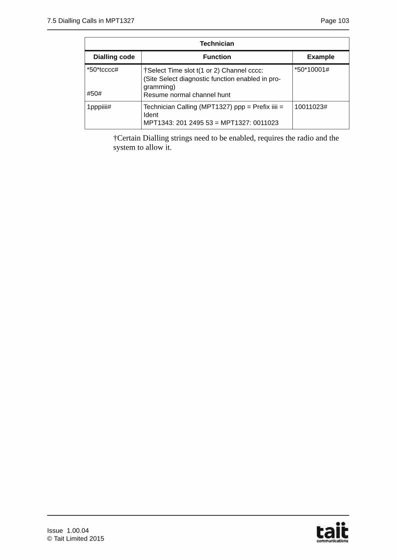
7.5 Dialling Calls in MPT1327 Page 103
†Certain Dialling strings need to be enabled, requires the radio and the system to allow it.
Technician
Dialling code Function Example
*50*tcccc#
#50#
†Select Time slot t(1 or 2) Channel cccc: (Site Select diagnostic function enabled in pro-gramming)Resume normal channel hunt
*50*10001#
1pppiiii# Technician Calling (MPT1327) ppp = Prefix iiii = Ident MPT1343: 201 2495 53 = MPT1327: 0011023
10011023#
Issue 1.00.04© Tait Limited 2015

Page 104 Chapter 7: Numbering
Issue 1.00.04
© Tait Limited 2015