dm50 quick reference
DESCRIPTION
Little documents about connecting a data matrxi and bare code reader DM 50 from COGNEX.document in englishthis document is provided by the builder.TRANSCRIPT

COGNEX®
DataMan® 50Quick Reference Guide

ii DataMan 50 Quick Reference Guide DataMan 50 Quick Reference Guide iii
Section Title • Page 21 Getting Started About DataMan 50 • For More Information • DataMan 50 Systems • DataMan 50 Accessories • Reader Layout
Page 41
DataMan Software Page 173 Installing DataMan Software and Connecting the Reader • Start the Setup Tool • Use the Setup Tool Menu Bar • Triggering • Training the Reader • Read Setups
1 Connections, Optics, and Lighting Page 284 I/O Cable • Digital Input and Output Wiring Diagrams • Illumination Strobe Output • Multi-Port Connections
1 Compliance Information, Warnings and Notices
Page 385 DataMan 50 Specifications • Warnings and Notices • Compliance Statements
Setting Up Your DataMan Setting the Focus Position • Dimensions • DataMan 50 Imager Specifications • Field of View and Reading Distances2 Page 10

4 DataMan 50 Quick Reference Guide DataMan 50 Quick Reference Guide 5
About DataMan 50 For More Information...DataMan 50 is a compact fixed-mount ID reader that among others offers the following advanced features:
• Smallest high-performance fixed mount reader
• Highest read rates for 1-D and 2-D codes
• Reliability and image feedback
The DataMan 50 reader supports RS-232 and USB interface connections in addition to discrete I/O.
The DataMan 50 reader is packaged in a rugged, IP65-rated housing.
This document provides basic information about how to configure and use the DataMan 50 reader. Additional information is available through the Windows Start menu or the Setup Tool Help menu after you install the DataMan software on your PC:
DataMan Fixed Mount Readers Reference is a complete online hardware reference for the DataMan reader. Cognex->DataMan Software v x.x->Documentation->English->DM50->Fixed Mount Reference Manual
DataMan Communications & Programming Guide shows how to integrate your DataMan reader with your automation software and factory network.Cognex->DataMan Software v x.x->Documentation->Communications &Programming
DataMan Reader Configuration Codes provides printable 2-D codes that you can use to configure the DataMan reader.Cognex->DataMan Software v x.x->Documentation->English->Reader Configuration Codes
DataMan Questions and Answers provides context-sensitive information. You can view this help inside the Setup Tool or as a stand-alone help file.Cognex->DataMan Software v x.x->Documentation->English->DM50->Questions and Answers
Release Notes list detailed system requirements and additional information about this DataMan software release.Cognex->DataMan Software v x.x->Documentation->DataMan v x.y.z Release Notes
6 DataMan 50 Quick Reference Guide DataMan 50 Quick Reference Guide 7
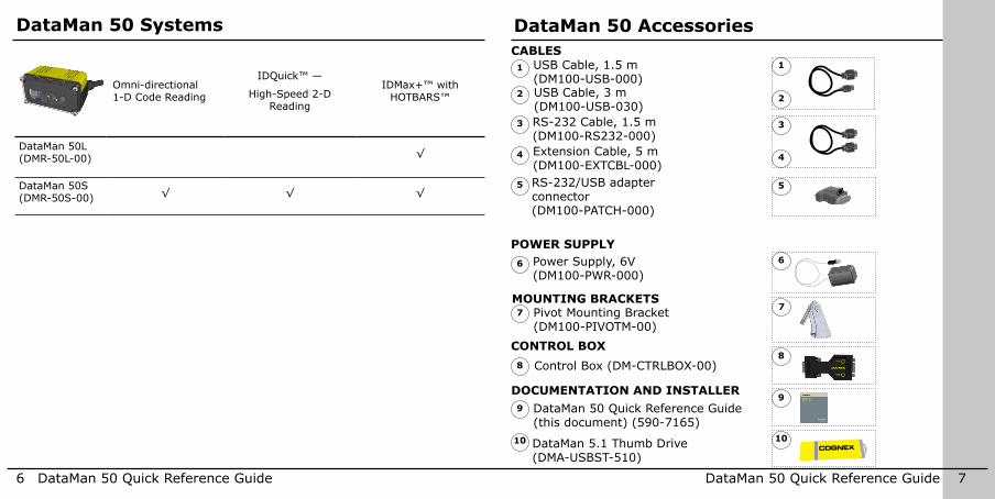
DataMan 50 Systems
Omni-directional 1-D Code Reading
IDQuick™ —
High-Speed 2-D Reading
IDMax+™ with HOTBARS™
DataMan 50L (DMR-50L-00) √
DataMan 50S (DMR-50S-00) √ √ √
DataMan 50 Accessories
USB Cable, 1.5 m (DM100-USB-000)
1
2
1
2
CABLES
8
RS-232 Cable, 1.5 m (DM100-RS232-000)
7MOUNTING BRACKETS
POWER SUPPLY
Pivot Mounting Bracket (DM100-PIVOTM-00)
Power Supply, 6V (DM100-PWR-000)
7
6
4
3
USB Cable, 3 m (DM100-USB-030)
5
Extension Cable, 5 m (DM100-EXTCBL-000)
4
6
5
CONTROL BOX
9
Control Box (DM-CTRLBOX-00) 8
3
9DOCUMENTATION AND INSTALLER
10
DataMan 50 Quick Reference Guide (this document) (590-7165)
DataMan 5.1 Thumb Drive (DMA-USBST-510)
10
RS-232/USB adapter connector (DM100-PATCH-000)

The following image shows the characteristics of the DataMan 50 reader.
8 DataMan 50 Quick Reference Guide DataMan 50 Quick Reference Guide 9
Reader Layout
LED aimer
Mounting holes (M3 x 3.5mm)
Cable
Internal illumination
3-position M12 lens
Status LEDs
Hidden square nut as an alternative mounting option
Remove side cover to access square nut (M3)
yellow arrow indicates selected focus position

10 DataMan 50 Quick Reference Guide DataMan 50 Quick Reference Guide 11
DataMan 50 can operate in one of three distance ranges. To set the focus position:
Remove screws, lens cover, and rubber part.
Set focus by positioning a coin into the lens cap slit and turning the coin. Do not use a coin thicker than 2 mm. If no coin is available, use the edge of the back cover.
Setting the Focus Position
1
2
Make sure that the sealing and the sealing surface are clean before reassembling the lens cover.
3
Line up the holes with the icons, and attach the rubber part to the front window. 4
5 Attach both to housing and add screws.
Tighten screws in order shown. Maximum torque for the cover screws is 8 N-cm (0.7 pound-inch). The yellow arrow on the cover indicates the selected focus position.
6
Lens cap slit

Observe the following DataMan 50 reader dimensions when installing your reader.
12 DataMan 50 Quick Reference Guide DataMan 50 Quick Reference Guide 13
Dimensions
31.751.25
45.401.79
5.670.22
27.401.08
21.650.85
23.44mm0.92in
31.75mm1.25in
45.40mm1.79in
5.67mm0.22in
27.40mm1.08in
21.65mm
0.85in
23.60mm0.93in
23.44mm0.92in
31.75 mm1.25”
45.40 mm1.79”
5.67 mm0.22”
27.40 mm1.08”
21.65 mm0.85”
23.440.92
150mm59.05in

14 DataMan 50 Quick Reference Guide DataMan 50 Quick Reference Guide 15
(40 mm)
mm 20
20
20
40
40
40
60
60
60 80 100 120
34 x 22 50 x 32 77 x 49
140 160 180
DataMan 50 Imager SpecificationsSpecification DataMan 50 Imager
Image Sensor 1/3 inch CMOS
Image Sensor Properties 4.51 mm x 2.88 mm (H x V), 6.0 µm square pixels
Image Resolution (pixels) 752 x 480
Electronic Shutter Speed 33 µs to 25 ms exposure
Image Acquisition up to 60 fps at full resolution
Lens Type 3 focal position M12 lens
Field of ViewThis chart shows the horizontal field of view for the DataMan 50 at a range of working distances.
The horizontal and vertical field of view is shown for working distances of 45mm, 70mm and 110mm.

CONNECT YOUR READER
1. Connect the cable on the back of the device to either an USB adapter cable with power tap or to an RS-232 adapter cable with power tab.
2. Connect either the USB or the RS-232 connector to your PC.
3. Connect a 6V power supply.
16 DataMan 50 Quick Reference Guide DataMan 50 Quick Reference Guide 17
Reading DistancesThis chart shows the supported range of reading distances for four code sizes (6, 8, 10, and 12 mil) at each of the three focus positions (45 mm, 70 mm, and 110 mm).
6 mil
8 mil
10 mil
12 mil
20mm 40 60 80 100 120 140 160 180
45
65
105
40
70110
65
Installing DataMan Software and Connecting the ReaderINSTALL DATAMAN SOFTWARE AND CONNECT
1. Check the DataMan Release Notes for a full list of system requirements.
2. Insert CD-ROM and follow the on-screen prompts until you successfully completed the DataMan Software installation process.
3. Connect the DataMan 50 reader to your PC.
4. Launch the Setup Tool and click Refresh.
Detected readers will appear under COM ports.
5. Select a reader from the list and click Connect.

IN1 button
18 DataMan 50 Quick Reference Guide DataMan 50 Quick Reference Guide 19
Start the Setup ToolTrigger button
Connect the reader to the Setup Tool to configure it with the type of symbologies it will decode as well as other parameters, such as the type of trigger it will use and the format of the results it will generate.
Alternatively, configure your reader by scanning the appropriate reader configuration code from the Reader Configuration Codes document, available through the Windows Start menu or the Setup Tool Help menu.
Quick SetupAll main controls and visual feedback in a single view, for easiest setup and configuration
Connect to ReaderEstablish a connection to the reader
Results DisplayView results
Light and Imager SettingsChoose a trigger type and other acquisition parameters
System SettingsConfigure visual and audio feedback, trigger and output actions
Table ViewSee all the selectable values in the Setup Tool in one table
Latest image
Read history
Context based help
Connection status
Region of interest
Train status
Code information

20 DataMan 50 Quick Reference Guide DataMan 50 Quick Reference Guide 21
Use the Setup Tool Menu BarThe In1 button on the toolbar creates a virtual rising edge signal on Input 1. Use the In1 button to activate various actions such as training a code, optimizing brightness or setting a match string without a physical input 1 channel.
Each reader can store its current set of runtime parameters to a configuration (.cfg) file, which contains information such as the enabled symbologies and how any output data should be formatted.
The same configuration file can be loaded onto multiple readers, as the file does not contain identification information such as the device name of the reader used to create it.
A reader can also generate a Cognex device configuration (.cdc) file, which stores the set of runtime parameters plus any identification data, such as the name of the device. Cognex recommends generating a device configuration file for each reader to allow you to restore a reader to its operating state with minimal effort.
Use the File menu of the Setup Tool to manage .cfg and .cdc files, export parameters, or to load, save, or train uploaded images.
File Menu
Open Configuration Open a saved .cfg configuration file.
Save Configuration Create a .cfg configuration file of current runtime parameters.
Restore Device Load a saved device configuration .cdc file, with runtime parameters plus device-specific information for a particular DataMan reader.
Backup Device Create a device configuration .cdc file for a specific reader.
Export Parameters Save (all or only the non-default) parameters of your device in a text file.
Load Image Load an 8-bit uncompressed grey-scale .bmp or .jpg image for analysis.
Save Image Save the latest acquired image with the .jpg or .bmp file format.
Save Burst Images Save the latest batch of burst images.
Train Image Upload an image to be used for training.

22 DataMan 50 Quick Reference Guide DataMan 50 Quick Reference Guide 23
Use the Setup Tool Menu Bar (Continued)
System Menu
Save Settings Save the current parameters to non-volatile memory, which allows the reader to restore these settings each time you reboot it.
Reset Configuration Reset all configuration parameters in RAM (volatile memory) to the default settings.
Update Firmware Update the reader software.
Upload Feature Key Unlock additional features available in the reader software if you have the right key.
Show Device Log Error and exception conditions, such as missed triggers and trigger overruns are logged.
Delete Device Log Clear your device log.
Use the Help menu to display Setup Tool version information.
Use the Edit menu for standard Cut, Copy and Paste operations.
Use the View menu to view reader information (serial number, firmware version, and so on) and to enable and disable various elements of the Setup Tool, and the Tasks menu to switch between various Setup Tool options.
Use the System menu to manage the current settings on the reader and to upgrade the features it currently supports:
DataMan 50 TriggeringDataMan 50 readers support the following trigger modes: • Self: At an interval you configure, the reader automatically detects
and decodes codes in its field of view. If you set a higher re-read delay than the trigger interval, there is a code output only once until the code is out of the field of view for the duration of the re-read delay.
• Single (external trigger): Acquires a single image and attempts to decode any symbol it contains, or more than one symbol in cases where multicode is enabled. The reader relies on an external trigger source.
• Presentation: Scans, decodes and reports a single code in the field of view. The reader relies on an internal timing mechanism to acquire images.
• Manual: Begins acquiring images when you send an external trigger, and continues acquiring images until a symbol is found and decoded or you stop the external triggering.
• Burst: Performs multiple image acquisitions based on an external trigger and decodes any symbol appearing in a single image or within a sequence of images, or multiple symbols in a single image or within a sequence of images when multicode is enabled. You can control the number of images within each burst and the interval between image acquisitions.
• Continuous: Begins acquiring images based on a single external trigger and continues to acquire and decode images until a symbol is found and decoded, or until multiple images containing as many codes as specified in multicode mode are located, or until the trigger is released. You can configure your reader to acquire images based on the start and stop signal from separate digital IO pulses.

24 DataMan 50 Quick Reference Guide DataMan 50 Quick Reference Guide 25
External TriggersIf you are using external triggering you can use any of these methods to trigger your DataMan 50 series reader:
• Send a pulse on the I/O cable:
• Input 0 (white)
• Input 1 (white/black)
• Send a serial trigger command over the RS-232 connection.
• Press <CTRL>-T on the keyboard while the Setup Tool has the input focus.
• Click the Trigger button in the Setup Tool:
Training the ReaderTraining your reader with the expected symbology can make the time required to decode successive symbols more consistent. In addition, training may help increase decode yield.
To train your reader, place a code in front of the reader and do one of the following:
• Click and hold the trigger button in the Setup Tool for a minimum of 3 seconds.
• Click Train Code in the Results Display pane.
You can use training in Single, Burst, Continuous or Self trigger modes.
NOTE that only a single symbol of each symbology kind can be trained.
• Upload the code through File menu Train Image.

Read Setups
Your reader can be configured for up to 16 different settings. In Single trigger mode, you can enable multiple (or all) setups, and the DataMan 50 reader goes through all of the configured imager combinations until there is a decoded image or there are no images left (that is, a no read image).You can change the parameters for the setups either on its dedicated pane, or in the Read Setup pane’s appropriate table cell. Whatever you change on either pane is mirrored on the other.The read setup process starts with either a specific setup, or the Last Successful Decode (as you choose).
It is possible to configure a variety of acquisition parameters for your DataMan 50 reader on a unified Read Setups pane.
The currently selected setup also gets represented on other panes.
26 DataMan 50 Quick Reference Guide DataMan 50 Quick Reference Guide 27
Incremental Training for Multiple SymbologiesIf you want to train the reader to recognize multiple symbologies, you can present a single image showing all the desired symbologies and perform the training procedure previously described.
If you cannot present a single image showing all the necessary symbologies, you can enable incremental training on the Training tab of the Symbology Settings pane:
With incremental training enabled, you can train the reader using multiple images showing the symbologies you expect to decode. The reader will train each new symbology while retaining the existing trained symbologies.
Training the Reader (Continued)
1
2
3
4
5
6
7
8
9
10
11
12
13
14
15
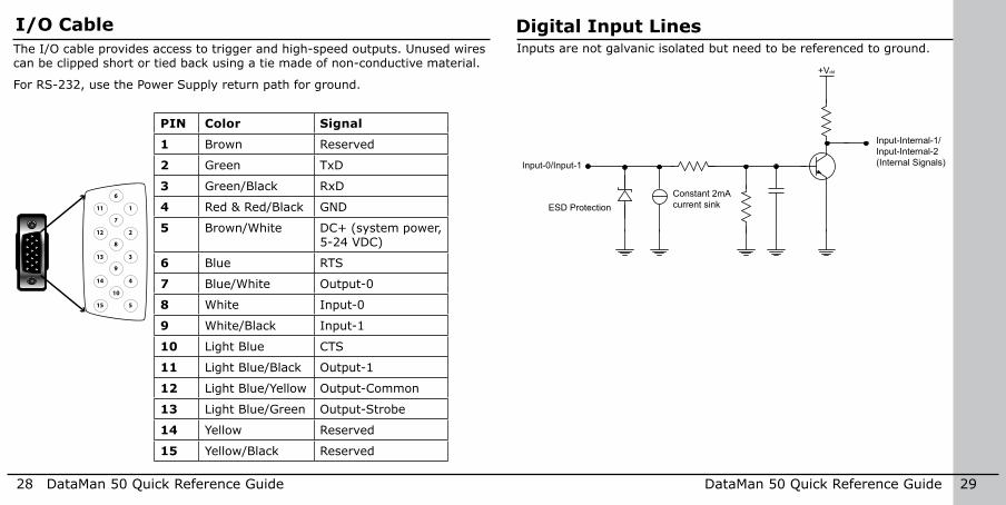
PIN Color Signal
1 Brown Reserved
2 Green TxD
3 Green/Black RxD
4 Red & Red/Black GND
5 Brown/White DC+ (system power, 5-24 VDC)
6 Blue RTS
7 Blue/White Output-0
8 White Input-0
9 White/Black Input-1
10 Light Blue CTS
11 Light Blue/Black Output-1
12 Light Blue/Yellow Output-Common
13 Light Blue/Green Output-Strobe
14 Yellow Reserved
15 Yellow/Black Reserved
28 DataMan 50 Quick Reference Guide DataMan 50 Quick Reference Guide 29
I/O CableThe I/O cable provides access to trigger and high-speed outputs. Unused wires can be clipped short or tied back using a tie made of non-conductive material.
For RS-232, use the Power Supply return path for ground.
Digital Input LinesInputs are not galvanic isolated but need to be referenced to ground.
Input-0/Input-1
ESD Protection Constant 2mAcurrent sink
Input-Internal-1/Input-Internal-2(Internal Signals)
+Vdd

30 DataMan 50 Quick Reference Guide DataMan 50 Quick Reference Guide 31
Digital Output LinesThe digital outputs can be used as either NPN (pull-down) or PNP (pull-up) lines. For NPN lines, the external load should be connected between the output and the positive supply voltage (<26V). The outputs pull down to less than 3V when ON, which causes current to flow through the load. When the outputs are OFF, no current flows through the load. Outputs are not galvanic isolated but need to be referenced to ground.
Output_Common
Output_IOPTCDSP output signal 50mA
NPN (pull down) output type characteristics are the following:
Applied voltage 26 VDC or less
Residual voltage 0.85V or less
Maximum sink current 25mA
Short-circuit current 100mA or less
Short-circuit protection multifuse - 50mA
PNP (pull up) output type characteristics are the following:
Output voltage range 26V or less
Residual voltage 0.8V or less
Maximum source current 25mA
Short-circuit current 50mA or less
Short-circuit protection multifuse - 50mA

32 DataMan 50 Quick Reference Guide DataMan 50 Quick Reference Guide 33
Illumination Strobe OutputThe strobe output is provided by a diode that is added to the push-pull circuit, with series to the pull-up transistor. This diode blocks the higher voltage when the output is pulled up when used as open-collector type driving, but enables the driving of high level in TTL mode.
TTL output type characteristics are the following:
High level 4.0-5.0V
Low level 0-0.4V
Output current 25mA
Short-circuit current 125mA
Short-circuit protection multifuse - 50mA
Open-collector output type characteristics are the following:
Output voltage range 0-26V
Low level 0-0.4V
Output current 25mA max
Short-circuit current 125mA
Short-circuit protection multifuse - 50mA
The following figure shows the wiring diagram of the illumination strobe output.
+5VDC
Output-Strobe
ESD Protection Strobe (Internal signal)

34 DataMan 50 Quick Reference Guide DataMan 50 Quick Reference Guide 35
You can connect multiple DataMan 50 readers to a single PC (or other device equipped with a serial port) using a multi-port connection.
A multi-port connection creates a daisy-chain of readers. Each reader receives serial data from the previous reader and transmits it to the next reader. When a reader transmits data, it is passed through each of the readers in the chain between it and the PC.
Because of the large number of possible configurations, Cognex does not supply cabling for multi-port DataMan 50 connections. Instead, you must construct your own cable that meets the requirements of your system configuration.The cable must provide a DB-9 connector for each DataMan 50 serial cable and a DB-9 connector for the PC serial port. Each DB-9 connector must provide Tx
Multi-Port Connections
2
3
5
532 532 532
DataMan 50
2: Tx Data3: Rx Data5: GND
2: Rx Data3: Tx Data5: GND
PC
DataMan 50 DataMan 50
Data, Rx Data, and ground. The Tx Data and Rx Data pins on adjacent connectors must be connected to provide the multi-port connection.
The following diagram shows how to create a multi-port cable for a 3-reader system:

36 DataMan 50 Quick Reference Guide DataMan 50 Quick Reference Guide 37
Configuring for Multi-Port OperationYou must connect the Setup Tool to each DataMan 50 in turn and enable multi-port operation. Click the Communication Settings task and check the Enable Multi-Port (RS-232 Sharing) check box.
There is no guaranteed delivery order when multiple readers transmit data using a multi-port connection; read results may arrive at the PC in any order. You can configure each DataMan 50 reader in a multi-port connection to add identifying data to each read result. Your PC application can then determine which reader produced a specific read result.
To do this, click on the Data Formatting task, click the appropriate Standard box (for each symbology that you are using), go to the Standard Formatting pane, and enter text in the Leading Text field. (You can also add trailing text by entering text in the Terminating Text field.)
You can obtain the best results when using multi-port connections by keeping the following usage guidelines in mind as you design your system:
• The maximum cable length between any two DataMan readers or between the PC and any DataMan reader should be no greater than 15 meters.
• There is no fixed limit to the number of DataMan readers that you can connect to a single PC. Each reader introduces a delay of about 100 msec when it retransmits received serial data. If you have 5 readers, this means that there will be a 400 msec delay between the time the first reader in the chain transmits data and the PC receives it.
• Each DataMan reader must receive a hardware trigger signal on its Input 0 line. You can wire the input ports to a common trigger signal or you can provide individual triggers for each reader.
• If any reader in the multi-port chain loses power or becomes disconnected, then no data from any other reader will be transmitted.
• If a DataMan is transmitting its own read result, it will buffer any data received from another reader until it has finished its own data transmission. If a DataMan reader is transmitting another reader’s data, it will buffer its own data if it receives a trigger signal while it is processing the other reader’s data.
• If you use a single power supply for multiple readers, make sure that the power supply can provide enough power for all of the readers.
• You cannot connect a reader to the Setup Tool over RS-232 once multiport is enabled. You must first scan the Disable Multi-Port code from the Reader Configuration Codes, available from the Start menu.
Multi-Port Usage Notes

38 DataMan 50 Quick Reference Guide DataMan 50 Quick Reference Guide 39
DataMan 50 Specifications Weight 76 g (including cable)
Operating Temperature 0ºC — 40ºC (32ºF — 104ºF)
Storage Temperature -10ºC — 60ºC (-14ºF — 140ºF)
Maximum Humidity 95% (non-condensing)
Environmental IP65
Vibration EN61373 including IEC 60068-2-6,60068-2-64 6.4, and 60068-2-27
Codes Data MatrixTM (IDMax: ECC 0, 50, 80, 100, 140, and 200; IDQuick: ECC200)Vericode (optional)
QR Code and microQR Code, MaxiCodeUPC/EAN/JAN
Codabar, Interleaved 2 of 5, Code 39, Code 128, and Code 93, Pharma, Postal, RSS/CS, PDF 417, MicroPDF 417
Discrete I/O operating limits
Output 0,1 IMAX @ 24 VDC 25 mAVMAX 26 V
Output 2 Source VTYP 4 V
Sink VIH 4 - VPSU V VIL 0 — 2 V
Input 0 (Trigger)Input 1
VIH 4 — 26 VVIL 0 — 2 VITYP 3 mA
Power Supply Requirements
VPSU 4,5 — 26 VDC 2.5 W maximum LPS or NEC class 2 power supply
i NOTE: For product support, contact http://support.cognex.com
CAUTION: IP protection is ensured only when all connectors are attached to cables or shielded by a sealing cap.
Warnings and Notices
CAUTION: LED RADIATION - DO NOT VIEW DIRECTLY WITH OPTICAL INSTRUMENTS - CLASS 1M LED PRODUCT

40 DataMan 50 Quick Reference Guide DataMan 50 Quick Reference Guide 41
computers, etc.) that is not CE marked and does not comply with the Low Voltage Directive.
For European Community UsersCognex complies with Directive 2002/96/EC OF THE EUROPEAN PARLIAMENT AND OF THE COUNCIL of 27 January 2003 on waste electrical and electronic equipment (WEEE).
This product has required the extraction and use of natural resources for its production. It may contain hazardous substances that could impact health and the environment, if not properly disposed.
In order to avoid the dissemination of those substances in our environment and to diminish the pressure on the natural resources, we encour-age you to use the appropriate take-back systems for product disposal. Those systems will reuse or recycle most of the materials of the product you are disposing in a sound way.
The crossed out wheeled bin symbol informs you that the product should not be disposed of along with municipal waste and invites you to use the appropriate separate take-back systems for product disposal.
If you need more information on the collection, reuse, and recycling systems, please contact your
local or regional waste administration.
You may also contact your supplier for more information on the environmental performance of this product.
DataMan 50 readers meet or exceed the require-ments of all applicable standards organizations for safe operation. However, as with any electrical equipment, the best way to ensure safe operation is to operate them according to the agency guidelines that follow. Please read these guidelines carefully before using your device.
Regulator SpecificationUSA FCC Part 15, Subpart B, Class ACanada ICES-003, Class AEuropean Community
EN55022:2006 +A1:2007, Class AEN55024:1998 +A1:2001 +A2: 2003
Australia C-TICK, AS/NZS CISPR 22 / EN 55022 for Class A Equipment
Japan J55022, Class A
FCC Class A Compliance Statement
This equipment has been tested and found to comply with the limits for a Class A digital device, pursuant to Part 15 of the FCC rules. These limits are designed to provide reasonable protection against harmful interference when the equipment is oper-ated in a commercial environment. This equipment generates, uses, and can radiate radio frequency energy and, if not installed and used in accordance with the instructions, may cause harmful interfer-ence to radio communications. Operation of this
equipment in a residential area is likely to cause harmful interference, in which case the user will be required to correct the interference at personal expense.
Canadian ComplianceThis Class A digital apparatus complies with Canadian ICES-003.Cet appareil numérique de la classe A est conforme à la norme NMB-003 du Canada.
C-Tick Statement
Conforms to AS/NZS CISPR 22/ EN 55022 for Class A Equipment.
European Compliance
The CE mark on the product indicates that the system has been tested to and conforms to the provisions noted within the 2004/108/EEC Electromagnetic Com-patibility Directive.
For further information please contact: Cognex Corporation One Vision Drive Natick, MA 01760 USA
Cognex Corporation shall not be liable for use of our product with equipment (i.e., power supplies, personal
Compliance Statements

P/N 590-7165
Copyright © 2013 Cognex Corporation All Rights Reserved. This document may not be copied in whole or in part, nor transferred to any other media or language, without the written permission of Cognex Corporation. The hardware and portions of the software described in this document may be covered by one or more of the U.S. patents listed on the Cognex web site http://www.cognex.com/patents.asp. Other U.S. and foreign
patents are pending. Cognex, the Cognex logo, and DataMan are trademarks, or registered trademarks, of Cognex Corporation.
Reader Programming Codes
Reset Scanner to Factory Defaults Reboot Scanner