dm nvx av-over-ip system
TRANSCRIPT

DM NVX™ AV-over-IP System
Design Guide Crestron Electronics, Inc.

Original Instructions
The U.S. English version of this document is the original instructions.
All other languages are a translation of the original instructions.
Crestron product development software is licensed to Crestron dealers and Crestron Service Providers (CSPs) under a
limited non-exclusive, non-transferable Software Development Tools License Agreement. Crestron product operating system
software is licensed to Crestron dealers, CSPs, and end-users under a separate End-User License Agreement. Both of these
Agreements can be found on the Crestron website at www.crestron.com/legal/software_license_agreement.
The product warranty can be found at www.crestron.com/legal/sales-terms-conditions-warranties.
The specific patents that cover Crestron products are listed at www.crestron.com/legal/patents.
Certain Crestron products contain open source software. For specific information, visit
www.crestron.com/legal/open-source-software.
Crestron, the Crestron logo, .AV Framework, AirMedia, Cresnet, Crestron Studio, Crestron Toolbox, Crestron XiO Cloud,
DigitalMedia, DM NVX, DM NVX Director, QuickSwitch HD, and Saros are either trademarks or registered trademarks of
Crestron Electronics, Inc. in the United States and/or other countries. Blu-ray is either a trademark or registered trademark
of the Blu-ray Disc Association in the United States and/or other countries. Audinate and Dante are either trademarks or
registered trademarks of Audinate Pty Ltd. in the United States and/or other countries. Dolby, Dolby Atmos, and Dolby
Digital are either trademarks or registered trademarks of Dolby Laboratories in the United States and/or other countries.
DTS, DTS HD, and DTS HD Master Audio are either trademarks or registered trademarks of DTS, Inc. in the United States
and/or other countries. HDMI and the HDMI logo are either trademarks or registered trademarks of HDMI Licensing LLC in
the United States and/or other countries. Intel is a trademark or registered trademark of Intel Corporation in the United
States and/or other countries. Active Directory, Microsoft, and Windows are either trademarks or registered trademarks of
Microsoft Corporation in the United States and/or other countries. DisplayPort is either a trademark or registered
trademark of Video Electronics Standards Association in the United States and/or other countries. Other trademarks,
registered trademarks, and trade names may be used in this document to refer to either the entities claiming the marks and
names or their products. Crestron disclaims any proprietary interest in the marks and names of others. Crestron is not
responsible for errors in typography or photography.
©2019 Crestron Electronics, Inc.

Design Guide – DOC. 7977G Contents • i
Contents Introduction .................................................................................................................................... 1
System Design ...............................................................................................................................2
Endpoint Design ......................................................................................................................................... 2 DM NVX Endpoints ............................................................................................................................. 2 DM NVX Director Virtual Switching Appliances .......................................................................... 11 SFP-1G and SFP-10G Transceiver Modules ................................................................................. 12 Endpoint Bandwidth Design and Management ......................................................................... 13 Endpoint Design Considerations ................................................................................................... 15
Network Design ........................................................................................................................................ 16 Minimum Network Requirements .................................................................................................. 16 Network Design Overview ............................................................................................................... 16 Network Topologies .......................................................................................................................... 18 Network Multicast Functionality ................................................................................................... 21 Network Security ............................................................................................................................... 22 Network Design Considerations .................................................................................................... 23
System Installation .................................................................................................................... 25
Endpoint Installation ............................................................................................................................... 25 Network Installation ................................................................................................................................ 27 Crestron Service Provider Handoff ...................................................................................................... 28
Case Studies ............................................................................................................................... 29
Case Study 1: Community College 4K AV Distribution Network ................................................... 29 Case Study 2: 4K Residential AV Distribution Network ................................................................... 31 Case Study 3: 4K AV Distribution over Fiber ...................................................................................... 33
Glossary ....................................................................................................................................... 35


Design Guide – DOC. 7977G DM NVX System • 1
Introduction
A Crestron® DM NVX™ AV-over-IP system is a digital video and audio distribution system
that switches 4K video sources and displays at 60 frames per second (fps) with full 4:4:4
color sampling and High Dynamic Range (HDR) video support. Using standard 1-Gigabit
Ethernet infrastructure, a DM NVX system provides a highly flexible, cost-effective,
and infinitely scalable network AV solution.
Pixel Perfect Processing technology is incorporated into a DM NVX system to provide
flawless video transport in all applications. A video signal is encoded and decoded to
achieve imperceptible end-to-end latency of less than 1 frame. The image quality of the
source is maintained across a 1-Gigabit network at any resolution up to 4K60 4:4:4.
A variety of DM NVX endpoints are available offering flexibility in endpoint selection.
In addition to surface-mountable and card-based form factors, the endpoints are
available as encoder-only, decoder-only, and combined encoder/decoder products.
A DM NVX Director™ virtual switching appliance can be added to configure, control, and
manage a DM NVX system.
This guide aids in the design and installation of a DM NVX system. The guide provides
information about the following:
• System design, which includes endpoint and network design
• System installation, which includes endpoint and network installation
• Case studies
In addition, a glossary is provided at the end of the guide.

2 • DM NVX System Design Guide – DOC. 7977G
System Design
The following sections provide design information related to DM NVX endpoints and the
network.
Endpoint Design
A DM NVX system is composed of one or more encoder endpoints and one or more
decoder endpoints. Additional components of a DM NVX system include the DM NVX
Director virtual switching appliances and SFP (Single Form-factor Pluggable)
transceiver modules.
The following sections provide information about DM NVX endpoints, DM NVX Director
virtual switching appliances, SFP modules, and related system design considerations.
DM NVX Endpoints
DM NVX endpoints are available in three form factors:
1. Surface-mountable endpoints, which provide a compact design that allows an
easy fit in various types of locations, for example, behind a flat panel display
2. OPS (Open Pluggable Specification) endpoint, which is compatible with the Intel®
OPS standard and provides integration with an OPS-supported display
3. Chassis-based cards, which are used with the DMF-CI-8 card chassis for sources
in close proximity to a rack or for applications requiring a high density of
endpoints
Surface-Mountable Endpoints
Surface-mountable endpoints consist of the following models:
• DM-NVX-35x Series encoders/decoders (DM-NVX-350, DM-NVX-351,
and DM-NVX-352)
• DM-NVX-E30 encoder
• DM-NVX-D30 decoder
DM-NVX-350 and DM-NVX-351 Front and Rear Views

Design Guide – DOC. 7977G DM NVX System • 3
DM-NVX-352 Front and Rear Views
DM-NVX-E30 Front and Rear Views
DM-NVX-D30 Front and Rear Views
OPS Endpoint
An OPS endpoint is available with the DM-NVX-D80-IOAV. The endpoint is designed for
installation into the OPS slot of an OPS-supported display.
DM-NVX-D80-IOAV Front and Rear Views

4 • DM NVX System Design Guide – DOC. 7977G
Chassis-Based Cards
Chassis-based cards consist of the following models:
• DM-NVX-35xC Series encoders/decoders (DM-NVX-350C, DM-NVX-351C, and
DM-NVX-352C)
• DM-NVX-E30C encoder
• DM-NVX-D30C decoder
DM-NVX-350C and DM-NVX-351C
DM-NVX-352C
DM-NVX-E30C
DM-NVX-D30C
Design Guide – DOC. 7977G DM NVX System • 5
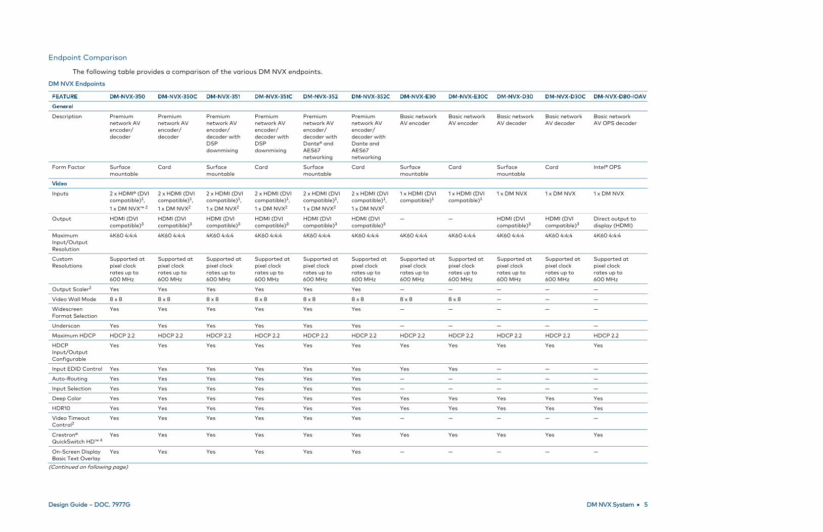
Endpoint Comparison
The following table provides a comparison of the various DM NVX endpoints.
DM NVX Endpoints
Description Premium
network AV
encoder/
decoder
Premium
network AV
encoder/
decoder
Premium
network AV
encoder/
decoder with
DSP
downmixing
Premium
network AV
encoder/
decoder with
DSP
downmixing
Premium
network AV
encoder/
decoder with
Dante® and
AES67
networking
Premium
network AV
encoder/
decoder with
Dante and
AES67
networking
Basic network
AV encoder
Basic network
AV encoder
Basic network
AV decoder
Basic network
AV decoder
Basic network
AV OPS decoder
Form Factor Surface
mountable
Card Surface
mountable
Card Surface
mountable
Card Surface
mountable
Card Surface
mountable
Card Intel® OPS
Inputs 2 x HDMI® (DVI
compatible)1,
1 x DM NVX™ 2
2 x HDMI (DVI
compatible)1,
1 x DM NVX2
2 x HDMI (DVI
compatible)1,
1 x DM NVX2
2 x HDMI (DVI
compatible)1,
1 x DM NVX2
2 x HDMI (DVI
compatible)1,
1 x DM NVX2
2 x HDMI (DVI
compatible)1,
1 x DM NVX2
1 x HDMI (DVI
compatible)1
1 x HDMI (DVI
compatible)1
1 x DM NVX 1 x DM NVX 1 x DM NVX
Output HDMI (DVI
compatible)3
HDMI (DVI
compatible)3
HDMI (DVI
compatible)3
HDMI (DVI
compatible)3
HDMI (DVI
compatible)3
HDMI (DVI
compatible)3
— — HDMI (DVI
compatible)3
HDMI (DVI
compatible)3
Direct output to
display (HDMI)
Maximum
Input/Output
Resolution
4K60 4:4:4 4K60 4:4:4 4K60 4:4:4 4K60 4:4:4 4K60 4:4:4 4K60 4:4:4 4K60 4:4:4 4K60 4:4:4 4K60 4:4:4 4K60 4:4:4 4K60 4:4:4
Custom
Resolutions
Supported at
pixel clock
rates up to
600 MHz
Supported at
pixel clock
rates up to
600 MHz
Supported at
pixel clock
rates up to
600 MHz
Supported at
pixel clock
rates up to
600 MHz
Supported at
pixel clock
rates up to
600 MHz
Supported at
pixel clock
rates up to
600 MHz
Supported at
pixel clock
rates up to
600 MHz
Supported at
pixel clock
rates up to
600 MHz
Supported at
pixel clock
rates up to
600 MHz
Supported at
pixel clock
rates up to
600 MHz
Supported at
pixel clock
rates up to
600 MHz
Output Scaler2 Yes Yes Yes Yes Yes Yes — — — — —
Video Wall Mode 8 x 8 8 x 8 8 x 8 8 x 8 8 x 8 8 x 8 8 x 8 8 x 8 — — —
Widescreen
Format Selection
Yes Yes Yes Yes Yes Yes — — — — —
Underscan Yes Yes Yes Yes Yes Yes — — — — —
Maximum HDCP HDCP 2.2 HDCP 2.2 HDCP 2.2 HDCP 2.2 HDCP 2.2 HDCP 2.2 HDCP 2.2 HDCP 2.2 HDCP 2.2 HDCP 2.2 HDCP 2.2
HDCP
Input/Output
Configurable
Yes Yes Yes Yes Yes Yes Yes Yes Yes Yes Yes
Input EDID Control Yes Yes Yes Yes Yes Yes Yes Yes — — —
Auto-Routing Yes Yes Yes Yes Yes Yes — — — — —
Input Selection Yes Yes Yes Yes Yes Yes — — — — —
Deep Color Yes Yes Yes Yes Yes Yes Yes Yes Yes Yes Yes
HDR10 Yes Yes Yes Yes Yes Yes Yes Yes Yes Yes Yes
Video Timeout
Control2
Yes Yes Yes Yes Yes Yes — — — — —
Crestron®
QuickSwitch HD™ 4
Yes Yes Yes Yes Yes Yes Yes Yes Yes Yes Yes
On-Screen Display
Basic Text Overlay
Yes Yes Yes Yes Yes Yes — — — — —
(Continued on following page)

6 • DM NVX System Design Guide – DOC. 7977G
DM NVX Endpoints (Continued)
Inputs 2 x HDMI,
1 x DM NVX2,
5-pin Phoenix
2 x HDMI,
1 x DM NVX2,
5-pin Phoenix
2 x HDMI,
1 x DM NVX2,
5-pin Phoenix
2 x HDMI,
1 x DM NVX2,
5-pin Phoenix
2 x HDMI,
1 x DM NVX2,
5-pin Phoenix
Dante and
AES67
2 x HDMI,
1 x DM NVX2,
5-pin Phoenix
Dante and
AES67
1 x HDMI 1 x HDMI 1 x DM NVX 1 x DM NVX 1 x DM NVX
Outputs 1 x HDMI,
1 x DM NVX2,
5-pin Phoenix
1 x HDMI,
1 x DM NVX2,
5-pin Phoenix
1 x HDMI,
1 x DM NVX2,
5-pin Phoenix
1 x HDMI,
1 x DM NVX2,
5-pin Phoenix
1 x HDMI,
1 x DM NVX2,
5-pin Phoenix
Dante and
AES67
1 x HDMI,
1 x DM NVX2,
5-pin Phoenix
Dante and
AES67
5-pin Phoenix 5-pin Phoenix 1 x HDMI,
5-pin Phoenix
1 x HDMI,
5-pin Phoenix
OPS
Digital Input/
Output Audio
Formats
Dolby Digital®,
Dolby Digital
EX, Dolby
Digital Plus,
Dolby® TrueHD,
Dolby Atmos®,
DTS®, DTS ES,
DTS 96/24,
DTS HD® High
Res, DTS HD
Master Audio™,
LPCM up to 8
channels
Dolby Digital,
Dolby Digital
EX, Dolby
Digital Plus,
Dolby TrueHD,
Dolby Atmos,
DTS, DTS ES,
DTS 96/24,
DTS HD High
Res, DTS HD
Master Audio,
LPCM up to 8
channels
Dolby Digital,
Dolby Digital
EX, Dolby
Digital Plus,
Dolby TrueHD,
Dolby Atmos,
DTS, DTS ES,
DTS 96/24,
DTS HD High
Res, DTS HD
Master Audio,
LPCM up to 8
channels
Dolby Digital,
Dolby Digital
EX, Dolby
Digital Plus,
Dolby TrueHD,
Dolby Atmos,
DTS, DTS ES,
DTS 96/24,
DTS HD High
Res, DTS HD
Master Audio,
LPCM up to 8
channels
Dolby Digital,
Dolby Digital
EX, Dolby
Digital Plus,
Dolby TrueHD,
Dolby Atmos,
DTS, DTS ES,
DTS 96/24,
DTS HD High
Res, DTS HD
Master Audio,
LPCM up to 8
channels
Dolby Digital,
Dolby Digital
EX, Dolby
Digital Plus,
Dolby TrueHD,
Dolby Atmos,
DTS, DTS ES,
DTS 96/24,
DTS HD High
Res, DTS HD
Master Audio,
LPCM up to 8
channels
Dolby Digital,
Dolby Digital
EX, Dolby
Digital Plus,
Dolby TrueHD,
Dolby Atmos,
DTS, DTS ES,
DTS 96/24,
DTS HD High
Res, DTS HD
Master Audio,
LPCM up to 8
channels
Dolby Digital,
Dolby Digital
EX, Dolby
Digital Plus,
Dolby TrueHD,
Dolby Atmos,
DTS, DTS ES,
DTS 96/24,
DTS HD High
Res, DTS HD
Master Audio,
LPCM up to 8
channels
Dolby Digital,
Dolby Digital
EX, Dolby
Digital Plus,
Dolby TrueHD,
Dolby Atmos,
DTS, DTS ES,
DTS 96/24,
DTS HD High
Res, DTS HD
Master Audio,
LPCM up to 8
channels
Dolby Digital,
Dolby Digital
EX, Dolby
Digital Plus,
Dolby TrueHD,
Dolby Atmos,
DTS, DTS ES,
DTS 96/24,
DTS HD High
Res, DTS HD
Master Audio,
LPCM up to 8
channels
Dolby Digital,
Dolby Digital
EX, Dolby
Digital Plus,
Dolby TrueHD,
Dolby Atmos,
DTS, DTS ES,
DTS 96/24,
DTS HD High
Res, DTS HD
Master Audio,
LPCM up to 8
channels
DSP Audio
Downmix
— — Yes Yes — — — — — — —
Analog Output
Audio Formats
Stereo
2-channel
Stereo
2-channel
Stereo
2-channel
Stereo
2-channel
Stereo
2-channel
Stereo
2-channel
Stereo
2-channel
Stereo
2-channel
Stereo
2-channel
Stereo
2-channel
—
Analog Input
Audio Formats
Stereo
2-channel
Stereo
2-channel
Stereo
2-channel
Stereo
2-channel
Stereo
2-channel
Stereo
2-channel
— — — — —
Secondary Audio
Stream Formats
Stereo
2-channel
Stereo
2-channel
Stereo
2-channel
Stereo
2-channel
Stereo
2-channel
Stereo
2-channel
— — — — —
Dante and AES67
Audio Formats5
— — — — Stereo
2-channel
48 kHz
Stereo
2-channel
48 kHz
— — — — —
Breakaway Audio6 Yes Yes Yes Yes Yes Yes — — — — —
Primary AV
Stream
Yes Yes Yes Yes Yes Yes Yes Yes Yes Yes Yes
Secondary Audio
Stream
Yes Yes Yes Yes Yes Yes — — — — —
Dante Audio
Stream Transmit/
Receive
— — — — Yes Yes — — — — —
AES67 Secondary
Audio Stream
Transmit/Receive
— — — — Yes Yes — — — — —
(Continued on following page)

Design Guide – DOC. 7977G DM NVX System • 7
DM NVX Endpoints (Continued)
Codec Type Pixel Perfect
Processing
Pixel Perfect
Processing
Pixel Perfect
Processing
Pixel Perfect
Processing
Pixel Perfect
Processing
Pixel Perfect
Processing
Pixel Perfect
Processing
Pixel Perfect
Processing
Pixel Perfect
Processing
Pixel Perfect
Processing
Pixel Perfect
Processing
RTP Yes Yes Yes Yes Yes Yes Yes Yes Yes Yes Yes
RTSP Yes Yes Yes Yes Yes Yes Yes Yes Yes Yes Yes
SDP Yes Yes Yes Yes Yes Yes Yes Yes Yes Yes Yes
MPEG2-TS Yes Yes Yes Yes Yes Yes Yes Yes Yes Yes Yes
Session Initiation
Multicast via RTSP
Yes Yes Yes Yes Yes Yes Yes Yes Yes Yes Yes
Stream Encryption AES-128 AES-128 AES-128 AES-128 AES-128 AES-128 AES-128 AES-128 AES-128 AES-128 AES-128
Multicast TTL
Configuration7
Yes Yes Yes Yes Yes Yes Yes Yes — — —
Default DSCP
Value7
32, CS4 32, CS4 32, CS4 32, CS4 32, CS4 32, CS4 32, CS4 32, CS4 — — —
Custom DSCP
Control7
Yes Yes Yes Yes Yes Yes Yes Yes — — —
Default RTSP Port 554 554 554 554 554 554 554 554 554 554 554
Default TS Port 4570 4570 4570 4570 4570 4570 4570 4570 4570 4570 4570
Custom TS Port
Control7
Yes Yes Yes Yes Yes Yes Yes Yes — — —
Bitrate Default
Value (Mbps)7
750 750 750 750 750 750 750 750 — — —
Custom Bit Rate
Control7
Yes Yes Yes Yes Yes Yes Yes Yes — — —
Crestron
Auto-Initiation
Yes (default) Yes (default) Yes (default) Yes (default) Yes (default) Yes (default) Yes (default) Yes (default) Yes (default) Yes (default) Yes (default)
Manual Stop Yes Yes Yes Yes Yes Yes Yes Yes Yes Yes Yes
Manual Start Yes Yes Yes Yes Yes Yes Yes Yes Yes Yes Yes
Statistics
(Received and
Dropped Packet
Counter)
Yes Yes Yes Yes Yes Yes Yes Yes Yes Yes Yes
DM NVX Routing
and Subscriptions
Yes2 Yes2 Yes2 Yes2 Yes2 Yes2 — — Yes Yes Yes
Streaming
Audio/Video
Feedback
Yes Yes Yes Yes Yes Yes Yes Yes Yes Yes Yes
(Continued on following page)

8 • DM NVX System Design Guide – DOC. 7977G
DM NVX Endpoints (Continued)
TLS Yes Yes Yes Yes Yes Yes Yes Yes Yes Yes Yes
AES-128 Yes Yes Yes Yes Yes Yes Yes Yes Yes Yes Yes
HTTPS Yes Yes Yes Yes Yes Yes Yes Yes Yes Yes Yes
802.1X Yes Yes Yes Yes Yes Yes Yes Yes Yes Yes Yes
SSH Yes Yes Yes Yes Yes Yes Yes Yes Yes Yes Yes
SSL Yes Yes Yes Yes Yes Yes Yes Yes Yes Yes Yes
SFTP Yes Yes Yes Yes Yes Yes Yes Yes Yes Yes Yes
Active Directory®
Credential
Management
Yes Yes Yes Yes Yes Yes Yes Yes Yes Yes Yes
Crestron XiO
Cloud™ Service
Yes Yes Yes Yes Yes Yes Yes Yes Yes Yes Yes
DM NVX Director™ Yes Yes Yes Yes Yes Yes Yes Yes Yes Yes Yes
.AV Framework™
Platform
Yes Yes Yes Yes Yes Yes Yes Yes Yes Yes Yes
SIMPL Windows Yes Yes Yes Yes Yes Yes Yes Yes Yes Yes Yes
SIMPL # Pro Yes Yes Yes Yes Yes Yes Yes Yes Yes Yes Yes
Crestron Studio®
Software
Yes Yes Yes Yes Yes Yes Yes Yes Yes Yes —
Crestron Home OS Yes Yes Yes Yes Yes Yes Yes Yes Yes Yes —
Auto Update
Support
Yes Yes Yes Yes Yes Yes Yes Yes Yes Yes Yes
VC-4 Series Yes Yes Yes Yes Yes Yes Yes Yes Yes Yes Yes
USB 2.0 Yes Yes Yes Yes Yes Yes — — — — Yes
USB-EXT-DM
Support
Yes Yes Yes Yes Yes Yes — — — — Yes
Layer 2
Communication
Yes Yes Yes Yes Yes Yes — — — — Yes
Layer 3
Communication
Yes Yes Yes Yes Yes Yes — — — — Yes
Multiple Remote
Support via
DM NVX and
USB-EXT-DM
(Layer 2 only)
Yes Yes Yes Yes Yes Yes — — — — —
IR Yes — Yes — Yes — Yes — Yes — —
RS-232 Yes — Yes — Yes — Yes — Yes — Yes
CEC Yes Yes Yes Yes Yes Yes Yes Yes Yes Yes Yes
(Continued on following page)

Design Guide – DOC. 7977G DM NVX System • 9
DM NVX Endpoints (Continued)
Power over
Ethernet
(UPOE/PoE+)
UPOE — UPOE — UPOE — PoE+ — PoE+ — —
24 VDC 2.0 A
3.5 mm Barrel
Connector
Yes — Yes — Yes — Yes — Yes — —
DMF-CI-8 — Yes — Yes — Yes — Yes — Yes —
Primary Copper
Port, Link Speed
(Mbps)
Yes, 100/1000 Yes, 100/1000 Yes, 100/1000 Yes, 100/1000 Yes, 100/1000 Yes, 100/1000 Yes, 100/1000 Yes, 100/1000 Yes, 100/1000 Yes, 100/1000 Yes, 100/1000
Courtesy LAN
Port, Link Speed
Yes, 100/1000 Yes, 100/1000 Yes, 100/1000 Yes, 100/1000 — — — — — — —
SFP, Link Speed Yes, 100/1000 Yes, 100/1000 Yes, 100/1000 Yes, 100/1000 Yes, 100/1000 Yes, 100/1000 — — — — —
IPv4 Yes Yes Yes Yes Yes Yes Yes Yes Yes Yes Yes
DHCP Yes Yes Yes Yes Yes Yes Yes Yes Yes Yes Yes
Static IP Address
Configuration
Yes Yes Yes Yes Yes Yes Yes Yes Yes Yes Yes
IGMPv2 Yes Yes Yes Yes Yes Yes Yes Yes Yes Yes Yes
IGMPv3 Yes Yes Yes Yes Yes Yes Yes Yes Yes Yes Yes
SMPTE 2022 Yes Yes Yes Yes Yes Yes Yes Yes Yes Yes Yes
DNS Resolution Yes Yes Yes Yes Yes Yes Yes Yes Yes Yes Yes
FEC (Forward
Error Correction)
Yes Yes Yes Yes Yes Yes Yes Yes Yes Yes Yes
Serial Console Yes Yes Yes Yes Yes Yes — — — — —
USB Console Yes — Yes — Yes — Yes Yes Yes Yes Yes
Input Select
Button
Yes Yes Yes Yes Yes Yes — — — — —
Setup Button Yes — Yes — Yes — Yes — Yes — Yes
Reset Button Yes — Yes — Yes — Yes — Yes — Yes
Temperature 32° to 104° F
(0° to 40° C)
— 32° to 104° F
(0° to 40° C)
— 32° to 104° F
(0° to 40° C)
— 32° to 104° F
(0° to 40° C)
— 32° to 104° F
(0° to 40° C)
— 32° to 104° F
(0° to 40° C)
Relative Humidity
(Noncondensing)
10% to 90% — 10% to 90% — 10% to 90% — 10% to 90% — 10% to 90% — 10% to 90%
Heat Dissipation 85 BTU/hr — 85 BTU/hr — 85 BTU/hr — 48 BTU/hr — 48 BTU/hr — 51 BTU/hr
Acoustic Noise 33 dBA
maximum
— 33 dBA
maximum
— 33 dBA
maximum
— 33 dBA
maximum
— 33 dBA
maximum
— 33 dBA
maximum
(Continued on following page)

10 • DM NVX System Design Guide – DOC. 7977G
DM NVX Endpoints (Continued)
Firmware Upgrade
Capability
Yes Yes Yes Yes Yes Yes Yes Yes Yes Yes Yes
Restore Default
Settings Capability
Yes Yes Yes Yes Yes Yes Yes Yes Yes Yes Yes
Reboot Capability Yes Yes Yes Yes Yes Yes Yes Yes Yes Yes Yes
Simple Network
Time Protocol
(SNTP)
Yes Yes Yes Yes Yes Yes Yes Yes Yes Yes Yes
1. A DVI or Dual-Mode DisplayPort™ interface is supported via an HDMI input using a suitable adapter or interface cable. (CBL-HD-DVI interface cables are available separately.)
2. This feature is supported in Receiver mode only.
3. A DVI interface is supported via the HDMI output using a suitable adapter or interface cable. (CBL-HD-DVI interface cables are available separately.)
4. QuickSwitch HD technology applies only when switching occurs between sources that have the same resolution and HDCP value.
5. Secondary audio can only be streamed to DM NVX devices. Only one HDMI input can be selected at a time. If HDMI 1 is used for primary AV, HDMI 2 cannot be used for secondary audio.
6. Only one HDMI input can be selected as the Dante or AES67 transmit audio source. If the primary stream is HDMI 1, Dante audio can only transmit HDMI 1 or insert audio. HDMI 2 cannot be used as
the Dante or AES67 transmit audio source.
7. This feature is supported in Transmitter mode only.
Design Guide – DOC. 7977G DM NVX System • 11
DM NVX Director Virtual Switching Appliances
A DM NVX Director virtual switching appliance emulates the functionality of the
traditional hardware-based matrix switcher (for example, the DM-MD8X8-CPU3).
The virtual switching appliance allows comprehensive system configuration,
management, and signal routing of a DM NVX system.
The DM NVX Director web interface allows automatic discovery of each DM NVX
endpoint on the network and the assignment of each endpoint to a domain. The web
interface also enables custom endpoint naming and search tools, an XML-based device
map file for import and export, logging, diagnostics, and SNMP messaging support.
DM NVX Director models consist of the DM-NVX-DIR-80, DM-NVX-DIR-160, and
DM-NVX-DIR-ENT. The following sections provide information about each model.
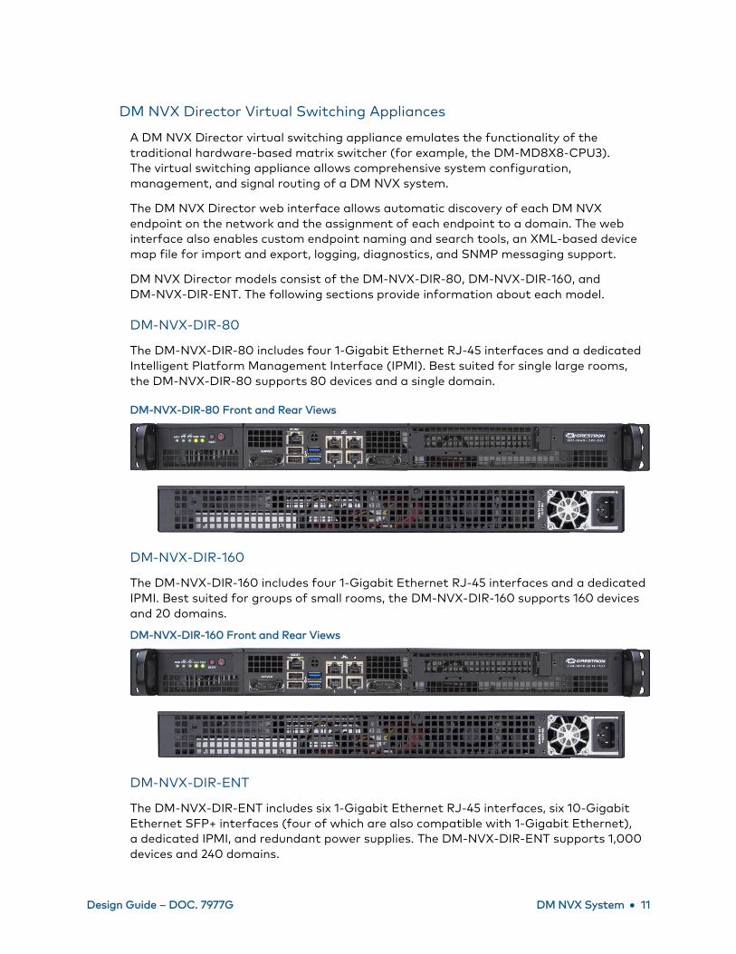
DM-NVX-DIR-80
The DM-NVX-DIR-80 includes four 1-Gigabit Ethernet RJ-45 interfaces and a dedicated
Intelligent Platform Management Interface (IPMI). Best suited for single large rooms,
the DM-NVX-DIR-80 supports 80 devices and a single domain.
DM-NVX-DIR-80 Front and Rear Views
DM-NVX-DIR-160
The DM-NVX-DIR-160 includes four 1-Gigabit Ethernet RJ-45 interfaces and a dedicated
IPMI. Best suited for groups of small rooms, the DM-NVX-DIR-160 supports 160 devices
and 20 domains.
DM-NVX-DIR-160 Front and Rear Views
DM-NVX-DIR-ENT
The DM-NVX-DIR-ENT includes six 1-Gigabit Ethernet RJ-45 interfaces, six 10-Gigabit
Ethernet SFP+ interfaces (four of which are also compatible with 1-Gigabit Ethernet),
a dedicated IPMI, and redundant power supplies. The DM-NVX-DIR-ENT supports 1,000
devices and 240 domains.

12 • DM NVX System Design Guide – DOC. 7977G
DM-NVX-DIR-ENT Front and Rear Views
DM NVX Director Virtual Switching Appliance Comparison
The following table summarizes the major differences among the DM NVX Director
virtual switching appliances.
DM NVX Director Virtual Switching Appliances
DM-NVX-DIR-80 4 1 80
DM-NVX-DIR-160 4 20 160
DM-NVX-DIR-ENT 12 240 1,000
SFP-1G and SFP-10G Transceiver Modules
Crestron SFP-1G and SFP-10G transceiver modules provide fiber connectivity, which
offers greater transmission distances than traditional copper. SFP-1G modules can be
used with the DM NVX endpoints and DM-NVX-DIR-ENT. SFP-10G modules can be
used with the DM-NVX-DIR-ENT only. The following sections provide information about
the modules.
SFP-1G Modules
Available SFP-1G modules consist of the following:
• SFP-1G-SX: 850 nm multimode fiber connections up to 550 m (1800 ft) over
LC-terminated OM3 or OM4 fiber
• SFP-1G-LX: 1310 nm single-mode fiber connections up to 10 km (6.2 mi) using
LC-terminated G.652 fiber
• SFP-1G-BX-U: 1310 nm/1490 nm single-mode fiber uplink connections up to
10 km (6.2 mi) using LC-terminated G.652 fiber
• SFP-1G-BX-D: 1310 nm/1490 nm single-mode fiber downlink connections up to
10 km (6.2 mi) using LC-terminated G.652 fiber
SFP-1G Modules

Design Guide – DOC. 7977G DM NVX System • 13
For each endpoint and for the DM-NVX-DIR-ENT, the connectivity options and the
distance requirements determine the appropriate module that is to be used.
SFP-10G Modules
Available SFP-10G modules for the DM-NVX-DIR-ENT consist of the following:
• SFP-10G-SR: 850 nm multimode fiber connections up to 300 m (1000 ft) over
LC-terminated OM3 and up to 400 m (1300 ft) over LC-terminated OM4 fiber
• SFP-10G-BX-U: 1270 nm/1330 nm single-mode fiber connections up to
10 km (6.2 mi) using LC-terminated G.652 fiber
• SFP-10G-BX-D: 1330 nm/1270 nm single-mode fiber connections up to 10 km
(6.2 mi) using LC-terminated G.652 fiber
For the DM-NVX-DIR-ENT, the connectivity options and the distance requirements
determine the appropriate module that is to be used.
Endpoint Bandwidth Design and Management
A single DM NVX network link can carry the following data streams:
• Primary Audio/Video Stream: HDMI® or analog audio and HDMI video that are
encoded and sent to the network for decoding by a remote endpoint
• Secondary Audio Stream: Audio stream that is encoded and sent for decoding
independently of the primary audio/video stream
• USB Device and Host Traffic: USB data from the DM NVX device or host port
(available on DM-NVX-35x and DM-NVX-35xC devices only)
• Other Ethernet Traffic: Control data as well as data from DM NVX network ports
connected to third-party devices such as displays or cameras. Ethernet traffic
also includes network protocol traffic such as DHCP, DNS, and RADIUS for
802.1X.
Default video bit rate settings are sufficient for most installations but can be adjusted
to accommodate unique situations. Ethernet bandwidth ratings are bidirectional;
therefore, full USB 2.0 bandwidth is supported for DM-NVX-35x and DM-NVX-35xC
devices. In an installation in which video from a PC is encoded and sent to a decoder at a
display, and a high-bandwidth USB camera at the display sends USB video back to the
PC, no bandwidth issues exist. Although the sum of all traffic may exceed 1 Gbps in this
scenario, the traffic in each direction is less than 1 Gbps.

14 • DM NVX System Design Guide – DOC. 7977G
Example of Bidirectional Bandwidth under 1 Gbps
An encoder that attempts to send 900 Mbps video and 480 Mbps USB 2.0 traffic
exceeds the maximum network link bandwidth of 1 Gbps and, as a result, the link will fail.
Example of Failed Link with Required Bandwidth Greater than 1 Gbps
DM-NVX-35x and DM-NVX-35xC devices support Layer 2 and Layer 3 transport of
USB 2.0 data. For Layer 2 transport, one local connection to the device port of a
DM NVX device supports up to seven remote host port connections simultaneously.
When multiple remote connections are required, a hub must be used to connect to each
remote host port. To prevent excessive USB traffic for Layer 2 support of multiple
remote connections, only one high-bandwidth USB device can be used regardless of the
number of remote connections.
For USB 2.0 Layer 3 transport, one local connection supports only one remote
connection. Layer 3 supports USB 2.0 transport of data across VLANs.
The OPS port of the DM-NVX-D80-IOAV includes USB 2.0 host port functionality,
enabling the DM-NVX-D80-IOAV to function as a remote extender. For OPS-supported
displays with touch screen capability, the OPS port of the DM-NVX-D80-IOAV routes
USB signals from the touch screen to a computer.
Design Guide – DOC. 7977G DM NVX System • 15
Endpoint Design Considerations
To implement an optimal configuration for a DM NVX system, consider the following
factors for each endpoint:
• If rack-mount sources are required or if a high density of endpoints must exist
in close proximity to each other, use card-based endpoints.
• If simultaneous stereo downmixing alongside multichannel audio output is
required, use the DM-NVX-351 or DM-NVX-351C.
• If Dante® or AES67 audio networking is required, use the DM-NVX-352 or
DM-NVX-352C.
• For an encoder-only endpoint and when video switching is not required, use the
DM-NVX-E30 or DM-NVX-E30C.
• For a decoder-only endpoint without video scaling, use the DM-NVX-D30,
DM-NVX-D30C, or DM-NVX-D80-IOAV. The DM-NVX-D80-IOAV must be used
with an OPS-supported display.
• Follow the guidelines for cable types as specified in TIA/EIA-568 for choosing and
certifying cables in a DM NVX installation.
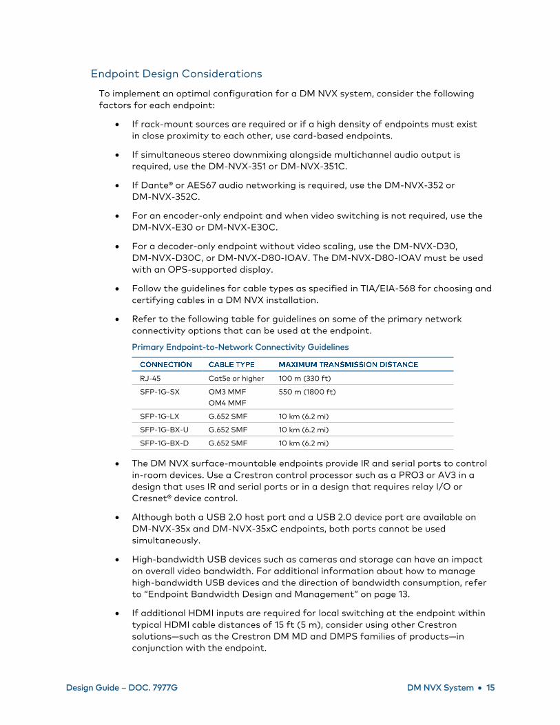
• Refer to the following table for guidelines on some of the primary network
connectivity options that can be used at the endpoint.
Primary Endpoint-to-Network Connectivity Guidelines
RJ-45 Cat5e or higher 100 m (330 ft)
SFP-1G-SX OM3 MMF
OM4 MMF
550 m (1800 ft)
SFP-1G-LX G.652 SMF 10 km (6.2 mi)
SFP-1G-BX-U G.652 SMF 10 km (6.2 mi)
SFP-1G-BX-D G.652 SMF 10 km (6.2 mi)
• The DM NVX surface-mountable endpoints provide IR and serial ports to control
in-room devices. Use a Crestron control processor such as a PRO3 or AV3 in a
design that uses IR and serial ports or in a design that requires relay I/O or
Cresnet® device control.
• Although both a USB 2.0 host port and a USB 2.0 device port are available on
DM-NVX-35x and DM-NVX-35xC endpoints, both ports cannot be used
simultaneously.
• High-bandwidth USB devices such as cameras and storage can have an impact
on overall video bandwidth. For additional information about how to manage
high-bandwidth USB devices and the direction of bandwidth consumption, refer
to “Endpoint Bandwidth Design and Management” on page 13.
• If additional HDMI inputs are required for local switching at the endpoint within
typical HDMI cable distances of 15 ft (5 m), consider using other Crestron
solutions—such as the Crestron DM MD and DMPS families of products—in
conjunction with the endpoint.

16 • DM NVX System Design Guide – DOC. 7977G
• In many DM NVX installations, configure specific control surfaces (such as
Crestron touch screens) and additional switch options (such as local HDMI
switches) at endpoints.
Network Design
DM NVX systems require a designed and provisioned Ethernet network to function
correctly. Be sure to gather requirements and documentation, coordinate with IT staff,
and complete network design prior to site work.
Minimum Network Requirements
Minimum network requirements must be met for a successful installation. Minimum
requirements consist of the following:
• Network switch:
- 1-Gigabit port for every connected DM NVX endpoint
- Nonblocking backplane
- Layer 3
- IGMPv2 implementation
• Network switch settings:
- IGMPv2 snooping enabled
- IGMPv2 querier enabled
- Fast-leave enabled (also known as immediate-leave)
• Inter-switch uplinks (if required):
- The uplinks must have sufficient bandwidth for all encoders and decoders
connected to the network switch. Allocate 1 Gigabit per encoder or decoder
connected to the switch.
- Uplinks must be configured properly to support multicast traffic.
Network Design Overview
DM NVX networks must be designed to isolate traffic on network segments specifically
architected for DM NVX devices. This can be accomplished by using separate
infrastructure, Virtual Local Area Networks (VLANs), or Multi-Protocol Label Switching
(MPLS). DM NVX network segments carry DM NVX multicast streams, DM NVX control,
and ancillary traffic.
The location of other Crestron network devices relative to network infrastructure
must be determined. A decision must be made as to whether the devices are to coexist
on the same network segment as the DM NVX segment or on another segment that
has traversal capabilities to the DM NVX segment but is not multicast enabled.
Networked AV devices other than DM NVX devices can be placed on the DM NVX
network segment if their bandwidth requirements are relative to the DM NVX endpoint
bandwidth requirements.

Design Guide – DOC. 7977G DM NVX System • 17
A DM NVX device can have several addresses:
• An IP address is required for control of the device and access to the web
configuration interface and console. For the DM-NVX-352 and DM-NVX-352C, an
IP address for the Dante module is also required.
• Multicast addresses are required for multicast streams:
- One multicast address is required for the primary multicast stream of audio
and video.
- (DM-NVX-35x[C] Series devices only) Another multicast address is required
for the secondary audio multicast stream.
- (DM-NVX-352 and DM-NVX-352C only) A Dante multicast address is also
required if a Dante multicast stream is used.
During endpoint configuration, the primary multicast address must be set
manually to an even-numbered IP address. The secondary audio multicast stream
address can be automatically assigned to a value of one higher than the primary
IP multicast stream address or can be manually set to the desired multicast
address.
A Dante multicast address is automatically assigned. The address must be unique
and must not match a DM NVX multicast address. If the Dante multicast
address does match a DM NVX multicast address, the DM NVX multicast address
must be changed. (For information about Dante networking, refer to the
information provided on the Audinate® website at www.audinate.com.)
The DM NVX network segment must receive network services, including DNS, DHCP,
Active Directory, and RADIUS services. Coordinate with IT staff to provide access to
these services and to create the proper traversal rules to the DM NVX network segment.
Network Segmentation along Logical Boundaries
AV control switch
DM NVX
network
Streaming
network
Enterprise network
(for example, DNS or DHCP)
Guest wireless Enterprise wireless
AirMedia®
presentation gatewayAudio-over-IP
network
LAN

18 • DM NVX System Design Guide – DOC. 7977G
Consideration must be given to blocking at both the switch level and the network
design level. DM NVX network switches must have enough switch fabric bandwidth to
support full nonblocking bidirectional gigabit bandwidth on all ports simultaneously.
This is a common feature in enterprise-grade gigabit network switches, but it should
not be assumed that a switch is nonblocking or is configured as nonblocking.
Due to system size or physical layout, most DM NVX installations require multiple
network switches. The network switches must connect to each other via a
high-bandwidth uplink port. For network design purposes, assume that each DM NVX
link consumes the full gigabit of link bandwidth.
Consider the example of a standard 48-port Gigabit Ethernet switch with one
40-gigabit uplink (or four 10-gigabit uplinks). Since each DM NVX endpoint consumes
1 gigabit of bandwidth, this switch can support up to 40 DM NVX devices in a
nonblocking way. If more devices are connected, the uplink becomes a bottleneck,
introducing the potential for difficult-to-diagnose blocking problems.
Network Topologies
Connect devices such as control processors, touch screens, servers, personal computing
devices, and DM NVX endpoints directly to network switches. In a large network with
multiple layers of switch hierarchy, situate these devices at the network’s edge.
The network edge switches are often connected via uplinks to other switches and
routers. This aggregates traffic from the network edge and forms the network’s core.
The relationships between network switches and their interconnection to each other
define the network’s topology.
The following general rules apply for sizing network switches in terms of switch fabric
nonblocking bandwidth:
• The network core must support a nonblocking bandwidth and port speed equal to
1 gigabit multiplied by the lesser of the total number of anticipated encoder
endpoints or the total number of anticipated decoder endpoints, plus the number
of USB extenders.
• The network edge must support a nonblocking bandwidth and uplink speed equal
to 1 gigabit multiplied by the greater of the total number of anticipated encoder
endpoints or the total number of anticipated decoder endpoints, plus the number
of discrete USB extenders.
Star
The default recommended network topology is a star. Using a fully nonblocking switch,
the star topology allows any combination of one or more endpoints to connect to any
other combination of endpoints. It also easily allows the network to grow beyond a single
switch if the uplink in the switch supports the maximum specified bandwidth.
For small DM NVX systems that employ only one network switch, use a nonblocking
switch to prevent a bottleneck. Star topologies can accommodate very large DM NVX
installations by using large modular switch frames.

Design Guide – DOC. 7977G DM NVX System • 19
Star Network Using a Nonblocking Switch
Tree
A tree network is a combination of more than one star network existing on a
core-switching infrastructure. The tree network allows failure in one part of the attached
star networks without widely affecting the other star networks. Configure the core
network, which is the larger network switch, for redundancy and scalability.
Tree Topology Using Nonblocking Switches on a Core Network
Daisy Chain
Daisy chaining is appropriate for specific deployment applications such as video walls or
jury boxes in which all displays receive the same video source as the first DM NVX
endpoint in the chain.
For video wall applications and any other application in which displays are near each
other and share the same source, up to 16 endpoints can be daisy chained together.
Larger video walls can be divided into individual daisy chains that each contain up to
16 endpoints.
For applications such as information signage in which more than one display is viewable
concurrently without being dependent on the viewing of another display in the daisy
chain, up to 64 endpoints can be daisy chained together.

20 • DM NVX System Design Guide – DOC. 7977G
Daisy Chain Network Configuration for 3 x 3 Video Wall
Daisy Chain Network Configuration for 12-Person Jury Box
Due to limited bandwidth for audio and video, a USB host or device on a daisy chained
endpoint is not recommended. For maximum flexibility and the ability to reconfigure
video walls with multiple sources, connect DM NVX endpoints directly to switches rather
than daisy chain the endpoints.
Other Topologies and Network Functionality
Other valid deployment topologies for DM NVX networks are ring and mesh. These
deployments require project-specific discovery and configuration of the network switch.
For projects using advanced topologies for deployments, a networking professional must
be involved early in the network design process.

Design Guide – DOC. 7977G DM NVX System • 21
Network Multicast Functionality
DM NVX networks rely on multicast functionality to send and receive video—even in the
simplest case of a single encoder endpoint and a single decoder endpoint. Internet Group
Management Protocol (IGMP) multicast in the Ethernet context replaces a fixed
switching architecture in AV distribution.
Segregation of DM NVX traffic by using a VLAN or MPLS is usually the first step in
enabling multicast. A VLAN or MPLS ensures that DM NVX traffic stays on the DM NVX
network and does not route to other network segments and interfere with their
operation. A VLAN or MPLS also ensures that traffic from other network segments does
not interfere with DM NVX operation. Within that segment, all ports can be flooded by
IGMP traffic regardless of whether that traffic was intended to be sent or received by a
network device at any time. This will result in interference with network operation and
can be a means of implementing a denial-of-service attack on a network if done
maliciously.
To ensure that only traffic between intended multicast senders and multicast receivers
appears at a given port, IGMP snooping must be enabled. IGMP snooping refers to the
ability of the network switch to limit multicast traffic only to ports between intended
senders and receivers. The DM NVX network supports both versions of IGMP snooping:
IGMPv2 and IGMPv3.
In order for the network switch to know where route limiting is implemented in the
network for multicast traffic, an IGMP querier must be enabled. In most instances, a
single network switch is selected by address to act as the IGMP querier; however, if
multiple switches are configured as queriers, the switch with the lowest numerical IP
address on the network is typically the default. The default leave time for the querier
(typically about 125 seconds) is sufficient for a DM NVX network.
Protocol Independent Multicast (PIM)
Protocol Independent Multicast (PIM) is a family of multicast routing protocols for IP
networks. PIM offers one-to-many and many-to-many distribution of data. PIM modes
include PIM Sparse Mode (PIM-SM), PIM Dense Mode (PIM-DM), and PM Source-Specific
Multicast Mode (PIM-SSM). PIM-SM must be used for large DM NVX networks.
PIM-SM finds the shortest trees per path from a multicast source to multicast receivers
on a network and is more scalable than PIM-DM or PIM-SSM. PIM-SM also prevents
edge-to-switch link saturation and network loops in multicast traffic routing.
Enabling network Quality of Service (QoS) helps prioritize DM NVX traffic over other
traffic at both the source and the destination. The highest priority on IGMP multicast
traffic must be enabled. An example of enabling network QoS is as follows:
1. Enable 802.1Q VLAN tagging support in the network switch.
2. Enable and assign an 802.1P priority (for example, 5, 6, or 7) to DM NVX
addresses and ports or IGMP protocol traffic.

22 • DM NVX System Design Guide – DOC. 7977G
3. For other traffic, such as HTTP for web services or SSH for console access, assign
lower priority numbers (for example, 0 to 4) based on their addresses, ports, or
protocols.
4. For successful QoS operation, ensure that all traffic types are included in the
QoS setup.
NOTE: In addition to 802.1Q and 802.1P mentioned on the preceding page, other QoS
protocols exist and are dependent on the switch vendor. The protocols are configured
similar to the 802.1Q and 802.1P examples on the preceding page.
PIM Multicast Routing Protocol for an IP Network
Network Security
Security requires the support of particular capabilities within all devices on the network.
DM NVX networks employ the following security features:
• 802.1X authentication is used to ensure that devices on the network have been
authorized by the network administration team. Unauthorized devices are
prevented from being added to the network and from having access to sensitive
content.
• Active Directory services for endpoint administration can be used to ensure that
administrative privileges for DM NVX devices can be centrally managed, granted,
and revoked when necessary.
• DM NVX endpoints use Advanced Encryption Standard (AES) block cipher with
Public Key Infrastructure (PKI) for stream encryption to protect content from
unauthorized access as it crosses the network.

Design Guide – DOC. 7977G DM NVX System • 23
• SSL-based secure Cresnet over IP (CIP) for DM NVX control ensures that control
processors and DM NVX devices communicate with the intended party device and
that any unauthorized device on the network cannot monitor commands
and status.
• SSH-based command line console access for device configuration and status
protects the device console from access by unauthorized users.
SSL-based Cresnet over IP and SSH-based command line console access are
automatically configured within DM NVX devices and support software. The designer
should focus on 802.1X and Active Directory services within the design.
For additional information about deploying security with Crestron products, refer to the
IP Considerations Guidelines for the IT Professional Design Guide (Doc. 4579) at
www.crestron.com/manuals and to Answer ID 5571 in the Online Help section of the
Crestron website (www.crestron.com/onlinehelp).
Network Design Considerations
Consider and apply the following network design best practices:
• Use nonblocking Layer 3 switches with port-based QoS such as 802.1P with
802.1Q at all stages of the design. Use sufficient switch bandwidth and port
speeds. Less expensive switches cause loss of capability in the network.
• Choose switches with sufficient bandwidth at each segment—from edge to
core—to accommodate a nonblocking architecture for DM NVX endpoints and
any additional needs.
• Choose an appropriate network topology. Consider the network, including basic
functionality and redundancy, and whether video walls or repetitive display
signage is necessary. When planning a topology for the network, ensure that
network IT staff and network architects are involved in the decisions.
• Enable an IGMP querier on at least one switch in the DM NVX network. The IGMP
querier ensures that all switches know which multicast transmitters and receivers
are connected to which switches in the network. Enabling an IGMP querier on
multiple switches causes the switch with the lowest value of IP source address to
take priority and act as the querier.
• Consult the network switch manufacturer’s documentation to ensure that the
uplinks are properly configured to support multicast traffic.
• Use switches that support 802.1X for endpoint authentication by implementing
802.1X endpoint authentication through TLS or MS-CHAP v2. Only authorized
endpoints can communicate with the network.
• Ensure that VLANs or MPLS are implemented correctly. Leveraging existing
switch infrastructure with VLANs or MPLS can cause conflicts with network
provisioning needs. If a dedicated DM NVX network is not going to be used,
VLANs must be implemented correctly with their own IP subnet, and MPLS
networks must be configured correctly.

24 • DM NVX System Design Guide – DOC. 7977G
• Account for even-numbered DM NVX primary stream multicast address
assignments since both primary and secondary multicast streams are possible.
The assignment of multicast IP addresses for primary streams should be even
numbered to allow the secondary stream to be assigned to the odd-numbered IP
address, which is one higher than the primary stream’s IP address. For multicast
IP address assignment, refer to the guidelines in IETF RFC 3171.
• Use the Active Directory service for administration security:
- Create an Active Directory group responsible for device administration.
- Add device administrators to the group.
- Add the group to the DM NVX device on the Device page of the
web interface.
Use of the Active Directory service with DM NVX endpoint logins allows for easy,
seamless, and better controlled access from a central directory authority with
fewer risks.
• Use a DHCP server with link-layer filtering, and configure the IP addresses of
endpoints using DHCP rather than static IP addresses. Using a DHCP server with
short lease times, MAC address filtering, and sufficient address space for future
needs makes network management easier.
• Enable IGMPv2 (DM NVX default) or IGMPv3 multicast snooping on all switches
in the DM NVX network. This is a requirement for all designs in order to enable
multicast delivery to multiple endpoints. Without IGMP snooping enabled,
switches that receive a multicast stream will transmit that stream to all ports
simultaneously and saturate all network links.
• Use the Rapid Spanning Tree Protocol (RSTP) on the network to ensure that
network loops are discoverable and to prevent deployment issues. Network
management should account for RSTP discovery downtime when the network
changes.
• Use and plan for DM NVX Director management of endpoints.
• Use daisy chaining to connect video wall endpoints or repeated displays.
For video walls or endpoints that receive the same source from a single
transmitter to feed multiple identical displays or in a video wall using a single
source, it is simpler and less expensive to daisy chain the network.
• Disable IGMP proxy functionality on Crestron control processors with routers to
ensure that DM NVX multicast traffic does not interfere with the control
processor. The CP3N, Pro3, and AV3 control processors as well as DMPS3
presentation systems should have IGMP proxy functionality disabled when
connected to the DM NVX network.
• Account for high-bandwidth external USB devices that are to be connected
to DM NVX devices. Ensure that the bandwidth is accounted for as a separate
1-gigabit link since USB 2.0 bandwidth can consume 480 Mbps of the
1-gigabit link.

Design Guide – DOC. 7977G DM NVX System • 25
• Ensure that multicast IP addresses do not share the multicast MAC addresses.
Sharing MAC addresses can cause network collisions and prevent normal
operation of the DM NVX network.
• For Dante and AES67 audio networking with DM-NVX-352 and DM-NVX-352C
devices, additional network considerations may need to be addressed. For
Ethernet switch guidelines, refer to the information provided on the Audinate
website at www.audinate.com/networks-and-switches.
System Installation
The installation phase should ensure that the interaction among designer, installer,
programmer, and end user is considered in all installation decisions.
Endpoint Installation
Each DM NVX endpoint has unique installation requirements that depend on the
following:
• Copper or fiber network connectivity of the endpoint
• Surface-mountable or card-based endpoint
• Configuration of a combined encoder/decoder endpoint as a transmitter or a
receiver or whether the endpoint is to switch dynamically between modes
• Additional local HDMI inputs that require configuration
• Use of source autoswitching or external switching control
• Additional audio sources that require encoding
• USB device or host functionality
• Whether the endpoint is part of a video wall or goes to multiple identical displays
• Requirement for serial or IR control or both
A Crestron touch screen can be linked through a spare LAN port on an endpoint.
An audio input/output port can be repurposed to be a balanced line input for external
analog audio input or for line output to a speaker system at the endpoint.
The endpoint features and attached devices can be configured through programming or
through the web interface.
Depending on the location of the control processor, serial and IR control of endpoint
devices may be routed directly from that control processor. Access to HDMI and USB
inputs and outputs can be provided through Crestron HDMI breakout devices for
tabletops and walls.

26 • DM NVX System Design Guide – DOC. 7977G
Surface-mountable endpoints can be mounted in any orientation as required. Typical
locations for surface-mountable endpoints include inside closets and drop ceilings,
underneath tables, and in podiums. The specific location is determined by the
following factors:
• Length of HDMI and USB cable runs
• Location of display and audio devices, network connectivity, power for the device,
and physical security requirements
Serial and IR connectivity can be run at longer lengths and are typically not drivers of the
endpoint mounting location.
For card-based endpoints, the DMF-CI-8 card chassis is placed in a closet or locked rack
near the source and display devices. (To ensure that the environmental conditions in the
rack meet the specifications outlined, refer to the DMF-CI-8 product page on the
Crestron website.)
Serial and IR interfaces are not provided by card-based endpoints. The functionality
must be provided by other means, such as through a local Crestron control processor on
the DM NVX network.
For a maintenance-free installation, follow these guidelines:
• While taking into account cable distances, plan the optimum location for the
surface-mountable or card-based endpoint—especially when distance-limited
HDMI cables are involved.
• Avoid direct access to the endpoint by the end users. End users can induce
failures or create a security risk due to unauthorized network access. Ensure that
HDMI cables and wall plates are routed away from the endpoint appropriately.
• Use Category 2 certified HDMI cables to meet the minimum HDMI specifications
at 4K or 1080p and to prevent problems such as degradation or loss of video
or audio.
• Use properly terminated network cables. Network cabling must be either of the
following:
- Fiber that is terminated with a clean LC connector
- Shielded or unshielded Cat 5e or higher copper cable that is terminated with
an RJ-45 connector
• Observe the minimum bend radiuses and pull forces of cables to maintain cable
integrity and prevent failures.
• Use plenum-rated cables in plenum spaces. Cables such as Crestron
DigitalMedia™ plenum-rated cables are suitable. Fire-rated conduit for any fiber
or copper cabling used in plenum spaces is also suitable.
• Practice good cable dressing—especially for card-based endpoints in racks.
• Manage EDID and HDCP proactively. For additional information, refer to the
Crestron DigitalMedia System Design Guide (Doc. 4546) at
www.crestron.com/manuals.
Design Guide – DOC. 7977G DM NVX System • 27
• HDR and deep color sources may not display correctly on endpoints with
non-HDR or non-deep color displays. Ensure that the capabilities of the sources
are matched to the capabilities of the displays.
• Use descriptive names for endpoints either through the DM NVX web interface or
by replacing the default name in the Crestron Toolbox™ software. Do not rely on
the default name or the Crestron IP ID.
• Physically secure the endpoint to a fixed point or rack to prevent movement
over time. Secure all mounting points and mounting hardware for surface-
mountable endpoints, card chassis, and card-based endpoints.
• Leverage use of the DM NVX Director server for endpoint configuration.
The presence of a DM NVX Director server makes it easy to configure and control
multiple DM NVX endpoints on the network.
• Thoroughly document the installation of endpoints—including drawings, lists, and
descriptions—in order to provide detailed information for those who are to
maintain or upgrade the DM NVX network.
Network Installation
The installation of a DM NVX network varies greatly depending on a number of factors,
including the following:
• Whether existing network infrastructure such as switches and cabling are to
be reused
• Location of closets, racks, Intermediate Distribution Frames (IDFs), and Main
Distribution Frame/Combined Distribution Frame (MDF/CDF) relative to the
endpoints
For optimal installation and maintenance of the DM NVX network, follow these best
practices:
• Use or repurpose existing infrastructure in DM NVX network installation cases.
• Use physical security for the network. Secure all network locations (MDF/CDF
and IDF down to individual closets) from unauthorized access.
• Disable any unused ports on the network switches.
• Use a structured cabling approach such as those described in the TIA/EIA-568
standard. Include keystones in jacks and patch panels, shielded or unshielded
solid copper conductor cable not exceeding 295 ft (90 m), and patch cables
not exceeding 33 ft (10 m) to connect between patch panels. Use cable testers
to verify the integrity of the installation and capacity for future expansion
and backup.
• Use Crestron switch configuration files.
• Configure the routing of external servers. If nondedicated DHCP, RADIUS,
Active Directory, or other servers are used, ensure that the servers access the
DM NVX network.
• Thoroughly document all DM NVX network hardware and configurations.

28 • DM NVX System Design Guide – DOC. 7977G
Crestron Service Provider Handoff
Consult the Crestron Service Providers (CSPs) once the DM NVX network and endpoints
are installed and interconnected. Typical activities of a CSP in a DM NVX installation
may include the following:
• Writing appropriate control programs for controllers on the network
• Programming appropriate serial and IR control for endpoint devices
• Configuring external analog and digital audio source input and output
• Configuring video walls
• Designing button and UI features for control surfaces such as touch screens
and switches
• Managing EDID for endpoint devices
As CSPs implement and deploy the program, installers and designers should test and
review the functionality. The programmer must document the program functionality to
avoid future issues.

Design Guide – DOC. 7977G DM NVX System • 29
Case Studies
This section provides the following case studies using DM NVX products:
• Case Study 1: Community College 4K AV Distribution Network
• Case Study 2: 4K Residential AV Distribution Network
• Case Study 3: 4K AV Distribution over Fiber
Case Study 1: Community College 4K AV Distribution Network
A client wants to distribute ten 4K HDMI video sources located in an IDF closet to
50 classrooms at a community college. More classrooms and 10 video sources are to be
added in the future. The existing network cabling infrastructure is to be used—only the
network hardware is required. External sound bars must be used for audio output at
the displays.
Solution:
• The Crestron design is based on the use of DM-NVX-350 encoders and decoders
and the DM-NVX-DIR-160:
- Ten DM-NVX-350 encoders with video source connections are located in the
IDF closet.
- Each of the 50 classrooms has a DM-NVX-350 decoder that connects to a
display. The DM-NVX-350 decoders feed video to the displays and provide
serial control of the displays.
- A DM-NVX-DIR-160 is used to set up, control, and monitor the DM NVX
system. The DM-NVX-DIR-160 also provides the capability to add classrooms
and ten video sources in the future.
• Using a star network topology, any source can be routed to any destination.
• The system can be controlled via the Crestron App for mobile and tablet devices.
• A Crestron CP3N control processor is installed in the MDF closet to provide
centralized control for the entire system. Since no additional external control
from the control processor is necessary, the processor connects directly to the
network switch.
• A nonblocking network switch is used. The network switch has enough ports for
10 video source endpoints and 50 video display endpoints. In addition, the
network switch can be reconfigured to support an additional 10 sources.

30 • DM NVX System Design Guide – DOC. 7977G
Case Study 1 Solution Diagram

Design Guide – DOC. 7977G DM NVX System • 31
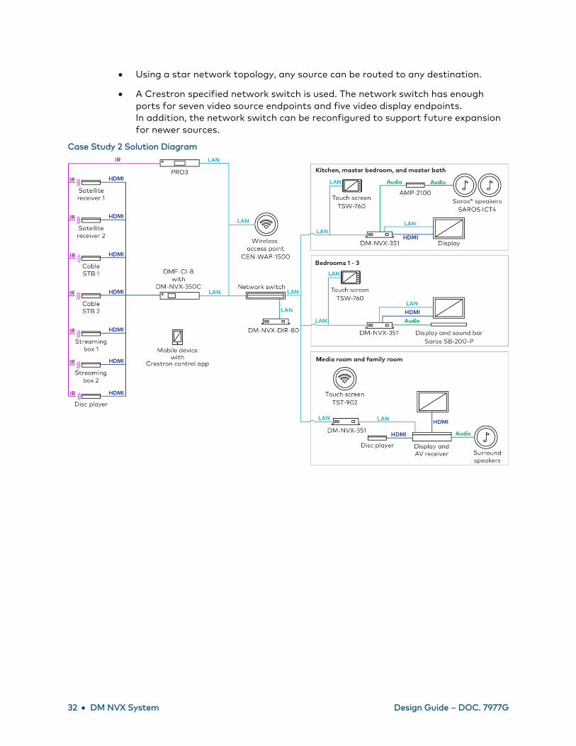
Case Study 2: 4K Residential AV Distribution Network
A privately owned home needs a retrofit 4K video distribution system. Sources are
located in the basement rack room and are distributed to TV and surround sound
receiver locations throughout the house. The desired system requires two satellite
receivers, two cable set-top boxes (STBs), two streaming boxes, and one disc player.
The media room and family living room require surround sound systems with a local
4K HDR Blu-ray™ player and 4K HDR displays. All other rooms require external speakers
with stereo output. The kitchen, master bedroom, and master bathroom require
in-ceiling speakers. Touch screens are the desired control surfaces. The media room and
family living room are not able to have wire runs for the touch screens—only local power
is available. Existing network infrastructure can be reused.
Solution:
• The Crestron design is based on the use of DM-NVX-350C cards as encoders,
DM-NVX-351 surface-mountable endpoints as decoders, and the
DM-NVX-DIR-80:
- Seven DM-NVX-350C cards are installed in a DMF-CI-8 chassis in the
basement rack. Each of the seven video sources in the basement rack room
connects to a DM-NVX-350C encoder.
- The kitchen, master bedroom, and master bathroom each have a
DM-NVX-351 decoder that connects to a display and provides audio
downmixing. The stereo line audio output of a DM-NVX-351 connects to a
two-channel amplifier with two Crestron Saros® IC4T in-ceiling speakers per
room.
- Bedrooms 1, 2, and 3 each have a DM-NVX-351 decoder that connects to a
display and provides audio downmixing. The stereo line audio output of a
DM-NVX-351 connects to a Crestron Saros SB-200-P sound bar.
- The media room and family room each include a surround sound system that
connects to a DM-NVX-351. The HDMI OUT from a surround sound system
connects to a display. In-room speakers connect to the surround sound
system.
- A DM-NVX-DIR-80 is used to set up, control, and monitor the DM NVX
system.
• The kitchen and three bedrooms each use a TSW-760 touch screen. The rooms
can also be controlled using the Crestron App for mobile and tablet devices.
• Due to a cable routing constraint, the media room and family room each have a
TST-902 wireless touch screen for control. The rooms can also be controlled using
the Crestron App for mobile and tablet devices.
• A Crestron PRO3 control processor with expansion cards controls the entire
system by providing IR and other peripheral control.
32 • DM NVX System Design Guide – DOC. 7977G
• Using a star network topology, any source can be routed to any destination.
• A Crestron specified network switch is used. The network switch has enough
ports for seven video source endpoints and five video display endpoints.
In addition, the network switch can be reconfigured to support future expansion
for newer sources.
Case Study 2 Solution Diagram

Design Guide – DOC. 7977G DM NVX System • 33
Case Study 3: 4K AV Distribution over Fiber
A client requires 4K AV distribution of 563 sources that are co-located at the MDF for
10 different locations on a campus up to 0.8 km (0.5 mi) from the MDF. Each location
contains 18 separate displays and four 2 x 2 video walls across multiple rooms. The client
needs to use a fiber-optic network for all video distribution. All device logins must be tied
to the campus Active Directory, DHCP, and 802.1X services for policy reasons.
Core redundancy is required to minimize campus-wide disruptions. Users must be
able to switch between sources at any display independently.
Solution:
• The Crestron design is based on the use of DM-NVX-350 endpoints as
encoders and decoders, a fiber-optic network across a large MDF, and
the DM-NVX-DIR-ENT:
- Endpoints consist of 563 DM-NVX-350 encoders at the MDF,
180 DM-NVX-350 decoders for the rooms, and 40 DM-NVX-350 decoders for
the 2 x 2 video walls in the 10 locations (4 decoders for each location).
- Single-mode 1310 nm/1490 nm fiber is used. The network switches are
configured using SFP 1G BX downlink modules, and the DM-NVX-350
encoders and decoders use SFP-1G-BX-U uplink modules for fiber
connections.
- A DM-NVX-DIR-ENT allows fiber to be used for the DM NVX system.
The DM-NVX-DIR-ENT is used to set up, control, and monitor the
DM NVX system.
• A Crestron PRO3 control processor is used in each of the 10 locations.
• A TSW-760 touch screen is used in each of the 18 rooms across 10 locations,
totaling 180 touch screens. In addition, a TSW-760 touch screen is used for each
video wall room in the 10 locations, totaling 10 touch screens that provide user
control of the entire system. Each touch screen is powered by a Crestron
PWE-4803RU PoE injector.
• A tree architecture requires a minimum core switch bandwidth of 252 Gbps for
563 encoders and 252 (180 + 72) decoders. The existing core switch is capable of
1 Tbps and will be reused and reconfigured for 1 Tbps as required.
• Each of the 10 locations requires 22 DM-NVX-350 decoders to provide a
nonblocking switch with at least 22 free ports.
• The network switches are configured to route the campus RADIUS server for
802.1X, the campus Active Directory server for login authentication at each
endpoint, the campus DNS server for name assignment, and the campus DHCP
server for IP assignment and MAC filtering; similarly, the endpoints are
configured to utilize these services.

34 • DM NVX System Design Guide – DOC. 7977G
• Four of the 22 DM-NVX-350 decoders in each of the 10 locations are daisy
chained to connect the decoders in the video wall rooms. The 3-port switch of the
DM NVX endpoints consists of the following connections:
- SFP-1G-BX-U connection to the edge switch
- RJ-45 connection used in the daisy chain to connect the other video wall
endpoints
- RJ-45 connection to the TSW-760 touch screen for video wall room control
Case Study 3 Solution Diagram

Design Guide – DOC. 7977G DM NVX System • 35
Glossary
802.1P: A network quality of service labeling protocol that assigns a number from zero to
seven to determine network traffic priority; defined in IEEE 802.1P-1998
802.1Q: A network protocol that allows for VLANs and tagging of VLAN traffic and
enables 802.1P to provide quality of service features; defined in IEEE 802.1Q-2014
802.1X: A network control protocol to authenticate devices connected to an Ethernet
network on a port-by-port basis by encapsulating the Extensible Authentication
Protocol; defined in IEEE 802.1X-2010
Active Directory: An application protocol developed for Microsoft® Windows® networks
that authenticates and authorizes users and devices using login mechanisms and also
stores and controls additional information on the network regarding users and resources
Core: The central point of a network from which all network devices and intermediate
infrastructure are normally accessible
Closet: The distribution point for networking infrastructure localized to a floor or group
of rooms
Dynamic Host Configuration Protocol (DHCP): A network protocol that distributes
network parameters such as IP addresses through a server to clients requesting them;
defined in IETF RFC 2131
Domain Name System (DNS): A system of naming computers on a network that have
numerical IP addresses; defined across multiple IETF RFCs starting with IETF RFC 1034
Domain Controller: A server-running domain service such as AD or LDAP
Extensible Authentication Protocol (EAP): A protocol for authentication of point-to-
point network connections using multiple methods including TLS and MS-CHAP v2;
defined in IETF RFC 3748 and IETF RFC 5247
Edge: The endpoint of a network connection that allows end device interconnection with
the network
Extended Display Identification Data (EDID): A data structure usually communicated
over HDMI and DVI interfaces between audio/video sources and displays to identify the
capabilities of the devices on the link; defined in VESA EDID Version 3 and EIA/CEA-861
Intermediate Distribution Frame (IDF): The signal distribution frame that allows
interconnection between the main distribution frame and premises closets
International Electrotechnical Commission (IEC): A nonprofit organization that publishes
standards regarding electrical and electronic standards
Institute for Electrical and Electronics Engineers (IEEE): A nonprofit organization that
publishes electrical and electronics standards particularly for network communication
through the IEEE 802 family of standards
Internet Engineering Task Force (IETF): A standards organization that establishes and
maintains voluntary standards for Internet networking globally

36 • DM NVX System Design Guide – DOC. 7977G
Internet Group Management Protocol (IGMP): A network protocol that allows multicast
traffic to pass over adjacent routers on an IPv4 network; defined in IETF RFC 2236 for v2,
and IETF RFC 3376 and IETF RFC 4604 for v3
Internet Protocol (IP): A communications protocol that relays information across
network boundaries between addresses; defined in IETF RFC 791 for IP version 4
Infrared (IR): A method of providing device control using light waves just beyond the
range of red light
International Standardization Organization (ISO): A nongovernmental organization that
publishes standards on all topics for international use, including audio and video
compression standards; works jointly with the IEC to develop certain standards such as
JPEG 2000
JPEG: An acronym for Joint Picture Experts Group
JPEG 2000: The image compression technology using wavelet-based scaling techniques
to reduce image size without block noise and at high quality; defined in ISO/IEC 15444
Media Access Control (MAC): A 48-bit address in the Ethernet protocol that establishes
the unique physical device in a network that is routed to or from that physical device
Main Distribution Frame (MDF): The signal distribution frame for networking that
connects premises physical plant equipment to outside physical plant equipment
Moving Picture Experts Group (MPEG): A working group of the ISO and IEC that sets
standards for audio and video compression and related technologies
Microsoft Challenge-Handshake Authentication Protocol (MS-CHAP): A network
authentication protocol that is used for network devices by RADIUS servers. MS-CHAP is
defined in IETF RFC 2433 for MS-CHAP v1 and IETF RFC 2759 for MS-CHAP v2.
Multicast: One-to-many data transfer that allows scalable distribution of audio and
video in an efficient manner
Multi-Protocol Label Switching (MPLS): A labeling protocol for network traffic such that
short labels rather than long network headers are used to route traffic appropriately;
defined in IETF RFC 3031
Network Topology: The layout of a network as it would appear visually in a simplified
form
Protocol Independent Multicast–Sparse Mode (PIM-SM): A protocol for routing
multicast traffic such that the routes are optimized and effectively prevent flooding of
uplinks in network infrastructure; defined in IETF RFC 7761
Plenum: Part of a building where heating, ventilation, and air conditioning are provided
Public Key Infrastructure (PKI): A set of procedures and policies for the different roles
required in securely managing digital certificates and the infrastructure used to
exchange both asymmetric encryption keys and symmetric encryption keys
Quality of Service (QoS): A performance improvement feature that prioritizes more
important network traffic over less important traffic in a network switch
Design Guide – DOC. 7977G DM NVX System • 37
Remote Authentication Dial-in User Service (RADIUS): A network protocol that provides
authentication, authorization, and accounting for network devices and users in a secure
way, especially for IEEE 802. 1x protocol, and deployed in a client-server model; defined
in IETF RFC 2865 and IETF RFC 2866
Request For Comments (RFC): A standards publication from the IETF
Real-time Transport Protocol (RTP): A network protocol for the actual delivery of audio
and video streaming media; defined in IETF RFC 3550
Rapid Spanning Tree Protocol (RSTP): A network control protocol for discovering and
accounting for network loops and redundancies; defined in
IEEE 802. 1d-2004
Real-Time Streaming Protocol (RTSP): A network control protocol for streaming media
to establish and control streaming audio and video sessions between endpoints; defined
in IETF RFC 7826
Secure Shell (SSH): A protocol utilizing cryptography that secures network services such
as a command line shell; defined across a number of IETF RFCs beginning with IETF RFC
4250 by the IETF SECSH working group
Structured Cabling: A standard for developing network and cable infrastructure; defined
in TIA/EIA-568
Symmetric Encryption: An algorithm or method of using cryptography such that a single
key is used for both the encryption and decryption of information to be protected
Transport Layer Security (TLS): A protocol implementing cryptographic security on a
computer network; defined in IETF RFC 5246 and IETF RFC 6176
Transport Stream (TS): A media format that encapsulates audio, video, synchronization,
and other information for transport; defined in ISO/IEC 13818-1
Universal Datagram Protocol (UDP): A protocol that transfers information over an IP
network in a connectionless way such that data delivery is not guaranteed yet prevents
the lack of a verified and established connection to prevent data delivery; defined in IETF
RFC 768
Unicast: A one-to-one delivery protocol that is simple but not scalable for multipoint
audio and video distribution
Virtual Local Area Network (VLAN): A nonphysically sequestered broadcast domain or
partition isolated at the data link layer, effectively sequestering switch ports and
network traffic across one or more switches from all other ports and traffic

Crestron Electronics, Inc. Design Guide – DOC. 7977G
15 Volvo Drive, Rockleigh, NJ 07647 (2048398)
Tel: 888.CRESTRON 11/01/19
Fax: 201.767.7576 Specifications are subject to
www.crestron.com change without notice.