dlr-cav2013 robert meyer - pennsylvania state university · full-scale test - installation with dlr...
TRANSCRIPT
Recent Research Activities of DLR Engine Acoustics
German Aerospace Center (DLR)Institute of Propulsion Technology
Engine Acoustics, Berlin
www.DLR.de • Chart 1 > Standard presentation > Jan. 2012
Dr. Robert Meyer
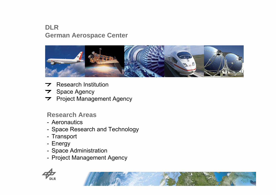
DLRGerman Aerospace Center
Research InstitutionSpace AgencyProject Management Agency
Research Areas- Aeronautics- Space Research and Technology- Transport- Energy- Space Administration- Project Management Agency
Köln
Lampoldshausen
Stuttgart
Oberpfaffenhofen
Braunschweig
Göttingen
Berlin-
Bonn
Trauen
Hamburg Neustrelitz
Weilheim
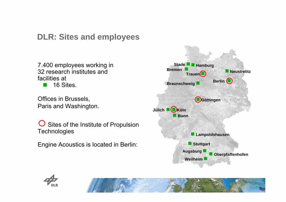
Bremen-7.400 employees working in 32 research institutes and facilities at 16 Sites.
Offices in Brussels, Paris and Washington.
Sites of the Institute of Propulsion Technologies
Engine Acoustics is located in Berlin:
DLR: Sites and employees
Jülich
Stade
Augsburg

DLR Site Cologne (DLR Headquarter)
Employees: 1400Size of site: 550 000 m²Research institutes and facilities:
- Institute of Materials Physics in Space- Institute of Aerospace Medicine- Institute of Propulsion Technology- Institute of Materials Research- Institute of Air Transport and Airport Research- Institute of Solar Research - Institute of Technical Thermodynamics- High-flux-density solar furnace- Simulation- and Software Technology - Quality and Product Assurance- European Astronaut Center- Supersonic and Hypersonic Technologies- European Transonic Wind Tunnel- Microgravity User Support Center (MUSC)- DLR Project Management Agency
> Standard presentation > Jan. 2012www.DLR.de • Chart 4

DLR Site Berlin-Charlottenburg
Employees: 31Scientist: 25Infrastructure: 6+ Students
Research institutes and facilities:Institute of Propulsion Technology
Department of Engine Acoustics
> Standard presentation > Jan. 2012www.DLR.de • Chart 5
Location:Downtown of the Berlin City –Weston Campus of the Technical University of Berlin

Organisation of the Institute of Propulsion Technologie
Institut für AntriebstechnikProf. Dr.-Ing. Reinhard Mönig
Komponenten Querschnittsfunktionen
Fan und VerdichterDr.-Ing. Eberhard Nicke
Fan und VerdichterDr.-Ing. Eberhard Nicke
BrennkammerDr.-Ing. Christoph Hassa
BrennkammerDr.-Ing. Christoph Hassa
TurbineDr.-Ing. Peter-Anton Gieß (komm.)
TurbineDr.-Ing. Peter-Anton Gieß (komm.)
BrennkammertestDipl.-Ing. Christian FleingBrennkammertestDipl.-Ing. Christian Fleing
TriebwerksakustikDr.-Ing. Lars Enghardt (komm.)
TriebwerksakustikDr.-Ing. Lars Enghardt (komm.)
TriebwerksmesstechnikDr.-Ing. Christian Willert
TriebwerksmesstechnikDr.-Ing. Christian Willert
Numerische MethodenDr.-Ing. Dirk Nürnberger
Numerische MethodenDr.-Ing. Dirk Nürnberger
TriebwerkDr.-Ing. Andreas Döpelheuer
TriebwerkDr.-Ing. Andreas Döpelheuer
Zentrum für Verbrennungstechnik
Institute of Propulsion TechniqueProf. Dr.-Ing. Reinhard Mönig
Components General Methods
Fan und VerdichterDr.-Ing. Eberhard Nicke
Fan and CompressorDr.-Ing. Eberhard Nicke
BrennkammerDr.-Ing. Christoph Hassa
CombustorDr.-Ing. Christoph Hassa
TurbineDr.-Ing. Peter-Anton Gieß (komm.)
TurbineProf. Dr.-Ing. Ingo Röhle
BrennkammertestDipl.-Ing. Christian FleingCombustion TestDipl.-Ing. Christian Fleing
TriebwerksakustikDr.-Ing. Lars Enghardt (komm.)
Engine AcousticsProf. Dr. rer. nat. Lars Enghardt
TriebwerksmesstechnikDr.-Ing. Christian Willert
Engine Measurement SystemsDr.-Ing. Christian Willert
Numerische MethodenDr.-Ing. Dirk NürnbergerNumerical Methods
TriebwerkDr.-Ing. Andreas Döpelheuer
EngineDr.-Ing. Andreas Döpelheuer
Center forCombustion Technique
Dr.-Ing. Edmund Kügeler

Engine Noise
Turbine Noise
Combustion Noise
Jet NoiseFan- and Compressor
Noise
Analysis of
Innovative NoiseAbatementMethods
Noise ControlLiners
Reductionby Methods:
- numerical - experimental- analyticalDesign-to-noise
Pre-design
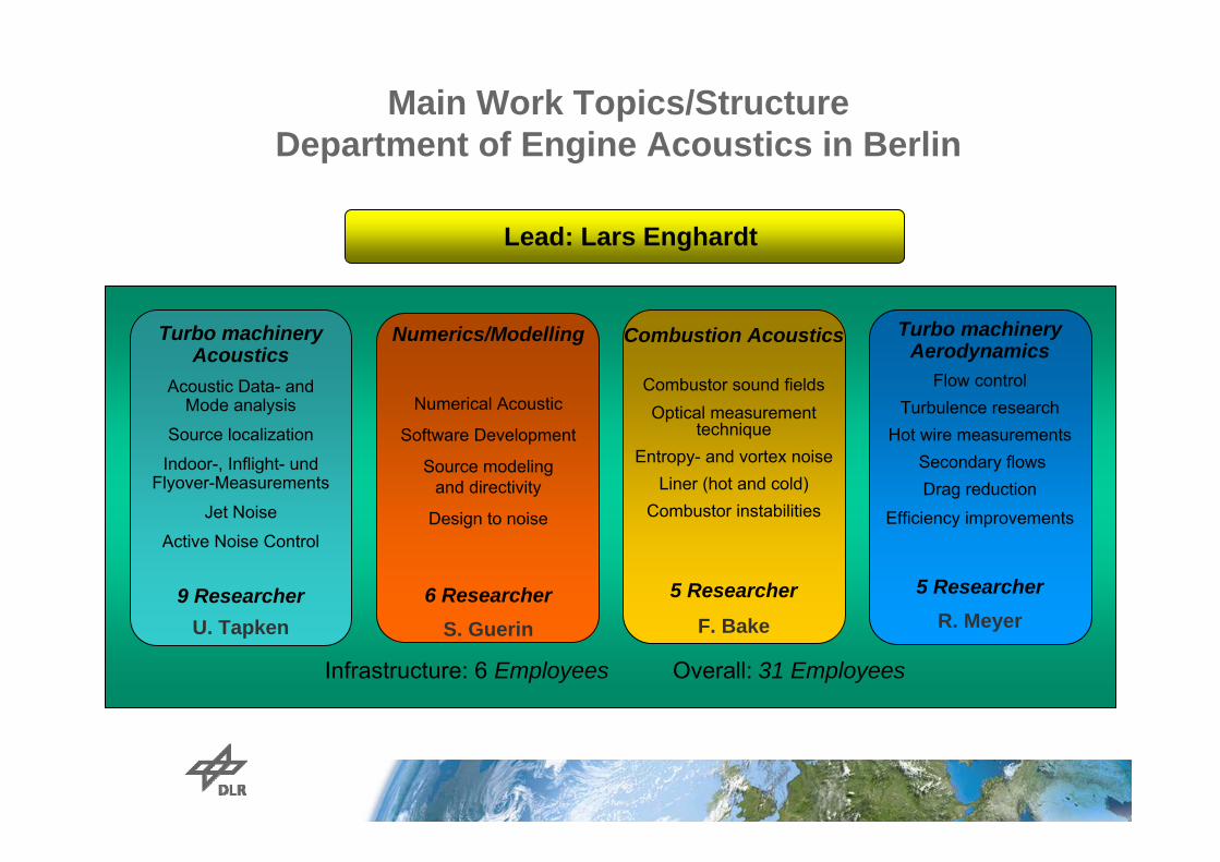
Infrastructure: 6 Employees Overall: 31 Employees
Main Work Topics/Structure Department of Engine Acoustics in Berlin
Turbo machinery Acoustics
Acoustic Data- and Mode analysis
Source localization
Indoor-, Inflight- und Flyover-Measurements
Jet Noise
Active Noise Control
9 ResearcherU. Tapken
Lead: Lars Enghardt
Combustion Acoustics
Combustor sound fieldsOptical measurement
techniqueEntropy- and vortex noise
Liner (hot and cold)Combustor instabilities
5 Researcher
F. Bake
Turbo machinery Aerodynamics
Flow controlTurbulence research
Hot wire measurementsSecondary flows Drag reduction
Efficiency improvements
5 ResearcherR. Meyer
Numerics/Modelling
Numerical Acoustic
Software Development
Source modeling and directivity
Design to noise
6 ResearcherS. Guerin
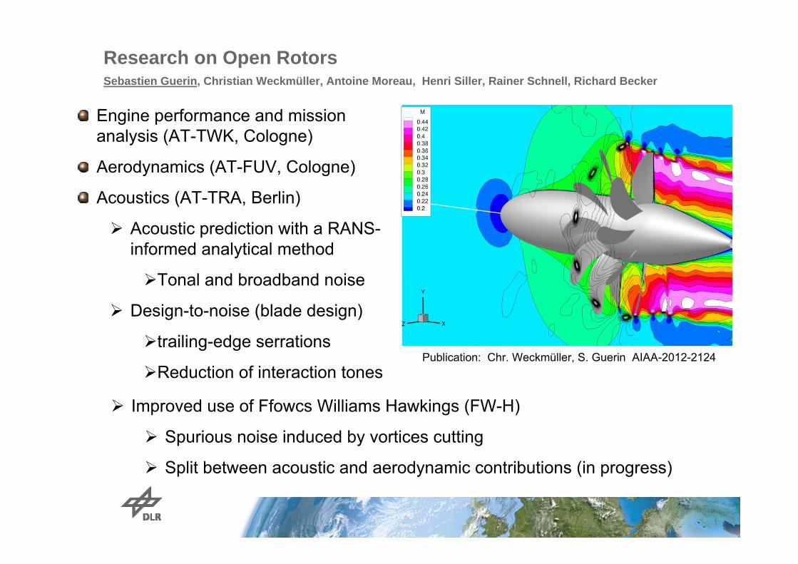
Research on Open RotorsSebastien Guerin, Christian Weckmüller, Antoine Moreau, Henri Siller, Rainer Schnell, Richard Becker
Engine performance and mission analysis (AT-TWK, Cologne)
Aerodynamics (AT-FUV, Cologne)
Acoustics (AT-TRA, Berlin)
Acoustic prediction with a RANS-informed analytical method
Tonal and broadband noise
Design-to-noise (blade design)
trailing-edge serrations
Reduction of interaction tones
Improved use of Ffowcs Williams Hawkings (FW-H)
Spurious noise induced by vortices cutting
Split between acoustic and aerodynamic contributions (in progress)
Publication: Chr. Weckmüller, S. Guerin AIAA-2012-2124

Design capabilities: trailing-edge serrations Broadening of the wake
Reduction of interaction tones
C. Weckmüller, S. Guérin; On the influence of trailing-edge serrations on open-rotor tonal noise, AIAA 2012-2124.
sound power levelfont-rotor wake
baseline serrated TE

TEENI – Turbo shaft Engine Exhaust Noise Identification European FP7 research project, 1.4.2008-31.03.2013,
Lead: TurboMeca (France), 11partners from 10 countries
Focus: Experimental identification of the contributions of each of the engine modules to exhaust broadband noise
Turbo shaft exhaust noise: a mix of combustion and turbine noise, with very little jet noise representative for “core noise”
TEENI work program is divided in 3 interdependent Work packages (WP)
• WP1 : Innovative sensors development –to provide reference measurements of fluctuating quantities within the engine under harsh operating conditions.
• WP2 : Noise Sources Breakdown Techniques to determine the dominant emission location/s from external measurements (taking the internal measurements into account)
• WP3 : Turboshaft engine full-scale testapply WP1 and WP2 developments
Karsten Knobloch, Friedrich Bake, Ulf Tapken, Werner Jürgens, Benjamin Pardowitz, André Fischer

New probes for high pressure applicationsMicrophone probes- Mean pressure up to 20bar (during test 12bar) - Temperature up to 1200°C- Fluctuations <1bar (194dB)- 6 specific length probes,30 standard probes at the
nozzle
Calibration
Twin Thermocouples• Thermocouples Type R, Pt/Rh (87/13%) / Pt
Tmax≈1600°C, short time Tmax≈1700°C- Temp fluctuations up to at least 800Hz- Two thermocouples of different diameter (and different
time constant) allow for correction of time signal by iterative post-processing
Publication: K. Knobloch et al GT2011-45705
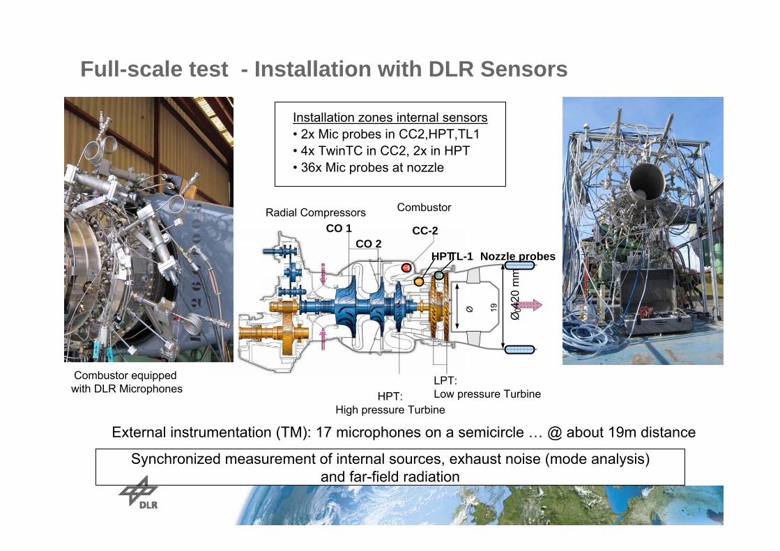
Full-scale test - Installation with DLR Sensors
Ø42
0 m
m
CC-2
HPTTL-1 Nozzle probes
CO 1 CO 2
Ø 19 0
Installation zones internal sensors• 2x Mic probes in CC2,HPT,TL1• 4x TwinTC in CC2, 2x in HPT• 36x Mic probes at nozzle
CombustorRadial Compressors
HPT:High pressure Turbine
LPT:Low pressure Turbine
External instrumentation (TM): 17 microphones on a semicircle … @ about 19m distance
Synchronized measurement of internal sources, exhaust noise (mode analysis) and far-field radiation
Combustor equipped with DLR Microphones

Mode analysis using internal reference sensors / Separation of different noise source contributions
FB1FB2 FB3 FB4 FB5
- FB1 and FB2: - all sources strongly contribute
to dominant mode m=0- FB3:
- all sources contribute to dominant mode m=+1
- HPT and TL contribute to m=0- only HPT contributes to m=-1
- FB4:- combustor and HPT contribute
more to m=-2 - TL contributes more to m=0
and m=+2 - FB5:
- HPT and TL contribute mainly to m=-2, m=-1 and m=+3
Analysis of data base is still on-going!
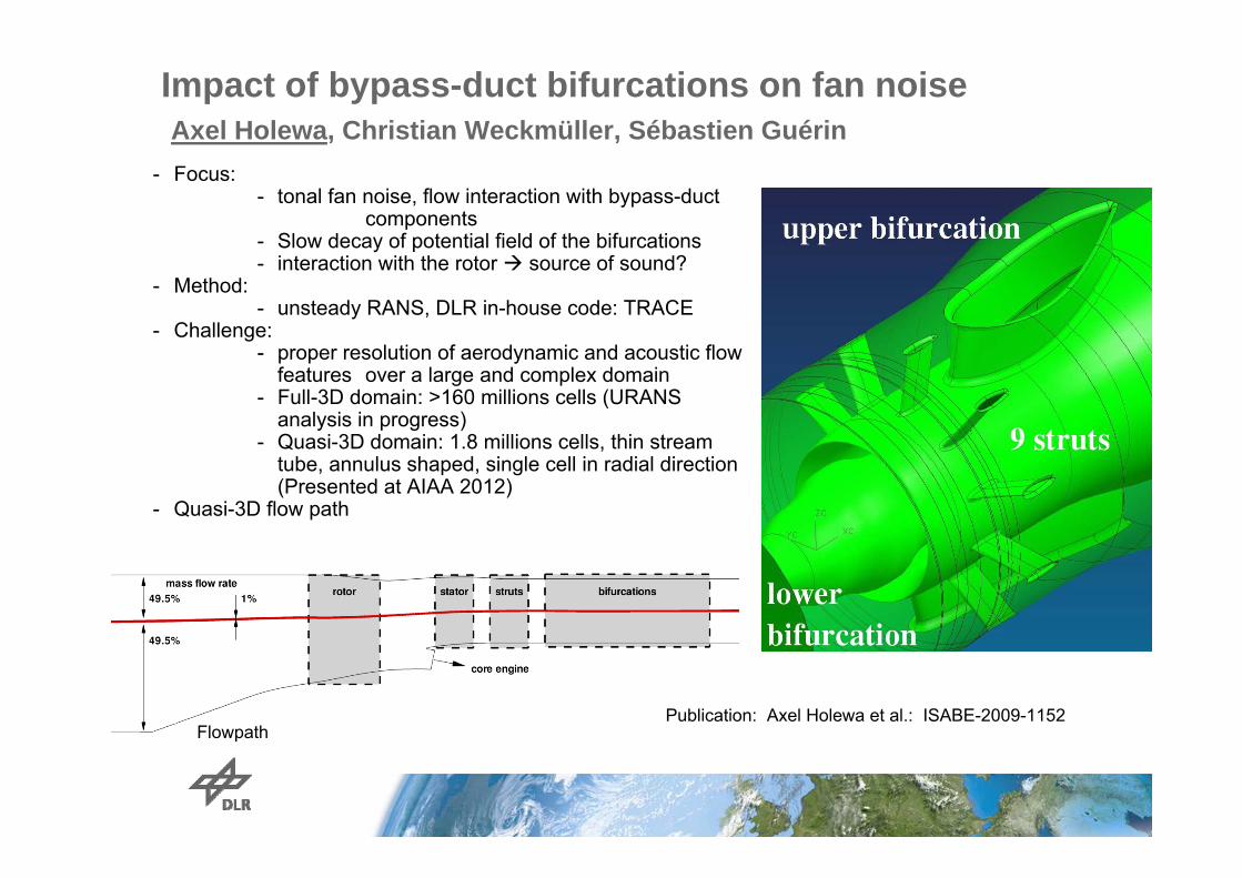
Impact of bypass-duct bifurcations on fan noiseAxel Holewa, Christian Weckmüller, Sébastien Guérin
- Focus: - tonal fan noise, flow interaction with bypass-duct
components- Slow decay of potential field of the bifurcations- interaction with the rotor source of sound?
- Method: - unsteady RANS, DLR in-house code: TRACE
- Challenge: - proper resolution of aerodynamic and acoustic flow
features over a large and complex domain- Full-3D domain: >160 millions cells (URANS
analysis in progress)- Quasi-3D domain: 1.8 millions cells, thin stream
tube, annulus shaped, single cell in radial direction (Presented at AIAA 2012)
- Quasi-3D flow path
FlowpathPublication: Axel Holewa et al.: ISABE-2009-1152

Instantaneous pressure fieldAxial decay of the potential field
Isolated fan stage
Fan stage with bifurcations
Quasi-3D results

Rotor—blade forces in the rotating frame
Forces on the stator vanes
Time domain Isolated fan stage Fan stage with bifurcations
Acoustic mode decomposition in the bypass duct
- TS modes less strong- Additional broadband mode
spectra- Total sound power increases
by 2-3 dB at 1 BPF and 2 BPF
1 BPF 2 BPF

Reduction of subsonic jet noise by passive flow control devices (Joint PSU & DLR experiments)
Robert Meyer, Ching-Wen Kuo, Dennis K. McLaughlin
Publication: Robert Meyer; Ching–Wen Kuo; Dennis K. McLaughlin: AIAA-Aero acoustics Berlin 2013
• Enhancement of turbulent mixing• Experiments at high subsonic
Mach numbers (0.5-1.0)• Variation of Zigzag shape
• Thickness, jag width,..• Microphone measurements with • Near field ring array • Fare field arc array
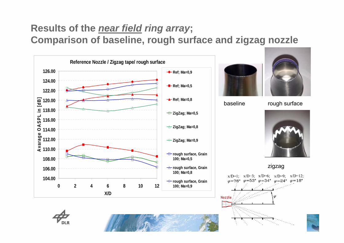
Results of the near field ring array; Comparison of baseline, rough surface and zigzag nozzle
Reference Nozzle / Zigzag tape/ rough surface
104.00
106.00
108.00
110.00
112.00
114.00
116.00
118.00
120.00
122.00
124.00
126.00
0 2 4 6 8 10 12X/D
Ava
rage
OA
SPL
in [d
B]
Ref; Ma=0,9
Ref; Ma=0,5
Ref; Ma=0,8
ZigZag; Ma=0,5
ZigZag; Ma=0,8
ZigZag; Ma=0,9
rough surface, Grain100; Ma=0,5
rough surface, Grain100; Ma=0,8
rough surface, Grain100; Ma=0,9
rough surface
zigzag
baseline

Variation of zigzag height: Nozzle with zigzag tape; Ma= 1.0
baseline Zigzag tape
605,78.920.2DLR II
605,78,92,160.4DLR I
605,78.41.900.4PSU I
Phi[°]
t [mm]
B [mm]
a [mm]
h [mm]
Zigzagtype
Thank you for your attention