dl2e hardware reference - delta t · 2016-10-06 · bridge measurements_____109 potentiometer ......
TRANSCRIPT

User Manual for
DL2e Data Logger
Hardware Reference
Delta-T Devices Ltd
Version 3

VERSION
Document code : DL2-UM-05-03Version : 3Issued : 15 Dec 2000
See also :Getting Started,Ls2Win on-line Help.
TRADEMARKS
IBM PC, PC-XT, PC-AT, PS/2 and PC-DOS are registered trademarks of InternationalBusiness Machines Corporation
MS-DOS, Windows and Windows NT are registered trademarks of MicrosoftCorporation
Lotus 1-2-3 is a registered trademark of Lotus Development Corporation
Hayes is a registered trademark of Hayes Microcomputer Products Inc.
COPYRIGHT
This manual is Copyright © 1992, 1993, 1996,2000 Delta-T Devices Ltd., 128 LowRoad, Burwell, Cambridge CB5 0EJ, UK. All rights reserved.
Under the copyright laws, this book may not be copied in whole or in part, without thewritten consent of Delta-T Devices Ltd. Under the law, copying includes translationinto another language.
ELECTRO-MAGNETIC COMPATIBILITY
The DL2e Logger has been assessed under the European Union EMC Directive89/336/EEC, and conforms with the following harmonised emissions and immunitystandards
EN 50081-1 : 1992 EN 50082-1 : 1992:

DL2e Hardware Reference Page iii
Contents
Contents_____________________________________________________________________ iii
Hardware Reference ____________________________________________________________7About this manual_______________________________________________________________________7
Other Documents and Help.______________________________________________________________7
Chapter 1 : About the DL2e Logger _______________________________________________9Waking and sleeping_____________________________________________________________________9
Waking the logger_____________________________________________________________________9Putting the logger to Sleep______________________________________________________________10Autosleep __________________________________________________________________________10
Logging _____________________________________________________________________________10LOG, EVENT, WARM-UP _____________________________________________________________10Conflicting priority tasks _______________________________________________________________11
The logger’s keypad and display ___________________________________________________________12Using the logger’s keypad and display_____________________________________________________12Summary of keypad functions ___________________________________________________________13
Resetting the logger ____________________________________________________________________15Coldbooting ________________________________________________________________________15Warm reset _________________________________________________________________________16
Password ____________________________________________________________________________17Setting the logger’s clock ________________________________________________________________18
Using Ls2Win _______________________________________________________________________18Using the keypad/display_______________________________________________________________18
Chapter 2 : Interrogating the DL2e logger _________________________________________19Logger status _________________________________________________________________________19
Using Ls2Win _______________________________________________________________________21Using the keypad/display_______________________________________________________________21
Sensors status _________________________________________________________________________22What the Sensors status provides _________________________________________________________22Using Ls2Win _______________________________________________________________________23Using the keypad/display_______________________________________________________________23
Error status ___________________________________________________________________________24Using Ls2Win _______________________________________________________________________26Using the keypad/display_______________________________________________________________26
Chapter 3 : Starting and Stopping Logging _________________________________________27Starting logging________________________________________________________________________27
Using Ls2Win _______________________________________________________________________27Using the keypad/display_______________________________________________________________28
Stopping logging_______________________________________________________________________29Using Ls2Win _______________________________________________________________________29Using the keypad/display_______________________________________________________________29
Chapter 4 : Collecting and Erasing Logged Data_____________________________________30Data collection options __________________________________________________________________30

Contents
Page iv DL2e Hardware Reference
Using Ls2Win _______________________________________________________________________ 32Outputting data directly to a printer_________________________________________________________ 33
Preparation _________________________________________________________________________ 33Checking printer operation _____________________________________________________________ 33Using the keypad/display ______________________________________________________________ 34Auto-printing _______________________________________________________________________ 35To stop auto-printing: _________________________________________________________________ 35
Using other data collection devices _________________________________________________________ 36Data integrity checks __________________________________________________________________ 36Handshaking________________________________________________________________________ 36Continuous data collection as a backup ____________________________________________________ 37
Erasing data from the logger’s memory ______________________________________________________ 37Using Ls2Win _______________________________________________________________________ 37Using the keypad/display ______________________________________________________________ 37
Chapter 5 : DL2e Logger Hardware ______________________________________________39Power supplies ________________________________________________________________________ 41
Internal battery operation ______________________________________________________________ 41Lithium cell_________________________________________________________________________ 42External power supplies _______________________________________________________________ 43WARNINGS________________________________________________________________________ 44
Rechargeable battery pack, type LBK1 ______________________________________________________ 46Assembling the battery pack ____________________________________________________________ 47Fitting the battery pack to the logger ______________________________________________________ 47Recharging _________________________________________________________________________ 47IMPORTANT WARNINGS ____________________________________________________________ 48Overload protection___________________________________________________________________ 48
Electrical mains environment _____________________________________________________________ 48Display (contrast) ______________________________________________________________________ 49Installing IC’s _________________________________________________________________________ 49Communication parameters_______________________________________________________________ 50Communication cables __________________________________________________________________ 51
The logger’s RS232 serial port configuration________________________________________________ 51Computer cables _____________________________________________________________________ 52Cables for printers ____________________________________________________________________ 52
Testing communication__________________________________________________________________ 53Terminal mode ______________________________________________________________________ 53Echo test___________________________________________________________________________ 53Diagnosing faults ____________________________________________________________________ 54Other causes of communication problems __________________________________________________ 54
Field installation _______________________________________________________________________ 55Temperature ________________________________________________________________________ 55Moisture ___________________________________________________________________________ 55
Maintenance, Storage, Repairs and Recalibration ______________________________________________ 57Maintenance ________________________________________________________________________ 57Storage ____________________________________________________________________________ 57Repairs ____________________________________________________________________________ 57Recalibration service__________________________________________________________________ 57
Warranty and Service ___________________________________________________________________ 58Terms and Conditions of Sale ___________________________________________________________ 58Service and Spares ___________________________________________________________________ 58Technical Support ____________________________________________________________________ 59
Chapter 6 : Sensors and Input Cards _____________________________________________60Overview of electrical measurement techniques _______________________________________________ 60
Digital signals _______________________________________________________________________ 60Analogue signals _____________________________________________________________________ 60Analogue input cards _________________________________________________________________ 61Supplementary cards __________________________________________________________________ 61Voltage measurements ________________________________________________________________ 61Current measurement _________________________________________________________________ 62

Contents
DL2e Hardware Reference Page v
Resistance measurements ______________________________________________________________62Measuring small changes in resistance_____________________________________________________63Potentiometric measurements ___________________________________________________________63Power supplies to sensors (and other devices) _______________________________________________64Summary of cards and on-board channels __________________________________________________65Summary of connections for analogue measurements _________________________________________66
Input and supplementary cards ____________________________________________________________67Installing input cards __________________________________________________________________67Removing and fitting ribbon cables _______________________________________________________68
Analogue Input Card, type LAC1 __________________________________________________________6915-ch mode _________________________________________________________________________6930-ch mode _________________________________________________________________________69Input protection (15-ch and 30-ch modes) __________________________________________________70
Analogue Input Card, type ACD1 __________________________________________________________734-Wire Card, type LFW1_________________________________________________________________75Attenuator Card, type LPR1 Input Protection Card, type LPR1V ___________________________________80AC Excitation Card, type ACS1 ___________________________________________________________83Voltage, single-ended ___________________________________________________________________86Voltage, differential_____________________________________________________________________89Voltage, up to ±50V DC _________________________________________________________________92Earth loops and common mode voltages _____________________________________________________95
Earth loops _________________________________________________________________________95Common mode voltages _______________________________________________________________96
Current ______________________________________________________________________________98Resistance, 2-wire _____________________________________________________________________101Resistance, 3-wire _____________________________________________________________________104Resistance, 4-wire _____________________________________________________________________106Selecting a suitable excitation current ______________________________________________________108Bridge measurements __________________________________________________________________109Potentiometer ________________________________________________________________________113Digital inputs, and Counter Card type DLC1 _________________________________________________115
Timing accuracy ____________________________________________________________________118Providing additional digital status channels ________________________________________________120
Relay channels _______________________________________________________________________121Intermittent logging - using relay and event trigger combinations _________________________________126
Requirement _______________________________________________________________________126Explanation ________________________________________________________________________126Manual control of logging _____________________________________________________________126Example Program and Wiring for Intermittent Logging _______________________________________127
Thermistors__________________________________________________________________________128Using thermistors with the logger _______________________________________________________128
Platinum Resistance Thermometer and other RTDs ____________________________________________131Using PT100 And other RTDs with the DL2e logger _________________________________________131
Thermocouples _______________________________________________________________________133
Appendices__________________________________________________________________136
Appendix A : DL2e Technical Specifications ______________________________________ 138Logging ____________________________________________________________________________138
Logging interval and speed ____________________________________________________________138Input channels ______________________________________________________________________138
Analogue inputs ______________________________________________________________________138Analogue Card, LAC1________________________________________________________________138Analogue Card, ACD1________________________________________________________________1384-Wire Card, LFW1__________________________________________________________________138Attenuator Card, LPR1 _______________________________________________________________140Input Protection Card, LPR1V__________________________________________________________140
Digital inputs and outputs _______________________________________________________________141Digital inputs ______________________________________________________________________141Relay outputs ______________________________________________________________________141Counter Card, DLC1 _________________________________________________________________141

Contents
Page vi DL2e Hardware Reference
Other specifications ___________________________________________________________________ 142Rechargeable battery pack LBK1 _________________________________________________________ 143Electro-Magnetic Compatibility __________________________________________________________ 143
Appendix B : Accuracy of logger readings ________________________________________ 144Adding errors from different sources _____________________________________________________ 144
Analogue accuracy ____________________________________________________________________ 145Voltage reading accuracy _____________________________________________________________ 145Resistance reading accuracy ___________________________________________________________ 146Calculation of logger analogue accuracy: a worked example ___________________________________ 147
Arithmetic accuracy ___________________________________________________________________ 148Analogue sensors: linear conversion to engineering units _____________________________________ 148Counter and frequency sensors: linear conversion to engineering units ___________________________ 148Linearisation errors __________________________________________________________________ 149
Appendix C: Calculating the speed of data readings_________________________________ 150
Appendix D : Resident linearisation tables ________________________________________ 152Thermistor tables _____________________________________________________________________ 153Thermocouple tables___________________________________________________________________ 154
Appendix E : Identifying components on cards ____________________________________ 155
Index ______________________________________________________________________156

Hardware ReferenceAbout this manual
DL2e Hardware Reference Page 7
Hardware Reference
About this manualThis manual contains information about:
• using the keypad on the front panel
• power supplies and the rechargeable battery pack
• setting internal switches and rebooting,
• installing additional cards and components,
• connecting sensors
• connecting cable assemblies
• communications cables and modems
• sensor linearisation tables
• accuracy and technical specifications
• maintenance, storage, repairs and guarantee.
It also contains general guidance on the scope and application of the measurementtechniques supported by the logger.
Other Documents and Help.See the "Getting Started" manual for:
• Installation instructions.
• A Guided Tour for an introduction to some of the logger’s facilities.
• Learn the basics of logger operation in the Tutorial.
• A brief introduction to features not covered in the tutorial.
View the on-line Help or press F1 in each of the Ls2Win applications for help onusing the Windows software:
Sensor Application Notes, including wiring instructions, are provided on-line in thesensor library in the DL2Program Editor.You can print off individual on-line Help topics.Use all the Indexes and Contents Lists - in this manual, Getting Started, and in theon-line Help for Ls2Win. They are all different.
Separate Contents andIndexes exist for :- each on-line Help,- Hardware Reference,- Getting Started.
So keep searching!

Hardware ReferenceAbout this manual
Page 8 DL2e Hardware Reference
Note the following specialist, technical manuals:
• DL2e Technical Reference manual, consisting solely of printed circuit boardschematics for the various cards and accessories.
• DL2e Programmers Guide . This contains terse information for programmersabout communicating with the logger. It is provided on your installation disk as atext file.

Hardware Reference About the DL2e LoggerWaking and sleeping
DL2e Hardware Reference Page 9
Chapter 1 : About the DL2e LoggerThe DL2e logger unit contains all the hardware required for capturing and storing datafrom a wide variety of different types of sensor, under most environmental conditions.It runs an internal logging program that is set up by the user, and tells the logger howand when to acquire data.
The logger’s front panel keypad and display gives control over the essential featureswhich are needed for field operation away from a computer, such as starting andstopping the logger, displaying current readings, providing status reports, andoutputting logged data to a local printer or intermediate collection device.
The Windows software Ls2Win also provides control over all the features availablefrom the front panel keypad. It also is used to program the logger. This involveschoosing the number of channels to be logged, the types of sensor and appropriate dataconversions, the rate at which each channel is to be logged, and action to be taken onout-of-limits conditions.
It also provides a range of other features that are not available from the keypad, such astimed start, triggering on events, collecting and manipulating logged data.
Password facilityCertain logger functions are protected from unauthorised use by a password facility.This is set up in the logging program using the DL2e Program Editor, which is part ofLs2Win. See also the on-line Help.
Waking and sleepingThe DL2e Logger can exist in one of two states, known as ‘awake’ and ‘asleep’,corresponding to high and low levels of activity.
AwakeWhen awake all of the logger’s circuitry is powered up and all its functions are active.The logger is awake during a LOG, WARM-UP or EVENT (see opposite), and whilecommunicating via its RS232 port, or performing any of the tasks controlled from itskeypad. There is normally a message displayed on the logger’s display, and this is thesimplest way to recognise when the logger is awake. Typical current consumption inthe awake state is 40mA.
AsleepWhen asleep a minimum number of components are powered up, notably the clock (tokeep time), memory (to conserve data), and circuitry which enables the logger to bewoken. The logger’s display is always blank when the logger is asleep. Typical currentconsumption in the asleep state is 40µA.
Waking the loggerThe logger wakes of its own accord whenever required to LOG, EVENT, or WARM-UP. See Logging, opposite.
To use the logger’s keypad functions press the WAKE key.
An incoming signal at the logger’s RS232 port wakes the logger. This occurs when youcommunicate with the logger from your PC using the DL2 Control Panel, which isinstalled on your desktop as part of Ls2Win.

About the DL2e Logger Hardware ReferenceLogging
Page 10 DL2e Hardware Reference
Putting the logger to SleepThe asleep state is the logger’s preferred state, with low power consumption for batteryconservation. The logger automatically sleeps if it has woken specifically to LOG,EVENT, or WARM-UP (i.e. provided that it is not also busy communicating oroperating under keypad control).
In other situations, the logger autosleeps if it receives no input from a user (i.e. a keypress, or communication via its RS232 port) within a reasonable period of time.
There is no manual method of putting the logger to sleep from the keypad: the logger issimply left to autosleep.
The logger can be put to sleep by a warm reset (see page 16), but this method is notrecommended for routine use.
AutosleepThe logger autosleeps in the following conditions:
After 10 seconds when displaying the Keypad main menu if no key is pressed.
Within a few seconds if the logger is woken by noise at its RS232 port, such as mayoccur if the power supply to a printer or computer is switched while connected to thelogger. The logger discriminates between noise and a genuine attempt to communicateby waiting a few seconds for further signal.
After one or two minutes if no user input occurs (i.e. a key press or communicationsignal) at any other time.
Autosleeping can be disabled when using the ‘auto-print’ feature.See "Auto-printing" on page 35.
LoggingAfter starting logging, the logger normally autosleeps, and then wakes when required totake readings from sensors or to switch warm-up relays. The logger is said to be‘logging’, even though it is not actually recording data at a given instant, for example inmessages such as ‘logging started..’ or ‘already logging’.
LOG, EVENT, WARM-UPWhile logging, recording of data may be initiated either by the logger’s internal clock(readings taken at regular intervals, known as ‘timed’ data), or by a signal on a channelprogrammed as a data trigger (or ‘event triggered’ data). Switching of a warm-up relayis controlled by the logger’s clock.
These tasks take priority over keypad functions and communication. When carrying outone of these ‘priority tasks’, the logger flashes up a message on its display to indicatethat other logger functions are temporarily suspended.
The respective messages are:
• For recording timed data:
LOG
• For recording event triggered data:
EVENT
• For switching a warm-up relay:

Hardware Reference About the DL2e LoggerLogging
DL2e Hardware Reference Page 11
WARM-UP
The logger is said to be performing a LOG, EVENT or WARM-UP.
While communicating with the logger, you may notice appreciable delays inresponding to your key presses while the logger is busy performing a priority task. Ifthe logger is programmed to log timed data very frequently you may find it difficult toestablish communication with the logger, and data collection may be appreciablyslower than normal.
Occasionally the logger may attempt to display the message off screen (off the edge ofthe logger’s display). This is unusual, most likely to occur when the logger isdisplaying a General status report. You may then notice a delay in keypad operationwithout any message being displayed.
Conflicting priority tasksIt is possible for an event trigger to occur while the logger is busy logging timed data,and for timed data to become due while the logger is servicing an EVENT. If so, thelogger completes the first priority task before tackling the second one.
As a result, there may be a discrepancy between the time recorded by the logger in itsdata file, and the actual time when an EVENT occurred, or when data was actuallylogged (see "Timing accuracy" on page 118 for details).
If a LOG becomes due while the logger is still working on a previous LOG, an over-runoccurs (see " Over-runs" on page 26 for details).
EVENT detection is disabled on an event trigger channel while the logger is busyservicing a previous EVENT on the same event trigger channel. The logger may missevents occurring in short succession.

About the DL2e Logger Hardware ReferenceThe logger’s keypad and display
Page 12 DL2e Hardware Reference
The logger’s keypad and display
Using the logger’s keypad and displayTo use the logger’s keypad, wake the logger by pressing WAKE.
You must press WAKE while the logger is asleep. Any message on the screen indicatesthat the logger is already awake, for example communicating or performing a LOG.Disconnect any serial communication cable and allow the logger to autosleep (ifautosleeping has not been disabled). In emergency try a warm reset or, as a last resort,coldboot the logger (see "Coldbooting" on page 15).
On its display, the logger echoes the key press:
<WAKE>
Keypad main menuThe logger displays General Status and Malfunction Reports (see "Logger " on page 19and page "Error status" on page 24), followed by a message, known as the Keypadmain menu:
Press key ifrequired..
Keypad functionsYou can now press any key to enter one of the logger’s seven ‘keypad functions’. Thekeypad functions are named after the logger’s seven keys, and are summarisedopposite.
Note that you can curtail the General Status and Malfunction Reports at any time bypressing one of the keys. If you hold the key down, you can also omit the main menumessage and go directly into one of the keypad functions.
On entering a keypad function, for example READ, the logger first confirms the keypress by displaying the name of the selected function.
<READ>
On exiting any of the keypad functions, the logger always returns to the Keypad mainmenu. Note however, that the logger may autosleep if left too long without a key press.
There is no keypad function for putting the logger to sleep. The logger autosleeps (see"Autosleep" on page 10).
Entering informationSome of the keypad functions require you to enter information, for example date andtime, password or a selection from a menu. To do so, use σ and/or θ until the value oroption that you require comes up on the display. To accept the displayed option pressthe key corresponding to the keypad function that you are using.
The logger displays a prompt such as:

Hardware Reference About the DL2e LoggerThe logger’s keypad and display
DL2e Hardware Reference Page 13
use <UP> <DOWN>& <SET TIME>..
Confirming a selectionSome of the keypad operations require confirmation before proceeding, for exampleerasing data or stopping logging. To confirm, press the key for the keypad function thatyou are using. In the example below, press START to execute the operation yourequested. Pressing any other key, or leaving the logger to autosleep, aborts theoperation.
The logger displays a prompt such as:
<START> confirmsother keys abort
Summary of keypad functionsThe keypad functions are named after their corresponding keys: WAKE, σ,θ, READ,SET TIME, START and PRINT.
WAKEThe WAKE function displays a General status report:
• Battery voltage and expected life
• Current date and time.
• Configuration name
• Whether logging or not
• Date and time of start and end of logging, if appropriate
• Amount of memory installed and number of stored data.
• Malfunction Reports: battery failed, memory filled and suspect data logged on anychannel.
See "Logger " on page 19 for details.
READThe READ function is for checking a logging set up before or during logging:
• Displays instantaneous values on input channels
• Displays status of relay and event trigger channels.
• Permits switching of relay channels under keypad control.
See page 23 for details.
SET TIMEThe SET TIME function sets the time on the logger’s internal clock.
See "Setting the logger’s clock" on page 18 for details.
STARTThe START function starts and stops logging. See "Starting and Stopping Logging" onpage 27 for details.
PRINTThe PRINT function can be used to:
• Print out data on a serial printer.

About the DL2e Logger Hardware ReferenceThe logger’s keypad and display
Page 14 DL2e Hardware Reference
• Output data in binary file format to a data collection terminal (not using Logger PCSoftware).
• Erase data.
See "Collecting and Erasing Logged Data" on page 30 for details.
σThe σ function is for testing two-way serial communication, e.g. with a computer. See"Error! Reference source not found." on page Error! Bookmark not defined. fordetails.
θThe θ function is for testing one way serial communication, e.g. with a printer. See"Checking printer operation" on page 33 for details.

Hardware Reference About the DL2e LoggerResetting the logger
DL2e Hardware Reference Page 15
Resetting the logger
ColdbootingColdbooting restores the logger to a known basic state with the followingconsequences:
• Any data stored in the logger is erased.
• The logger carries out a RAM check, checking which RAM chip positions areoccupied, and whether any RAM chips are faulty.
• The existing logging program is erased and the default configuration is installed.
• Any Setup string for PRINT is erased.XXXX See "Setup string for PRINT" in the on-line Help.
• Auto-wrap (previously called the overwrite mode) is disabled.See "Auto-Wrap" in the on-line Help.
The logger’s clock is not reset.
The logger automatically coldboots on waking if a new PROM is installed.
The logger must be coldbooted if:
• RAM chips have been moved or installed
• The logger has crashed irretrievably for any reason, and a warm reset (seeopposite) fails.
• Input cards have been removed or installed, i.e. plugged into or out of the inputcard stack.
The logger does not need to be coldbooted if only switches or ribbon cables have beenmoved, or if attenuator or input protection cards types LPR1, LPR1V have beeninstalled.
To coldboot the logger• Open the logger’s case.
• Hold down the ‘COLD BOOT’ and ‘STOP’ buttons on the main circuit board(see Figure 2 - Main circuit board layout), and then -
Ø if the logger is asleep, also press WAKE on the logger’s keypad,
Ø if the logger is already awake, also press the ‘RESET’ button on the logger’smain circuit board (see Figure 2).
• The message ‘coldbooting..’ appears on the logger’s display, followed by asequence of reports as the logger checks RAM chips, installs a DEFAULT loggingprogram (described in Tutorial Lesson 3 in the Getting Started manual), and goesto sleep.
Ensure that the sequence of reports above does occur. Any other type of messageindicates that the logger is not in fact coldbooting.
Note that the logger also coldboots if the logger wakes for any reason while the ‘COLDBOOT’ and ‘STOP’ buttons are held down.
In extreme circumstances, you may have to remove all power from the logger beforecoldbooting. Disconnect any external power supply, remove the logger’s internalbatteries, gently lift the spring terminal from the top of the lithium cell (see "Lithiumcell" on page 42) with a fingernail, and hold for 10 seconds. Replace the logger’sbatteries and coldboot as described above.

About the DL2e Logger Hardware ReferenceResetting the logger
Page 16 DL2e Hardware Reference
Warm resetA ‘warm reset’ puts the logger to sleep without destroying any information in thelogger’s memory (data, configuration, etc.). The logger can be woken to resume normaloperation after a warm reset. Warm reset is not as drastic as coldbooting. Try it inpreference to coldbooting if the logger crashes and gets stuck in an awake state.Coldboot only as a last resort if a warm reset fails.
The logger normally autosleeps of its own accord and warm reset should not be used toroutinely put the logger to sleep. In particular, beware of resetting the logger while it isin the middle of a LOG, EVENT or WARM-UP. This may interfere with the setting ofthe logger’s clock in preparation for the next LOG, and have an unpredictable effect onlogging of timed data.
To carry out a warm reset• Open the logger’s case.
• Press and release the ‘RESET’ button (see Figure 2). When the button is released,the logger’s display goes blank.
• Repeat if necessary.

Hardware Reference About the DL2e LoggerPassword
DL2e Hardware Reference Page 17
PasswordThe DL2e Logger has a password facility for preventing loss of data or interruption oflogging due to unauthorised use of the logger’s keypad or PC software.The password is set up as part of the logging program.
Once the logger is programmed with a password, the user has to enter it in order toperform the following operations:
• erase data from the logger’s memory
• stop logging
• start logging, if data is stored in the logger
• re-program the logger, if data is stored in the logger
The password does not need to be entered in order to use any other keypad or softwarefunction.
To program the logger with a passwordOpen or create a logging program using the DL2 Program Editor.Enter up to 8 alphabetic characters in the Password box.Send the program to the logger in the normal way.
Note that the logger’s keypad and display only offers upper case alphabetical charactersand spaces. If your password contains lower case or non-alphabetical characters youcannot enter it from the logger’s keypad. (You can do this using any PC software.)
When prompted for a passwordUsing Ls2Win
DL2 Control Panel pops up the Password dialog, which prompts you to enter thelogger’s password.
Remember to use upper case or you will be locked out from using some of the Keypadfunctions.
Using the keypad/displayWhen a password is required, a prompt appears on the top line and the cursor moves tothe left position on the bottom line.
password..?_
Use σ and θ to cycle through the alphabet.
When the correct character appears, press the key corresponding to the keypad functionyou are using: PRINT if erasing data, START if starting or stopping logging. Thecursor will move to the next position.
Enter 8 characters. If the password has less than eight characters, enter spaces to makeup 8 characters. To enter a space, press PRINT or START, as appropriate, withoutpressing σ or θ.
RemarksYou can recall the logger’s current password by retrieving the logging program fromthe logger.

About the DL2e Logger Hardware ReferenceSetting the logger’s clock
Page 18 DL2e Hardware Reference
Setting the logger’s clockThe logger has an internal clock that marks the date and time of all logged data. Thedate and time can be set either from the program or from the front panel keypad. Youcannot set the clock while the logger is logging.
Leap YearsThe logger does not keep track of years and cannot identify leap years. February isalways assumed to have 28 days. In a leap year, the logger’s date has to be set to thecorrect date manually after 29th February.
Using Ls2WinSee the on-line Help in the PC's DL2 Control Panel program.
Using the keypad/displayAt the Keypad main menu, press SET TIME.The logger displays the following messages:
required..<SET TIME>
use <UP> <DOWN>& <SET TIME>
The logger displays the date and time.
& <SET TIME>date: 28-01
The date is in European (day-month, dd-mm) or American (month-day, mm-dd) format,depending on the setting of the ‘50/60’ switch (see "Electrical mains environment" onpage 48). The time is formatted as hours:minutes:seconds, hh:mm:ss.
Use σ and τ to adjust the value indicated by the cursor, and press SET TIME when thedisplayed value is correct. The cursor then moves onto the next field. Note that the firstvalue that you set is always the month, irrespective of the date format.
The logger’s clock is actually set at the moment you press SET TIME to set the numberof seconds.
date: 28-01time: 15:29:30

Hardware Reference Interrogating the DL2e loggerLogger status
DL2e Hardware Reference Page 19
Chapter 2 : Interrogating the DL2e loggerThis chapter describes facilities that allow you to examine the current state of thelogger.
Status information is supplied on the following:
• Logger, including battery voltage, date and time, logging program name, andmemory status.
• Sensor channels, comprising instantaneous readings on input channels and status ofrelay and event trigger channels. If using the logger’s keypad, relay channels canalso be exercised (i.e. turned on and off for testing purposes).
• Datasets, including the amount of memory used and available
• Errors (malfunctions reports), i.e. whether any problems have occurred while theDL2e Logger has been logging, including full memory, battery failure, and suspectdata on input channels. Malfunction reports can be deleted so that only newmalfunctions get reported on the next occasion.
Either WAKE the logger from the Front Panel, or run a DL2 Control Panel on your PC.
General Status ReportA general status report appears transiently on the Front Panel when you wake thelogger. This information may also be viewed in the DL2 Control Panel on your PC.
See also the on-line Help available in each of the following component programs of theWindows software Ls2WIN:
• DL2 Program Editor - to create and edit logging programs.
• DL2 Control Panel - to control and monitor the logger
• Dataset Import Wizard - to retrieve logged data into Microsoft Excel.
• DL2 Dataset Viewer - to view raw data files once saved to your PC.
Logger statusLogger status information is displayed on the Logger and Datasets panels, in the DL2Control Panel on your PC.It also appears transiently on the DL2e Front Panel as part of the general status reportwhen you wake the logger.
PROM versionThe PROM version is only shown on your PC - in the Logger panel in the DL2 ControlPanel. It does not appear on the logger’s Front Panel Display.
Battery voltage and % life expectancyThe reported battery voltage is the voltage available to power the logger.The voltage available to power the logger is not always the full battery or externalpower supply voltage, being reduced by a diode drop (approximately 0.6V) in thefollowing cases:
• If the logger is powered from an external power supply
• If the logger is powered from its internal batteries with the power supply selectorswitch set to ‘EXTERNAL’.
The reported battery voltage is intended as a guideline only. Fluctuations may occurdue to polarisation effects in the logger’s internal alkaline cells. In particular, thebatteries appear to recover during a long period of inactivity, but their voltage then fallsrapidly to its previous level when the logger is awake.

Interrogating the DL2e logger Hardware ReferenceLogger status
Page 20 DL2e Hardware Reference
The battery life is calculated on the basis of a linear interpolation between 7V (0% left)and 8.5V (99% left) and applies to alkaline cells only. A battery voltage in excess of10V is reported as >10V, and voltages in excess of 8.5V are reported as 99% left.
Figure 1 - Battery life interpolation
Date and timeThe formatting of the date is linked to the setting of the ‘50/60’ switch (see Figure 2 -Main circuit board layout):
• ‘50’ gives European date formatting (i.e. day-month).
• ‘60’ gives American date formatting (i.e. month-day).
Leap yearsThe logger does not keep track of years, and cannot identify leap years. February isalways assumed to have 28 days. In a leap year you must re-set the correct datemanually after 29th February.
Program (or configuration) nameThis is the name of the file containing the logging instructions that you download fromthe PC to the logging program that is installed in the logger and which tells it when tolog, which channels to log, how to record results and so on. The Front Panel displaycalls this the configuration, abbreviated to "config'n". In Ls2Win call this the loggingprogram.
Logging startedShows the date and time when a command to start logging was issued. It is the date andtime of a key press (if logging has been started from the keypad), or a command issuedby means of the PC, and not the precise date and time of the first logged data:
• For an immediate start, either using the PC or the keypad, there is a short delaybetween issuing the instruction to start and the first logged data: the reported timemay be up to 2 seconds earlier than the time of the first logged data.
• If the logger is set to start at a pre-set time, or set for a triggered start, there isgenerally a longer time delay between issuing the instruction to start logging andthe first logged data.
Standing byThis message indicates that the logger is not yet logging, and contains no stored datafrom a previous logging session.

Hardware Reference Interrogating the DL2e loggerLogger status
DL2e Hardware Reference Page 21
Logging stoppedShows the date and time when logging stopped automatically (as a result of its memoryfilling up or detection of a battery failure: see "Low battery" on page 41), or wasterminated from the keypad or PC. This may not necessarily be the same as the timeand date of the last logged reading.
RAM STATUS andSTORED DATA
The logger’s memory may be partitioned into up to three independent areas or‘datasets’.
• One area can be set aside for timed data (i.e. data stored at the regular timeintervals specified in the logging program).
• Two areas can be set aside for event triggered data (that is data stored when eventsare detected on event trigger channels) if channels 61 and 62 are programmed asevent trigger channels.
These areas of memory are referred to as TIMED RAM, TRIG/61 RAM and TRIG/62RAM or datasets respectively, and their status is reported separately.
Note that:
• 1K is 1024 bytes, and that each reading requires 2 bytes of memory.
• All TIMED RAM is available for data, for example 128K of TIMED RAM is131072 bytes, and can store 65536 readings.
• Event triggered data is stored with an additional 7 bytes of date and timeinformation for each repetition of an event triggered sequence, and the number ofevent triggered data that can be stored in a given amount of memory is reducedaccordingly.
• DL2 Control Panel also reports the number of data since data was last retrieved.These readings can be retrieved from the logger separately. See the on-line Helpfor details.
• Auto-wrap mode allows the logger to continue logging timed data when TIMEDRAM fills up, by overwriting old data (See the on-line Help for details). Auto-wrapmode status is only reported by Ls2Win.
See also the on-line help for the DL2 Control Panel program.
Using Ls2WinThe DL2 Control Panel displays logger status information. See also its on-line Help andLesson 2 in "Getting Started".
Using the keypad/displayAt the Keypad main menu, or while the logger is asleep, press WAKE.The status report consists of a sequence of messages, each of which is displayed forapproximately two seconds.It can be curtailed at any point by pressing any key.

Interrogating the DL2e logger Hardware ReferenceSensors status
Page 22 DL2e Hardware Reference
Sensors status
What the Sensors status providesThis shows the current status of all channels that have been programmed as sensors. Itcan be displayed on your PC in the Sensors panel of the DL2 Control Panel, or on thelogger's Front Panel display, using the keypad READ function.
The DL2 Control Panel displays a single value for each channel.The READ function continuously updates the displayed value for a single channel,allowing sensor connections to be conveniently tested. Relay channels can be exercisedand event trigger channels can be tested prior to starting logging.This information is independent of logging, and can be obtained before or whilelogging with no interference to logged data.
Each channel is identified by a number, label, and sensor code (for input channels) orby a channel function (for other non-input types of channel).
Input channelsThe READ button on the Front Panel, or the Sensors panel in the DL2 Control Panel,either gives an instantaneous reading in engineering units, or it gives an error messageif appropriate. See also: Error status on page 24 for interpretation of error messages,and the additional notes below for counter and frequency channels.
Counter channelsIf the logger is logging, the selected channel(s) show the accumulated count withoutaffecting logged data.If the logger is not logging, the counter is reset to zero before returning a ChannelReport.
Using the READ function, an updated accumulating count is displayed.
DL2 Control Panel displays only a single value, and not an accumulating count. If notlogging, this is normally zero, unless you apply a high frequency input signal.
Frequency type channelsThe logger samples frequency inputs over ½ second periods. Hence it has a resolutionof 2 Hz for this purpose (e.g. for an input signal of 1 Hz, the display alternates between0 and 2 Hz). Note that this does not apply for logged data, when the resolution offrequency channels corresponds to the selected sampling interval
Relay channelsThe status of a relay channel (MAL, OUT and WRM functions) is either ON or OFF.Using the keypad READ function, the relays can be exercised for testing purposes (see"Using the keypad/display" on page 23).
Sensors powered through warm-up relays are normally only powered up during thewarm-up periods specified in the logging program.
To obtain valid readings from a ‘warmed-up’ channel, the warm-up relay has tobe switched ON.
Warm-up relays are aautomatically switiched ON when you select a channel and pressRead Now in the Sensors panel of the DL2 Control Panel.
Remember you must manually switch warm-up relays ON when using the keypadREAD function (see page 23).

Hardware Reference Interrogating the DL2e loggerSensors status
DL2e Hardware Reference Page 23
On exiting the status report, warm-up relays are returned to the state required forlogging, i.e. ON in a warm-up period, OFF otherwise. However, if logging is inprogress, the logger switches warm-up relays OFF at the end of a warm-up period, evenif they have been switched ON for a Channel Report. If this occurs, you will see faultyreadings from warmed-up channels.
Event trigger channelsEvent trigger channels are reported as being either a s-trigger (start trigger), or d-trigger(data trigger), with a status SET or CLR (clear).When SET, the channel detects events and the logger acts accordingly.When CLR, the channel ignores events.
Both start and data trigger channels are CLR when the logger receives a program, andbecome SET when logging is started.When a start trigger detects an EVENT, the logger starts recording data and the starttrigger becomes CLR, ignoring any further events.Data trigger channels remain SET until logging is stopped or event triggered memoryfills up.
Using Ls2WinSensor status information is displayed in the Sensors panel of DL2 Control Panel. Seealso its on-line Help and Lesson 2 in "Getting Started".
Using the keypad/displayAt the Keypad main menu press READ.The logger displays the sensor code and label for channel 1, or the first programmedchannel (in numerical order) if channel 1 is not programmed).
ch reading units1 TM1 cold-jn
After a pause, the sensor code and label are replaced with a reading in engineeringunits, or by an error message if the sensor is faulty or incorrectly connected.
ch reading units1_ 20.95 deg C
Error messages may be o/s limits (outside limits), over-range, or noisy. Theseconditions are discussed in detail on page "Sensor malfunctions" on page 25.
ch reading units 1_ o/s limits
The display is up-dated regularly until:
• you press σ or τ to move on to another channel
• you press READ to exit the READ function, and return to the Keypad main menu
• the logger autosleeps
To change channelsPress σ or τ.The reading on the next (or previous) programmed channel in numerical order will bedisplayed.
1 20.95 deg C2_ 999.9 ohm
Note: Even if two channels are displayed, only the channel marked by the underlinecursor is updated (i.e. channel 2 in this example).

Interrogating the DL2e logger Hardware ReferenceError status
Page 24 DL2e Hardware Reference
Fast scrollingHold down σ or τ for fast scrolling through the channels.
Exercising relay channelsWhen you move onto a relay channel, the logger initially displays its status, and thenswitches the relay between ON and OFF states at 2s intervals.
When σ or τ are pressed to move onto another channel, the relay remains switched inthe state last displayed. You can use this feature to power up a sensor manually, whichduring normal logger operation would need to be powered using the warm-up relay(WRM) function.On exiting the READ function, or when the logger autosleeps, the relays are returned totheir normal state (i.e. the state they would be in if they had not been switched by theREAD function).Note that logging requirements take priority over manual operation of the relays. If thelogger wakes to LOG or WARM-UP, it will override any manual settings of a relay. Inparticular, the logger will not allow a warm-up relay to be switched off manually duringa warm-up period preceding a reading.
Testing event trigger channelsAn event trigger channel in the CLR state does not normally detect events. Whenreporting its status, the logger activates the trigger in a test mode. Events are thendetected and an EVENT message displayed, but the normal trigger function remainsdisabled.
When finished...Press READ to return to the Keypad main menu.
Error statusDuring logging, the logger detects and acts on four categories of malfunction:
• Battery failure
• Memory full
• Sensor malfunctions
• Over-run errors
The action taken by the logger on encountering each of these malfunctions andassociated malfunction reports is described in "Sensor malfunctions" below.The logger’s WAKE function and the Errors panel in the PC's DL2 Control Panelreports battery, memory and sensor malfunctions (but not over-runs).
Battery failureThe logger reads the battery voltage each time it wakes. If the voltage available topower the logger is less than 7.0 Volts:
• The logger briefly displays battery failure on its display.
• If logging, the logger stops logging, compiles a malfunction report and switchesthe malfunction-warning relay (if programmed). This is to conserve any remainingbattery life and avoid any risk of corrupting or losing logged data.
• The logger autosleeps.
RemarksThe logger can only perform this routine if there is enough power available for thelogger to wake. If the power supply becomes completely disconnected, the logger willbe unable to take any action. On reconnection of the power supply, the logger will failto report battery failure. If logging, the most likely outcome is a series of over-runerrors as the logger attempts to catch up on lost logging opportunities.

Hardware Reference Interrogating the DL2e loggerError status
DL2e Hardware Reference Page 25
The mechanism for detecting battery failure is not the same as for reading the batteryvoltage when reporting Logger status. The logger may not detect a battery failure eventhough it reports a battery voltage less than 7V, or the logger may have detected abattery failure, while reporting a battery voltage greater than 7V (due to battery de-polarisation).
Memory fullIf an area of the logger’s memory (TIMED, TRIG/61, TRIG/62) fills up, the logger:
• Briefly displays the message memory full.
• Stops logging data of the relevant data type (TIMED, TRIG/61 or TRIG/62).
• Compiles a malfunction report.
• Switches the malfunction warning relay (if programmed).If all areas of the logger’s memory are full, the logger also stops logging. This isreported on the Logger panel of the PC's DL2 Control Panel and in the status reportdisplayed on the Front Panel.
Sensor malfunctionsThe logger detects three categories of sensor malfunction: over range, noisy and outsidelimits. If they occur during a channel report, they are simply reported in error messages.On detecting a sensor malfunction while logging data, the logger takes the followingaction:
• Flags the logged data with the appropriate flag (see on-line Help).
• Compiles a malfunction report, indicating the type of sensor malfunction, and, if itis the first malfunction recorded for that particular channel, the date and time. Notethat the malfunction report is more specific than the flags attached to data or errormessages displayed in the Sensors status report:
• Switches on the malfunction warning relay (if programmed).Note : The logger cannot detect errors whist issuing a sensors/channel status report.That is, data are not flagged and the malfunction report and malfunction warning relayare not affected by malfunctions detected during a Sensors status report, even if thelogger is logging.
Over rangeAn over range condition occurs if:
• On analogue channels, the logger’s full scale input range of ±2.096 Volts has beenexceeded (for resistance channels this is equivalent to 1048 kΩ , 104.8 kΩ , 10.48kΩ , and 1048 Ω for excitation currents of 2, 20, 200, 2000 µA respectively).
• On counter channels, a count of 65472 has been exceeded.
• On averaged channels, the accumulated total of readings within the averagingperiod has exceeded the logger’s arithmetical capacity, 2x10⁹ µV, or for non-linearsensors, 2 x 10⁷ engineering units. This is reported as ave too large inmalfunction reports.
• For non-linear sensors, the input falls outside the linearisation table. This isreported as outside table in malfunction reports.
• A valid cold-junction temperature is not available for a thermocouple channel thatrequires a cold-junction reference. This is reported as bad cold-jn. in malfunctionreports.
NoisyThe logger will not autorange both up and down during a single reading. It records avalue in the less sensitive range and flags the reading as noisy.
Outside limitUpper and lower limits for valid readings can be set to any reasonable level and willusually be the most sensitive test for malfunction (see Valid Range in the on-line Help).

Interrogating the DL2e logger Hardware ReferenceError status
Page 26 DL2e Hardware Reference
Outside limits readings are reported as outside limit in malfunction reports, and as o/slimits in Channel Reports.
Over-runsOver-runs occur when storing timed data if the logger finds that the time for its nextLOG has already passed. Whenever this happens, the logger saves time by storingcopies of previous readings (or adding them to averages etc.) instead of taking newreadings. This is very unlikely to occur in normal use, but might happen if:
• The logger is programmed to read faster than it is able to, e.g. 60 thermistors every5 seconds. See Appendix C for information about logging speed.
• The logger is programmed to read close to the limits of its speed and an unusualcoincidence causes it to be exceptionally slow, e.g. all channels requiringautoranging on the same LOG (as can happen on the very first LOG).
• The logger is programmed to log timed and event triggered data, and the length oftime spent recording triggered data is sufficient to cause it to over-run on timedreadings.
Storing faulty dataReadings involving either sensor malfunctions or over-runs are recorded with lowerresolution (10 bits instead of 12 bits). See also the on-line Help.Faulty readings do not contribute to the minimum and maximum values in data fileheaders. See also the on-line Help.If problems occur with individual readings on a channel employing data compression,the resulting compressed values are flagged accordingly.
Deleting malfunction reportsMalfunction reports can be deleted from the logger’s memory, so that in future thelogger reports fresh occurrences of malfunctions only. Deleting malfunction reportsalso resets the malfunction warning relay to OFF, if programmed. Any flagged datastored in the logger’s memory remain flagged.
Using Ls2WinThe DL2 Control Panel displays error status information in the Errors panel. See alsoits on-line Help.
Using the keypad/displayDisplaying malfunction reports
Press the WAKE key to wake the logger. BATTERY FAILURE, MEMORY FILLEDand sensor malfunction reports are then displayed after the logger status report.
To end malfunction reports, at any time, press any key on the logger’s keypad.
To delete malfunction reportsAfter displaying the malfunction reports, the logger offers the option of deleting them.
to delete report_
Press WAKE to delete the malfunction reports, or any other key if you want to retainthem in the logger’s memory.
<WAKE> confirmsother keys abort

Hardware Reference Starting and Stopping LoggingStarting logging
DL2e Hardware Reference Page 27
Chapter 3 : Starting and Stopping Logging
Starting logging
Logging may be started from the keypad, or using the PC's DL2 Control Panelprogram. Three different methods of starting the logger are available:
• Immediate start
• Pre-set time start
• Event triggered start
Any data stored in the logger is erased on starting. The logger issues a warning toremind you that data is to be erased. If the logger is programmed with a password, youwill have to enter the password in order to proceed.
As soon as the logger receives the instruction to start logging, it considers itself to be ina logging condition. The Logger Status indicates that Logging has started. Resetting thelogger’s clock is not permitted, even if the logger has not yet logged any data. Inparticular, note that this applies to timed and event triggered starts, when a considerabletime interval can elapse between issuing the instruction to start logging and actuallystoring the first data.
The logger stores the time of receiving the instruction to start. This is the time reportedin the Logger panel of the DL2 Control Panel (see "Logger " on page 19), and does notcoincide precisely with the time of the first logged data (even for immediate start).
Immediate StartThis method of starting occurs if logging is started from the keypad, or if the immediatestart option is selected using the PC. The logger sets its clock to log timed data as soonas possible after receiving the command to do so. There may be a 2-second delaybetween issuing the command and the first logged timed data.If a start trigger channel has been programmed, event triggered starting occurs instead(see below).
To start logging at a pre-set timeUsing the PC, the logger can be made to start at a pre-set date and time (for example,on 31st January at midnight).
Event triggered startThe logger can be armed to start logging when a signal is detected on channel 61.
The logger must be programmed with channel 61 as a start trigger channel (see on-lineHelp). When started from the logger’s keypad, or using the immediate start option viathe PC, the logger will delay logging until it receives a signal on channel 61.
Note that this is different from the action of a data trigger. After an event triggered start,the logger proceeds logging as if an ordinary immediate start had occurred, acquiringtimed data at regular intervals, with no further inputs required on the start triggerchannel. A data trigger causes the data to be logged whenever an input is detected onthe data trigger channel, in parallel with timed data.
Using Ls2WinClick Start or Re-start in the Logger panel of DL2 Control Panel, then make a selectionfrom the available options in the Start Logging dialog. See also the on-line help.

Starting and Stopping Logging Hardware ReferenceStarting logging
Page 28 DL2e Hardware Reference
Using the keypad/displayEvent triggered start only
For a triggered start, first program channel 61 as a start trigger (see on-line Help). Thenproceed as for Immediate start.
Immediate startAt the Keypad main menu, press START.
<START>
If the logger is already logging, you are asked if you want to stop logging (see StoppingLogging, on page 29).
already loggingto STOP:
If data exists from a previous logging session, you will be asked if you want to erase it.
28 readingsto be erased
If the logger contains data and is programmed with a password, you will be promptedto enter it.
password..?
The logger prompts you to press START again to confirm that you want to start loggingand erase any previous data. Press any other key if you decide not to start logging.
<START> confirmsother keys abort
If the logger has been programmed with a Start trigger channel, a message appearsindicating that the start trigger is set, i.e. awaiting a signal to start logging.
start triggerset..
If there is no start trigger channel, the first LOG starts after 1 to 2 seconds.
other keys abortlogging started
The message LOG appears briefly, indicating that a set of timed readings has beentaken.
other keys abortLOG ing started

Hardware Reference Starting and Stopping LoggingStopping logging
DL2e Hardware Reference Page 29
Stopping loggingLogging may be stopped by using either the front panel keypad or via the PC. There isalso an internal ‘STOP’ button. Note there are no facilities using an event trigger tostop logging, nor for stopping at a pre-set time.
Stopping logging is protected by passwords (except if the ‘STOP’ button is used).There is no need to stop logging in order to collect logged data, or to use any otherWindows software or front panel function.
Logging stops automatically in the event of a battery failure. If the memory availablefor a data type (TIMED, TRIG/61, TRIG/62) fills up, the logger stops logging data ofthat data type (but note that overwrite mode allows the logger to continue logging timeddata).
Using Ls2WinClick Stop in the Logger panel of DL2 Control Panel.
Using the keypad/displayAt the Keypad main menu, press START.
<START>
A message indicates that the logger is already logging. If this message does not appear,then this procedure will start logging instead of stopping it (see the previous section).
already loggingto STOP:
If the logger contains stored data and is also programmed with a password, you areprompted to enter it.
password..?
Press START again to confirm that you want to stop logging. Press any other key if youdecide not to stop logging.
<START> confirmsother keys abort
Logging stops after confirmation and the logger returns to the main menu.
logging stopped
Using the internal STOP buttonOpen the logger’s lid, and hold down the STOP button (see Figure 2 - Main circuitboard layout). While the STOP button is held down, do one of the following:
• If the logger is asleep, wake the logger by pressing WAKE.
• If the logger is already awake, press the RESET button (see Figure 2 - Main circuitboard layout).
Logging will also stop if the STOP button is held down when the logger wakes of itsown accord in order to log data.
This method of stopping logging is not protected by passwords.

Collecting and Erasing Logged Data Hardware ReferenceData collection options
Page 30 DL2e Hardware Reference
Chapter 4 : Collecting and Erasing Logged DataData can be collected from the logger at any time during logging. There is no need tostop logging.
Data output from the logger can be controlled either from the logger’s keypad, or fromyour PC.Data that you have collected can be erased from the logger’s memory to create spacefor more data. By repeatedly collecting and erasing data, you can acquire as much dataas you like (regardless of the logger’s memory capacity) without interrupting logging.You can collect data from the logger in the following ways:
• Printing out data directly from the logger using a printer.
• Using the Dataset Panel in the PC's DL2 Control Panel to collect data to acomputer file. Data files can be imported in to Microsoft Excel directly usingDataset Import Wizard, or converted to comma separated ASCII (.dat) format fileswhich are suitable for importing into other data processing programs
• Using the Data Import Wizard to import data directly into a Microsoft ExcelSpreadsheet.
• Outputting data to an intermediate data collection device, and subsequentlytransferring to a computer for further processing. Suitable devices may be stand-alone disks, cassette drives, solid state data collection terminals or simplecomputers that are unable to run Ls2Win.
Regardless of the technique used, you will have to specify the format, quantity, datatype and starting point of the data to be collected. These options and the techniquesthemselves are described below.Two related features that you may find useful are:
• Auto-printing: the logger can be set up to output data automatically whenever itstores new data to its memory (see the on-line Help).
• Auto-wrap (or Overwrite mode): automatic overwriting of old data when thelogger’s memory fills up (see the on-line Help for the DL2 Control Panel).
Note that data stored in the logger’s memory cannot be displayed directly on thelogger’s display or computer screen. It must first be collected to a disk file usingLs2Win.
Data collection optionsData type
The logger partitions its memory and stores and outputs timed and event triggered dataseparately. Ls2Win refers to these as TIMED, TRIG/61 and TRIG/62 ‘datasets’. Thelogger refers to tham as ‘data types’.
File formatThe DL2e system makes use of four data formats, referred to by their associated filename suffices: .BIN, .HFD, .DAT and .PRN.In Ls2Win you will see references to .bin, .hfd and .dat formats. If you use the keypadto output data, you will be offered .PRN and .BIN formats.
.BIN , .HFDThe .BIN format is a binary format containing compressed data (2 bytes per reading),as retrieved from the logger using a fast binary protocol or output directly from thelogger using the PRINT function.

Hardware Reference Collecting and Erasing Logged DataData collection options
DL2e Hardware Reference Page 31
The .HFD format is a hexadecimal format containing compressed data (4 bytes perreading), retrieved from the logger using a hexadecimal protocol – which permitsfrequent checks during transmission but is substantially slower than the binary protocol.Both these file formats can be imported directly into Microsoft Excel using DatasetImport Wizard, or you can open them for viewing in Dataset Viewer – DL2 ControlPanel does this for you automatically after retrieving a dataset.Neither of these file formats are suitable for printing, or importing into other dataprocessing programs directly. They need to be converted to .DAT format: open the filein Dataset Viewer and select the Save As command (File menu).Their structure is described in the DL2e Programmers’ Guide.
.DATComma separated ASCII format, with text enclosed in double quotes and data valuesseparated by commas.
The Save As command (File menu) in Dataset Viewer creates .DAT files from .BIN or.HFD files. The detailed file structure is described in the Reference Topics section ofDataset Viewer’s on-line Help.
.DAT files can be input directly into many data processing software packages, and areeasily read by programmes written in common computing languages. They can also beimported into Microsoft Excel using Dataset Import Wizard.
.DAT files can be viewed and printed out directly (for example using Notepad), but thepresentation is cluttered with quotes and commas.
.PRNPrintable ASCII format, with data in engineering units, space separated and aligned incolumns.The .PRN format is suitable for printing directly.
The contents and arrangement of data is similar to .DAT files, with the following majordifferences:
• Items are separated by spaces instead of commas, and aligned in columns
• Text items are not enclosed in double quotes
• Error flags are appended to readings (instead of preceding the reading that theyrefer to)
Data starting..The logger keeps a record of where to find the first item of data in its memory and, if ithas been outputting data, a record of where to find the next data to be output.
The logger can thus allow you to specify whether you want to collect data whichfollows on from the last data that you have collected (‘follow-on data’), or to duplicatethe data that you have already collected (i.e. data starting from the first item in thelogger’s memory).You will only be offered this choice if you have already collected data from the loggeron one or more occasions, and not erased it from the logger’s memory. You cannot ofcourse collect data that you have erased from the logger’s memory.
Differences between timed and event triggered dataWhen collecting timed data, you will be prompted with the date and time of the firstline of data that will be output.When collecting event-triggered data you will be prompted with the date and time ofthe last line of data which was collected on the previous occasion (and which will notbe collected again).
Number of data (to be output)Your logger may contain more data than you can handle in a single disk file. If youdon’t want to collect all the data stored in the logger into a single file, you can specifythe number of readings you require. You can then collect another batch of data thatfollows on from the first file, and so on.

Collecting and Erasing Logged Data Hardware ReferenceData collection options
Page 32 DL2e Hardware Reference
Note that the number you specify will be only approximate, as the logger has to outputcomplete ‘lines’ of data. A line of data is a group of readings that have been stored onany single occasion, and appear on a single line in a printout or .DAT file.The size of a data file depends on the logging program as well as the number of data itcontains. For a given quantity of data, a configuration with a small number of inputchannels (and hence a lot of lines) will produce a larger data file than a configurationwith many input channels (and hence few lines).
Size of filesThe table below shows the number of bytes in each element (File Header, ChannelHeader, Date-time, and Reading) in the various formats of logger data files. You cancalculate the size of data files from:File size (bytes) = (r x number of readings) + (d x number of lines of data) + (c xnumber of channels in data file) + h
Data type TIMED TRIG/61 and TRIG/62File format .DAT .HFD .BIN .DAT .HFD .BINfile header h 219 248 120 221 248 120Channel header c 90 38 30 90 38 30Date-time d 24 8 1 24 24 9Reading r 15 4 2 15 4 2
Using Ls2WinIn the Datasets panel of DL2 Control Panel, select the dataset in which you want toerase readings, click Retrieve, and make suitable selections in the Retrieve Datasetdialog.

Hardware Reference Collecting and Erasing Logged DataOutputting data directly to a printer
DL2e Hardware Reference Page 33
Outputting data directly to a printerThe front panel PRINT function is used to output data directly from the logger to aprinter. (You may find it faster and more convenient to use the PC to collect data to adisk file and to obtain a printout from that, see the on-line Help).
Preparation
Requirements• a printer with an RS232 serial interface (not parallel)
• a suitable cable. "Communication cables" on page 51 describes how to construct asuitable cable. Loggers-to-computer cables are generally not suitable.
Communication parametersThe logger’s communications parameters (baud rate, data bits and parity) must be set tomatch those of the printer (see "Communication parameters" on page 50). Refer to yourprinter’s manual for information about setting the printer’s communication parameters.When the logger is subsequently connected back to a PC, the logger’s communicationparameters must be reset to match those in the Properties dialogue of the PC's DL2Control Panel program. If you change the logger’s communication parameters, theneither reset the logger’s internal switches to their original positions after printing, ormodify the settings in the Properties window next time you use the DL2 Control Panelprogram.
HandshakingSet the printer for hardware handshaking (see "Handshaking" on page 36).
Connection to printerConnect the printer to the logger’s RS232 connector using a suitable cable, and set theprinter on-line.
Checking printer operationA simple test is available to ensure that the logger is communicating correctly with aprinter.
At the logger’s main menu, press τ. The logger outputs a sequence of printablecharacters.
<DOWN> printer test.._
If the logger and printer are correctly connected and set up, the printer will repeatedlyprint out the following sequence:!"#$%&’()*+,-./0123456789::<=>?@ABCDEFGHIJKLMNOPQRSTUVWXYZ[]^_’abcdefghijklmnopqrstuvwxyz|~
To stop the printer press any key.

Collecting and Erasing Logged Data Hardware ReferenceOutputting data directly to a printer
Page 34 DL2e Hardware Reference
Troubleshooting printer problemsCommon problems and likely causes are:
Symptom Likely cause
No printout at all or very intermittentprinting
Faulty or incorrectly wired cable
Complete nonsense Logger/printer baud rate or data bits settingnot matched.
Approximately half of the printoutincorrect, e.g. italics or nonsensecharacters.
Logger printer parity settings not matched
Several lines of correctly formattedprintout followed by missing data.
Incorrect wiring of handshake line in cable,or wrong type of handshake set up inprinter.
Using the keypad/displayAt the Keypad main menu, press PRINT.
In the menus that follow, use σ and τ to toggle between the options, and press PRINTto accept the option displayed.
use <UP> <DOWN>& <PRINT>
Select PRINT, and press PRINT to accept.
PRINT or ERASE..PRINT
Select TIMED, TRIG/61 or TRIG/62 as required, and press PRINT to accept.
DATA TYPE..?TIMED
The message inactive source indicates that the logger is not programmed to record thetype of data you have selected.
inactive source
Select .PRN format. The alternative .BIN format is unsuitable for printing but youmight choose it if using an alternative data collection device(see "Using other data collection devices" on page 36.
FORMAT..?.PRN
Select a date and time for the first logged data that you want to have output:
data starting...11/07 15:46:03
Specify the number of readings to be output. If there are less than 1K (1024) readingsstored, all readings is the only option. Otherwise you can choose a number of Kreadings. If you want to auto-print, select all readings.

Hardware Reference Collecting and Erasing Logged DataOutputting data directly to a printer
DL2e Hardware Reference Page 35
number of data all readings
Ensure your printer is connected and online. Press PRINT to confirm that the abovechoices are correct, and to start printing.
<PRINT> confirmsother keys abort
The message "printing.." indicates that the logger is busy outputting data. Whenfinished, the logger either offers auto-printing (see below) or returns to the Keypadmain menu.
printing..
Auto-printingAuto-printing allows you to print out data of a specified type automatically as it islogged to memory.First start logging. The logger only offers the auto-print option if it is already logging.
Select the PRINT function, select the data type (TIMED, TRIG/61, TRIG/62) that youwant to auto-print, select all readings and confirm.When the logger has finished printing all the data up to the present time, it offers theoption to auto-print.
AUTO-PRINTyes
Disabling autosleepSome printers and data collection devices may spuriously interpret powering up of thelogger’s serial port as a character (for example, when the logger wakes to log data).
To prevent this happening, you can disable autosleep by selecting no in theAUTOSLEEP menu, but note that this will result in greatly increased powerconsumption.
AUTOSLEEPno
The logger now returns to the Keypad main menu.Auto-printing does not interfere with the logger’s keypad functions, and you can usethe PC to communicate with the logger in the normal manner. The logger suspendsauto-printing while the serial port is busy with another function (for example,communicating). The backlog of data is output on the next occasion when the loggerwould normally auto-print (i.e. when data of the given type is next due to be logged).
Note: To disable autosleep, fit a shorting link on the main board in position H2. SeeFigure 2 - Main circuit board layout.
To stop auto-printing:At the Keypad main menu, press PRINT.If the logger has been auto-printing, it stops auto-printing and exits the PRINT function.
endingauto-print..

Collecting and Erasing Logged Data Hardware ReferenceUsing other data collection devices
Page 36 DL2e Hardware Reference
Using other data collection devicesIt is possible to use any data storage device with a suitable RS232 serial port forcollecting data from the logger. The process is identical to outputting data to a printer,except that you can choose the .BIN format option. You can then transfer the data toyour PC for processing as required.This technique may be of interest if you need to collect data from a logger situated at aremote site without interrupting logging. However, if you have to purchase a piece ofequipment specifically for this purpose, we strongly recommend that you consider aportable PC instead: it will be considerably more flexible, and probably not much moreexpensive than a portable floppy disk drive or dedicated data collection terminal.Suitable devices may be stand-alone disks, cassette drives, solid-state data-collectionterminals or simple computers which are unable to run Ls2Win. We don’t support anyspecific piece of equipment, and can only offer general advice here. Refer to the usermanual supplied with the equipment for information on how to set it to receive datafrom the logger, and for procedures for transferring data to a computer.
If the device requires a sequence of control codes to initialise it for receiving data, thismay be set up using the Setup string for PRINT facility (see the on-line Help), but onlyfor .PRN format data.
Data output in .PRN format is slow. If your equipment is capable of receiving 8-bitdata, then .BIN format is strongly recommended. The data can then be transferred toyour computer for conversion into .DAT format using the PC. Remember that it isessential to use an 8-bit serial word format to collect .BIN format data.
Data integrity checksFor .BIN format data, the logger performs bytecount and checksum calculations anddisplays the results when it has finished outputting the data.
13576 byteschecksum = 22143
These values enable you to verify that data has been correctly received. The bytecountis simply the number of bytes of data the logger has output. The checksum is calculatedby adding together the binary values of each byte of data, (ignoring overflow in excessof FFFFh). Both values are displayed in decimal.If the data collection device also performs bytecount and checksum calculations, youcan compare the results to verify the integrity of the data you have collected.
HandshakingYour equipment may be unable to store data as fast as the logger transmits it, especially.BIN format data. To avoid losing data, your equipment should have a facility for‘handshaking’. This controls the data output from the logger to a rate the equipment canaccept, so that none is lost. Refer to the equipment’s user manual for details of how toimplement its handshaking facility.The logger can respond to two forms of handshaking: hardware handshaking, andsoftware or XON/XOFF handshaking. Hardware handshaking is only suitable for .PRNformat data output. Follow the instructions in Communication cables, page"Communication cables" on page 51, for constructing a printer cable.
XON/XOFF handshaking is only available when the logger is transmitting .BIN formatdata. In XON/XOFF handshaking, the receiving equipment transmits an XOFFcharacter (ASCII code 19) to the logger when a pause in data transmission is required,and an XON character (ASCII code 17) when ready for data transmission to resume.Since the XON and XOFF information is received in the same way as any otherincoming data, a simple 3-wire cable (transmitted data, received data and 0V) issufficient to implement XON/XOFF handshaking. See "Communication cables" onpage 51 for details of the logger’s RS232 connector.

Hardware Reference Collecting and Erasing Logged DataErasing data from the logger’s memory
DL2e Hardware Reference Page 37
Continuous data collection as a backupBy using the auto-print feature (see "Auto-printing" on page 35), a data collectiondevice can act as a backup for the logger’s memory, with simultaneous storage of datato the logger’s memory and data collection device. Note that if you auto-print .BINformat data, you will almost certainly have to disable the logger’s auto-sleep feature.Any spurious characters in a .BIN file caused by the logger waking up will render thefile completely useless.
Erasing data from the logger’s memoryData can be erased from the logger’s memory in order to clear space for more data, andmay be carried out while the logger continues to log. It is generally advisable to checkthat the collected data has not become corrupted during collection before irreversiblyerasing it from the logger’s memory. You can do this by using Ls2Win. A duplicate setof data can be collected from the logger if a data collection fault is suspected.As the three data types (TIMED, TRIG/61, TRIG/62) are stored and output from thelogger independently, they can also be erased independently.
Timed data and event-triggered data are stored differently in the logger, and there areminor differences when erasing.
Timed dataYou will only be permitted to erase data that has previously been collected from thelogger. Any data logged since the last collection is protected from erasure until it hasbeen collected.
Event triggered dataWhen erasing event triggered data the logger erases all data of the specified data typeup to the current time, irrespective of whether it has been previously collected. There istherefore a risk of erasing data that has not been collected from the logger, for exampleif an EVENT occurs between collecting and erasing event triggered data. To minimisethis risk, you should confirm that the number of event triggered data stored correspondsto the number of data that you have already collected before erasing event triggereddata.
Protection from erasureData can be protected from being accidentally erased by configuring the logger with apassword (see page 17).
Using Ls2WinIn the Datasets panel of DL2 Control Panel, select the dataset in which you want toerase readings, and click Delete Retrieved Records or Delete All Records.
Using the keypad/displayAt the Keypad main menu, press PRINT.If the logger has been auto-printing, it stops auto-printing and exits the PRINT function.Press PRINT again to proceed with erasing data.
endingauto-print..
In the menus that follow, use σ and τ to toggle between the options and press PRINT toselect the displayed option.
Select ERASE. Press PRINT.

Collecting and Erasing Logged Data Hardware ReferenceErasing data from the logger’s memory
Page 38 DL2e Hardware Reference
PRINT or ERASE..ERASE
If the logger has been programmed with a password, you will be prompted to enter it.See page 17 for details of how to enter a password.
password..?
Select TIMED, TRIG/61 or TRIG/62 data type. Press PRINT to accept the optionshown.
DATA TYPE..?TIMED
The logger briefly displays the date and time up to which data will be erased.For timed data, this is the date and time of the first item of data which will not beerased.
erase data up to12/02 11:15:30
For Event triggered data, this is the current date and time, to indicate that all data of theselected type (TRIG/61 or TRIG/62) up to the present time will be erased.Press PRINT to proceed with the erasing data.
<PRINT> confirmsother keys abort

Hardware Reference DL2e Logger HardwareErasing data from the logger’s memory
DL2e Hardware Reference Page 39
Chapter 5 : DL2e Logger HardwareThis section contains information on various hardware-related topics, that concerngeneral operation of the logger, rather than its data collection and measurementfunctions. Sub-sections within this chapter deal with:
• Power supplies
• Rechargeable battery packs
• Installing IC’s
• Communication parameters
• Making communication cables
• Modems
• Testing communication
• Electrical mains environment
• Display viewing angle
• Field installation
• Security
• Maintenance, storage, repairs and guarantee

DL2e Logger Hardware Hardware ReferenceErasing data from the logger’s memory
Page 40 DL2e Hardware Reference
Figure 2 - Main circuit board layout

Hardware Reference DL2e Logger HardwarePower supplies
DL2e Hardware Reference Page 41
Power suppliesThe logger can be powered by its own internal batteries, or from an external powersupply. Suitable external power supplies include mains DC adapters, 12V car batteriesand solar power systems.
The power supply selector switch determines whether the logger draws power from theexternal power supply socket, or from its own internal batteries.
An internal lithium cell backup enables the logger to survive short periods without apower source, for example when changing batteries.
The logger’s power supply can be accessed via relay channels 63 and 64, for poweringup sensors and other devices, by fitting jumpers to the terminal panel (see "Relaychannels" on page 121).
The power supply selector linkThe location of the power supply selector link is shown opposite. Set the switch to:
• ‘INTL’ to power the logger from its internal batteries
• ‘EXTL’ to use an external power supply
The internal batteries are still available as a backup source of power, in the event of theexternal power supply being interrupted (or dropping significantly below the internalbattery voltage). The ‘EXTL’ setting is not recommended if the internal batteries are tobe used as the only source of power: the voltage available for powering the logger isreduced by a diode drop (around 0.6 V) from the actual battery voltage and the usefulbattery life is reduced by 40%.
Internal battery operationBattery life
At 20°C a new set of alkaline AA cells typically provides enough power for:
• the logger to take about 500,000 typical voltage readings. If using datacompression, the number of stored readings will be much less than this. Non-linearchannels, thermocouples in particular, and fast changing channels with auto-ranging are read at a slower rate and will give proportionally fewer readings from aset of batteries.
or
• 1 year of sleeping activity
or
• 24 hours’ waking activity, i.e. keypad use or communicating with a computer.
The Logger panel of the DL2 Control Panel displays the battery voltage and anestimate of % battery life remaining.
Effective battery life is reduced at extremes of the logger’s operating temperaturerange (-20°C to +60°C).
Low batteryThe logger checks the battery or power supply voltage each time it wakes and if thevoltage is less than 7.0 V it:
• briefly displays the message battery failure on its display
• if logging, stops logging and compiles a malfunction report.
• returns to sleep

DL2e Logger Hardware Hardware ReferencePower supplies
Page 42 DL2e Hardware Reference
• DL2 Control Panel will fail, displaying an error message..
Change the battery to resume normal operation.
RemarksIt is common for batteries to recover slightly after a period of rest. It is possible to wakethe logger after it has stopped logging due to battery failure and to find a battery reporta little above 7.0 V.
The check for low battery voltage occurs only when the logger wakes from sleeping. Alogger kept awake for extended periods, for example with autosleep disabled whileauto-printing, can run down its batteries well below the critical battery voltage, withunpredictable results. If you want to operate the logger in this way, it is preferable toconnect an external mains power supply adapter.
If the logger’s battery voltage is allowed to continue dropping, it will eventually beunable to wake at all. If batteries are removed for changing when a LOG is due, thelogger will be unable to wake to execute its battery failure routine, with unpredictableconsequences.
At a battery voltage of around 3V, the lithium cell backup battery takes over. Itprovides power for retaining configuration information and stored data in the logger’smemory, and for keeping the logger’s clock going.
Replacing batteriesWhen replacing batteries:
• Use alkaline cells only. Other less expensive types of primary battery are notsuitable. They can leak corrosive chemicals and cause permanent damage to thelogger.
• Ensure you insert the batteries the right way round, as indicated on the batteryholder.
• Always replace a complete set of batteries. Don’t mix batteries that have beendischarged by different amounts.
You can change batteries without stopping logging, but you must ensure that you cancomplete the procedure while the logger is asleep, between LOGs. If the logger’s powersupply is interrupted during a LOG, it may be unable to resume after the power supplyis restored.
If you need to change the batteries and continue to log data at frequent intervals,provide an external power supply while changing the batteries.
Lithium cellThe lithium cell is mounted on the logger’s main circuit board (see Figure 2 - Maincircuit board layout on page 40). It provides backup power for the logger’s memory andclock for a period of up to 2 months.
If the logger is to be stored away or left inoperative for a period of time, remove thelithium cell to avoid discharging it unnecessarily. Lithium cells have a shelf life of 10years, and don’t need routine replacement.
It is not possible to determine the remaining life of the lithium cell.
Replace the lithium cell if you know it is partially discharged, for example, if thelogger’s battery voltage has dropped below 3V for an extended period of time.
To replace the lithium cellIf you have important data stored in the logger’s memory, ensure that the logger isfitted with a good set of batteries, or connected to a power supply. Otherwise the storeddata will be lost when you remove the lithium cell.
Any 3 Volt, 20 mm diameter lithium cell is suitable.

Hardware Reference DL2e Logger HardwarePower supplies
DL2e Hardware Reference Page 43
Slide the lithium cell out of its holder, and slide in the replacement, +ve terminaluppermost. Ensure that the spring contact grips the cell firmly.
Handling Lithium cellsWhen handling the lithium cell, take care not to touch the insulator between the twohalves of the case. The deposit left by a fingerprint conducts enough electricity toshorten the life of the cell significantly.
External power suppliesThe logger requires a power supply capable of providing 70 mA plus any current drawnfrom a single LFW1 voltage source (max. 60mA) at 7 to 15 V DC (i.e. 130mA total).The supply voltage does not need to be regulated.
Suitable power supplies include:
• 12V rechargeable batteries, such as a car battery or rechargeable battery pack, typeLBK1 (see following page).
• Mains DC power supplies, such as are commonly used for powering portableradios. These power supplies are normally fully isolated, which is desirable. If not,you may need to take additional care when connecting sensors to avoid earth loops(see "Earth loops" on page 95).
• Solar power systems (a system is available from Delta-T - please enquire).
Power supply connectionsA flying lead is supplied in the Spares and Accessories pack. Use it to make up asuitable cable:
Flying lead Powersupply
RED +
BLACK –
Set the power supply selector switch to ‘EXTL’ (see Figure 2 - Main circuit boardlayout), and plug the cable into the external power supply socket(see fig 12-3 on page 46).
It is advisable to keep a good set of internal batteries fitted in the logger. The loggerwill draw power from whichever source, internal or external, has the higher voltage.This means that, if the external power supply fails, or is disconnected (e.g. to charge anexternal battery pack), the logger will continue to operate from its internal batteries.
Power supply failureLow battery above explains the action taken by the logger when a power supply failureoccurs.

DL2e Logger Hardware Hardware ReferencePower supplies
Page 44 DL2e Hardware Reference
WARNINGSDo not connect external power supplies of greater than 15V. Damage to the logger mayresult.
When more than one battery is used to power the DL2e and its attached sensors, thewhole system must be checked to ensure that no battery can be subjected to reversecurrents at any time.
Non-rechargeable batteries may swell, leak or explode if subjected to reversecurrents.
This is particularly relevant to the internal alkaline batteries if fitted.
It is essential to trace all the possible connections for the different settings of theINTL/EXTL power selector on the main circuit board, and the relay channel powerselect links. Fig 12-2 shows an overview of the DL2e power supply connections.
NOTE:
The internal lithium battery is completely protected, and can be ignored for theseissues.
Check the following:
• The positive power supply routes from internal and external batteries.
• The analogue and digital earth and battery 0V return rails.
External batteries may legitimately be connected to:
• The DL2e external power supply socket.
• The relay channels 63 and 64.
• The counter channels 61 and 62 (negative, or digital earth terminal).
• any channel input (analogue earth terminals at the end of each screw terminalconnector).
If external battery power is connected to relay channels 63 or 64:
remove the internal jumpers to the relay.
If external power is used to supply the DL2e, but it is not connected through theexternal power socket:
remove the internal battery, OR set the INTL/EXTL selector to EXTL, and label it to prevent INTL beingaccidentally selected.

Hardware Reference DL2e Logger HardwarePower supplies
DL2e Hardware Reference Page 45
Figure 3 - power supply 0V schematic

DL2e Logger Hardware Hardware ReferenceRechargeable battery pack, type LBK1
Page 46 DL2e Hardware Reference
Rechargeable battery pack, type LBK1The battery pack contains a rechargeable sealed lead-acid battery in a weatherproofhousing which mounts externally onto the logger enclosure. Fully charged, it has acapacity approximately 50% greater than the normal internal set of 6 alkaline AA cells,and can power the logger for up to 36 hours of communicating or keypad operation orfor approximately 750,000 readings.
Figure 4 - Fitting the external battery pack
ComponentsThe battery pack comprises:
• battery unit, lead-acid battery plus enclosure,
• power supply lead, for connecting to the logger’s external power supply socket,
• charging lead.
Loggers supplied with battery packs have the rubber gasket and four threaded insertsready fitted. Otherwise the battery pack is supplied with:
• threaded inserts,
• 5mm Allen key,
• M6x6 hex socket cap screw,
• rubber gasket.

Hardware Reference DL2e Logger HardwareRechargeable battery pack, type LBK1
DL2e Hardware Reference Page 47
Assembling the battery packBattery packs ordered together with loggers are supplied assembled ready to use.Otherwise:
• Screw the four threaded inserts into their bushes (just as the threaded inserts whichretain the terminal compartment cover). Use the Allen key and socket cap screw asillustrated above.
Take particular care to ensure that the inserts are fitted centrally and squarely intheir bushes.
• Fit the rubber gasket in its slot. If desired, use an adhesive (such as cyanoacrylate)to prevent it falling out when the battery pack is removed for recharging.
Fitting the battery pack to the logger• Locate the battery pack over the gasket and inserts, and tighten the thumbscrews
finger-tight.
• Plug the power supply lead into the battery pack and logger’s external powersupply sockets.
• Set the logger’s power supply switch to ‘EXTL’ (Figure 2 - Main circuit boardlayout).
Internal batteriesDo not remove the logger’s internal batteries. Internal batteries in good condition areessential to provide backup power whenever the battery pack is removed forrecharging.
Even while asleep and not logging, the logger draws a small amount of current topower its clock and memory. In the absence of any other power supply, this has to besupplied by the lithium cell, which will eventually get discharged and fail as a backupbattery.
The internal batteries also allow the battery pack to be removed for recharging withoutinterrupting logging.
RechargingThe battery pack should be recharged as soon as possible after the logger reports abattery voltage of less than 10V. Note that the reported % battery life is based on thedischarge curve of alkaline cells, and gives no indication of the charge state of thebattery pack.
To recharge the battery pack• Remove the battery pack from the logger: disconnect the power supply lead and
loosen the knurled thumbscrews.
• Plug the charging lead into the battery pack socket. Connect the other end to thecharger:
Charging lead Charger
RED +
BLACK –
• Charge for 16 hours in a well-ventilated space, according to the specificationsbelow. A suitable battery charger is available from Delta-T.

DL2e Logger Hardware Hardware ReferenceElectrical mains environment
Page 48 DL2e Hardware Reference
Charging specifications
VoltageThe battery pack must be charged at a constant voltage, which is temperaturedependent:
Conditions of charging for 16 hours at constant voltage. Do not exceed specifiedvoltage
Conditions of charging for 16 hours at constant voltage.Do not exceed specified voltage
Temperature Charging voltage
15°C 13.98 ± 0.18 V
20°C 13.80 ± 0.18 V
25°C 13.65 ± 0.18 V
CurrentThe charging current must be limited to less than 1 Amp.
IMPORTANT WARNINGSDo not exceed the specified voltage, as this can lead to the release ofexplosive gases and damage to the battery.
Do not recharge the battery pack while fitted to the logger. Accidentalovercharging can lead to a build up of explosive gases in the sealedexternal battery compartment.
Overload protectionThe battery pack is fused to protect against accidental overload. In the event of a fuseblowing:
• Find the cause and correct the fault.
• Remove the battery pack (described above), replace the 1A fuse (see Fig 12-3), andreplace the battery pack.
Electrical mains environmentThe logger’s analogue measurement circuitry is designed to be synchronised withelectrical mains frequency. This enables it to reject mains frequency noise which maybe induced in signal cables installed close to mains wiring.
The 50/60 switch (DIP switch 4) on the logger’s main circuit board (see Figure 2 -Main circuit board layout) selects 50 or 60 Hz operation and should be set to matchyour local electrical mains frequency. This is to reduce noise on readings due to themains supply.
The position of the 50/60 switch also determines the format the logger uses fordisplaying the date:
50/60 switch
ON 50 Hz European day-month (dd-mm)
OFF 60 Hz American month-day (mm-dd)The factory setting is ON: 50 Hz mains, European date format.

Hardware Reference DL2e Logger HardwareDisplay (contrast)
DL2e Hardware Reference Page 49
Display (contrast)Wake the logger and turn the contrast adjustment trimmer (see Figure 2 - Main circuitboard layout) to obtain good display contrast.
Installing IC’sYou may need to install IC’s in the logger’s main board:
• additional memory (RAM) IC’s
• PROM: you will need to replace this if you want to install an updated version ofthe logger’s internal control program.
Proceed as follows:
Take anti-static precautionsObserve normal procedures for handling CMOS devices in order to prevent staticdamage:
• Disconnect the logger from all external devices and power supplies. Ensure that noimportant data are stored in the logger, then remove the internal batteries and thelithium cell.
• Keep the IC’s in conductive holders or foam until insertion. Earth yourself to thelogger’s safety earth terminal (see Fig 12-2) and the IC holder by touching themsimultaneously.
Removing IC’sIf an IC needs to be removed, gently prise it out with a small screwdriver, alternatelyinserting the flat blade under each end of the IC. Take care not to bend the legs.
IC position and orientationThe positions of memory and PROM IC’s are illustrated in Figure 2 - Main circuitboard layout. The IC’s must be inserted as illustrated, with the notch on the left, whenlooking at the main board with the printed text upright.
Fitting memory expansionMemory expansion IC (type LME6) is fitted in RAM 1 position (see Figure 2 - Maincircuit board layout). Fitting this device will double the reading capacity available tothe DL2e.
Inserting IC’s
To insert an IC, make sure all the pins are straight and they line up correctly with theholes on the socket. If they do not line up, use a ruler or other flat object to bend themslightly. Push the IC into the socket, making sure that none of the pins get bentunderneath.
When finishedAfter installing or removing IC’s, replace the batteries and lithium cell and coldboot thelogger.
The logger will automatically coldboot when next woken, if the batteries and lithiumcell have been removed as instructed above.

DL2e Logger Hardware Hardware ReferenceCommunication parameters
Page 50 DL2e Hardware Reference
Communication parametersThe logger communicates with other devices such as computers and serial printersthrough the RS232 serial port on the side panel of the logger’s case (on older loggers,the RS232 connector is on the front panel).
Communication parameters determine the speed and format of serial datacommunication. For the logger to communicate successfully with a computer, printer orother device, their communication parameters must be set to match identically.
To change the logger’s communication parameters, use switches on the main board.See Figure 2 - Main circuit board layout, with the following options:
Baud rate9600, 4800, 2400, 1200, 600, 300, 150, 75. Move the baud rate selector switch to theappropriate position.
For use with DL2 Control Panel, this setting must match the baud rate selected in theDL2 Connection Properties dialog. You will be prompted automatically when creatinga new DL2 Control Panel, or you can select the Properties command (File menu) toselect a baud rate for an existing DLControl Panel.
Data bits7 - DIP switch 1 OFF8 - DIP switch 1 ON
If using DL2 Control Panel, select 8 data bits
Stop bits1 (fixed)
ParityNone - DIP switch 2 OFFEven - DIP switch 2 ON, DIP switch 3 OFFOdd - DIP switch 2 ON, DIP switch 3 ON
If using DL2 Control Panel, select None.
Factory settings9600 baud, 8 data bits, 1 stop bit, and no parity.
These are also the default settings for the DL2 Control Panel.
Note that changes in the baud rate setting take effect immediately. Changes in DIPswitch settings take effect only when the logger wakes, unless the logger is executingthe echo test (σ - see "Error! Reference source not found." on page Error!Bookmark not defined.) or printer test (τ - see Outputting data directly to a printer on33), in which case the change is immediate.

Hardware Reference DL2e Logger HardwareCommunication cables
DL2e Hardware Reference Page 51
Communication cablesThe construction of communication cables varies, depending on the device that is to beconnected to the logger. Different cables are required for connecting the logger to:
• computers
• printers
• modems
The logger’s RS232 serial port configurationThere are two types of RS232 connector fitted to the logger. Older loggers are fittedwith a 25-pin male D-connector on the front panel (male connectors have pins, femalehave sockets). Newer loggers are fitted with a 9-pin male D-connector on the sidepanel. A matching female connector is required for the logger end of the cable.
Five communication functions are implemented on the logger’s D-connector:
Pin no.(25 pin)
Pin no.(9 pin)
Signal Function
1, 7 5 GND Signal Ground - 0 V reference for all othersignals.
2 3 TXD Transmitted Data - the logger sends data on thisline.
3 2 RXD Received Data - the logger receives data on thisline.
4 7 RTS Request to Send - an output line used by thelogger to indicate that it has data available fortransmission.
When the logger is ready to transmit data it putsa positive voltage on this line, otherwise it holdsit at a negative voltage. This signal can beignored unless you want to use the logger with amodem.
5 8 CTS Clear to Send - an input line, which can be usedto stop and start data transmission.
If a negative voltage is applied to this line, itcauses the logger to halt data transmission.Otherwise, (i.e. if disconnected or held at apositive voltage), the logger will continue totransmit any data that has been requested (eitherby a computer, or if PRINT has been used)

DL2e Logger Hardware Hardware ReferenceCommunication cables
Page 52 DL2e Hardware Reference
Computer cablesIBM compatible computers are almost universally fitted with one of two styles of serialport connector: 25-pin and 9-pin male D-connectors. You will require a matchingfemale D-connector. The pin connections required for both styles of cable are shown inthe table below.
Logger PC
Pin no.(25 pin)
Pin no.(9 pin)
Signal Signal Pin no.(9 pin)
Pin no.(25 pin)
7 5 GND ßà GND 5 7
2 3 TXD ßà RXD 2 3
3 2 RXD ßà TXD 3 2
If your computer is fitted with a different style of connector, refer to its user manual todetermine which signals are carried by which pins.
Remarks
The flow of information between the computer and logger is controlled by the software.The CTS line should not be connected to the computer.
At the computer end you may find it necessary to fit wire links to join CTS-RTS andDSR-DCD-DTR. If you do so, you might find it convenient to make the cablesymmetrical, and fit the same links at the logger end (not shown in the table). Thiswon’t affect logger operation.
Cables for printersPrinters are not generally able to print data as fast as the logger can send it.
To prevent loss of data, your printer should have a control line, which should supply apositive voltage when the printer is ready to accept data, and a negative voltage when itneeds data transmission to pause. This pin should be connected to the CTS pin of thelogger.
The connections required are shown below, for a typical printer with a 25-pin D-connector. The pin numbers given are for one of the most common printer RS232 portconfigurations, but printer RS232 ports are not standardised, and you should refer toyour printer manual to determine which pins carry which signals.
Logger PrinterPin no.(25 pin)
Pin no.(9 pin)
Signal Connection Signal Typicalpin no.
7 5 GND GND 72 3 TXD RXD 35 8 CTS Flow control typically:
DTR 20RTS 4SRTS 19

Hardware Reference DL2e Logger HardwareTesting communication
DL2e Hardware Reference Page 53
Testing communicationThe following test procedure may help you solve logger-computer communicationproblems:
Connect the logger to your computer.
Start a terminal program using a baud rate that matches the logger's baud rate:
If using Windows HyperTerminal, proceed as follows:
From the Start menu select Programs, Accessories, Hyperterminal, HyperTerminal.
In the Connection Properties dialog enter a name for the connection, eg '9600 baud onCOM1'
In the Connect To dialog select the serial port to which your modem is connected inConnect using list.
In the Port Settings tab of the COMx Properties dialog, select Bits per second, Data bitsand Parity to match the settings that you wish to use, Stop bits 1, Flow control None,and click OK.
Terminal modeAt the Communication Options window, press <Ctrl>-T. This puts the computer intoTerminal Mode displaying the headin gacross the top of the screen.
-TerminalMode-
Anything you now type at the computer keyboard will be sent to the computer’s serialport (and not directly to the screen). The screen displays information arriving at thecomputer’s serial port.[KB2]
Echo testWake the logger using WAKE and at the keypad main menu press <σ> briefly. Thisputs the logger into echo test mode.
<UP>echo test..
Press briefly. Don’t hold <σ> down, or the logger will carry out the Hayes modeminitialisation routine.
If you do not obtain the echo test.. message, but instead get a different messageon the display:
Initialising Hayes modem.. or Communicating
allow the logger to autosleep, and start again.
In echo test mode, the logger simply displays any character it receives at its RS232port, and echoes it back to the Transmitted Data line of its RS232 port.
Press a few keys on the computer keyboard, not too fast. Each character will be sent tothe logger and should now appear on the logger’s display. The logger then echoes, i.e.re-transmits each character, and they should appear unaltered on the computer screen.Anything you type should thus appear on the computer screen having been to and fromthe logger.

DL2e Logger Hardware Hardware ReferenceTesting communication
Page 54 DL2e Hardware Reference
Diagnosing faultsIf what you type does not appear on the computer screen exactly as keyed in:
• check that the logger is in echo test mode, as described above.
• check that you are not typing too fast (the logger responds relatively slowly in echotest mode).
The table below lists symptoms of possible communication problems, with likelycauses and their solutions.
Symptom Cause Solution
Nothing that you typeappears on thecomputer screen, noron the logger’s display
Transmitted data signalsfrom the computer arefailing to reach the logger.
Check that the logger is correctlyconnected to the computer serial portspecified in the Communication Optionsdialogue window
Check your cable wiring, particularlyconnections to the logger’s RXD andGND (25-pin connector pins 1, 3, 7 or9-pin connector pins 2 and 5)
Your computer or logger may have afaulty RS232 port
Characters you typeappear on the logger’sdisplay, but not on thecomputer screen
Data signals from thecomputer are reaching thelogger, but data signals fromthe logger are failing toreach the computer
Check your cable wiring, particularlyconnections to the logger’s TXD andGND (25-pin connector pins 1, 2, 7 or9-pin connector pins 3 and 5)
Your computer or logger may have afaulty RS232 port
Nonsense charactersappear on the logger’sdisplay and/orcomputer screen
The logger’scommunication parametersettings (baud rate, data bits,parity) don’t match theterminal program’s serialport settings.
Check the terminal program’s serial portsettings. If using HyperTerminal, selectthe Properties command (File menu),but note that if you want to change thesettings, you must exit and re-startHyperTerminal before the new settingstake effect.
Check the logger’s communicationparameters settings (see Communicationparameters" on page 50)
Alternate appearanceof a star shapedsymbol in the logger’sdisplay
Logger is no longer in echotest mode
Put logger back into echo test mode (see"Error! Reference source not found."on page Error! Bookmark notdefined.). Note that you can change thelogger’s communication parameterswithout exiting echo test mode.
When finished..• To exit the logger’s echo test mode, press any of the logger’s keys.
Other causes of communication problemsLong cables, particularly if screened, may be unable to sustain high baud rates. Tryusing a lower baud rate.
Cables installed in electrically noisy environments may be affected by electricalinterference. Try using screened cable, in which case you may also need to use a lowerbaud rate

Hardware Reference DL2e Logger HardwareField installation
DL2e Hardware Reference Page 55
Field installationThis section explains how to make the DL2e logger secure and weatherproof foroperation in the field.
TemperatureThe logger is specified to work from -20°C to +60°C.
Battery life is reduced at temperature extremes.
The logger’s display works at -20°C, but may become slow and difficult to read at lowtemperature.
Exposure to sunlightThe case will slowly degrade if left in bright sunlight over long periods. For this reason,and to prevent over-heating, the logger should be installed in a shaded location.
When reading thermocouplesFor best accuracy, minimise heat flow down the thermocouple wires to the terminalpanel:
• Use thin sensor cables.
• Minimise temperature differences by coiling some of the sensor cable next to thelogger, in the shade.
MoistureThe logger has two compartments, the main case and the terminal compartment, whichneed to be separately protected from moisture.
Main caseThe main case is waterproof but not hermetically sealed. It ‘breathes’ as thetemperature changes and moist air gets drawn into the case.
To achieve high quality analogue performance, the inside of the logger’s case must bekept dry. High levels of humidity can cause inaccurate readings even in the absence ofcondensation.
A bag of desiccant should be fitted inside the main case (held by the two clips oppositethe RS232 connector) and replaced regularly. The humidity indicator on the front panelis blue when dry. The desiccant bag should be replaced as soon as the indicator starts toturn pink.
Terminal compartmentFig 12-4 shows how to assemble the terminal compartment cover:
• Ensure gaskets are fitted to the terminal panel and extension piece, and that thefoam sealing strip on the rear of the cover plate is in good condition (replace ifnecessary).
• Thread the sensor cables through the extension piece before plugging theconnectors into the terminal panel.
• Spread the sensor cables evenly along the bottom edge of the extension piece andfit the cover plate, compressing the foam rubber seating strip against the sensorcables.
The terminal cover does not normally form an airtight seal, owing to gaps between thefoam and the sensor cables. The ‘drip’ in the cover plate is designed to shed rain andunder most conditions further sealing is not needed.
If flooding or heavy spraying is anticipated, seal the cable exits with silicone glue.

DL2e Logger Hardware Hardware ReferenceField installation
Page 56 DL2e Hardware Reference
Figure 5 - Logger assembly for field installation
In exposed situations it may be better to provide a second layer of protection byenclosing the whole logger in a plastic bag with desiccant and a seal at the sensor cableexit.
High resistance and high impedance voltage measurements are particularly sensitive tothe effects of moisture films on the logger’s terminals. As an additional precautionagainst the effects of moisture or corrosive atmospheres, spray the terminals andconnector blocks with water repellent contact oil, such as RS Components productstock number 567-610.
Avoid petroleum distillate sprays. These contain solvents that affect the rubber gripsand labels on the terminals.
Regenerating desiccantPlace the bags in an oven at 110-120°C for 7 hours (approx.) to regenerate expireddesiccant. Exceeding this temperature may cause the glue sealing some types ofdesiccant package to melt. When the water has been driven off, remove the capsules orbags and seal them in a plastic bag to cool down, until they are ready for use.

Hardware Reference DL2e Logger HardwareMaintenance, Storage, Repairs and Recalibration
DL2e Hardware Reference Page 57
Maintenance, Storage, Repairs and Recalibration
MaintenanceTo keep the logger functioning properly:
• Keep the batteries and desiccant fresh.
• Avoid use beyond -20ºC to +60ºC.
• Avoid storage beyond -30ºC to + 60ºC.
• Don’t leave the logger in direct strong sunlight.
StorageIf the logger is put away for storage for a long period of time, remove the main batteryand the lithium cell and keep the logger in a dry place within -30ºC to +60ºC.
When the logger is again required for use, replace the batteries and cold boot the logger(see Resetting the Logger XXXX TO DO)Then program the logger for your requirements.
Storing rechargeable battery packs (LBK1)Battery packs may be stored at -5° to +40°C. They have a storage life in excess of 10years if kept fully charged. The interval between recharging the stored battery packsdepends on storage temperature.
Storage temp. °C Interval betweenrecharging
20°C 16 months
30°C 10 months
40°C 4 months
RepairsThe only repair recommended for users to carry out is the replacement of inputprotection components on LAC1 and LFW1 cards. Spares kits are available from Delta-T.
In the event of a logger problem that you can’t solve, please contact your local Delta-Trepresentative if you have one, or Delta-T Devices directly. It will be useful if you canprovide the following information:
• the serial numbers of the logger and any input card(s)
• the logger’s PROM version (found on the software General status report)
• the version of computer software you are using.
Recalibration serviceIn our experience, the DL2e logger’s calibration is typically much more stable than theworst case figures quoted in the specification.
A calibration service is available if you are concerned about the logger’s long-termaccuracy. See "Service and Spares" on page 58.
The DL2e logger should be recalibrated every year to guarantee conformance tospecifications.
For more information please contact your local Delta-T representative.

DL2e Logger Hardware Hardware ReferenceWarranty and Service
Page 58 DL2e Hardware Reference
Warranty and Service
Terms and Conditions of SaleOur Conditions of Sale (ref: COND: 1/00) set out Delta-T's legal obligations on thesematters. The following paragraphs summarise Delta-T's position but reference shouldalways be made to the exact terms of our Conditions of Sale, which will prevail overthe following explanation.
Delta-T warrants that the goods will be free from defects arising out of the materialsused or poor workmanship for a period of twelve months from the date of delivery.
Delta-T shall be under no liability in respect of any defect arising from fair wear andtear, and the warranty does not cover damage through misuse or inexpert servicing, orother circumstances beyond our control.
If the buyer experiences problems with the goods they shall notify Delta-T (or Delta-T’s local agent) as soon as they become aware of such problem.
Delta-T may rectify the problem by supplying faulty parts free of charge, or byrepairing the goods free of charge at Delta-T's premises in the UK, during the warrantyperiod,
If Delta-T requires that goods under warranty be returned to them from overseas forrepair, Delta-T shall not be liable for the cost of carriage or for customs clearance inrespect of such goods. However, we much prefer to have such returns discussed with usin advance, and we may, at our discretion, waive these charges.
Delta-T shall not be liable to supply products free of charge or repair any goods wherethe products or goods in question have been discontinued or have become obsolete,although Delta-T will endeavour to remedy the buyer’s problem.
Delta-T shall not be liable to the buyer for any consequential loss, damage orcompensation whatsoever (whether caused by the negligence of the Delta-T, ouremployees or agents or otherwise) which arise from the supply of the goods and/orservices, or their use or resale by the buyer.
Delta-T shall not be liable to the buyer by reason of any delay or failure to perform ourobligations in relation to the goods and/or services, if the delay or failure was due toany cause beyond the Delta-T’s reasonable control.
Service and SparesUsers in countries that have a Delta-T Agent or Technical Representative shouldcontact them in the first instance.
Spare parts for our own instruments can be supplied from our works. These cannormally be despatched within a few working days of receiving an order.
Spare parts and accessories for sensors or other products not manufactured by Delta-T,may have to be obtained from our supplier, and a certain amount of additional delay isinevitable.
No goods or equipment should be returned to Delta-T without first obtaining theagreement of Delta-T or our agent.
On receipt at Delta-T, the goods will be inspected and the user informed of the likelycost and delay. We normally expect to complete repairs within a few working days ofreceiving the equipment. However, if the equipment has to be forwarded to our originalsupplier for specialist repairs or recalibration, additional delays of a few weeks may beexpected.

Hardware Reference DL2e Logger HardwareWarranty and Service
DL2e Hardware Reference Page 59
WARNING: before returning a meter to Delta-T you should collect any readingsstored in the meter. If the battery should become disconnected or run down whiletransferring to Delta-T then the meter readings may be lost.
Technical SupportCheck other Support Material
If you are having difficulties with this application note or the products listed within,then check for support information in documents supplied with the products. Individualmanuals for Delta-T products contain some technical support information specific tothat product.
Check the Delta-T WebsiteDelta-T put upgrades and support information on their web-site. This is also a usefulsource of free upgrades, such as upgrading Ls2Win.
Contact Local AgentTo obtain support with the information contained in this application note or othermatters related to the products described here, contact your local agent or distributor. Alist of local agents/distributors is available on the Delta-T web site.
Contact Delta-T DirectlyIf you are not able to contact a local agent/distributor then contact Delta-T directly.
Delta-T can be contacted via any of the following methods:
Web Site: http://www.delta-t.co.uke-mail: [email protected]
Phone: +44 (0)1638 742922
Fax: +44 (0)1638 743155
Post: Delta-T Devices Ltd128, Low Road,Burwell,CAMBSUKCB5 0EJ

Sensors and Input Cards Hardware ReferenceOverview of electrical measurement techniques
Page 60 DL2e Hardware Reference
Chapter 6 : Sensors and Input Cards
Overview of electrical measurement techniquesElectrical signals can be broadly categorised as analogue or digital.
Digital signalsDigital signals have two valid states, with instantaneous (in reality very short)transitions between them. The two states are variously called ON/OFF, HIGH/LOW,TRUE/FALSE, 0/1.
Electrically, the two digital states are often represented by the presence/absence of avoltage, or by the open/closed state of a switch. Both forms are suitable as inputs to thelogger.
Digital signals can convey information in numerous ways. The logger has the followingfunctions for interpreting digital signals:
Digital statusIndicates which digital state is present at a point in time.
EXAMPLE: a switch indicating whether a door is open or closed.
CounterCounts digital pulses continuously and returns the number of accumulated counts.While logging, counter channels continue to accumulate counts even while the logger isasleep. Counter channels are reset when they are logged, and each logged readingrepresents the number of counts accumulated since the counter was last logged.
EXAMPLE: tipping bucket rain gauge. Each tip of the bucket briefly closes a switch.The counter channel detects and counts the switch closures, and the recorded number ofcounts represents a quantity of rainfall.
FrequencyAgain, the logger counts pulses continuously, but calculates an average frequency bydividing the accumulated count by the sampling interval.
EXAMPLE: anemometer. Each rotation causes a brief switch closure. A frequencychannel counts the switch closures and divides by the sampling interval. This may bescaled to give the average wind speed over each sampling interval.
EventAn event trigger channel detects a rising edge transition between digital states.Depending on the configuration of the event trigger channel:
• data trigger: the logger records the date and time, and data from specified channelsto memory reserved for event triggered data
• start trigger: the logger starts logging, just as if it had been started manually.
The logger has two on-board digital channels (which are present in all loggers), whichcan be used for any of the above functions. Counter cards, type DLC1, can be fitted tothe logger. Each counter card gives the logger an additional 15 counter or frequencychannels (not digital status or event trigger).
Analogue signalsAnalogue signals have a continuously varying values. The logger fitted with ananalogue input card can be used to measure DC voltage, current and resistance.

Hardware Reference Sensors and Input CardsOverview of electrical measurement techniques
DL2e Hardware Reference Page 61
Analogue input cardsThere are three analogue input cards for the logger: types LAC1, ACD1 and LFW1.Any channel on these cards can be used for DC voltage, current and resistancemeasurements.
LAC1The LAC1 card is a general-purpose analogue card. It can be set up to provide 30analogue channels (using two terminal groups) for less demanding applications, or 15channels (occupying a single terminal group) for higher precision measurements. Themode of operation (‘15-ch’ or ‘30-ch’) is determined by the position of a slider switchon the card, and ribbon cable connections to the card. The two modes of operation aredistinct, and should not be confused. They require different sensor connections andhave different capabilities. Refer to page "Analogue Input Card, type LAC1" on page69 for details.
ACD1The ACD1 card provides up to 15 channels for AC/DC voltage measurement. Inputscan be ±2V dc or 2V-ac rms, and two or three wire resistance measurements.Measurements of ac are true rms. AC Excitation Source Card type ACS1, is alsoavailable for use with this card.
LFW1The LFW1 card provides up to 12 channels (6 channels per terminal group). It can beused for sophisticated analogue techniques (4-wire resistance and bridgemeasurements) as well as for general-purpose voltage, current and resistancemeasurements.
Supplementary cardsLPR1, LPR1V
The supplementary cards, types LPR1 and LPR1V, are fitted in series with analogueinput cards, and don’t themselves provide additional channels.
The LPR1V is an input protection card which provides additional protection for LAC1,ACD1 and LFW1 cards against overload voltages accidentally applied to inputchannels (the input channels are already protected against small overload voltages).
ACS1AC Excitation Source card, intended primarily for use with analogue input card typeACD1.
Provides a 2.0V square-wave excitation signal for up to 60 AC resistance sensors, suchas ‘gypsum block’ or ‘granular matrix’ soil moisture sensors.
Voltage measurementsLAC1, LFW1 and ACD1 cards can be used to measure DC voltages in the range of ±2V. ACD1 can also measure voltages in the range 0-2V ac (rms).
Voltages up to ±50V can be measured by fitting resistors in a divider configuration.Divider resistors can be fitted to the logger’s screw terminals. Alternatively, if using aLAC1 or ACD1, the resistors can be mounted on an LPR1 or LPR1V card.
Single-ended and differential sensor connectionsVoltage connections to either card can be single-ended or differential (except that in 30-ch mode the LAC1 accepts only single-ended connections).

Sensors and Input Cards Hardware ReferenceOverview of electrical measurement techniques
Page 62 DL2e Hardware Reference
In single-ended connection schemes, the logger’s negative input terminal is connectedto the logger’s earth. In differential connection schemes neither of the logger’s inputterminals is connected directly to the logger’s earth, and the difference in voltagebetween the ‘+ and’ - input terminals is measured.
The choice between single-ended and differential connection determines the logger’sability to measure a signal accurately, and doesn’t affect the logging program.
As a general rule, good results can be obtained using single-ended connections witheither analogue card. The exceptions are:
• low level signals (such as thermocouples measuring ambient temperatures): LAC1in 30-ch mode is not recommended: 15-ch mode is better (see "Voltage, single-ended" on page 86).
• electrically noisy environments: differential connection with bias resistors orsensor earthing is recommended for best rejection of induced electrical noise,particularly with sensors that have a low level output connected to the logger withlong lengths of unscreened cable in noisy electrical environments. Fully floatingconnection is not recommended.
• existing alternative earth paths: to avoid problems associated with earth loops,sensors should be earthed via a single route only. A single-ended connectionprovides an earth path, and should be avoided in situations where earth pathsalready exist, such as:
> electrically interconnected sensors, for example arrays of thermocouples incontact with metalwork, groups of sensors sharing a common power supply
> sensor sharing the logger’s power supply
> multiple mains power supplies if not fully isolated, including a mains poweredcomputer.
The alternative is to use fully floating differential connections. These can in turn giverise to common mode problems. See " Earth loops" on page 95 for a discussion of earthloops and common mode problems.
Current measurementCurrent is measured by fitting a precision shunt resistor in parallel with the currentsource and measuring the voltage generated across the resistor:
precision
measured
RV
I =
LAC1, ACD1, and LFW1 cards can be used for current measurements, and theguidelines for choosing between single-ended and differential connections apply in thesame way as for voltage measurements (see above).
The precision resistor can be fitted directly to the logger’s screw terminals.Alternatively, if using a LAC1 or ACD1, the resistor can be mounted on an LPR1 orLPR1V card.
Examples of current source sensors are: 4-20mA sensors, photodiodes.
Resistance measurementsFor general purpose resistance measurements the logger passes a precision excitationcurrent through the resistor, measures the voltage drop across it, and calculates theresistance using Ohm’s law:
known
measured
IV
R =

Hardware Reference Sensors and Input CardsOverview of electrical measurement techniques
DL2e Hardware Reference Page 63
You choose an excitation current from 2, 20, 200 or 2000µA. The logger performs theconversion from mV to Ω or kΩ for you.
2-, 3- and 4-wire connection schemesLAC1, ACD1, and LFW1 cards can be used for general purpose resistancemeasurements. 2-wire, 3-wire and 4-wire connection schemes are available. They differin accuracy, but don’t affect the logging program.
2-wire connection schemes are most straightforward, and are available on both LAC1and LFW1 cards. The measured resistance includes the resistance of the connectingleads, so 2-wire connections are suitable for measuring relatively large resistance’swhere the resistance of connecting cables is negligible.
The LAC1 in 30-ch mode introduces an additional error of up to ±20Ω , and is notrecommended for accurate measurement of resistance’s smaller than around 10 kΩ .
For improved accuracy, consider the following options:
• Minimise cable resistance errors: keep cable lengths as short as possible, and useheavy-duty low-resistance cable.
• Compensate for cable resistance by configuring individual channels with an offset(for linear conversion to engineering units only, and not for non-linear sensors - see"Conversion factor and offset", in the on-line Help.
• Use 3-wire connection to a LAC1 or ACD1, where only one connecting lead - thereturn lead - contributes to resistance error. For economy of wiring, a single heavy-duty low resistances return lead can be shared between several sensors.
• Use 4-wire connection to an LFW1, which virtually eliminates cable resistanceerrors and is suitable for measuring resistance’s down to a few ohms.
Measuring small changes in resistanceSome sensors require accurate measurement of small deviations from a known baseresistance value. Examples are strain gauges and platinum resistance sensors.
Strain gauges are commonly connected in bridge circuits. An excitation voltage (orcurrent) is applied to the bridge, and if the values of the 4 resistors in the bridge aresymmetrical, the output voltage is zero. Small changes in resistance unbalance thebridge, causing a differential output voltage, proportional to the imbalance and theexcitation.
The LFW1 card can provide precision excitation for bridge measurements (see "Bridgemeasurements" on page 109). Alternatively, you can provide excitation from aprecision voltage source and measure the bridge output as a simple voltage (beware ofcommon mode problems). See "Power supplies to sensors" on page 64.
Another technique available using the LFW1 card is an offset for resistancemeasurements: a base resistance value is subtracted from the sensor resistance (this isdone electrically on the LFW1 card), and the logger measures the deviation from thebase resistance value. This arrangement is sometimes known as a ¼ bridge.
This technique is particularly suited to the PT100 platinum resistance sensor, where abase resistance can be specified to a high degree of accuracy, and several PT100’s canbe referenced to the same base resistor. It can also be set up for other sensor types.
Potentiometric measurementsThe voltage excitation facility on the LFW1 can be used for potentiometermeasurements, avoiding the need to measure an absolute resistance (see"Potentiometer" on page 113).

Sensors and Input Cards Hardware ReferenceOverview of electrical measurement techniques
Page 64 DL2e Hardware Reference
Power supplies to sensors (and other devices)Many sensors require a power supply, including most that have a voltage (analogue ordigital) or current output. Notable exceptions are thermocouples (voltage) andphotodiodes (current).
Don’t confuse power supplies with excitation voltages used for resistance and bridgesensors. Excitation is precise: sensor output is proportional to excitation level. Powersupply is not: within limits, the supply voltage does not affect sensor output.
Relay channels 63 and 64 can be used to draw power from the logger’s own battery (orpower supply), or to control external power supplies.
Sensors can be permanently connected to the logger’s battery by fitting the powersupply jumpers (see Figure 33 - sensor connections: relays). Alternatively, in situationswhere economical power consumption is required, use the logger’s warm-up functionto power up sensors for just long enough to take a reading.
See also "Comments on earth loops and common mode" on page 95.

Hardware Reference Sensors and Input CardsOverview of electrical measurement techniques
DL2e Hardware Reference Page 65
Summary of cards and on-board channels
Card Channels/Terminal Groups
Capability
LAC1, 30-ch mode 15 or 30 channels,1 or 2 terminal groups,15 channels per terminal group
VOLTAGE: single-ended,
RESISTANCE: 2-wire (±20Ω error)
LAC1, 15-ch mode 15 channels,1 terminal group
VOLTAGE: single-ended, differential,RESISTANCE: 2-wire, 3-wire
LFW1 6 or 12 channels,1 or 2 terminal groups,6 channels per terminal group
VOLTAGE: single-ended, differential,RESISTANCE: 2-wire, 4-wire,BRIDGE: full, half, 3-wire, quarter: currentor voltage excited,POTENTIOMETER
LPR1 1 or 2 terminal groups,fitted in series with LAC1(provides no additionalchannels)
Resistor mounting positions:SHUNT: for current measurement,DIVIDER: for voltage measurement, up to±50V
LPR1V 1 or 2 terminal groups, fitted inseries with LAC1 or LFW1(provides no additionalchannels)
Additional input protection.Also, if fitted to LAC1:provides resistor mounting positions, asLPR1
DLC1 15 channels COUNTER,FREQUENCY
ACD1, ACS1 15 channels,1 terminal group
VOLTAGE: AC voltage true rms. 2V ac rmscrest factor 1.0 to 1.7, DC voltage ±2V dc, RESISTANCE: 2-wire, 3-wire
ACS1 1-4 terminal groups fitted inseries with 1-4 ACD1’s.
Enables AC-excited resistance measurementsby ACD1
On-board digitalchannels
channels 61, 62 COUNTER, FREQUENCY,DIGITAL STATUS,EVENT TRIGGER
On-board relaychannels
channels 63, 64 Change-over relays, can be programmed for:warm-up,control output,malfunction warning (ch 64 only)

Sensors and Input Cards Hardware ReferenceOverview of electrical measurement techniques
Page 66 DL2e Hardware Reference
Summary of connections for analogue measurementsRecommended cards and sensor connections for analogue measurement applications:
Signal Examples Card(s) & sensorconnections
Comments
VOLTAGE
low-level dc thermocouples LAC1 15-ch, ACD1,LFW1 single-ended
general purpose dcvoltagemeasurements
poweredtransducers,solarimeters
LAC1 15-ch or 30-ch,ACD1, LFW1, single-ended
LAC1 30-ch may introduce an offseterror, typically ±20µV and is notrecommended for low level signals
dc voltagessusceptible toelectrical noise
long, unscreenedleads,close to switch gearor power cables
LAC1 15-ch, ACD1,LFW1, differential withearthed sensor or biasresistors
Beware of introducing earth loops
with existingconnection to thelogger’s earth
sensors in contactwith metalwork,interconnectedpower supplies
LAC1 15-ch, ACD1,LFW1, fully floatingdifferential
signals in the range±2 to ±50V
vehicle electricalsupply
divider resistors fittedto LPR1, or LPR1V oracross screw terminals
Divided voltage measured using LAC1,ACD1, or LFW1 as above. Useconversion factor to obtain absolutevoltage values. LPR1(V) can be used withLAC1 or ACD1 for this purpose.
ac voltage 0-2V ACD1 (dc / true rms) 2Vac rms (crest factor 1.0 to 1.7).
CURRENT 4-20mA looptransducers,
photodiodes
shunt resistors fitted toLPR1, LPR1V oracross screw terminals
Shunt voltage measured using LAC1,ACD1, or LFW1 as above. Useconversion factor to obtain absolutecurrent values. LPR1(V) may be usedwith LAC1 or ACD1 for this purpose.
RESISTANCE10kΩ to 1MΩ 100kΩ thermistor LAC1 15-ch or 30-ch,
2-wire, ACD1, LFW1<10kΩ , negligiblecable resistance
2kΩ thermistors onshort leads
LAC1 15-ch or 30-ch,2-wire or 3-wire,ACD1, LFW1
Use short, heavy cables. Program channelwith offset to null out cable resistance.LAC1 15-ch 3-wire connection ispreferable to 2-wire
on-board coldjunction thermistor
LAC1 15-chACD1
Connected to channel 1 by switch onterminal panel
significant cableresistance
2kΩ thermistors onlong leads
LFW1, 4-wire If LFW1 unavailable, use LAC1 15-ch 3-wire connection in preference to 2-wireconnection
small changes fromprecise base value
PT100 LFW1, 4-wire, withoffset adjustment
small changes, nowell-defined basevalue
strain gauge LFW1, full, half or 3-wire bridge
potentiometer wind direction LFW1, potentiometric Can also measure resistance using 2-, 3-or 4-wire connections as above
AC-excited gypsum blocksgranular matrix
ACD1 + ACS1 ac excitation provided by card ACS1.ac readings taken by card ACD1.

Hardware Reference Sensors and Input CardsInput and supplementary cards
DL2e Hardware Reference Page 67
Input and supplementary cardsThe logger can be fitted with up to four input cards, one card for each terminal group.Any combination of input cards is permitted:
• Standard analogue card, type LAC1
• AC analogue card, type ACD1
• 4-wire card, type LFW1
• Counter card, type DLC1
In addition, the logger may be fitted with one or two supplementary cards, which do notprovide additional channels by themselves, but are fitted in series with analogue inputcards:
• Attenuator card, type LPR1
• Input protection card, type LPR1V
The standard logger case can accommodate up to four cards in total. A case heightextension is available if you are using LPR1 or LPR1V cards and need to fit more thanfour cards in total.
AC excitation can be provided for sensors that require it.
• AC Excitation source card, type ACS1
This card fits on the inside of the terminal panel, and does not affect the number ofinput cards that can be fitted.
Installing input cardsNOTE: This procedure does not apply for LPR1, LPR1V, which are fitted on top of theinput card stack (see "Capabilities" on page 80), or ACS1 which fits on the terminalboard (see "AC Excitation Card, type ACS1" on page 83)
• Complete any operation that you have started. Ensure that the logger contains novaluable data. It will be lost when you power down the logger in order to install orchange a card.
• Remove the lid of the logger.
• Disconnect the logger from computers, printer and external power supply. Removeinternal batteries and the lithium cell.
• Remove any LPR1 or LPR1V cards from the top of the stack.
• In newer loggers, the top card in the input stack is retained by four slotted nylonnuts. Use a screwdriver to remove these nuts, and replace them with the standoffpillars supplied with the card.
• Position the long pins on the underside of the card in the corresponding socket ontop of the input card stack and gently push down. Make sure that the pins are notoffset from the socket and that the pins are not bent. When the card is correctlypositioned the four corner holes will align with the studs at the top of the standoffpillars.
• Replace any LPR1 or LPR1V cards at the top of the stack.
• Screw down the four slotted nylon nuts (on new style loggers) or the standoffpillars supplied with the card (older style loggers) onto the protruding studs tosecure the board in position.
• Re-connect the logger’s power supplies, remembering to replace the lithiumbattery. The logger will coldboot.
• Set up the input card and fit ribbon cables to the terminal panel, as described in thefollowing sections:
> LAC1: "Analogue Input Card, type LAC1" on page 69
> ACD1: "Analogue Input Card, type ACD1" on page 73

Sensors and Input Cards Hardware ReferenceInput and supplementary cards
Page 68 DL2e Hardware Reference
> LFW1: "4-Wire Card, type LFW1" on page 75
> DLC1: "Digital inputs, and Counter Card type DLC1" on page 115.
Do this before fitting another card on the input stack, while all the components on thecard are accessible.
Removing and fitting ribbon cables• Do not apply excessive force to the hook-shaped latches as they are easily broken
• When fitting ribbon cables ensure that the connectors mate completely beforehooking the latches over
• When removing a ribbon cable, gently pull both latches back just far enough toeject the ribbon connector
• Note that the ribbon cables are not symmetrical. If you are having trouble making aribbon cable stretch far enough, try reversing it!
Terminal labels are supplied with the logger and with each input card. Use these tonumber the screw terminal blocks for your card.

Hardware Reference Sensors and Input CardsAnalogue Input Card, type LAC1
DL2e Hardware Reference Page 69
Analogue Input Card, type LAC1The LAC1 is a general-purpose analogue input card. It can be set up as a 30 channelcard (‘30-ch’ mode) for simple analogue measurements, or as a 15 channel card (‘15-ch’ mode) for higher precision applications.
15-ch mode
CapabilityChannels
15 channels are available on one terminal group.
Voltage inputsDifferential. A wire link can be fitted on the screw terminal block for single-endedmeasurements. This gives better offset performance and accuracy than 30-ch modesingle-ended measurements.
Resistance measurements3-wire current excited. A wire link can be fitted on the screw terminal block for 2-wiremeasurements, with better performance than 30-ch 2-wire measurements (does notsuffer ±20Ω offset error).
Setting up15/30 switch
Set to ‘15’ position.
Ribbon cablesConnect from any terminal group on the terminal panel to the card connector marked‘differential’. Make no connections to the other two connector on the card.
Programming IssuesProgramming an Input Channel
Select Input Card Type ‘LAC1, 15-channel’ for the channel group that is connected tothe LAC1 card. The Input Channel tab of the Channel Properties dialog for this channelgroup will then offer suitable sensor types in the Sensor Type list, or if you select<Custom sensor type> the Measurement tab will offer suitable options in the ElectricalMeasurement list.
Programming a Sensor TypeIn the Measurement tab of the Sensor Type Properties dialog, select one of thefollowing Electrical Measurement / Connection Requirements combinations:
• DC Voltage: ‘Single-ended’, ‘Differential, low CM’, ‘Differential, high CM’• Resistance: ‘2-wire’, ‘3-wire’• Thermocouple: ‘Single-ended’, ‘Differential, low CM’, ‘Differential, high CM.'
30-ch mode
CapabilityChannels
15 or 30 channels, one or two terminal groups.

Sensors and Input Cards Hardware ReferenceAnalogue Input Card, type LAC1
Page 70 DL2e Hardware Reference
Voltage inputsSingle-ended only with unspecified voltage offset depending on the sensors connectedto the card, typically ±20µV.
Resistance measurements2-wire only, with additional offset error up to ±20Ω (typically ±6Ω).
Setting up15/30 switch
Set to ‘30’ position.
Ribbon cablesConnect one or two ribbon cables from one or two terminal groups on the terminalpanel.
• terminal groups 1-15, 31-45 connected only to the terminal block labelled‘1-15/31-45’
• terminal groups 16-30, 46-60 connected only to the terminal block labelled‘16-30/46-60’.
Programming IssuesProgramming an Input Channel
Select Input Card Type ‘LAC1, 30-channel’ for the channel group that is connected tothe LAC1 card. The Input Channel tab of the Channel Properties dialog for this channelgroup will then offer suitable sensor types in the Sensor Type list, or if you select<Custom sensor type> the Measurement tab will offer suitable options in the ElectricalMeasurement list.
Programming a Sensor TypeIn the Measurement tab of the Sensor Type Properties dialog, select one of thefollowing Electrical Measurement / Connection Requirements combinations:
• DC Voltage: ‘Single-ended’• Resistance: ‘2-wire’
Thermocouple: ‘Single-ended’.
Input protection (15-ch and 30-ch modes)Input channels on the LAC1 are protected against a continuous overload voltage up to±15 V. They can also survive brief spikes at much higher voltages. The shorter thespike the higher the voltage.

Hardware Reference Sensors and Input CardsAnalogue Input Card, type LAC1
DL2e Hardware Reference Page 71
Additional input protection can be obtained by fitting an input protection card LPR1Vin series with the LAC1.
Figure 6 - LAC1 analogue input card

Sensors and Input Cards Hardware ReferenceAnalogue Input Card, type LAC1
Page 72 DL2e Hardware Reference
Figure 7 - LAC1 input stage schematic diagrams

Hardware Reference Sensors and Input CardsAnalogue Input Card, type ACD1
DL2e Hardware Reference Page 73
Analogue Input Card, type ACD1The AC Card, type ACD1, is a general-purpose analogue input card. It has thecapability to measure 15 differential input channels, which may be dc voltages in therange ± 2V, ac voltages in the range 2V rms, and resistances.
Accuracy for dc voltage, and resistance readings, is the same as that for the LAC1 in 15channel mode.
The ACD1 is intended mainly for measuring sensors that have an ac output signal, orthat are excited by the ac source card type ACS1.
CapabilityChannels
15 channels are provided on one terminal group...
Voltage inputsDifferential. A wire link can be fitted on the screw terminal block for single-endedmeasurements. Inputs signals up to ±2V dc or 2Vac (true rms) can be measured.
Resistance measurements3-wire current excited. A wire link can be fitted on the screw terminal block for 2-wiremeasurements.(see Figure 8 - ACD1 circuit board layout).
Setting upRibbon cables
Connect one ribbon cable from the card to any terminal group.
All sensor connections are as LAC1 in 15-channel mode (differential).
Figure 8 - ACD1 circuit board layout
Programming IssuesProgramming an Input Channel
Select Input Card Type ‘ACD1’ for the channel group that is connected to the ACD1card. The Input Channel tab of the Channel Properties dialog for this channel group willthen offer suitable sensor types in the Sensor Type list, or if you select <Custom sensor

Sensors and Input Cards Hardware ReferenceAnalogue Input Card, type ACD1
Page 74 DL2e Hardware Reference
type> the Measurement tab will offer suitable options in the Electrical Measurementlist.
Programming a Sensor TypeIn the Measurement tab of the Sensor Type Properties dialog, select one of thefollowing Electrical Measurement / Connection Requirements combinations:
• AC Voltage: ‘Voltage AC’• DC Voltage: ‘Single-ended’, ‘Differential, low CM’, ‘Differential, high CM’• Resistance: ‘2-wire’, ‘3-wire’• Thermocouple: ‘Single-ended’, ‘Differential, low CM’, ‘Differential, high CM’

Hardware Reference Sensors and Input Cards4-Wire Card, type LFW1
DL2e Hardware Reference Page 75
4-Wire Card, type LFW1The 4-Wire Card, type LFW1, is an input card intended mainly for measuring sensorsneeding 4-wire connection. These include bridge-connected sensors, such as straingauges, and low value resistors, such as platinum resistance thermometers PT100. 4-wire resistance measurements minimise cable resistance errors.
A voltage source and the logger’s programmable current source are available to eachchannel for sensor excitation. The sensor output is measured as a differential voltageinput.
CapabilityChannels and terminal groups
The LFW1 provides 1 or 2 terminal groups of 6 channels per terminal group. Eachchannel is provided with current and voltage sources on separate terminals.
Voltage inputsDifferential. A wire link can be fitted on the screw-terminal connector block for single-ended measurements.
Resistance measurements4-wire current excited. Wire links can be fitted to the screw terminal connector blockfor 2-wire measurements.
Resistance offsetA switchable offset is available for accurate measurement of small changes from a baseresistance value. A typical application is PT100 measurements. When ON, it is appliedto every resistance-measuring channel on the card. The offset is factory set foroptimising PT100 temperature measurements in the range -20°C to +60°C. It can beadjusted as required.
Bridge measurementsBridges can be excited using either a voltage or current source. The bridge output ismeasured as a differential voltage.
• Voltage excitation is provided for each channel. The voltage source is factory setto 1.048V, but can be adjusted up to 4V if required. The voltage source can supply60mA, which has to be shared between all voltage excited channels in a terminalgroup. The voltage source is applied to all 6 channels in a terminal group whenevera reading is being taken from any channel in the group.
• Current excitation: the current source normally used for resistance measurementsis available on each channel for bridge excitation.
Potentiometric measurementsThe voltage and current sources can be used to excite a potentiometer. Thepotentiometer output, measured as a differential voltage, represents a ratio ofresistance’s and is independent of the absolute resistance of the potentiometer.
Input protectionThe + , − and ψ terminals on the LFW1 are protected against a continuous overloadvoltage up to 15 volts. Inputs can also survive brief spikes at much higher voltages: theshorter the spike the higher the voltage.
Additional input protection can be obtained by fitting an input protection card (LPR1V)in series with the LFW1, but shunt and divider resistors must not be fitted to theLPR1V.

Sensors and Input Cards Hardware Reference4-Wire Card, type LFW1
Page 76 DL2e Hardware Reference
Setting upRibbon cables
Any terminal group can be connected to either A or B ribbon connector blocks.
Cold junction thermistorThe LFW1 card cannot be used to read the cold-junction thermistor. If using the LFW1card with terminal group 1-15, ensure that both halves of the cold junction thermistorswitch are in the OFF position.
LFW1 connector blocksEach LFW1 channel has 5 screw terminal connections for:
- Negative differential voltage input.+ Positive differential voltage input.
Earth, excitation return.I Current source, configurable to 2, 20, 200 or 2000 mA.V Voltage source, adjustable 1-4 V.
Use the LFW1 label set to label the terminal blocks.
Voltage measurementSet the R/PRT switch to ‘R’ (i.e. no resistance offset) if you require differential voltagemeasurements with significant common mode voltages, e.g. bridge measurements. If indoubt, avoid mixing differential voltage measurements and offset resistancemeasurements on the same LFW1 card.
Single-ended voltage measurements are not affected by the setting of the R/PRT switch.
A resistance offset degrades the logger’s ability to reject common mode noise.
Resistance measurementsDecide whether a resistance offset is required, and whether you are going to fit yourown offset resistor, or use the factory-set value of 107.79Ω for temperaturemeasurements in the range -20° to +60°C using PT100 sensors.
R/PRT switch and jumper L1• No offset: R/PRT switch set to ‘R’
• Factory-set offset: R/PRT switch set to ‘PRT’, jumper L1 in ‘20C’ position.
• Alternative offset: R/PRT switch set to ‘PRT’, jumper L1 in ‘R4’ position. SeeCalibration of resistance offset below for further instructions.
Calibration of resistance offsetJumper L1 selects either the factory set offset value for a PT100 at 20°C, or a value ofyour choice.
Preparation: factory set offsetTo recalibrate the card for a 20°C PT100 offset:
• Ensure that jumper L1 is fitted in the ‘PRT’ position, as illustrated opposite.
• Connect a 107.79Ω calibration resistance to one of the LFW1 channels using the 4-wire connection scheme, and program this test channel with the sensor code PT4.Do not use the sensor codes PRT or PT3.
Preparation: alternative offsetTo set up a resistance offset value of your choice:
• Move the jumper L1 to the ‘R4’ position (the card is supplied with the jumper inthe ‘PRT’ position as illustrated in Figure 9)

Hardware Reference Sensors and Input Cards4-Wire Card, type LFW1
DL2e Hardware Reference Page 77
• fit stable resistors in positions R1 and R4. Select R4 to be slightly greater thanRbase(the new resistance offset), and calculate R1 using the formula:
VVRR
Rin 097.2max
21
1<×
+• Connect a calibration resistance of the exact value Rbase to one of the LFW1
channels using the 4-wire connection scheme and program the logger to read thistest channel. In setting up Sensor Characteristics, remember that the logger willmeasure Rbase less than the actual resistance: enter Rbase as an offset, or subtractRbase from actual resistance values when entering a linearisation table.
Figure 9 - LFW1 4-wire analogue input card

Sensors and Input Cards Hardware Reference4-Wire Card, type LFW1
Page 78 DL2e Hardware Reference
Figure 10 - LFW1 input stage schematic diagram
AdjustmentsWith a calibration resistor connected to a suitably programmed test channel, proceed asfollows:
• Connect a voltmeter across the pair of pins labelled ‘AMP’ on the logger’s mainboard.
• Set the R/PRT switch to the ‘R’ position and READ the test channel.
• Adjust the 20C trimmer until the reading corresponds exactly to Rbase, (20°C ifrecalibrating the factory set PT100 offset) and the OFFSET trimmer so that thevoltmeter gives a reading close to zero.
• The 20C and OFFSET trimmer settings interact, and you may have to repeat theadjustment a few times until the results stabilise.
Voltage sourcesThere are two voltage sources on an LFW1, one for each group A and B of 6 channels.Each source is automatically turned on whenever one of the 6 channels in that group ismeasured.
Voltage source adjustment trimmers A and BAdjust the voltage source outputs for their respective channel groups from 1.0486 Voltsup to about 4 Volts.
Current limitingThe 6 channels in a group can draw a total of 60mA from the voltage source. Highercurrents are automatically limited to prevent damage from accidental short-circuits, etc.The current limiting LED (light emitting diode) indicator on the card lights wheneverthe voltage source is overloaded and unable to supply enough current at the requiredvoltage.
For example: 1.048V is suitable for exciting a full group of six 120Ω strain gauges,since the current drain would be:
mAV
RnV
4.52120
6048.1=
Ω×
=×

Hardware Reference Sensors and Input Cards4-Wire Card, type LFW1
DL2e Hardware Reference Page 79
If the voltage is increased and the total required current rises to 60mA, current limitingtakes place and the current limiting LED indicator lights. The voltage source is then notstabilised, and might cause misleading readings.
With sensors of higher resistance or if there are fewer than 6 in a terminal group, thevoltage may be increased to give more sensor output and sensitivity.
Adjusting the voltage source• To increase the voltage: turn trimmers A or B clockwise. Beware of creating
common mode problems by applying too large an excitation voltage to bridgesensors (see "Common mode voltages" on page 96).
• To reset the voltage source: turn trimmers A and B fully anti-clockwise to reset thevoltage sources to 1.0486V. This value is precise and repeatable.
Programming IssuesProgramming an Input Channel
Select Input Card Type for the channel group that is connected to the LFW1 dependingon resistance offset setting:
• No offset: ‘LFW1, no offset’
• Factory-set offset: ‘LFW1, 20C PT100 offset’
• Alternative offset: ‘LFW1, custom offset’
The Input Channel tab of the Channel Properties dialog for this channel group will thenoffer suitable sensor types in the Sensor Type list, or if you select <Custom sensortype> the Measurement tab will offer suitable options in the Electrical Measurementlist.
Programming a Sensor TypeIn the Measurement tab of the Sensor Type Properties dialog, select an ElectricalMeasurement / Connection Requirements combination from one of the followinggroups:No offset:
• DC Voltage: ‘Single-ended’, ‘Differential, low CM’, ‘Differential, high CM’,‘Potentiometer’, ‘Bridge’
• Resistance: ‘2-wire’, ‘3-wire’, ‘4-wire, no offset’• Thermocouple: ‘Single-ended’, ‘Differential, low CM’, ‘Differential, high CM’Factory-set offset
• DC Voltage: ‘Single-ended’, ‘Differential, low CM’, ‘Potentiometer’• Resistance: ‘4-wire, 20C PT100 offset’• Thermocouple: ‘Single-ended’, ‘Differential, low CM’Alternative offset
• DC Voltage: ‘Single-ended’, ‘Differential, low CM’, ‘Potentiometer’• Resistance: ‘4-wire, 20C custom offset’• Thermocouple: ‘Single-ended’, ‘Differential, low CM’

Sensors and Input Cards Hardware ReferenceAttenuator Card, type LPR1Input Protection Card, type LPR1V
Page 80 DL2e Hardware Reference
Attenuator Card, type LPR1Input Protection Card, type LPR1V
CapabilitiesChannels
LPR1 and LPR1V are supplementary cards, for fitting in the logger in series with ananalogue input card. Each serves two terminal groups, but provides no additionalchannels.
Voltages up to ±50V and currentsBoth LPR1 and LPR1V have sockets for mounting precision resistors. When fitted inseries with a LAC1 card, resistors can be fitted in a voltage divider configuration toattenuate voltages up to ±50V to a value that the logger can measure, or as shunts forconverting currents to voltages.
Input protectionLPR1V has transient absorbing varistors fitted on all inputs. It can be fitted in serieswith LAC1 and LFW1 cards to provide additional input protection.
Setting upFitting precision resistors
Precision resistors should only be fitted to LPR1 and LPR1V cards connected to aLAC1 card. LAC1 can be set for 15-ch or 30-ch operating mode.
Resistor positions are labelled on the card with channel numbers 1-30. If you need to fitresistors to channels outside this range, refer to Appendix E.
Voltage divider resistors
Cut track links on the underside of the card for channels to be fitted with dividerresistors, and fit resistors R1 and R2.
Select R1 and R2 so that:
• R1 < 24 kΩ .
• VVRR
Rin 097.2max
21
1<×
+• Note that the logger’s effective input impedance for the divided channel is then R1
+ R2. This may affect the measurement of high impedance voltage sources.
• Precision resistors are recommended: 0.1% resistors give an additional worst caseerror of 0.2%.
Shunt resistorsEnsure the track link on the underside has NOT been cut.
Fit resistor R1 only. Select R1 so that:
Vk
R−
Ω×=
200010400
1
• Ensure that the current source can drive max1 inIR × max.
• Precision resistors are recommended: 0.1% resistor gives 0.1% additional error.
• To avoid additional contact resistance error, don’t select too low a value.

Hardware Reference Sensors and Input CardsAttenuator Card, type LPR1
Input Protection Card, type LPR1V
DL2e Hardware Reference Page 81
Figure 11 - LPR1 and LPR1V supplementary input cards

Sensors and Input Cards Hardware ReferenceAttenuator Card, type LPR1Input Protection Card, type LPR1V
Page 82 DL2e Hardware Reference
Fitting the card in the loggerMount the card on top of the input card stack.
Use the standoff pillars supplied with the card. For newer style loggers, you may haveto remove the slotted nylon nuts from the top of the stack and replace them withstandoff pillars before fitting the card. After locating the card on the stack, screw downthe nylon nuts or standoff pillars onto the protruding studs to secure the card inposition.
Connect the card to the logger’s terminal panel and an analogue card, as illustrated inFigure 12.
Figure 12 - Fitting LPR1 or LPR1V to input card stack
If the LAC1 is set for 30-ch mode, see "Analogue Input Card, type LAC1" on page 69for restrictions on use of terminal groups.
RemarksChannels without resistors fitted or cut track links are unaffected by the LPR1 card.
The LPR1V can affect the logger’s precision when measuring resistance using the 2 µAexcitation current. This is due to the capacitance of the varistors on the LPR1V.Measurements with larger excitation currents are much less affected and are preferablefor measuring resistance’s smaller than 100 kΩ .
Figure 13 - LPR1, LPR1V input stage schematic diagram

Hardware Reference Sensors and Input CardsAC Excitation Card, type ACS1
DL2e Hardware Reference Page 83
AC Excitation Card, type ACS1The ACS1 card provides AC excitation for up to 60 AC resistance sensors, such as‘gypsum block’ or ‘granular matrix’ soil moisture sensors. The card applies ±2.0Vsquare wave excitation (125Hz ±30Hz) to each selected channel via a (10 kΩ ±1%)socketted resistor and a 10 µF bipolar electrolytic isolating capacitor.
The ACS1 card operates from a supply of 7-15 Vdc, and has a quiescent currentconsumption of < 10mA.
CapabilityChannels
The isolating capacitors prevent any dc polarisation of the sensors. An ACD1 is used tomeasure the ac voltage across the sensor, which can be interpreted as a resistance (seebelow).
Channels to be supplied with the AC excitation must have the corresponding shortinglink and resistor fitted on the ACS1 card, see Figure 16 - ACS1 circuit board - channeldetails . To measure non-AC excited sensors on other input channels when the ACS1 isfitted, the corresponding socketted resistors and shorting links should be removed. Thisis necessary for ACD1 channels measuring DC volts or resistance, or any other kind ofsensor and for channels connected to LAC1, DLC1, and LFW1 cards when an ACS1 isfitted. These channels are then not affected by the ACS1.
InstallationThe ACS1 card mounts on the inside of the DL2e terminal panel, attached by 4 x 34-way through connectors. To install apply even pressure across the card, graduallyeasing the 4 connectors together. The normal 34-way ribbon cables connect betweenthe ACS1 and the input card. (NOTE polarisation marking on ACS1 card).
The ACS1 is powered from the DL2e power (7-15Vdc) via a warm up relay, withjumper fitted. This is connected via flying leads (with header) soldered to the CH63 NO& CH62 0V pins on the inner side of the terminal card.
If the ACS1 has not been factory fitted, then you will need to connect the power supplylead. See Figure 17 - ACS1 power connections for details.
Setting upInterpreting readings
The 2000 mV AC from the ACS1 is divided by the 10 kΩ resistor on the ACS1 card inseries with the sensor resistance.
The resulting Vac reading can be interpreted afterwards as a sensor resistance.
• AC mV reading where R is the sensor resistance in kΩ
Therefore Vk
R−
Ω×=
200010400
if mVV 400= then Ω=Ω×
= kk
R 5.21600
10400
If measuring soil moisture, the sensor calibration will relate sensor resistance to soilmatrix potential. Setting a channel of the logger to read soil temperature will also beuseful, as the readings can then be compensated for temperature variations.

Sensors and Input Cards Hardware ReferenceAC Excitation Card, type ACS1
Page 84 DL2e Hardware Reference
Figure 14 - ACS1 system diagram
Figure 15 - ACS1 circuit board layout

Hardware Reference Sensors and Input CardsAC Excitation Card, type ACS1
DL2e Hardware Reference Page 85
Figure 16 - ACS1 circuit board - channel details
Relays
Viewed from insidethe DL2e’s case
Figure 17 - ACS1 power connections

Sensors and Input Cards Hardware ReferenceVoltage, single-ended
Page 86 DL2e Hardware Reference
Voltage, single-endedSingle-ended sensor connection is suitable for measuring DC voltages up to ±2V. Thesource impedance of the voltage source should be less than 24kΩ for full loggeraccuracy. LAC1 in 30-ch mode is not recommended for accurate measurement of lowlevel signals (less than ±32mV). It can introduce a relatively large offset error, typicallyin the region of 20µV, in addition to the logger’s normal differential offset.
Setting upLAC1, 30-ch mode
• Set the 15/30 switch to ‘30’.
• Install ribbon cable(s) from one or two terminal groups to the corresponding ‘s/e30-channel’ position(s) on the card.
The − terminal of each channel is linked to earth on the card. There is no need for anexternal link.
LAC1, 15-ch mode (& ACD1)• Set the 15/30 switch to ‘15’
• Install one ribbon cable only, from any terminal group to the ‘differential’ positionon the card
• Fit link L1 between − and on screw terminal block
ACD1• Set as LAC1, 15-ch mode.
LFW1• Install one or two ribbon cable(s) from any terminal group(s) to either or both
positions on the card.
• Fit link L2 between − and on the screw terminal block.
Programming IssuesWhen programming a sensor type, or entering measurement details for a <Customsensor type>, proceed as follows in the Measurement tab of the Sensor Type or ChannelProperties dialog:
1. Select Electrical Measurement ‘DC Voltage’.
2. If programming a sensor type, select Connection Requirement ‘Single-ended’.
Remarks• Beware creating earth loops, particularly if you have:
> electrically interconnected sensors,
> sensors operating on a mains power supply, or sharing the logger’s powersupply. The alternative is to use fully floating differential connections (see"Voltage, differential" on page 89).
• For better common-mode noise rejection, consider differential connection withearthed sensor or bias resistors (see Figure 19 - Sensor connections: differentialvoltage).
• The logger’s input impedance is only specified for the logger when awake, andmay drop significantly when the logger sleeps. If using a sensor with a high sourceimpedance, check that it can respond quickly enough (within 250ms) to the changein the logger’s input impedance as it wakes.

Hardware Reference Sensors and Input CardsVoltage, single-ended
DL2e Hardware Reference Page 87
AccuracyThe logger’s basic voltage measurement accuracy, and other factors affecting accuracy,are described in Appendices A and B.
Note that the LAC1 in 30-channel mode has an offset error, typically in the region of20µV, in addition to the differential offset quoted in the specification.
See also• LAC1 card (on page 69), LFW1 card, (on page 75).
• Discussion of single-ended versus differential connections (page 61)
• Earth loops and common mode voltages (on page 95).
• Voltage measurements up to ±50V (on page 92).

Sensors and Input Cards Hardware ReferenceVoltage, single-ended
Page 88 DL2e Hardware Reference
Figure 18 - Sensor connections: voltage, single-ended

Hardware Reference Sensors and Input CardsVoltage, differential
DL2e Hardware Reference Page 89
Voltage, differentialDifferential sensor connection is suitable for measuring DC voltages up to ±2V. Sourceimpedance of the voltage source should be less than 24kΩ for full logger accuracy.
Fully floatingFully floating connection is suitable for sensors with an existing connection to thelogger’s earth, or with a low-impedance common-mode voltage less than ±2V.
Bias resistors, earthed sensorDifferential connections with the sensor earthed or with bias resistors fitted, aresuperior alternatives to single-ended connection. These schemes are recommended forinputs susceptible to picking up high-impedance common-mode noise, for examplethermocouples on long leads in electrically noisy environments.
Setting upLAC1, 15-ch mode
• Set 15/30 switch to ‘15’.
• Connect one ribbon cable only, from any terminal group to the position marked‘differential’ on the card.
ACD1• Connect a ribbon cable from any terminal group to the card.
LFW1• Set the R/PRT switch to ‘R’ position for optimum common mode rejection (see "4-
Wire Card, type LFW1" on page 75).
• Connect one or two ribbon cable(s) from any terminal group to either or bothpositions on the card.
LAC1, ACD1 and LFW1• Fit bias resistors or earth the sensor, if appropriate. 100kΩ is generally a suitable
value for bias resistors.
Programming IssuesWhen programming a sensor type, or entering measurement details for a <Customsensor type>, proceed as follows in the Measurement tab of the Sensor Type or ChannelProperties dialog:
1. Select Electrical Measurement ‘DC Voltage’.
2. If programming a sensor type, also select Connection Requirement ‘Differential,low CM’ if the sensor output has a negligible common mode (for example a sensorpowered from the logger’s power supply), or ‘Differential, high CM’ if the sensoroutput has a significant common mode. The latter setting will exclude the sensortype from being programmed for a LFW1 card set up to provide a resistance offset,where common mode can introduce significant reading errors.
RemarksThe logger’s input impedance is only specified for the logger when awake, and maydrop significantly when the logger sleeps. If using a sensor with a high sourceimpedance, check that it can respond quickly enough (within 250ms) to the change inthe logger’s input impedance as it wakes.

Sensors and Input Cards Hardware ReferenceVoltage, differential
Page 90 DL2e Hardware Reference
AccuracyThe logger’s voltage measurement accuracy is described in Appendices A & B.
See also• LAC1 card (on page 69), LFW1 card (on page 75).
• Discussion of single-ended versus differential connections ("Voltagemeasurements" on page 61)
• Earth loops and common mode voltages (on page 95).
• Single-ended sensor connections (on page 86).
• Voltage measurements up to ±50V (on page 92).

Hardware Reference Sensors and Input CardsVoltage, up to (50V DC
DL2e Hardware Reference Page 91
Figure 19 - Sensor connections: differential voltage

Sensors and Input Cards Hardware ReferenceVoltage, up to (50V DC
Page 92 DL2e Hardware Reference
Voltage, up to ±50V DCThe connection schemes shown here are suitable for measuring DC voltages up to±50V. Divider resistors mounted either on the screw terminals or on an LPR1 orLPR1V card in series with a LAC1 card are required for this purpose.
Setting upMounting divider resistors on screw terminals
• Set up LAC1, ACD1 or LFW1 and fit ribbon cables for single-ended or differentialvoltage measurement, as described in "Analogue Input Card, type LAC1" on page69 and "4-Wire Card, type LFW1" on page 75.
• Fit divider resistors R1 and R2 to the screw terminal block. You will have to solderone end of R2 to your sensor lead, or provide your own terminal block.
Using LPR1 or LPR1V• On the LPR1 or LPR1V, fit divider resistors R1 and R2, and cut the track links on
the underside of the card for the required channels.
• Set the LAC1 for 15-ch or 30-ch mode operation, and connect terminal group(s) tothe appropriate position on the card (see Figure 12 - Fitting LPR1 or LPR1V toinput card stack).
Link L1• Sensor connections to the screw terminal block can be single-ended or differential
(see "Voltage, single-ended" on page 86 or " Voltage, differential" on page 89). Fitlink L1 if required.
Selecting divider resistor values• Use precision resistors.
• Select R1to be < 24kΩ .
• Select R2 such that VRR
RVin 2
21
1<
+×
• Ensure the voltage source can drive an impedance of R1+R2. Most voltage sourceswill drive a 10kΩ + 100kΩ combination.
Calibrating the divider (optional)• Program the divided channel with sensor code VLT.
• Apply a precisely known voltage Vin, and READ the channel to obtain Vread.
• The conversion factor for configuring the logger is then: in
read
VV
Programming IssuesWhen programming a sensor type, or entering measurement details for a <Customsensor type>, proceed as follows in the Measurement tab of the Sensor Type or ChannelProperties dialog:
1. Select Electrical Measurement ‘DC Voltage’.
2. If programming a sensor type, also select Connection Requirement as described inVoltage, single-ended or Voltage, differential sections.
3. Enter suitable conversion factor and offset (or linearisation table) for convertingthe input signal seen by the logger (ie scaled by R1/(R1 + R2) or determined bycalibration), to engineering units.

Hardware Reference Sensors and Input CardsVoltage, up to (50V DC
DL2e Hardware Reference Page 93
AccuracyThe logger’s voltage measurement accuracy is fully described in Appendices A and B.Divider resistors contribute the following additional errors:
If using a calculated value for the conversion factor, add the tolerances of each resistor,e.g. a pair of ±0.1% resistors contribute a maximum error of ±0.2%. You may alsoneed to take contact resistances into account.
The temperature coefficient (tempco) of each resistor has to be added if the logger is tooperate over an extended temperature range, e.g. if using a pair of +15ppm/°C resistorsand operating over -20°C to +60°C, the maximum tempco error contribution is:
12.0120015402 ±≡±=±×°±× ppmppmC % about a 20°C base.
RemarksChannels connected via an LPR1 or LPR1V card with uncut tracks and no resistorsfitted behave as normal channels. Remember to repair cut tracks if reconfiguring thechannel for another purpose without shunt or divider resistors.
See also• "Analogue Input Card, type LAC1" on page 69,
• "4-Wire Card, type LFW1" on page 75),
• LPR1 card (" Capabilities" on page 80).
• Discussion of single-ended versus differential connections ("Voltagemeasurements" on page 61)
• Earth loops and common mode voltages (on page 95).
• Single-ended (page 86) and differential (page 89) sensor connections.

Sensors and Input Cards Hardware ReferenceVoltage, up to (50V DC
Page 94 DL2e Hardware Reference
Figure 20 - Sensor connections: voltage up to +/-50V

Hardware Reference Sensors and Input CardsEarth loops and common mode voltages
DL2e Hardware Reference Page 95
Earth loops and common mode voltages
Earth loopsAn earth loop is literally two or more earth conductors connected in a loopconfiguration, caused when there is more than one connection route between a sensorand the logger’s earth.
You will create an earth loop if you make a single-ended connection to a sensor whose0V output is already electrically connected to the logger’s earth. Figure 21 illustratessome possible earth loop connection routes to look out for.
Current flowing round an earth loop causes a voltage drop in the cable connecting thesensor to the logger’s negative − input terminal, producing an error in the voltagereading.
Figure 21 - Potential interconnections between sensor output -V and logger earth.Do not use single-ended connections if any of these routes are present in yoursystem.
Earth loops can cause significant and unpredictable problems, and they should beavoided in all situations. Voltages can be generated in metalwork by effects that youmay be unaware of, for example electrochemical and thermocouple effects of dissimilarmetals in contact with each other. In electrically noisy environments, electricalinduction can cause currents to flow in earth loops resulting in unstable or inaccuratereadings.

Sensors and Input Cards Hardware ReferenceEarth loops and common mode voltages
Page 96 DL2e Hardware Reference
Configurations which are prone to earth loop problems include:
• Multiple thermocouples attached to common metalwork (e.g. motor vehiclechassis). If electrically isolated sensors are not practical, connect one sensor assingle-ended and the others as differential.
• Sensor and logger powered from a common power supply. If the sensor output iselectrically isolated from the sensor’s power supply, then you should use single-ended. Otherwise (common earth or low impedance common mode) use fully-floating differential connections
• Using non-isolated mains power supplies. Most mains power supplies, such asregular plug-in mains DC adapters, are fully isolated. If you use more than onenon-isolated power supply in your logging system, mains earth provides a potentialearth loop route. Again, beware of creating earth loops with single ended sensorconnections.
• Connecting a logger to a mains powered computer might be a potential earth loopcompletion, and could cause intermittent errors coinciding with connecting acomputer for communication.
Common mode voltagesIn differential voltage measurements, neither of the logger’s input terminals is directlyconnected to the logger’s earth. The logger measures the difference between thevoltages on its + and − input terminals, both of which float relative to the logger’searth.
For example, the input voltages on the logger’s + and − terminals could be +1.6V and+0.9V respectively, relative to the logger’s earth. The logger would then measure anormal mode voltage of 0.7V. The common mode voltage in this example is(0.9V + 1.6V)/2 = +1.25V.
Common mode rangeThe logger’s common mode range is the range of common mode voltage over which itsfull accuracy specification applies.
The value of the logger’s common mode range depends on the relative polarities of thecommon mode and normal mode voltages:
• same polarity: ±2V
• opposite polarities: ±1.05V.
To guarantee the better common mode performance (i.e. where common and normalmode voltages are of the same polarity), the sensor output must be unipolar, andconnected such that the voltage potential at the logger’s + input is further from thelogger’s earth potential than its − input (For a negative common mode voltage, thismeans that the logger's + input should be more negative than its − input).
For sensors with a bipolar output (i.e. that provide an output voltage which may beeither positive or negative with respect to the common mode potential), you mustassume the lower common mode range figure of ±1.05V.
Small excursions outside the common mode range cause subtle errors which might bedifficult to detect. Larger excursions cause complete malfunction of the analogue inputcircuitry.
Look out for the following sources of common mode voltages:
• The outputs of bridge sensors have a common mode voltage. For typical bridgesmade up of four equal resistances, the common mode voltage is equal to half theexcitation voltage. The common mode voltage will be a problem if the excitationvoltage is too large and referenced to the logger’s earth. For example:
> Bipolar bridges excited by the LFW1 voltage source if it has been set above2.1V.

Hardware Reference Sensors and Input CardsEarth loops and common mode voltages
DL2e Hardware Reference Page 97
> Bridge excitation provided by a voltage source external to the logger, andpowered from the logger’s power supply. If it is necessary to share thelogger’s power supply, you may need to bias the excitation power supply tobring the sensor output into the logger’s common mode range.
• Induced voltages, where sensors and connecting leads that are electrically isolatedfrom the logger’s earth behave as aerials, picking up electrical noise signals. Suchvoltages are high impedance. They don’t have any current driving capacity and canbe eliminated without detrimental effect by earthing either the sensor, or one of thelogger’s input terminals. You can’t measure these common mode voltages with anormal voltmeter because the effect is like earthing the signal.Nevertheless, induced common mode voltages can easily push the inputs outsidethe logger’s common mode range and make the signal unreadable. This is whysingle-ended connections (or other earthing schemes) are essential for sensors thatare otherwise electrically isolated from the logger.
• Voltage sources between the logger’s earth and the sensor, e.g. where an earth loopoccurs. Such voltage sources are low impedance. You can measure them with avoltmeter, and if they exceed the logger’s common mode range, the common earthconnections must be broken by using isolated power supplies, or optically isolateddata links. Earthing the inputs doesn’t work.

Sensors and Input Cards Hardware ReferenceCurrent
Page 98 DL2e Hardware Reference
CurrentThe connection schemes on this page are suitable for measuring DC current. Examplesof sensors with a current output are photodiodes and 4-20mA loop transducers. A shuntresistor, mounted either on the screw terminals or on an LPR1 or LPR1V card in serieswith a LAC1 card, is required for this purpose.
Setting upMounting shunt resistors on screw terminals
• Set up the LAC1 or LFW1 and fit ribbon cables for single-ended or differentialvoltage measurement, as described on pages "Analogue Input Card, type LAC1" onpage 69 or "4-Wire Card, type LFW1" on page 75.
• Fit the shunt resistor R1 to the screw terminal block and connect the sensor.
Using LPR1 or LPR1V• Fit the shunt resistor resistor R1 on LPR1 or LPR1V for the channel required. Do
not cut the track on the underside of the board.
• Set the LAC1 for 15-channel or 30-channel operation, and connect terminalgroup(s) to the appropriate position on the card (see "Capabilities" on page 80).
Link L1• Sensor connections to the screw terminal block can be single-ended or differential
(see "Voltage, single-ended" on page 86 or " Voltage, differential" on page 89). Fitlink L1 if required.
Selecting a shunt resistor• Use a precision resistor, or calibrate.
• Ensure that your current source has enough drive voltage. For example, using a100Ω shunt resistor to measure a 4-20mA transducer, the sensor needs to provide amaximum voltage of 20mA x 100Ω = 2000mV = 2V
• Check that the resistor you choose can dissipate sufficient power. For example, a100Ω shunt resistor driven by a 4-20mA transducer will need to dissipate 20mA x2V = 40mW. Standard 0.25W resistors are suitable.
• Avoid very low value shunt resistors, as contact resistance can contributesignificant errors.
Calibration (optional)• Program the divided channel with sensor code VLT.
• Apply a precise current Iin, and READ the channel to obtain Vread.
• The conversion factor for configuring the logger is then: in
read
IV
Programming IssuesWhen programming a sensor type, or entering measurement details for a <Customsensor type>, proceed as follows in the Measurement tab of the Sensor Type or ChannelProperties dialog:
• Select Electrical Measurement ‘DC Voltage’.
• If programming a sensor type, also select Connection Requirement as described inVoltage, single-ended or Voltage, differential sections.
• Enter suitable conversion factor and offset (or linearisation table) for convertingthe input signal seen by the logger (ie the voltage across the shunt resistor in mV,which equals the current in mA scaled by R1) to engineering units.

Hardware Reference Sensors and Input CardsCurrent
DL2e Hardware Reference Page 99
AccuracyThe logger’s voltage measurement accuracy figures (see Appendices A and B) apply tocurrent measurements, with the following additional error contributions from the shuntresistor:
• If using a calculated value for the conversion factor, add the tolerance of theresistor.
• The temperature coefficient (tempco) of the shunt resistor has to be added if thelogger is to operate over an extended temperature range.For example, if using a +15ppm/°C resistor and operating over -20° to +60°C, themaximum tempco error contribution is:±40°C x 15ppm = 600ppm = ±0.06% (about a 20°C base).
See also• 2-wire 4-20mA current loop transducers, on page 125.

Sensors and Input Cards Hardware ReferenceCurrent
Page 100 DL2e Hardware Reference
Figure 22 - Sensor connections - current

Hardware Reference Sensors and Input CardsResistance, 2-wire
DL2e Hardware Reference Page 101
Resistance, 2-wire2-wire connection is suitable for general-purpose resistance measurement, where cableresistance is negligible. For accurate measurement of resistance’s less than about 10kΩ ,use LAC1 in 15-ch mode (or LFW1). LAC1 in 30-ch mode contributes an additionalerror of up to ±20Ω .
Setting upLAC1, 30-ch mode
• Set the 15/30 switch to ‘30’.
• Connect ribbon cable(s) from one or two terminal groups to the correspondingposition(s) marked ‘s/e 30-channel’ on the card.
• The cold junction thermistor can be switched to channel 1 for approximatetemperature measurements. See Figure 23 - Sensor connections: 2-wire resistance.
LAC1, 15-ch mode (& ACD1)• Set the 15/30 switch to ‘15’.
• Connect one ribbon cable only, from any terminal group to the position marked‘differential’ on the card.
• Sensor connection: the + and − terminals are linked on the screw terminal block.Connect the resistance to be measured across +/- and .
• The cold junction thermistor can be switched to channel 1. See Figure 23
LFW1• In most cases, set the R/PRT switch to ‘R’. Use the ‘PRT’ position if you require a
resistance offset. You can compensate for it by entering a zero offset in the loggingprogram.
• Connect one or two ribbon cable(s) from any terminal group to either or bothpositions on the card.
Programming IssuesWhen programming a sensor type, or entering measurement details for a <Customsensor type>, proceed as follows in the Measurement tab of the Sensor Type or ChannelProperties dialog:
4. Select Electrical Measurement ‘Resistance’.
5. If programming a sensor type, also select Connection Requirement ‘2-wire’.
6. For Excitation, select the largest excitation that can accommodate the range ofresistance’s that you need to measure, but note that 2000 µA excitation current isunsuitable for use with LAC1, 30-ch mode. Refer also to "Selecting a suitableexcitation current" on page 108.
7. Hint: For sensors with linear conversion to engineering units, you can compensatefor cable resistance and LAC1 30-ch mode internal errors by entering an offsetvalue.
To determine the offset: program the channel(s) with no offset, fit cables to eachchannel and short out the sensors themselves, then READ each channel to obtainthe required offset value.
AccuracyThe logger’s resistance measurement accuracy is fully described in Appendices A andB. Additional errors inherent in 2-wire measurements are:

Sensors and Input Cards Hardware ReferenceResistance, 2-wire
Page 102 DL2e Hardware Reference
• The resistance of connecting cables, which is included in the resistance measuredby the logger.
• LAC1 in 30-ch mode has an additional ±20Ω (±6Ω typical) error.
Remarks• Minimise cable resistance errors by using short cable runs of thick, low resistance
cables.
LAC1 30-ch mode has an internal series resistance of 690Ω (max). The full scaleresistance that can be measured is thus reduced from the nominal value for eachexcitation current. For example, when using 200µA excitation current, the actual fullscale will be 10500Ω - 690Ω = 9810Ω (worst case).
See also3-wire connection for LAC1, under "Resistance, 3-wire" on page 104,
4-wire connection for LFW1, under "Resistance, 4-wire" on page 106.

Hardware Reference Sensors and Input CardsResistance, 2-wire
DL2e Hardware Reference Page 103
Figure 23 - Sensor connections: 2-wire resistance

Sensors and Input Cards Hardware ReferenceResistance, 3-wire
Page 104 DL2e Hardware Reference
Resistance, 3-wireThe LAC1 card in 15-ch mode or ACD1 can be used for 3-wire resistancemeasurements. This connection scheme is suitable for general-purpose resistancemeasurement.
Errors due to cable resistance are not completely eliminated, but are smaller than with2-wire measurements. Only one of the sensor connection wires contributes to cableresistance error. This return wire can be made of thick low-resistance cable, and sharedbetween several sensors for economy.
3-wire bridgeDo not confuse 3-wire resistance with 3-wire bridge measurements. Many sensorsspecified for 3-wire connection, for example PT100 platinum resistance thermometers,must be measured using the bridge technique. This requires an LFW1 card withprecision bridge completion resistors.
Setting up• Set the 15/30 switch to ‘15’.
• Connect one ribbon cable only, from any terminal group to the position marked‘differential’ on the card.
• Sensor connection: the + and - terminals are wired separately to one end of thesensor. The other end of the sensor returns to earth using low resistance cable.The return can be common to several sensors.
Programming IssuesWhen programming a sensor type, or entering measurement details for a <Customsensor type>, proceed as follows in the Measurement tab of the Sensor Type or ChannelProperties dialog:
1. In the Measurement tab select Electrical Measurement ‘Resistance’.
2. If programming a sensor type, also select Connection Requirement ‘3-wire’.
3. For Excitation, select the largest excitation that can accommodate the range ofresistance’s that you need to measure, but note that 2000 µA excitation current isunsuitable for use with LAC1, 30-ch mode. Refer also to "Selecting a suitableexcitation current" on page 108.
4. Hint: for sensors with linear conversion to engineering units, you can compensatefor cable resistance by entering an offset value.
To determine the offset: program the channel(s) with no offset, fit cables to eachchannel and short out the sensors themselves, then READ each channel to obtainthe required offset value.
AccuracyThe logger’s resistance measurement accuracy is fully described in Appendices A andB.
The only cable resistance included in the resistance measured by the logger is that ofthe earth return lead.
See also"Resistance, 2-wire" on page 101.
"Resistance, 4-wire" on page 106.

Hardware Reference Sensors and Input CardsResistance, 3-wire
DL2e Hardware Reference Page 105
Figure 25 - Sensor connections: 3-wire resistance

Sensors and Input Cards Hardware ReferenceResistance, 4-wire
Page 106 DL2e Hardware Reference
Resistance, 4-wireThe LFW1 card is required for 4-wire resistance measurements. 4-wire connectionvirtually eliminates cable resistance errors, and is suitable for precision resistancemeasurements, particularly of low resistance values.
A resistance offset can be applied for accurately measuring small changes of resistancefrom a stable and repeatable base value. This method is particularly recommended forPT100 platinum resistance thermometer measurements.
Setting up• Connect one or two ribbon cable from any terminal group to either or both
positions on the card.
Simple resistance measurements• Set the R/PRT switch to the ‘R’ position.
PT100, offset 20°C• For PT100 measurements, optimised for environmental temperature measurements
in the range -20° to +60°C:
• Set the R/PRT switch set to the ‘PRT’ position
• Fit jumper L1 in the ‘PRT’ position
Other resistance offsets• Set the R/PRT switch set to the ‘PRT’ position
• Fit jumper L1 in ‘R4’ position
• Fit resistors R1 and R4, and calibrate as described in "Calibration of resistanceoffset" on page 76.
Programming IssuesWhen programming a sensor type, or entering measurement details for a <Customsensor type>, proceed as follows in the Measurement tab of the Sensor Type or ChannelProperties dialog:
1. In the Measurement tab select Electrical Measurement ‘Resistance’.
2. If programming a sensor type, also select the appropriate Connection Requirementfor the intended LFW1 card setting, ie ‘4-wire, no offset’, ‘4-wire, 20C PT100offset’, or ‘4-wire, custom offset’.
3. For Excitation, select the largest excitation that can accommodate the range ofresistance’s that you need to measure.
4. If you have chosen ‘4-wire, 20C PT100 offset’ or ‘4-wire, custom offset’, whenentering conversion factor and offset values or linearisation table bear in mind thatthe logger measures a resistance which is lower than the real resistance value bythe value of the resistance offset.
To program a channel for 4-wire PT100 measurement with resistance offset :
1. Select Input Card Type ‘LFW1, 20C PT100 offset’ for an input channel group.
2. In the Input Channel tab of the Channel Properties dialog, select sensor typePlatinum Resistance Thermometer (type Pt100), 4-wire, 20C PRT offset, which is aDelta-T approved sensor type, provided in the standard Ls2Win sensor library.
AccuracyThe logger’s resistance measurement accuracy is fully described in Appendices A andB.

Hardware Reference Sensors and Input CardsResistance, 4-wire
DL2e Hardware Reference Page 107
RemarksSwitching in the resistance offset has the effect of degrading the common modeperformance of differential voltage measurements on the card. Avoid mixingdifferential voltage measurements and offset resistance measurements on the sameLFW1.
See alsoBridge measurements, for accurately measuring small changes in resistance, e.g. forstrain gauges (see "Bridge measurements" on page 109).
Figure 26 - Sensor connections: 4-wire resistance

Sensors and Input Cards Hardware ReferenceSelecting a suitable excitation current
Page 108 DL2e Hardware Reference
Selecting a suitable excitation currentThe logger measures resistance by passing a selected excitation current through theunknown resistance and measuring the resulting voltage.
Normally, you should choose the largest excitation current that accommodates themaximum resistance to be measured:
Excitationcurrent
2mA 200µA 20µA 2µA
Standard sensor type RR1 RR2 RR3 RR4
Maximum resistance 850Ω 10.5kΩ 105kΩ 1.05MΩ
The main exception to this rule is that the 2000µA excitation current is unsuitable foruse with LAC1 in 30-ch mode. You should also consider the following:
Heating effectsThe heating effect of the excitation current on resistive temperature sensors is only aproblem with miniature sensors if logging at 1s intervals or using READ with the2000µA excitation current. The factors to consider are:
• Power dissipation = I2R, i.e. proportional to the square of excitation current
• Duration: typically, excitation current will be passed only for the duration of ananalogue reading, say 0.1s. Auto-ranging may occasionally cause more than onereading as the logger changes range. Using READ applies excitation currentcontinuously to that sensor.
• Thermal mass of the sensor
• Ability of the sensor to dissipate heat to the surrounding medium, by any ofconduction, convection and/or radiation.
EXAMPLE: A miniature, 1.7mm diameter, PT100 probe has a self heatingerror of 0.43°C/mW in still air, falling to 0.08°C/mW in 1m/s moving air. If itwere logged every second with 2mA excitation current, in still air at 0°C:
self heating error = 0.43°C/mW x I2R x duty cycle= 0.43°C/mW x 2mA 2 x 100Ω x 0.1sec/sec= 0.43°C/mW x 0.4mW x 0.1= 0.017°C
PolarisationCertain types of sensor suffer electrical polarisation, for example gypsum-block soil-moisture sensors. Use the ACS1 + ACD1 combination for measuring these resistances.
LeakageSmall leakage of excitation current may occur. The 2µA range is particularlysusceptible, because a small leakage will have a proportionately large effect. Tominimise inaccuracies due to leakage:
• Avoid the 2µA excitation current wherever possible.
• Take precautions against formation of moisture films in damp conditions, thecommonest cause of leakage:
> Ensure the logger is fitted with fresh desiccant
> Spray contact oil on terminals and keep the terminal compartment dry
• Varistors used on the LPR1V card are susceptible to leakage. Avoid 2µAexcitation current with LPR1V especially.

Hardware Reference Sensors and Input CardsBridge measurements
DL2e Hardware Reference Page 109
Bridge measurementsThe LFW1 card is required for bridge measurements. Bridge circuits allow smallchanges in the resistance of one or more arms of the bridge to be measured.
A precise excitation voltage or current is applied across one diagonal of the bridge andthe resulting voltage across the other diagonal of the bridge is a measure of anyimbalance in the bridge resistors.
The output of the bridge is proportional to the applied excitation. Bridge sensitivity isoften quoted in mV/V, that is millivolts output per volt of excitation.
Full bridgeIn a full bridge, all four bridge resistors are mounted remotely from the logger. One ormore of the resistors are sensing devices, with a resistance that changes in response tothe applied stimulus. The remaining resistors are bridge completion resistors. In somearrangements, dummy sensors are used as bridge completion resistors, to cancel outtemperature and other environmental effects.
In half and 3-wire bridges, bridge completion resistors are mounted on the logger’sterminal panel. For economy, groups of similar half or 3-wire bridges can share bridgecompletion resistors.
Half bridgeIn a half bridge, two resistors R1 and R2 effectively act as a potential divider whenexcited by a voltage or current source. The completion resistors R3 and R4, provide areference voltage so that the logger reads zero when the bridge is balanced.
3-wire bridgeA 3-wire bridge enables sensitive measurement of changes in resistance with minimalcable resistance errors, and only 3 wires to the sensor. In fig Figure 27, R1 is the sensor,and R2, R3 and R4 are bridge completion resistors. If 4-wire sensors are available, a 4-wire resistance measurement with resistance offset is easier to implement, needing noresistors mounted on the screw terminal block.
Quarter bridgeQuarter bridge is a term commonly used for 4-wire resistance measurements with aresistance offset (see "Resistance, 4-wire" on page 106).
6-wire bridgeIn a 6-wire bridge the excitation voltage actually received by the bridge is sensed,rather than assumed as being equal to the excitation voltage output by the logger. Toimplement a 6-wire bridge, a separate logger channel should be programmed to recordthe excitation voltage at the bridge, and the bridge data corrected after collection to diskfile. A simpler procedure is to measure the excitation voltage at the sensor manually, asdescribed in Conversion to engineering units below.
Integral excitationAnother common form of bridge sensor contains an integral excitation source. Thistype of sensor requires a power supply rather than excitation, which may be turned onand off using the logger’s relay channels. The sensor output is measured on anindividual channel as a simple voltage. See remarks below about possible commonmode problems with this type of sensor.
Setting up the LFW1 card• Connect one or two ribbon cable(s) from any terminal group to either or both
positions on the card.

Sensors and Input Cards Hardware ReferenceBridge measurements
Page 110 DL2e Hardware Reference
• Set the R/PRT switch to the ‘R’ position. When switched to ‘PRT’, the logger’scommon mode rejection ratio (CMRR) can be substantially degraded.
ExcitationBridge output is proportional to the applied excitation voltage. Sensitivity is oftenquoted in mV/V, that is millivolts of output per volt of excitation.
Voltage excitationA voltage source is automatically applied to the V terminal of each of the 6 channels ina terminal group whenever any channel in the terminal group is being read.
• You can adjust the voltage source for each of the two channel groups on theLFW1, if required (see " Voltage sources" on page 78).
• Ensure the current limiting LED indicator does not light. This indicates currentlimiting and that the voltage source output is reduced.
Current excitation• Connect the bridge to the I terminal instead of the V terminal (Figure 27 - Sensor
connections: bridge measurements), and program the channel as a resistancechannel with the required excitation current (see below). The excitation current isonly applied to a channel while it is being read, as for normal resistancemeasurements.
Bridge completion resistorsHalf and 3-wire bridges require precision bridge completion resistors mounted on thelogger’s screw terminal blocks. These should be precise and stable, for example 0.1%,15ppm/°C.
Half bridge• Mount resistors R3 and R4 on the logger’s screw terminal block. Select values in
the range 100Ω to 10kΩ , such that R3/R4 = R1/R2 at the point where the bridgeoutput is zero.
3-wire bridge• Mount resistors R2, R3, R4 on the logger’s screw terminal block. Select values
equal to R1. For a voltage excited bridge, the I terminal can be used as a spareterminal for mounting R2.
For both half- and 3-wire bridges, the resistance of the two current- carrying wires, Rx
and Ry, appear in opposite halves of the bridge. Their effects cancel out provided thatthey have the same resistance. It is important that these two wires are of the samelength and type.
Sharing bridge completion resistors• R3 and R4 can be shared between up to 6 similar half or 3-wire bridges in any
terminal group, as illustrated in Figure 27 - Sensor connections: bridgemeasurements.
CalibrationBridges can be calibrated by applying known stimuli to the sensor and noting thelogger’s resulting readings. This gives calibration data that can be used for configuringthe logger, either by deriving a conversion factor and zero offset, or entering alinearisation table.
Programming IssuesWhen programming a sensor type, or entering measurement details for a <Customsensor type>, proceed as follows in the Measurement tab of the Sensor Type or ChannelProperties dialog:
1. Voltage excited bridge:

Hardware Reference Sensors and Input CardsBridge measurements
DL2e Hardware Reference Page 111
a. Select Electrical Measurement ‘Voltage’.
b. If programming a sensor type, also select Connection Requirement ‘Bridge’.
c. There is no need to enter any information about bridge excitation: the LFW1excitation voltage is applied to the V terminal automatically.
2. Current excited bridge:
a. In the Measurement tab select Electrical Measurement ‘Resistance’.
b. If programming a sensor type, also select the appropriate ConnectionRequirement for the intended LFW1 card setting, ie ‘4-wire, no offset’, ‘4-wire, 20C PT100 offset’, or ‘4-wire, custom offset’.
c. For Excitation, select the largest excitation current that matches the sensor’sspecification.
3. Enter a linear conversion factor and zero offset or a linearisation table, which canbe derived by calculation (ie from known sensor characteristics, for example sensoroutput mV per volt excitation) or by calibration (ie apply known stimuli to thesensor and note the logger resulting).
For a current excited bridge you will need to enter conversion factor and offset orlinearisation table in resistance units, so you may need to scale the bridge outputaccordingly.
4. Alternatively the logger can record raw voltage outputs from bridge sensors, andyou can calibrate the data after collecting it to a disk file, for example using aspreadsheet.
To program a channel for 3-wire PT100 measurement:
1. Select Input Card Type ‘LFW1, no offset’ for an input channel group.
2. In the Input Channel tab of the Channel Properties dialog, select sensor typePlatinum Resistance Thermometer (type Pt100), 3-wire bridge, which is a Delta-Tapproved sensor type, provided in the standard Ls2Win sensor library.
RemarksIf the LFW1 voltage source is inadequate for your needs, for example insufficientvoltage or current drive, you can provide your own bridge excitation source. You canthen use a simple voltage channel to measure the sensor output. If necessary use thelogger’s relay channels to switch the source on and off when taking readings.
Note that the output of a bridge typically has a common mode voltage equal to half itsexcitation voltage. To avoid common mode problems, ensure the external excitationsource is isolated from the logger’s power supply, or bias the excitation source toensure the bridge output is within the logger’s common mode range (see "Commonmode voltages" on page 96).
The same considerations apply to powering bridge-based voltage output transducerswith their own integral excitation source.
See also• 4-wire resistance with resistance offset (1/4 bridge), on page 106.

Sensors and Input Cards Hardware ReferenceBridge measurements
Page 112 DL2e Hardware Reference
Figure 27 - Sensor connections: bridge measurements

Hardware Reference Sensors and Input CardsPotentiometer
DL2e Hardware Reference Page 113
Potentiometer The LFW1 card is required for potentiometric measurements.
A potentiometer consists of a wiper that moves along a coil of resistance wire.Precision potentiometers are used in sensors for displacement, direction, force, andother movement sensors.
The position of the wiper can be determined by a simple resistance measurement, but adirect potentiometric measurement has the advantage of being independent of theabsolute value of the potentiometer’s resistance.
Setting up the LFW1 card• Connect one or two ribbon cables from any terminal group to either or both
positions on the card.
• An excitation voltage source is automatically applied to the V terminal of each ofthe 6 channels in a terminal group whenever any channel in the terminal group isbeing read.
> You can adjust the voltage source for each of the two channel groups on theLFW1, if required (see " Voltage sources" on page 78).
> Ensure the current limiting LED indicator does not light. This indicates currentlimiting and that the voltage source output is reduced.
• Wind vanes (and other rotary potentiometric transducers) have a small gap at thepoint where the two ends of the potentiometer meet, to prevent the wipersimultaneously contacting windings at both ends of the potentiometer. To preventthe logger recording drifting and meaningless readings, a high value (e.g. 1MΩ)resistor R1 should be fitted, to force the potentiometer output to 0V when the wiperis in the gap between the windings.
Programming IssuesWhen programming a sensor type, or entering measurement details for a <Customsensor type>, proceed as follows in the Measurement tab of the Sensor Type or ChannelProperties dialog:
1. In the Measurement tab select Electrical Measurement ‘Voltage’.
2. If programming a sensor type, also select Connection Requirement‘Potentiometer’.
3. There is no need to enter any information about bridge excitation: the LFW1excitation voltage is applied to the V terminal automatically.
4. When entering a conversion factor:
a. to obtain the fractional position of the potentiometer wiper, set the conversionfactor equal to the excitation voltage.
b. If using long cable lengths, measure the excitation voltage across the sensor, toaccount for any voltage drop in the wiring.
c. For wind vanes and other rotary potentiometers, refer to sensor type Windvane(type WD1), potentiometric supplied in the standard Delta-T sensor library. Ithas a conversion factor and zero offset for a rotary potentiometer with a 3.5°gap centred on the 0° position, excited with the factory set voltage of 1.0486V.The example below shows how these are derived:
Conversion factor = 1.0486 / (360° - 3.5°) = 2.941 mV / °
Zero offset = 3.5°/2, i.e. 1.75° at 0mV

Sensors and Input Cards Hardware ReferencePotentiometer
Page 114 DL2e Hardware Reference
Figure 29 - Sensor connections: potentiometer

Hardware Reference Sensors and Input CardsDigital inputs, and Counter Card type DLC1
DL2e Hardware Reference Page 115
Digital inputs, and Counter Card type DLC1Digital inputs, such as the logger’s on-board channels 61 and 62 and the 15 channelsprovided on Counter Card type DLC1, may be used to record:
• Pulse count (over a sampling interval)
• Frequency (average pulse rate over a sampling interval)
In addition, the logger’s two on-board digital channels 61 and 62 have specialcapabilities in being able to record:
• Digital status
• Occurrence of events. Depending on the logging program, an event can be used toset the logger logging (start trigger), or to cause data to be recorded from specifiedchannels (data trigger).See also "Event trigger channels " on page 23.
CapabilitiesElectrical
Inputs can be one of the following:
• mechanical voltage-free switch closures
• solid-state switches, with leakage current in the OFF state << 5µA
• logic level, TTL or CMOS, with:
- 5.0V to +0.7V = low+0.7V to +3.5V = undefined+3.5V to +50V = high
For minimum power consumption, switches and contact sets should be of a normallyopen type. There is 50µA additional current consumption for each switch closed.
Counters are rising-edge triggered. The count increments when the switch opens, or thelogic input goes high.
Counter capacityEach channel can count up to 65,472 in each sampling interval. An over-range error isshown is this limit is exceeded.
Frequency responseCounter card DLC1As supplied, the input frequency is limited to a 500Hz square wave or 1ms input highperiod. Briefer pulses are not counted. An RC filter on each channel limits thefrequency response to reduce noise pick-up and to debounce mechanically switchedinputs, preventing multiple counts from switching noise. Higher frequency pulses fromdigital logic can be counted by modifying the RC filter components as described below.Bursts of pulses at frequencies up to 500kHz can be counted, provided that the totalcount in a sampling interval is less than 65472.
On-board channels 61, 62These have a fixed 100 Hz frequency or 5ms pulse response.

Sensors and Input Cards Hardware ReferenceDigital inputs, and Counter Card type DLC1
Page 116 DL2e Hardware Reference
Figure 30 - DLC1 counter card
Figure 31 - DLC1 input stage schematic diagram
Figure 32 - On-board digital channels 61,62 input stage schematic diagram

Hardware Reference Sensors and Input CardsDigital inputs, and Counter Card type DLC1
DL2e Hardware Reference Page 117
Setting up - DLC1Ribbon cable
• Connect to any terminal group. If using terminal group 1-15, ensure that bothhalves of the cold-junction thermistor switched are in the OFF position (see Figure25 - Sensor connections: 3-wire resistance).
Counting at high frequencies• For appropriate channels, remove or replace the socketted input capacitor, as
shown opposite. For 1MHz frequency response replace the 1MΩ input resistorwith 100 kΩ . The input components for channels 1-15 are numbered on the card.See Appendix E if using channel numbers higher than 15.
Min. pulsewidth
Max.frequency(square wave)
Inputcapacitor
Inputresistor
1 ms 500 Hz 470 pF 1 MΩ
30 µs 15 kHz 10 pF 1 MΩ
2 µs 500 kHz none 100 kΩ
If a clean 0-5V (e.g. CMOS logic output) signal source is used, the above maximumfrequencies may be doubled.
Setting up on-board channels• If a single data trigger channel is required, use channel 62 rather than 61.
Otherwise some RAM will not be available for timed data.
Programming IssuesProgramming an Input Channel
In DL2 Program Editor, if using a DCL1 Counter card, select Input Card Type ‘DLC1’for the channel group that is connected to the DLC1 card. (For channel group 61-62,Input Card Type for is automatically set to ‘On-board digital channels’).
The Input Channel tab of the Channel Properties dialog for the channel group will thenoffer suitable sensor types in the Sensor Type list, or if you select <Custom sensortype> the Measurement tab will offer suitable options in the Electrical Measurementlist.
Programming an Event Trigger ChannelThe Channel Properties dialog for on-board digital channels 61, 62 contains a DigitalChannel tab, which allows you to program these channels as ordinary input channels, orto program them as start or data triggers. Select the function that you require, thenprovide further details in the other tabs of the Channel Properties dialog.
Programming a Sensor TypeIn the Measurement tab of the Sensor Type Properties dialog, select one of thefollowing Electrical Measurement options:
• Counter• FrequencyYou can also select the following measurement type for use with on-board digitalchannels only:• Logic Level.

Sensors and Input Cards Hardware ReferenceDigital inputs, and Counter Card type DLC1
Page 118 DL2e Hardware Reference
Timing accuracy
Counter and frequency channelsThe logger reads the number of counts that have accumulated over a sampling interval,and in the case of frequency channels, divides by the nominal length of the samplinginterval. Actual intervals between sampling of counter and frequency channels are notentirely repeatable:
Over-runsOver-runs cause late sampling, and will affect not only the reading flagged as over-run,but also the following reading which will be sampled over a shorter than nominalsampling interval.
The process responsible for over-runs can also cause the logger to get a bit behind withlogging (but not sufficiently to register an over-run) with similar consequences foraccuracy.
The logger assigns a high priority to logging of timed data, and over-runs only occur ifevent triggered logging conflicts with timed logging, or if the logger is required to logdata continuously at a rate of more than a few channels per second.
Analogue channelsThe time taken to take analogue readings is indeterminate. A typical analogue readingtakes 100ms whereas an extreme case of auto-ranging can take 300ms. Within anygroup of channels with the same sampling interval, the logger reads counter andfrequency channels before analogue channels in order to minimise this effect. Thisreading order is reflected in the arrangement of channels in data files.
WakingThe logger takes approximately 250ms to initialise itself when waking. This delay isrepeatable for each waking of the logger, but the delay doesn’t occur if the logger isalready awake when required to log data.

Hardware Reference Sensors and Input CardsDigital inputs, and Counter Card type DLC1
DL2e Hardware Reference Page 119
Figure 33 - Sensor connections: digital channels
Start trigger channelThe logger starts logging 1s to 2s after detection of the trigger event, just as for animmediate start.
Data trigger channelThe logger records the time when it starts to record event triggered data, rather than thetime of detection of the event trigger. The size of the delay depends on whether or notthe logger is already awake, and whether or not the logger is already busy with a LOG.

Sensors and Input Cards Hardware ReferenceDigital inputs, and Counter Card type DLC1
Page 120 DL2e Hardware Reference
Providing additional digital status channelsAnalogue input channels on LAC1 or LFW1 cards can be used to record digital status:
Voltage-free switching• Fit a resistor in parallel with the switch and set up a channel for resistance
measurement.
> With the switch open, the logger measures the resistor.
> With the switch closed, the resistor is shorted out and the logger measures 0Ω .
Logic level signals• Fit divider resistors to measure logic level voltages, as described in " Voltage, up to
±50V DC" on page 92.
• Program the logger to take fixed range readings. If required, you can selectconversion factors so that the logger returns values close to 0 and 1.

Hardware Reference Sensors and Input CardsRelay channels
DL2e Hardware Reference Page 121
Relay channelsThe logger’s relay channels 63 and 64 can be used for powering sensors or otherdevices, either from the logger’s own batteries or power supply, or from a completelyseparate power supply.
The logger’s power supply can be shared with devices requiring an unregulated supplyat 7V to 15V DC. Sensors sharing the logger’s power supply should have an outputwhich is either fully isolated from the power supply, or else has a common modevoltage less than ±2V with respect to the power supply earth.
Three different relay functions are available for controlling relay switching:
Warm-upUsed for powering up sensors a short time before taking a reading
Control outputUsed for switching when the reading on an input channel crosses a prescribedthreshold.
Malfunction warningUsed for switching when the logger detects a logging malfunction.
See also "Relay Channels" in the on-line Help for Ls2Win.
Electrical specificationRelay type
Changeover, or single pole double throw (SPDT), with common (labelled ‘63’ and‘64’), normally open NO and normally closed NC terminals.
> Relay nominally OFF: NO isolated, NC connects to common.
> Relay nominally ON: NO connects to common, NC isolated.
Switching capacity50V, 1A maximum.
Power via jumpersWhen using the logger’s internal power supply, the available voltage is the batteryvoltage as seen by the logger. This is equal to the logger’s internal battery voltage, or,when switched to external power supply, one diode drop (around 0.7V) less than theactual power supply voltage.

Sensors and Input Cards Hardware ReferenceRelay channels
Page 122 DL2e Hardware Reference
Relay protectionFuses and varistors protect the relay contacts.
Figure 34 - DL2e relay circuit
VaristorThe varistor across the relay contacts will limit the voltage of either polarity andprevent arcing. The working voltage of the varistor must not be exceeded duringnormal use.
A varistor is connected across each of the relay contacts.
Varistor typeType RS stock No working V clamp VV22ZA1 649-122 18Vdc 47Vdc
FusesFuses limit the maximum current through the relay contacts, preventing welding orother contact damage.
The fuses fitted are European TR5, rated at 1A.
Fuse typeType Farnell stock NoTR5 1A Quickblow fuse 151-105
Setting upConnections
• The NO terminal is the one that is connected when the relay is nominally ON. Usethis terminal for normal relay operation.
• The NC terminal is connected when the relay is nominally OFF. Use this terminalif you want a control output relay to switch a device on when an input falls belowthe threshold value.
Hardware Reference Sensors and Input CardsRelay channels
DL2e Hardware Reference Page 123
To draw power from the logger’s internal power supply• Fit jumper(s) in the appropriate position(s) on the rear of the terminal panel.
Otherwise, to avoid any risk of shorting out the logger’s power supply, ensure thatthey are removed (see Figure 34 - DL2e relay circuit ).
• Use the channel 61 and 62 terminals for power supply returns. The other earthterminals on the terminal panel are intended for earthing analogue sensors.WARNING: Do not use one of these as a power supply return - it can causesubstantial analogue errors.
• Note that the jumpers connect the logger’s power supply to the relay commonterminals. You can use these terminals for a permanent power connection.
Checking relay operation• READ a relay channel to make it toggle between ON and OFF at 2s intervals.
• You can freeze the relay state by moving on to READ another channel (press σ orτ).
• To check operation of sensors that need to be powered by a warm-up relay:
> READ the warm-up relay channel
> freeze the relay in the ON state, then
> READ the warmed-up channelSee also "Exercising relay channels" on page 24.
Programming IssuesUsing on-board relay channels 63, 64In DL2 Program Editor, Input Card Type for channel group is automatically set to ‘On-board relay channels’.
The Channel Properties dialog for these channels contains a Relay Channel tab. Select arelay channel function (Warmup, Control Output or Malfunciton Warning) for thesechannels and provide any further information that is required in the other tabs of theChannel Properties dialog.
RemarksIf powering sensors from the logger’s power supply..
• Ensure that you have enough battery capacity to power your sensor(s) as well asthe logger. A single sensor may require more power than the logger itself.
• Sharing the logger’s power supply with sensors makes the logger itself vulnerableto sensor and wiring faults. A short circuit in the sensor wiring can very quicklyrun down the logger’s internal battery.
• Separate power supplies for sensors are recommended for a more robust and securesystem.
• If your sensor output is not fully isolated from its power supply, you will need touse fully floating differential connections to the logger (see "Voltage, differential"on page 89). Check that the sensor output has a common mode voltage that fallswithin the logger’s common mode range (see "Common mode voltages" on page96). Otherwise, you will require a separate power supply for the sensor. This canbe a particular problem if powering an excitation source for a bridge transducer.

Sensors and Input Cards Hardware ReferenceRelay channels
Page 124 DL2e Hardware Reference
Figure 33 - sensor connections: relays

Hardware Reference Sensors and Input CardsRelay channels
DL2e Hardware Reference Page 125
Warmed-up sensor connectionsA common mistake is to connect a ‘warmed-up’ sensor to the common or NC warm-uprelay terminal, to get a sensible result when first setting up and READing the sensor.For correct warm-up operation you must use the NO terminal, and READ the sensor asdescribed above.
2-wire 4-20mA current loop transducersThe illustration below shows the wiring for switching the logger’s internal powersupply to a 2-wire 4-20mA transducer.
Note that the power supply return must be kept away from the logger’s analogue earth.Use a differential connection for measuring the voltage across the shunt resistor, ormount the shunt resistor R1 on an LPR1 or LPR1V card.
See also "Current measurement", on page 98.
Figure 36 - Sensor connections: power supply for 4-20 mA transducers

Sensors and Input Cards Hardware ReferenceIntermittent logging - using relay and event trigger combinations
Page 126 DL2e Hardware Reference
Intermittent logging - using relay and event triggercombinations
The example below shows how the logger’s relay and event trigger functions can becombined so that data is logged only when a condition on an input channel is true.
RequirementChannel 1 is to monitor a temperature. When this temperature rises above 20°C,temperature readings are to be logged from channels 1 to 5 at 5s intervals. No readingsare to be logged when the temperature on channel 1 is below 20°C.
ExplanationOn starting logging, the logger monitors a temperature on channel 1 at 1s intervals andstores a 4 hour average. The warm-up relay (channel 63) switches on and off with arepeat period of 5s.
When the reading on channel 1 rises above 20°C, relay channel 64 closes. Event triggerchannel 62 can now detect the switching of relay channel 63. Each time the warm-uprelay opens (i.e. turns the warm-up off), channel 62 detects an event and recordsTRIG/62 data from channels 1 to 5.
When the reading on channel 1 falls below 20°C, the switching of the warm- upchannel is no longer visible to the event trigger channel, and no further TRIG/62readings are logged until the reading on channel 1 rises again.
Figure 37 - Timing diagram for intermittent logging
Manual control of loggingTo log data on demand from an operator, a manually operated switch can replace thecontrol output relay channel.

Hardware Reference Sensors and Input CardsIntermittent logging - using relay and event trigger combinations
DL2e Hardware Reference Page 127
Example Program and Wiring for Intermittent Logging
Figure 38 - relay and trigger channel wiring for intermittent logging example

Sensors and Input Cards Hardware ReferenceThermistors
Page 128 DL2e Hardware Reference
ThermistorsThermistors are low-cost resistive sensors suitable for general purpose temperaturemeasurements.
Thermistors are manufactured from semiconducting material. They have a negativetemperature coefficient, which means that their resistance decreases with risingtemperature.
The main point in their favour is that they respond to temperature changes with arelatively large change in resistance (a typical temperature coefficient at 25°C is -4.5%per °C), and this makes them easy to use for temperature measurements withoutresorting to specialist measurement techniques.
A disadvantage of thermistors is that their response to temperature is highly non-linear,and linearisation tables spanning wide temperature ranges may contain significanterrors. This is not an issue for environmental temperature measurements in the range -20 to +60°C.
Although thermistors can’t match the accuracy and stability of high quality PlatinumResistance Temperature Detectors, they are considerably easier to use. When used withthe logger for environmental temperature measurements, thermistors can givetemperature measurements of accuracy comparable with PT100’s, at a fraction of thecost
Thermistors are available in a variety of forms:
• nominal resistance values range from tens of ohms to megOhms at 25°C.
• temperature range: around -80°C to +150°C is common, but wider temperaturerange versions to 100’s of °C are available
• accuracy: 0.2 °C is common, more expensive 0.1°C versions are available.
• shape and size: The commonest form is encapsulated in a match-head sized bead.Other forms are available for specialist applications, for example miniature chipthermistors which are suitable for suitable for attaching to leaves for measuringleaf temperature.
Among the commonest are Fenwal Unicurve 2K, 2K252, 10K, and 100K. The loggerhas resident linearisation tables for these thermistors, covering the range -20°C to +60°C. These are given sensor codes TM1 to TM4.
Using thermistors with the logger
Sensor ConnectionsHigh resistance thermistors, 10K to 100K
2-wire connection using LAC1 in 30-ch mode give adequate results.
2µA excitation current has to be used for measuring resistances greater than 100KΩ ,and there is a possibility of introducing significant errors due to current leakages,especially in damp conditions.
Low resistance thermistors, less than 10KLAC1 in 15-ch mode gives significantly better results than 30-ch mode, which suffersfrom an additional 20Ω error.
2-wire connection is adequate provided that cable resistance is negligible. If necessary,eliminate cable resistance effects with 4-wire connection using LFW1, or minimise byusing 3-wire connection to LAC1 when only one of the sensor leads contributes tocable resistance error. Consider using a common return for multiple 3-wire connectedsensors (see "Resistance, 3-wire" on page 104).

Hardware Reference Sensors and Input CardsThermistors
DL2e Hardware Reference Page 129
Programming the loggerFenwal Unicurve and equivalent thermistors
The logger has resident linearisation tables for four common thermistors, spanning therange -20°C to +60°C. These correspond to sensor types TM1, TM2, TM3, TM4.
Theses tables are listed in Appendix D and can also be viewed, copied and modified inthe DL2 Program Editor's Sensor Library.
Other thermistorsTo create a new sensor, you may copy and modify an existing sensor type in the SensorLibrary tab of the DL2 Program Editor. See the on-line Help for details.
Remember that thermistor linearisation curves have a negative slope.
For maximum accuracy and resolution, select the largest excitation current that coversthe resistance-span of the linearisation table.
AccuracyOn-board cold junction thermistor
The logger’s on-board cold junction thermistor is specified to an accuracy of 0.1°C for0°C to 70°C, and 0.13°C from -20°C to 0°C.
Logger contribution to thermistor errorsThe table below shows the maximum logger contribution to thermistor errors forcommon thermistors measuring a temperature in the range -20°C to +60°C:
Maximum °C errors due to logger operating temperature.
Connection: LAC1/15-ch orLFW1
LAC1/30-ch
Logger Temp: 20°C -20°C to+60°C
20°C -20°C to+60°C
Thermistor type Maximum °C errors due to logger
2k, 2k252 0.14°C 0.17°C 1.24°C 1.25°C
10k 0.29°C 0.62°C 0.47°C 0.74°C
100k 0.39°C 0.93°C 0.39°C 0.93°C
See Appendix B for a worked example of a logger accuracy calculation.
Errors due to cable resistanceWith 2K and other low value thermistors on long thin cables, the cable resistance maycause slight errors. The increased resistance reading causes a reduction in thetemperature reading. The following table shows the °C error per ohm of cableresistance:
°C error per extra Ω resistance at temperature:Thermistor type
-20°C +20°C +40°C +60°C
2k, 2k252 -0.001 -0.009 -0.023 -0.055
10k -0.0002 -0.002 -0.005 -0.01
100k -0.00002 -0.0002 -0.0004 -0.001

Sensors and Input Cards Hardware ReferenceThermistors
Page 130 DL2e Hardware Reference
Note that:
• The effect is temperature dependent and most pronounced at higher temperatureswhen the thermistor resistance is low.
• For 2-wire connection, the resistance of both connecting leads must be included.For 3-wire connection, only the return lead contributes to the error.

Hardware Reference Sensors and Input CardsPlatinum Resistance Thermometer and other RTDs
DL2e Hardware Reference Page 131
Platinum Resistance Thermometer and other RTDsResistance Temperature Detectors (RTDs) are resistive temperature sensors made frommetallic conducting materials.
Although other materials are in use, the commonest RTD material is platinum. Itstemperature response is highly stable and repeatable. Platinum ResistanceThermometers offer a means of making extremely accurate temperature measurementsin the range -259°C to 631°C.
The PT100 sensor is the commonest form of Platinum Resistance Thermometer, with aresistance of 100 Ohms at 0 °C. It is available in a number of different accuracyspecifications, for example:
Specification Accuracy
DIN 0.41°C
1/5 DIN 0.08°C
Unlike thermistors, the PT100 and other RTDs have a positive temperature coefficient,i.e. resistance increases as temperature rises. They have a much less non-lineartemperature response. This means that linearisation tables covering a wide temperaturespan can be used without introducing unacceptable linearisation errors.
The main disadvantage of RTDs, platinum and other materials, is their low temperaturecoefficient (around 0.4% per °C for platinum), which means that simple resistancemeasurements are not adequate for making use of their potential accuracy. Theresistance offset facility on the LFW1 card is recommended for accurate RTDmeasurements.
Using PT100 And other RTDs with the DL2e logger
Sensor connections• A rough temperature measurement can be obtained using 2-, 3- and 4-wire
connection to LAC1 in 15-ch mode or LFW1 without resistance offset using sensorcode PRT. These measurements will be inaccurate, as seen below. Do not confusethe logger’s 3-wire resistance measurements with 3-wire sensors intended for 3-wire bridge connection.
• The recommended technique is to use the LFW1, with offset. The factory setdefault is for PT100 measurements centred on 20 °C.
Programming the loggerThere are three LFW1 Input card type options in the DL2 Program Editorcorresponding to the three possible combinations of the R/PRT switch and the L1jumper (R4 or 20°C) on the LFW1 board.
PT100 using simple resistance measurementIf the LFW1 card has the R/PRT switch set to "R", signifying no offset, then selectInput card type "LFW1, no offset" in the DL2 Program Editor.
For the Sensor Type select the "Platinum Resistance Thermometer (type Pt100), simpleresistance" from the sensor library (sensor code PRT).
PT100 centred on 20 °C, using LFW1 with offsetIf the LFW1 input card has the R/PRT switch set to "PRT" and jumper L1 in the"20°C" position then select Input card type "LFW1, 20C PRT Offset" in the DL2Program Editor.
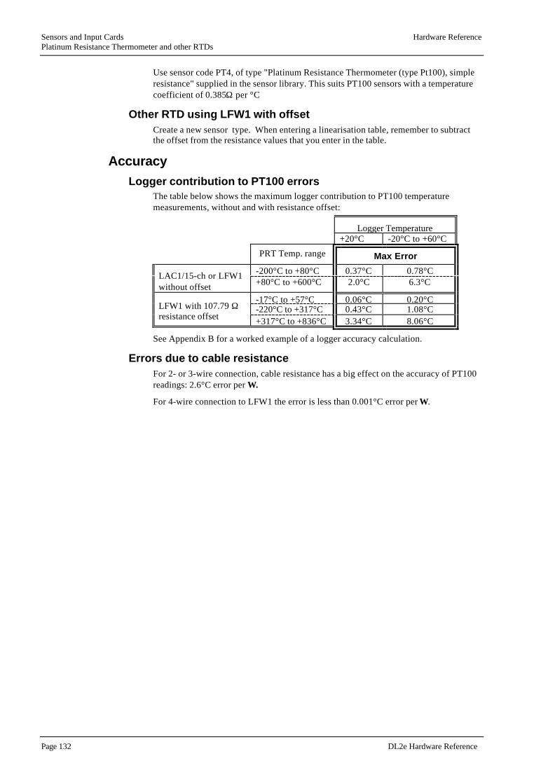
Sensors and Input Cards Hardware ReferencePlatinum Resistance Thermometer and other RTDs
Page 132 DL2e Hardware Reference
Use sensor code PT4, of type "Platinum Resistance Thermometer (type Pt100), simpleresistance" supplied in the sensor library. This suits PT100 sensors with a temperaturecoefficient of 0.385Ω per °C
Other RTD using LFW1 with offsetCreate a new sensor type. When entering a linearisation table, remember to subtractthe offset from the resistance values that you enter in the table.
AccuracyLogger contribution to PT100 errors
The table below shows the maximum logger contribution to PT100 temperaturemeasurements, without and with resistance offset:
Logger Temperature+20°C -20°C to +60°C
PRT Temp. range Max Error
-200°C to +80°C 0.37°C 0.78°CLAC1/15-ch or LFW1without offset +80°C to +600°C 2.0°C 6.3°C
-17°C to +57°C 0.06°C 0.20°C-220°C to +317°C 0.43°C 1.08°CLFW1 with 107.79 Ω
resistance offset +317°C to +836°C 3.34°C 8.06°C
See Appendix B for a worked example of a logger accuracy calculation.
Errors due to cable resistanceFor 2- or 3-wire connection, cable resistance has a big effect on the accuracy of PT100readings: 2.6°C error per Ω .
For 4-wire connection to LFW1 the error is less than 0.001°C error per Ω .

Hardware Reference Sensors and Input CardsThermocouples
DL2e Hardware Reference Page 133
ThermocouplesThermocouples are sensors that generate a voltage output. They comprise a junction oftwo dissimilar metals, e.g. copper/constantan.
The thermocouple’s output voltage depends on the pair of metals used, and is roughlyproportional to the temperature difference between the thermocouple junction and acold junction. Thermocouple cable is made of the thermocouple materials, and the coldjunction is the point at which the thermocouple cable terminates in a connection tomeasuring instrument, or a junction box.
To obtain an absolute temperature reading, the temperature of the cold junction has tobe measured and added to the temperature difference derived from the thermocouplevoltage. The logger can perform this calculation, which is known as ‘cold junctioncompensation’ or ‘cold junction referencing’.
The logger’s terminal panel is designed to be isothermal (i.e. all terminals held at thesame temperature). It has a thermistor mounted on it to measure its temperature. Thethermistor can be optionally switched into channel 1 to provide a cold junctiontemperature for thermocouple measurements.
Thermocouples are small and rugged, some capable of measuring temperatures inexcess of 1000 °C. Because they are derived from voltages, thermocouplemeasurements are not adversely affected by cable resistance, but long lengths ofunscreened cable may pick up electrical noise which can cause errors.
Disadvantages are that the sensors themselves are not very accurate (see below) andadditional errors arise from measurement of the cold-junction temperature. Their outputfor small temperature differences is low, typically 30 to 40 µV per °C. The logger’svoltage offset can therefore cause an error amounting to a significant fraction of a °C.
AccuracyTypical errors of common thermocouples, measuring -20°C to +60°C:
Thermocouple Error
Class 1 types J, K 1.5°C
Class 1 type T 0.5°C
Using thermocouples with the DL2e loggerSetting up
Sensor connectionsSingle-ended voltage connection is suitable for many applications, but bear in mind thefollowing points:
• A large offset (typically 20µV) is possible on LAC1 voltage measurements in 30-ch mode, corresponding to errors of 0.5 °C or more. Use LAC1 in 15-ch mode ifthis is unacceptable.
• Beware of creating earth loops. In particular, avoid bare sensors in contact withmetalwork or conducting substances such as water. If unavoidable, use fullyfloating connections, but beware of common mode problems (sees "Earth loops"on page 95 and "Common mode voltages" on page 96).
• In electrically noisy conditions, noise rejection can be achieved by using screenedthermocouple cable and earthing it to the logger, or by earthing the sensor or fittingbias resistors (see "Voltage, differential" on page 89 for details).

Sensors and Input Cards Hardware ReferenceThermocouples
Page 134 DL2e Hardware Reference
Cold junction compensation• Use the on-board cold junction thermistor switched into channel 1.
• LAC1 should be set to 15-ch mode for better accuracy, but can be set to 30-chmode if reduced accuracy is acceptable.
IsothermalityThe logger’s terminal panel is designed to be isothermal under stable conditions of use.
• Avoid situations that can cause temperature differences to develop across theterminal panel, resulting in cold junction errors. For example:
> Thermocouple cables, warmed by exposure to direct sunlight or other heatsources, can conduct heat into the terminal panel.
> Rapid change in the logger’s temperature, e.g. moving it from a cold to awarm place, can cause uneven warming or cooling of the terminal panel.
Programming the loggerJ, K, T type thermocouples
The logger has resident linearisation tables spanning the range -120°C to +200°C for J,K, and T type thermocouples.
• Use the corresponding sensor codes TCJ, TCK, TCT respectively. The tables arelisted in Appendix E.
Other thermocouple types• Create a new sensor code and enter a linearisation table. Note that the table must
include the expected cold-junction temperature to enable the logger to performcold-junction compensation calculations.
Cold junction compensation• Program the cold junction channel before the thermocouple channel itself:
> On-board thermistor: specify sensor code TM1 for channel 1.
> Other cold junction channel: program a channel as a temperature-measuringchannel. Note that the logger requires cold junction channels to be linearisedchannels, expecting an RTD or thermistor, but not another thermocouple.
• Leave the cold junction channel with no sampling interval if you are not interestedin logging the cold junction temperature itself. Then enter the cold junction channelnumber for the thermocouple channel.

Hardware Reference Sensors and Input CardsThermocouples
DL2e Hardware Reference Page 135
AccuracyAs mentioned above, thermocouples in themselves are not very accurate. There arefurther contributions from cold junction temperature error, as a result of non-isothermality, and from logger input offset voltages.
Logger contribution to thermocouple errorsThe tables below show the errors arising from the logger’s measurement ofthermocouple voltages:
Maximum logger contribution to thermocouple errors (uncompensated)
Measurement range: -20°C to +60°C -120°C to +200°C
Logger temperature: 20°C -20°C to+60°C
20°C -20°C to+60°C
Logger Error
type J 0.27°C 0.42°C 0.95°C 2.09°C
type K 0.25°C 0.54°C 1.79°C 2.85°C
Thermocouple
type T 0.36°C 0.55°C 0.80°C 1.76°C
A cold junction measurement error has to be added to these figures:
Loggertemperature:
20°C -20°C to +60°C
Thermistor contribution 0.1°C 0.13°C
Logger contribution 0.14°C 0.17°C
Maximum total 0.24°C 0.30°C

Appendices
Page 136 DL2e Hardware Reference
Appendices

Appendices
DL2e Hardware Reference Page 137

Appendix A : DL2e Technical Specifications Appendices
Page 138 DL2e Hardware Reference
Appendix A : DL2e Technical Specifications
Logging
Logging interval and speed1, 5, 10, 30 sec, 1, 5, 10, 30 min, or 1, 2, 4, 12 or 24 hours, programmable for eachchannel. Readings can also be reduced to averages, maxima or minima at theseintervals. Typically 10 channels/sec.
Input channels60 Channels maximum, depending on the number and type of input cards installed, plus2 resident digital inputs and 2 relay outputs.
Analogue inputs
Analogue Card, LAC1Each LAC1 multiplexer card can select analogue inputs from:Either: 15 channels of differential voltages and 3-wire resistancesOr: 30 channels of single-ended voltages and 2-wire resistances.
It directly measures voltages up to ±2V or resistances <1MΩ .Voltages up to ±50V and currents can be measured using attenuator resistors, mountedon the input screw terminals or on an LPR1 or LPR1V card.
Analogue Card, ACD1Each ACD1 card can select analogue inputs from 15 channels of differential voltagesand 3-wire resistances.
It directly measures voltages up to ±2Vdc, 2Vac rms, or resistances <1MΩ .
4-Wire Card, LFW1Each LFW1 card can select up to 12 bridge, potentiometric, differential voltage, or 2-or 4-wire resistance sensors.4-wire resistance measurements virtually eliminate cable resistance errors.
PT100 platinum resistance thermometers, (e.g. DIN 43760/BS1904 type)are measured over -200°C to + 850°C.In the -17°C to +57 °C range of logger and PT100 temperature, 0.01°C resolution and0.2°C accuracy is obtained.

Appendices Appendix A : DL2e Technical Specifications
DL2e Hardware Reference Page 139
Voltage source1.0486V to approx. 4V, adjustable, 60mA max per group of 6 channels.Output impedance < 0.5ΩTemperature coefficient < 50ppm/ °C1.0486V repeatability < 0.5mV
DC Voltage readings via LAC1, ACD1 or LFW1
12 bit + sign. 4 Ranges, user-selected or autoranged:
Range Full Scale Resolution
1 ±4mV 1µV
2 ±32mV 8µV
3 ±262mV 64µV
4 ±2.097V 0.5mV
ErrorsMaximum values shown with typical figures in brackets:
Logger Temperature 20 °C -20 °C to 60 °C
Full scale error ±0.07% (0.04%) ±0.02% (0.1%)
Long term stability ±0.25% (0.02%) over 1 year
Differential Offset ±10 µV (3µV), ±0.02% ±12 µV, ±0.02%
Noise 0.2µV RMS
Input Impedance approximately 100 MΩ
Common Mode Range ±2V ( or ±1.05V if + input closer to logger 0V than - input)
Common Mode Rejection ratio 140 dB typical, on voltage range 1
AC Voltage readings via ACD112 bit + sign. 4 Ranges, user-selected or autoranged:
Input type and frequency Input Level (mV ac rms) Accuracy
Sinusoidal signals45 to 60 Hz-20 to + 60 °C
0 to 1010 to 5050 to 100100 to 2000
Zero reading in this range±3mV±0.6 % of reading ±0.25mV±0.6% of reading
Sinusoidal signals65 to 1000 Hz
10 to 2000 Maximum additional error±0.5% of reading.
Non-sinusoidal signalsCrest factor 1.0 to 1.7(square or triangular wave)
10 to 2000 Maximum additional error±1.0% of reading
Common mode rejection at dcup to 1kHz
0.1% ( = 65dB )0.5% ( = 45db )

Appendix A : DL2e Technical Specifications Appendices
Page 140 DL2e Hardware Reference
Resistance readings dc via LAC1, ACD1 or LFW1Autoranging 12 bit voltage readings with programmable 2, 20, 200 or 2000µAexcitation, giving 1MΩ full-scale or <0.01Ω resolution.
AccuracyAs voltage readings, with additional errors:
Logger Temperature 20°C -20 to +60 °C
2 µA current ±0.3% full scale ±0.6% (to + 50°C)
Other currents ±0.05% ±0.1%
2-Wire LAC1 only ±20Ω ( 6Ω typical) additional offset.
See also Appendix B.
Resistance readings acUsing ac excitation card type ACS1 & ACD1.
AccuracyOverall system accuracy ±2% for R= 500 to 30,000 Ohms.
Input protectionAnalogue inputs withstand ±15V continuously, and much higher voltages in briefpulses. For additional protection, see LPR1V below.
Attenuator Card, LPR1For use with LAC1 Analogue Card only.Provides sockets for signal conditioning resistors for 30 channels.Resistor positions may be left vacant or resistors fitted in shunt or dividerconfiguration, respectively for measuring currents up to 0.1 Amp or voltages up to±50V.
Input Protection Card, LPR1VConnects transient-absorbing varistors to 30 LAC1 Analogue Card inputs, or 12 LFW14-Wire Card inputs, for additional input protection.
Also provides socketted resistor positions for signal conditioning, (only suitable for thisapplication when used with LAC1 - see LPR1 above). Avoid using LPR1V whenmeasuring resistances >100KΩ , as varistor leakage currents may be a source ofsignificant error.

Appendices Appendix A : DL2e Technical Specifications
DL2e Hardware Reference Page 141
Digital inputs and outputs
Digital inputsAll DL2e's have 2 resident 16-bit counter channels that can continuously monitor logiclevels or switch-closures, recording digital status, counts or frequency (up to 100Hz), orcan trigger special logging sequences.
Relay outputs2 SPDT relays for powering up sensors, or providing alarms or malfunction warnings. 1Amp, 50 V contact rating.
Counter Card, DLC1Each DLC1 card provides up to 15 extra 16-bit counter or frequency channels.Maximum frequency: 500Hz/1ms pulse for switch closures, 500kHz for 5V logic levelsignals (see page 117 for details). Each channel can log up to 65,472 counts betweenscans.

Appendix A : DL2e Technical Specifications Appendices
Page 142 DL2e Hardware Reference
Other specifications
ProcessingThe logger can convert readings into engineering units using linearisation tables or aconversion factor and zero offset. User-expandable sensor library includes Delta-Tsensors, Platinum Resistance Thermometers, Thermistors (Fenwal 2K, 2K252, 10K and100K types) and Thermocouples (types J, K and T). Cold junction temperaturemeasured at isothermal terminals.
For thermistor errors see also page 129.For Platinum Resistance Thermometer errors see page 132.For Thermocouple errors see page 133.
DisplayA 2 line LCD shows instantaneous output from any sensor (in engineering units), time,battery and memory condition, and status messages, without disturbing logging.
MemoryHighly reliable 2 battery-backed RAM.Expandable from 64K to 128K timed readings.Automatic RAM check.
Data formatASCII, easily loaded into spreadsheets and other popular software, such as Excel etc.Transmitted readings are date/time stamped, labelled in engineering units with errorsflagged.Data files, created by the Ls2Win, are comma separated.
InterfaceRS232 Serial interface up to 9600 Baud.Up to 10,000 readings transferred per minute (without disturbing logging).
Computers & SoftwareThe logger Windows software LS2Win enables a PC to communicate with the logger,edit logging programs and collect accumulated data.
To operate the logger from your PC you need the following:
• A PC running Windows 95, 98, 2000 or NT4.0 Service Pack 4, or later.
• One free RS232 serial port.
• CD-ROM drive (required for installation.
• at least 16M RAM memory and 5M of hard disk space.
• Logger-PC RS232 cable: Type LRS1 available from Delta-T, or you can make oneup. See "Communications cables" on page 51.
• Ls2Win distribution disk.
Power6 internal AA alkaline cells provide power for 500K readings, or 24 hours ofkeypad/LCD or RS232 interface operation. The internal lithium cell will retain memoryfor 2 months in the event of a power supply failure.

Appendices Appendix A : DL2e Technical Specifications
DL2e Hardware Reference Page 143
EnvironmentalOperating temperature: -20°C to +60°C. IP65 weatherproof case with desiccant andhumidity indicator.
Dimensions and weightSize: 280 x 220 x 140 mm, Weight: 2.7kg.
Rechargeable battery pack LBK1
Battery typeDryfit A200, or equivalent, sealed lead-acid with thixotropic electrolyte gel.
Voltage12V nominal; 12.6 - 12.9V fully charged, 10.5V fully discharged at 20°C.
Capacity1.8Ah nominal, sufficient for 36 hours operation awake, or 1 year asleep at 20°C (lessat higher temperatures).
Charging conditions16 hours at constant voltage, which is temperature dependent:13.98V ±0.18V at 15°C13.80V ±0.18V at 20°C13.65V ±0.18V at 25°C.
Important: do not exceed the specified charging voltage.
Fuse1 Amp, 20x5mm cartridge fuse
SealingIP65
Dimensions & Weight220 x 85 x 85 mm, 1kg
Electro-Magnetic CompatibilityThe DL2e logger has been assessed under the European Union EMC Directive89/336/EEC, and conforms with the following harmonised emissions and immunitystandards:
EN 50081-1 : 1992EN 50082-1 : 1992

Appendix B : Accuracy of logger readings Appendices
Page 144 DL2e Hardware Reference
Appendix B : Accuracy of logger readingsThere are several categories of error that should be considered when estimating theaccuracy of logger readings:
Analogue errors:These are due to the inherent limitations of the electronic components used in thelogger.
Arithmetic errors:These are due to the approximations made by the logger when it performs calculationsand stores data.These logger errors are discussed in detail below.
In addition to the logger’s contribution, errors can be attributed to other sources:
Sensor errors:These depend on the inherent accuracy of a sensor, as specified by the manufacturer.
Sampling errors:(1) These can be caused when a sensor is subject to influences that distort measurementof the desired parameter, for example poor shielding of an air temperature sensor inbright sunlight. These errors can be minimised by careful attention to sensorinstallation.
(2) These can be caused when readings of a fluctuating parameter are not loggedfrequently enough to build up an accurate picture of how it varies.
Cabling errors:Cable resistance can cause significant errors when measuring resistance sensors.Techniques for minimising the effects of cable resistance are discussed in"2-, 3- and 4-wire connection schemes" on page 63),Thermistors: "Errors due to cable resistance" on page 129, andPlatinum Resistance Thermometers: "Errors due to cable resistance" on page 132.
Adding errors from different sourcesThe logger specification in Appendix A quotes maximum and typical accuracy figuresfor the logger.
The accuracy calculations in this section, and the figures quoted in the temperaturemeasurement section, are derived by adding together maximum error figures. Thisprocedure gives an absolute, worst-case, accuracy figure, which would result if all theerror sources conspired to act in the same direction.
In practice, worst case errors of this magnitude are unlikely to occur. A more realisticestimate of likely errors can be obtained by calculating the ‘root mean square’ ofindependent error contributions, i.e. calculate the square of each error, add them up andtake the square root.

Appendices Appendix B : Accuracy of logger readings
DL2e Hardware Reference Page 145
Analogue accuracy
Voltage reading accuracyThe logger reads voltage on 4 ranges, normally auto-ranged:
Range FullScale
Resolution
1 ±4mV 1µV
2 ±32mV 8µV
3 ±262mV 64µV
4 ±2.097V 0.5mV
The key voltage reading accuracy specifications are given below, ( maximum valueswith typical figures in brackets)
LoggerTemperature:
20°C -20 to +60°C
Full scale error ±0.07% (0.04%) ±0.2% (0.1%)
Long term stability ±0.25% (.02%) over 1 year
Differential Offset ±10µV (3µV), ±0.02% ±12µV, ±0.02%
Noise 0.2µV RMS
Input Impedance approximately 100 MΩ
Common Mode Range ±2V (or ±1.05V if + input is closer to logger0V than –input)
Near the full scale of each range of a recently calibrated logger, the maximum error isthe Full Scale Error .
At the lower end of each scale the errors are dominated by the Resolution plus theDifferential Offset.
EXAMPLEWhen reading a 2 Volt input with the logger at 60°C:
• Maximum error is 2V x 0.2% = 0.004V = 4mV
When reading 5mV with the logger at 20°C:
• Resolution is 8µV, on voltage range 2
• Differential offset is 10µV
• Maximum error is 8µV + 10µV = 18µV.
Note that:
• The differential offset is only specified for differential voltage readings. Single-ended voltage readings may have much larger offsets, typically 20µV.
• There is a 10% hysteresis band between voltage ranges, to prevent the loggerchanging voltage ranges too frequently: this means that voltages in the upper 10%of each voltage range may be read with a resolution corresponding the next highestrange.

Appendix B : Accuracy of logger readings Appendices
Page 146 DL2e Hardware Reference
Other voltage reading error sources are:
Error source Specification Comment
Long termstability
±0.25% max. (0.02% typical)over 1 year
a small typical error
Noise 0.2µV RMS negligible
Input Impedance approx. 100 MΩ negligible for source inputimpedance <10kΩ
Common ModeRange
±2V (or ±1.05V if logger’s +input is nearer to logger’searth than the - input)
the average of the inputvoltages must be within theCommon Mode Range
Resistance reading accuracyThe following additional errors apply to resistance readings:
LoggerTemperature:
20°C -20 to +60°C
2µA current ±0.3% full scale ±0.6% (to +50°C)
Other currents ±0.05% ±0.1%
2-Wire LAC1 only ±20Ω (6Ω typical)
To calculate the error in a resistance reading:• First calculate the voltage the logger sees when the chosen excitation current is
applied to the resistor ( V = Iexc ×R ), determine the voltage error as above, andconvert it back to a resistance error :
Rerror = Verror / Iexc
• Add the additional resistance reading error(s) from the table above. Note theadditional error inherent in 2-wire resistance measurements.
Example:Taking a 4-wire reading of 1000Ω with the logger at room temperature, using 2000µAexcitation current:
Voltage contributionThe logger will be measuring a voltage of 1000Ω x 2000µA = 2VThe maximum error will be 2V x 0.07% =1.4mVexpressed in Ω , this will be 1.4mV / 2000µA = 0.7Ω
Resistance contributionResistance contribution = 1000Ω x 0.05% = 0.5Ω
Total maximum error = 0.7Ω + 0.5Ω = 1.2Ω

Appendices Appendix B : Accuracy of logger readings
DL2e Hardware Reference Page 147
Calculation of logger analogue accuracy: a workedexample
This example shows how to calculate the maximum logger error when measuring atemperature in the region of 20°C using a 2K thermistor, 2-wire connection to a LAC1in 30-ch mode, measured as sensor type TM1, with the logger at 20°C.
1. Determine the resistance measured by the logger
• Using the table on page " on page 153, the resistance at 20°C is 2.498kΩ .
2. Calculate the corresponding voltage measured by the logger
• From the sensor characteristics of the standard sensors, the excitation current forsensor type TM1 is 20µA
• Using V = I x R, the voltage measured by the logger is(2.498 x 103)Ω x (20 x 10-6)A = 0.04996 V = 49.96mV
3. Calculate the voltage measurement error
• The voltage is measured on range 3, so resolution is 64µV
• Differential offset is 10µV (logger at 20°C)
• The % reading error at 49.96mV is0.07% x 49.96mV = 0.035mV = 35µV.
Resolution plus voltage offset ( 64µV + 10µV = 74µV ) is greater than % error, so take74µV as the voltage measurement error.
4. Convert voltage measurement error into resistance (R = V / I)
• Using R = V / I, error in measured resistance is 74µV / 20µA = 3.7Ω
5. Calculate additional resistance reading errors
• for 20µA excitation current: 0.05% x 2.498 x 10³Ω = 1.25Ω
• for 2-wire resistance measurements: 20Ω .
6. Combined worst case resistance reading error is:
3.7Ω + 1.25Ω + 20Ω = 24.95Ω
8. Convert the resistance reading error into a temperature
• Using the table on page 153, the resistances at 22.5°C and 17.5°C are 2.234 kΩand 2.800 kΩ .
• The change in resistance over a 5°C change in temperature is
2.800 kΩ - 2.234 kΩ = 0.566 kΩ = 566 Ω
• The change in temperature for 1°C temperature change is
566Ω / 5 = 113.2Ω
• 24.95Ω resistance reading error corresponds to a temperature error of
24.95Ω / 113.2Ω = 0.22°C
Answer: the maximum logger error is 0.22°C.

Appendix B : Accuracy of logger readings Appendices
Page 148 DL2e Hardware Reference
Arithmetic accuracy
Analogue sensors: linear conversion to engineeringunits
The logger stores readings from analogue sensors as raw data with no additional loss ofaccuracy (other than the analogue errors described above). Ls2Win converts these rawdata to engineering units, and presents readings with a sufficient number of decimalplaces to represent each resolution step.
The maximum rounding error that can occur is just less than one resolution step.
Counter and frequency sensors: linear conversion toengineering units
RoundingThe logger stores readings as a number of counts, with large numbers of counts beingrounded to the multiples of 8 or 64:
Number of counts Resolution
0 to 4095 1
4096 to 32760 8
32768 to 65472 64
Resolution of frequency readingsThe frequency represented by each stored count, and hence the resolution of frequencychannels, depends on the length of the sampling interval. For example:
Sampling interval Resolution
1 s 1 Hz
10 s 0.1 Hz
1 minute 0.0167 Hz (1/60Hz)

Appendices Appendix B : Accuracy of logger readings
DL2e Hardware Reference Page 149
Linearisation errorsThe logger calculates engineering unit values from linearisation tables by linearinterpolation, i.e. it treats each segment of a linearisation curve as a straight line. Theerror due to this is as illustrated below:
Figure B-1 : Error due to linear interpolation
Once linearised, the stored data is rounded to a resolution that depends on themagnitude of the deviation of the reading from the zero offset.
Rounding errors for linearised data (in engineering units):
Deviation from offset Resolution
0 to 40.95 0.01
40.96 to 327.6 0.08
327.68 to 2620.8 0.64
2621.44 to 20966.4 5.12
For example, for sensor code PT4, a resolution of 0.01°C is available over theenvironmental temperature range of 20°C ±40.95°C (i.e. -20°C to +60°C).

Appendix C: Calculating the speed of data readings Appendices
Page 150 DL2e Hardware Reference
Appendix C: Calculating the speed of datareadings
The time it takes for the logger to complete one cycle of readings (a scan) is made up ofthe scan overheads at the start and end of each cycle, plus the time taken for each of thevarious channel readings in the scan, and their associated processing functions.
In most applications where channels are to be sampled at less than about 3 readings persecond, you will not need to take into consideration the time it takes for the logger toservice the scan.
The following table and notes provide information on how to calculate the time it takesfor the logger to service individual readings, and the complete scan, in applicationswhere:
• the scan involves taking readings more frequently than 3 times per second.
• many channels of widely differing readings that require frequent and unpredictableautoranging are to be logged.
• many channels require processing and/or compression of data prior to storage.
Time taken servicing a LOG or EVENT (msec)
SCAN OVERHEADS[1] Awake Asleep
Start of scan 80 250
End of scan 200 200
SERVICING TIMES PER READING
Digital Reading 65
Zero Full scale
Analogue Reading [2], [3] 41 80
Ranging down Ranging up
extra for autoranging [4] 40 per range 80 + 80 per range
LAC1 30-ch moderesistance
All other analoguechannel types
extra for autozero [5] (peranalogue reading type per
terminal group)
60 41
Extra for processing
linearisation 17
cold junction referencing [6] 32 (extra tolinearisation)
STORAGE TO MEMORY Storing a singlereading
Calculating andstoring an average
10 26

Appendices Appendix C: Calculating the speed of data readings
DL2e Hardware Reference Page 151
NOTES:[1] SCAN OVERHEADS is the time taken for the logger to prepare for taking readingsat the beginning of a LOG or EVENT, and performing ‘housekeeping’ calculationswhen finished.
[2] The time required for an analogue reading depends on the magnitude of the inputsignal. ‘Full scale’ is with respect to the voltage range being used. If autoranging, thefull scale figure applies for inputs of 4mV, 32mV, 262mV, 2.048V, and forcorresponding resistance values (Vin= R x Iexcitation).
[3] The timings quoted above apply for the 50/60 switch set to the European mainsfrequency, 50Hz. When set to 60Hz, all analogue timings are approximately 20% faster(see "Electrical mains environment" on page 48).
[4] Autoranging to a less sensitive range is slower than to a more sensitive range, andrequires an over-range recovery cycle in addition to the reading being taken.
[5] The logger takes separate autozero readings for each terminal group, for voltage andresistance readings at each excitation current, as required for a LOG or EVENT. Youcan minimise autozero overheads for mixed resistance readings by grouping channelsthat use the same excitation current on consecutive input channels in the same terminalgroup.
EXAMPLES: two autozero readings are required for channels 1 to 30 programmed asVLT channels: 5 autozero readings are required for channels 1 to 6 programmed asTM1, RR1, RR2, RR3, RR4, VLT, as in the DEFAULT configuration.
[6] The logger takes a single cold junction reading for any number of thermocouplemeasurements in a single scan.

Appendix D : Resident linearisation tables Appendices
Page 152 DL2e Hardware Reference
Appendix D : Resident linearisation tablesThe following pages set out the conversion tables that the logger uses to determinetemperature values from measurements taken using the various thermistor,thermocouple and PRT sensors the Logger can handle.

Appendices Appendix D : Resident linearisation tables
DL2e Hardware Reference Page 153
Thermistor tablesTemp (°C) Resistance (kΩ) for sensor code and thermistor type:
TM1 (2K)Fenwal UUA32J2
TM2 (2K252)Fenwal UUA32J3
TM3 (10K)Fenwal UUA41J1
TM4 (100K)Fenwal UUT51J1
60.0 0.49760 0.56025 2.48780 22.5900
57.5 0.54490 0.61355 2.72450 24.9025
55.0 0.59720 0.67245 2.98610 27.4750
52.5 0.65570 0.73830 3.27840 30.3660
50.0 0.72060 0.81125 3.60230 33.5910
47.5 0.79300 0.89295 3.96510 37.2265
45.0 0.87400 0.98375 4.36840 41.2920
42.5 0.96440 1.08580 4.82140 45.8900
40.0 1.06540 1.19950 5.32640 51.0480
37.5 1.17940 1.32765 5.89530 56.8980
35.0 1.30600 1.47090 6.53140 63.4800
32.5 1.45000 1.63280 7.25045 70.9700
30.0 1.61140 1.81140 8.05680 79.4220
27.5 1.79440 2.02035 8.97120 89.0740
25.0 2.00000 2.25200 10.00000 100.0000
22.5 2.23400 2.51560 11.17050 112.5200
20.0 2.49800 2.81320 12.49200 126.7400
17.5 2.80000 3.15300 14.00100 143.0950
15.0 3.14200 3.53810 15.71100 161.7300
12.5 3.53400 3.97960 17.67150 183.2450
10.0 3.98000 4.48130 19.89900 207.8500
7.5 4.49300 5.05900 22.46450 236.3600
5.0 5.07800 5.71810 25.39100 269.0800
2.5 5.75500 6.48000 28.77450 307.1550
0.0 6.53000 7.35280 32.65000 351.0200
-2.5 7.43000 8.36640 37.15100 402.2750
-5.0 8.46600 9.53180 42.32600 461.5500
-7.5 9.67100 10.89050 48.35900 531.1000
-10.0 11.06600 12.45900 55.32600 611.8700
-12.5 12.69700 14.29700 63.48700 707.0600
-15.0 14.59000 16.42900 72.95100 818.0700
-17.5 16.81800 18.93700 84.09150 949.5050
-20.0 19.41400 21.86100 97.07200 n/a

Appendix D : Resident linearisation tables Appendices
Page 154 DL2e Hardware Reference
Thermocouple tablesTemp (°C)is the temperature difference between hot and cold junctions.
Temp (°C) Output (mV) for sensor code and thermocouple type:
TCJ, type J,(Iron/Constantan)
TCK, type K,(Chromel/Alumel)
TCT, type T,(Copper/Constantan)
-120 -5.426 -4.138 -3.923
-110 -5.036 -3.852 -3.656
-100 -4.632 -3.553 -3.378
-90 -4.215 -3.242 -3.089
-80 -3.785 -2.920 -2.788
-70 -3.344 -2.586 -2.475
-60 -2.892 -2.243 -2.152
-50 -2.431 -1.889 -1.819
-40 -1.960 -1.527 -1.475
-30 -1.481 -1.156 -1.121
-20 -0.995 -0.777 -0.757
-10 -0.501 -0.392 -0.383
0 0.000 0.000 0.000
10 0.507 0.397 0.391
20 1.019 0.798 0.789
30 1.536 1.203 1.196
40 2.058 1.611 1.611
50 2.585 2.022 2.035
60 3.115 2.436 2.465
70 3.649 2.850 2.908
80 4.186 3.266 3.357
90 4.725 3.681 3.813
100 5.268 4.095 4.277
110 5.812 4.508 4.749
120 6.359 4.919 5.227
130 6.907 5.327 5.712
140 7.457 5.733 6.204
150 8.008 6.137 6.702
160 8.560 6.539 7.207
170 9.113 6.939 7.718
180 9.667 7.338 8.235
190 10.222 7.737 8.757
200 10.777 8.137 9.286

Appendices
DL2e Hardware Reference Page 155
Appendix E : Identifying components on cardsTo identify component positions on a card relating to a specific input channel, refer tothe table below:
• debounce capacitors on a DLC1
• shunt and divider resistor positions on a LPR1 or LPR1V
Channel DLC1:debounce capacitor
LPR1 and LPR1V:shunt or divider positions
1, 16, 31, 46 1 1 or 16
2, 17, 32, 47 2 2 or 17
3, 18, 33, 48 3 3 or 18
4, 19, 34, 49 4 4 or 19
5, 20, 35, 50 5 5 or 20
6, 21, 36, 51 6 6 or 21
7, 22, 37, 52 7 7 or 22
8, 23, 38, 53 8 8 or 23
9, 24, 39, 54 9 9 or 24
10, 25, 40, 55 10 10 or 25
11, 26, 41, 56 11 11 or 26
12, 27, 42, 57 12 12 or 27
13, 28, 43, 58 13 13 or 28
14, 29, 44, 59 14 14 or 29
15, 30, 45, 60 15 15 or 30

Index
Page 156 DL2e Hardware Reference
Index
..BIN file format[BIN] 30.DAT file format[DAT] 31.HFD file format[HFD] 30.PRN file format[PRN] 31
115/30 switch 6915-ch mode 61, 69
22-wire
4-20mA transducer 125resistance 63, 101
330-ch mode 61, 693-wire
bridge 109resistance 63
3-wire bridge 1043-wire resistance 104
44-20mA transducer
2-wire 1254-wire
card, LFW1 75resistance 75
4-wire resistance 63, 106
550/60 switch 48, 151
66-wire bridge 109
AAC
card, ACD1 73
AC Excitation card, ACS1 83accuracy
analoguea worked example 147
Accuracy 1442-wire resistance measurement 1013-wire resistance 104AC Voltage 139analogue 145arithmetic 148current measurement 99DC Voltage 139digital channels 118effects of moisture 55PT100 measurement 132resistance 146Resistance 140resistance measurements 63thermistor measurement 129thermocouple 133thermocouple measurement 135voltage divider 93voltage measurement 145
accuracy: a worked example 147ACD1 61ACS1, AC excitation card 83ACS1, AC Excitation card 61Analogue
accuracy 145input card 61signal 60
analogue measurementsconnections 66
Anti-static precautions 49Asleep 9, 89Attenuator card, LPR1 80Auto-print 35
ending 35Autoranging
effect on logging speed 150Autosleep 10, 12
disabling 35Ave too large 25Awake 9
BBackup battery 42Bad cold jn. 25Battery
backup 42

Index
DL2e Hardware Reference Page 157
failure 24, 26, 41life 41, 55life expectancy 19low 41replacing 42voltage 19
Battery pack, rechargeable 46Baud rate 33, 50Baud rate selector switch 50Bias resistors 62, 89Bridge
3-wire 1096-wire 109bipolar 96common mode voltage 96completion resistor 109excitation voltage 96full 109half 109integral excitation 109quarter 63, 109
Bridge measurement 75, 109Bridge measurements 63Bytecount 36
CCable
communication 51logger-computer 52logger-printer 52
Cable resistancecompensating for error 101, 104effect on PT100 accuracy 132effect on thermistor accuracy 129minimising error 63
Calibration 57bridge 110resistance offset 76shunt resistor 98voltage divider 92
cards and on-board channels 65Channel
counter 22event trigger 23frequency 22on-board digital 115relay 121
Checksum 36Chips
installing 49Clock, setting the logger’s 18CLR (event trigger) 23Cold junction
compensation 133, 134on-board thermistor 101, 129
Cold junction compensation 134Coldboot 15Collecting data 30Common mode
range 96voltage 96
Communicationcable 51diagnosing faults 53parameters 33, 50
Computers & Software 142
config'n 20configuration 20Configuration
DEFAULT 15Contact Delta-T 59Contrast adjustment 49Counter 60, 115
resolution 148Counter card, DLC1 115Counter input 22Counting at high frequencies 117Current
excitation 108measurement 62, 80, 98
Current consumption 9
DData
collection 30erasing 30erasing (from the logger’s memory) 37event triggered 10follow-on 31integrity check 36starting.. 31, 34timed 10TIMED 30TRIG/61, 62 30type 30, 34, 38
Data bits 33, 50Data collection devices 36Data collection terminal 36Data file
size of 32Data trigger 60Date 18, 20
format 48DEFAULT configuration 15Deleting malfunction reports 26Desiccant 55
regeneration 56Diagnosing communication faults 53Differential voltage 69, 73, 75Differential voltage measurement 61, 89Digital
input 115signals 60status 60
Digital status 115, 120DIP switch 48, 50Disk drive 36Display (contrast) 49DL2 Control Panel 19, 22
Logger 19Sensors panel 22
DLC1, counter card 115DOWN function 33d-trigger 23
EEarth
loops 62Earth loop 95Echo test 53Electrical

Index
Page 158 DL2e Hardware Reference
induced noise 62noisy environment 62, 89
Electrical mains frequency 48Electro-Magnetic Compatibility 143Ending auto-print 35, 37Erase data up to 38Erasing data 30Error 12, 22, 24
cable resistance 63DL2 Control Panel 12, 22, 24PT100 132thermistor measurement 129
Event 60EVENT 9, 10, 23Event trigger
channel 23-ed data 10-ed start logging 27, 28testing 24
Excitationcurrent 108voltage 75
External power supply 43
FFenwal Unicurve 129Fenwal Unicurve thermistors 129Field installation 55File
format 30Flags 25Follow-on
data 31Format 34
data file 30Frequency 60, 115
resolution 148Frequency input 22Full bridge 109Fully floating sensor connection 89Function
DOWN 33keypad 12, 13PRINT 13, 33READ 13, 23s 14SET TIME 13, 18START 13, 28, 29t 14WAKE 13, 21
Fuse (rech. battery pack) 48
GGeneral Status Report 19
HHalf bridge 109Handshaking 33, 36heating effect
of excitation current 108high frequencies
counting at 117Humidity
protection against 55Humidity indicator 55
IIC
installing 49Immediate start 27, 28Impedance, input 86, 89Inactive source 34Induced electrical noise 62Input
impedance 86, 89Input card 67
AC, ACD1 73ACD1 61analogue 61installing 67LAC1 61LFW1 61standard analogue, LAC1 69
Input protectioncard, LPR1V 61, 80LAC1 70LFW1 75
InstallationIC’s 49in the field 55
Intermittent logging 126INTERNAL 41INTL 41
JJ, K, T type thermocouples 134
KK 21Keypad functions 12, 13Keypad main menu 12
LLAC1 61, 69
30-ch mode 63LBK1 46
storage 57Leap year 18Leap years 20LFW1 61Linearisation
errors 149Lithium cell 42, 57LOG 9, 10, 24, 26, 28Logger status 19Logging 10, 27
intermittent 126speed 150started 20stopped 21stopping 29
logging program 20Logic level signals 120LPR1, attenuator card 61, 80LPR1V, input protection card 61, 80

Index
DL2e Hardware Reference Page 159
MMain circuit board layout 40Main menu
keypad 12Maintenance 57Malfunction
deleting reports 26sensor 25warning relay 24, 25warning relay, resetting 26
Maximum valuein data file header 26
Memorycheck 15filled 26full 25IC, installing 49status 21
Minimum valuein data file header 26
Moistureeffect on measurement accuracy 55protection against 55
NNoise
induced electrical 62Noisy 25
electrical environment 62, 89Number of data 34
Oo/s limits 26Offset
applied to resistance measurements 106On-board
digital channel 115relay channel 121
Outside limit 25Outside table 25Over-range 25Over-run 11, 24, 26, 118Overwrite mode 15, 21
PParity 33, 50Password 17Platinum resistance thermometer 106, 131
3-wire 1114-wire 106
Potentiometric measurement 63, 75, 113power supply
external 19Power supply 41
backup 42cable 43external 43failure 43selector switch 41
power supply 0V schematic 45Powering sensors 24, 64, 121, 123Preset time start 27
PRINT 13PRINT function 33Printer
checking operation 33outputting data directly to 33
Priority tasks 10conflicting 11
PROMinstalling 49version 19
PT100 106, 1313-wire 1114-wire 106
Pulse count 115
QQuarter bridge 63, 109
RR/PRT switch 76RAM
check 15chip, installing 49
RAM STATUS 21Reachargeable battery pack
storage 57READ function 13, 23Recalibration 57Rechargeable battery pack 46Rechargeable battery pack LBK1
sspecifications 143Channel 22Relay
channel 121checking operation 123fuses 122warm-up 22, 121
Relay channel 22relay channels
excercising 24Reset
cold (coldboot) 15warm 16
resistance2-wire 70
Resistanceaccuracy 146
Resistance measurement 62, 69, 73, 752-wire 1013-wire 69, 73, 1044-wire 75, 106small changes 63using LFW1 76with offset 63, 75, 106
Resistance offsetcalibration 76
Resistance temperature detector (RTD) 131Resistor
bridge completion 109shunt 80, 98voltage divider 80, 92
Resolutionlagged data 26
Ribbon cablesfitting and removing 68

Index
Page 160 DL2e Hardware Reference
RS232cable 51
RS232 portconfiguration 51
RTD 131
Ss function 14Sampling errors 144Sensor
bipolar output 96errors 144malfunction 25powering 24
Sensor connection2-wire resistance 1013-wire resistance 1044-wire resistance 106bridge 109current 98differential voltage 89fully floating 89potentiometric 113PT100 and RTD’s 131single-ended voltage 86thermistor 128thermocouple 133
sensor connectionsrelays 124
Sensor connectionsdifferential voltage 61single-ended voltage 61
sensor connections: relays 124Sensors status 22Service and Spares 58SET (event trigger) 23SET TIME function 13, 18Setup string
for PRINT 15Shunt
resistor 80Shunt resistor 98Signal
analogue 60digital 60low level voltage 62
Single-endedvoltage 75
Single-ended voltage 70Single-ended voltage measurement 61, 86Size (of data files) 32Sleep 9, 12, 86, 89Specifications 138Speed of data readings 150Standing by 20Start
immediate 27START function 13, 28, 29Start trigger 60Start trigger set 28starting logging
immediate 28Starting logging 27
event triggered 27, 28immediate 27preset time 27
Statusdigital 60, 115, 120memory 21RAM 21
STOPinternal stop button 29
Stop bits 50Stopping logging 29Storage 57STORED DATA 21s-trigger 23Sunlight
effects on logger 55Supplementary card 61, 67Switch
15/30 6950/60 48, 151baud rate selector 50DIP 48, 50power supply selector 41R/PRT 76
Tt function 14tables 152
resident sensor linearisation tables 152Technical support 59Temperature
effects on logger performance 55Terminal compartment
assembly for field installation 55Terminal mode 53Terms and Conditions of Sale 58Thermistor 128
on-board cold junction 129Thermistor tables 152Thermocouple 133
in field installations 55tables 152
thermocouple errors 135Thermsistor
on-board cold junction 101Time 18, 20TIMED
data 30Timed data 10TIMED RAM 21TRIG/61, /62
data 30RAM 21
Troubleshooting 34Printer 34
VVoltage
common mode 96divider resistor 92divider resistors 80excitation 75normal mode 96source on LFW1 78
Voltage measurement 61accuracy 145differential 69, 73, 75, 89differential, using LFW1 76

Index
DL2e Hardware Reference Page 161
resolution 145single-ended 70, 75, 86up to 50V DC 80, 92
WWake 9WAKE function 13, 21Warm reset 16WARM-UP 9, 10, 24
Warm-up relay 22, 24, 121Malfunction 25WARNINGS 44, 48Warranty and Service 58Wind vane 113
XXON/XOFF 36