dkm-409 pro at - datakom · dkm-409 pro at user manual rev_02 firmware v-2.5 dkm-409 pro at network...
TRANSCRIPT

DKM-409 Pro AT User Manual Rev_02 Firmware V-2.5
DKM-409
PRO AT
NETWORK
ANALYSER
The DKM-409-Pro-At is a precision instrument designed for displaying, logging and remote monitoring various AC parameters in a 3-phase network.
The power supply of the unit is isolated. The standard supply range is 100-265V-AC and 88-400V-DC allowing universal use in AC and DC systems.
The unit has 3 x 4-20mA analog outputs. Any measurement can be output as analog value.
The unit has 4 digital inputs and 2 relay outputs with programmable functionality, selected from a list.
Thanks to its isolated RS-485 Modbus RTU comport, the device is free from ground potential difference issues and data are safely transferred to automation and monitoring systems.
The device has 1MB internal memory for the record of all electrical parameters with required frequency. Records are read through Modbus.
The graphic screen allows display of waveforms and harmonic analysis graphs.
The user configurable screen where any measured parameter set can be displayed, transforms the unit to a custom designed measurement panel.
Ph-N and Ph-Ph volts: V1-V2-V3-U12-U23-U31
Phase and neutral currents: I1-I2-I3-In
Phase and total, active/reactive/apparent powers:
P1-P2-P3-Q1-Q2-Q3-S1-S2-S3-ΣP-ΣQ-ΣS
Ph and total power factor: pf1-pf2-pf3-Σpf
Active and reactive counters: Pimp1-Pexp1-Qcap1-Qind1, Pimp2-Pexp2-Qcap2-Qind2
User counters: USR1-USR2-USR3-USR4
2...49 Harmonics of any voltage or current
True RMS measurements
0.5% measurement accuracy
DC supply version available
Internal 1MB record memory (optional 16MB)
Harmonic distortion display (49 harmonics)
Oscilloscope, waveform display
Max demand display
User configurable display screen
Fully isolated RS-485 serial port
MODBUS-RTU communication
2 configurable relay outputs
Energy pulse output capability
4 optically isolated, configurable digital inputs
3 isolated, programmable 4-20mA analog out
Switched dual active-reactive power counters
Independent mains/generator energy metering
Configurable user counters
Voltage transformer ratio for MV applications
Password protected front panel programming
Free configuration program
Mini-USB port for programming
High visibility, 128x64 pixels graphic LCD
Reduced panel depth
Wide supply range 100-265VAC / 88-400VDC
Wide operating temperature range
Sealed front panel (IP54)
Plug-in connection system
MEASUREMENTS
DESCRIPTION FEATURES

DKM-409 Pro AT User Manual Rev_02 Firmware V-2.5
Any unauthorized use or copying of the contents or any part of this document is prohibited.
This document describes minimum requirements and necessary steps for the successful installation of the DKM-409-PRO-AT family units.
Follow carefully advices given in the document. These are often good practices for the installation which reduce future issues.
For all technical queries please contact Datakom at below e-mail address:
If additional information to this manual is required, please contact the manufacturer directly at below e-mail address:
Please provide following information in order to get answers to any question:
- Device model name (see the back panel of the unit), - Complete serial number (see the back panel of the unit), - Firmware version (read from the display screen), - Measuring-circuit voltage and power supply voltage, - Precise description of the query.
REVISION DATE AUTHOR DESCRIPTION
01 22.02.2016 TO First edition
COPYRIGHT NOTICE
ABOUT THIS DOCUMENT
QUERRIES
REVISION HISTORY

DKM-409 Pro AT User Manual Rev_02 Firmware V-2.5
FILENAME DESCRIPTION
Rainbow Plus Installation Rainbow Plus Installation Guide
Rainbow Plus Usage Rainbow Plus Usage Guide
CAUTION: Potential risk of injury or death.
WARNING: Potential risk of malfunction or material damage.
ATTENTION: Useful hints for the understanding of device operation.
RELATED DOCUMENTS
TERMINOLOGY

DKM-409 Pro AT User Manual Rev_02 Firmware V-2.5
The DKM family units are available in various options and peripheral features. Please use below information for ordering the correct version:
DKM-409-PRO-AT -AC -G
ORDERING CODES
SPARE PARTS
Family Code Supply Voltage AC: 100-265VAC DC: 24-110VDC/DC
With Sealing gasket
Screw type bracket Stock Code=J10P01 (per unit)
Self Retaining type bracket Stock Code=K16P01 (per unit)
Sealing Gasket, Stock Code= K46P01

DKM-409 Pro AT User Manual Rev_02 Firmware V-2.5
Electrical equipment should be installed only by qualified specialist. No responsibility is assured by the manufacturer or any of its subsidiaries for any consequences resulting from the non-compliance to these instructions.
Check the unit for cracks and damages due to transportation. Do not install damaged equipment.
Do not open the unit. There are no serviceable parts inside.
Fuses must be connected to the power supply and phase voltage inputs, in close proximity of the unit.
Fuses must be of fast type (FF) with a maximum rating of 6A.
Disconnect all power before working on equipment.
When the unit is connected to the network do not touch terminals.
Short circuit terminals of unused current transformers.
Any electrical parameter applied to the device must be in the range specified in the user manual. Although the unit is designed with a wide safety margin, over-range parameters may reduce lifetime, alter operational precision or even damage the unit.
Do not try to clean the device with solvent or the like. Only clean with a dump cloth.
Verify correct terminal connections before applying power.
Only for front panel mounting.
SAFETY NOTICE
Failure to follow below instructions will result in
death or serious injury
Current Transformers must be used for current measurement.
No direct connection allowed.

DKM-409 Pro AT User Manual Rev_02 Firmware V-2.5
1. INSTALLATION INSTRUCTIONS
2. MOUNTING
2.1. DIMENSIONS
2.2. MECHANICAL INSTALLATION
2.3. SEALING, GASKET
2.4. ELECTRICAL INSTALLATION
3. TERMINAL DESCRIPTIONS
3.1. AUXILIARY SUPPLY INPUT
3.2. AC VOLTAGE INPUTS
3.3. AC CURRENT INPUTS
3.4. DIGITAL INPUTS
3.5. RELAY OUTPUTS
3.6. RS-485 PORT
3.7. USB PORT
4. TOPOLOGIES
4.1. SELECTING THE TOPOLOGY
4.2. 3 PHASE, 4 WIRE STAR
4.3. 3 PHASE, 3 WIRE DELTA
4.4. 3 PHASE, 4 WIRE DELTA
4.5. 3 PHASE, 3 WIRE, DELTA, 2 CT (L1-L2)
4.6. 3 PHASE, 3 WIRE, DELTA, 2 CT (L1-L3)
4.7. 2 PHASE, 3 WIRE, DELTA, 2 CT (L1-L2)
4.8. 1 PHASE, 2 WIRE
5. CONNECTION DIAGRAM
6. TECHNICAL SPECIFICATIONS
7. TERMINAL DESCRITPION
8. DESCRIPTION OF CONTROLS
8.1. FRONT PANEL FUNCTIONALITY
8.2. PUSHBUTTON FUNCTIONS
8.3. MEASURED PARAMETERS
9. INDICATOR SYMBOLS
9.1. SCREEN SCROLLING
10. WAVEFORM DISPLAY & HARMONIC ANALYSIS
11. ASTRONOMIC RELAY FUNCTIONALITY
12. USER CONFIGURABLE DISPLAY SCREENS
13. POWER COUNTERS & INCREMENTAL COUNTERS
14. DEMAND VALUES
15. MIN-MAX VALUES
16. DISPLAYING EVENT LOGS
17. PROTECTIONS AND ALARMS
TABLE OF CONTENTS
DKM-409 Pro AT User Manual Rev_02 Firmware V-2.5
18. PROGRAMMING
18.1. ENTERING THE PROGRAMMING MODE
18.2. NAVIGATING BETWEEN MENUS
18.3. MODIFYING PARAMETER VALUE
18.4. PROGRAMMING MODE EXIT
19. PROGRAM PARAMETER LIST
19.1. CONTROLLER CONFIGURATION GROUP
19.2. ELECTRICAL PARAMETERS GROUP
19.3. INPUT PARAMETERS
19.4. OUTPUT PARAMETERS
19.5. ANALOGUE OUTPUTS
19.6. USER INPUT STRINGS
19.7. MIN/MAX/COUNTER SET
19.8. USER SCREENS
19.9. DEVICE SERIAL NUMBER
19.10. CALIBRATION PARAMETERS
19.11. ADJUST DATE AND TIME
19.12. CHANGE PASSWORD
19.13. RETURN TO FACTORY SETTINGS
19.14. LOCATION SETUP
20. INTERNAL RECORD MEMORY
21. MODBUS COMMUNICATIONS
21.1. PARAMETERS REQUIRED FOR RS-485 MODBUS OPERATION
21.2. DATA FORMATS
21.3. DATA READ
21.4. DATA WRITE
21.5. CRC CALCULATION
21.6. INTERNAL RECORD MEMORY STRUCTURE
21.7. COMMANDS
21.8. REAL TIME CLOCK
21.9. COUNTERS
21.10. MEASUREMENTS
21.11. RELAY FUNCTION STATUS BITS
21.12. ALARM FUNCTION BITS
21.13. HARMONIC MEASUREMENT
21.14. DEMAND-MIN-MAX
22. DECLARATION OF CONFORMITY
23. MAINTENANCE
24. DISPOSAL OF THE UNIT
25. ROHS COMPLIANCE
26. TROUBLESHOOTING GUIDE
DKM-409 Pro AT User Manual Rev_02 Firmware V-2.5
Before installation:
Read the user manual carefully, determine the correct connection diagram.
Remove all connectors and mounting brackets from the unit, then pass the unit through the mounting opening.
Put mounting brackets and tighten. Do not tighten too much, this can damage the enclosure.
Make electrical connections with plugs removed from sockets, then place plugs to their sockets.
Be sure that adequate cooling is provided.
Be sure that the temperature of the environment will not exceed the maximum operating temperature in any case.
Be sure that the unit is not subject to water spill.
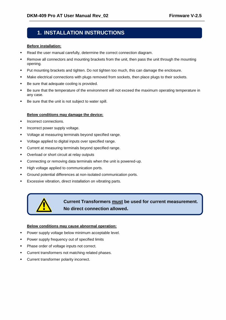
Below conditions may damage the device:
Incorrect connections.
Incorrect power supply voltage.
Voltage at measuring terminals beyond specified range.
Voltage applied to digital inputs over specified range.
Current at measuring terminals beyond specified range.
Overload or short circuit at relay outputs
Connecting or removing data terminals when the unit is powered-up.
High voltage applied to communication ports.
Ground potential differences at non-isolated communication ports.
Excessive vibration, direct installation on vibrating parts.
Below conditions may cause abnormal operation:
Power supply voltage below minimum acceptable level.
Power supply frequency out of specified limits
Phase order of voltage inputs not correct.
Current transformers not matching related phases.
Current transformer polarity incorrect.
1. INSTALLATION INSTRUCTIONS
Current Transformers must be used for current measurement.
No direct connection allowed.
DKM-409 Pro AT User Manual Rev_02 Firmware V-2.5
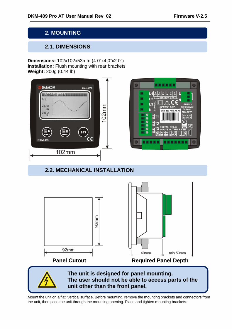
Dimensions: 102x102x53mm (4.0”x4.0”x2.0”) Installation: Flush mounting with rear brackets Weight: 200g (0.44 lb)
Panel Cutout Required Panel Depth
Mount the unit on a flat, vertical surface. Before mounting, remove the mounting brackets and connectors from
the unit, then pass the unit through the mounting opening. Place and tighten mounting brackets.
2. MOUNTING
2.1. DIMENSIONS
2.2. MECHANICAL INSTALLATION
The unit is designed for panel mounting. The user should not be able to access parts of the unit other than the front panel.

DKM-409 Pro AT User Manual Rev_02 Firmware V-2.5
Two different types of brackets are provided:
Screw type bracket
Self retaining type bracket
Installation of screw type bracket
Installation of self retaining type bracket
Do not tighten too much, this may break the unit.
DKM-409 Pro AT User Manual Rev_02 Firmware V-2.5
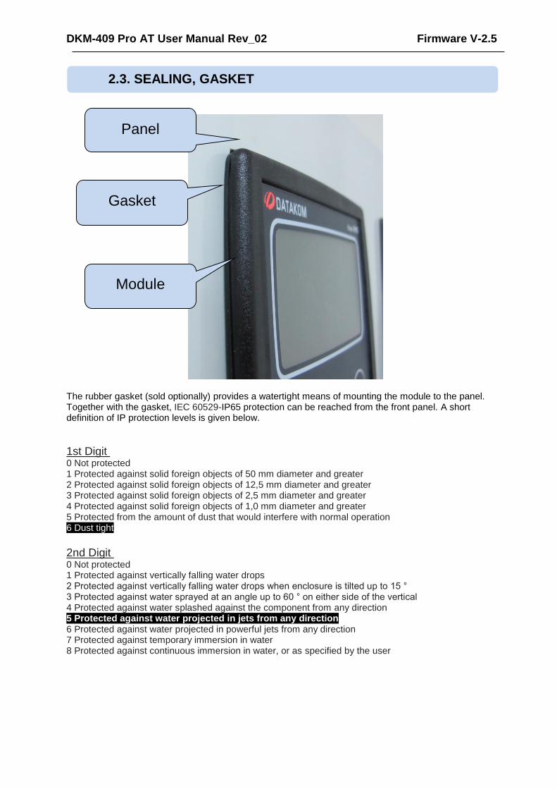
The rubber gasket (sold optionally) provides a watertight means of mounting the module to the panel. Together with the gasket, IEC 60529-IP65 protection can be reached from the front panel. A short definition of IP protection levels is given below.
1st Digit Description of Protection Level 0 Not protected 1 Protected against solid foreign objects of 50 mm diameter and greater 2 Protected against solid foreign objects of 12,5 mm diameter and greater 3 Protected against solid foreign objects of 2,5 mm diameter and greater 4 Protected against solid foreign objects of 1,0 mm diameter and greater 5 Protected from the amount of dust that would interfere with normal operation 6 Dust tight
2nd Digit Description of Protection Level 0 Not protected 1 Protected against vertically falling water drops 2 Protected against vertically falling water drops when enclosure is tilted up to 15 ° 3 Protected against water sprayed at an angle up to 60 ° on either side of the vertical 4 Protected against water splashed against the component from any direction 5 Protected against water projected in jets from any direction 6 Protected against water projected in powerful jets from any direction 7 Protected against temporary immersion in water 8 Protected against continuous immersion in water, or as specified by the user
2.3. SEALING, GASKET
Module
Gasket
Panel

DKM-409 Pro AT User Manual Rev_02 Firmware V-2.5
Although the unit is protected against electromagnetic disturbance, excessive disturbance can affect the operation, measurement precision and data communication quality.
ALWAYS remove plug connectors when inserting wires with a screwdriver.
Fuses must be connected to the power supply and phase voltage inputs, in close proximity of the unit.
Fuses must be of fast type (C) with a maximum rating of 6A.
Use cables of appropriate temperature range.
Use adequate cable section, at least 0.75mm2 (AWG18).
Follow national rules for electrical installation.
Current transformers must have 5A output.
For current transformer inputs, use at least 1.5mm2 section (AWG15) cable.
The current transformer cable length should not exceed 1.5 meters. If longer cable is used, increase the cable section proportionally.
2.4. ELECTRICAL INSTALLATION
Do not install the unit close to high electromagnetic noise emitting devices like contactors, high current busbars, switchmode power supplies and the like.
Current Transformers must be used for current measurement.
No direct connection allowed.
For the correct recording of events, adjust the real time clock of the unit through programming menu.
DKM-409 Pro AT User Manual Rev_02 Firmware V-2.5
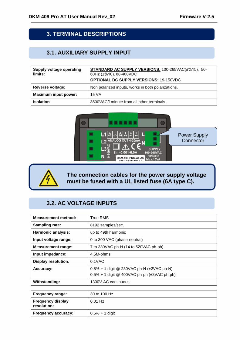
Supply voltage operating limits:
STANDARD AC SUPPLY VERSIONS: 100-265VAC(±%15), 50-60Hz (±%10), 88-400VDC
OPTIONAL DC SUPPLY VERSIONS: 19-150VDC
Reverse voltage: Non polarized inputs, works in both polarizations.
Maximum input power: 15 VA
Isolation 3500VAC/1minute from all other terminals.
Measurement method: True RMS
Sampling rate: 8192 samples/sec.
Harmonic analysis: up to 49th harmonic
Input voltage range: 0 to 300 VAC (phase-neutral)
Measurement range: 7 to 330VAC ph-N (14 to 520VAC ph-ph)
Input impedance: 4.5M-ohms
Display resolution: 0.1VAC
Accuracy: 0.5% + 1 digit @ 230VAC ph-N (±2VAC ph-N)
0.5% + 1 digit @ 400VAC ph-ph (±3VAC ph-ph)
Withstanding: 1300V-AC continuous
Frequency range: 30 to 100 Hz
Frequency display resolution:
0.01 Hz
Frequency accuracy: 0.5% + 1 digit
3. TERMINAL DESCRIPTIONS
3.1. AUXILIARY SUPPLY INPUT
The connection cables for the power supply voltage must be fused with a UL listed fuse (6A type C).
3.2. AC VOLTAGE INPUTS
Power Supply Connector

DKM-409 Pro AT User Manual Rev_02 Firmware V-2.5
Structure: Isolated, internal current transformers
Measurement method: True RMS
Sampling rate: 8192 samples/sec.
Harmonic analysis: up to 49th harmonic
CT secondary rating: 5A
Measurement range: 5/5 - 50000/5A minimum
Input impedance: 15 mili-ohm
Burden: 0.375W
Maximum current: 6A continuous
Measurement range: 0.001 to 6A AC
Display resolution: 0.1A
Accuracy: 0.5% + 1 digit
Isolation: 1000VAC/1minute from all other terminals.
Withstand: 100A-AC for 1 second
SELECTING THE CT RATING AND CABLE SECTION:
The load on a CT should be kept minimum in order to minimize phase shift effect of the current transformer. Phase shift in a CT will cause erroneous power and power factor readings, although amp readings are correct.
Datakom advises CT rating to be selected following this table for the best measurement accuracy.
SELECTING THE CT ACCURACY CLASS:
The CT accuracy class should be selected in accordance with the required measurement precision. The accuracy class of the Datakom controller is 0.5%. Thus 0.5% class CTs are advised for the best result.
CONNECTING CTs:
Be sure of connecting each CT to the related phase input with the correct polarity. Mixing CTs between phases will cause faulty power and pf readings.
Many combinations of incorrect CTs connections are possible, so check both order of CTs and their polarity. Reactive power measurement is affected by incorrect CTs connection in similar way as active power measurement.
3.3. AC CURRENT INPUTS

DKM-409 Pro AT User Manual Rev_02 Firmware V-2.5
CORRECT CT CONNECTIONS
Let’s suppose that the network is loaded with 100 kW on each phase. The load Power Factor (PF) is 1. Measured values are as follows:
kW kVAr kVA pf
Phase L1 100.0 0.0 100 1.00
Phase L2 100.0 0.0 100 1.00
Phase L3 100.0 0.0 100 1.00
Total 300.0 0.0 300 1.00
EFFECT OF POLARITY REVERSAL
The network is still loaded with 100 kW On each phase. The load Power Factor (PF) is 1. PF in phase L2 will show -1,00 due to reverse CT polarity. The result is that total network power displayed by the controller is 100 kW. Measured values are as follows:
kW kVAr kVA pf
Phase L1 100.0 0.0 100 1.00
Phase L2 -100.0 0.0 100 -1.00
Phase L3 100.0 0.0 100 1.00
Total 100.0 0.0 300 0.33

DKM-409 Pro AT User Manual Rev_02 Firmware V-2.5
EFFECT OF PHASE SWAPPING
The network is still loaded with 100 kW on each phase. The load Power Factor (PF) is 1. PF in phases L2 and L3 will show -0,50 due to phase shift between voltages and currents which is caused by CT swapping. The result is that total network power displayed by controller is 0 kW. Measured values are as follows:
kW kVAr kVA pf
Phase L1 100.0 0.0 100 1.00
Phase L2 -50.0 86.6 100 -0.50
Phase L3 -50.0 -86.6 100 -0.50
Total 0.0 0.0 300 0.0
Number of inputs: 4 inputs, all configurable
Input type: Opto-isolated digital input
Function selection: From list
Contact type: Normally open or normally closed (programmable)
Minimum pulse duration: 250ms
Active level: 40-135V-DC or 30-265V-AC
Isolation: 1000VAC, 1 minute
Noise filtering: Yes
3.4. DIGITAL INPUTS

DKM-409 Pro AT User Manual Rev_02 Firmware V-2.5
Structure: Relay output, normally open, free contact output
Max switching current: 5A @250VAC
Max switching voltage: 250VAC
Max switching power: 1250VA
Structure: RS-485, isolated.
Connection: 3 wires (A-B-GND). Half duplex.
Baud rate: 2400-115200 bauds, selectable
Data type: 8 bit data, no parity, 1 bit stop
Termination: External 120 ohms required
Common mode voltage: -0.5 VDC to +7VDC, internally clamped by transient suppressors.
Max distance: 1200m @ 9600 bauds (with 120 ohms balanced cable)
200m @ 115200 bauds (with 120 ohms balanced cable)
Isolation: 500VAC, 1 minute
The RS-485 port features MODBUS-RTU protocol. Multiple modules (up to 128) can be paralleled on the same RS-485 bus for data transfer to automation or building management systems.
The RS-485 port provides also a good solution for distant PC connection where RainbowPlus program will enable programming, control and monitoring.
RS-485 BUS STRUCTURE
A maximum of 32 devices can be paralleled on a RS-485 bus. For more devices on one bus, repeaters must be used.
The bus must be terminated from both ends with 120 ohm resistor.
The cable shield should be grounded from one end only.
A B A B A BA B
120R 120R
3.5. RELAY OUTPUTS
3.6. RS-485 PORT
The Modbus register list is available at the MODBUS section of this manual.
The device does not have any internal terminating resistors. External 120 ohm resistor should be added to both extremities of the bus line.
DKM-409 Pro AT User Manual Rev_02 Firmware V-2.5
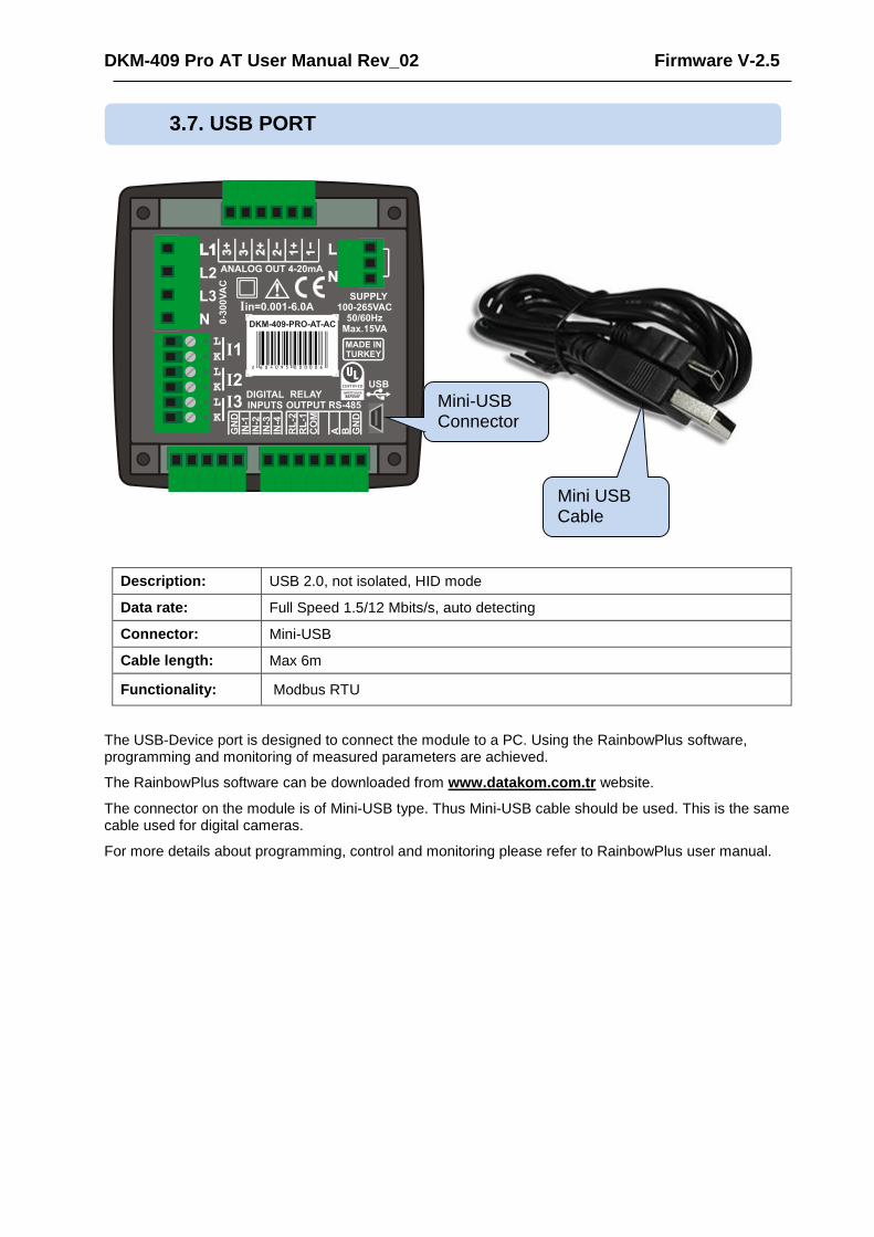
Description: USB 2.0, not isolated, HID mode
Data rate: Full Speed 1.5/12 Mbits/s, auto detecting
Connector: Mini-USB
Cable length: Max 6m
Functionality: Modbus RTU
The USB-Device port is designed to connect the module to a PC. Using the RainbowPlus software, programming and monitoring of measured parameters are achieved.
The RainbowPlus software can be downloaded from www.datakom.com.tr website.
The connector on the module is of Mini-USB type. Thus Mini-USB cable should be used. This is the same cable used for digital cameras.
For more details about programming, control and monitoring please refer to RainbowPlus user manual.
3.7. USB PORT
Mini-USB Connector
Mini USB Cable
DKM-409 Pro AT User Manual Rev_02 Firmware V-2.5
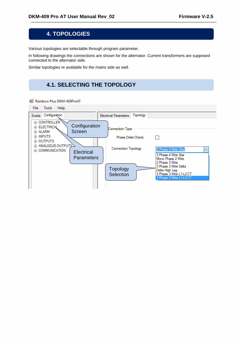
Various topologies are selectable through program parameter.
In following drawings the connections are shown for the alternator. Current transformers are supposed connected to the alternator side.
Similar topologies re available for the mains side as well.
4. TOPOLOGIES
4.1. SELECTING THE TOPOLOGY
Configuration Screen
Topology Selection
Electrical Parameterss

DKM-409 Pro AT User Manual Rev_02 Firmware V-2.5
4.2. 3 PHASE, 4 WIRE, STAR
4.3. 3 PHASE, 3 WIRE, DELTA

DKM-409 Pro AT User Manual Rev_02 Firmware V-2.5
4.4. 3 PHASE, 4 WIRE, DELTA
4.5. 3 PHASE, 3 WIRE, DELTA, 2 CT (L1-L2)

DKM-409 Pro AT User Manual Rev_02 Firmware V-2.5
4.6. 3 PHASE, 3 WIRE, DELTA, 2 CT (L1-L3)
4.7. 2 PHASE, 3 WIRE, DELTA, 2 CTs (L1-L2)

DKM-409 Pro AT User Manual Rev_02 Firmware V-2.5
4.8. 1 PHASE, 2 WIRE

DKM-409 Pro AT User Manual Rev_02 Firmware V-2.5
5. CONNECTION DIAGRAM

DKM-409 Pro AT User Manual Rev_02 Firmware V-2.5
Supply Input: 100-265V AC (±15%), 50/60Hz (±10%),
88-400V DC Measurement Inputs:
Voltage: 7 - 300 V AC (P-N)
14 - 520 V AC (P-P) Current: 0.001 – 6.00 A AC Frequency: 30 - 100 Hz
Accuracy: Voltage: 0.5% + 1 digit
Current: 0.5% + 1 digit Frequency: 0.5% + 1 digit Power (kW,kVAr):1.0% + 2 digit Cos: 0.5% + 1 digit Withstanding: Current: 100 A AC during 1 sec. Voltage: 1300 V AC (continuous) Analog Outputs: Active 4-20mA Precision: 16 bit Measurement Range: CT range: 5/5A to 50000/5A
VT range: 0.1/1 to 5000.0/1 kW range: 1.0 kW to 5000 MW
Power Consumption: < 15 VA Voltage Burden: < 0.02VA per phase Current Burden: < 0.5VA per phase Relay Outputs: 5A @ 250V AC Digital Inputs: Active level: 40 to 135V DC or 30 to 265V AC Min pulse: 250ms. Isolation: 1000V AC, 1 minute Serial Port: Signal level: RS-485 Protocol: Modbus RTU Data Rate: Adjustable 2400-115200 bauds İsolation: 500V AC, 1 minute Operating Temp. Range: -20°C to +70 °C (-4°F to 158°F) Max Humidity: 95%, non-condensing Degree of Protection: IP 54 (Front Panel)
IP 30 (Back Panel) Enclosue: Non-flammable, ROHS compliant Installation: Flush mounting with rear brackets Dimensions: 102x102x53mm (WxHxD) Panel Cutout: 92x92mm Weight: 200 gr
EU Directives:
2006/95/EC (LVD) 2004/108/EC (EMC)
Norms of Reference:
EN 61010 (safety) EN 61326 (EMC)
UL-CSA Certification:
UL 61010-1, 3rd Edition, 2012-05, CAN/CSA-C22.2 File: E475547, Vol. D1
6. TECHNICAL SPECIFICATIONS
DKM-409 Pro AT User Manual Rev_02 Firmware V-2.5
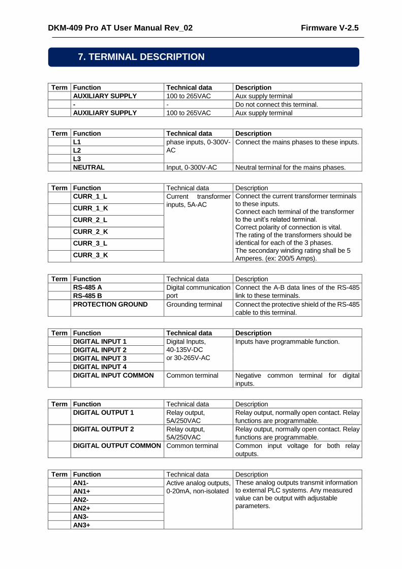
Term Function Technical data Description
AUXILIARY SUPPLY 100 to 265VAC Aux supply terminal
- - Do not connect this terminal.
AUXILIARY SUPPLY 100 to 265VAC Aux supply terminal
Term Function Technical data Description
L1 phase inputs, 0-300V-
AC
Connect the mains phases to these inputs.
L2
L3
NEUTRAL Input, 0-300V-AC Neutral terminal for the mains phases.
Term Function Technical data Description
CURR_1_L Current transformer
inputs, 5A-AC
Connect the current transformer terminals to these inputs. Connect each terminal of the transformer to the unit’s related terminal. Correct polarity of connection is vital. The rating of the transformers should be identical for each of the 3 phases. The secondary winding rating shall be 5 Amperes. (ex: 200/5 Amps).
CURR_1_K
CURR_2_L
CURR_2_K
CURR_3_L
CURR_3_K
Term Function Technical data Description
RS-485 A Digital communication
port
Connect the A-B data lines of the RS-485
link to these terminals. RS-485 B
PROTECTION GROUND Grounding terminal Connect the protective shield of the RS-485
cable to this terminal.
Term Function Technical data Description
DIGITAL INPUT 1 Digital Inputs,
40-135V-DC
or 30-265V-AC
Inputs have programmable function.
DIGITAL INPUT 2
DIGITAL INPUT 3
DIGITAL INPUT 4
DIGITAL INPUT COMMON Common terminal Negative common terminal for digital
inputs.
Term Function Technical data Description
DIGITAL OUTPUT 1 Relay output,
5A/250VAC
Relay output, normally open contact. Relay
functions are programmable.
DIGITAL OUTPUT 2 Relay output,
5A/250VAC
Relay output, normally open contact. Relay
functions are programmable.
DIGITAL OUTPUT COMMON Common terminal Common input voltage for both relay
outputs.
Term Function Technical data Description
AN1- Active analog outputs,
0-20mA, non-isolated
These analog outputs transmit information to external PLC systems. Any measured value can be output with adjustable parameters.
AN1+
AN2-
AN2+
AN3-
AN3+
7. TERMINAL DESCRIPTION

DKM-409 Pro AT User Manual Rev_02 Firmware V-2.5
BUTTON FUNCTION
Selects next display group.
Held pressed for 3 seconds:
Remove alarms.
Selects previous display screen in the same display group.
Held pressed for 10 seconds:
Current screen will be default display screen
Selects next display screen in the same display group.
Held pressed for 3 seconds:
Enable programming mode.
8. DESCRIPTION OF CONTROLS
8.1. FRONT PANEL FUNCTIONALITY
8.2. PUSHBUTTON FUNCTIONS
LCD screen
Next screen in the same group.
Next display group
Previous screen in the same group.
DKM-409 Pro AT User Manual Rev_02 Firmware V-2.5
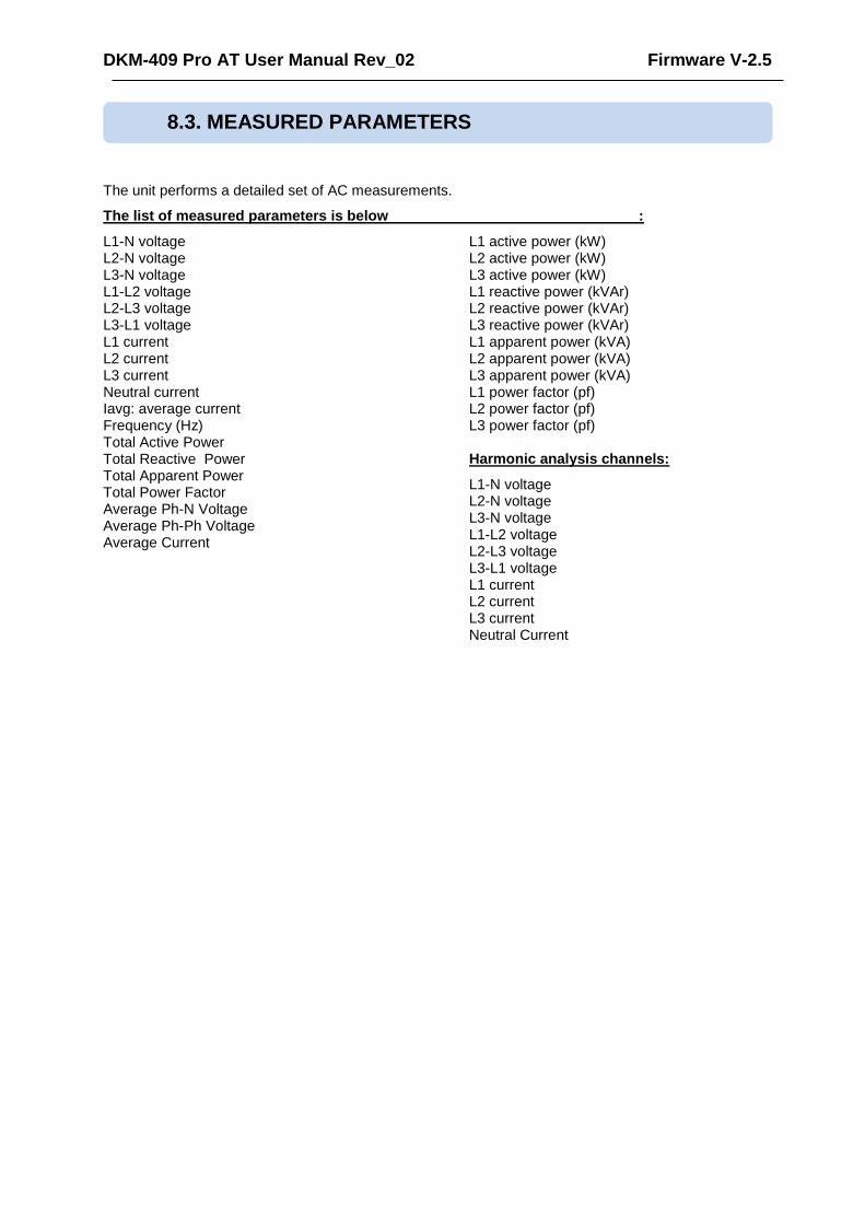
The unit performs a detailed set of AC measurements.
The list of measured parameters is below :
L1-N voltage L2-N voltage L3-N voltage L1-L2 voltage L2-L3 voltage L3-L1 voltage L1 current L2 current L3 current Neutral current Iavg: average current Frequency (Hz) Total Active Power Total Reactive Power Total Apparent Power Total Power Factor Average Ph-N Voltage Average Ph-Ph Voltage Average Current
L1 active power (kW) L2 active power (kW) L3 active power (kW) L1 reactive power (kVAr) L2 reactive power (kVAr) L3 reactive power (kVAr) L1 apparent power (kVA) L2 apparent power (kVA) L3 apparent power (kVA) L1 power factor (pf) L2 power factor (pf) L3 power factor (pf) Harmonic analysis channels:
L1-N voltage L2-N voltage L3-N voltage L1-L2 voltage L2-L3 voltage L3-L1 voltage L1 current L2 current L3 current Neutral Current
8.3. MEASURED PARAMETERS

DKM-409 Pro AT User Manual Rev_02 Firmware V-2.5
SYMBOL DEFINITION
Ver Firmware
U12 Phase 1 - Phase 2 AC RMS Voltage
U23 Phase 2 - Phase 3 AC RMS Voltage
U31 Phase 3 - Phase 1 AC RMS Voltage
FRQ Frequency
V1 Phase 1 - Neutral AC RMS Voltage
V2 Phase 2 - Neutral AC RMS Voltage
V3 Phase 3 - Neutral AC RMS Voltage
I1 Phase 1 AC RMS Current
I2 Phase 2 AC RMS Current
I3 Phase 3 AC RMS Current
P1 Phase 1 Active Power (kW)
P2 Phase 2 Active Power (kW)
P3 Phase 3 Active Power (kW)
∑P Total Active Power (kW)
Q1 Phase 1 Reactive Power (kVar)
Q2 Phase 2 Reactive Power (kVar)
Q3 Phase 3 Reactive Power (kVar)
∑Q Total Reactive Power (kVar)
S1 Phase 1 Apparent Power (kVA)
S2 Phase 2 Apparent Power (kVA)
S3 Phase 3 Apparent Power (kVA)
∑S Total Apparent Power (kVA)
PF1 Phase 1 Power Factor
PF2 Phase 2 Power Factor
PF3 Phase 3 Power Factor
PF Total Power Factor
I1mx Phase 1 Maximum Current
I2mx Phase 2 Maximum Current
I3mx Phase 3 Maximum Current
Pmax Total Maximum Active Power
PIm1 Import Power Counter 1 (kWh)
PEx1 Export Power Counter 1 (kWh)
PIm2 Import Power Counter 2 (kWh)
PEx2 Export Power Counter 2 (kWh)
QIn1 Inductive Power Counter 1 (kVar)
QCp1 Capacitive Power Counter 1 (kVar)
QIn2 Inductive Power Counter 2 (kVar)
QCp2 Capacitive Power Counter 2 (kVar)
AO-1 Analogue Output 1
AO-2 Analogue Output 2
AO-3 Analogue Output 3
THD Total Harmonic Distortion
Th… Total Harmonic of … (V1,V2,V3,I1,I2,I3,U1,U2,U3)
H03-H49 Harmonics
9. INDICATOR SYMBOLS

DKM-409 Pro AT User Manual Rev_02 Firmware V-2.5
The unit performs a detailed set of AC measurements. Displaying these parameters are organized under PARAMETER GROUPS and subgroups.
Switching between parameter groups are made with button.
Each depression of the button switches the screen to the next parameter group. After the last group, the first group is displayed again.
Switching within the same group is performed with and buttons.
Each depression of the button switches the screen to the next display in the same group. After the last display, the first display comes again.
Each depression of the button switches the screen to the previous display in the same group. After the first display, the last display comes again.
The list of parameter groups are below:
Measurement Screens: Voltage, current, kW, kVA, kVAr, pf, active and reactive energy counters.
Demand Screen: Demand current, demand power; minimum, maximum of current, voltages, reactive and capacitive powers.
Status Group: Various information as date-time, firmware version, identity, configuration, etc...
User Screens: Screens in this group are configured by the user.
Oscilloscope Screens: In this group, waveforms of currents and voltages may be visualized as an oscilloscope. All phase-neutral and phase-phase voltages and each current input are available. Thanks to this feature, waveform distortions and harmonic components are displayed in graphical form.
Harmonic Analysis Result Tables: In this group, THDs of currents and voltages are displayed with 0.1% precision. All phase-neutral and phase-phase voltages and each current input are available.
9.1. SCREEN SCROLLING

DKM-409 Pro AT User Manual Rev_02 Firmware V-2.5
The unit features waveform display together with a precision harmonic analyzer for both voltages and currents. Both phase to neutral and phase to phase voltages are available for analysis.
Scopemeter Display
The waveform display memory is of 100 samples length and 12 bit resolution, with a sampling rate of 2048 s/s. Thus one cycle of a a 50Hz signal is represented with 41 points. The vertical scale is automatically adjusted in order to avoid clipping of the signal.
The waveform is displayed on the device screen, and with more resolution on PC screen through the RainbowPlus program.
The display memory is also available in the Modbus register area for third party applications. For more details please check chapter “MODBUS Communications”.
The harmonic analyzer consists on a Fast Fourier Transform (FFT) algorithm which is run twice a second on the selected parameter.
The sample memory is 1024 samples length and 12 bits resolution with a sampling rate of 8196 s/s.
The unit is able to analyze up to 2500Hz and up to 49th harmonic, whichever is smaller.
Harmonics Display Screens
All harmonics are displayed with 0.1% resolution.
On RainbowPlus program, harmonics and waveform are displayed with more resolution.
RainbowPlus Scada section: Waveform Display and Harmonics
10. WAVEFORM DISPLAY & HARMONIC ANALYSIS

DKM-409 Pro AT User Manual Rev_02 Firmware V-2.5
Thanks to its internal astronomical relay function, the unit calculates sunrise and sunset times with precision, using geographical coordinates and date.
Using the astronomical relay function it is possible turn on/off lights and activate various equipment depending on sunrise and sunset.
Astronomical relay display screen
Astronomical relay parameter setting is performed through LOCATION SETUP group of the programming menu.
The date-time information is picked-up from the internal real time clock circuit.
Geographical position information is programmed by direct entry of latitude and longitude.
The unit is capable of activating a relay following sunrise and sunset times. The delay before sunrise and the delay after sunset are programmable.
11. ASTRONOMIC RELAY FUNCTIONALITY

DKM-409 Pro AT User Manual Rev_02 Firmware V-2.5
The device offers a powerful user screen design tool through programming menu. The user can freely design his own screen for the most specialized functionality. Any measured value may be set on the display, using 2 different possible font sizes. The display can hold 4 lines in large characters or 8 lines in small characters. When small characters are used, 2 columns are permitted. The capacity of the screen therefore becomes 4 large size values or 16 small size values or any combination of them. Above is a sample user defined screen. The device offers 4 independent user defined screens, totalizing the amount of possible parameters to 64 items. User screen names are also editable for additional flexibility.
12. USER CONFIGURABLE DISPLAY SCREENS
For more details about user screen configuration please review chapter CONFIGURING USER DISPLAY SCREENS at the PROGRAMMING section of this manual.
DKM-409 Pro AT User Manual Rev_02 Firmware V-2.5
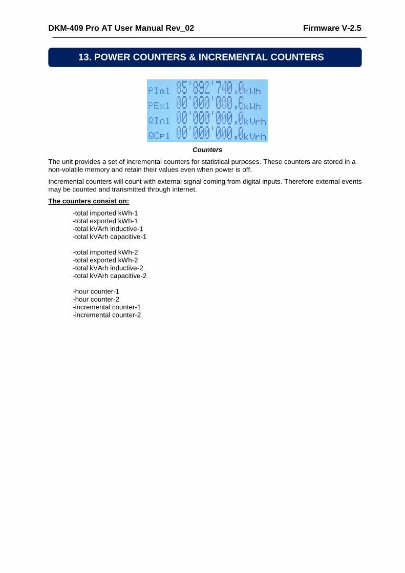
Counters
The unit provides a set of incremental counters for statistical purposes. These counters are stored in a non-volatile memory and retain their values even when power is off.
Incremental counters will count with external signal coming from digital inputs. Therefore external events may be counted and transmitted through internet.
The counters consist on:
-total imported kWh-1 -total exported kWh-1 -total kVArh inductive-1 -total kVArh capacitive-1 -total imported kWh-2 -total exported kWh-2 -total kVArh inductive-2 -total kVArh capacitive-2
-hour counter-1 -hour counter-2
-incremental counter-1 -incremental counter-2
13. POWER COUNTERS & INCREMENTAL COUNTERS
DKM-409 Pro AT User Manual Rev_02 Firmware V-2.5
Demand values are average values of measured parameters over a programmable period.
The average values at the end of the period are compared with the demand registers, if higher, the new demand is stored into the register.
Demand registers are reset at the beginning of each month. Therefore demands are effective for the current month.
Demands may also be manually reset through programming menu MIN/MAX COUNTER ADJUST section.
Demand registers are stored in a non-volatile memory and retain their values even when power is off.
Below demand registers are available:
-demand I1 -demand I2 -demand I3 -demand Ia (average current) -demand import active power -demand export active power
Min-max values are based on instantaneous measurements. They have no averaging periods, therefore excessive values may be stored during short duration peak demands, like electric motor starts or inrush currents that flow at power-on.
During operation, the unit compares the instantaneous value with the storage registers, if higher, the new value is stored into the register.
Min-max registers are reset through programming mode. The related parameter is: COUNTER/MIN/MAX>Restart Min/Max
Min-max registers are stored in a non-volatile memory and retain their values even when power is off.
For stability purposes, the min-max detection starts 5 seconds after power turns on.
Below min-max registers are available :
-Min voltage L1-N -Min voltage L2-N -Min voltage L3-N -Min voltage L1-2 -Min voltage L2-3 -Min voltage L3-1 -Min frequency -Min current I1 -Min current I2 -Min current I3 -Min current Ia (average current) -Min import active power -Min export active power -Min inductive reactive power -Min capacitive reactive power
-Max voltage L1-N -Max voltage L2-N -Max voltage L3-N -Max voltage L1-2 -Max voltage L2-3 -Max voltage L3-1 -Max frequency -Max current I1 -Max current I2 -Max current I3 -Max current Ia (average current) -Max import active power -Max export active power -Max inductive reactive power -Max capacitive reactive power
14. DEMAND VALUES
15. MIN-MAX VALUES
DKM-409 Pro AT User Manual Rev_02 Firmware V-2.5
K91D01-EN - 36 -
The unit features more than 400 event logs with date-time stamp and full snapshot of measured values at the moment that the event has occurred.
Stored values in an event record are listed below:
-event number -event type / fault definition (see below for various event sources) -date and time -binary values of all alarm, input and output bits. -Ph-N voltages: V1-V2-V3 -Ph-Ph voltages: U12-U23-U31 -Phase currents: I1-I2-I3 -frequency -total active power (kW) -total reactive power (kVAr) -total apparent power (kVA) -total power factor -Total harmonic distortion: V1-V2-V3-U12-U23-U31-I1-I2-I3
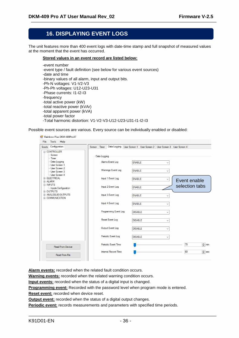
Possible event sources are various. Every source can be individually enabled or disabled:
Alarm events: recorded when the related fault condition occurs.
Warning events: recorded when the related warning condition occurs.
Input events: recorded when the status of a digital input is changed.
Programming event: Recorded with the password level when program mode is entered.
Reset event: recorded when device reset.
Output event: recorded when the status of a digital output changes.
Periodic event: records measurements and parameters with specified time periods.
16. DISPLAYING EVENT LOGS
Event enable selection tabs

DKM-409 Pro AT User Manual Rev_02 Firmware V-2.5
K91D01-EN - 37 -
Event logs are displayed within the program mode menu. This is designed in order to reduce the interference of event logs with other measurement screens.
To monitor event logs, press together with and buttons for 5 seconds.
When the program mode is entered, below password entry screen will be displayed.
Type password as “9876” by using and buttons to increase or decrease the number in
highlighted digit, button to type next digit. Click button to reach programming mode.
Click button again to see last stored event. The first page will display the event number, event type,
fault type and date-time information.
When displaying event logs:
button will display the next information in the same event, when held pressed returns to the main programming screen.
button will display the same information of the previous event
button will display the same information of the next event.
Press 2 buttons for 5 seconds
Type password
DKM-409 Pro AT User Manual Rev_02 Firmware V-2.5
K91D01-EN - 38 -
Measured analog values outside of programed limits cause an ALARM condition.
When an alarm condition occurs, the alarm pop-up display appears and the alarm function will become active. The alarm function may be assigned to a relay output, enabling transfer to other systems.
Each alarm has programmable low/high limits and timer. If the alarm condition disappears before the timer
expires, it will not trigger the alarm display.
Alarms may be of LATCHING type following programming. For latching alarms, even if the alarm condition is
removed, the alarms will stay on.
Most alarms have programmable trip levels. See the programming chapter for adjustable alarm limits.
17. PROTECTIONS AND ALARMS
If a fault condition occurs, the display will automatically show the alarm pop-up window.
DKM-409 Pro AT User Manual Rev_02 Firmware V-2.5
K91D01-EN - 39 -
The program mode is used to adjust timers, operational limits and the configuration of the unit. Although a free PC
program is provided for programming, every parameter may be modified through the front panel.
Program parameters will be automatically recorded into a non-erasable memory and take effect immediately after
modification. Moreover, the program mode will not affect the operation of the unit. Therefore, programs may be
modified anytime.
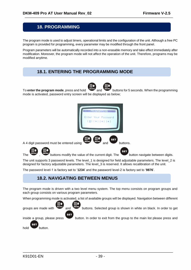
To enter the program mode, press and hold and buttons for 5 seconds. When the programming
mode is activated, password entry screen will be displayed as below;
A 4 digit password must be entered using and buttons.
The , buttons modify the value of the current digit. The button navigate between digits.
The unit supports 3 password levels. The level_1 is designed for field adjustable parameters. The level_2 is designed for factory adjustable parameters. The level_3 is reserved. It allows recalibration of the unit.
The password level-1 is factory set to ‘1234’ and the password level-2 is factory set to ‘9876’.
The program mode is driven with a two level menu system. The top menu consists on program groups and
each group consists on various program parameters.
When programming mode is activated, a list of available groups will be displayed. Navigation between different
groups are made with and buttons. Selected group is shown in white on black. In order to get
inside a group, please press button. In order to exit from the group to the main list please press and
hold button.
18. PROGRAMMING
18.1. ENTERING THE PROGRAMMING MODE
18.2. NAVIGATING BETWEEN MENUS

DKM-409 Pro AT User Manual Rev_02 Firmware V-2.5
K91D01-EN - 40 -
Navigation inside a group is also made with and buttons. A list of available parameters will be
displayed. Selected parameter is shown in white on black. In order display/change the value of this parameter,
please press button. Parameter value may be increased and decreased with and buttons.
When a program parameter is modified, it is automatically saved in memory. If button is pressed, next
parameter will be displayed.
To exit the program mode press one of the mode selection keys. If no button is pressed during 2 minutes the program mode will be cancelled automatically.
18.3. MODIFYING PARAMETER VALUE
18.4. PROGRAMMING MODE EXIT
Next group
Previous group
Enter inside the group
Decrease parameter value
Increase parameter value
Next parameter
Press and hold these two buttons for 5 seconds

DKM-409 Pro AT User Manual Rev_02 Firmware V-2.5
K91D01-EN - 41 -
Parameter Definition Unit Min Max Factory Set
Description
Language Selection - 0 1 0
0: English language selected. 1: Local language selected. This language may depend on the country where the unit is intended to be used.
Intermittent Alarm Timer sec 0 255 1 If Intermittent Relay parameter is 1, then the HORN relay is activated and deactivated with this period.
Horn Timer sec 0 120 60
This is the period during which the HORN relay is active. If the period is set to 0, this will mean that the period is unlimited.
Periodic Event Time Min 0 65000 60 Specifies period for periodic data log.
RS-485 Enable - 0 1 1 0: RS-485 port disabled 1: RS-485 port enabled
Modbus Address - 0 254 1 This is the modbus controller identity used in Modbus communication.
RS-485 Baud Rate bps 2400 115200 9600 This is the data rate of the RS-485 Modbus port.
Intermittent Alarm Relay - 0 1 0 0: Continuous 1: Intermittent
Alarms Event Log - 0 1 1 0: Disabled 1: Enabled
Warning event Log - 0 1 1 0: Disabled 1: Enabled
Input 1 Event Log - 0 1 1 0: Disabled 1: Enabled
Input 2 Event Log - 0 1 1 0: Disabled 1: Enabled
Input 3 Event Log - 0 1 1 0: Disabled 1: Enabled
Input 4 Event Log - 0 1 1 0: Disabled 1: Enabled
Programming Event Log - 0 1 1 0: Disabled 1: Enabled
Reset Event Log - 0 1 0 0: Disabled 1: Enabled
Output Event Log - 0 1 1 0: Disabled 1: Enabled
Periodic Event Log - 0 1 0 0: Disabled 1: Enabled
LCD Backlight Timer min 0 1440 0
If no button is pressed during this period, then the unit will reduce the LCD screen backlight intensity in for economy.
Flashing Relay ON Timer min 0 6000 0 Flashing relay ON state duration timer.
Flashing Relay OFF Timer
min 0 6000 0 Flashing relay OFF state duration.
Internal Record Timer sec 2 65000 60
Defines the data recording period to internal memory. Shorter periods will cause the internal memory to roll-up more often.
Modbus Packet Type 0 1 0 Do not change this parameter. It affects the Modbus register map.
19. PROGRAM PARAMETER LIST
19.1. CONTROLLER CONFIGURATION GROUP

DKM-409 Pro AT User Manual Rev_02 Firmware V-2.5
K91D01-EN - 42 -
Parameter Definition Unit Min Max Factory Set
Description
Current Transformer Configuration
- 5/5 25000/1 600/1 This is the primary and secondary windings of current transformer.
Voltage Transformer Ratio
- 0 5000 1.0
This is the voltage transformer ratio. This value will multiply all voltage and power readings. If transformers are not used, the ratio should be set to 1.0
Alarm Mute Timer sec 0 255 20 If the alarm is selected non-latching, then the alarm condition disappears this timer after the alarm signal goes off.
Mains Phase Order Check Enable
- 0 1 0 0: mains phase order checking disabled 1: if mains phase order is faulty, then an alarm occurs.
Volt Low Alarm V 0 65000 0
If the voltage of any phase falls below this limit, this will cause an alarm. If this limit is 0 then low voltage alarm is not controlled.
Volt High Alarm V 0 65000 0
If the voltage of any phase goes above this limit, this will cause an alarm. If this limit is 0 then high voltage alarm is not controlled.
Volt Alarm Duration sec 0 255 30 If the voltage goes outside of the limits during this timer, a voltage alarm will occur.
Volt Alarm Lock Enable - 0 1 1 0: alarm non latching 1: latching alarm
Frequency Low Alarm Hz 0 400 0
If the frequency goes under this limit, this will cause an alarm. If this limit is 0 then the alarm is not controlled.
Frequency High Alarm Hz 0 400 0
If the frequency goes above this limit, this will cause an alarm. If this limit is 0 then the alarm is not controlled.
Frequency Alarm Duration
sec 0 255 30 If the frequency goes outside of the limits during this timer, a frequency alarm will occur.
Frequency Alarm Lock Enable
- 0 1 1 0: alarm non latching 1: latching alarm
Active Power Low Alarm kW 0 9999 0
If the active power of any channel goes under this limit, this will cause an alarm. If this limit is 0 then the alarm is not controlled.
Active Power High Alarm kW 0 9999 0
If the active power of any channel goes above this limit, this will cause an alarm. If this limit is 0 then the alarm is not controlled.
Active Power Alarm Duration
sec 0 255 30 If the active power of any channel goes outside of the limits during this timer, an active power alarm will occur.
Active Power Alarm Lock Enable
- 0 1 1 0: alarm non latching 1: latching alarm
19.2. ELECTRICAL PARAMETERS GROUP
DKM-409 Pro AT User Manual Rev_02 Firmware V-2.5
K91D01-EN - 43 -
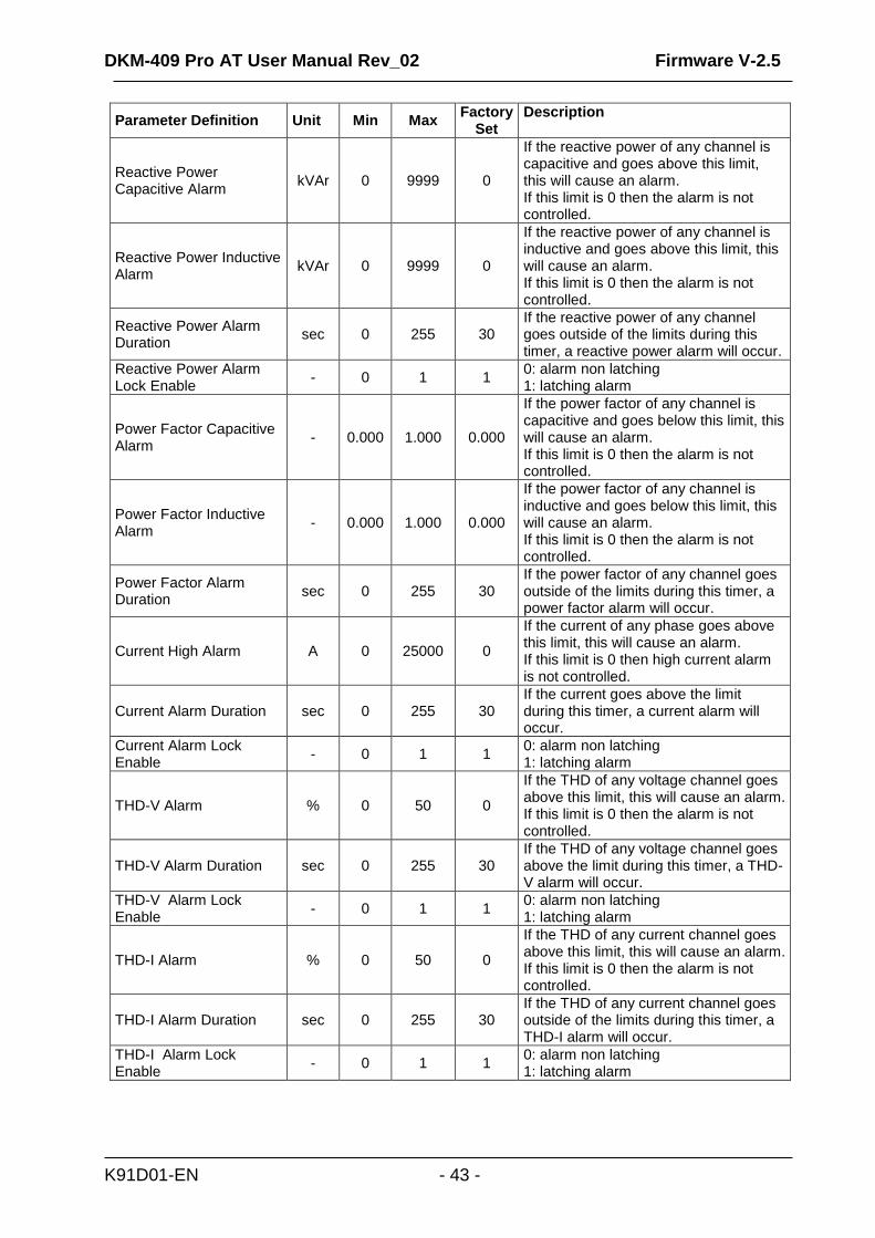
Parameter Definition Unit Min Max Factory
Set Description
Reactive Power Capacitive Alarm
kVAr 0 9999 0
If the reactive power of any channel is capacitive and goes above this limit, this will cause an alarm. If this limit is 0 then the alarm is not controlled.
Reactive Power Inductive Alarm
kVAr 0 9999 0
If the reactive power of any channel is inductive and goes above this limit, this will cause an alarm. If this limit is 0 then the alarm is not controlled.
Reactive Power Alarm Duration
sec 0 255 30 If the reactive power of any channel goes outside of the limits during this timer, a reactive power alarm will occur.
Reactive Power Alarm Lock Enable
- 0 1 1 0: alarm non latching 1: latching alarm
Power Factor Capacitive Alarm
- 0.000 1.000 0.000
If the power factor of any channel is capacitive and goes below this limit, this will cause an alarm. If this limit is 0 then the alarm is not controlled.
Power Factor Inductive Alarm
- 0.000 1.000 0.000
If the power factor of any channel is inductive and goes below this limit, this will cause an alarm. If this limit is 0 then the alarm is not controlled.
Power Factor Alarm Duration
sec 0 255 30 If the power factor of any channel goes outside of the limits during this timer, a power factor alarm will occur.
Current High Alarm A 0 25000 0
If the current of any phase goes above this limit, this will cause an alarm. If this limit is 0 then high current alarm is not controlled.
Current Alarm Duration sec 0 255 30 If the current goes above the limit during this timer, a current alarm will occur.
Current Alarm Lock Enable
- 0 1 1 0: alarm non latching 1: latching alarm
THD-V Alarm % 0 50 0
If the THD of any voltage channel goes above this limit, this will cause an alarm. If this limit is 0 then the alarm is not controlled.
THD-V Alarm Duration sec 0 255 30 If the THD of any voltage channel goes above the limit during this timer, a THD-V alarm will occur.
THD-V Alarm Lock Enable
- 0 1 1 0: alarm non latching 1: latching alarm
THD-I Alarm % 0 50 0
If the THD of any current channel goes above this limit, this will cause an alarm. If this limit is 0 then the alarm is not controlled.
THD-I Alarm Duration sec 0 255 30 If the THD of any current channel goes outside of the limits during this timer, a THD-I alarm will occur.
THD-I Alarm Lock Enable
- 0 1 1 0: alarm non latching 1: latching alarm
DKM-409 Pro AT User Manual Rev_02 Firmware V-2.5
K91D01-EN - 44 -
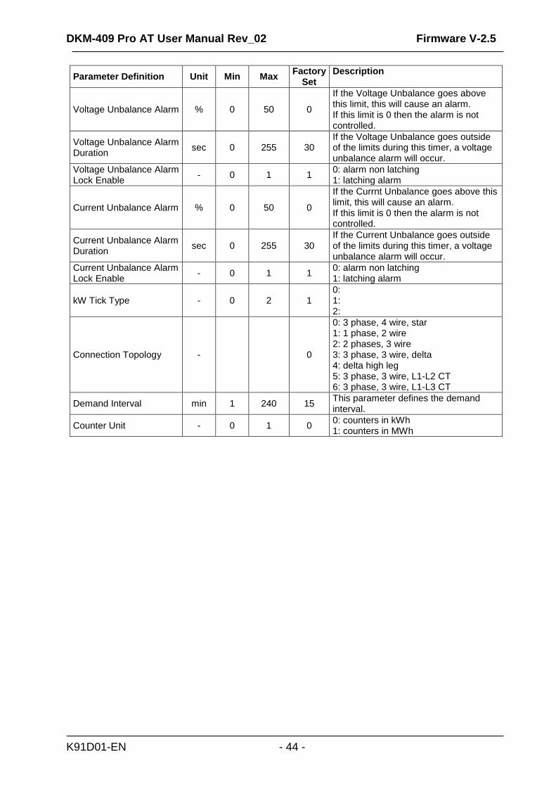
Parameter Definition Unit Min Max Factory
Set Description
Voltage Unbalance Alarm % 0 50 0
If the Voltage Unbalance goes above this limit, this will cause an alarm. If this limit is 0 then the alarm is not controlled.
Voltage Unbalance Alarm Duration
sec 0 255 30 If the Voltage Unbalance goes outside of the limits during this timer, a voltage unbalance alarm will occur.
Voltage Unbalance Alarm Lock Enable
- 0 1 1 0: alarm non latching 1: latching alarm
Current Unbalance Alarm % 0 50 0
If the Currnt Unbalance goes above this limit, this will cause an alarm. If this limit is 0 then the alarm is not controlled.
Current Unbalance Alarm Duration
sec 0 255 30 If the Current Unbalance goes outside of the limits during this timer, a voltage unbalance alarm will occur.
Current Unbalance Alarm Lock Enable
- 0 1 1 0: alarm non latching 1: latching alarm
kW Tick Type - 0 2 1 0: 1: 2:
Connection Topology - 0
0: 3 phase, 4 wire, star 1: 1 phase, 2 wire 2: 2 phases, 3 wire 3: 3 phase, 3 wire, delta 4: delta high leg 5: 3 phase, 3 wire, L1-L2 CT 6: 3 phase, 3 wire, L1-L3 CT
Demand Interval min 1 240 15 This parameter defines the demand interval.
Counter Unit - 0 1 0 0: counters in kWh 1: counters in MWh
DKM-409 Pro AT User Manual Rev_02 Firmware V-2.5
K91D01-EN - 45 -
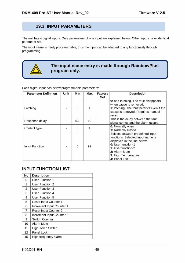
The unit has 4 digital inputs. Only parameters of one input are explained below. Other inputs have identical parameter set.
The input name is freely programmable, thus the input can be adapted to any functionality through programming.
Each digital input has below programmable parameters:
Parameter Definition Unit Min Max Factory Set
Description
Latching - 0 1
0: non-latching. The fault disappears when cause is removed. 1: latching. The fault persists even if the cause is removed. Requires manual reset.
Response delay - 0.1 10 This is the delay between the fault signal comes and the alarm occurs.
Contact type - 0 1 0: Normally open 1: Normally closed
Input Function - 0 99
Selects between predefined input functions. Selected input name is displayed in the line below. 0: User function-1 1: User function-2 2: Alarm Mute 3: High Temperature 4: Panel Lock
INPUT FUNCTION LIST
No Description
0 User Function 1
1 User Function 2
2 User Function 3
3 User Function 4
4 User Function 5
5 Reset Input Counter 1
6 Increment Input Counter 1
7 Reset Input Counter 2
8 Increment Input Counter 2
9 Switch Counter
10 Alarm Mute
11 High Temp Switch
12 Panel Lock
15 High frequency alarm
19.3. INPUT PARAMETERS
The input name entry is made through RainbowPlus program only.
DKM-409 Pro AT User Manual Rev_02 Firmware V-2.5
K91D01-EN - 46 -
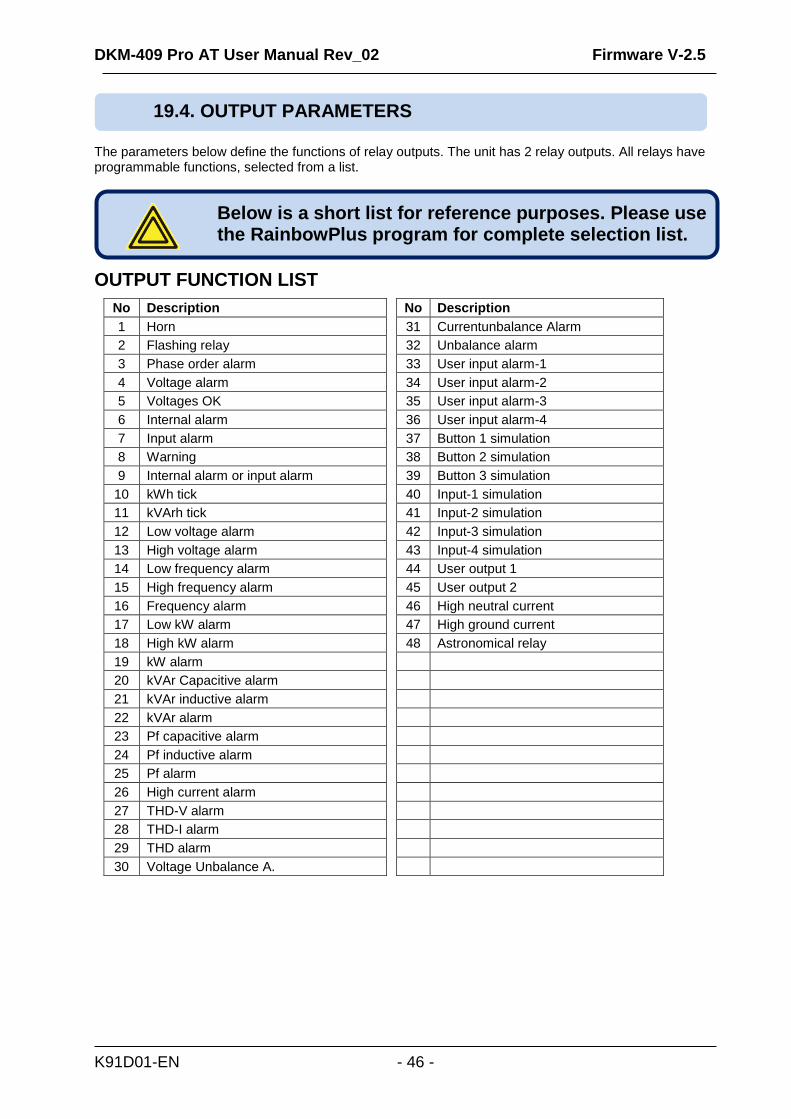
The parameters below define the functions of relay outputs. The unit has 2 relay outputs. All relays have programmable functions, selected from a list.
OUTPUT FUNCTION LIST
No Description
1 Horn
2 Flashing relay
3 Phase order alarm
4 Voltage alarm
5 Voltages OK
6 Internal alarm
7 Input alarm
8 Warning
9 Internal alarm or input alarm
10 kWh tick
11 kVArh tick
12 Low voltage alarm
13 High voltage alarm
14 Low frequency alarm
15 High frequency alarm
16 Frequency alarm
17 Low kW alarm
18 High kW alarm
19 kW alarm
20 kVAr Capacitive alarm
21 kVAr inductive alarm
22 kVAr alarm
23 Pf capacitive alarm
24 Pf inductive alarm
25 Pf alarm
26 High current alarm
27 THD-V alarm
28 THD-I alarm
29 THD alarm
30 Voltage Unbalance A.
No Description
31 Currentunbalance Alarm
32 Unbalance alarm
33 User input alarm-1
34 User input alarm-2
35 User input alarm-3
36 User input alarm-4
37 Button 1 simulation
38 Button 2 simulation
39 Button 3 simulation
40 Input-1 simulation
41 Input-2 simulation
42 Input-3 simulation
43 Input-4 simulation
44 User output 1
45 User output 2
46 High neutral current
47 High ground current
48 Astronomical relay
19.4. OUTPUT PARAMETERS
Below is a short list for reference purposes. Please use the RainbowPlus program for complete selection list.

DKM-409 Pro AT User Manual Rev_02 Firmware V-2.5
K91D01-EN - 47 -
The module provides 3 analog outputs. The measurement to output from each channel is selectable from a list. The values for 4mA and 20mA are also programmable.
A program page is reserved for each channel.
Analogue Out 1 Configuration Parameter settings for the analog output-1
Analogue Out 2 Configuration Parameter settings for the analog output-2
Analogue Out 3 Configuration Parameter settings for the analog output-3
Parameter Definition Unit Min Max Factory Set
Description
Function - 1 42
0: non-latching. The fault disappears when cause is removed. 1: latching. The fault persists even if the cause is removed. Requires manual reset.
Minimum - This is the value of the FUNCTION for 4mA output.
Maximum - This is the value of the FUNCTION for 20mA output.
The parameters below define the functions of analogue outputs. The unit has 3 analogue outputs. All analogue outputs have programmable functions with maximum and minimum values, selected from a list.
OUTPUT FUNCTION LIST
No Description
1 L1-N Voltage
2 L2-N Voltage
3 L3-N Voltage
4 L1-L2 Voltage
5 L2-L3 Voltage
6 L3-L1 Voltage
7 L1 Current
8 L2 Current
9 L3 Current
10 Neutral Current
11 Ground Current
12 L1 Active Power
13 L2 Active Power
14 L3 Active Power
15 Total Active Power
16 L1 Reactive Power
17 L2 Reactive Power
18 L3 Reactive Power
19 Total Reactive Power
20 L1 Apparent Power
No Description
21 L2 Apparent Power
22 L3 Apparent Power
23 Total Apparent Power
24 L1 Power Factor
25 L2 Power Factor
26 L3 Power Factor
27 Total Power Factor
28 Frequency
29 Supply Voltage
30 Average L-N Voltage
31 L1 power factor
32 L2 power factor
33 L3 power factor
34 Total power factor
35 Frequency
36 Supply voltage
37 Average L-N Current
38 Average L-L Voltage
39 Average L-N Current
40 L1 Q/P Ratio
No Description
41 L2 Q/P Ratio
42 L3 Q/P Ratio
43
44
45
46
47
48
49
50
51
52
53
54
55
56
57
58
59
60
19.5. ANALOGUE OUTPUTS

DKM-409 Pro AT User Manual Rev_02 Firmware V-2.5
K91D01-EN - 48 -
In this group various texts are entered. These texts appear at top of user screens, as special names for digital inputs or analyzer module names.
In this group, restarting of demand periods and setting of counter values are performed.
4 available user defined screens are configured through this menu.
There are 2 different character sizes that can be selected.
(5x7 and 10x14 pixels)
1) Please select character size with and
buttons, then press .
2) Please select the value to display through
“SELECT AN ITEM” menu, then press .
For the next item to display, the menu returns to the
character size selection menu. Above steps 1 and 2 may
be repeated until the screen is full.
As long as the user stays in the user screen menu, the
current appearance of the screen will be on display.
When all available space is occupied, the menu is
automatically exited.
If required, the menu may be exited without filling the
screeen by holding button pressed for 3 seconds.
19.6. USER INPUT STRINGS
19.7. MIN/MAX/COUNTER SET
19.8. USER SCREENS
DKM-409 Pro AT User Manual Rev_02 Firmware V-2.5
K91D01-EN - 49 -
Holds user defined device serial number.
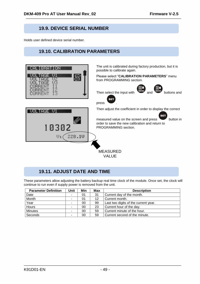
The unit is calibrated during factory production, but it is possible to calibrate again.
Please select “CALIBRATION PARAMETERS” menu from PROGRAMMING section.
Then select the input with and buttons and
press .
Then adjust the coefficient in order to display the correct
measured value on the screen and press button in
order to save the new calibration and return to
PROGRAMMING section.
These parameters allow adjusting the battery backup real time clock of the module. Once set, the clock will continue to run even if supply power is removed from the unit.
Parameter Definition Unit Min Max Description
Date - 01 31 Current day of the month.
Month - 01 12 Current month.
Year - 00 99 Last two digits of the current year.
Hours - 00 23 Current hour of the day.
Minutes - 00 59 Current minute of the hour.
Seconds - 00 59 Current second of the minute.
19.9. DEVICE SERIAL NUMBER
19.10. CALIBRATION PARAMETERS
19.11. ADJUST DATE AND TIME
MEASURED VALUE

DKM-409 Pro AT User Manual Rev_02 Firmware V-2.5
K91D01-EN - 50 -
The unit has 3 different password levels. Each password consists on a 4 digit number.
When this menu is selected, the unit will ask for confirmation.
Please adjust required selection with and buttons, then press in order to return to PROGRAMMING section.
Parameters adjusted in this section are used in the astronomical relay function.
Parameter Definition Unit Min Max Factory Set
Description
TIME SOURCE - - - RTC The unit picks up the date&time information only from the internal RTC.
LOCATION SOURCE - - - SET This parameter determines the source for geographical location information. The unit supports only manual entry.
LATITUDE degrees 66S 66N 41,000N
This parameter defines the latitude as degrees. NOTE: Sunrise and sunset cannot be calculated for latitudes beyon polar circles.
LONGITUDE degrees 180W 180E 36,444E This parameter defines the longitude in degrees.
TIME ZONE hour -12 +12 +2
The effective time zone. For eastern longitudes the sign is positive. For wastern longitudes the sign is negative. Central Europe is generally +1 time zone.
SUNRISE OFFSET minute 30 Defines the delay before sunrise that the astronomical relay will turn off.
SUNSET OFFSET minute 30 Defines the delay after sunset that the astronomical relay will turn on.
PLATE CODE - 1 100 34 Available for Turkey only. Latitudes and longitutes may be automatically selected from list.
19.12. CHANGE PASSWORD
Passwords can only be modified at factory.
19.13. RETURN TO FACTORY SETTİNGS
It is not possible to restore previous parameter settings.
19.14. LOCATION SETUP

DKM-409 Pro AT User Manual Rev_02 Firmware V-2.5
K91D01-EN - 51 -
The 1MB internal memory of the unit holds 15000 records of 64 bytes long.
The record period is adjusted by program parameter: CONTROLLER CONFIGURATION>Internal Record Timer.
Records can only be read through Modbus. Please see the MODBUS chapter for the details of record reading.
The Rainbow Plus program offers a way to read and store the internal record memory on computer disk.
Below values are recorded:
- Record date & time - Statuses of digital inputs & relay outputs - Analog Output_1 percentage - Voltages V1, V2, V3, U12, U23, U31 - Currents I1, I2, I3 - Frequency - Active powers P1, P2, P3, Ptot - Reactive powers Q1, Q2, Q3 - Total apparent power - Average power factor - Neutral current - Ground current - Alarm bits - THDs V1, V2, V3, U12, U23, U31, I1, I2, I3
20. INTERNAL RECORD MEMORY
DKM-409 Pro AT User Manual Rev_02 Firmware V-2.5
K91D01-EN - 52 -
The unit offers the possibility of MODBUS communication through below carrier: -RS485 serial port, with adjustable baud rate between 2400 and 115200 bauds
The MODBUS properties of the unit are: -Data transfer mode: RTU -Serial data: selectable baud rate, 8 bit data, no parity, 1 bit stop -Supported functions: -Function 3 (Read multiple registers) -Function 6 (Write single register)
-Function 16 (Write multiple registers) Each register consists of 2 bytes (16 bits). A larger data structure will contain multiple registers. The Modbus communications requires a slave address to be assigned to each device in the Modbus network. This address ranges between 1 and 240 and allows the addressing of different slave devices in the same network.
Modbus Slave Address: may be set between 1 and 240 RS-485 Enable: must be set to 1 (or checkbox enabled) RS-485 Baud Rate: selectable between 2400 and 115200 bauds. All devices in the same network must use the same Baud Rate. Selecting a higher baud rate will allow faster communication, but will reduce the communication distance. Selecting a lower baud rate will increase the communication distance, but will cause slower response times. Typically 9600 bauds will allow 1200m distance with special balanced 120 ohms cable.
16bit variables: These variables are stored in a single register. Bit_0 denotes the LSB and bit 15 denotes the MSB. 32 bit variables: These variables are stored in 2 consecutive registers. The high order 16 bits are in the first register and the low order 16 bits are in the second register Bit arrays: Arrays larger than 16 bits are stored in multiple registers. The LSB of the first register is bit_0. The MSB of the first register is bit_15. The LSB of the second register is bit_16. The MSB of the second register is bit_31, and so on.
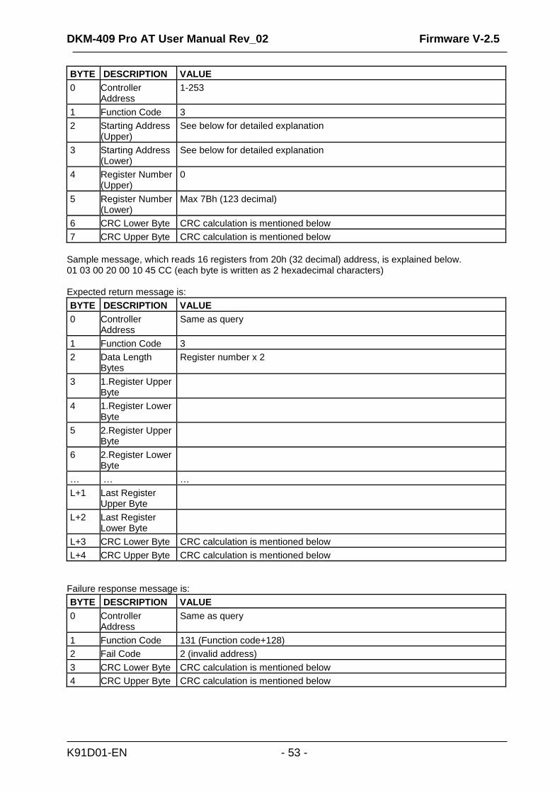
Data read can be achieved by using function 03 (read multiple register). MODBUS master device sends query. Respond can be either requested data or failure message including reading fail. 123 Registers can be read by single message. If a single message includes query for more than 123 registers, first 123 registers will be returned. Message structure can be seen below.
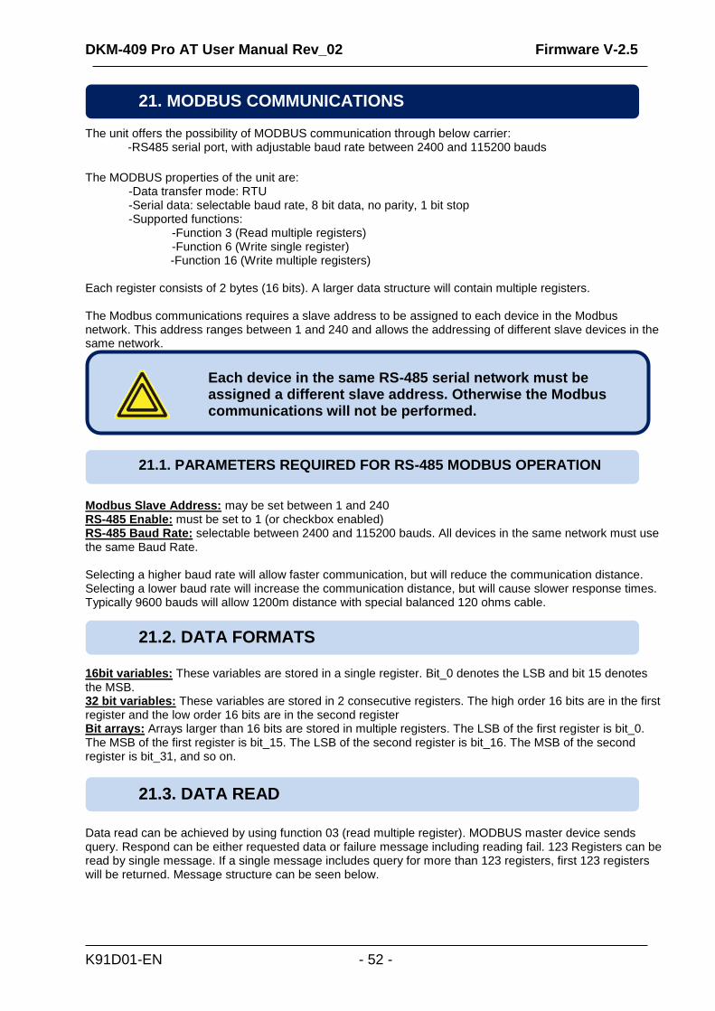
21. MODBUS COMMUNICATIONS
Each device in the same RS-485 serial network must be assigned a different slave address. Otherwise the Modbus communications will not be performed.
21.1. PARAMETERS REQUIRED FOR RS-485 MODBUS OPERATION
21.2. DATA FORMATS
21.3. DATA READ
DKM-409 Pro AT User Manual Rev_02 Firmware V-2.5
K91D01-EN - 53 -
BYTE DESCRIPTION VALUE
0 Controller Address
1-253
1 Function Code 3
2 Starting Address (Upper)
See below for detailed explanation
3 Starting Address (Lower)
See below for detailed explanation
4 Register Number (Upper)
0
5 Register Number (Lower)
Max 7Bh (123 decimal)
6 CRC Lower Byte CRC calculation is mentioned below
7 CRC Upper Byte CRC calculation is mentioned below
Sample message, which reads 16 registers from 20h (32 decimal) address, is explained below. 01 03 00 20 00 10 45 CC (each byte is written as 2 hexadecimal characters) Expected return message is:
BYTE DESCRIPTION VALUE
0 Controller Address
Same as query
1 Function Code 3
2 Data Length Bytes
Register number x 2
3 1.Register Upper Byte
4 1.Register Lower Byte
5 2.Register Upper Byte
6 2.Register Lower Byte
… … …
L+1 Last Register Upper Byte
L+2 Last Register Lower Byte
L+3 CRC Lower Byte CRC calculation is mentioned below
L+4 CRC Upper Byte CRC calculation is mentioned below
Failure response message is:
BYTE DESCRIPTION VALUE
0 Controller Address
Same as query
1 Function Code 131 (Function code+128)
2 Fail Code 2 (invalid address)
3 CRC Lower Byte CRC calculation is mentioned below
4 CRC Upper Byte CRC calculation is mentioned below

DKM-409 Pro AT User Manual Rev_02 Firmware V-2.5
K91D01-EN - 54 -
Writing register values can be accomplished by using function 06 (write single register). Single message can write only one register. MODBUS master device sends query, which includes data to be written. Respond can be either a message that indicates writing process successful, or failure message including writing fail.
BYTE DESCRIPTION VALUE
0 Controller Address 1 to 253
1 Function Code 6
2 Register Address Upper Writeable registers are listed below
3 Register Address Lower Writeable registers are listed below
4 Data Upper Byte
5 Data Lower Byte
6 CRC Lower Byte CRC calculation is mentioned below
7 CRC Upper Byte CRC calculation is mentioned below
Sample message, which writes 0010h value to 40h (64 decimal) address, is explained below. 01 06 00 40 00 10 89 D2 (each byte is written as 2 hexadecimal characters) Expected response is same as query:
BYTE DESCRIPTION VALUE
0 Controller Address 1 to 253
1 Function Code 6
2 Register Address Upper Writeable registers are listed below
3 Register Address Lower Writeable registers are listed below
4 Data Upper Byte
5 Data Lower Byte
6 CRC Lower Byte CRC calculation is mentioned below
7 CRC Upper Byte CRC calculation is mentioned below
Failure response message is:
BYTE DESCRIPTION VALUE
0 Controller Address
Same as query
1 Function Code 134 (Function code + 128)
2 Fail Code 2: Invalid Address
10: Write Protection
3 CRC Lower Byte CRC calculation is mentioned below
4 CRC Upper Byte CRC calculation is mentioned below
21.4. DATA WRITE

DKM-409 Pro AT User Manual Rev_02 Firmware V-2.5
K91D01-EN - 55 -
A method to create CRC is explained as follows,
1) Find one 16-bit free register and set all its bits to 1, which will be called as CRC. 2) Perform Exclusive OR operation between Lower byte of CRC, and First byte of the message
(function code). Write the result at CRC register. 3) Identify LSB of CRC, shift CRC register to 1 bit right. Modify MSB as 0. 4) Perform Exclusive OR operation between CRC and A001h, if LSB is 1. 5) Repeat 3. And 4. steps until 8 bit is shifted. 6) Repeat 2. 3. 4. 5. Steps for next 8 bit. 7) Remained value of CRC register is called CRC. 8) Add CRC to the message so that lower byte is sent first. Algorithm should return correct CRC for
messages below. 01 03 00 20 00 10 45 CC 01 06 00 40 00 10 89 D2
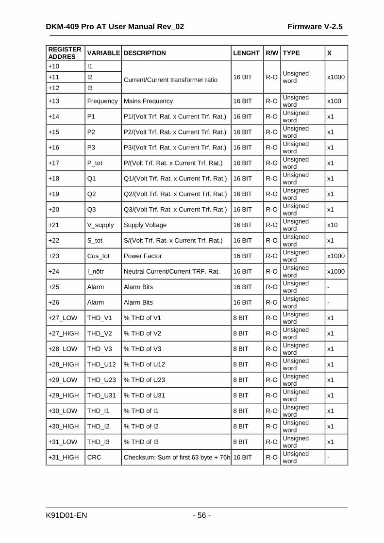
The unit has 1 MB internal record memory, consisting of 15000 blocks of 64 bytes. In order to read the record memory, record number (0…14999) should be written at address “16389”. Then the related record can be read from address “4096”.
REGISTER ADDRES
VARIABLE
DESCRIPTION
LENGHT
R/W
TYPE
X
+0 +1
Date-Time
32 bit date-time information Bit_0..4: second/2 (0-29) Bit_5..10: minute (0-59) Bit_11..15: hour (0-23) Bit_16..20: day (1-31) Bit_21..24: month (1-12) Bit_25..31: year-2000 (0..127=2000..2127)
32 BIT
R-O
bitmap
+2_LOW Type Log Type 8 BIT R-O unsigned byte -
+2_HIGH Argument Log Additional Info 8 BIT R-O unsigned byte -
+3_LOW
Input- Output Status
Bit_0..4: digital input statuses Bit_5..7: digital output statuses
8 BIT
R-O
bitmap
100
+3_HIGH - Not Used
+4 V1
Voltage/Voltage transformer ratio
16 BIT
R-O
Unsigned word
x1
+5 V2
+6 V3
+7 U12
+8 U23
+9 U31
21.5. CRC CALCULATION
21.6. INTERNAL RECORD MEMORY STRUCTURE
DKM-409 Pro AT User Manual Rev_02 Firmware V-2.5
K91D01-EN - 56 -
REGISTER ADDRES
VARIABLE
DESCRIPTION
LENGHT
R/W
TYPE
X
+10 I1 Current/Current transformer ratio
16 BIT
R-O
Unsigned word
x1000 +11 I2
+12 I3
+13
Frequency
Mains Frequency
16 BIT
R-O Unsigned word
x100
+14
P1
P1/(Volt Trf. Rat. x Current Trf. Rat.)
16 BIT
R-O Unsigned word
x1
+15
P2
P2/(Volt Trf. Rat. x Current Trf. Rat.)
16 BIT
R-O Unsigned word
x1
+16
P3
P3/(Volt Trf. Rat. x Current Trf. Rat.)
16 BIT
R-O Unsigned word
x1
+17
P_tot
P/(Volt Trf. Rat. x Current Trf. Rat.)
16 BIT
R-O Unsigned word
x1
+18
Q1
Q1/(Volt Trf. Rat. x Current Trf. Rat.)
16 BIT
R-O Unsigned word
x1
+19
Q2
Q2/(Volt Trf. Rat. x Current Trf. Rat.)
16 BIT
R-O Unsigned word
x1
+20
Q3
Q3/(Volt Trf. Rat. x Current Trf. Rat.)
16 BIT
R-O Unsigned word
x1
+21
V_supply
Supply Voltage
16 BIT
R-O Unsigned word
x10
+22
S_tot
S/(Volt Trf. Rat. x Current Trf. Rat.)
16 BIT
R-O Unsigned word
x1
+23
Cos_tot
Power Factor
16 BIT
R-O Unsigned word
x1000
+24
I_nötr
Neutral Current/Current TRF. Rat.
16 BIT
R-O Unsigned word
x1000
+25
Alarm
Alarm Bits
16 BIT
R-O Unsigned word
-
+26
Alarm
Alarm Bits
16 BIT
R-O Unsigned word
-
+27_LOW
THD_V1
% THD of V1
8 BIT
R-O Unsigned word
x1
+27_HIGH
THD_V2
% THD of V2
8 BIT
R-O Unsigned word
x1
+28_LOW
THD_V3
% THD of V3
8 BIT
R-O Unsigned word
x1
+28_HIGH
THD_U12
% THD of U12
8 BIT
R-O Unsigned word
x1
+29_LOW
THD_U23
% THD of U23
8 BIT
R-O Unsigned word
x1
+29_HIGH
THD_U31
% THD of U31
8 BIT
R-O Unsigned word
x1
+30_LOW
THD_I1
% THD of I1
8 BIT
R-O Unsigned word
x1
+30_HIGH
THD_I2
% THD of I2
8 BIT
R-O Unsigned word
x1
+31_LOW
THD_I3
% THD of I3
8 BIT
R-O Unsigned word
x1
+31_HIGH
CRC
Checksum: Sum of first 63 byte + 76h
16 BIT
R-O Unsigned word
-

DKM-409 Pro AT User Manual Rev_02 Firmware V-2.5
K91D01-EN - 57 -
REGISTER ADDRES
VARIABLE
DESCRIPTION
LENGHT
R/W
TYPE
X
16384 Password Programming Password 16 BIT W-O Unsigned
word
x1
16385 Button Button Simulation
BIT0: Set
BIT1: Up Arrow
BIT2: Down Arrow
16 BIT W-O Unsigned
word
x1
16386 Factory Return to factory settings 16 BIT W-O Unsigned
word
x1
16387 Counter Reset
Reset All Counters 16 BIT W-O Unsigned
word
x1
16388 Read_Flsh Write on internal flash memory 16 BIT W-O Unsigned
word
x1
16389
Read_Rec Copy record to the BUFFER
16 BIT
W-O
Unsigned Word
x1
16390
BOOT BOOT JUMP
16 BIT
W-O
Unsigned Word
x1
16391 Relay Remote control relay func. Write 16 BIT W-O Unsigned
word
x1
REGISTER ADDRES
VARIABLE
DESCRIPTION
LENGHT
R/W
TYPE
X
8192 Year Year (0-4096) 16 BIT R/W Unsigned
word
x1
8193 Month Month (1-12) 16 BIT R/W Unsigned
word
x1
8194 Day_Month Day (1-31) 16 BIT R/W Unsigned
word
x1
8196 Hour Hour (0-23) 16 BIT R/W Unsigned
word
x1
8197 Minute Minute (0-59) 16 BIT R/W Unsigned
word
x1
8198 Second Second (0-59) 16 BIT R/W Unsigned
word
x1
8199 Latitude Latitude (+- 66.499) Negative latitude means “South”
32 BIT R-O Signed
long
x1000
8201 Longitude Longitude (+- 179.999) Negative longitude means “West”
32 BIT R-O Signed
long
x1000
21.7. COMMANDS
21.8. REAL TIME CLOCK
DKM-409 Pro AT User Manual Rev_02 Firmware V-2.5
K91D01-EN - 58 -
REGISTER
ADDRESS
VARIABLE DESCRIPTION LENGTH R/W TYPE X
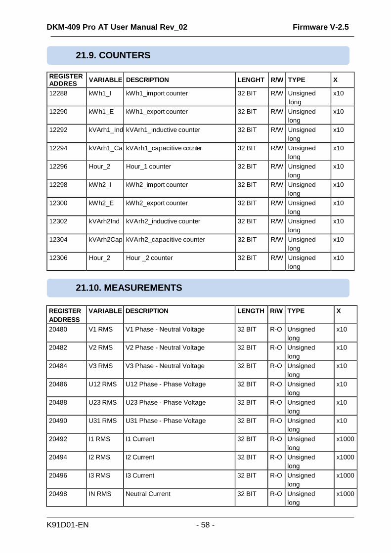
20480 V1 RMS V1 Phase - Neutral Voltage 32 BIT R-O Unsigned
long
x10
20482 V2 RMS V2 Phase - Neutral Voltage 32 BIT R-O Unsigned
long
x10
20484 V3 RMS V3 Phase - Neutral Voltage 32 BIT R-O Unsigned
long
x10
20486 U12 RMS U12 Phase - Phase Voltage 32 BIT R-O Unsigned
long
x10
20488 U23 RMS U23 Phase - Phase Voltage 32 BIT R-O Unsigned
long
x10
20490 U31 RMS U31 Phase - Phase Voltage 32 BIT R-O Unsigned
long
x10
20492 I1 RMS I1 Current 32 BIT R-O Unsigned
long
x1000
20494 I2 RMS I2 Current 32 BIT R-O Unsigned
long
x1000
20496 I3 RMS I3 Current 32 BIT R-O Unsigned
long
x1000
20498 IN RMS Neutral Current 32 BIT R-O Unsigned
long
x1000
REGISTER ADDRES
VARIABLE
DESCRIPTION
LENGHT
R/W
TYPE
X
12288 kWh1_I kWh1_import counter 32 BIT R/W Unsigned
long
x10
12290 kWh1_E kWh1_export counter 32 BIT R/W Unsigned
long
x10
12292 kVArh1_Ind kVArh1_inductive counter 32 BIT R/W Unsigned
long
x10
12294 kVArh1_Ca kVArh1_capacitive counter 32 BIT R/W Unsigned
long
x10
12296 Hour_2 Hour_1 counter 32 BIT R/W Unsigned
long
x10
12298 kWh2_I kWh2_import counter 32 BIT R/W Unsigned
long
x10
12300 kWh2_E kWh2_export counter 32 BIT R/W Unsigned
long
x10
12302 kVArh2Ind kVArh2_inductive counter 32 BIT R/W Unsigned
long
x10
12304 kVArh2Cap kVArh2_capacitive counter 32 BIT R/W Unsigned
long
x10
12306 Hour_2 Hour _2 counter 32 BIT R/W Unsigned
long
x10
21.9. COUNTERS
21.10. MEASUREMENTS

DKM-409 Pro AT User Manual Rev_02 Firmware V-2.5
K91D01-EN - 59 -
REGISTER
ADDRESS
VARIABLE DESCRIPTION LENGTH R/W TYPE X
20502 P1 Phase 1 Active Power (kW) 32 BIT R-O Signed long x100
20504 P2 Phase 2 Active Power (kW) 32 BIT R-O Signed long x100
20506 P3 Phase 3 Active Power (kW) 32 BIT R-O Signed long x100
20508 ∑P Total Active Power (kW) 32 BIT R-O Signed long x100
20510 Q1 Phase 1 Reactive Power (kVAr) 32 BIT R-O Signed long x100
20512 Q2 Phase 2 Reactive Power (kVAr) 32 BIT R-O Signed long x100
20514 Q3 Phase 3 Reactive Power (kVAr) 32 BIT R-O Signed long x100
20516 ∑Q Total Reactive Power (kVAr) 32 BIT R-O Signed long x100
20518 S1 Phase 1 Apparent Power (kVA) 32 BIT R-O Signed long x100
20520 S2 Phase 2 Apparent Power (kVA) 32 BIT R-O Signed long x100
20522 S3 Phase 3 Apparent Power (kVA) 32 BIT R-O Signed long x100
20524 ∑S Total Apparent Power (kVA) 32 BIT R-O Signed long x100
20526 Cosф 1 Phase 1 Power Factor 16 BIT R-O Signed word x1000
20527 Cosф 2 Phase 2 Power Factor 16 BIT R-O Signed word x1000
20528 Cosф 3 Phase 3 Power Factor 16 BIT R-O Signed word x1000
20529 ∑Cosф Total Power Factor 16 BIT R-O Signed word x1000
20530 Freq Frequency 16 BIT R-O Unsigned word x100
20532 Va RMS Average Phase - Neutral Voltage 32 BIT R-O Unsigned
long
x10
20534 Ua RMS Average Phase - Phase Voltage 32 BIT R-O Unsigned
long
x10
20536 Ia RMS Average Current 32 BIT R-O Unsigned
long
x1000
20542 Dig-in Digital Inputs
BIT0: IN1
BIT1: IN2
BIT2: IN3
BIT3: IN4
16 BIT R-O 16 bit bitmap -
20543 Dig-out Digital Outputs
BIT0: RL1
BIT1: RL2
16 BIT R-O 16 bit bitmap -
21047 Scope_ch Oscilloscope Channel Number 16 BIT R-O Unsigned word -
21048- 21147
Scope Oscilloscope Data 16 BIT R-O Signed word x1
21148- 21151
Relay F. Relay Function Status Bits 16 BIT R-O Array 4x16 bit -
21152 Anl_1_Val Analogue Output 1 ADC (mA) 16 BIT R-O Unsigned word x1
21153 Anl_2_Val Analogue Output 2 ADC (mA) 16 BIT R-O Unsigned word x1
21154 Anl_3_Val Analogue Output 3 ADC (mA) 16 BIT R-O Unsigned word x1
21155 Anl_1_Rat Analogue Out 1 % 16 BIT R-O Unsigned word x100
21156 Anl_2_Rat Analogue Out 2 % 16 BIT R-O Unsigned word x100
21157 Anl_3_Rat Analogue Out 3 % 16 BIT R-O Unsigned word x100
21158 SF_Page Last Record Number 16 BIT R-O Unsigned word x1
21159 Event_No Last Event Record Number 16 BIT R-O Unsigned word x1
21160 Reset_sta Last Reset Cause 16 BIT R-O 16 bit bitmap -
21161 Topology Topology
0: 3 Phase 4 Wire Star
1: 1 Phase 2 Wire
16 BIT R-O Unsigned word x1

DKM-409 Pro AT User Manual Rev_02 Firmware V-2.5
K91D01-EN - 60 -
REGISTER
ADDRESS
VARIABLE DESCRIPTION LENGTH R/W TYPE X
2: 2 Phase 3 Wire
3: 3 Phase 4 Wire Delta
4: Delta High Leg
5: 3 Phase 3 Wire L1 L2 CT
6: 3 Phase 3 Wire L1 L3 CT
21162 Dev_Type Device Model Number 16 BIT R-O Unsigned word x1
21163 SW_Vers Software Version 16 BIT R-O Unsigned word x1
21164 HW_Cnf Hardware
Configuration
16 BIT R-O Unsigned Word
x1
21165 Flash_sta Flash Write Status 16 BIT R-O 16 bit bitmap -
21166 Ev_RD_sta Event Log Read Status 16 BIT R-O 16 bit bitmap
-
21167 Unlock_cnt Password Unlock Counter 16 BIT R-O Unsigned Word
x1
21168-
21679
LCD_buf LCD Buffer 512x16 BIT
R-O Array 128x64 BIT
-
21680 LCD_sta LCD Status 16 BIT R-O 16 bit bitmap -
21681 Warning Not-Used 16 BIT R-O 16 bit bitmap -
21682 Alarm Alarm Function Bits 0-15 16 BIT R-O 16 bit bitmap -
21683 Alarm Alarm Function Bits 16-31 16 BIT R-O 16 bit bitmap -
21686- 21691
Unique ID Unit ID number 96 BIT R-O 6x16bit -
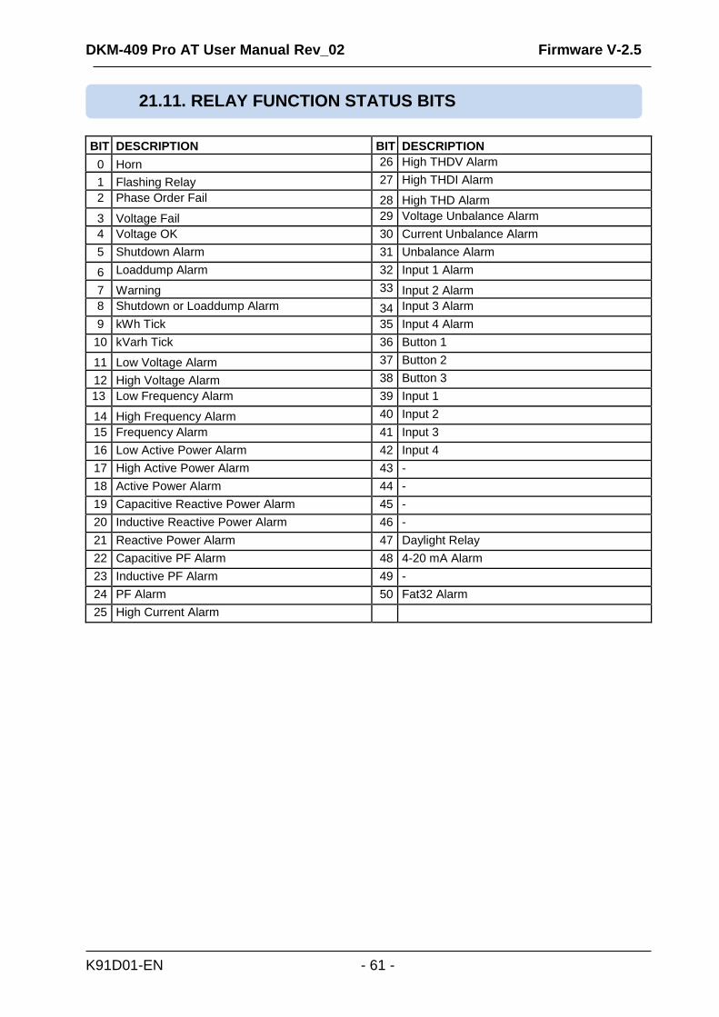
DKM-409 Pro AT User Manual Rev_02 Firmware V-2.5
K91D01-EN - 61 -
BIT DESCRIPTION BIT DESCRIPTION
0 Horn 26 High THDV Alarm
1 Flashing Relay 27 High THDI Alarm
2 Phase Order Fail 28 High THD Alarm
3 Voltage Fail 29 Voltage Unbalance Alarm
4 Voltage OK 30 Current Unbalance Alarm
5 Shutdown Alarm 31 Unbalance Alarm
6 Loaddump Alarm 32 Input 1 Alarm
7 Warning 33 Input 2 Alarm
8 Shutdown or Loaddump Alarm 34 Input 3 Alarm
9 kWh Tick 35 Input 4 Alarm
10 kVarh Tick 36 Button 1
11 Low Voltage Alarm 37 Button 2
12 High Voltage Alarm 38 Button 3
13 Low Frequency Alarm 39 Input 1
14 High Frequency Alarm 40 Input 2
15 Frequency Alarm 41 Input 3
16 Low Active Power Alarm 42 Input 4
17 High Active Power Alarm 43 -
18 Active Power Alarm 44 -
19 Capacitive Reactive Power Alarm 45 -
20 Inductive Reactive Power Alarm 46 -
21 Reactive Power Alarm 47 Daylight Relay
22 Capacitive PF Alarm 48 4-20 mA Alarm
23 Inductive PF Alarm 49 -
24 PF Alarm 50 Fat32 Alarm
25 High Current Alarm
21.11. RELAY FUNCTION STATUS BITS

DKM-409 Pro AT User Manual Rev_02 Firmware V-2.5
K91D01-EN - 62 -
BIT DESCRIPTION BIT DESCRIPTION
0 High Voltage 16 Input_1 Alarm
1 Low Voltage 17 Input_2 Alarm
2 High Frequency 18 Input_3 Alarm
3 Low Frequency 19 Input_4 Alarm
4 High kW 20 High Neutral Current
5 Low kW 21
6 High kVAr 22
7 Low kVAr 23
8 High Cos 24
9 Low Cos 25
10 High Current 26
11 High THD_V 27
12 High THD_V 28
13 Voltage Unbalance 29
14 Current Unbalance 30
15 Phase Order Error 31
21.12. ALARM FUNCTION BITS

DKM-409 Pro AT User Manual Rev_02 Firmware V-2.5
K91D01-EN - 63 -
The unit measures up to 50 harmonics and THD values of 10 channels. Harmonics of each channel read from a memory location, which has 50 registers. Memory structure of each channel have same properties.
REGISTER ADDRES
VARIABLE
DESCRIPTION
LENGHT
R/W
TYPE
X
20547 Harm_V1 V1 Harmonics 50x16 bit R-O Array 50x16bit x10
20597 Harm_V2 V2 Harmonics 50x16 bit R-O Array 50x16bit x10
20647 Harm_V3 V3 Harmonics 50x16 bit R-O Array 50x16bit x10
20697 Harm_U12 U12 Harmonics 50x16 bit R-O Array 50x16bit x10
20747 Harm_U23 U23 Harmonics 50x16 bit R-O Array 50x16bit x10
20797 Harm_U31 U31 Harmonics 50x16 bit R-O Array 50x16bit x10
20847 Harm_I1 I1 Harmonics 50x16 bit R-O Array 50x16bit x10
20897 Harm_I2 I2 Harmonics 50x16 bit R-O Array 50x16bit x10
20947 Harm_I3 I3 Harmonics 50x16 bit R-O Array 50x16bit x10
20997 Harm_In In Harmonics 50x16 bit R-O Array 50x16bit x10
Stored register addresses can be found by adding offsets to base addresses given above.
REGISTER
ADDRESS
VARIABLE DESCRIPTION LENGTH R/W TYPE X
+0 1.
Harmonic
1. Harmonic (%) 16 BIT R-O unsigned word x10
+1 3. Harmonic
3. Harmonic (%) 16 BIT R-O unsigned word x10
.... .... .... … … … …
.... .... .... … … … …
+46 48. Harmonic
48. Harmonic (%) 16 BIT R-O unsigned word x10
+47 49. Harmonic
49. Harmonic (%) 16 BIT R-O unsigned word x10
+48 - Not-Used 16 BIT R-O unsigned word x10
+49 THD Total Hamornic Distortion (%) 16 BIT R-O unsigned word x10
21.13. HARMONIC MEASUREMENTS
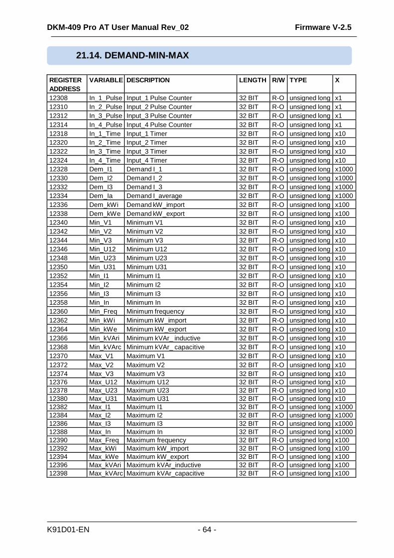
DKM-409 Pro AT User Manual Rev_02 Firmware V-2.5
K91D01-EN - 64 -
REGISTER
ADDRESS
VARIABLE DESCRIPTION LENGTH R/W TYPE X
12308 In_1_Pulse Input_1 Pulse Counter 32 BIT R-O unsigned long x1
12310 In_2_Pulse Input_2 Pulse Counter 32 BIT R-O unsigned long x1
12312 In_3_Pulse Input_3 Pulse Counter 32 BIT R-O unsigned long x1
12314 In_4_Pulse Input_4 Pulse Counter 32 BIT R-O unsigned long x1
12318 In_1_Time Input_1 Timer 32 BIT R-O unsigned long x10
12320 In_2_Time Input_2 Timer 32 BIT R-O unsigned long x10
12322 In_3_Time Input_3 Timer 32 BIT R-O unsigned long x10
12324 In_4_Time Input_4 Timer 32 BIT R-O unsigned long x10
12328 Dem_I1 Demand I_1 32 BIT R-O unsigned long x1000
12330 Dem_I2 Demand I_2 32 BIT R-O unsigned long x1000
12332 Dem_I3 Demand I_3 32 BIT R-O unsigned long x1000
12334 Dem_Ia Demand I_average 32 BIT R-O unsigned long x1000
12336 Dem_kWi Demand kW_import 32 BIT R-O unsigned long x100
12338 Dem_kWe Demand kW_export 32 BIT R-O unsigned long x100
12340 Min_V1 Minimum V1 32 BIT R-O unsigned long x10
12342 Min_V2 Minimum V2 32 BIT R-O unsigned long x10
12344 Min_V3 Minimum V3 32 BIT R-O unsigned long x10
12346 Min_U12 Minimum U12 32 BIT R-O unsigned long x10
12348 Min_U23 Minimum U23 32 BIT R-O unsigned long x10
12350 Min_U31 Minimum U31 32 BIT R-O unsigned long x10
12352 Min_I1 Minimum I1 32 BIT R-O unsigned long x10
12354 Min_I2 Minimum I2 32 BIT R-O unsigned long x10
12356 Min_I3 Minimum I3 32 BIT R-O unsigned long x10
12358 Min_In Minimum In 32 BIT R-O unsigned long x10
12360 Min_Freq Minimum frequency 32 BIT R-O unsigned long x10
12362 Min_kWi Minimum kW_import 32 BIT R-O unsigned long x10
12364 Min_kWe Minimum kW_export 32 BIT R-O unsigned long x10
12366 Min_kVAri Minimum kVAr_ inductive 32 BIT R-O unsigned long x10
12368 Min_kVArc Minimum kVAr_ capacitive 32 BIT R-O unsigned long x10
12370 Max_V1 Maximum V1 32 BIT R-O unsigned long x10
12372 Max_V2 Maximum V2 32 BIT R-O unsigned long x10
12374 Max_V3 Maximum V3 32 BIT R-O unsigned long x10
12376 Max_U12 Maximum U12 32 BIT R-O unsigned long x10
12378 Max_U23 Maximum U23 32 BIT R-O unsigned long x10
12380 Max_U31 Maximum U31 32 BIT R-O unsigned long x10
12382 Max_I1 Maximum I1 32 BIT R-O unsigned long x1000
12384 Max_I2 Maximum I2 32 BIT R-O unsigned long x1000
12386 Max_I3 Maximum I3 32 BIT R-O unsigned long x1000
12388 Max_In Maximum In 32 BIT R-O unsigned long x1000
12390 Max_Freq Maximum frequency 32 BIT R-O unsigned long x100
12392 Max_kWi Maximum kW_import 32 BIT R-O unsigned long x100
12394 Max_kWe Maximum kW_export 32 BIT R-O unsigned long x100
12396 Max_kVAri Maximum kVAr_inductive 32 BIT R-O unsigned long x100
12398 Max_kVArc Maximum kVAr_capacitive 32 BIT R-O unsigned long x100
21.14. DEMAND-MIN-MAX
DKM-409 Pro AT User Manual Rev_02 Firmware V-2.5
K91D01-EN - 65 -
The unit conforms to the EU directives
-2006/95/EC (low voltage)
-2004/108/EC (electro-magnetic compatibility)
Norms of reference:
EN 61010 (safety requirements)
EN 61326 (EMC requirements)
The CE mark indicates that this product complies with the European requirements for safety, health
environmental and customer protection.
UL / CSA Conformity: UL 61010-1, 3rd Edition, 2012-05, CAN/CSA-C22.2 File: E475547, Vol. D1
Wipe the unit, if necessary with a soft damp cloth. Do not use chemical agents
Following DIRECTIVE 2002/96/EC OF THE EUROPEAN PARLIAMENT AND OF THE COUNCIL
of 27 January 2003 on waste electrical and electronic equipment (WEEE), this unit should be stored and disposed separately from the usual waste.
The european ROHS directive restricts and prohibits the use of some chemical materials in electronic devices.
Following the “DIRECTIVE 2011/65/EU OF THE EUROPEAN PARLIAMENT AND OF THE COUNCIL of 8 June 2011 on the restriction of the use of certain hazardous substances in electrical and electronic equipment”, this product is listed in annex-I under category: “Monitoring and control instruments including industrial monitoring and control instruments” and exempted from ROHS directive. However Datakom is not using any ROHS uncompliant electronic components in the production. Only the solder contains lead. The switching to unleaded soldering is in progress.
22. DECLARATION OF CONFORMITY
23. MAINTENANCE
DO NOT OPEN THE UNIT !
There are NO serviceable parts inside the unit.
24. DISPOSAL OF THE UNIT
25. ROHS COMPLIANCE

DKM-409 Pro AT User Manual Rev_02 Firmware V-2.5
K91D01-EN - 66 -
KW and cosΦ readings are faulty although the Amp readings are correct: -Current transformers are not connected to the correct inputs or some of the CTs are connected with reverse polarity. Determine the correct connections of each individual CT in order to obtain correct KW and cosΦ for the related phase, and then connect all CTs. Please review chapter “AC CURRENT INPUTS”
The unit is inoperative: Measure the supply voltage between supply terminals. Check that the unit’s supply voltage is adequate to operating conditions. If OK, turn all fuses off, then turn all the fuses on, starting from the supply fuse. Then test the unit again.
Some program parameters are skipped: These parameters are reserved for factory setting and cannot be modified.
Short circuit outputs of unused Current Transformers.
26. TROUBLESHOOTING GUIDE
Below is a basic list of most often encountered troubles. More detailed investigation may be required in some cases.