diy quilting machine
TRANSCRIPT
8/2/2019 DIY Quilting Machine
http://slidepdf.com/reader/full/diy-quilting-machine 1/32
Copyright 2008 Douglas A. Kerr. May be reproduced and/or distributed but only intact, including this
notice. Brief excerpts may be reproduced with credit.
A Modern Automated Machine Quilting System
Douglas A. Kerr
Issue 1.1
October 23, 2008
ABSTRACT
A quilt is a fabric item, often in the form of a bed covering, with twofabric layers between which is a layer of insulating “batting”. In one
style, the three layers are held together by a pattern of continuous
stitching, a process known as quilting. This may be efficiently applied
by a quilting machine, in which a sewing machine (“sewing head”)
travels on a bidirectional carriage system over a portion of the entire
quilt. In an automated machine quilting system, the sewing head is
driven by a computer-controlled servo system so as to automatically
execute the desired pattern. In this article we describe a modern
automated machine quilting system utilizing a newly introduced
sewing head and a mature commercially-available PC-based computer
control system.
BACKGROUND
Quilts
A quilt is a fabric item often intended for use as a bed covering, but
which we may often find used as a “lap robe” or even as a decorative
wall hanging.
A quilt comprises two fabric layers (the “top” and the “back”)
between which is sandwiched a layer of insulated batting, typicallycotton, polyester, or wool, or a blend of these.
The top is ordinarily decorative. It may be made of a single piece (or
only a few joined pieces, if needed to provide the desired width, or to
implement a border) of printed or dyed fabric, spoken of as “whole
cloth” construction.
More commonly, the top is “pieced”: composed of numerous small
pieces of cloth of various colors or patterns, sewn together. A
complex pieced top may comprise several thousand individual pieces.
The piecing may either be done by hand stitching or with a sewingmachine. Sometimes embroidery or appliqué work is included on either
a whole cloth or pieced top.
The back is ordinarily of whole cloth construction, although rarely a
pieced back is used as well.
8/2/2019 DIY Quilting Machine
http://slidepdf.com/reader/full/diy-quilting-machine 2/32
A Modern Automated Machine Quilting System Page 2
The quilt is usually held together by one of two techniques:
• The quilt may be “tied”, held together in numerous places with
lengths of thread, cord, yarn, or ribbon passing through the quilt and
tied, usually with the free ends extending for decorative effect.
• The quilt may be “quilted”, held together by through stitching,
usually in a decorative pattern, extending across its entire surface.(Thus we encounter the dual usage of the word “quilting”, both (a)
meaning the overall process of making a quilt and (b) meaning the
stitching used to hold the quilt together and the process of applying
it.) The quilting process is a major component of the overall artistic
content of a completed quilt.
Quilting can be performed in several ways:
• By hand with the quilt in the lap of the artisan, on a table, or held by
a “quilting frame”.
• On a conventional sewing machine. This is only practical for small
quilts, since to stitch in the interior of the quilt a substantial amount
of the surrounding fabric needs to be rolled up or folded within the
throat of the sewing machine.
• On a quilting machine, on which a sewing machine (often called here
a “sewing head”, and often of a special design) moves across the
quilt on a bidirectional carriage. We will discuss this mode in detail in
the section to follow.
The quilting machine
A quilting machine comprises two major portions, the quilting machine
frame and the sewing head. The three fabric layers of the quilt, the
top, back, and batting, are each rolled up on a long tubular spindle.1 2
The spindles are mounted across the front of the frame. A fourth
spindle, on which the completed quilt will be progressively wound, is
mounted toward the rear.
The sewing head is on a bidirectional carriage, which can move across
the entire width of the quilt on the frame and as well from front to
rear over a modest distance. The takeup spindle is within the throat
opening of the head.
1 Often called “rollers”, “tubes” or “poles”
2 Sometimes the batting is just piled on the floor or on a shelf under the frame, or
pulled from a “mill roll” on an axle under the frame.
8/2/2019 DIY Quilting Machine
http://slidepdf.com/reader/full/diy-quilting-machine 3/32
A Modern Automated Machine Quilting System Page 3
The head is guided, either manually or automatically, to stitch a
“swath” of the pattern extending across the width of the quilt. When
one swath is finished, some of the completed portion of the quilt is
rolled onto the takeup spindle, drawing additional fabric from the three
supply spindles.
The movement of the head in the fore-and-aft direction is limited by
the presence of the takeup spindle, with its roll of completed quilt,
within the throat of the head. As the process nears its end, the roll of
completed quilt may attain a diameter of 4” or greater. For a sewing
head with a nominal throat depth of 9” (typical of even larger-size
“domestic” sewing machines, often used as sewing heads), the
motion may be limited to perhaps 3-1/2”. Thus, each swath can only
embrace perhaps 3-1/2” of pattern. This essentially precludes the use
of patterns with large motifs.
To mitigate this limitation, it is desirable to use sewing heads with
greater throat depths. Some industrial sewing machines are employed,as well as special sewing heads specifically designed (or adapted) for
machine quilting use. These having a throat depth of perhaps 18” or
greater are called “long arm” machines. Throat depths up to 30” can
be found in this class.
Recently, there is increasing use of so-called “mid-arm” sewing heads,
whose throat depth is in the range of perhaps 15”-17”.
Following the pattern
There are a number of ways in which the pattern for the quilting can
be followed. The artisan may just do it “freehand”, following the
sewing on the finished quilt. (The sewing head and carriage are
ordinarily equipped with “handlebars” for controlling the motion.)
In some cases, the artisan may mark the pattern on the face of the
quilt top, using chalk or a marking pen whose marks can be washed
away.
Often, the quilting machine will have a long shelf on which a full-scale
paper pattern is placed. An arm connected to the head or carriage
carries a stylus, a transparent “cursor”, or a laser pointer. The artisanguides the head so this pointer follows a line on the pattern. This is
sometimes called “pantograph” work, the term referring to the
overhead arm used to support the pointer.
Sometimes the pattern shelf is above the head. This allows the artisan
to work from the front side of the machine. In other cases, the shelf is
placed at the rear of the frame (at “desktop” level). This requires the
artisan to conduct the quilting work from the rear of the machine, and
of course requires that there be sufficient space behind it to do so.
8/2/2019 DIY Quilting Machine
http://slidepdf.com/reader/full/diy-quilting-machine 4/32
A Modern Automated Machine Quilting System Page 4
This is generally considered a less-convenient arrangement than the
overhead pattern shelf.
Machine quilting frames
There is a wide variety of designs used for machine quilting frames. A
number of frames are made of plywood. Others are made of
aluminum, while some of the larger frames have steel members.
Mid-arm sewing heads
Various sewing heads in the mid-arm range (throat depth of perhaps
15”-17”) are available. Some have been designed specifically for this
purpose. There are also shops that specialize in taking a domestic or
commercial sewing machine and “stretching” it to a larger throat
depth. This involves cutting through the casting that comprises the
upper arm and machine bed (that entire component is sometimes
spoken of as the “harp” of the machine) and inserting custom-made
extension sections.
The various shafts, rocker arms, and the like that pass through the
arm and the bed to the needle-end mechanisms are then also extended
by cutting through them and welding in extension sections. The feed
dogs of the machine are not used in machine quilting applications, and
so often they, and the various shafts and arms that drive them, are
just jettisoned.
OUR EARLIER SYSTEM
In 2003, my wife Carla returned to quiltmaking, a craft she hadenjoyed earlier in her life. She decided to make quilts for all of our
children, grandchildren, and great-grandchildren. She designed and
pieced her first quilt, and had it quilted by an artisan at a local quilt
shop. But we soon decided that we would rather be self-contained in
that regard, so we began looking into machine quilting systems.
After considerable research, we decided to base our system on a
NewJoy “Gold Standard” machine quilting frame, made by NewJoy
Quilting Products, Inc., of Glendale, Arizona. This is a well made,
all-aluminum frame suitable for use with heads having a throat depth
of up to perhaps 9”.
As our sewing head, we acquired a Juki TL-98E commercial sewing
machine, with a nominal throat depth of 9”. (This is a machine that
might be used in a tailor shop.) Among its other features, this machine
has an electric thread cutter, which will cut both threads at the end of
a sewing pass and retain the end of the bobbin thread so that another
sewing pass can be started without need for any further attention to
the thread.
8/2/2019 DIY Quilting Machine
http://slidepdf.com/reader/full/diy-quilting-machine 5/32
A Modern Automated Machine Quilting System Page 5
We assembled the system, and shortly made some small
improvements. We placed a control button for the thread cutter on the
carriage “handlebar” (3).
We also added a presser foot interlock switch. This prevents starting
the head motor if the presser foot has not been lowered. (Doing this
would inevitably and immediately result in a dreadful thread tangle.)
Most modern “domestic” sewing machines include this feature, but
commercial machines generally don’t (as tailors and the like are
supposed to have enough skill to avoid the problem).
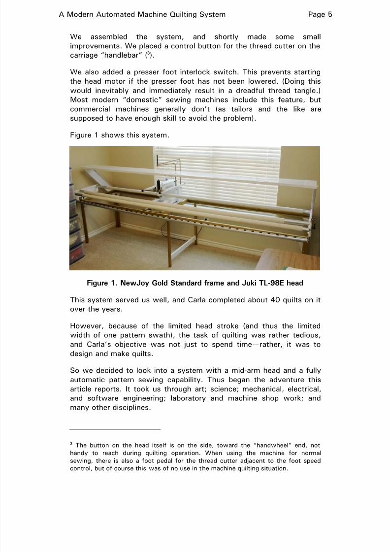
Figure 1 shows this system.
Figure 1. NewJoy Gold Standard frame and Juki TL-98E head
This system served us well, and Carla completed about 40 quilts on it
over the years.
However, because of the limited head stroke (and thus the limited
width of one pattern swath), the task of quilting was rather tedious,
and Carla’s objective was not just to spend time—rather, it was to
design and make quilts.
So we decided to look into a system with a mid-arm head and a fully
automatic pattern sewing capability. Thus began the adventure this
article reports. It took us through art; science; mechanical, electrical,and software engineering; laboratory and machine shop work; and
many other disciplines.
3 The button on the head itself is on the side, toward the “handwheel” end, not
handy to reach during quilting operation. When using the machine for normal
sewing, there is also a foot pedal for the thread cutter adjacent to the foot speed
control, but of course this was of no use in the machine quilting situation.
8/2/2019 DIY Quilting Machine
http://slidepdf.com/reader/full/diy-quilting-machine 6/32
A Modern Automated Machine Quilting System Page 6
THE NEW SYSTEM
Introduction
After considerable research, we decided to assemble a machine
quilting system from these subsystems:
•
Frame. The frame is a Magic frame, made by NewJoy Quilting
Products, Inc. (introduced in 2007). This frame is suitable for work
with heads having throat depths up to perhaps 18”, and can be
assembled to an overall spindle width of 12’. It is of heavy-duty
aluminum construction, and provides for an overhead pattern shelf
(or a “gallery” shelf at table level behind, if that is for some reason
preferred).
• Sewing head. The sewing head is a Crystal Quilter head, made by
NewJoy (introduced in spring of 2008). This head has a throat depth
of 16” and is equipped with an electric thread cutter, an automatic
needle threader (another feature pooh-poohed by old-time quilters,who never had them on their sewing machines either), and a presser
foot interlock. This machine uses the stitching and drive
mechanisms of the Janome 1600P commercial sewing machine,
mounted in a longer housing designed for the purpose.
• Automation system. This is a PC Quilter Model SF computer
controlled quilting system, made by Quilting Technologies of Port
Townsend, Washington. This system comprises a two-axis
servo-driven carriage that replaces the normal carriage on the
machine quilting frame. A controller in the carriage interfaces with a
user-supplied PC, which serves as the processor host, running a
specialized suite of software. We will describe this system in some
detail as we go.
• Host computer. This is a Dell Latitude D600 laptop computer
(1.6 GHz clock speed), with 512 MiB of memory.
To the best of our knowledge, as of this writing (October, 2008) this
is the first mating of the PC Quilter automation system to the NewJoy
Magic frame and the NewJoy Crystal Quilter sewing head.
Adaptation of the PC Quilter automation system
The PC Quilter (PCQ) automation system has evolved over a number
of years, and the product line includes a number of different
arrangements. It is intended that the package be adaptable to a wide
range of quilting machine frames and associated sewing heads.
There are two basic physical configurations. In one (the “basic”
family), the servo-controlled carriage that is the heart of the system
replaces the normal carriage on the machine quilting frame to be used.
8/2/2019 DIY Quilting Machine
http://slidepdf.com/reader/full/diy-quilting-machine 7/32
A Modern Automated Machine Quilting System Page 7
In another (the “side-mount” model), used especially in long-arm
systems, the existing carriage is retained, and the PCQ system works
through an auxiliary servo-controlled carriage mounted alongside the
main carriage and mechanically coupled to it.
The basic PCQ carriage comprises a lower carriage and an upper
carriage. The upper carriage moves in the fore-and-aft direction (the
Y-axis) on ball-bearing steel wheels running on rails on the lower
carriage. It is driven by a stepping motor working through a toothed
belt attached to the upper carriage.
The lower carriage is moved left-to-right (the X-axis) along the rails of
the machine quilting frame, and thus must be adapted to the frame
construction involved. Again, drive in this direction is by way of a
stepping motor, operating on a toothed belt extending the full width of
the frame.
The PCQ carriage “out of the box” has a set of ball-bearing X-axis
wheels at a fixed spacing. In some machine quilting frames, the
left-to-right travel is along simple rails (reminiscent to those on which
a sliding patio door runs) fastened to a tabletop (perhaps a folding
“banquet table”) with clamps (sometimes even carpenter’s clamps—
how agricultural!). In some such cases, the rails can be shifted in their
location until they match the preordained wheel spacing of the stock
PCQ carriage, and that is all there is to it.
More commonly, though, these “default” wheels are removed and the
PCQ carriage fastened to a mechanical adaptation assembly that
carries wheels of appropriate design and spacing running on the tracksof the frame. Many major frame manufacturers offer PCQ adaptation
kits for their frames. NewJoy, for example, offers such a kit for their
Gold Standard frame, and is likely developing one for their new Magic
frame. However, it is not yet available. Accordingly, we designed and
had fabricated an appropriate carriage adaptation assembly (which we
will describe at length shortly).
Sewing head motor control by the PC Quilter system
The PCQ system offers many modes of control of the motor of the
sewing head, as needed to accommodate a range of heads. Thesystem never “dynamically” controls the head speed. It does not, for
example, increase and decrease the head speed during sewing of the
pattern. Rather, the modus operandi depends on moving the carriage
at a constant velocity, so that with the head running at a constant
speed (in terms of number of stitches per second), the stitch length in
the quilting will remain constant.
Nevertheless, in some situations, the way in which the PCQ system
starts the sewing head motor also requires that it control the speed,
8/2/2019 DIY Quilting Machine
http://slidepdf.com/reader/full/diy-quilting-machine 8/32
A Modern Automated Machine Quilting System Page 8
but only in the sense of putting into effect a fixed speed that is
preselected by the user.
One interface offered by the PCQ system for head motor control
(start-stop only) provides a 12 V signal on an interface jack. In one
mode, the signal is on when the motor is to run and off otherwise. In
another mode, a short pulse of the signal is provided when the motor
is to start and another short pulse when it is to stop. It is this
interface in the latter mode that we exploit in our installation.
Carriage stroke, resolution, and speed
The carriage of the PCQ SF system has an overall Y-direction stroke
capability of 15.1”. The usable stroke is of course constrained by head
throat depth considerations. The X-direction stroke is determined by
the width of the frame and the overall carriage dimensions. In our
system, the full X-direction stroke is 106.5”.
The stepping motors use in the PCQ system have 400 full steppositions per revolution, The drive sprockets have a pitch diameter of
1.4324” (a pitch circumference of 4.5000”), and thus the “full step”
resolution of the carriage in each direction is 0.01125”. The control
system allows positioning in terms of half steps, giving an ultimate
incremental resolution of 0.005625”.
The carriage travel speed to be used for a particular task is chosen
from a set of 7 predefined speeds (the specific speed values
associated with each ”step” being defined by a table in the
initialization file). The fastest practical attainable speed is 2.25 in/sec.
Our system is programmed for this as its top available speed.
In practice, considerations of head and carriage dynamics suggest that
a nominal speed of perhaps 1.25 in/sec is about the fastest that
should be used.
In operation, the same speed occurs regardless of the instantaneous
track direction (the velocity vector has a constant magnitude),
resulting in a consistent stitch length (for any given stitching rate by
the head).
PC Quilter flexibility
As a result of its long history of adaptation to many different system
configurations, and for use by artisans with a wide range of needs, the
PCQ system is extraordinarily flexible. Some might call it
“nerd-oriented”, and in fact, when one places an order for the system,
one must undergo a brief computer literacy evaluation by the Quilting
Technologies technical support desk!

8/2/2019 DIY Quilting Machine
http://slidepdf.com/reader/full/diy-quilting-machine 9/32
A Modern Automated Machine Quilting System Page 9
Many system parameters are set by entries in an initialization file, and
all are discussed in considerable detail in the system documentation.
PC QUILTER OPERATION
PC Quilter user interface
In its earliest manifestation (2001), although the PC Quilter softwareoperated under Windows, it was operated by the user from the host
computer via a DOS-like character-mode serial interactive dialog
(sometimes called a “console interface”, by reference to early
computer consoles, in which the operator interacted via a keyboard
and a printer). This is described in the PCQ literature as the “command
line interface” (CLI) form of control. That term is, however,
inappropriate for this mode.4
The motivation for this (in 2001) seemingly-primitive user interface
was to permit operation on PCs of very limited processor capacity—
which could be acquired, used, at low cost during that time period.
In 2004, Quilting Technologies introduced a graphic user interface
(GUI) “front end” for the system. This has a bona fide Windows user
interface, and behind the scene feeds instructions to the underlying
PCQ operating program. (Its top-level portion is called QTMenu.)
In 2007, Quilting Technologies introduced a color touchscreen control
panel for the system. It can be, for example, mounted on the sewing
head. It operates with its own “front end” software, and, like the
graphic user interface package, feeds commands behind the scene to
the underlying PCQ program.
There are, however, some subtleties of pattern modification and
manipulation that cannot readily be done from the touchscreen (in its
present version), so even if it is installed, some preparatory work may
need to be done at the computer.
The PC Quilter pattern language
Pattern files for use by the PCQ system are ASCII files using a very
straightforward syntax. The principal statement describes a point on
4 “Command line interface” implies a non-interactive mode of control of a program,
in which any instructions, option settings, values, identification of files to be
processed, and so forth as given as “parameters” to the command statement,
submitted to the “DOS prompt”, that loads and starts the program. The PCQ
software is not used in that mode. The user starts it (in Windows, with a shortcut)
and all other input is provided interactively in response to prompts given in a
“DOS-looking” serial, character-oriented dialog. This is not a “command line
interface”.
8/2/2019 DIY Quilting Machine
http://slidepdf.com/reader/full/diy-quilting-machine 10/32
A Modern Automated Machine Quilting System Page 10
the pattern path in terms of X and Y coordinates, expressed in signed
decimal notation to a precision of up to 3 decimal places. The values
are placed in the order X, Y, with just a space between them.
For basic operation, the origin (0, 0) is arbitrary. The first point is
always executed at the physical location of the carriage when
execution begins, and all other points are placed relative to the
coordinates of that initial point.
The PCQ pattern language is described in considerable detail in
Appendix A.
SYSTEM PLAN AND ADAPTATION
Carriage mechanical adaptation
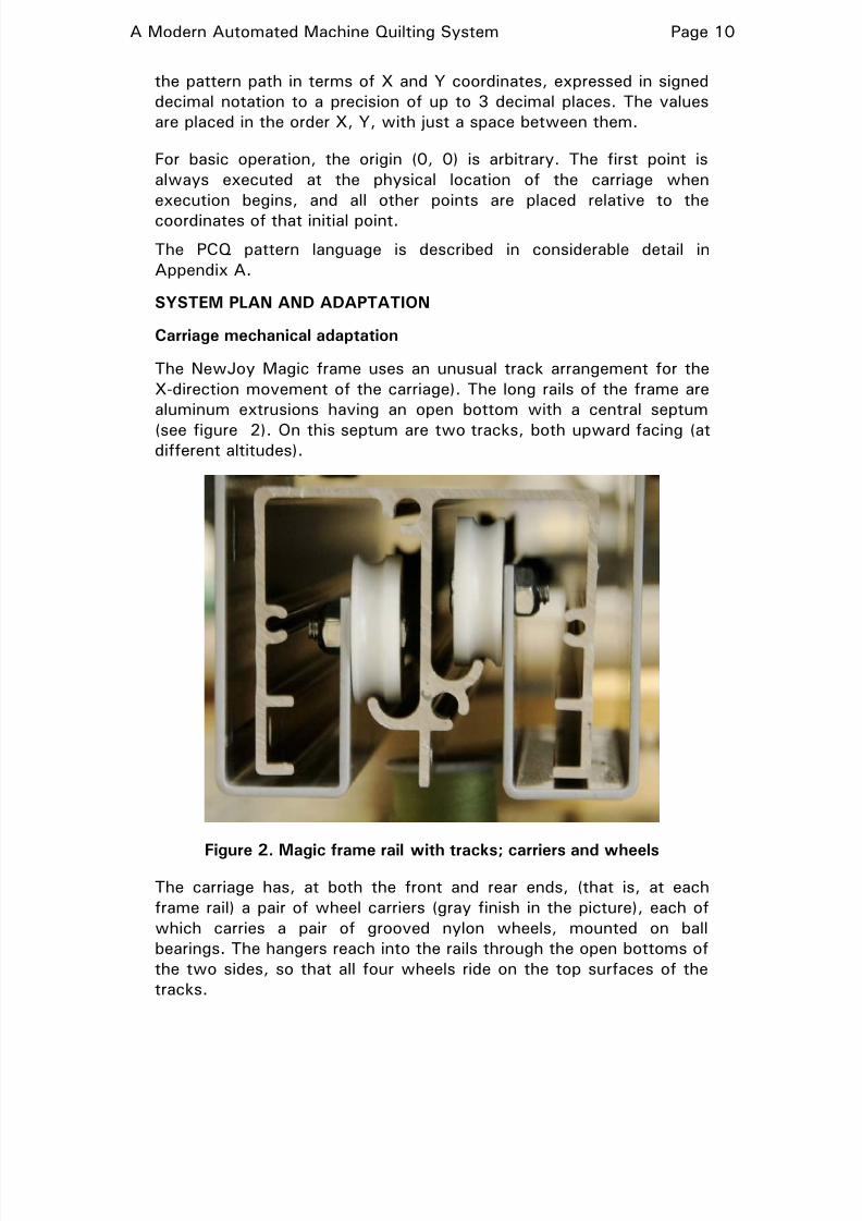
The NewJoy Magic frame uses an unusual track arrangement for the
X-direction movement of the carriage). The long rails of the frame are
aluminum extrusions having an open bottom with a central septum
(see figure 2). On this septum are two tracks, both upward facing (atdifferent altitudes).
Figure 2. Magic frame rail with tracks; carriers and wheels
The carriage has, at both the front and rear ends, (that is, at each
frame rail) a pair of wheel carriers (gray finish in the picture), each of
which carries a pair of grooved nylon wheels, mounted on ball
bearings. The hangers reach into the rails through the open bottoms of
the two sides, so that all four wheels ride on the top surfaces of the
tracks.

8/2/2019 DIY Quilting Machine
http://slidepdf.com/reader/full/diy-quilting-machine 11/32
A Modern Automated Machine Quilting System Page 11
After some study, we concluded that the best approach to adaptation
would be to mount the two pairs of standard wheel hangers on the
ends of an adapter plate with a dropped center. The PCQ carriage
would then sit into that dropped center (resting essentially on the
edges of the two flanges on the carriage which in the “default”
configuration of the carriage carry its X-direction wheels).
A related design issue was the positioning of the PCQ carriage along
the length of the adapter plate. This had to be resolved with reference
to the issue of matching:
• The possible Y-direction travel of the head on the PCQ carriage (as
limited by the upper carriage wheel and drive arrangements), and
• The possible Y-direction travel of the head considering the location
of the takeup spindle (the travel is limited where the throat rear, or
the needle bar at the front, would strike the loaded takeup roller).
We wanted to have the excess of the former travel over the latter
approximately equally divided between the two ends of travel.
Attaining this required the PCQ carriage to be located on the adapter
plate in such a location that there would be interference between the
rearmost extensions of the PCQ carriage side frame and the actual
frame rails. Fortunately, there was nothing (much) to prevent notching
the carriage side frame to get the necessary clearance.
There was some question as to how the adapter plate should be given
the necessary flexural stiffness. A design with side flanges would
have been ideal, but would have been costly to fabricate on a
“one-off” basis. Instead, we chose to have the plate made of relatively
large-gauge steel plate (10 gauge, nominally 0.1345” thick), and then
to augment its stiffness over its long central span with aluminum
angle ribs underneath.
After the design was completed, a local machine shop made the plate
itself for us quickly, shearing the material with a really big shear
(“well, it’s not as big as it seems—the blade has a nick in it about two
feet from the right end”) and forming it with a really big press brake.
We then drilled all the necessary holes, added the stiffeners, madesome mounting brackets to hold the PCQ carriage in place, notched
the carriage as discussed above, and put the whole works together.
Sounds really simple, doesn’t it!
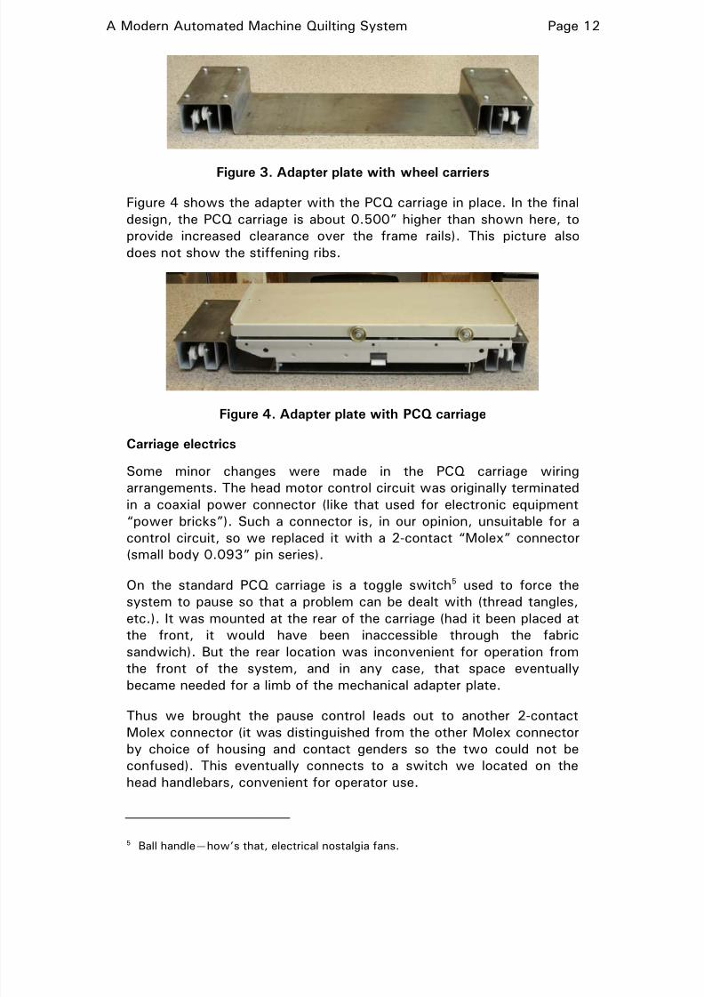
Figure 3 shows the adapter plate itself, with the original wheel carriers
attached. (The stiffening ribs are not in place here).
8/2/2019 DIY Quilting Machine
http://slidepdf.com/reader/full/diy-quilting-machine 12/32
A Modern Automated Machine Quilting System Page 12
Figure 3. Adapter plate with wheel carriers
Figure 4 shows the adapter with the PCQ carriage in place. In the final
design, the PCQ carriage is about 0.500” higher than shown here, to
provide increased clearance over the frame rails). This picture also
does not show the stiffening ribs.
Figure 4. Adapter plate with PCQ carriage
Carriage electrics
Some minor changes were made in the PCQ carriage wiring
arrangements. The head motor control circuit was originally terminated
in a coaxial power connector (like that used for electronic equipment
“power bricks”). Such a connector is, in our opinion, unsuitable for acontrol circuit, so we replaced it with a 2-contact “Molex” connector
(small body 0.093” pin series).
On the standard PCQ carriage is a toggle switch5 used to force the
system to pause so that a problem can be dealt with (thread tangles,
etc.). It was mounted at the rear of the carriage (had it been placed at
the front, it would have been inaccessible through the fabric
sandwich). But the rear location was inconvenient for operation from
the front of the system, and in any case, that space eventually
became needed for a limb of the mechanical adapter plate.
Thus we brought the pause control leads out to another 2-contact
Molex connector (it was distinguished from the other Molex connector
by choice of housing and contact genders so the two could not be
confused). This eventually connects to a switch we located on the
head handlebars, convenient for operator use.
5 Ball handle—how’s that, electrical nostalgia fans.
8/2/2019 DIY Quilting Machine
http://slidepdf.com/reader/full/diy-quilting-machine 13/32
A Modern Automated Machine Quilting System Page 13
We also removed an electromechanical module in the carriage used for
motor control in other application configurations6 and installed in its
place the power unit for the carriage (which would otherwise have just
hung around outside the carriage someplace).
The original design of the PCQ system used a parallel port to connect
to the host PC. Later, a serial port option was added. Today, the
preferred mode of interface is via a USB port on the host (operating in
a COM port emulation mode). The standard configuration is to run a
serial cable to the host computer and there insinuate a USB-to-COM
adapter supplied with the system.
Since we were trying to minimize the umbilical load on the carriage,
we emplaced the USB-to-COM adapter directly into the COM port on
the carriage controller board, and ran a USB cable all the way to the
host PC. (A second USB cable runs from the touchscreen control
panel, mounted on the sewing head, to the host PC.)
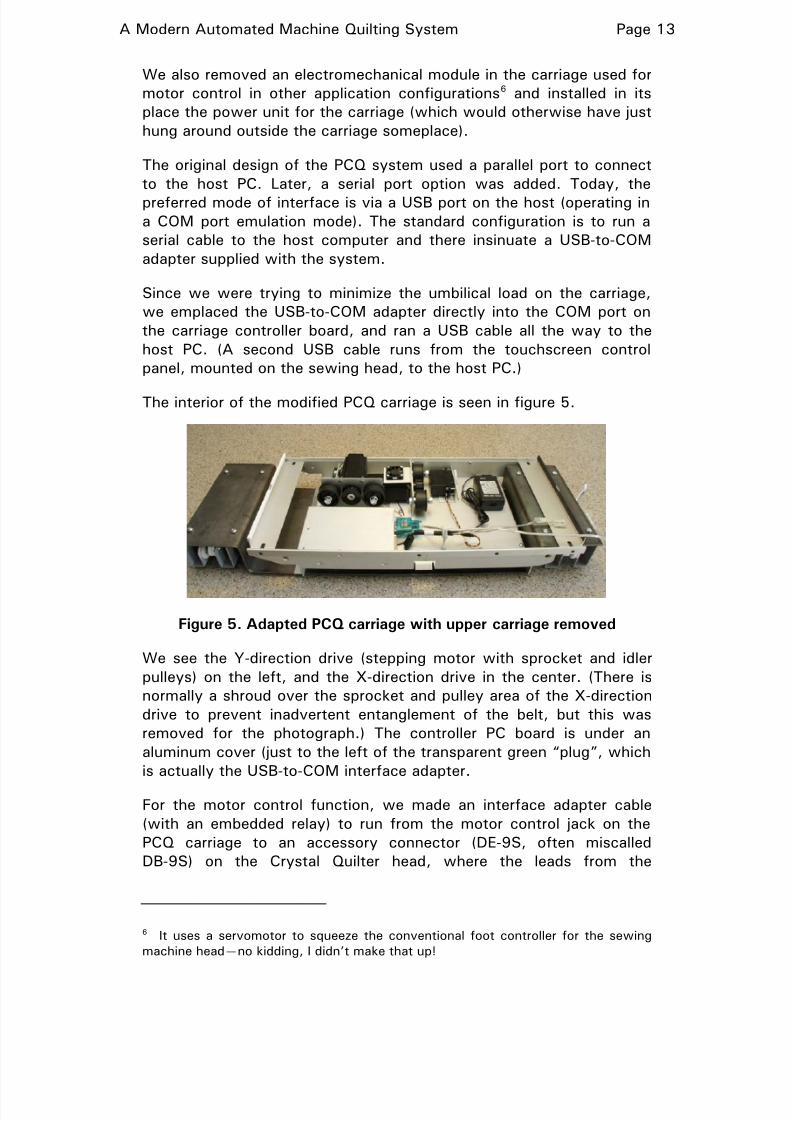
The interior of the modified PCQ carriage is seen in figure 5.
Figure 5. Adapted PCQ carriage with upper carriage removed
We see the Y-direction drive (stepping motor with sprocket and idler
pulleys) on the left, and the X-direction drive in the center. (There is
normally a shroud over the sprocket and pulley area of the X-direction
drive to prevent inadvertent entanglement of the belt, but this was
removed for the photograph.) The controller PC board is under an
aluminum cover (just to the left of the transparent green “plug”, which
is actually the USB-to-COM interface adapter.
For the motor control function, we made an interface adapter cable
(with an embedded relay) to run from the motor control jack on the
PCQ carriage to an accessory connector (DE-9S, often miscalled
DB-9S) on the Crystal Quilter head, where the leads from the
6 It uses a servomotor to squeeze the conventional foot controller for the sewing
machine head—no kidding, I didn’t make that up!
8/2/2019 DIY Quilting Machine
http://slidepdf.com/reader/full/diy-quilting-machine 14/32
A Modern Automated Machine Quilting System Page 14
momentary start-stop button on the handlebars were accessible. The
relay, a subminiature type, was placed in the hood of the mating
DE-9P plug so no inline pod was required.
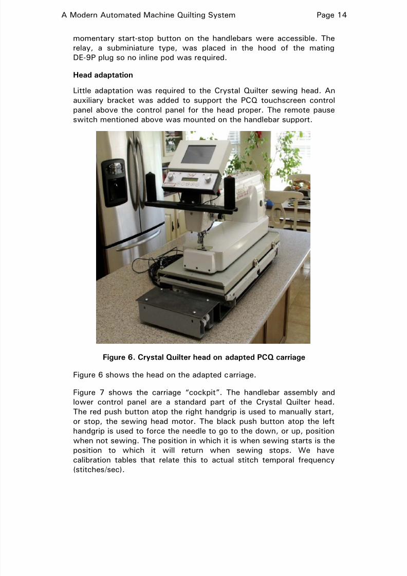
Head adaptation
Little adaptation was required to the Crystal Quilter sewing head. An
auxiliary bracket was added to support the PCQ touchscreen controlpanel above the control panel for the head proper. The remote pause
switch mentioned above was mounted on the handlebar support.
Figure 6. Crystal Quilter head on adapted PCQ carriage
Figure 6 shows the head on the adapted carriage.
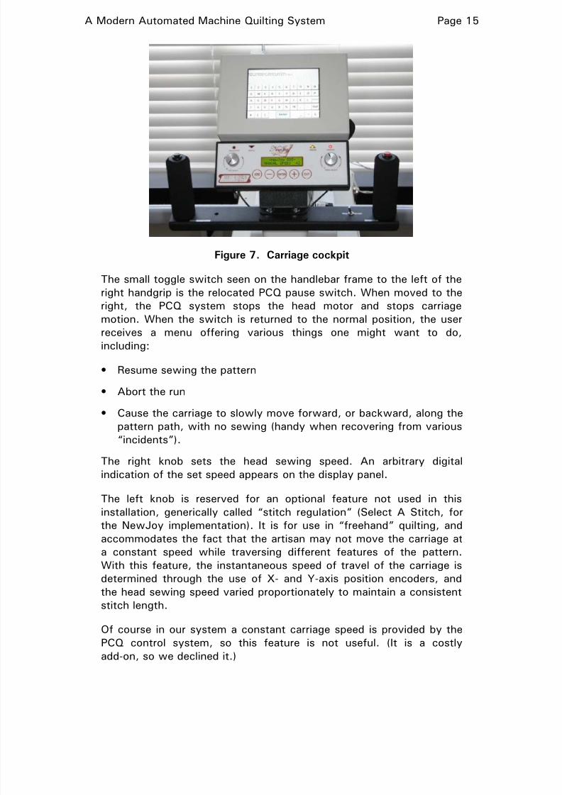
Figure 7 shows the carriage “cockpit”. The handlebar assembly and
lower control panel are a standard part of the Crystal Quilter head.The red push button atop the right handgrip is used to manually start,
or stop, the sewing head motor. The black push button atop the left
handgrip is used to force the needle to go to the down, or up, position
when not sewing. The position in which it is when sewing starts is the
position to which it will return when sewing stops. We have
calibration tables that relate this to actual stitch temporal frequency
(stitches/sec).
8/2/2019 DIY Quilting Machine
http://slidepdf.com/reader/full/diy-quilting-machine 15/32
A Modern Automated Machine Quilting System Page 15
Figure 7. Carriage cockpit
The small toggle switch seen on the handlebar frame to the left of theright handgrip is the relocated PCQ pause switch. When moved to the
right, the PCQ system stops the head motor and stops carriage
motion. When the switch is returned to the normal position, the user
receives a menu offering various things one might want to do,
including:
• Resume sewing the pattern
• Abort the run
• Cause the carriage to slowly move forward, or backward, along thepattern path, with no sewing (handy when recovering from various
“incidents”).
The right knob sets the head sewing speed. An arbitrary digital
indication of the set speed appears on the display panel.
The left knob is reserved for an optional feature not used in this
installation, generically called “stitch regulation” (Select A Stitch, for
the NewJoy implementation). It is for use in “freehand” quilting, and
accommodates the fact that the artisan may not move the carriage at
a constant speed while traversing different features of the pattern.With this feature, the instantaneous speed of travel of the carriage is
determined through the use of X- and Y-axis position encoders, and
the head sewing speed varied proportionately to maintain a consistent
stitch length.
Of course in our system a constant carriage speed is provided by the
PCQ control system, so this feature is not useful. (It is a costly
add-on, so we declined it.)

8/2/2019 DIY Quilting Machine
http://slidepdf.com/reader/full/diy-quilting-machine 16/32
A Modern Automated Machine Quilting System Page 16
The upper unit is the touchscreen control panel for the PCQ system
(also a costly add-on). Shown is an alphanumeric entry screen, in this
case used to select the pattern file to be used. One can enter a partial
name and touch Enter, in which case a screened file list comes up,
from which the desired file can be selected by touching a very tiny
button at the left of the filename (hard against the panel bezel
opening—one had best have long fingernails to do this).
THE COMPLETE ASSEMBLY
Overview
Figure 8 shows about the left half of the complete system.
Figure 8. Completed system
Its overall width is 127” wide (including allowance for protruding
mechanical controls) and 43” deep. A clearance of 4” is required at
the rear to accommodate protrusion of the carriage and head at the
limit of practical rearward travel. The spindles are 120” long. A
pattern up to about 100” wide, on fabric up to about 104” wide, can
be worked. (The actual frame “kit” can be used to assemble a frame
24” wider.)
The X-direction toothed belt
In figure 8, we saw the X-axis toothed belt, which engages a sprocket
on the X-axis stepping motor (with two idler pulleys to provide good
contact). The belt is attached to the two end frame boxes of the
frame via square U-bolts. These are held with prevailing
vibration-resisting nuts, allowing adjustment of the belt tension. The
arrangement is shown in detail in figure 9.
The belt is bent back over the U-bolt so that the teeth on the facing
sides interlock, providing a strong, stable loop. The loop is held closed
8/2/2019 DIY Quilting Machine
http://slidepdf.com/reader/full/diy-quilting-machine 17/32
A Modern Automated Machine Quilting System Page 17
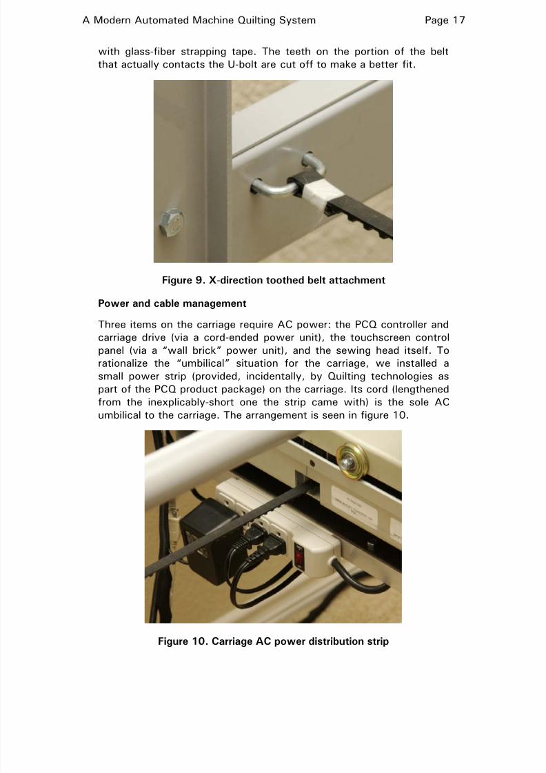
with glass-fiber strapping tape. The teeth on the portion of the belt
that actually contacts the U-bolt are cut off to make a better fit.
Figure 9. X-direction toothed belt attachment
Power and cable management
Three items on the carriage require AC power: the PCQ controller and
carriage drive (via a cord-ended power unit), the touchscreen control
panel (via a “wall brick” power unit), and the sewing head itself. To
rationalize the “umbilical” situation for the carriage, we installed a
small power strip (provided, incidentally, by Quilting technologies as
part of the PCQ product package) on the carriage. Its cord (lengthened
from the inexplicably-short one the strip came with) is the sole ACumbilical to the carriage. The arrangement is seen in figure 10.
Figure 10. Carriage AC power distribution strip
8/2/2019 DIY Quilting Machine
http://slidepdf.com/reader/full/diy-quilting-machine 18/32
A Modern Automated Machine Quilting System Page 18
The touchscreen panel came from the factory with a single very long
umbilical, a single sheath of a very nice springy fabric loom through
which ran both a long DC power cable (to its wall brick) and a USB
cable (to go to the host computer.)
In our case, the power brick plugs into the power strip on the carriage,
so the DC cable was stripped out of the loom sheath. We used the
freed space in the sheath to carry the USB cable from the PCB
controller. Thus we now have only two umbilicals to the carriage, a
single AC power cord, and the dual USB cable.
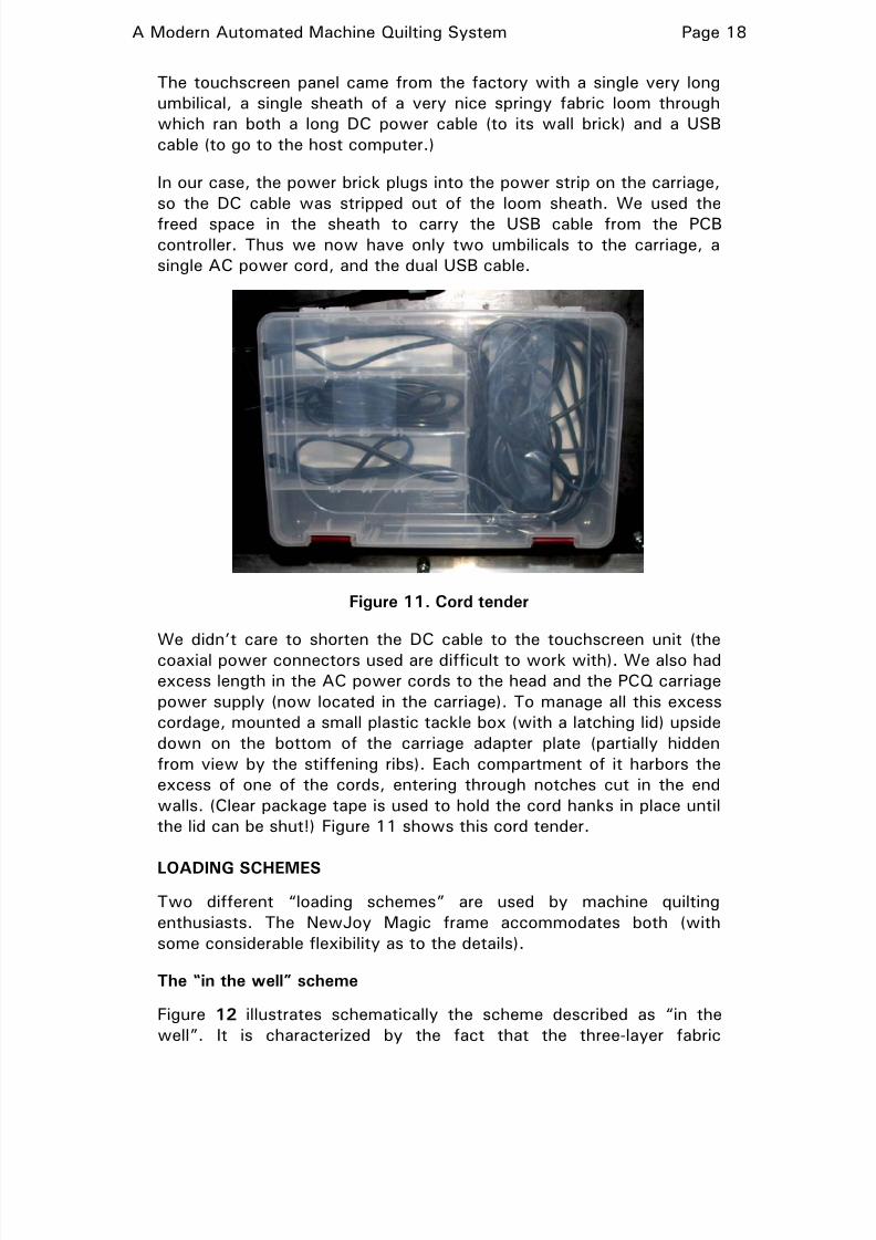
Figure 11. Cord tender
We didn’t care to shorten the DC cable to the touchscreen unit (the
coaxial power connectors used are difficult to work with). We also had
excess length in the AC power cords to the head and the PCQ carriage
power supply (now located in the carriage). To manage all this excess
cordage, mounted a small plastic tackle box (with a latching lid) upside
down on the bottom of the carriage adapter plate (partially hidden
from view by the stiffening ribs). Each compartment of it harbors the
excess of one of the cords, entering through notches cut in the end
walls. (Clear package tape is used to hold the cord hanks in place until
the lid can be shut!) Figure 11 shows this cord tender.
LOADING SCHEMES
Two different “loading schemes” are used by machine quilting
enthusiasts. The NewJoy Magic frame accommodates both (with
some considerable flexibility as to the details).
The “in the well” scheme
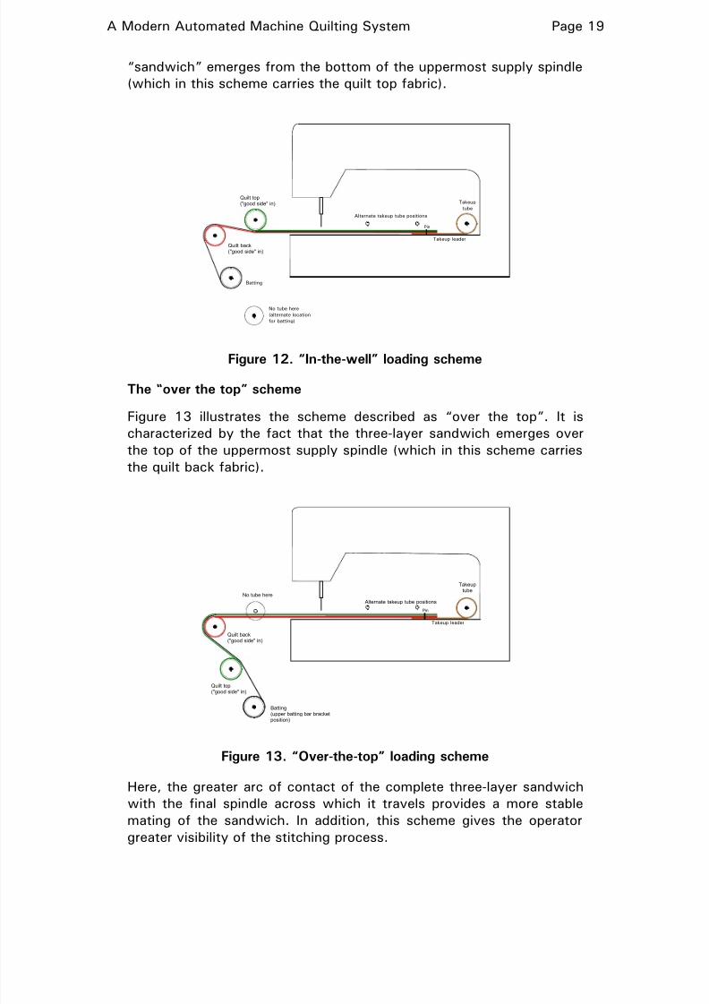
Figure 12 illustrates schematically the scheme described as “in the
well”. It is characterized by the fact that the three-layer fabric
8/2/2019 DIY Quilting Machine
http://slidepdf.com/reader/full/diy-quilting-machine 19/32
A Modern Automated Machine Quilting System Page 19
“sandwich” emerges from the bottom of the uppermost supply spindle
(which in this scheme carries the quilt top fabric).
Alternate takeup tube positions
Takeup
tube
Batting
No tube here
(alternate location
for batting)
Takeup leader
Pin
Quilt back("good side" in)
Quilt top("good side" in)
Figure 12. “In-the-well” loading scheme
The “over the top” scheme
Figure 13 illustrates the scheme described as “over the top”. It is
characterized by the fact that the three-layer sandwich emerges over
the top of the uppermost supply spindle (which in this scheme carries
the quilt back fabric).
Alternate takeup tube positions
Takeuptube
No tube here
Quilt back("good side" in)
Quilt top("good side" in)
Batting(upper batting bar bracketposition)
Takeup leader
Pin
Figure 13. “Over-the-top” loading scheme
Here, the greater arc of contact of the complete three-layer sandwich
with the final spindle across which it travels provides a more stable
mating of the sandwich. In addition, this scheme gives the operator
greater visibility of the stitching process.
8/2/2019 DIY Quilting Machine
http://slidepdf.com/reader/full/diy-quilting-machine 20/32
A Modern Automated Machine Quilting System Page 20
This scheme does require more overall depth of the machine frame. (It
is not really practical, for example, on the NewJoy Gold Standard
frame we previously used.)
Batting options
Under either threading scheme, there are several options for the
placement of the batting supply:
• It can be wound onto a supply spindle carried on the frame near
the spindles for the top and back.
• A “mill roll” of batting (on a fiber core) can be placed on a spindle
(just used as an axle) mounted near the bottom of the frame.
• It can be piled on the floor beneath the frame (or on a shelf
installed there).
THE PINNING SHELF
The top and back fabric panels are attached to their respective supply
spindles by being pinned to short muslin leaders, which are in turn
attached to the spindles themselves with Velcro. Similarly, the leading
edge of the completed “sandwich” is attached to the takeup spindle
by being pinned to a short muslin leader there.
Sometimes, the supply spindles are “loaded” with their fabric panels
on a floor (we call it “loft loading”). In that situation, it is easy to pin
the fabric to the leader, since both lie nicely on the floor. But in many
cases it is more practical to wind the fabric onto the spindles withthem in place on the machine. For one thing, on the new machine, the
spindles are very heavy, and as well are 10’ long, so maneuvering
them between the “loft” and the “studio” is not that easy. Now,
pinning the fabric panel to the edge of the leader is not so simple.
In any case, the three-layer sandwich must be pinned to the takeup
leader in situ, which turns out to be very tricky done “in midair”.
In order to facilitate these operations, we have equipped the new
system with a pinning shelf system of our design. This temporarily
holds a narrow board of soft wood (the “pinning shelf”) in place as awork surface for performing each of the three pinning operations.
Two wooden supports, which are placed on the forward frame rails
near the ends of the machine, support the shelf at each of the
positions where it is required. (There are actually four positions that
must be accommodated, to cater for two different “threading
schemes” that can be used with the machine.)
8/2/2019 DIY Quilting Machine
http://slidepdf.com/reader/full/diy-quilting-machine 21/32
A Modern Automated Machine Quilting System Page 21
In the illustrations below, the system is configured for “over-the-top”
loading.
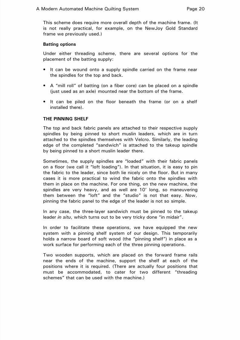
In figure 14 we see one of the shelf supports. The surfaces that
contact the frame rail have felt pads to avoid marring of the anodized
rail surfaces.
Figure 14. Pinning shelf support
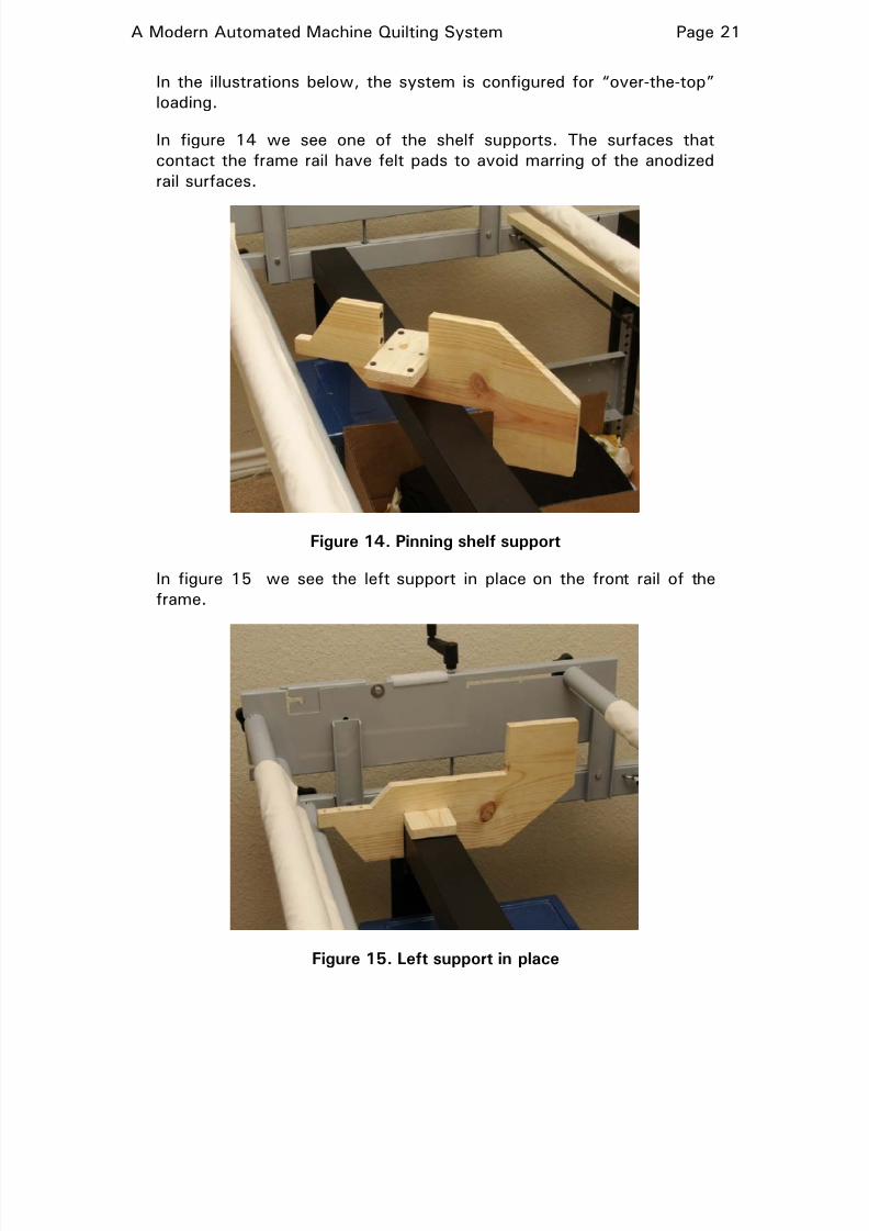
In figure 15 we see the left support in place on the front rail of the
frame.
Figure 15. Left support in place
8/2/2019 DIY Quilting Machine
http://slidepdf.com/reader/full/diy-quilting-machine 22/32
A Modern Automated Machine Quilting System Page 22
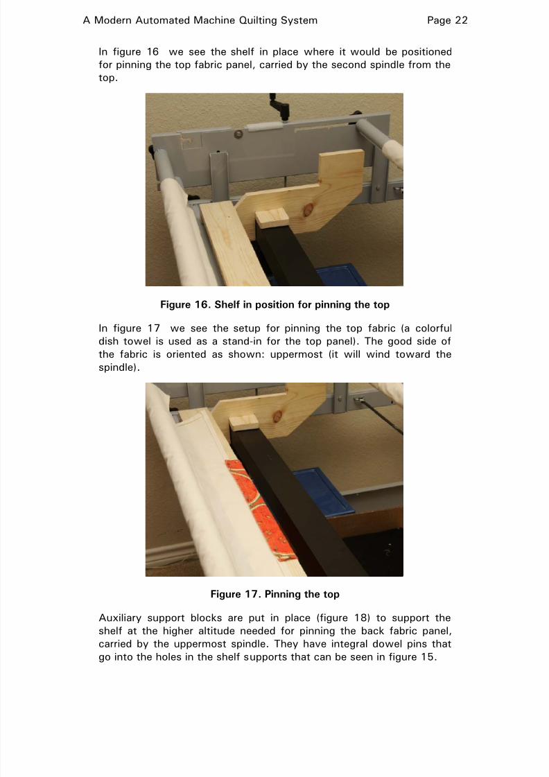
In figure 16 we see the shelf in place where it would be positioned
for pinning the top fabric panel, carried by the second spindle from the
top.
Figure 16. Shelf in position for pinning the top
In figure 17 we see the setup for pinning the top fabric (a colorful
dish towel is used as a stand-in for the top panel). The good side of
the fabric is oriented as shown: uppermost (it will wind toward the
spindle).
Figure 17. Pinning the top
Auxiliary support blocks are put in place (figure 18) to support the
shelf at the higher altitude needed for pinning the back fabric panel,
carried by the uppermost spindle. They have integral dowel pins that
go into the holes in the shelf supports that can be seen in figure 15.
8/2/2019 DIY Quilting Machine
http://slidepdf.com/reader/full/diy-quilting-machine 23/32
A Modern Automated Machine Quilting System Page 23
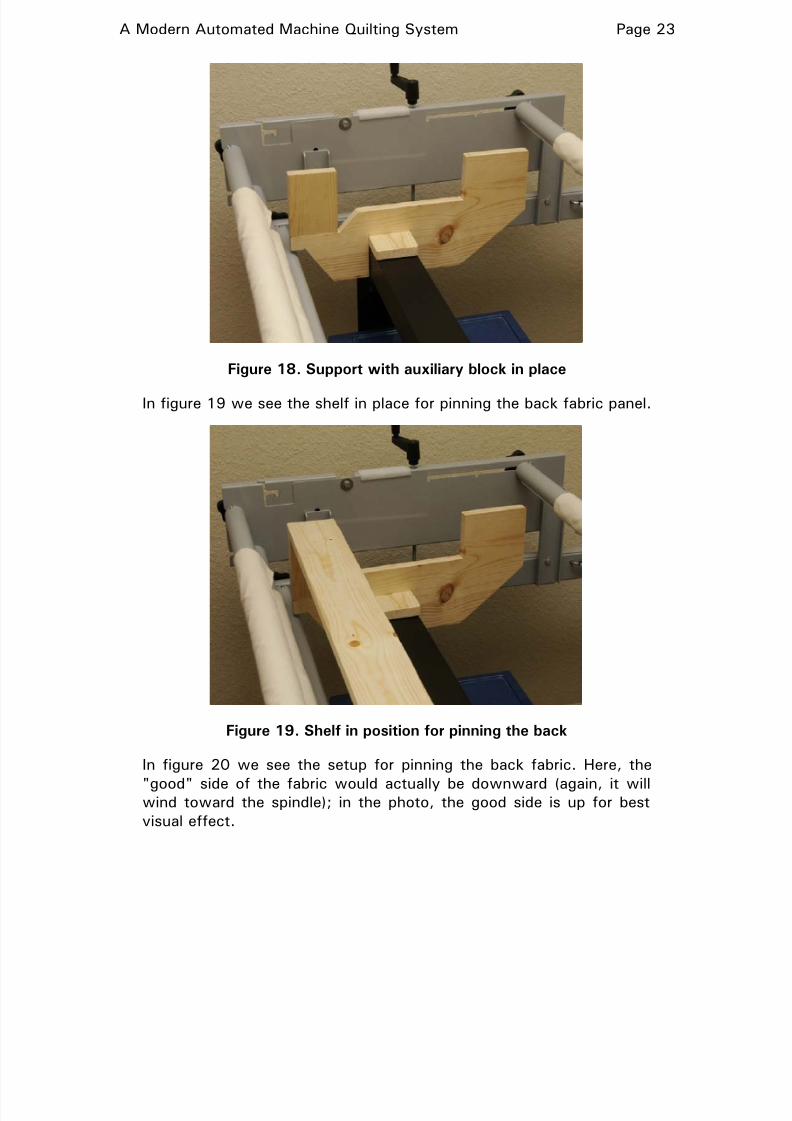
Figure 18. Support with auxiliary block in place
In figure 19 we see the shelf in place for pinning the back fabric panel.
Figure 19. Shelf in position for pinning the back
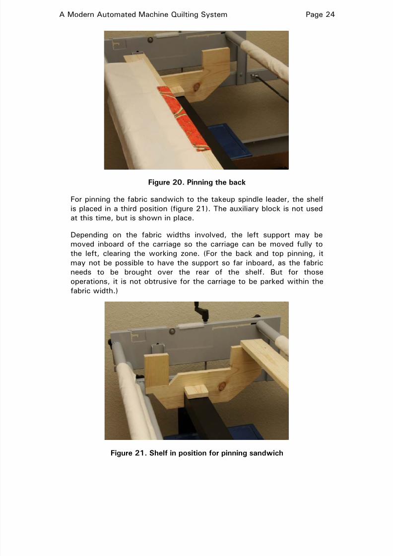
In figure 20 we see the setup for pinning the back fabric. Here, the
"good" side of the fabric would actually be downward (again, it willwind toward the spindle); in the photo, the good side is up for best
visual effect.
8/2/2019 DIY Quilting Machine
http://slidepdf.com/reader/full/diy-quilting-machine 24/32
A Modern Automated Machine Quilting System Page 24
Figure 20. Pinning the back
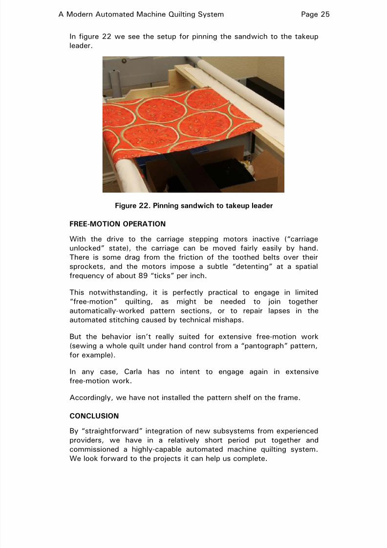
For pinning the fabric sandwich to the takeup spindle leader, the shelf
is placed in a third position (figure 21). The auxiliary block is not used
at this time, but is shown in place.
Depending on the fabric widths involved, the left support may be
moved inboard of the carriage so the carriage can be moved fully to
the left, clearing the working zone. (For the back and top pinning, it
may not be possible to have the support so far inboard, as the fabric
needs to be brought over the rear of the shelf. But for those
operations, it is not obtrusive for the carriage to be parked within the
fabric width.)
Figure 21. Shelf in position for pinning sandwich
8/2/2019 DIY Quilting Machine
http://slidepdf.com/reader/full/diy-quilting-machine 25/32
A Modern Automated Machine Quilting System Page 25
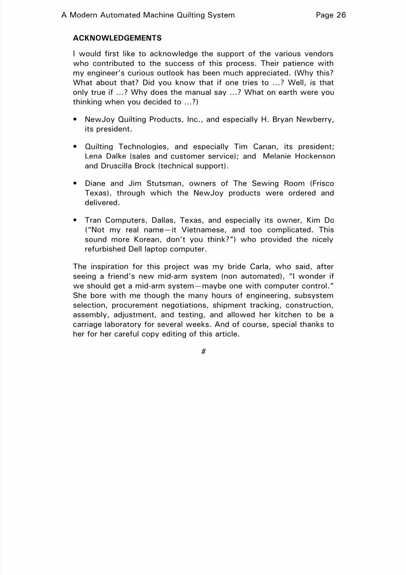
In figure 22 we see the setup for pinning the sandwich to the takeup
leader.
Figure 22. Pinning sandwich to takeup leader
FREE-MOTION OPERATION
With the drive to the carriage stepping motors inactive (“carriage
unlocked” state), the carriage can be moved fairly easily by hand.
There is some drag from the friction of the toothed belts over their
sprockets, and the motors impose a subtle “detenting” at a spatial
frequency of about 89 “ticks” per inch.
This notwithstanding, it is perfectly practical to engage in limited
“free-motion” quilting, as might be needed to join together
automatically-worked pattern sections, or to repair lapses in the
automated stitching caused by technical mishaps.
But the behavior isn’t really suited for extensive free-motion work
(sewing a whole quilt under hand control from a “pantograph” pattern,
for example).
In any case, Carla has no intent to engage again in extensive
free-motion work.
Accordingly, we have not installed the pattern shelf on the frame.
CONCLUSION
By “straightforward” integration of new subsystems from experienced
providers, we have in a relatively short period put together and
commissioned a highly-capable automated machine quilting system.
We look forward to the projects it can help us complete.
8/2/2019 DIY Quilting Machine
http://slidepdf.com/reader/full/diy-quilting-machine 26/32
A Modern Automated Machine Quilting System Page 26
ACKNOWLEDGEMENTS
I would first like to acknowledge the support of the various vendors
who contributed to the success of this process. Their patience with
my engineer’s curious outlook has been much appreciated. (Why this?
What about that? Did you know that if one tries to …? Well, is that
only true if …? Why does the manual say …? What on earth were you
thinking when you decided to …?)
• NewJoy Quilting Products, Inc., and especially H. Bryan Newberry,
its president.
• Quilting Technologies, and especially Tim Canan, its president;
Lena Dalke (sales and customer service); and Melanie Hockenson
and Druscilla Brock (technical support).
• Diane and Jim Stutsman, owners of The Sewing Room (Frisco
Texas), through which the NewJoy products were ordered and
delivered.
• Tran Computers, Dallas, Texas, and especially its owner, Kim Do
(“Not my real name—it Vietnamese, and too complicated. This
sound more Korean, don’t you think?”) who provided the nicely
refurbished Dell laptop computer.
The inspiration for this project was my bride Carla, who said, after
seeing a friend’s new mid-arm system (non automated), “I wonder if
we should get a mid-arm system—maybe one with computer control.”
She bore with me though the many hours of engineering, subsystem
selection, procurement negotiations, shipment tracking, construction,
assembly, adjustment, and testing, and allowed her kitchen to be a
carriage laboratory for several weeks. And of course, special thanks to
her for her careful copy editing of this article.
#
8/2/2019 DIY Quilting Machine
http://slidepdf.com/reader/full/diy-quilting-machine 27/32
A Modern Automated Machine Quilting System Page 27
APPENDIX A
PCQ Pattern Files
The pattern file
The patterns to be worked through the PCQ system are described in
pattern files. They describe the “path” of the figure in terms of
discrete points. The PCQ software reads this path description and fits
a curve to it, and then gives incremental instructions to the carriage
stepping motors to follow that curve with a resolution of about 0.01”
(about 0.005” in one mode).
Basic syntax
Pattern files for use by the PCQ system are ASCII files using a very
straightforward syntax. The principal statement describes a point on
the pattern path in terms of X and Y coordinates, expressed in signed
decimal notation to a precision of up to 3 decimal places. The values
are placed in the order X, Y, with just a space between them.
For basic operation, the origin (0,0) is arbitrary. The first point is
always executed at the physical location of the carriage when
execution begins, and all other points are placed relative to the
coordinates of that initial point.
Thus this file (shown in its entirety) would result in the system sewing
a 5” x 5” square (in a counterclockwise direction beginning at its near
left corner):
0 0
0 5
5 5
5 0
0 0
The lower left corner of the square (represented by the first point
entry) would be located at the initial carriage position.
Because of the relative nature of the coordinate system, the following
file would generate the same stitched pattern in the same place
(assuming identical initial carriage locations):
1 3
1 8
6 8
6 3
1 3
8/2/2019 DIY Quilting Machine
http://slidepdf.com/reader/full/diy-quilting-machine 28/32
A Modern Automated Machine Quilting System Page 28
However, there is a potential significance to the difference between
the two, because when the basic pattern is modified under control of
specialized commands placed in the pattern file, or entered by the user
on the “control panel” in preparation for execution, certain
transformations are made with respect to the origin (0,0), and hence
their impact varies with the location of the origin with respect to the
pattern figure.
Discontinuous patterns
In some cases, it is not appropriate or practical to have continuous
stitching for the entire pattern. In that case, an interruption to
movement of the head along the path can be made, allowing the user
to cut the thread (hopefully, by just punching a button!) and then
having the system automatically move the carriage to the proper place
to resume stitching. Locations where this should occur are signalized
with the Jump command in the file.
For example, this file would sew two concentric squares:
-2 -2
2 -2
2 2
-2 2
-2 -2
jump
-1.25 -1.25
1.25 -1.25
1.25 1.25
-1.25 1.25
-1.25 -1.25
Here, for symmetry, I arbitrarily use the center of the two squares as
the numerical origin (0, 0). Nevertheless, as always, the first point
(whose coordinates will be considered to be -2, -2) will still be at the
initial physical position of the carriage.
Controlling the initial position relative to a benchmark
We may want to locate each “pass” with respect to some point on the
previous pass, or to some feature on the quilt top, such as a boundary
between blocks. We can easily do that by means of an “initial jump”
(called, for historical reasons, a “courtesy jump” in the PCQ literature).
Suppose we wanted the “single 5”x5” square” pattern we saw earlier
to be executed such that the lower left corner of the pattern (the first
point of the pattern) fell exactly 6 inches below the corresponding
corner of the pattern just sewn. Then we would use this file:
8/2/2019 DIY Quilting Machine
http://slidepdf.com/reader/full/diy-quilting-machine 29/32
A Modern Automated Machine Quilting System Page 29
0 6
jump
0 0
0 5
5 5
5 0
0 0
We would place the sewing point (needle cursor) on the lower left
corner of the previous pattern and execute the file. The first statement
in effect defines that initial physical location of the carriage as having
coordinates 0, 6. However, the jump command immediately following
tells the system to not start sewing at that point but rather to move to
coordinates 0, 0 (in our example, the desired location for the lower left
corner of this “pass”)—6 inches below the initial point.
The head would then be started and the carriage would commence its
movement over the pattern.
Pattern modification
The PCQ system allows the user to start with a pattern defined by a
file and make many kinds of modifications or adaptations to it. These
include:
• Scaling it in the X- and or Y- directions.
• Replicating the pattern in the X- or Y- direction (but not both). Forreplication in the X-direction, a controllable blank space can be
included between the instances.
• Rotating the pattern through an arbitrary angle. [Note 1]
• “Flipping” the pattern about the X- or Y- axis or both. [Note 1]
• Adding “mirrored” instances of the pattern about either axis (or
both). [Note 1]
• Making multiple “radial” instances of the pattern (e.g., turning a
“petal” into a “flower”). [Note 1]
• Offsetting the pattern along the X-axis (essentially, starting at some
point along its width, and adding the omitted portion back in at the
far end). [Note 2]
• Skewing the pattern by shifting the right and/or left sides of its
bounding box up or down, or shifting its top and/or bottom edges to
the right or the left, or both.
8/2/2019 DIY Quilting Machine
http://slidepdf.com/reader/full/diy-quilting-machine 30/32
A Modern Automated Machine Quilting System Page 30
• Trimming a defined portion off the top, bottom, left, or right edge of
the pattern. [Note 2]
Note 1: These operations require that the origin of the pattern
coordinate system be appropriately located with respect to the
figure.
Note 2: These operations will usually result in a bunch of“loose ends” of the pattern line at the new boundary; the
program will connect these together in the best way possible
to allow the pattern to be stitched on a “continuous line”
basis.
These modifications can embedded as commands in the pattern file
itself (so that they will be applied whenever that file is loaded), or they
can be entered during a session by the user “on the control panel”, in
which case they will be applied “on the fly” during the session. In the
latter case, the user can call for a new pattern file to be written, in
which commands describing the modifications will be embedded.
If there are pattern modification commands embedded in the pattern
file as loaded, the user may modify their parameters or suppress them
from the control panel for this session.
Pattern file creation and editing
Pattern files are often generated by special software operating from a
graphic image of the desired figure (either drawn with a
computer-based drawing system (perhaps even a CAD system) or
scanned from a hand drawing or in image from a publication.
The result of this “digitization” often requisite (or deserves) some
further adjustment to optimize the pattern description, suppress
undesirable artifacts of digitization, and so forth. Many pattern
digitization software packages provide special features for this.
File descriptions may also be edited (neonatally, or later, by a user)
with any handy text editor. Of course, it is not always simple to know
how to turn a desired change in the shape of the figure into a
modification of the set of points that describe it.
In fact, the PCQ software suite, in its graphic user interface form,
includes a text editor for this purpose (although it can be disabled in
the system Preferences settings). It is often used to insert, delete, or
amend embedded pattern modification commands, or to make minor
changes in point coordinates.
8/2/2019 DIY Quilting Machine
http://slidepdf.com/reader/full/diy-quilting-machine 31/32
A Modern Automated Machine Quilting System Page 31
Virtual execution
A pattern file that has been loaded, subject to any modifications that
are in effect, may be actually executed, causing the resulting pattern
to be stitched. Alternatively, the user may invoke the “Draw” mode, in
which a “virtual execution” is done.
At the completion of this virtual execution, the user is invited to see agraphic plot of what the stitching would have been, in order to be
certain that the desired result will be obtained when the pattern is
actually executed.
Result files
After either an actual or a virtual (“Draw”) execution, two result files
are written. The first (in .BMP form) is the graphic presentation of the
executed “path”. Each pixel of this image corresponds to an
instantaneous carriage position, and the pixel pitch corresponds to
thee carriage position increment.
The second is a new pattern file in standard syntax in which all
modification commands have already been applied. This file thus
contains no modification commands, but is rather a collection of
points that, if executed, will directly produce the complete modified
pattern result. (It is reminiscent of a machine language listing of an
assembled program, with macros expanded and relative addresses
resolved.)
Layout assistance
The PCQ software package includes a capability (called “Math Help”)
that will assist the user in such tasks as fitting pattern figures to the
available space on the quilt. For example, the user may have a pattern
module that (in native form) has a width of 10.000”, and is set up so
that multiple instances can be seamlessly joined to make a wider
figure.
Perhaps the desired width of the entire pattern is 95.300”. The user
can present Math Help with this problem. The program will suggest
that the user choose between:
• Having 9 instances of the figure joined, each scaled to
105.88889% of its native size (10.588889” wide), or
• Having 10 instances of the figure joined, each scaled to 95.3% of
its native size (9.53” wide)
After the user makes a choice and confirms that this is the plan to be
followed, the program adopts the appropriate number of instances and
scaling factor for the session, and applies them during execution.

8/2/2019 DIY Quilting Machine
http://slidepdf.com/reader/full/diy-quilting-machine 32/32
A Modern Automated Machine Quilting System Page 32
If desired, the user may cause a new pattern description file with
those parameters embedded, which can then be called up directly (for
example, if the work is done in separate sessions).
#