(diy) - metalworking - model engineer aug53' - surface grinding & milling machine
TRANSCRIPT
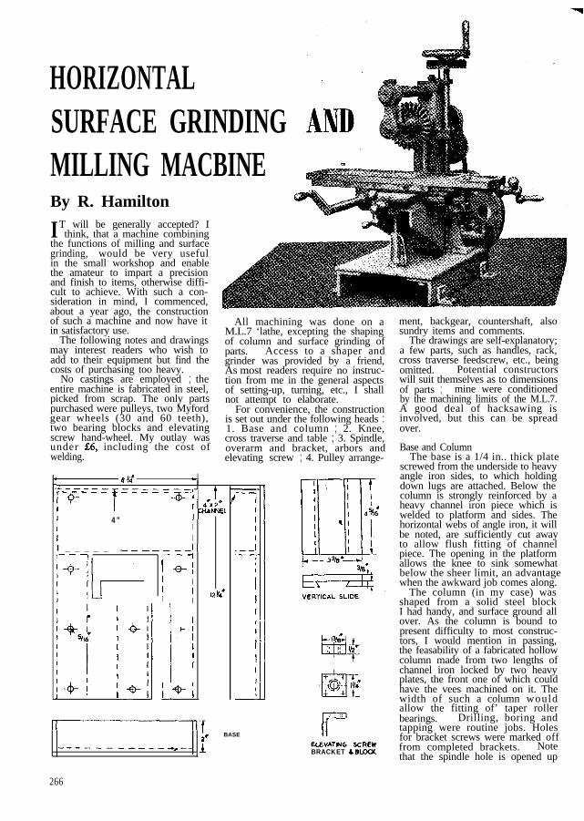
HORIZONTALSURFACE GRINDINGMILLING MACBINEBy R. Hamilton
IT will be generally accepted? Ithink, that a machine combining
the functions of milling and surfacegrinding, would be very usefulin the small workshop and enablethe amateur to impart a precisionand finish to items, otherwise diffi-cult to achieve. With such a con-sideration in mind, I commenced,about a year ago, the constructionof such a machine and now have itin satisfactory use.
The following notes and drawingsmay interest readers who wish toadd to their equipment but find thecosts of purchasing too heavy.
No castings are employed ; theentire machine is fabricated in steel,picked from scrap. The only partspurchased were pulleys, two Myfordgear wheels (30 and 60 teeth),two bearing blocks and elevatingscrew hand-wheel. My outlay wasunder $6, including the cost ofwelding.
F
All machining was done on aM.L.7 ‘lathe, excepting the shapingof column and surface grinding ofparts. Access to a shaper andgrinder was provided by a friend,As most readers require no instruc-tion from me in the general aspectsof setting-up, turning, etc., I shallnot attempt to elaborate.
For convenience, the constructionis set out under the following heads :1. Base and column ; 2. Knee,cross traverse and table ; 3. Spindle,overarm and bracket, arbors andelevating screw ; 4. Pulley arrange-
8 v4* c
c__--_;_._- _ =x=,,- t
I 7 , 4*x2*
I 4” lWNNEL
III
I _ _ _ _ _ _______I~t- - 7 ---I
j +?II
II ’ L2vee
I
I +/
I
cl
I
I 1%
cf-_ -.
I
I
.--.--2i
~
I
II-T;* BASE
------------_-_ i
266
5, ‘:rLLEVATNG SCREWBRACKET S BLCXX
ment, backgear, countershaft, alsosundry items and comments.
The drawings are self-explanatory;a few parts, such as handles, rack,cross traverse feedscrew, etc., beingomitted. Potential constructorswill suit themselves as to dimensionsof parts ; mine were conditionedby the machining limits of the M.L.7.A good deal of hacksawing isinvolved, but this can be spreadover.
Base and ColumnThe base is a 1/4 in.. thick plate
screwed from the underside to heavyangle iron sides, to which holdingdown lugs are attached. Below thecolumn is strongly reinforced by aheavy channel iron piece which iswelded to platform and sides. Thehorizontal webs of angle iron, it willbe noted, are sufficiently cut awayto allow flush fitting of channelpiece. The opening in the platformallows the knee to sink somewhatbelow the sheer limit, an advantagewhen the awkward job comes along.
The column (in my case) wasshaped from a solid steel blockI had handy, and surface ground allover. As the column is bound topresent difficulty to most construc-tors, I would mention in passing,the feasability of a fabricated hollowcolumn made from two lengths ofchannel iron locked by two heavyplates, the front one of which couldhave the vees machined on it. Thewidth of such a column wouldallow the fitting of’ taper rollerbearings. Drilling, boring andtapping were routine jobs. Holesfor bracket screws were marked offfrom completed brackets. Notethat the spindle hole is opened up

27, CYODIE
KNEE
CROSS TRAIVERSE LOWER SL IDE
Ie:35TEElY-l
PINION S H A F T
RACK PINION
I 1-NO. 2 MORSE TAPsa
0VEPARt.i WL;CKET
I CLASP N”T 6 CAM ASSEMBLY
267

August 27, 1953
to accommodate a ball thrust.The two supporting brackets
were bent (in a blacksmith’sbending machine) from 1/4 in.thick flat plate and machinedwebs welded in place. A littletiling and scraping securedgood seating on both faces,which is essential to avoid Astrain on base and column.Countersunk screws had to beused in two holes of the right-
Getzeral ariangement drawing
hand bracket to allow clear-ance for elevating feedscrew block.
Knee, Cross-traverse and TableThe knee was also bent from flat
and machined sides welded on. Itwas set up on the lathe table and edgemarked A milled. Then the hori-zontal platform was placed on thetable with the A edge lined upparallel with the table rear edge,and the vertical platform machinedby feeding it across a tool suitablyoffset in chuck. This face was nextbolted to an angle-plate, set parallelwith lathe axis (the A edge providingvertical alignment check) and thelong face likewise machined. The
BRACKET FORCOLUMN
l *
268
MILLING JIG
operator will find this quite a ticklishjob ; I fitted the tool in a blockwhich was gripped by chuck jaws.
All slides are built up, the platesand strips (5/16 in. finished thickness),being first ground on inner facesbefore countersunk riveting themtogether, to prevent warping, thenground on outer faces. Uniformityof vee-angles on plates and stripswas obtained as follows: A jig (asshown) was made and plates screweddown thereon and end milled. Thejig was lined up with the tablefront edge, packed up as required,and the angle blocks moved apart tosuit varying lengths. The holes in
The completed cross traverse andvertical-slides were secured to theknee by cap screws.
The table was -quite a job, dueto its size. After facing both sidesand end milling to square, it wasclamped to a long, broad and heavyangle-iron which was bolted to thelathe table, the whole assembly over-hanging the front of the slide withthe lower edge of the workpiece
-----
CROSS TRAVERSE TOP SLIDE
plates were plotted, as far as possible, just clearing the bed. Thus theto be used in assembly. Strips were “ T ” slots were milled out, again inactually cut off from plates, after stages. But for this operation Imilling. Additional cross-slide trav- was compelled to slide the wholeerse was obtained, when required, assembly over the table to clearby insertion of accurate distance the cut, a check bar lying againstpieces between cross-slide face and the angle-iron rear edge preservingbracket) and cuts made in stages alignment.without disturbing the workpiece. (To be concluded)

Horizontal Surface Grindingand Milling Machinee By R. Hamilton
THE trays were fashioned from suitable- channel iron, webs cut
down, and faced in lathe. Theradius on one of the webs was
the hole in the slide end being amplyopened up to clear the feedscrew.Another hole, in axial alignment, isdrilled in the opposite end of theslide. This is to permit the freepassage of the long feedscrew, whichtravels with the table and to act asa housing for the after end of thebrass tube which retains the feed-screw in its normal axis when theclasp nut is open for grindingoperations. The clasp nut is actu-ated exactly as on the. M.L.7, exceptthat the guide is square sided and notveed. Slitting of the nut was left
till the cam assembly had been fitted,which simplified the lining up of nutstuds and cam slots. Studs are ofsilver-steel.
The rack pinion and housing partsneed no comment (see GeneralArrangement “ A “). The housingis bushed and oilwayed. The handlenot shown, pulls off when not inuse, by slackening a 3/16 in. Allenscrew.
removed by end milling. Side piecesto trays were screwed in place byB.A. countersunk screws.
Clasp nut and guide assemblywere screwed into position (seeGeneral Arrangement B), then theholes through table under slideand nut drilled in one operation,
Concluded from page 268, August27, 1953.
The machine set up for horizontal milling.
320
Locking levers are fitted tovertical- and cross-slides; a longcap screw serves this purpose ontable-slide. A ram-like support (seephotographs) counters any tendencyof the knee to dip under load. Ahole requires to be drilled in theplatform to allow the plunger topass through. A flat on the plungertakes any bruising by locking thelever point.
When throwing the table duringgrinding, the clasp nut being open,the feedscrew would wobble andfoul unless retained in its noimalpath in some way. I got over thisdifficulty as follows: A brass tube,mentioned above, with an I.D. justsufficient to accommodate the 3/8in.feedscrew, has one end housed inthe hole at the after end of the slide.The other end, very slightly bell-mouthed, is soldered to a brasscradle which is screwed to nutguide and just clears the rear faceof the nut (see General ArrangementB, ‘in which the tube is shown’ inheavy black). The idea works verywell and does no damage to thescrew.
The rack was cut on the lathe asfollows: Two 1 1/4 in. (or thereabout)broad plates, 5/16 in. thick, eachfractionally over half rack length,were bolted together to an angle--plate, being packed off the angle-face by about 1 in. Angle-plate wasset on table, parallel with and behindlathe axis. A 1 1/4 in. diameter cutterwas made, with a tooth formation tofit lathe rack and mounted on amandrel between centres. The plateswere packed up so that tooth depthwas cut at one pass. An indexingdevice was made, consisting of asmall block to which was screwed ashort stiff rod, the end of which wasfiled to tooth shape. The devicewas placed on thread dial indicator

September 10, 1953
screws were drilled through rack andfixed strip in one operation. Therack is anchored to left-hand trayby a small bracket.
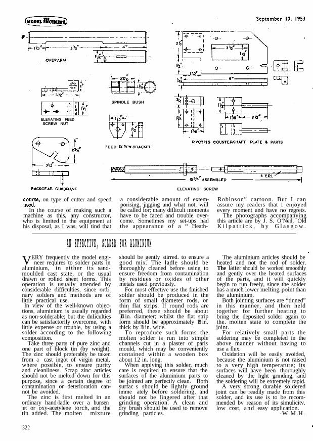
Spindle, Overarm and Bracket,. Arbors and Elevating Screw
Drawings of spindle, overarm andarbors explain themselves. All wereground finished on lathe. As canbe seen, a close. fitting dirt excludingcover is fitted at spindle front andanother can be pushed on to bracketto protect the ball thrust and race,most important requirements whengrinding. Spindle bush is of gun-metal. It is cross-slotted down tocentre-line a third way in from eachend with’ lengthwise slots on topbreaking in. A somewhat queerdesign, readers will comment, but itgives no trouble. Adjustment is byset screws through column side. Itis also oilwayed. Overarm bracketwas machined on lathe (a faceplatejob) as far as possible and finishedby filing. A ball thrust and racecombined is inserted in bracket anda gunmetal bush also fitted to actas a steadv. Lubrication cups arefitted, as shown on photographs.Milling arbor is keywayed and cutterretaining collars ground on facesat right-angle to bore. This simplemethod of locating cutters hasproved effective. Grinding wheel,with its two large collars, is locked
against the shoulder of its arborby a screwed sleeve and nut, Allen-keyed to a filed flat on arbor. Sleeveis a gas pipe union cut down.Elevating screw is in two parts,locked together by a push-out silversteel pin. Oilways are cut in collarand an oil hole drilled in collarblock. Collar block bracket andtop supporting bracket are madefrom angle-iron and on former,both faces are carefully finished sothat collar bears down perfectly.Cross traverse and elevating feed-screw nuts are replaceable.
Having no dividing head (yet), Ihand-calibrated the elevating screwindex thus : A black colouredaluminium strip (10 5/16 in.) long, waspinned to a flat board and a 12-in.rule likewise pinned against itslower edge. Using a small square Iscribed each 1/18 in., grouping everyfive and ignoring the odd one. Thestrip was pinned to a disc turned tosuitable size. As an improvisationit will serve till I have a dividing head.The pointer is held in place b y thehexagonal-headed screw which locksthe overarm.
Pulley Arrangement, Backgear,Countershaft and Sundry Items
General arrangement drawings C,D and E more or Iess remove theneed for any comments in respect
of the pulley drive, countershaftand backgear layouts. Bull wheel(60-teeth) is pitied to a steel bossand Allen-keyed to spindle.direct drive, pulley cluster is lockedto spindle by an Allen key, the pointof which enters a small groove toprevent bruising. Backgear wheels,sevarated bv a thin washer. slideon to a shouldered bush and arekey-coupled. A projecting pin onquadrant, striking column edge,prevents over-meshing. The primarydrive pulleys are mounted on theoverhung shaft. The backgear andrack pinions can be removed in afew seconds, when required for useon lathe.
The 8-in. pulley is used for milling,and when grinding, a separate beltis placed on the 4 in. one. A 1/4-h.p.motor (1,440) r.p.m., has a 1 3/4-in.milling and a 4-in. grinding pu!ley.
Milling speeds: 52, 118, 210 ahd412. Backgear 4 to 1.
Grinding speed: 2,160-secondarydrive 3 in. to 2 in.
Vibration has not troubled me,nor has overheating appeared atgrinding ‘speed. Before grinding,however, I run machine at 210 r.p.m.for a time to warm it up. I think al/3-h.p. motor would be moresuitable and maybe I shall fit onesome day. Milling cuts can betaken quite heavily, depending, of
ELEVATING FEEDSCREW NUT
jrH-!rtwSPINDLE BUSH
‘EED SCREW RRACKflCOUNTERSHAFT PLATE 6 PARTS
I/I I- 153/4nASSEMBLED ___
BACKGEAR QUiDRANT ELEVATING SCREW
~om;Se, on type of cutter and speed a considerable amount of extem- Robinson” cartoon. But I can
In the course of making such aporising, jigging and what not, will assure my readers that 1 enjoyedbe called for; many diflicult moments every moment and have no regrets.
machine as this, any constructor, have to be faced and trouble over- The photographs accompanyingwho is limited in the equipment at come. Sometimes my set-ups had this article are by J. S. O’Neil, Oldhis disposal, as I was, will tind that the appearance of a “ Heath- K i l p a t r i c k , b y G l a s g o w .
A N E F F E C T I V E , S O L D E R F O R A L U M I N I U MVERY frequently the model engi-
neer requires to solder parts inaluminium, in ei ther i ts sand-moulded cast state, or the usualdrawn or rolled sheet forms. Thisoperation is usually attended byconsiderable difficulties, since ordi-nary solders and methods are oflittle practical use.
should be gently stirred. to ensure agood mix. The ladle should bethoroughly cleaned before using toensure freedom from contaminationby residues or oxides of othermetals used previously.
For most effective use the finishedsolder should be produced in theform of small diameter rods, orthin flat strips. If round rods arepreferred, these should be about1/4 in. diameter; whilst the flat stripform should be approximately 1/8 in.thick by 3/8 in. wide.
The aluminium articles should be _heated and not the rod of solder.The latter should be worked smoothlyand gently over the heated surfacesof the parts, and it will quicklybegin to run freely, since the solderhas a much lower melting-point than
In view of the well-known objec-tions, aluminium is usually regardedas non-solderable; but the dnIicultiescan be satisfactorily overcome, withlittle expense or trouble, by using asolder according to the followingcomposition.
Take three parts of pure zinc andone part of block tin (by weight).The zinc should preferably be takenfrom a cast ingot of virgin metal,where possible, to ensure purityand cleanliness. Scrap zinc articlesshould not be melted down for thispurpose, since a certain degree ofcontamination or deterioration can-not be avoided.
The zinc is first melted in anordinary hand-ladle over a bunsenjet or oxy-acetylene torch, and thetin added. The molten mixture
322
To reproduce such forms themolten solder is run into simplechannels cut in a plaster of parismould, which may be convenientlycontained within a wooden boxabout 12 in. long.
When applying this solder, muchcare is required to ensure that thesurfaces of the aluminium parts tobe jointed are perfectly clean. Bothsurfac simme
should be lightly groundately before soldering, and
should not be fingered after thatgrinding operation. A clean anddry brush should be used to removegrinding particles.
the aluminium.Both jointing surfaces are “tinned”
in this manner, and then heldtogether for further heating tobring the deposited solder again tothe. molten state to complete thejoint.
For relatively small parts thesoldering may be completed in theabove manner without having touse a flux.
Oxidation will be easily avoided,because the aluminium is not raisedto a very high temperature; itssurfaces will have been thoroughlycleaned by the light grinding, andthe soldering will be extremely rapid.
A very strong durable solderedjoint can be readily made from thissolder, and its use is to be recom-mended bv reason of its simulicitv.low cost, and easy application.
-W.M.H.