diy kits - 3dr site scan: the complete commercial drone ... · quad diy kits thank you for...
TRANSCRIPT
QUAD
D I YK I T S
Thank you for purchasing a 3DR Quad DIY Kit!
These instructions will guide you through assembling and wiring your new autonomous multicopter.
1
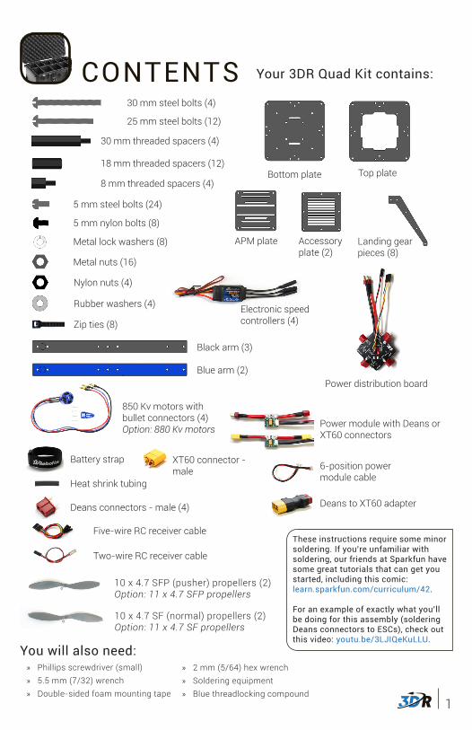
CONTENTS Your 3DR Quad Kit contains:
Metal nuts (16)
Nylon nuts (4)
5 mm nylon bolts (8)
5 mm steel bolts (24)
25 mm steel bolts (12)
30 mm steel bolts (4)
Zip ties (8)
18 mm threaded spacers (12)
Accessory plate (2)
APM plate
Top plate
Landing gear pieces (8)
You will also need:
Black arm (3)
Blue arm (2)
Battery strap
850 Kv motors with bullet connectors (4)Option: 880 Kv motors
10 x 4.7 SF (normal) propellers (2)Option: 11 x 4.7 SF propellers
10 x 4.7 SFP (pusher) propellers (2)Option: 11 x 4.7 SFP propellers
Electronic speed controllers (4)
Power distribution board
Deans to XT60 adapter
Power module with Deans or XT60 connectors
Deans connectors - male (4)
6-position power module cable
» Phillips screwdriver (small) » 5.5 mm (7/32) wrench » Double-sided foam mounting tape
These instructions require some minor soldering. If you’re unfamiliar with soldering, our friends at Sparkfun have some great tutorials that can get you started, including this comic: learn.sparkfun.com/curriculum/42.
For an example of exactly what you’ll be doing for this assembly (soldering Deans connectors to ESCs), check out this video: youtu.be/3LJIQeKuLLU.
Heat shrink tubing
Bottom plate
» 2 mm (5/64) hex wrench » Soldering equipment » Blue threadlocking compound
30 mm threaded spacers (4)
8 mm threaded spacers (4)
Metal lock washers (8)
Rubber washers (4)
Two-wire RC receiver cable
Five-wire RC receiver cable
XT60 connector - male
2
2.6
Micro USB cable
4 mm JP1 jumper connector
6 mm PPM jumper connector
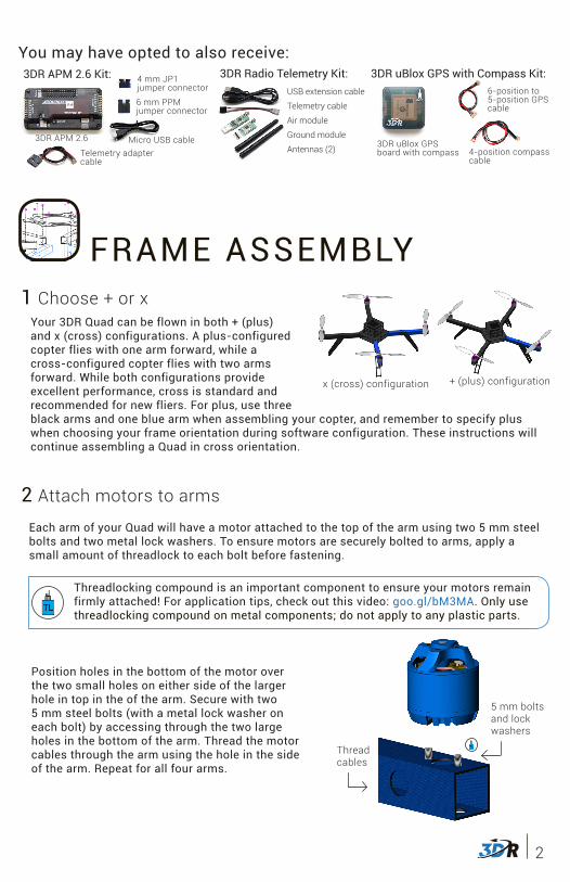
3DR APM 2.6 Kit:
You may have opted to also receive:
USB extension cable
Telemetry cable
Air module
Ground module
Antennas (2)Telemetry adapter cable
3DR APM 2.6
3DR uBlox GPS with Compass Kit:
3DR uBlox GPS board with compass
6-position to 5-position GPS cable
4-position compass cable
3DR Radio Telemetry Kit:
FRAME ASSEMBLY
2 Attach motors to arms
Each arm of your Quad will have a motor attached to the top of the arm using two 5 mm steel bolts and two metal lock washers. To ensure motors are securely bolted to arms, apply a small amount of threadlock to each bolt before fastening.
5 mm bolts and lock washers
Position holes in the bottom of the motor over the two small holes on either side of the larger hole in top in the of the arm. Secure with two 5 mm steel bolts (with a metal lock washer on each bolt) by accessing through the two large holes in the bottom of the arm. Thread the motor cables through the arm using the hole in the side of the arm. Repeat for all four arms.
Thread cables
1 Choose + or xYour 3DR Quad can be flown in both + (plus) and x (cross) configurations. A plus-configured copter flies with one arm forward, while a cross-configured copter flies with two arms forward. While both configurations provide excellent performance, cross is standard and recommended for new fliers. For plus, use three black arms and one blue arm when assembling your copter, and remember to specify plus when choosing your frame orientation during software configuration. These instructions will continue assembling a Quad in cross orientation.
x (cross) configuration + (plus) configuration
Threadlocking compound is an important component to ensure your motors remain firmly attached! For application tips, check out this video: goo.gl/bM3MA. Only use threadlocking compound on metal components; do not apply to any plastic parts.
3
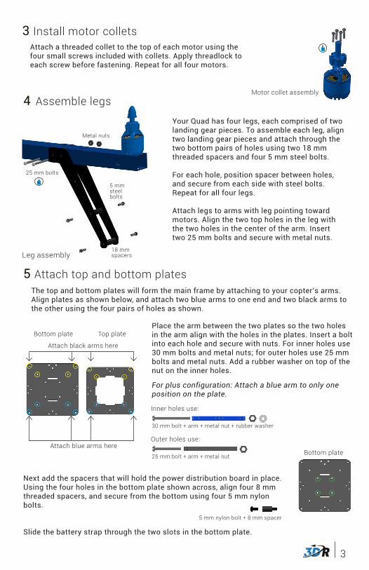
Attach a threaded collet to the top of each motor using the four small screws included with collets. Apply threadlock to each screw before fastening. Repeat for all four motors.
5 Attach top and bottom plates
Place the arm between the two plates so the two holes in the arm align with the holes in the plates. Insert a bolt into each hole and secure with nuts. For inner holes use 30 mm bolts and metal nuts; for outer holes use 25 mm bolts and metal nuts. Add a rubber washer on top of the nut on the inner holes.
For plus configuration: Attach a blue arm to only one position on the plate.
Top plateBottom plate
Next add the spacers that will hold the power distribution board in place. Using the four holes in the bottom plate shown across, align four 8 mm threaded spacers, and secure from the bottom using four 5 mm nylon bolts.
Slide the battery strap through the two slots in the bottom plate.
The top and bottom plates will form the main frame by attaching to your copter’s arms. Align plates as shown below, and attach two blue arms to one end and two black arms to the other using the four pairs of holes as shown.
Install motor collets3
Motor collet assembly
25 mm bolt + arm + metal nut
Outer holes use:
4 Assemble legs
Leg assembly
Your Quad has four legs, each comprised of two landing gear pieces. To assemble each leg, align two landing gear pieces and attach through the two bottom pairs of holes using two 18 mm threaded spacers and four 5 mm steel bolts.
For each hole, position spacer between holes, and secure from each side with steel bolts. Repeat for all four legs.
Attach legs to arms with leg pointing toward motors. Align the two top holes in the leg with the two holes in the center of the arm. Insert two 25 mm bolts and secure with metal nuts.
25 mm bolts
18 mm spacers
Metal nuts
5 mmsteelbolts
Attach black arms here
Attach blue arms here
Inner holes use:
30 mm bolt + arm + metal nut + rubber washer
Bottom plate
5 mm nylon bolt + 8 mm spacer
4
1
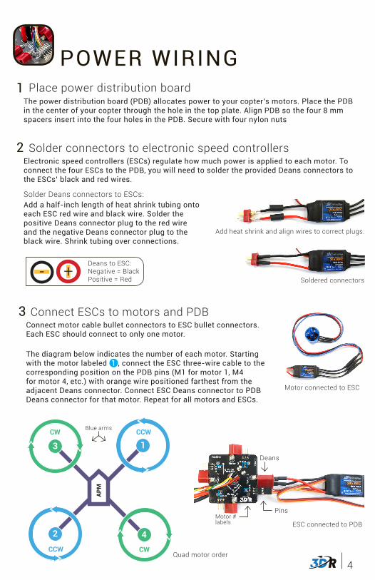
POWER WIRINGPlace power distribution board
2 Solder connectors to electronic speed controllers
The power distribution board (PDB) allocates power to your copter’s motors. Place the PDB in the center of your copter through the hole in the top plate. Align PDB so the four 8 mm spacers insert into the four holes in the PDB. Secure with four nylon nuts
Electronic speed controllers (ESCs) regulate how much power is applied to each motor. To connect the four ESCs to the PDB, you will need to solder the provided Deans connectors to the ESCs’ black and red wires.
Solder Deans connectors to ESCs:Add a half-inch length of heat shrink tubing onto each ESC red wire and black wire. Solder the positive Deans connector plug to the red wire and the negative Deans connector plug to the black wire. Shrink tubing over connections.
Add heat shrink and align wires to correct plugs.
Deans to ESC:Negative = BlackPositive = Red
- +Soldered connectors
3 Connect ESCs to motors and PDB
The diagram below indicates the number of each motor. Starting with the motor labeled 1 , connect the ESC three-wire cable to the corresponding position on the PDB pins (M1 for motor 1, M4 for motor 4, etc.) with orange wire positioned farthest from the adjacent Deans connector. Connect ESC Deans connector to PDB Deans connector for that motor. Repeat for all motors and ESCs.
APM2
CCW
1CCW
3CW
4CW
APM
1CCW
2
CCW
4CW
3CW
APM
5
CCW
4
CCW
2CCW
6CW
1CW
3
CW
APM
5CCW
2CCW
4CCW
3CW
6CW
1CW
Quad motor order
Blue arms
Motor connected to ESC
Connect motor cable bullet connectors to ESC bullet connectors. Each ESC should connect to only one motor.
ESC connected to PDB
Deans
PinsMotor #labels
5
2.6
INSTALL APM
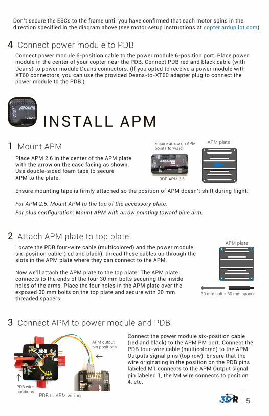
4 Connect power module to PDBConnect power module 6-position cable to the power module 6-position port. Place power module in the center of your copter near the PDB. Connect PDB red and black cable (with Deans) to power module Deans connectors. (If you opted to receive a power module with XT60 connectors, you can use the provided Deans-to-XT60 adapter plug to connect the power module to the PDB.)
1 Mount APMPlace APM 2.6 in the center of the APM plate with the arrow on the case facing as shown. Use double-sided foam tape to secure APM to the plate.
Ensure mounting tape is firmly attached so the position of APM doesn’t shift during flight.
For APM 2.5: Mount APM to the top of the accessory plate.For plus configuration: Mount APM with arrow pointing toward blue arm.
Ensure arrow on APM points forward!
3DR APM 2.6
APM plate
3 Connect APM to power module and PDBConnect the power module six-position cable (red and black) to the APM PM port. Connect the PDB four-wire cable (multicolored) to the APM Outputs signal pins (top row). Ensure that the wire originating in the position on the PDB pins labeled M1 connects to the APM Output signal pin labeled 1, the M4 wire connects to position 4, etc.
Locate the PDB four-wire cable (multicolored) and the power module six-position cable (red and black); thread these cables up through the slots in the APM plate where they can connect to the APM.
PDB to APM wiring
APM output pin positions
PDB wire positions
2 Attach APM plate to top plate
Now we’ll attach the APM plate to the top plate. The APM plate connects to the ends of the four 30 mm bolts securing the inside holes of the arms. Place the four holes in the APM plate over the exposed 30 mm bolts on the top plate and secure with 30 mm threaded spacers.
30 mm bolt + 30 mm spacer
APM plate
Don’t secure the ESCs to the frame until you have confirmed that each motor spins in the direction specified in the diagram above (see motor setup instructions at copter.ardupilot.com).
6
2.6
3DR Radio air module:Attach antenna to 3DR Radio air module. Connect telemetry cable to the air module pins (ensuring that the red wire aligns with the pin marked 5V) and to the APM Telem port.
Place the GPS module onto an accessory plate with the arrow pointing towards the center of the plate. Use double-sided foam tape to secure case to plate. Position accessory plate over the four 30 mm spacers protruding from the APM plate.
4 Mount GPSGPS module
Ensure arrow on GPS points forward!
3DR uBlox GPS with Compass: Connect the 6-position to 5-position cable to the GPS 6-position port and to the APM GPS port (use top-entry port not side-entry port). Connect the 4-position cable to the GPS 4-position port and to the APM I2C port.
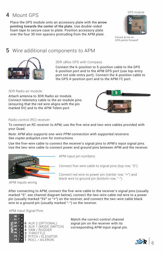
5 Wire additional components to APM
Radio control (RC) receiver:To connect an RC receiver to APM, use the five-wire and two-wire cables provided with your Quad.Note: APM also supports one-wire PPM connection with supported receivers. See copter.ardupilot.com for instructions.Use the five-wire cable to connect the receiver’s signal pins to APM’s input signal pins. Use the two-wire cable to connect power and ground pins between APM and the receiver.
APM inputs wiring
APM input pin numbers
Connect five-wire cable to signal pins (top row, “S”).
Connect red wire to power pin (center row, “+”) and black wire to ground pin (bottom row, “-”).
Match the correct control channel signal pin on the receiver with its corresponding APM input signal pin.
6 AUX 2 (OPTIONAL)5 AUX 1 (MODE SWITCH)4 YAW / RUDDER3 THROTTLE2 PITCH / ELEVATOR1 ROLL / AILERON
APM Input Signal Pins
After connecting to APM, connect the five-wire cable to the receiver’s signal pins (usually marked “S”, see channel diagram below), connect the two-wire cable red wire to a power pin (usually marked “5V” or “+“) on the receiver, and connect the two-wire cable black wire to a ground pin (usually marked “-“) on the receiver.
7
6 Attach accessory plates to APM plate
Place one accessory plate on top of the APM plate, and align the four 30 mm spacers with the four holes in the accessory plate. Secure accessory plate using four 18 mm spacers. Secure second accessory plate to the tops of the 18 mm spacers using four nylon bolts inserted into the four holes in the plate.
APM plate Accessory plate30 mm spacer + 18 mm spacer + 5 mm nylon bolt
Complete plate assembly
INSTALL SOFTWAREMission Planner is free, open-source software providing multiplatform configuration and full-featured waypoint mission scripting for autonomous vehicles.
To install Mission Planner on your ground station computer (Windows only), visit ardupilot.com/downloads, select Mission Planner, and select sort by date (short link: goo.gl/Si5grC). Select the most recent (top) MissionPlanner - MSI (Microsoft installer package).
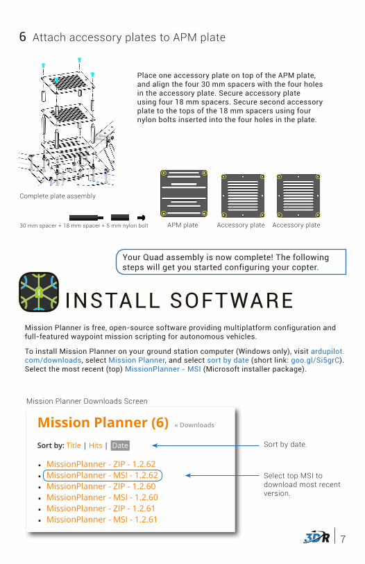
Mission Planner Downloads Screen
Mission Planner (6) « Downloads
Sort by: Title | Hits | Date
■ MissionPlanner - ZIP - 1.2.62 ■ MissionPlanner - MSI - 1.2.62 ■ MissionPlanner - ZIP - 1.2.60 ■ MissionPlanner - MSI - 1.2.60 ■ MissionPlanner - ZIP - 1.2.61 ■ MissionPlanner - MSI - 1.2.61
Sort by date.
Select top MSI to download most recent version.
Your Quad assembly is now complete! The following steps will get you started configuring your copter.
Accessory plate
8
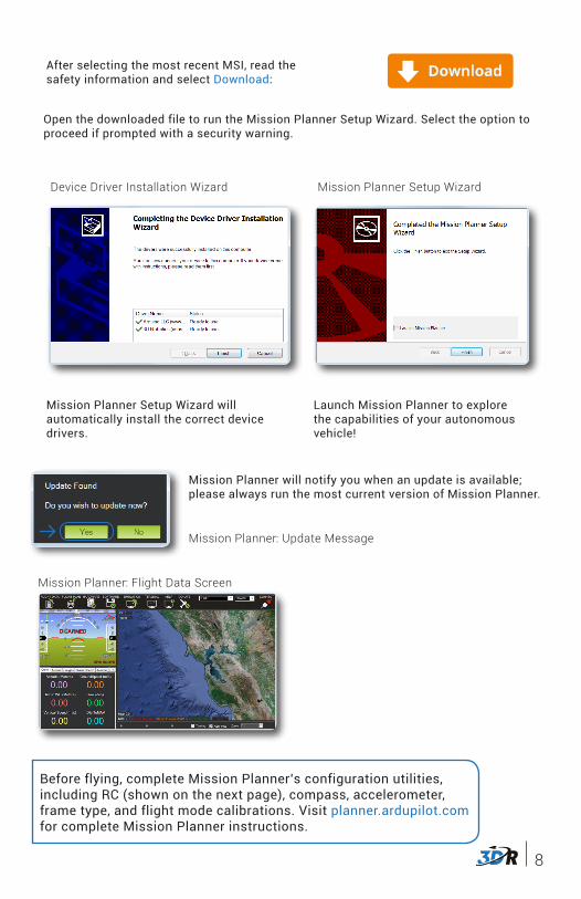
After selecting the most recent MSI, read the safety information and select Download: Download
Open the downloaded file to run the Mission Planner Setup Wizard. Select the option to proceed if prompted with a security warning.
Mission Planner Setup Wizard will automatically install the correct device drivers.
Device Driver Installation Wizard Mission Planner Setup Wizard
Launch Mission Planner to explore the capabilities of your autonomous vehicle!
Mission Planner will notify you when an update is available; please always run the most current version of Mission Planner.
Mission Planner: Update Message
Mission Planner: Flight Data Screen
Before flying, complete Mission Planner’s configuration utilities, including RC (shown on the next page), compass, accelerometer, frame type, and flight mode calibrations. Visit planner.ardupilot.com for complete Mission Planner instructions.
9
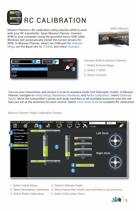
Mission Planner’s RC calibration utility teaches APM to work with your RC transmitter. Open Mission Planner. Connect APM to your computer using the provided micro-USB cable. Windows will automatically install the correct drivers for APM. In Mission Planner, select the COM port for Arduino Mega, set the Baud rate to 115200, and select Connect.
Turn on your transmitter, and ensure it is set to airplane mode (not helicopter mode). In Mission Planner, navigate to Initial Setup, Mandatory Hardware, and Radio Calibration. Select Calibrate Radio. Move the transmitter’s sticks and mode switches to all available positions until the red bars are set at the extremes for each control. Select Click when Done to complete RC calibration.
APM USB port
Connect APM to Mission Planner:
1 Select Arduino Mega.
2 Select 115200.
3 Select Connect.
1 23
Mission Planner: Radio Calibration Screen
12
3
4
5
6
Left Stick:
Right Stick:
RC CALIBRATION
1 Select Initial Setup.2 Select Mandatory Hardware.3 Select Radio Calibration.
4 Select Calibrate Radio.5 Move transmitter sticks and switches to all positions.6 Select Click when Done.
10
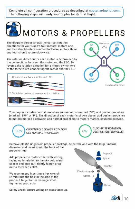
MOTORS & PROPELLERS
Prop nut
Motor
Propeller
Plastic ring
Spacer
Collet
Safety Check! Ensure writing on props faces up.
COUNTERCLOCKWISE ROTATION:USE NORMAL PROPELLER
CLOCKWISE ROTATION:USE PUSHER PROPELLER
Your copter includes normal propellers (unmarked or marked “SF”) and pusher propellers (marked “SFP” or “P“). The direction of each motor is shown above: add pusher propellers to motors marked clockwise, add normal propellers to motors marked counterclockwise.
CCW
! !CW
CCW
! !CW
CCW
! !CW
CCW
! !CW
Remove plastic rings from propeller package, select the one with the larger internal diameter, and insert it into the back of the propeller hub.
Add propeller to motor collet with writing facing up in relation to the sky. Add metal spacer and prop nut; tightly fasten prop nut to threaded collet.
We recommend inserting a hex wrench (2 mm) into the hole in the side of the prop nut to get better leverage when tightening prop nuts.
Complete all configuration procedures as described at copter.ardupilot.com. The following steps will ready your copter for its first flight.
The diagram across shows the correct rotation directions for your Quad’s four motors: motors one and two should rotate counterclockwise, motors three and four should rotate clockwise.
The rotation direction for each motor is determined by the connections between the motor and the ESC. To reverse the rotation direction for a motor, switch two of the three wires connecting the motor and the ESC.
APM2
CCW
1CCW
3CW
4CW
APM
1CCW
2
CCW
4CW
3CW
APM
5
CCW
4
CCW
2CCW
6CW
1CW
3
CW
APM
5CCW
2CCW
4CCW
3CW
6CW
1CW
Quad motor order
Blue arms
1. Connection between motor and ESC
2. Switch two wires to reverse motor rotation.
11
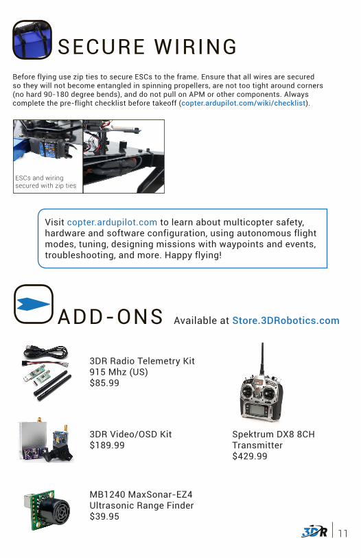
SECURE WIRINGBefore flying use zip ties to secure ESCs to the frame. Ensure that all wires are secured so they will not become entangled in spinning propellers, are not too tight around corners (no hard 90-180 degree bends), and do not pull on APM or other components. Always complete the pre-flight checklist before takeoff (copter.ardupilot.com/wiki/checklist).
ESCs and wiring secured with zip ties
Visit copter.ardupilot.com to learn about multicopter safety, hardware and software configuration, using autonomous flight modes, tuning, designing missions with waypoints and events, troubleshooting, and more. Happy flying!
ADD-ONS Available at Store.3DRobotics.com
3DR Radio Telemetry Kit 915 Mhz (US)$85.99
3DR Video/OSD Kit$189.99
MB1240 MaxSonar-EZ4 Ultrasonic Range Finder$39.95
Spektrum DX8 8CH Transmitter$429.99