division 800 incidental construction - … · table of contents division 800 incidental...
TRANSCRIPT
TABLE OF CONTENTS
DIVISION 800 INCIDENTAL CONSTRUCTION
SECTION PAGE
i
801 - MOBILIZATION ......................................................................................................................................... 800-1 802 - CONTRACTOR CONSTRUCTION STAKING ......................................................................................... 800-2 803 - FIELD OFFICE AND LABORATORY ...................................................................................................... 800-8 804 - MAINTENANCE AND RESTORATION OF HAUL ROADS ................................................................ 800-11 805 - WORK ZONE TRAFFIC CONTROL AND SAFETY ............................................................................. 800-13 806 - DURABLE PAVEMENT MARKING ...................................................................................................... 800-24 807 - PAINTED PAVEMENT MARKING ........................................................................................................ 800-30 808 - REMOVAL OF EXISTING PAVEMENT MARKINGS .......................................................................... 800-32 809 - CONCRETE SAFETY BARRIER ............................................................................................................. 800-33 810 - INERTIAL BARRIER SYSTEM ............................................................................................................... 800-35 811 - IMPACT ATTENUATOR ......................................................................................................................... 800-36 812 - PERMANENT SIGNING .......................................................................................................................... 800-38 813 - RUMBLE STRIPS (MILLED) ................................................................................................................... 800-43 814 - ELECTRIC LIGHTING SYSTEMS AND TRAFFIC SIGNALS ............................................................. 800-44 815 - CATCH BASINS, INLETS, OUTLETS, MANHOLES, JUNCTION BOXES AND OTHER EXISTING
STRUCTURES ......................................................................................................................................... 800-48 816 - ADJUSTMENT OF INLETS, MANHOLES AND OTHER EXISTING STRUCTURES........................ 800-50 817 - PIPE CULVERTS, EROSION PIPE, STORM SEWERS, SANITARY SEWERS & END SECTIONS .. 800-51 818 - ENCASEMENT PIPE ................................................................................................................................ 800-58 819 - BORED, JACKED OR TUNNELED PIPE ............................................................................................... 800-59 820 - FLUME INLETS AND SLOPE DRAINS ................................................................................................. 800-61 821 - FLAPGATES ............................................................................................................................................. 800-62 822 - UNDERDRAINS ....................................................................................................................................... 800-63 823 - PREFABRICATED INTERCEPTION DEVICES AND SLOTTED DRAINS ........................................ 800-66 824 - CONCRETE SIDEWALK, STEPS AND RAMPS .................................................................................... 800-67 825 - CURB AND GUTTER ............................................................................................................................... 800-70 826 - CONCRETE SURFACE REPAIR ............................................................................................................. 800-73 827 - GUARDRAIL AND GUIDEPOSTS ......................................................................................................... 800-75 828 - FENCING .................................................................................................................................................. 800-77 829 - RIPRAP ...................................................................................................................................................... 800-81 830 - SLOPE PROTECTION .............................................................................................................................. 800-82 831 - DITCH LINING ......................................................................................................................................... 800-84 832 - GABIONS .................................................................................................................................................. 800-85 833 - PAVEMENT PATCHING ......................................................................................................................... 800-86 834 - UNDERSEALING ..................................................................................................................................... 800-90 835 - RESEALING JOINTS AND SEALING CRACKS IN EXISTING PCCP AND HMA PAVEMENTS .. 800-92 836 - SURFACING FOR SIDE ROADS AND ENTRANCES .......................................................................... 800-96 837 - PAVEMENT WIDENING, SHOULDERING AND PAVEMENT EDGE WEDGE ................................ 800-97 838 - GRINDING REHAB CONCRETE PAVEMENT ..................................................................................... 800-99 839 - RUBBLIZING PORTLAND CEMENT CONCRETE PAVEMENT ...................................................... 800-101 840 - TEMPORARY SURFACING .................................................................................................................. 800-103 841 - LIGHT TYPE SURFACING ................................................................................................................... 800-104 842 - DRILLING AND GROUTING ................................................................................................................ 800-105 843 - FLOWABLE FILL ................................................................................................................................... 800-107 844 - SLURRY GROUT ................................................................................................................................... 800-108 845 - CLEANING EXISTING STRUCTURES AND UNDERDRAINS ......................................................... 800-110 846 - TRANSPORTING SALVAGEABLE MATERIAL ................................................................................ 800-112 847 - MAILBOX ADJUSTMENTS .................................................................................................................. 800-113 848 - ANTI-GRAFFITI COATING .................................................................................................................. 800-114 849 - GEOMEMBRANE ................................................................................................................................... 800-115 850 - SEPARATION GEOTEXTILE ................................................................................................................ 800-116 851 - PAVEMENT WATERPROOFING MEMBRANE ................................................................................. 800-117
TABLE OF CONTENTS
DIVISION 800 INCIDENTAL CONSTRUCTION
SECTION PAGE
ii
852 - PAVING FABRIC ................................................................................................................................... 800-118 853 - RETAINING WALL SYSTEM ............................................................................................................... 800-119 854 - LANDSCAPE RETAINING WALL SYSTEM ....................................................................................... 800-125 855 - SOLID INTERLOCKING PAVING UNITS (PAVING BRICKS) ......................................................... 800-129 856 - PRECAST CONCRETE PARKING BLOCK ......................................................................................... 800-130 857 - PLUGGING WELLS ............................................................................................................................... 800-131 858 - BRIDGE APPROACH SLAB FOOTING ............................................................................................... 800-132 859 - INTELLIGENT TRANSPORTATION SYSTEM (ITS) ......................................................................... 800-133 860 - BASEDRAINS ......................................................................................................................................... 800-136
801 - MOBILIZATION
800-1
SECTION 801
MOBILIZATION 801.1 DESCRIPTION Move required personnel, equipment, materials, supplies and incidentals to the project site prior to beginning work. Include other work and costs incurred before the project starts. BID ITEMS UNITS Mobilization Lump Sum Mobilization (DBE) Lump Sum
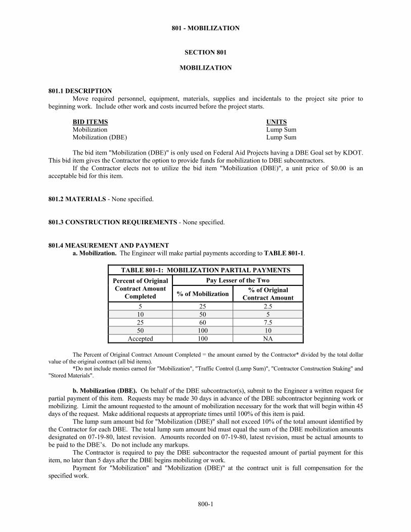
The bid item "Mobilization (DBE)" is only used on Federal Aid Projects having a DBE Goal set by KDOT. This bid item gives the Contractor the option to provide funds for mobilization to DBE subcontractors. If the Contractor elects not to utilize the bid item "Mobilization (DBE)", a unit price of $0.00 is an acceptable bid for this item. 801.2 MATERIALS - None specified. 801.3 CONSTRUCTION REQUIREMENTS - None specified. 801.4 MEASUREMENT AND PAYMENT a. Mobilization. The Engineer will make partial payments according to TABLE 801-1.
TABLE 801-1: MOBILIZATION PARTIAL PAYMENTS
Percent of Original Contract Amount
Completed
Pay Lesser of the Two
% of Mobilization % of Original
Contract Amount 5 25 2.5
10 50 5 25 60 7.5 50 100 10
Accepted 100 NA
The Percent of Original Contract Amount Completed = the amount earned by the Contractor* divided by the total dollar value of the original contract (all bid items).
*Do not include monies earned for "Mobilization", "Traffic Control (Lump Sum)", "Contractor Construction Staking" and "Stored Materials".
b. Mobilization (DBE). On behalf of the DBE subcontractor(s), submit to the Engineer a written request for
partial payment of this item. Requests may be made 30 days in advance of the DBE subcontractor beginning work or mobilizing. Limit the amount requested to the amount of mobilization necessary for the work that will begin within 45 days of the request. Make additional requests at appropriate times until 100% of this item is paid.
The lump sum amount bid for "Mobilization (DBE)" shall not exceed 10% of the total amount identified by the Contractor for each DBE. The total lump sum amount bid must equal the sum of the DBE mobilization amounts designated on 07-19-80, latest revision. Amounts recorded on 07-19-80, latest revision, must be actual amounts to be paid to the DBE’s. Do not include any markups. The Contractor is required to pay the DBE subcontractor the requested amount of partial payment for this item, no later than 5 days after the DBE begins mobilizing or work. Payment for "Mobilization" and "Mobilization (DBE)" at the contract unit is full compensation for the specified work.
802 - CONTRACTOR CONSTRUCTION STAKING
800-2
SECTION 802
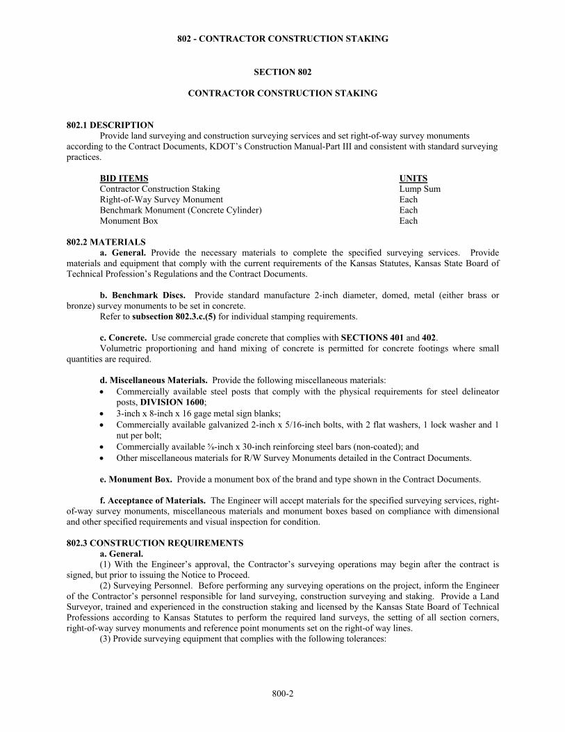
CONTRACTOR CONSTRUCTION STAKING 802.1 DESCRIPTION Provide land surveying and construction surveying services and set right-of-way survey monuments according to the Contract Documents, KDOT’s Construction Manual-Part III and consistent with standard surveying practices. BID ITEMS UNITS Contractor Construction Staking Lump Sum Right-of-Way Survey Monument Each
Benchmark Monument (Concrete Cylinder) Each Monument Box Each 802.2 MATERIALS a. General. Provide the necessary materials to complete the specified surveying services. Provide materials and equipment that comply with the current requirements of the Kansas Statutes, Kansas State Board of Technical Profession’s Regulations and the Contract Documents. b. Benchmark Discs. Provide standard manufacture 2-inch diameter, domed, metal (either brass or bronze) survey monuments to be set in concrete.
Refer to subsection 802.3.c.(5) for individual stamping requirements.
c. Concrete. Use commercial grade concrete that complies with SECTIONS 401 and 402. Volumetric proportioning and hand mixing of concrete is permitted for concrete footings where small quantities are required.
d. Miscellaneous Materials. Provide the following miscellaneous materials: Commercially available steel posts that comply with the physical requirements for steel delineator
posts, DIVISION 1600; 3-inch x 8-inch x 16 gage metal sign blanks; Commercially available galvanized 2-inch x 5/16-inch bolts, with 2 flat washers, 1 lock washer and 1
nut per bolt; Commercially available ⅝-inch x 30-inch reinforcing steel bars (non-coated); and Other miscellaneous materials for R/W Survey Monuments detailed in the Contract Documents.
e. Monument Box. Provide a monument box of the brand and type shown in the Contract Documents. f. Acceptance of Materials. The Engineer will accept materials for the specified surveying services, right-of-way survey monuments, miscellaneous materials and monument boxes based on compliance with dimensional and other specified requirements and visual inspection for condition.
802.3 CONSTRUCTION REQUIREMENTS a. General. (1) With the Engineer’s approval, the Contractor’s surveying operations may begin after the contract is signed, but prior to issuing the Notice to Proceed. (2) Surveying Personnel. Before performing any surveying operations on the project, inform the Engineer of the Contractor’s personnel responsible for land surveying, construction surveying and staking. Provide a Land Surveyor, trained and experienced in the construction staking and licensed by the Kansas State Board of Technical Professions according to Kansas Statutes to perform the required land surveys, the setting of all section corners, right-of-way survey monuments and reference point monuments set on the right-of way lines.
(3) Provide surveying equipment that complies with the following tolerances:
802 - CONTRACTOR CONSTRUCTION STAKING
800-3
Slope Staking: Horizontal and Vertical tolerance of ± 0.10 feet (per KDOT Construction Manual - Cross Sections 3.06.02). Use a GPS system, a Total Station, or a Level & Transit.
Finish Staking: (grade hubs, blue tops, string lines, etc.) and Structures: Horizontal = ± 0.05 feet; Vertical = ± 0.01 feet (per KDOT Construction Manual, subsection 3.09 - Finishing Stakes, Part III). For Horizontal, use a GPS system or a Total Station. For Vertical, use a Level or Total Stations. Do not use GPS for Vertical.
Critical Bridge Member Staking: Horizontal = ± 0.02 feet; Vertical = ± 0.01 feet (Vertical as per Construction Manual, subsection 3.09 - Finishing Stakes, Part III). For Horizontal, use a GPS system or a Total Station. For Vertical, use a Level. See subsection 802.3c.(2) for Critical Bridge Member Staking.
Right of Way Survey Monuments: For relative precision of all R/W Survey Monuments, comply with the precision expressed in the Kansas Minimum Standards for Boundary Surveys from the project coordinate data. Use a GPS system or Total Station.
Project Control Points: The relative precision of any project control point ± 0.05 feet from the project coordinate data. Use a GPS system or Total Station.
Field Notes: For all land surveying and construction staking, record 2 measurements for verification in the field notes for all PLSS corners and all project control points.
GPS equipment: Take 2 GPS measurements at a minimum interval of 2 hours with the base station at 1 or 2 project control points. Include in the field survey notebooks a copy of the site calibration. The site calibration includes an area extending a minimum of 200 feet beyond the beginning and ending of the project and the construction limits furthest offset to the left and right of the project centerline. Take a minimum of 4 calibration points or as directed by the Engineer. Use the sum of the maximum residual of the site calibration and the delta of the point being staked.
Total Stations: To verify the tolerances, record total station measurements from 2 project control points (set-up or backsight) to the point being established. Use the average of the 2 resulting coordinate values for the point being staked for the specified tolerances.
Levels: Record in the field notes a turn through each project benchmark as they are encountered during staking activities (per KDOT Construction Manual, subsection - 3.23.05 – Elevations, Part III).
Control Stakes: Do not perform vertical control using GPS.
(4) Before proceeding with the field surveys, provide the Engineer with a written report of any errors or apparent discrepancies found in previous surveys or the Contract Documents. The Engineer will provide the corrections or necessary interpretations. Correct any deficient engineering layout or construction work that is the result of inaccuracies in the Contractor’s surveys or staking operations, or the failure to report inaccuracies found in the work previously done by KDOT, at no additional cost to KDOT. (5) The Engineer will perform final checks, measurements and surveys involving the determination of any pay quantities. The Engineer may check the accuracy and control of the Contractor’s construction staking at any time throughout the duration of the project. b. Land Surveying. (1) Before any construction activity starts in the immediate area of an endangered Public Land Survey System (PLSS) corner, recover all endangered section corners and accessories of the PLSS on the project. Endangered PLSS corners are those as defined by Kansas Statutes and/or shown in the Contract Documents as lying within the range from the project centerline to a distance 100 feet outside the construction limits, throughout the length of the project. Establish a minimum of 3 reference ties for each endangered PLSS corner. Each reference tie shall be a direct measurement to a precise (hard defined) point. Specify slope or horizontal measurement. Complete a Land Survey Reference Report marked as a "Notice of Endangerment Activity" for each endangered PLSS corner. File the reports with the appropriate governmental custodian responsible for maintaining those records, as required by Kansas Statutes. Provide the Engineer with copies of the completed reports. (2) Before any construction activity starts in the immediate area, clearly establish the right-of-way as shown in the Contract Documents. If the R/W Survey Monuments are set initially, determine each monument’s position with the project coordinates, project stationing and offset. Provide the Engineer with a written report of each monument’s position for each R/W Survey Monument set supplementary to those shown in the Contract
802 - CONTRACTOR CONSTRUCTION STAKING
800-4
Documents including additional monuments, monuments requested by the Engineer and monuments offset near obstructions. (3) Recover and verify, or reset all of the PLSS corners previously reported as endangered PLSS corners. Verify the top of all PLSS corners monuments are ¼ to ½ inch below the finish grade on concrete pavement and 4 to 6 inches below the finish grade on asphalt pavement. Establish a minimum of 3 reference ties for each of the PLSS corners. Each reference tie shall be a direct measurement to a precise (hard defined) point. Specify slope or horizontal measurement. Complete a Land Survey Reference Report marked as a Notice of Completion of Endangerment Activity and Report of Restoration for each restored PLSS corner previously reported as endangered. File the reports with the appropriate governmental custodian responsible for maintaining those records, as required by Kansas Statutes. Provide the Engineer with copies of the completed reports. (4) Before the completion of project construction, set all of the R/W Survey Monuments shown in the Contract Documents. If the R/W Survey Monuments were set initially, visually inspect each R/W Survey Monument to determine if it was either disturbed or destroyed. Reset all of the R/W Survey Monuments that are determined as disturbed or destroyed, at no cost to KDOT. Determine each reset monument’s position with both the project coordinates and the project stationing and offset. Provide the Engineer with a written report of all right-of-way survey monuments set.
c. Construction Surveying and Staking. (1) General.
Check alignment and reference or re-reference all necessary control points. Establish or re-establish project centerline. Run a level circuit to check or re-establish plan benchmarks; set other benchmarks as needed. Take original cross-sections that are not incorporated in the plans. Stake or re-stake right-of-way where needed (to be done by a Licensed Professional Land Surveyor). Perform all construction layout and reference staking necessary for the proper control and satisfactory
completion of all structures, grading, paving, drainage and all other appurtenances required for the completion of the work and acceptance of the project.
Construction of ditches and other planned excavation and embankment designated in the Contract Documents may be performed by Global Positioning System (GPS) controlled grading equipment, according to the Contract Documents and this specification. GPS controlled grading equipment does not eliminate the need for finish staking or blue top staking. Once a week, provide the Engineer with documentation (on a preapproved form) verifying machine calibration to monitor, verify, adjust and compensate for the wearing surface of the cutting edge of the machine being utilized.
(a) GPS Equipment. Use GPS controlled grading equipment capable of meeting the end results specified in the Contract Documents. The Engineer may require verification of shot locations. This could be by witnessing the Contractor take shots with GPS Rover, etc. Make available a GPS Rover (same brand and type being used on the project) to the Engineer for review of the work, as needed during normal working hours. This GPS Rover will be stored and maintained by the Contractor. In addition, provide a minimum of 8 hours of formal training on the use of the Contractor’s GPS systems to the Engineer, prior to beginning any GPS controlled machine grading. Conduct training to provide the Engineer with an understanding of the equipment, software and electronic data being used by the Contractor. For multi-year projects, the Engineer may require informal refresher-training on the use of the GPS Rover. (b) Electronic Design Files/GPS Model. When available, KDOT will provide Electronic Design Files for the project. Convert the files provided by KDOT into the format required by the Contractor’s system and equipment. Conform to the typical sections. Notify KDOT Design and the Field Office administering the contract, in writing, of any errors, omissions, ambiguities, or perceived inadequacies found in the Electronic Design Files provided by KDOT. Make no claim on the contract under SECTION 104, for additional money, additional time or both because the KDOT produced plans differ from drawings generated from the Electronic Design Files, even if the Contractor did not manipulate the Electronic Design Files before generating the GPS Model. Accept sole responsibility for the adequacy and accuracy of all Contractor-generated, subcontractor-generated, or supplier-generated documents or GPS Models
802 - CONTRACTOR CONSTRUCTION STAKING
800-5
used on the project. Assume the risk of errors and omissions resulting from software conversions, Electronic Design File manipulation or other Electronic Design File creation used by the Contractor, subcontractors, suppliers or any combination thereof. The GPS Model the Contractor generates from the Electronic Design Files may differ from the Contract Documents. The Contractor assumes the risk of such discrepancies. KDOT printed plans controls over the related Electronic Design File(s) which controls over the Contractor’s GPS Model. (c) GPS 3D Model. Before beginning any GPS controlled machine grading, provide the KDOT Field Office and KDOT Design with an electronic copy of the GPS 3D Model created for that use. In addition to the GPS machine control, provide centerline stakes, slope stakes and grade stakes from the beginning thru the end of the project, at 500-foot intervals on straight runs, and at 250-foot intervals on curves, transitions, intersections, interchanges and break points. The Engineer may require closer staking intervals for other locations, such as transition areas. GPS controlled machine grading does not eliminate the need for finish staking or blue top staking. The Engineer may review the Contractor’s GPS machine control grading results, surveying calculations, records, field procedures and actual staking at any time. If the Engineer determines the work is not meeting the required horizontal and vertical tolerances, see Unacceptable Work, SECTION 105. Contractor delays or errors due to operating the GPS machine control system will not result in any adjustment under SECTION 104, for additional money, additional time or both.
(2) Bridge. Prior to construction, set project control points and Critical Bridge Element control points for the horizontal and vertical location of the Critical Bridge Element features under the supervision of a Licensed Professional Land Surveyor. Critical Bridge Elements include, but are not limited to the features listed in TABLE 802-1.
Prior to construction, provide an independent survey performed under the supervision of a different Licensed Professional Land Surveyor to check the accuracy of the original survey of project control points and locations of the Critical Bridge Elements features.
Report any differences or discrepancies to the Project Engineer. Resolve any differences or discrepancies, prior to construction of the Critical Bridge Elements. After the Critical Bridge Elements have been constructed, provide a survey under the supervision of a
Licensed Professional Land Surveyor to verify the locations and elevations of the Critical Bridge Elements. All surveys shall be within the tolerances for that bridge element allowed in the Contract Documents.
Report any discrepancies in excess of the tolerances to the Project Engineer.
TABLE 802-1: CRITICAL BRIDGE ELEMENTS
Critical Element Critical Component(s) Spread Footing Location & Elevation of CL
Pile Cap Footing Location & Elevation of CL Drilled Shaft Location & Elevation of Center
Drilled Shaft Cap Location & Elevation of CL
Column Location & Elevation of Center
Pile Bent with Web Wall Location & Elevation of CL
Abutment Beam/Bearing Seat Location & Elevation of CL
Pier Beam/Bearing Seat Location & Elevation of CL
Bearing Devices Location & Elevation of CL, Temp. OffsetBearing Stiffener Location & Elevation of CL, Temperature Offset
Girder/Beam Location of CL
Anchor Bolts/Preformed Holes Location of CL
Expansion Device Gap (Corrected for Temp) and AlignmentFillets (Tenth Points) Elevation
Surface of Forms (Slab Bridge Tenth Points) Elevation
Post-tensioning Duct Location & Elevation
Bolted Field Splice Elevation
(3) Documentation. Provide and maintain a current copy of all field survey notebooks at the project site at all times. Produce the original field survey notebooks for inspection upon request by the Engineer. Include a
802 - CONTRACTOR CONSTRUCTION STAKING
800-6
detailed list of any abbreviations, codes, formatting or other nomenclature contained in the notebooks to facilitate clarity of the notes. Provide either one or a combination of both of the following types of notes, as directed by the Engineer:
Provide standard, bound field notebooks where the handwritten field notes are indexed and kept in a clear, orderly and neat manner consistent with standard surveying practices and according to KDOT’s procedures.
Provide a legible ASCII file for electronic field notes where the “theoretical (calculated) point” can be checked against the “established point” set in the field. This method allows for a check of the inverse distance and direction for error tolerance. This procedure should be utilized for points with elevations. Before any construction staking begins, the procedures for all electronic field notes must be approved by the Engineer.
(4) Monuments. Upon completion of the surfacing, recover and verify or reset all of the field survey
monuments (such as P.I.’s, P.O.T.’s, P.C.’s, P.T.’s, P.O.S.T.’s,) on the project centerlines or baselines, as shown in the Contract Documents. Verify that the top of the field survey monuments are set a maximum of ½ inch below the finish grade on concrete pavement, or a maximum of 6 inches below the finish grade on asphalt pavement. Verify the accuracy of the locations of all field survey monuments versus those of the project centerlines or baselines shown in the Contract Documents. Establish a minimum of 4 reference ties for each of the field survey monuments on the project centerlines or baselines. (5) Reports. Provide a written report to the Engineer indicating the descriptions of all field survey monuments and their 4 reference ties, regardless if the information in the Contract Documents was revised or not. Include in the report “station calls” for each of the field survey monuments (such as P.I.’s, P.O.T.’s, P.C.’s, P.T.’s, P.O.S.T.’s) on the project centerlines or baselines shown in the Contract Documents. Recover and verify all of the project benchmarks shown in the Contract Documents. Establish permanent replacement benchmarks for all project benchmarks that were destroyed during the construction using one of these methods:
A benchmark disc “set in place” on new concrete structure. A benchmark disc “drilled and grouted” on existing concrete structure. A benchmark disc set in the top of a concrete footing (6-inch diameter x 4-foot depth into the ground,
minimum) cast in place. As directed by the Engineer. Stamp the benchmark caps with the “Project Number” and the permanent replacement benchmark number
as a letter designation following the benchmark it is replacing (i.e.: destroyed BM #21 is replaced by BM #21A). Without exception verify that the maximum spacing between benchmarks is a maximum of 30 feet in vertical difference, 500 feet in horizontal distance in urban areas or 1500 feet in horizontal distance in rural areas.
Provide the Engineer with a written report of all post project benchmarks, listing the benchmark number, elevation, project stationing and offset, and a complete description of the monument type and its physical location. Include in the report, all of the remaining benchmarks shown in the Contract Documents, the permanent replacement benchmarks and the remaining additional “construction benchmarks” used for the staking of the project. Do not include in the report any “temporary benchmarks” used for the construction staking of the project that are classified as “temporary” or “degradable” in nature. d. Right-of-Way Survey Monuments. Set all right-of-way survey monuments on and along the KDOT right-of-way lines at these locations:
All P.I. locations along normal/tangent sections. All P.C. and P.T. locations along curved sections. At an offset where a physical obstruction impedes the exact location. Set all Reference Point monuments on and along KDOT right-of-way at these locations: At points a maximum of 1320 feet apart where the right-of-way is straight, or on a continuous horizontal
curve of constant radius. At the crest of a sharp hill or the shoulders of a large/rounded hill. At radial/perpendicular lines to all horizontal changes in the project centerline alignment (i.e., P.C. and
P.T. offsets). As directed by the Engineer.
802 - CONTRACTOR CONSTRUCTION STAKING
800-7
Set all right-of-way survey monuments according to the Contract Documents.
Fasten the R/W sign to the witness post in this sequence: bolt, flat washer, sign, post, flat washer, lock washer and nut. When conditions warrant, the Engineer may adjust the specified depth. When it is impossible to set a right-of-way survey monument at the exact point because of an obstruction, set the right-of-way survey monument along the right-of-way line, or the extended right-of-way line, on both sides of the obstruction. Use 1-foot increments for the offset distance from the exact point to the set monument. Field stamp the aluminum cap “O/S” either below or to the right of the “R/W” stamping. Provide the Engineer with a complete list of the locations of all right-of-way survey monuments set.
e. Concrete Footings. When required, construct footings of commercial grade concrete according to the Contract Documents. Extend the top of the footing slightly above the ground line and steel trowel to a smooth finish with a slope to drain away from the post. f. Monument Box. When required, install the monument box and survey marker by a Licensed Professional Land Surveyor as shown in the Contract Documents. If the monument box is installed in concrete pavement, use the same mix as used in the pavement. g. As-Built Construction Plans and Survey Notebooks. Upon completion of the project, provide the Engineer with a set of as-built construction plans with the following information:
The monument descriptions and the 3 reference ties for all restored PLSS corners. The monument descriptions and the 4 reference ties for all field survey monuments on the project
centerline or baseline. The project stationing and offset of the final position of every right-of-way survey monument and
project alignment reference point that was set. The permanent replacement benchmarks and remaining construction benchmarks with benchmark
number, project station and offset, elevation and description. Deliver the original field survey notebooks to the Engineer upon completion of the project.
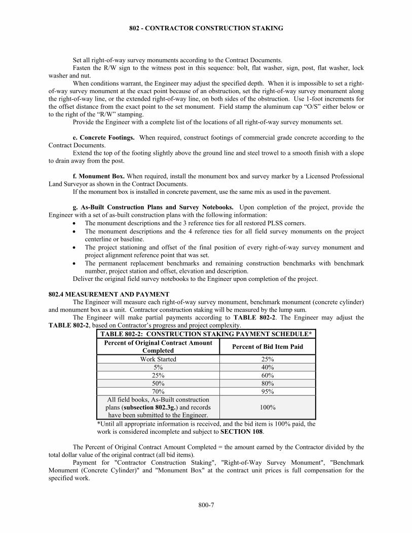
802.4 MEASUREMENT AND PAYMENT The Engineer will measure each right-of-way survey monument, benchmark monument (concrete cylinder)
and monument box as a unit. Contractor construction staking will be measured by the lump sum. The Engineer will make partial payments according to TABLE 802-2. The Engineer may adjust the
TABLE 802-2, based on Contractor’s progress and project complexity. TABLE 802-2: CONSTRUCTION STAKING PAYMENT SCHEDULE*
Percent of Original Contract Amount Completed
Percent of Bid Item Paid
Work Started 25% 5% 40% 25% 60% 50% 80% 70% 95%
All field books, As-Built construction plans (subsection 802.3g.) and records have been submitted to the Engineer.
100%
*Until all appropriate information is received, and the bid item is 100% paid, the work is considered incomplete and subject to SECTION 108.
The Percent of Original Contract Amount Completed = the amount earned by the Contractor divided by the total dollar value of the original contract (all bid items).
Payment for "Contractor Construction Staking", "Right-of-Way Survey Monument", "Benchmark Monument (Concrete Cylinder)" and "Monument Box" at the contract unit prices is full compensation for the specified work.
803 - FIELD OFFICE AND LABORATORY
800-8
SECTION 803
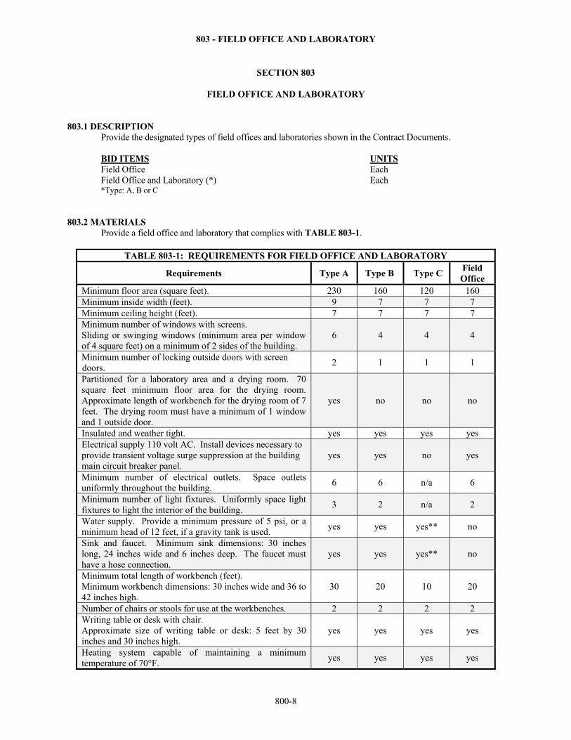
FIELD OFFICE AND LABORATORY 803.1 DESCRIPTION Provide the designated types of field offices and laboratories shown in the Contract Documents. BID ITEMS UNITS Field Office Each Field Office and Laboratory (*) Each *Type: A, B or C 803.2 MATERIALS Provide a field office and laboratory that complies with TABLE 803-1.
TABLE 803-1: REQUIREMENTS FOR FIELD OFFICE AND LABORATORY
Requirements Type A Type B Type C Field Office
Minimum floor area (square feet). 230 160 120 160 Minimum inside width (feet). 9 7 7 7 Minimum ceiling height (feet). 7 7 7 7 Minimum number of windows with screens. Sliding or swinging windows (minimum area per window of 4 square feet) on a minimum of 2 sides of the building.
6 4 4 4
Minimum number of locking outside doors with screen doors.
2 1 1 1
Partitioned for a laboratory area and a drying room. 70 square feet minimum floor area for the drying room. Approximate length of workbench for the drying room of 7 feet. The drying room must have a minimum of 1 window and 1 outside door.
yes no no no
Insulated and weather tight. yes yes yes yes Electrical supply 110 volt AC. Install devices necessary to provide transient voltage surge suppression at the building main circuit breaker panel.
yes yes no yes
Minimum number of electrical outlets. Space outlets uniformly throughout the building.
6 6 n/a 6
Minimum number of light fixtures. Uniformly space light fixtures to light the interior of the building.
3 2 n/a 2
Water supply. Provide a minimum pressure of 5 psi, or a minimum head of 12 feet, if a gravity tank is used.
yes yes yes** no
Sink and faucet. Minimum sink dimensions: 30 inches long, 24 inches wide and 6 inches deep. The faucet must have a hose connection.
yes yes yes** no
Minimum total length of workbench (feet). Minimum workbench dimensions: 30 inches wide and 36 to 42 inches high.
30 20 10 20
Number of chairs or stools for use at the workbenches. 2 2 2 2 Writing table or desk with chair. Approximate size of writing table or desk: 5 feet by 30 inches and 30 inches high.
yes yes yes yes
Heating system capable of maintaining a minimum temperature of 70°F.
yes yes yes yes
803 - FIELD OFFICE AND LABORATORY
800-9
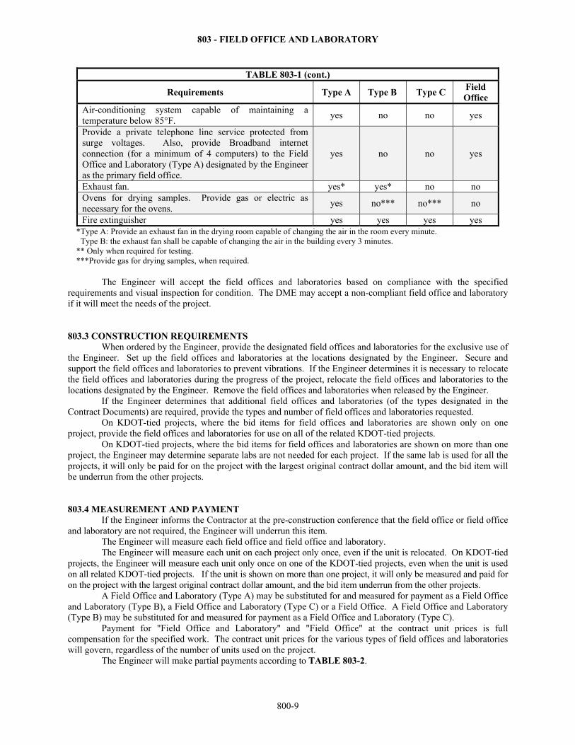
TABLE 803-1 (cont.)
Requirements Type A Type B Type C Field Office
Air-conditioning system capable of maintaining a temperature below 85°F.
yes no no yes
Provide a private telephone line service protected from surge voltages. Also, provide Broadband internet connection (for a minimum of 4 computers) to the Field Office and Laboratory (Type A) designated by the Engineer as the primary field office.
yes no no yes
Exhaust fan. yes* yes* no no Ovens for drying samples. Provide gas or electric as necessary for the ovens.
yes no*** no*** no
Fire extinguisher yes yes yes yes *Type A: Provide an exhaust fan in the drying room capable of changing the air in the room every minute. Type B: the exhaust fan shall be capable of changing the air in the building every 3 minutes. ** Only when required for testing. ***Provide gas for drying samples, when required.
The Engineer will accept the field offices and laboratories based on compliance with the specified requirements and visual inspection for condition. The DME may accept a non-compliant field office and laboratory if it will meet the needs of the project. 803.3 CONSTRUCTION REQUIREMENTS When ordered by the Engineer, provide the designated field offices and laboratories for the exclusive use of the Engineer. Set up the field offices and laboratories at the locations designated by the Engineer. Secure and support the field offices and laboratories to prevent vibrations. If the Engineer determines it is necessary to relocate the field offices and laboratories during the progress of the project, relocate the field offices and laboratories to the locations designated by the Engineer. Remove the field offices and laboratories when released by the Engineer. If the Engineer determines that additional field offices and laboratories (of the types designated in the Contract Documents) are required, provide the types and number of field offices and laboratories requested. On KDOT-tied projects, where the bid items for field offices and laboratories are shown only on one project, provide the field offices and laboratories for use on all of the related KDOT-tied projects. On KDOT-tied projects, where the bid items for field offices and laboratories are shown on more than one project, the Engineer may determine separate labs are not needed for each project. If the same lab is used for all the projects, it will only be paid for on the project with the largest original contract dollar amount, and the bid item will be underrun from the other projects. 803.4 MEASUREMENT AND PAYMENT
If the Engineer informs the Contractor at the pre-construction conference that the field office or field office and laboratory are not required, the Engineer will underrun this item. The Engineer will measure each field office and field office and laboratory.
The Engineer will measure each unit on each project only once, even if the unit is relocated. On KDOT-tied projects, the Engineer will measure each unit only once on one of the KDOT-tied projects, even when the unit is used on all related KDOT-tied projects. If the unit is shown on more than one project, it will only be measured and paid for on the project with the largest original contract dollar amount, and the bid item underrun from the other projects. A Field Office and Laboratory (Type A) may be substituted for and measured for payment as a Field Office and Laboratory (Type B), a Field Office and Laboratory (Type C) or a Field Office. A Field Office and Laboratory (Type B) may be substituted for and measured for payment as a Field Office and Laboratory (Type C).
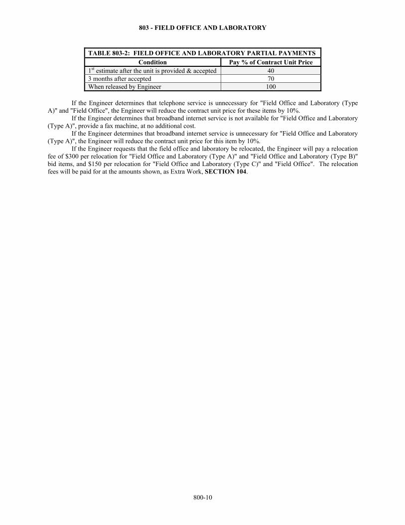
Payment for "Field Office and Laboratory" and "Field Office" at the contract unit prices is full compensation for the specified work. The contract unit prices for the various types of field offices and laboratories will govern, regardless of the number of units used on the project. The Engineer will make partial payments according to TABLE 803-2.
803 - FIELD OFFICE AND LABORATORY
800-10
TABLE 803-2: FIELD OFFICE AND LABORATORY PARTIAL PAYMENTS Condition Pay % of Contract Unit Price
1st estimate after the unit is provided & accepted 40 3 months after accepted 70 When released by Engineer 100
If the Engineer determines that telephone service is unnecessary for "Field Office and Laboratory (Type
A)" and "Field Office", the Engineer will reduce the contract unit price for these items by 10%. If the Engineer determines that broadband internet service is not available for "Field Office and Laboratory
(Type A)", provide a fax machine, at no additional cost. If the Engineer determines that broadband internet service is unnecessary for "Field Office and Laboratory
(Type A)", the Engineer will reduce the contract unit price for this item by 10%. If the Engineer requests that the field office and laboratory be relocated, the Engineer will pay a relocation
fee of $300 per relocation for "Field Office and Laboratory (Type A)" and "Field Office and Laboratory (Type B)" bid items, and $150 per relocation for "Field Office and Laboratory (Type C)" and "Field Office". The relocation fees will be paid for at the amounts shown, as Extra Work, SECTION 104.
804 - MAINTENANCE AND RESTORATION OF HAUL ROADS
800-11
SECTION 804
MAINTENANCE AND RESTORATION OF HAUL ROADS
804.1 DESCRIPTION Maintain and restore public roads used as haul roads for construction materials. For the purpose of this specification and when the bid item is included in the Contract Documents, a haul road is any public road in Kansas, excluding State highways over which material is hauled for the construction of the project. The most direct route to the nearest state highway that is used for hauling commercial material into or from a commercially established plant site is not designated as part of the haul road. Roads into and from quarries are not designated as part of the haul road.
When the bid item is not included in the Contract Documents, any haul road repair is subsidiary to the other items in the Contract Documents. BID ITEM UNITS Maintenance and Restoration of Haul Roads (Set Price) Lump Sum 804.2 MATERIALS Provide the type of materials necessary to maintain and restore the haul road to its condition before the hauling begins. The Engineer will accept the materials used based on visual inspection at the point of usage. 804.3 CONSTRUCTION REQUIREMENTS Provide the Engineer with a written description of the designated haul roads. The description shall include, materials being delivered, materials hauled to the project site and return routes from the project site. The Engineer will notify the owners of the roads (city and county) of the Contractor’s designations. Allow the Engineer sufficient time to inspect the designated haul roads before they are used. The Engineer, the Contractor and the owner of the roads (at their discretion) will jointly inspect the designated haul roads before they are used. The Engineer will document any deficiencies or special conditions regarding the existing roads and structures. During the hauling operations, use only designated haul roads. Observe legal weight limits and speed limits. Provide an adequate water supply and apply the water as needed to control dust. Control dust on active haul roads including return routes, in pits and staging areas, and on the project. Perform preventative and repair maintenance as necessary to minimize the damage to the haul roads. After the hauling operations are concluded, the Engineer, the Contractor and the owner of the roads (at their discretion) will jointly inspect the designated haul roads. The Engineer will review the results of the initial and final inspections, and will consider the impact of other parties that used the haul roads. Upon consideration of all these factors, the Engineer will determine the extent of restoration necessary to return the haul roads to their conditions at the time of the initial inspections. Restore the haul roads as directed by the Engineer. 804.4 MEASUREMENT AND PAYMENT When the Maintenance and Restoration of Haul Roads (Set Price) bid item is included in the Contract Documents, and the Contractor uses the designated haul roads, the Engineer will measure maintenance and restoration as a lump sum. This measurement for payment is made regardless of whether or not it is necessary for the Contractor to perform any maintenance or restoration. When the bid item is not included in the Contract Documents, any haul road repair is subsidiary to the other items in the Contract Documents. If the bid item is in the contract and the Contractor does not designate any haul roads, no measurement for payment is made.
If the bid item is in the contract and the Contractor designates haul roads but does not use any, no measurement for payment is made.

804 - MAINTENANCE AND RESTORATION OF HAUL ROADS
800-12
If the Contractor uses haul roads (as defined in this specification) other than those designated, payment for "Maintenance and Restoration of Haul Roads (Set Price)" is forfeited. The Engineer will require that the Contractor restore the undesignated haul roads to their approximate condition before hauling to the project began. The Engineer will determine the extent of restoration necessary. Payment for "Maintenance and Restoration of Haul Roads (Set Price)" at the contract unit price is full compensation for the specified work.
805 - WORK ZONE TRAFFIC CONTROL & SAFETY
800-13
SECTION 805
WORK ZONE TRAFFIC CONTROL AND SAFETY
805.1 DESCRIPTION
Provide, erect, maintain and remove traffic control devices as shown in the Contract Documents.
BID ITEMS UNITS Work Zone Signs (0 to 9.25 Sq. Ft.) Each Per Day Work Zone Signs (9.26 to 16.25 Sq. Ft.) Each Per Day Work Zone Signs (16.26 Sq. Ft. and over) Each Per Day Work Zone Sign (Special) (**) Each Work Zone Barricades (Type 3 – 4 to 12 Lin. Ft.) Each Per Day Work Zone Barricades (Pedestrian) Each per Day Arrow Display Each Per Day Portable Changeable Message Sign Each Per Day Channelizer (Fixed) Each Per Day Channelizer (Portable) Each Per Day Channelizer (Pedestrian) Each per Day Work Zone Warning Light (Type “A” Low Intensity) Each Per Day Work Zone Warning Light (Red Type “B” High Intensity) Each Per Day Pavement Marking (Temporary) 4" Solid (*) Sta./Line 4" Broken (8 ft.) (*) Sta./Line
4" Broken (3 ft.) (*) Sta./Line 4" Dotted Extension (*) Sta./Line Broken (Line Masking Tape) Sta./Line Solid (Line Masking Tape) Sta./Line Symbol (*) Each
Flexible Raised Pavement Marker (4" Broken (8 ft.)) Sta./Line Flexible Raised Pavement Marker (4" Broken (3 ft.)) Sta./Line Rigid Raised Pavement Marker (*) Each Flagger (Set Price) Hour Traffic Signal Installation (Temporary) Lump Sum Traffic Control Lump Sum Traffic Control (Initial Setup) Lump Sum *Type (Type I or II) **Size
805.2 MATERIALS
Provide materials as shown in the Contract Documents that comply with the following requirements. Retroreflective Sheeting ……….………………………………………………. DIVISION 2200 Portable Changeable Message Signs…………………………………………… DIVISION 1700 Work Zone Warning Lights…………………………………………………….. DIVISION 1700 Temporary Pavement Marking/Line Masking Tape…………………………… DIVISION 2200 Traffic Line Paint……………………………………………………………….. DIVISION 2200 Raised Pavement Markers…………………………..………………………….. DIVISION 2200 a. General. The size, shape, color, placement, installation, and maintenance of all traffic control devices
and appurtenances shall comply with the details shown in the Contract Documents and the Manual on Uniform Traffic Control Devices (MUTCD).
Use crashworthy supports used for mounting signs or devices for temporary conditions that comply with AASHTO MASH. All traffic control devices shall be tested and found acceptable using test methods compliant with

805 - WORK ZONE TRAFFIC CONTROL & SAFETY
800-14
MASH testing requirements. Devices that were accepted under the NCHRP 350 testing requirements prior to the adoption of MASH criteria may remain in place and continue to be used. Provide the following to the Engineer for a case by case approval of traffic control devices not addressed in the Contract Documents:
(1) A copy of the manufacturer’s self certification stating that the Category 1 devices to be used on the project are crashworthy.
(2) A copy of the entire FHWA acceptance letter for the Category 2 devices to be used on the project. (3) A copy of the entire FHWA acceptance letter for the Category 3 truck mounted attenuators (TMAs) to
be used on the project and certification stating that the Category 3 items to be used on the project meet crashworthy specifications, as defined above.
b. Work Zone Signs. The size and layout of the sign message shall comply with the Contract Documents and the “Standard Highway Signs and Markings”, latest edition. Use fluorescent orange Type IV or better sheeting for all work zone orange signs. Use standard colors in Type III sheeting or better for all other work zone signs. Opaque, fluorescent orange Type IV or better, roll up signs may be used in approved situations. Do not use mesh signs.
c. Work Zone Barricades. Size and design of all work zone barricades, including those used for pedestrian closures, shall comply with the Contract Documents. Provide Type 3 barricades with ASTM Type III orange and white retroreflective sheeting, as shown in the Contract Documents. Provide pedestrian barricades with orange and white high contrast sheeting as shown in the Contract Documents.
d. Flashing or Sequencing Arrow/Warning Display Signs. When specified, provide, install and maintain
a flashing or sequencing arrow/warning display sign that complies with the Contract Documents and the MUTCD. Provide a display that is capable of being legible for a minimum of ½ mile. Displays shall have an
automatic control for lamp intensity, backed up by a manual switch and be capable of dimming 50% from the rated lamp voltage for nighttime operation. The display shall be capable of flashing lamps at a rate between 25 and 40 flashes per minute.
The minimum lamp “on time” shall be 50% for the flashing arrow and 25% for the sequential chevron. Display lamps or lenses shall be recessed or alternately equipped with a minimum 180° upper hood. The color of light emitted shall be yellow or orange.
The following are allowable displays:
e. Channelizers. Channelizers, fixed or portable or pedestrian, shall comply with the Contract Documents.
Provide non-metallic drums, conical delineators, tubular markers, cones, Type 2 barricades, vertical panels and direction indicator barricades as shown in the Contract Documents.
Provide drums, tubular markers, cones, Type 2 barricades, and direction indicator barricades with Type III orange and white retroreflective sheeting, as shown in the Contract Documents. Provide Type IV fluorescent orange sheeting on conical delineators and on the directional indicator barricade arrow panel. The orange and white stripes on the direction indicator barricade and the white sheeting on the conical delineators will be Type III sheeting.
Provide drums and conical delineators that have at least 2 orange and 2 white Type III (or better) retroreflective sheeting stripes. Additional stripes may be non-retroreflective with a maximum width of 3 inches.
Provide tubular markers 28 - 42 inches tall that have at least 2 white Type III retroreflective sheeting stripes.
805 - WORK ZONE TRAFFIC CONTROL & SAFETY
800-15
Provide pedestrian channelizers with Type III orange and white retroreflective sheeting on the side meant to face vehicular traffic. The side facing pedestrians must have high contrast orange and white sheeting that may be Type III retroreflective sheeting.
f. Automated Flagger Assistance Devices (AFADs). At Contractor’s option, provide an AFAD that
complies with the MUTCD. 805.3 CONSTRUCTION REQUIREMENTS
a. General. The safe and satisfactory movement of traffic through the project is a high priority and is the responsibility of the Contractor. Use reasonable and appropriate devices and methods to safeguard the persons and property of the traveling public on roads on which construction work is in progress. Failure of the Engineer to notify the Contractor to maintain such devices or use such methods does not relieve the Contractor of responsibility.
Traffic Control must be in place and in acceptable condition as shown in the Contract Documents for work to progress.
While working within the right-of-way limits on KDOT projects, all workers shall wear high visibility garments which comply with ANSI Class II during Daylight Hours and ANSI Class E retroreflectorized pants with an ANSI Class II vest during all other times.
Obtain the Engineer’s approval before erecting, changing or removing traffic control devices, except if an emergency situation requires immediate action. Erect signs and traffic control devices as shown in the Contract Documents or Traffic Control Plan, unless directed otherwise by the Engineer. When directed by the Engineer, move any traffic control devices from one location to another and re-erect it. The Engineer may require additional traffic control devices or flaggers at any time, or at any place. When the Contract Documents provide that traffic be carried through construction, routing of traffic on a detour is prohibited without written approval from the Engineer.
At all times during the progress or temporary suspension of work, provide, erect, remove, relocate, clean, replace and maintain acceptable signs, barricades, channelizers or other necessary traffic control devices and pavement marking shown in the Contract Documents. With the Engineer, determine the frequency of inspections based on the needs of every project. Designate an employee who can be contacted 24 hours a day and can be on site within an agreed upon amount of time to repair, replace, remove, relocate, clean and maintain any traffic control device required as directed by the Engineer. Advise the Engineer of the name, address and telephone number of the person given this responsibility. Compliance with minimum inspections and providing a person to be contacted does not relieve the Contractor of the responsibility to inspect and maintain all required traffic control devices.
If traffic control issues come to the attention of the Engineer, the Engineer will notify the Contractor of any required repairs or replacements, which shall be addressed within the time specified in the notification. KDOT Rejected stickers may be used to identify unacceptable traffic control devices. When the Engineer determines an immediate repair or replacement is required, and the Contractor is unable to make the repair or replacement, the work may be performed by KDOT, and the associated cost deducted from the contract. This in no way relieves the Contractor of responsibility to inspect and maintain traffic control.
Immediately upon discovering or receiving notification of unacceptable traffic control devices, either repair or remove and replace the unacceptable traffic control devices. Record unacceptable traffic control devices and when the condition has been corrected.
Perform all work during Daylight Hours unless otherwise approved. In order to minimize inconvenience for the traveling public and to increase the effectiveness of signs and
traffic control devices, move the devices ahead as the work allows. When no work is in progress, remove from the road or completely cover all devices that are required only when work is actually being performed.
An alternate traffic control plan may be developed. Such plan requires approval from the District Office or the Bureau of Transportation Safety & Technology before installation. Such approval may take up to 10 business days.
Provide access (including the use of temporary surfacing, SECTION 840) for field accesses, driveways, business accesses, and side roads that tie into the work area on roads closed to through traffic. When 2-way access is required, provide sufficient width to maintain 2-way traffic as shown in the Contract Documents or as directed by the Engineer.
Park and store all vehicles, equipment, tools, debris and materials off the right-of-way or 30 feet from the edge of the travelled way, whichever is less. When this cannot be achieved, place appropriate signs, use positive
805 - WORK ZONE TRAFFIC CONTROL & SAFETY
800-16
protection or delineate with channelizers, as designated by the Engineer. Temporary traffic control devices required for this condition will be considered subsidiary to other bid items.
b. Work Zone Signs. Work Zone Signs (Special) are signs whose legends are specific to the project for
which they are fabricated, and if used, will be designated in the Contract Documents. Do not place signs that restrict pedestrian and bicycle traffic on sidewalks or other areas designated for pedestrian or bicycle use. Signs that are anticipated to remain in place for 3 days or less are considered “portable”. Mount portable signs on an approved support at least 12 inches above the edge of the traveled way. When directed by the Engineer, mount portable signs on an approved support at least 5 feet above the traveled way for increased visibility. Do not use the legend “Travel at Your Own Risk” on any sign.
When an existing Stop condition changes to a new location, or when a new Stop condition is created, attach 2 fluorescent-red flags and a Type “B” red high intensity warning light to the Stop sign posts. Leave flags and lights in place for at least 30 days after installation. Install or relocate the symbolic Stop Ahead sign (W3-1) an “A” distance in advance of the Stop sign if the Stop sign is not visible for a minimum “A” distance. See standard drawings to determine “A”.
Remove, store and reset existing signs that interfere with the work, but are intended to remain in place after the project is complete. This work will be considered subsidiary to other bid items. Remove, turn away from all traffic or cover traffic signs or signals that conflict with or are not applicable to the traffic operations.
When existing signs need to be covered, use an opaque, breathable material. Do not use plastic bags, burlap or similar materials. Hanging or bolting rigid material to the sign is acceptable when approved by the Engineer and spacers are used to minimize contact between the rigid material and the sign face. Rigid components of the cover, such as a handle for lifting, shall not hang below the minimum sign height. Do not place tape directly to the face of any existing sign.
Install sign posts as shown in the Contract Documents. Mount signs that are anticipated to remain in place for more than 3 days on approved posts. Posts should extend to the top edge of the sign, but no more than 6 inches above the sign. In the case of hitting rock, or otherwise not being able to drive posts to comply with Contract Documents, shift sign location without violating minimum sign spacing or use a crashworthy sign stand, with the Engineer’s approval.
The Engineer will establish all work zone speed limits, except for pilot car operations. Only use the Reduced Speed Ahead (W3-5) sign if the Engineer determines that a reduced speed is required on the project. Install Work Zone plaques (KM4-20) above all existing and temporary Speed Limit (R2-1) signs located between the Road Work Ahead (W20-1) and the End Road Work (KG20-2). Do not allow the plaque to overlap any portion of the Speed Limit sign.
Where two work zones are less than a mile apart in rural areas, or less than ¼ mile apart in urban areas, eliminate the End Road Work (KG20-2) for the first work zone and the Road Work Ahead (W20-1) for the second work zone.
c. Work Zone Barricades. To fully close a road, place Type 3 barricades end-to-end from pavement edge
to pavement edge with striping sloped downward toward the center of the road. When Contractor access is required, stagger barricades longitudinally far enough apart that the intended vehicles can safely weave through while still maintaining the appearance of a full closure from the approach. Realign barricades end-to-end to fully close the road when construction activity has ceased for the day. When barricades are placed end-to-end or staggered, mount a Type “A” light to the top of the outside vertical post of each of the end barricades using crashworthy hardware.
Place winged Type 3 barricades in a level position off the pavement or on the shoulders when shown in the Contract Documents. Mount a Type “A” light to the top of each outside vertical post of each winged barricade using crashworthy hardware.
To fully close a sidewalk or other pedestrian pathway, place pedestrian barricades or pedestrian channelizers on the pathway from edge to edge.
d. Flashing or Sequencing Arrow/Warning Display Signs. Where specified, provide, install and
maintain a lighted sign capable of displaying flashing or sequential arrows/warnings as shown in the Contract Documents. Mount on a portable chassis and operate continuously when required to divert or warn traffic. Adjust the lamp intensity for the display to prevent a blinding effect and to compensate for daytime and nighttime light conditions.
Use the arrow panel in Caution Mode or Alternating Diamonds Mode only for shoulder work, roadside work near the shoulder, blocking the shoulder or for temporary closure of 1-lane on a 2-lane 2-way roadway.
805 - WORK ZONE TRAFFIC CONTROL & SAFETY
800-17
e. Portable Changeable Message Sign (PCMS). Where specified, provide, install and maintain a PCMS as shown in the Contract Documents. Mount on a portable chassis and operate continuously when required. Adjust the lamp intensity for the display to prevent a blinding effect and to compensate for daytime and nighttime light conditions. When feasible, place the PCMS behind guardrail or barrier, or delineate with channelizers. Messages must be approved by the Engineer prior to use.
f. Channelizers. Install the individual devices used for the channelization of traffic through the work area,
as shown in the Contract Documents. Channelizers (Fixed) are devices that are physically adhered to the road surface with an adhesive or
mounting hardware, or are embedded into the ground. Channelizer (Portable) devices are those that are self-standing and are held in place with deformable ballast
material that is either integral with the device or is applied on or around the base of the device. When the Contract Documents specify Channelizer (Fixed), only fixed channelizers may be used. When the plans specify Channelizer (Portable), the Contractor has the option to use either fixed or portable devices, as approved by the Engineer.
Keep the devices clean and bright for maximum target value. Traffic cones may be used as channelizing devices for daytime operations only. Place channelizers according to the following: (1) Tapers. Space devices in merging and shifting tapers so they do not exceed a distance in feet equal to ½
the posted speed limit (mph) prior to work starting. (2) Advanced Warning Area and Activity Area. Space devices in the advanced warning area and the
activity area so they do not exceed a distance in feet equal to 2 times the posted speed limit (mph) prior to work starting. Spacing should be reduced in some situations, such as to delineate access points or to maintain positive guidance when traffic regularly moves slowly in the work zone.
(3) Visibility. Place channelizing devices for optimum visibility, normally at right angles to the traffic flow. (4) Diagonal Striping. Alternating diagonal orange and white striping must slope downward in the direction
that traffic is expected to pass. (5) Directional Barricades. Place direction indicator barricades in series to direct traffic onto the new path. (6) Pedestrian Channelizers. Place pedestrian channelizers, as shown in the Contract Documents, along
entire intended route, and end to end so that there are no gaps in the detectable edging or in the hand trailing surfaces.
g. Automated Flagger Assistance Devices (AFADs). The Contractor may choose to use a trained flagger
operating an AFAD in lieu of a flagger at any time. Such use of AFADs will be subsidiary to other contract items. h. Warning Lights. Use the required type warning lights as shown in the Contract Documents. Provide, install, and maintain Type “A” warning lights which are lighted from sunset to sunrise. Use Type
“A” warning lights on all post mounted action warning signs greater than 5 feet high. Do not use lights on portable signs.
Provide, install, and maintain red Type “B” (high intensity) lights lighted 24 hours per day. Use Type “B” lights on all changed and new Stop conditions.
Maintain lights so they are visible on a clear night from a distance of 3000 feet. Mount warning lights on action warning signs, as shown in the Contract Documents, on the top of the sign
post nearest to the traveled way such that moving flags will not interfere with the visibility of the warning light. Mount the battery case, for warning lights whose batteries are located in a separate case, no higher than 1
foot above the ground and on the back side of the post holding the light. Signs that require warning lights also require 2 flags. Flags are made of 18-inch square fluorescent red-
orange cloth-like material. Do not use rigid material for the flags. Mount the flags as shown on the Contract Documents on flag staffs that are long enough to allow the flag to flutter without obscuring the warning light or sign.
i. Temporary Pavement Marking and Temporary Raised Pavement Markers (RPMs). When traffic is
carried through construction, provide and maintain temporary pavement marking and temporary RPMs as shown in the Contract Documents. When work will occupy a location more than 3 days, remove or mask all conflicting pavement marking and any markings specified in the Contract Documents, according to SECTION 808, and mark all transition tapers, crossovers, relocated lane lines and relocated edge lines with temporary pavement marking. Use temporary pavement markings according to TABLE 805-1.
805 - WORK ZONE TRAFFIC CONTROL & SAFETY
800-18
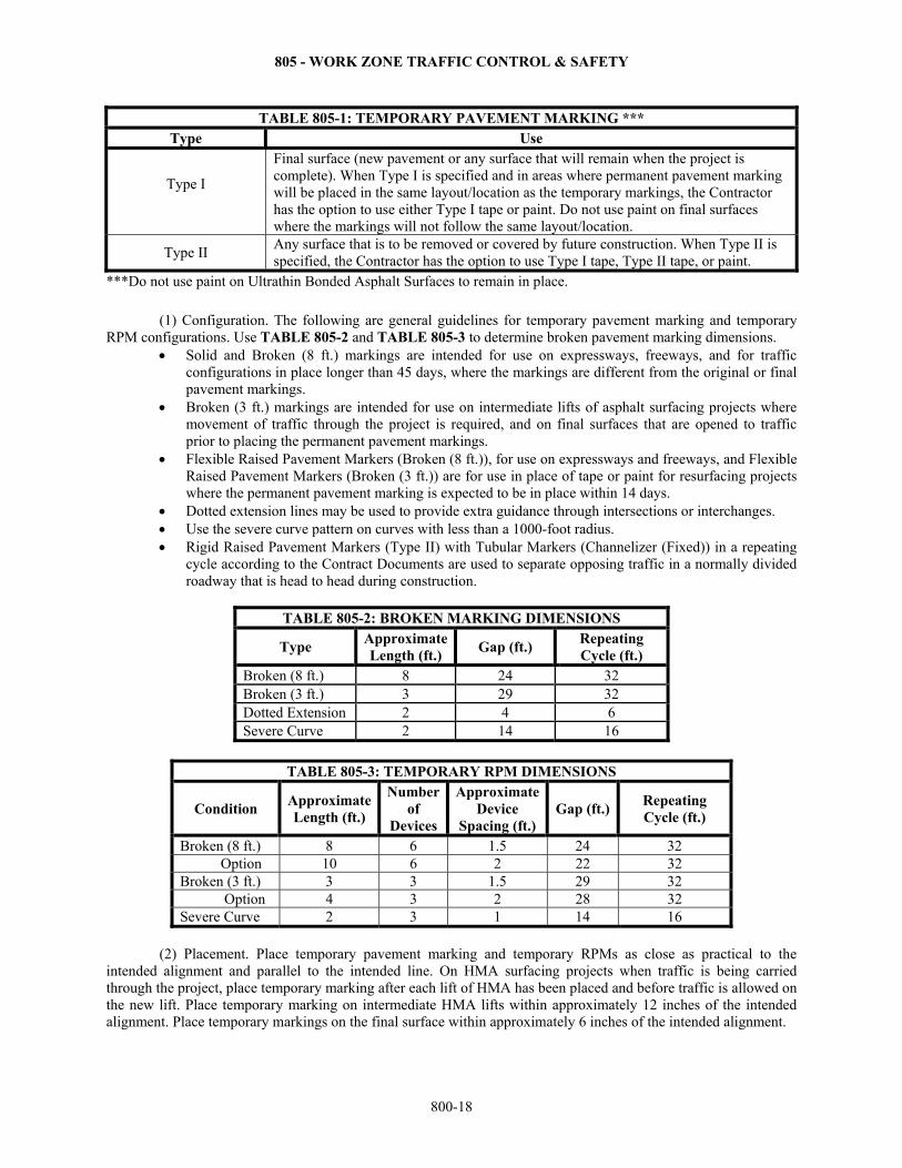
TABLE 805-1: TEMPORARY PAVEMENT MARKING *** Type Use
Type I
Final surface (new pavement or any surface that will remain when the project is complete). When Type I is specified and in areas where permanent pavement marking will be placed in the same layout/location as the temporary markings, the Contractor has the option to use either Type I tape or paint. Do not use paint on final surfaces where the markings will not follow the same layout/location.
Type II Any surface that is to be removed or covered by future construction. When Type II is specified, the Contractor has the option to use Type I tape, Type II tape, or paint.
***Do not use paint on Ultrathin Bonded Asphalt Surfaces to remain in place.
(1) Configuration. The following are general guidelines for temporary pavement marking and temporary RPM configurations. Use TABLE 805-2 and TABLE 805-3 to determine broken pavement marking dimensions.
Solid and Broken (8 ft.) markings are intended for use on expressways, freeways, and for traffic configurations in place longer than 45 days, where the markings are different from the original or final pavement markings.
Broken (3 ft.) markings are intended for use on intermediate lifts of asphalt surfacing projects where movement of traffic through the project is required, and on final surfaces that are opened to traffic prior to placing the permanent pavement markings.
Flexible Raised Pavement Markers (Broken (8 ft.)), for use on expressways and freeways, and Flexible Raised Pavement Markers (Broken (3 ft.)) are for use in place of tape or paint for resurfacing projects where the permanent pavement marking is expected to be in place within 14 days.
Dotted extension lines may be used to provide extra guidance through intersections or interchanges. Use the severe curve pattern on curves with less than a 1000-foot radius. Rigid Raised Pavement Markers (Type II) with Tubular Markers (Channelizer (Fixed)) in a repeating
cycle according to the Contract Documents are used to separate opposing traffic in a normally divided roadway that is head to head during construction.
TABLE 805-2: BROKEN MARKING DIMENSIONS
Type Approximate Length (ft.)
Gap (ft.) Repeating Cycle (ft.)
Broken (8 ft.) 8 24 32Broken (3 ft.) 3 29 32Dotted Extension 2 4 6Severe Curve 2 14 16
TABLE 805-3: TEMPORARY RPM DIMENSIONS
Condition Approximate Length (ft.)
Number of
Devices
Approximate Device
Spacing (ft.) Gap (ft.)
Repeating Cycle (ft.)
Broken (8 ft.) 8 6 1.5 24 32 Option 10 6 2 22 32 Broken (3 ft.) 3 3 1.5 29 32 Option 4 3 2 28 32 Severe Curve 2 3 1 14 16
(2) Placement. Place temporary pavement marking and temporary RPMs as close as practical to the
intended alignment and parallel to the intended line. On HMA surfacing projects when traffic is being carried through the project, place temporary marking after each lift of HMA has been placed and before traffic is allowed on the new lift. Place temporary marking on intermediate HMA lifts within approximately 12 inches of the intended alignment. Place temporary markings on the final surface within approximately 6 inches of the intended alignment.
805 - WORK ZONE TRAFFIC CONTROL & SAFETY
800-19
Place either temporary or permanent pavement markings or temporary RPMs the same day the existing markings are removed, and before opening to traffic, at the following locations: yellow skip line on undivided roads, white skip lines on multi-lane sections, white gore lines, white intersection dotted extension lines, and solid yellow ramp edge lines. Fixed tubular markers or conical delineators may be placed, and if used shall be maintained, in lieu of temporary gore lines with the Engineer’s approval. If used, space the devices at 5-foot intervals on the gore edge line. They are subsidiary to other temporary pavement marking bid items.
(3) Maintenance. Maintain all temporary pavement markings and temporary RPMs for the duration of the project and for 14 days after the work is complete. Temporary pavement marking and temporary RPMs must be in an acceptable condition and location, as described in the Contract Documents.
When temporary pavement markings or temporary RPMs are deemed deficient by the Engineer (no longer retroreflective, damaged, displaced, etc.), the Engineer will notify the Contractor in writing of areas requiring replacement.
Replacement of temporary pavement marking or temporary RPMs could be required as soon as 24 hours from notification and will be noted in the notification. Failure to replace the temporary pavement marking or temporary RPMs within the allotted time could result in a deduct of $500 per day. Deduct assessments are cumulative until deficiencies are corrected, and could be assessed even if the project is in liquidated damages for failure to complete work within the specified time.
Conditions considered for deduct include, but are not limited to the following:
Visibility less than 300 feet in daytime or nighttime conditions. Retroreflectivity less than what is specified for the specific type of pavement marking (SECTIONS
806 and 807) or temporary RPM (DIVISION 2200). Loss of material. Temporary pavement marking or temporary RPMs exceeding the following loss thresholds are subject to
the indicated daily deduct: Continuous markings cannot have deficiencies of more than 10% of the total feet of pavement
marking. Also, no more than 50 consecutive feet can be deficient nor can any deficiency be within 10 feet of another deficiency.
Intermittent markings, including but not limited to RPMs and broken markings, cannot have deficiencies of more than 10% of the total number of devices (or 10% of the broken markings required) and no more than 2 consecutive devices or markings can be deficient.
No more than 10% of any temporary marking or temporary RPMs in a curve can be deficient. (4) Temporary Pavement Marking Tape. Apply pavement marking tape according to the manufacturer’s
recommendations. If solid lane markings are required, cut through the entire width and thickness of the tape at approximately 100-foot intervals after it is applied to the pavement.
When shown in the Contract Documents, or with the Engineer’s approval, apply line masking tape to the surface to temporarily cover the existing pavement markings in widths or sizes sufficient to extend approximately 1 inch beyond the edges of the existing pavement markings.
(5) Traffic Line Paint. When paint is approved, comply with SECTION 807. (6) Flexible Raised Pavement Markers. With the Engineer’s approval, the Contractor may place flexible
RPMs in lieu of temporary skip lines and solid lines as shown in the Contract Documents. Adhere according to manufacturer’s recommendations.
When used on asphalt seals, place the flexible RPMs on the roadway prior to the sealing operation and remove the cover protecting the retroreflective material after the sealing operation.
The adhesive used shall allow the markers to be removed without damage to the roadway surface. Acquire the Engineer’s approval before using epoxy as an adhesive.
(7) Rigid Raised Pavement Markers (Type I or Type II). Install and maintain rigid RPMs at locations shown in the Contract Documents. Install and maintain according to the manufacturer’s recommendations.
j. One Way Traffic. Provide 2-way traffic and avoid 1-way traffic, where reasonable. When 1-way traffic
is required, do so according to the following: (1) Flaggers. Provide courteous, competent flaggers, able to communicate with the traveling public, to
direct traffic in a one-way traffic operation. Flaggers must be trained once every 3 years on the flagger procedures outlined in Part VI of the MUTCD and on the flagger procedures outlined in the KDOT Flagger Handbook, latest
805 - WORK ZONE TRAFFIC CONTROL & SAFETY
800-20
version. Trained flaggers are expected to behave in accordance with the previously stated flagger procedures regardless of the source of the training. Once trained, flaggers shall carry certification cards showing the flagger’s name and date of training. Copies of the KDOT Flagger Handbook are available on the KDOT website, from the Engineer or from the Bureau of Transportation Safety and Technology. In addition to being trained in flagger procedures, flaggers shall have and use the following equipment:
Stop/Slow Paddles: Equip flaggers with a minimum 18-inch wide Stop/Slow sign mounted on a rigid staff that is a minimum of 60 inches long from the end to the bottom of the sign.
Flags: In emergency situations, equip flaggers with flags that are bright red, a minimum of 24 inches square, and attached to a minimum 36-inch long staff. Flags used at night shall be retroreflective.
Apparel: Flaggers shall wear high visibility headgear and an ANSI Class II vest while on duty during daytime operations. When nighttime work is required, flaggers shall wear ANSI Class E retroreflectorized pants in addition to the high visibility headgear and ANSI Class II vest.
Illumination: When nighttime work is required, illuminate flagger stations and equipment crossings with temporary lighting. Place all lighting so that it does not create a disabling glare for approaching road users, flaggers or workers. To determine if lighting is adequate and if disabling glare exists, drive toward the flagger station from all approaches at night.
(2) Law Enforcement. The Contractor may use uniformed enforcement officers as flaggers. When used as a
flagger by the Contractor, law enforcement officers shall wear their official uniform with badge and meet the requirements for Flagger Apparel as shown in the Contract Documents.
(3) Traffic Signal Installation (Temporary). Install temporary traffic signals as shown in the Contract Documents. Place temporary signals on the shoulder when feasible, and in all cases, delineate with channelizers.
Temporary traffic signals may be used in lieu of flaggers and left unattended when each approach is visible to the other, and when approved by the Engineer. When each approach is not visible to the other, or if unattended signals are not approved by the Engineer, then the signal shall be manually operated, directly or by remote, by a Flagger trained in the operation of the signal. Temporary signals may be used at night. When signals are controlled by flaggers at night, comply with all nighttime flagger requirements. A single flagger may simultaneously operate multiple signals when:
The flagger has an unobstructed view of the signals The flagger has an unobstructed view of approaching traffic in each direction; and The flagger is accurately able to read the signals’ indicators. (4) Automated Flagger Assistance Device (AFAD). AFADs may be used in the same manner as temporary
traffic signals, except that they cannot be left unattended. Manually operate the AFAD directly or by remote, by a Flagger trained in the operation of the AFAD. AFADs may be used at night when the AFAD station is illuminated with temporary lighting and all other nighttime flagger requirements are met. A single flagger may simultaneously operate multiple AFADs when:
The flagger has an unobstructed view of the AFADs; The flagger has an unobstructed view of approaching traffic in each direction; and The flagger is accurately able to read the AFADs’ indicators. (5) Pilot Cars. A pilot car may be used to assist and lead traffic between flaggers or flagger-manned
AFADs. Maintain pilot car operations continuously, causing no delay to traffic for reasons such as refueling and breaks. The maximum time for a pilot car round trip is 15 minutes. Coordinate the work accordingly. Do not use the pilot car for other purposes.
Equip the pilot car with signs reading “Pilot Car Follow Me,” complying with Contract Documents as they pertain to sign sheeting and lettering requirements. Mount signs a minimum of 1 foot above the top of the vehicle and clearly visible from the front and rear. Display the Contractor’s company logo and contact information on pilot car vehicles.
Maintain one-way traffic and use the pilot car to restrict speeds to a maximum of 40 miles per hour in the work zone and restrict speeds in the vicinity of workers to 20 miles per hour until the last car in the pilot queue exits the vicinity of the workers.
k. Height Differential Treatment. On projects that carry traffic through construction, the following
criteria shall be considered a minimum for treatment of height differentials adjacent to traffic lanes. A height
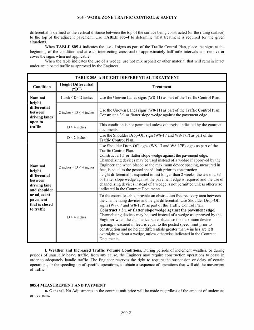
805 - WORK ZONE TRAFFIC CONTROL & SAFETY
800-21
differential is defined as the vertical distance between the top of the surface being constructed (or the riding surface) to the top of the adjacent pavement. Use TABLE 805-4 to determine what treatment is required for the given situations.
When TABLE 805-4 indicates the use of signs as part of the Traffic Control Plan, place the signs at the beginning of the condition and at each intersecting crossroad or approximately half mile intervals and remove or cover the signs when not applicable.
When the table indicates the use of a wedge, use hot mix asphalt or other material that will remain intact under anticipated traffic as approved by the Engineer.
TABLE 805-4: HEIGHT DIFFERENTIAL TREATMENT
Condition Height Differential
(“D”) Treatment
Nominal height differential between driving lanes open to traffic
1 inch < D < 2 inches Use the Uneven Lanes signs (W8-11) as part of the Traffic Control Plan.
2 inches < D < 4 inches Use the Uneven Lanes signs (W8-11) as part of the Traffic Control Plan. Construct a 3:1 or flatter slope wedge against the pavement edge.
D > 4 inches This condition is not permitted unless otherwise indicated by the contract documents.
Nominal height differential between driving lane and shoulder or adjacent pavement that is closed to traffic
D ≤ 2 inches Use the Shoulder Drop-Off sign (W8-17 and W8-17P) as part of the Traffic Control Plan.
2 inches < D < 4 inches
Use Shoulder Drop-Off signs (W8-17 and W8-17P) signs as part of the Traffic Control Plan. Construct a 1:1 or flatter slope wedge against the pavement edge. Channelizing devices may be used instead of a wedge if approved by the Engineer and when placed so the maximum device spacing, measured in feet, is equal to the posted speed limit prior to construction. height differential is expected to last longer than 2 weeks, the use of a 3:1 or flatter slope wedge against the pavement edge is required and the use of channelizing devices instead of a wedge is not permitted unless otherwise indicated in the Contract Documents.
D > 4 inches
To the extent feasible, provide an obstruction free recovery area between the channelizing devices and height differential. Use Shoulder Drop-Off signs (W8-17 and W8-17P) as part of the Traffic Control Plan. Construct a 3:1 or flatter slope wedge against the pavement edge. Channelizing devices may be used instead of a wedge as approved by the Engineer when the channelizers are placed so the maximum device spacing, measured in feet, is equal to the posted speed limit prior to construction and no height differentials greater than 4 inches are left overnight without a wedge, unless otherwise indicated in the Contract Documents.
l. Weather and Increased Traffic Volume Conditions. During periods of inclement weather, or during
periods of unusually heavy traffic, from any cause, the Engineer may require construction operations to cease in order to adequately handle traffic. The Engineer reserves the right to require the suspension or delay of certain operations, or the speeding up of specific operations, to obtain a sequence of operations that will aid the movement of traffic.
805.4 MEASUREMENT AND PAYMENT a. General. No Adjustments in the contract unit price will be made regardless of the amount of underruns
or overruns.
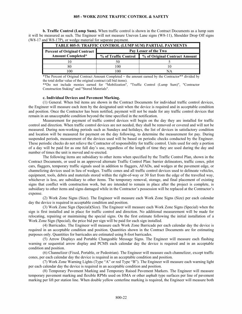
805 - WORK ZONE TRAFFIC CONTROL & SAFETY
800-22
b. Traffic Control (Lump Sum). When traffic control is shown in the Contract Documents as a lump sum it will be measured as such. The Engineer will not measure Uneven Lane signs (W8-11), Shoulder Drop Off signs (W8-17 and W8-17P), or wedge material for separate payment.
TABLE 805-5: TRAFFIC CONTROL (LUMP SUM) PARTIAL PAYMENTS
Percent of Original Contract Amount Completed*
Pay Lesser of the Two % of Traffic Control % of Original Contract Amount
10 50 5 80 100 10
100 100 NA *The Percent of Original Contract Amount Completed = the amount earned by the Contractor** divided by the total dollar value of the original contract (all bid items). **Do not include monies earned for "Mobilization", "Traffic Control (Lump Sum)", "Contractor Construction Staking" and "Stored Materials". c. Individual Devices and Pavement Marking. (1) General. When bid items are shown in the Contract Documents for individual traffic control devices,
the Engineer will measure each item by the designated unit when the device is required and in acceptable condition and position. Once the Contractor has been notified, payment will not be made for any traffic control devices that remain in an unacceptable condition beyond the time specified in the notification.
Measurement for payment of traffic control devices will begin on the day they are installed for traffic control and direction. When traffic control devices are not needed, they shall be removed or covered and will not be measured. During non-working periods such as Sundays and holidays, the list of devices in satisfactory condition and location will be measured for payment on the day following, to determine the measurement for pay. During suspended periods, measurement of the devices used will be based on periodic checks conducted by the Engineer. These periodic checks do not relieve the Contractor of responsibility for traffic control. Units used for only a portion of a day will be paid for as one full day’s use, regardless of the length of time they are used during the day and number of times the unit is moved and re-erected.
The following items are subsidiary to other items when specified by the Traffic Control Plan, shown in the Contract Documents, or used in an approved alternate Traffic Control Plan: barrier delineators, traffic cones, pilot cars, flaggers, temporary traffic signals used in addition to flaggers, AFADs, and wedges at the pavement edge, or channelizing devices used in lieu of wedges. Traffic cones and all traffic control devices used to delineate vehicles, equipment, tools, debris and materials stored within the right-of-way or 30 feet from the edge of the travelled way, whichever is less, are subsidiary to other items. The temporary removal, storage, and final placement of existing signs that conflict with construction work, but are intended to remain in place after the project is complete, is subsidiary to other items and signs damaged while in the Contractor’s possession will be replaced at the Contractor’s expense.
(2) Work Zone Signs (Size). The Engineer will measure each Work Zone Signs (Size) per each calendar day the device is required in acceptable condition and position.
(3) Work Zone Sign (Special)(Size). The Engineer will measure each Work Zone Signs (Special) when the sign is first installed and in place for traffic control and direction. No additional measurement will be made for relocating, repairing or maintaining the special signs. On the first estimate following the initial installation of a Work Zone Sign (Special), the price bid per sign will be paid for each sign installed.
(4) Barricades. The Engineer will measure each Work Zone Barricade per each calendar day the device is required in an acceptable condition and position. Quantities shown in the Contract Documents are for estimating purposes only. Quantities for barricades are estimated using 8-foot barricades.
(5) Arrow Displays and Portable Changeable Message Signs. The Engineer will measure each flashing warning or sequential arrow display and PCMS each calendar day the device is required and in an acceptable condition and position.
(6) Channelizer (Fixed, Portable, or Pedestrian). The Engineer will measure each channelizer, except traffic cones, per each calendar day the device is required in an acceptable condition and position.
(7) Work Zone Warning Lights (Type “A” or red Type “B”). The Engineer will measure each warning light per each calendar day the device is required in an acceptable condition and position.
(8) Temporary Pavement Marking and Temporary Raised Pavement Markers. The Engineer will measure temporary pavement marking and flexible RPMs used on HMA or other asphalt type surfaces per line of pavement marking per lift per station line. When double yellow centerline marking is required, the Engineer will measure both
805 - WORK ZONE TRAFFIC CONTROL & SAFETY
800-23
lines for payment. The Engineer will measure temporary pavement marking and flexible RPMs used on other types of surfacing construction per station per line. If the Contractor elects to use Type I temporary pavement marking tape in place of Type II tape, the Type I marking will be measured and paid for as Type II temporary pavement marking. Required removal of all types of temporary pavement marking is subsidiary to other items in the contract.
When necessary, removal of existing permanent pavement markings will be measured and paid for according to SECTION 808. Required removal of all types of temporary pavement marking is subsidiary to other items in the contract.
The Engineer will measure each rigid RPM. No additional measurement will be made for cleaning or replacement of markers.
Contract Deduct assessments are cumulative until deficiencies are corrected. (9) Flaggers (Set Price). When flaggers are specified in the Contract Documents or approved Traffic
Control Plan, they will not be paid for separately, but will be considered as subsidiary to other bid items. If the Contractor is allowed to use temporary traffic signals in lieu of flaggers, temporary signals will not be paid for separately, but will be considered subsidiary to other items of the contract. If the Contractor elects to use AFADs in addition to flaggers, AFADs will not be paid for separately, but will be considered subsidiary to other items of the contract. If the Engineer determines that additional flaggers are required, each additional flagger will be measured for each hour they are required.
(10) Traffic Signal Installation (Temporary). The Engineer will measure temporary traffic signals by the Lump Sum, when shown in the Contract Documents as part of the Traffic Control Plan. The Engineer will make payments as follows:
Pay 75% of the contract unit price after the traffic signals are initially installed and operational. Pay 100% after the traffic signals are no longer needed for the movement of traffic and have been removed
or stockpiled, as specified. (11) Traffic Control (Initial Set Up). If the amount bid for this item is less than 25% of the sum of amounts
bid for all traffic control items, 100% of the amount bid for this item will be paid on the first estimate following the beginning of any traffic control set up done on the project. If the bid amount for this item is 25%, or greater, than the sum of the amounts bid for all traffic control items, the amount equal to 25% of the sum of the amounts bid for all traffic control items will be paid on the first estimate following any traffic control set up done on the project. Upon completion of all work on the project, 100% of the amount bid for this item will be paid.
(12) Uneven Lane and Shoulder Drop Off Signs. When individual traffic control bid items are shown in the Contract Documents, the Engineer will measure the Uneven Lane signs (W8-11) and the Shoulder Drop Off signs (W8-17 and W8-17P) each per day. See subsection 805.4b. when traffic control is bid lump sum.
(13) Liquidated Damages. Once the Contractor is being assessed liquidated damages according to SECTION 108, no traffic control devices will be measured for payment. This does not relieve the Contractor from the responsibility for providing and maintaining all necessary traffic control on the project until it has been completed and accepted. Such traffic control will be at the Contractor’s expense.
On calendar completion date projects with interim completion dates, no traffic control devices will be measured other than those required between the interim completion date and the next beginning work period. This does not relieve the Contractor from the responsibility for maintaining all necessary traffic control on the project until it has been completed and accepted.
Contract Deducts may be assessed while the contract is in liquidated damages. d. Payment. Payment for all individual traffic control devices, "Pavement Marking (Temporary)",
"Flexible Raised Pavement Markers", "Rigid Raised Pavement Markers", "Traffic Signal Installation (Temporary)", "Traffic Control" and "Traffic Control (Initial Set Up)" at the contract unit prices is full compensation for the specified work. Payment for "Flaggers (Set Price)" at the contract set price is full compensation for the specified work.
If any deductions are assessed due to the Contractor’s failure to complete required corrective actions, the Engineer will deduct any such assessment from the date the assessment is first made until corrective action is performed using the bid item Contract Deduct.
No payment will be made while Contractor is assessed liquidated damages for failure to comply with winter shutdown period or project completion date in other Project Special Provisions included in the Contract Documents.
806 - DURABLE PAVEMENT MARKING
800-24
SECTION 806
DURABLE PAVEMENT MARKING 806.1 DESCRIPTION Prepare the pavement and apply the pavement markings as shown in the Contract Documents.
When rumble strips are to be constructed on the project, construct the centerline rumble strips before installing centerline pavement marking. BID ITEMS UNITS Pavement Marking (*) (**) (***) (*****) Linear Foot Pavement Marking Symbol (*) (White) (****) (*****) Each
*Type of Pavement Marking: Cold Plastic, Patterned Cold Plastic, Epoxy, Thermoplastic, Preformed Thermoplastic, Thermoplastic-Spray, Intersection Grade, High Durability or Multi-Component
** Color *** Width **** Type of Symbol ***** Contrast 806.2 MATERIALS Provide durable pavement marking materials that comply with DIVISION 2200. 806.3 CONSTRUCTION REQUIREMENTS a. General. (1) Equipment. Use equipment designed for the preparation and application of the appropriate type of pavement marking material. (2) Contractor’s Personnel. Provide a minimum of 1 employee on the project holding an American Traffic Safety Services Association (ATSSA) pavement marking certification and experienced in the application of the appropriate type of pavement marking material. (3) Pavement Marking Contractors. Provide a letter of certification from the pavement marking manufacturer indicating the Contractor’s qualifications to install their product.
(4) Test Strip. Before beginning pavement marking operations, at a location approved by the Engineer complete a 300-foot test section for epoxy, thermoplastic, sprayed thermoplastic and multi-component pavement markings that meet the requirements of this specification. The Engineer will inspect the test strip 24 hours after it has been placed. Do not begin pavement marking operations, until the Engineer approves the test strip.
(5) Surface Preparation. On existing pavements, remove the existing permanent, pavement markings (removed and paid for under SECTION 808) and according to the recommendations of the manufacturer of the new pavement markings. Remove temporary pavement markings, if any, the same day the durable pavement markings are applied. Removal of temporary pavement marking is subsidiary to temporary pavement marking bid items. Remove loose particles, dirt, tar, grease, residue of prior pavement markings and other deleterious material from the pavement surfaces. (6) Alignment. Lay out the pavement marking as detailed in the Contract Documents. If the Contract Documents do not provide details, submit to the Engineer for approval, a layout plan for the pavement markings that complies to the MUTCD. Locate longitudinal pavement marking stripes a minimum of 2 inches and a maximum of 8 inches from longitudinal joints. Provide adequate guide marks (approximately 2 inches by 12 inches at approximately 30 to 50-foot intervals) for the application of the pavement markings. When applying pavement markings at locations with newly constructed rumble strips, use the same guide marks that were used for milling the rumble strips, or when approved by the Engineer, establish a new guide mark, if the guide mark used with the rumble strips is not visible enough to follow.
(7) Pavement Marking Width. Apply the pavement markings at the specified plan width or a maximum of ¼ inch above the specified plan width. See TABLE 806-3 for minimum pavement marking widths.
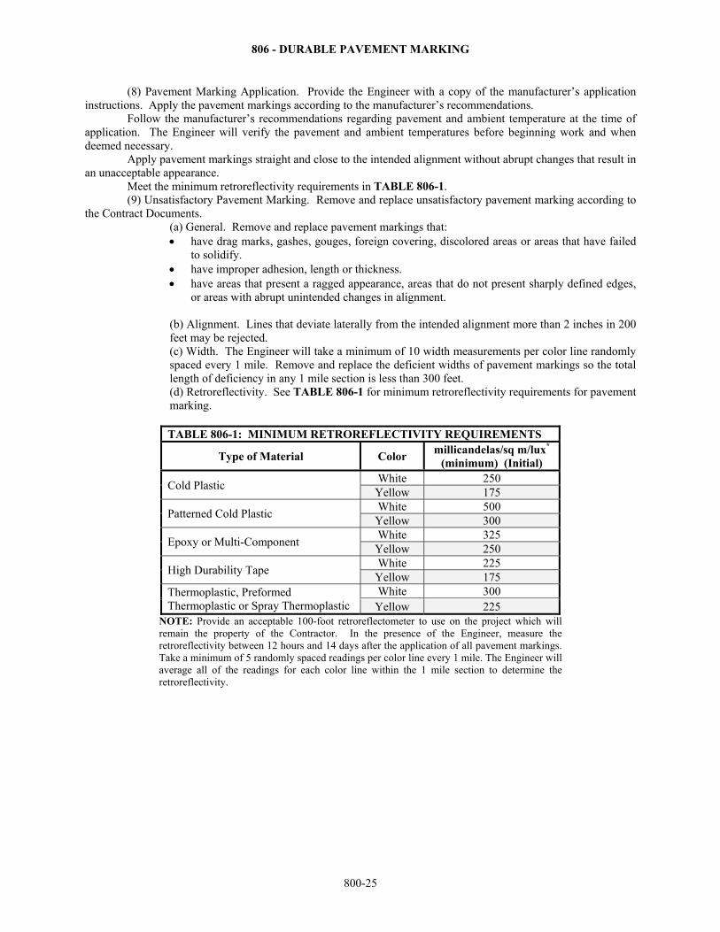
806 - DURABLE PAVEMENT MARKING
800-25
(8) Pavement Marking Application. Provide the Engineer with a copy of the manufacturer’s application instructions. Apply the pavement markings according to the manufacturer’s recommendations. Follow the manufacturer’s recommendations regarding pavement and ambient temperature at the time of application. The Engineer will verify the pavement and ambient temperatures before beginning work and when deemed necessary.
Apply pavement markings straight and close to the intended alignment without abrupt changes that result in an unacceptable appearance.
Meet the minimum retroreflectivity requirements in TABLE 806-1. (9) Unsatisfactory Pavement Marking. Remove and replace unsatisfactory pavement marking according to the Contract Documents.
(a) General. Remove and replace pavement markings that: have drag marks, gashes, gouges, foreign covering, discolored areas or areas that have failed
to solidify. have improper adhesion, length or thickness. have areas that present a ragged appearance, areas that do not present sharply defined edges,
or areas with abrupt unintended changes in alignment. (b) Alignment. Lines that deviate laterally from the intended alignment more than 2 inches in 200 feet may be rejected. (c) Width. The Engineer will take a minimum of 10 width measurements per color line randomly spaced every 1 mile. Remove and replace the deficient widths of pavement markings so the total length of deficiency in any 1 mile section is less than 300 feet. (d) Retroreflectivity. See TABLE 806-1 for minimum retroreflectivity requirements for pavement marking.
TABLE 806-1: MINIMUM RETROREFLECTIVITY REQUIREMENTS
Type of Material Color millicandelas/sq m/lux*
(minimum) (Initial)
Cold Plastic White 250
Yellow 175
Patterned Cold Plastic White 500
Yellow 300
Epoxy or Multi-Component White 325
Yellow 250
High Durability Tape White 225
Yellow 175 Thermoplastic, Preformed Thermoplastic or Spray Thermoplastic
White 300 Yellow 225
NOTE: Provide an acceptable 100-foot retroreflectometer to use on the project which will remain the property of the Contractor. In the presence of the Engineer, measure the retroreflectivity between 12 hours and 14 days after the application of all pavement markings. Take a minimum of 5 randomly spaced readings per color line every 1 mile. The Engineer will average all of the readings for each color line within the 1 mile section to determine the retroreflectivity.
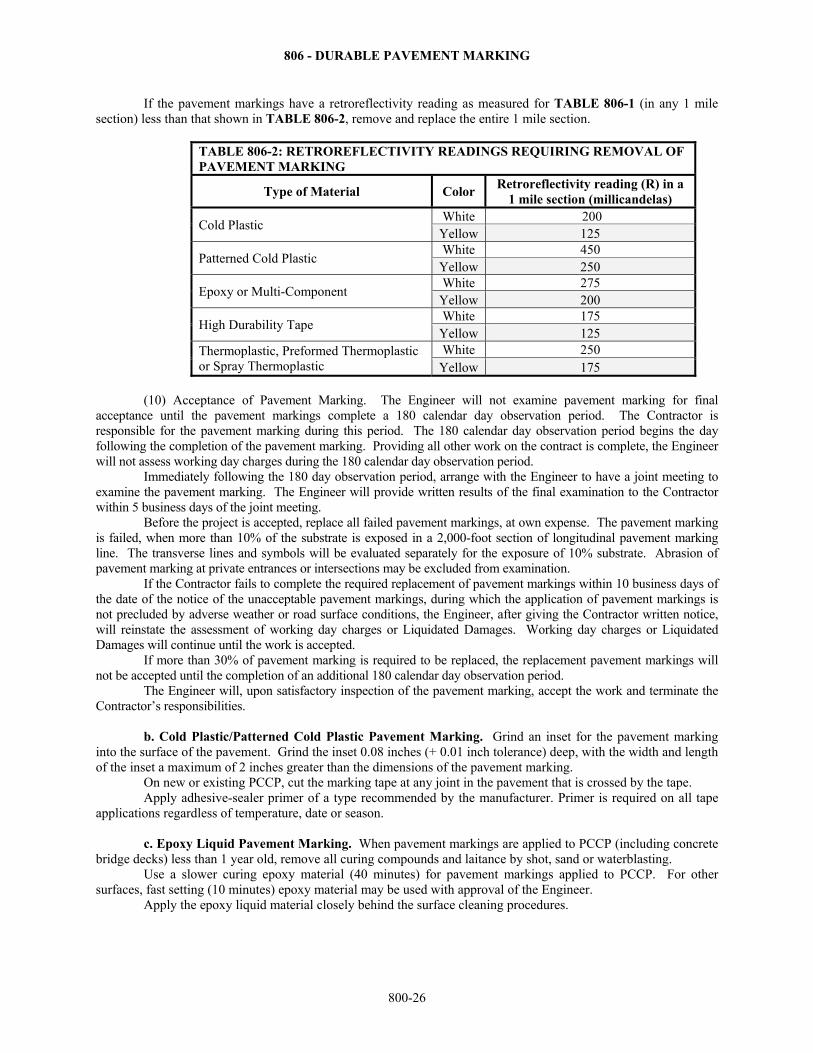
806 - DURABLE PAVEMENT MARKING
800-26
If the pavement markings have a retroreflectivity reading as measured for TABLE 806-1 (in any 1 mile section) less than that shown in TABLE 806-2, remove and replace the entire 1 mile section.
TABLE 806-2: RETROREFLECTIVITY READINGS REQUIRING REMOVAL OF PAVEMENT MARKING
Type of Material Color Retroreflectivity reading (R) in a
1 mile section (millicandelas)
Cold Plastic White 200
Yellow 125
Patterned Cold Plastic White 450
Yellow 250
Epoxy or Multi-Component White 275
Yellow 200
High Durability Tape White 175
Yellow 125 Thermoplastic, Preformed Thermoplastic or Spray Thermoplastic
White 250 Yellow 175
(10) Acceptance of Pavement Marking. The Engineer will not examine pavement marking for final
acceptance until the pavement markings complete a 180 calendar day observation period. The Contractor is responsible for the pavement marking during this period. The 180 calendar day observation period begins the day following the completion of the pavement marking. Providing all other work on the contract is complete, the Engineer will not assess working day charges during the 180 calendar day observation period.
Immediately following the 180 day observation period, arrange with the Engineer to have a joint meeting to examine the pavement marking. The Engineer will provide written results of the final examination to the Contractor within 5 business days of the joint meeting.
Before the project is accepted, replace all failed pavement markings, at own expense. The pavement marking is failed, when more than 10% of the substrate is exposed in a 2,000-foot section of longitudinal pavement marking line. The transverse lines and symbols will be evaluated separately for the exposure of 10% substrate. Abrasion of pavement marking at private entrances or intersections may be excluded from examination. If the Contractor fails to complete the required replacement of pavement markings within 10 business days of the date of the notice of the unacceptable pavement markings, during which the application of pavement markings is not precluded by adverse weather or road surface conditions, the Engineer, after giving the Contractor written notice, will reinstate the assessment of working day charges or Liquidated Damages. Working day charges or Liquidated Damages will continue until the work is accepted. If more than 30% of pavement marking is required to be replaced, the replacement pavement markings will not be accepted until the completion of an additional 180 calendar day observation period. The Engineer will, upon satisfactory inspection of the pavement marking, accept the work and terminate the Contractor’s responsibilities. b. Cold Plastic/Patterned Cold Plastic Pavement Marking. Grind an inset for the pavement marking into the surface of the pavement. Grind the inset 0.08 inches (+ 0.01 inch tolerance) deep, with the width and length of the inset a maximum of 2 inches greater than the dimensions of the pavement marking. On new or existing PCCP, cut the marking tape at any joint in the pavement that is crossed by the tape. Apply adhesive-sealer primer of a type recommended by the manufacturer. Primer is required on all tape applications regardless of temperature, date or season. c. Epoxy Liquid Pavement Marking. When pavement markings are applied to PCCP (including concrete bridge decks) less than 1 year old, remove all curing compounds and laitance by shot, sand or waterblasting. Use a slower curing epoxy material (40 minutes) for pavement markings applied to PCCP. For other surfaces, fast setting (10 minutes) epoxy material may be used with approval of the Engineer. Apply the epoxy liquid material closely behind the surface cleaning procedures.
806 - DURABLE PAVEMENT MARKING
800-27
Before mixing the components of the pavement marking material, heat the individual components to the temperature ranges recommended by the manufacturer of the material. Do not exceed the maximum recommended temperature at any time. Apply the epoxy liquid pavement marking material at a thickness of 20-25 mils on all pavement. Immediately apply all glass beads (double drop system or blended bead) to the epoxy liquid pavement marking at the glass bead gradation and bead drop rate recommended by the manufacturer to obtain the required level of retroreflectivity. d. Multi-Component Liquid Pavement Marking. When pavement markings are applied to PCCP (including concrete bridge decks) less than 1 year old, remove all curing compounds and laitance by shot, sand or waterblasting. For intersection grade multi-component, grind the inset 15 mil (+10 mil tolerance) deep, with the width and length of the inset a maximum of 2 inches greater than the dimensions of the pavement marking on concrete surfaces. Multi-component liquid pavement marking will only be allowed for use on concrete pavement on a pre-qualified basis. Apply the multi-component liquid material closely behind the surface cleaning procedures. Before mixing the components of the pavement marking material, heat the individual components to the temperature ranges recommended by the manufacturer of the material. Do not exceed the maximum recommended temperature at any time. Apply the multi-component liquid pavement marking material at the thickness of 20-25 mils on all pavement. Immediately apply the glass beads (double drop system or blended drop) to the multi-component liquid pavement marking at the glass bead gradation and bead drop rate recommended by the manufacturer to obtain the required level of retroreflectivity.
e. Intersection Grade Pavement Marking. (1) Multi-Component. Follow subsection 806.3d.
(2) High Durability Tape. Grind an inset for the pavement marking into the surface of the pavement. Grind the inset 80 mil (+10 mil tolerance) deep with the width and length of the inset a maximum of 2 inches greater than the dimensions of the pavement marking. Apply adhesive-sealer primer of a type recommended by the manufacturer. Primer is required on all tape applications regardless of temperature, date or season.
On new or existing PCCP, cut the marking tape on either side of any joint in the pavement that is crossed by the tape.
(3) Preformed Thermoplastic. Grind the inset 40 mil (+ 20 mil tolerance) deep with the width and length of the inset a maximum of 2 inches greater than the dimensions of the pavement marking on concrete surfaces. Use a heating device recommended by the material manufacturer to fuse the preformed thermoplastic to the pavement. Apply adhesive-sealer primer of a type recommended by the manufacturer. Primer is required on all preformed applications on concrete regardless of temperature, date or season.
Apply the pavement markings as recommended by the manufacturer. f. All Thermoplastic Pavement Marking. The Engineer will verify the thickness of the thermoplastic pavement marking. Thickness will be checked by placing metal plates or other suitable material of known thickness in a 3-foot section along the path of application at 2 to 3 locations. After the application of the thermoplastic material, the samples will be cut free. The material thickness will be measured using either a micrometer or vernier calipers (with proper correction for the metal plate). The thickness recorded for the locations within the 3-foot section will be averaged. Initially, thickness determinations will be made every ⅓ mile for each color and each stripe width. Once a pattern of compliance is established, the Engineer may reduce the frequency of thickness verification to once each 1 mile section. Failure of a section will require testing to return to the initial frequency until compliance may be re-established. The location of the 3-foot sample segment within the sample section will be selected at random. The Contractor may provide other devices for gauging thickness to the Engineer for approval. Apply thermoplastic pavement markings between April 15 and October 15. If the manufacturer’s recommendations allow, the Engineer may waive the date restrictions. The Engineer will notify the Contractor in writing of any allowed variance. (1) Thermoplastic Pavement Marking. The required thickness for longitudinal markings is a minimum of 90 mil at the edges, and a maximum of 125 mil at the center of the stripe. The required thickness for transverse markings and symbols is a minimum of 90 mil at the edges, and a maximum of 140 mil at the center.
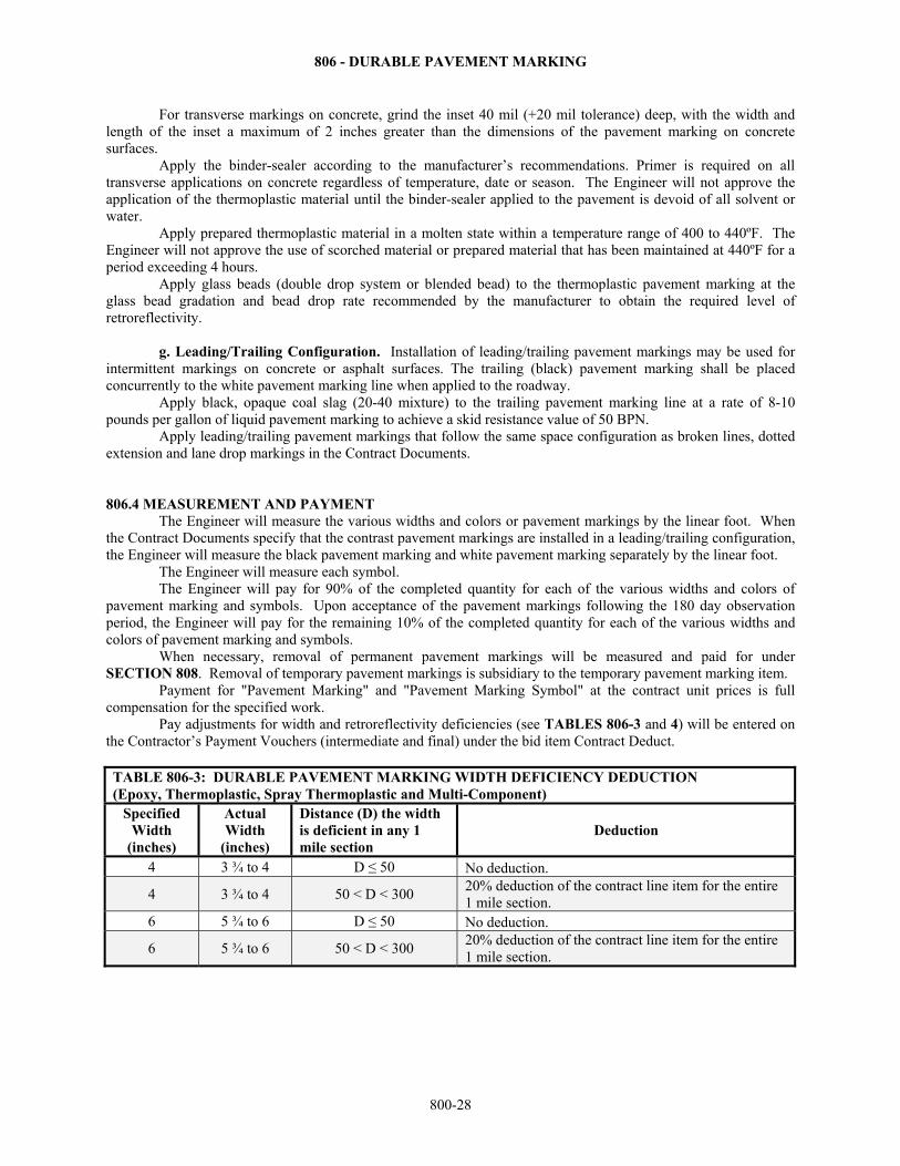
806 - DURABLE PAVEMENT MARKING
800-28
For transverse markings on concrete, grind the inset 40 mil (+20 mil tolerance) deep, with the width and length of the inset a maximum of 2 inches greater than the dimensions of the pavement marking on concrete surfaces.
Apply the binder-sealer according to the manufacturer’s recommendations. Primer is required on all transverse applications on concrete regardless of temperature, date or season. The Engineer will not approve the application of the thermoplastic material until the binder-sealer applied to the pavement is devoid of all solvent or water. Apply prepared thermoplastic material in a molten state within a temperature range of 400 to 440ºF. The Engineer will not approve the use of scorched material or prepared material that has been maintained at 440ºF for a period exceeding 4 hours. Apply glass beads (double drop system or blended bead) to the thermoplastic pavement marking at the glass bead gradation and bead drop rate recommended by the manufacturer to obtain the required level of retroreflectivity.
g. Leading/Trailing Configuration. Installation of leading/trailing pavement markings may be used for
intermittent markings on concrete or asphalt surfaces. The trailing (black) pavement marking shall be placed concurrently to the white pavement marking line when applied to the roadway.
Apply black, opaque coal slag (20-40 mixture) to the trailing pavement marking line at a rate of 8-10 pounds per gallon of liquid pavement marking to achieve a skid resistance value of 50 BPN.
Apply leading/trailing pavement markings that follow the same space configuration as broken lines, dotted extension and lane drop markings in the Contract Documents.
806.4 MEASUREMENT AND PAYMENT The Engineer will measure the various widths and colors or pavement markings by the linear foot. When the Contract Documents specify that the contrast pavement markings are installed in a leading/trailing configuration, the Engineer will measure the black pavement marking and white pavement marking separately by the linear foot.
The Engineer will measure each symbol. The Engineer will pay for 90% of the completed quantity for each of the various widths and colors of pavement marking and symbols. Upon acceptance of the pavement markings following the 180 day observation period, the Engineer will pay for the remaining 10% of the completed quantity for each of the various widths and colors of pavement marking and symbols.
When necessary, removal of permanent pavement markings will be measured and paid for under SECTION 808. Removal of temporary pavement markings is subsidiary to the temporary pavement marking item.
Payment for "Pavement Marking" and "Pavement Marking Symbol" at the contract unit prices is full compensation for the specified work.
Pay adjustments for width and retroreflectivity deficiencies (see TABLES 806-3 and 4) will be entered on the Contractor’s Payment Vouchers (intermediate and final) under the bid item Contract Deduct.
TABLE 806-3: DURABLE PAVEMENT MARKING WIDTH DEFICIENCY DEDUCTION (Epoxy, Thermoplastic, Spray Thermoplastic and Multi-Component)
Specified Width
(inches)
Actual Width
(inches)
Distance (D) the width is deficient in any 1 mile section
Deduction
4 3 ¾ to 4 D ≤ 50 No deduction.
4 3 ¾ to 4 50 < D < 300 20% deduction of the contract line item for the entire 1 mile section.
6 5 ¾ to 6 D ≤ 50 No deduction.
6 5 ¾ to 6 50 < D < 300 20% deduction of the contract line item for the entire 1 mile section.
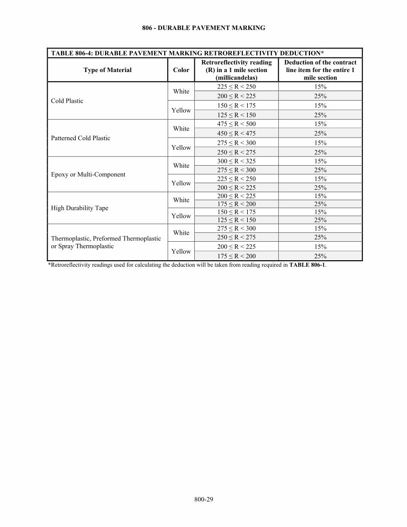
806 - DURABLE PAVEMENT MARKING
800-29
TABLE 806-4: DURABLE PAVEMENT MARKING RETROREFLECTIVITY DEDUCTION*
Type of Material Color Retroreflectivity reading
(R) in a 1 mile section (millicandelas)
Deduction of the contract line item for the entire 1
mile section
Cold Plastic
White 225 ≤ R < 250 15%
200 ≤ R < 225 25%
Yellow 150 ≤ R < 175 15%
125 ≤ R < 150 25%
Patterned Cold Plastic
White 475 ≤ R < 500 15%
450 ≤ R < 475 25%
Yellow 275 ≤ R < 300 15%
250 ≤ R < 275 25%
Epoxy or Multi-Component White
300 ≤ R < 325 15% 275 ≤ R < 300 25%
Yellow 225 ≤ R < 250 15% 200 ≤ R < 225 25%
High Durability Tape White
200 ≤ R < 225 15% 175 ≤ R < 200 25%
Yellow 150 ≤ R < 175 15% 125 ≤ R < 150 25%
Thermoplastic, Preformed Thermoplastic or Spray Thermoplastic
White 275 ≤ R < 300 15% 250 ≤ R < 275 25%
Yellow 200 ≤ R < 225 15%
175 ≤ R < 200 25% *Retroreflectivity readings used for calculating the deduction will be taken from reading required in TABLE 806-1.

807 - PAINTED PAVEMENT MARKING
800-30
SECTION 807
PAINTED PAVEMENT MARKING
807.1 DESCRIPTION Apply pavement markings as shown in the Contract Documents. BID ITEMS UNITS Pavement Marking (Paint) (*) (**) Linear Foot Pavement Marking Symbol (Paint) (White) (***) Each * Color ** Width *** Type of Symbol 807.2 MATERIALS Provide paint that complies with SECTION 2200. 807.3 CONSTRUCTION REQUIREMENTS a. Equipment. Use self-propelled or truck-mounted equipment designed for the purpose of applying painted pavement markings of the type, width and thickness required. Hand application or towing of the equipment will be allowed for smaller areas as approved by the Engineer. Equip the machine with an adjustable guide-on to obtain proper placement of the line. b. Contractor’s Personnel. Provide a minimum of 1 employee on the project holding an American Traffic Safety Services Association (ATSSA) pavement marking certification and experienced in the application of the appropriate type of pavement marking material. c. Surface Preparation. On existing pavements, remove the existing pavement markings according to DIVISION 808 and the recommendations of the manufacturer of the new painted pavement markings. Remove temporary pavement markings, if any, the same day the painted pavement markings are applied. Remove loose particles, dirt, tar, grease, residue of prior pavement markings and other deleterious material from the pavement surfaces as a result of surface preparation. d. Alignment. Lay out the pavement marking as detailed in the Contract Documents. If the Contract Documents do not provide details, submit a layout plan for the pavement markings to the Engineer for approval. Locate longitudinal pavement marking stripes a minimum of 2 inches and a maximum of 8 inches from longitudinal joints. Provide adequate guide marks (approximately 2 inches by 1 foot at approximately 50-foot intervals) for the application of the pavement markings. e. Pavement Marking Application. Provide the Engineer with a copy of the manufacturer’s application instructions. Apply paint according to the manufacturer’s recommendations.
Apply paint at a wet film thickness of 18 mils at an approximate rate of 3.8 gallons per 1,000-foot for 4-inch solid line, and 0.95 gallons per 1,000-foot for 4-inch broken line. For other widths of marking, increase the amount of paint proportionally. Apply glass beads to the painted line at a rate of 12 pounds of glass beads for each gallon of paint. Use an automatic bead dispenser attached to the striping machine in such a manner that the beads are dispensed almost instantaneously upon the line as it is being installed. Equip the glass bead dispenser with an automatic cut-off control synchronized with the cut-off of the paint. Keep traffic from crossing the newly applied lines by coning off the lines until the lines are dry to no-pick-up. The Contractor may reduce or eliminate the need for this by using fast dry paints and approved traffic control.
Do not apply the paint when the air temperature is below 40ºF, upon damp or frosted surfaces, or when, in the opinion of the Engineer, conditions are not satisfactory for the work.
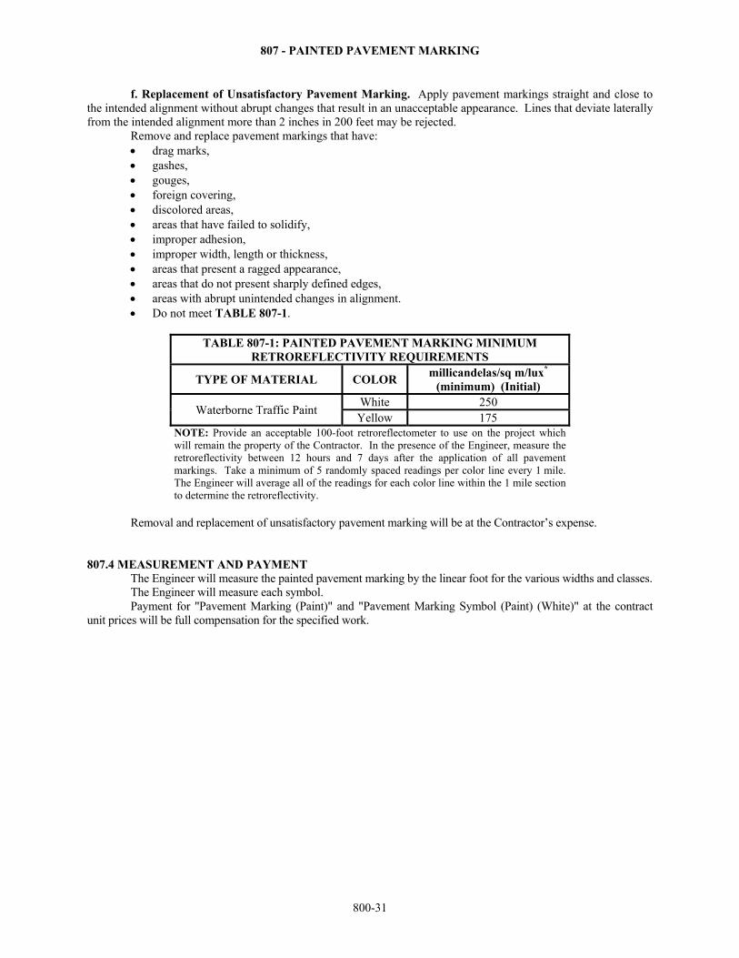
807 - PAINTED PAVEMENT MARKING
800-31
f. Replacement of Unsatisfactory Pavement Marking. Apply pavement markings straight and close to the intended alignment without abrupt changes that result in an unacceptable appearance. Lines that deviate laterally from the intended alignment more than 2 inches in 200 feet may be rejected. Remove and replace pavement markings that have:
drag marks, gashes, gouges, foreign covering, discolored areas, areas that have failed to solidify, improper adhesion, improper width, length or thickness, areas that present a ragged appearance, areas that do not present sharply defined edges, areas with abrupt unintended changes in alignment. Do not meet TABLE 807-1.
TABLE 807-1: PAINTED PAVEMENT MARKING MINIMUM
RETROREFLECTIVITY REQUIREMENTS
TYPE OF MATERIAL COLOR millicandelas/sq m/lux*
(minimum) (Initial)
Waterborne Traffic Paint White 250
Yellow 175 NOTE: Provide an acceptable 100-foot retroreflectometer to use on the project which will remain the property of the Contractor. In the presence of the Engineer, measure the retroreflectivity between 12 hours and 7 days after the application of all pavement markings. Take a minimum of 5 randomly spaced readings per color line every 1 mile. The Engineer will average all of the readings for each color line within the 1 mile section to determine the retroreflectivity.
Removal and replacement of unsatisfactory pavement marking will be at the Contractor’s expense.
807.4 MEASUREMENT AND PAYMENT The Engineer will measure the painted pavement marking by the linear foot for the various widths and classes.
The Engineer will measure each symbol. Payment for "Pavement Marking (Paint)" and "Pavement Marking Symbol (Paint) (White)" at the contract unit prices will be full compensation for the specified work.
808 - REMOVAL OF EXISTING PAVEMENT MARKINGS
800-32
SECTION 808
REMOVAL OF EXISTING PAVEMENT MARKINGS 808.1 DESCRIPTION Remove the existing pavement markings and symbols as shown in the Contract Documents. BID ITEMS UNITS Pavement Marking Removal Linear Foot Pavement Marking Removal (Plowable Raised Marker) Each 808.2 MATERIALS - None specified. 808.3 CONSTRUCTION REQUIREMENTS a. Removal of Existing Stripes and Symbols. Completely remove the existing pavement markings and symbols without damaging the asphalt or concrete pavement surface or longitudinal and transverse joints. Waterblasting will only be allowed for removal of markings on concrete surfaces. As the work progresses, remove all material deposited on the pavement as a result of the removal operations. When blast cleaning within 10 feet of the traveling public, continuously remove all residue and dust. When replacement of the removed existing markings is a part of the Contract Documents, follow the manufacturer’s requirements for the new pavement markings as to the method of removal of the existing markings, or surface preparation requirements. b. Removal of Plowable Raised Markers. If the plowable raised markers are to be reinstalled, remove them without damaging. All damaged plowable raised markers will be replaced at the Contractor’s expense. c. Repair. Use methods approved by the Engineer to repair all pavement damaged during the pavement marking removal operations. 808.4 MEASUREMENT AND PAYMENT The Engineer will measure the removal of each skip and solid line of existing pavement marking by the linear foot. NOTE: Removal of temporary pavement marking is subsidiary to the temporary pavement marking bid item.
The Engineer will measure each plowable raised marker removed. The Engineer will not measure removal of existing pavement marking symbols for payment.
Payment for "Pavement Marking Removal" and "Pavement Marking Removal (Plowable Raised Marker)" at the contract unit prices is full compensation for the specified work.
809 - CONCRETE SAFETY BARRIER
800-33
SECTION 809
CONCRETE SAFETY BARRIER 809.1 DESCRIPTION Construct permanent cast-in-place concrete safety barrier according to the Contract Documents. Place and remove temporary precast concrete safety barrier according to Contract Documents. BID ITEMS UNITS Concrete Safety Barrier (*) Linear Foot Concrete Safety Barrier (*) (Temporary) Linear Foot Concrete Safety Barrier (*) (Temporary - Installation Only) Linear Foot Concrete Safety Barrier (*) (Temporary - Relocate) Linear Foot *Type 809.2 MATERIALS a. Permanent Cast-in-Place Concrete Safety Barrier. Provide materials that comply with the Contract Documents and DIVISIONS 1000 - 2500. The Engineer will visually inspect the completed installation before making final acceptance. b. Temporary Precast Concrete Safety Barrier. Provide certification (prepared by the manufacturer or Contractor) that the temporary precast concrete safety barrier complies with the requirements on the Contract Documents. Provide either new or used, temporary precast concrete safety barrier. The Engineer will accept, either new or used, temporary precast concrete safety barrier upon acceptance of the provided certification, and visual inspection of the delivered and installed temporary precast concrete safety barrier on the project. c. Median Filler Material. Provide SB-3 for median filler material that complies with DIVISION 1100. 809.3 CONSTRUCTION REQUIREMENTS a. Permanent Cast-in-Place Concrete Safety Barrier. Construct the cast-in-place concrete safety barrier as shown in the Contract Documents and according to DIVISION 700. Place median filler material as indicated in the Contract Documents. b. Temporary Precast Concrete Safety Barrier. Install and remove the precast concrete safety barrier as required. Do not use temporary precast concrete safety barrier that is damaged or deteriorated. Erect the temporary precast concrete safety barrier as shown in the Contract Documents. The temporary precast concrete safety barrier will remain the property of the Contractor, unless shown otherwise in the Contract Documents. If the Contract Documents require installation only, transport from the designated stockpile, install and return the temporary precast concrete safety barrier to the designated location. Relocate the temporary precast concrete safety barrier as shown in the Contract Documents, or as directed by the Engineer. Remove and replace all sections of temporary precast concrete safety barrier damaged during or after placement. Remove, clean or replace temporary precast concrete safety barrier (including barrier delineators) that has deteriorated to the point of being non-effective. 809.4 MEASUREMENT AND PAYMENT a. Permanent Cast-in-Place Concrete Safety Barrier. The Engineer will measure cast-in-place concrete safety barrier by the linear foot along the centerline of the barrier. Payment for "Concrete Safety Barrier (*)" at the contract unit prices is full compensation for the specified work. Median filler material is subsidiary to other items in the contract.
809 - CONCRETE SAFETY BARRIER
800-34
b. Temporary Precast Concrete Safety Barrier. The Engineer will measure the precast concrete safety barrier by the linear foot (number of sections times the nominal section length). A precast concrete safety barrier transition section (regardless of actual length) will be measured as a nominal section length of temporary precast concrete safety barrier.
The quantity of precast concrete safety barrier measured for payment is the maximum quantity required on the project at any one time, plus any replacement sections measured for payment, and is paid for as Concrete Safety Barrier (*) (Temporary). Each section of temporary precast concrete safety barrier will be measured for payment when put in use on the project.
Sections of temporary precast concrete safety barrier used to replace sections damaged by traffic while in use will be measured for payment and paid as Concrete Safety Barrier (*) (Temporary-Installation Only) when put in use on the project. When provided by the Contractor, sections of temporary precast concrete safety barrier used to replace deteriorated sections or sections damaged through negligence of the Contractor are not measured for payment. When stage construction requires that the precast concrete safety barrier be moved from its initial position to an alternate position, the Engineer will measure the relocated barrier by the linear foot (number of sections times the nominal section length). The barrier will be measured for payment in each relocated position the barrier is placed and is paid as Concrete Safety Barrier (*) (Temporary-Relocate). If the stage construction requires that the barrier be removed from the project to a storage location, and returned to the project during a subsequent construction stage, each movement of the barrier will be considered a relocation. Removal of the precast concrete safety barrier, when no longer required on the project, is not measured for separate payment. Payment for "Concrete Safety Barrier (*) (Temporary)", "Concrete Safety Barrier (*) (Temporary-Installation Only)", and "Concrete Safety Barrier (*) (Temporary-Relocate)" at the contract unit prices is full compensation for the specified work. The quantities shown in the Contract Documents for the various items of temporary precast concrete safety barrier are estimated. The contract unit prices will not be adjusted, regardless of overruns or underruns.
810 - INERTIAL BARRIER SYSTEM
800-35
SECTION 810
INERTIAL BARRIER SYSTEM 810.1 DESCRIPTION Install and relocate inertial barrier systems as shown in the Contract Documents. Stockpile the replacement modules at the project site. BID ITEMS UNITS Inertial Barrier System Each Replacement Modules (*) Each *Series 810.2 MATERIALS Provide aggregate for underdrains, UD-1 or fine aggregate for concrete, or FA-A that complies with DIVISION 1100. Provide inertial barrier systems and replacement modules that comply with DIVISION 1700. Provide commercially available rock salt. The Engineer will accept the rock salt based on visual inspection at the point of usage.
Impact attenuators prequalified under DIVISION 1700 may be substituted for inertial barrier systems with approval of the Engineer. 810.3 CONSTRUCTION REQUIREMENTS Provide the Engineer with the manufacturer’s product data sheets for the inertial barrier system. Install the inertial barrier system according to the manufacturer’s recommendations. At the beginning of each project and in the presence of the Engineer, fill the inertial barrier system modules with a mixture of 95% aggregate and 5% rock salt by weight. Use aggregate with a moisture content of 3% or less by weight, determined according to DIVISION 2500. Fill each of the modules with any of the specified mixture of aggregates and rock salt. Do not mix the types of aggregates within a module. When shown in the Contract Documents relocate the inertial barrier system. Install replacement modules of the inertial barrier system when damaged by traffic. Unless otherwise noted in the Contract Documents, the inertial barrier system and replacement modules are the property of the Contractor upon completion of the project. 810.4 MEASUREMENT AND PAYMENT The Engineer will measure each inertial barrier system. Each unit will be measured only once, even if the unit is relocated on the project. The Engineer will measure each replacement module used on the project. The quantity of replacement modules stockpiled on the project site, but not used on the project, will not be measured for payment. Payment for each for "Inertial Barrier System" and "Replacement Modules" at the contract unit prices is full compensation for the specified work.
811 – IMPACT ATTENUATOR
800-36
SECTION 811
IMPACT ATTENUATOR 811.1 DESCRIPTION
a. Permanent Impact Attenuator. Install the impact attenuation devices at the locations designated in the Contract Documents.
b. Impact Attenuator (Temporary). When specified as part of project traffic control, install and relocate
the temporary impact attenuation devices at the locations designated in the Contract Documents. Stockpile the required replacement modules for each type of temporary system used on the project at the
project site. Install replacement modules when damaged.
BID ITEMS UNITS Impact Attenuator (*) Each *Type (TL-2, TL-3 or Severe Duty)
Impact Attenuator (Temporary) Each
Replacement Modules Each 811.2 MATERIALS a. Permanent Impact Attenuator. Provide the type and model of impact attenuator designated in the Contract Documents or an approved equivalent. The Bureau of Construction and Materials will maintain a list of approved impact attenuators.
The Engineer will accept the impact attenuators based on the brand name and model, and visual inspection for condition at the point of usage.
b. Impact Attenuator (Temporary). Provide the type and model of impact attenuator designated in the
Contract Documents or an approved equivalent. An inertial barrier system is not an approved equivalent. The Bureau of Construction and Materials will maintain a list of approved impact attenuators.
The Engineer will accept the impact attenuators based on the brand name and model, and visual inspection for condition at the point of usage.
c. Materials for Base. Provide concrete and reinforcing steel that comply with SECTIONS 401, 402,
1102 and DIVISON 1600. 811.3 CONSTRUCTION REQUIREMENTS a. Permanent Impact Attenuator. Construct the reinforced concrete base according to the applicable portions of DIVISION 700 and as shown in the Contract Documents. Provide the Engineer with a printed copy of the manufacturer’s recommendations for installation of the impact attenuator. Install the impact attenuation device according to the manufacturer’s recommendations. b. Impact Attenuator (Temporary). Construct the reinforced concrete base according to the applicable portions of DIVISION 700 and as shown in the Contract Documents. Provide the Engineer with a printed copy of the manufacturer’s recommendations for installation of the impact attenuator. Install the impact attenuation device according to the manufacturer’s recommendations.
When shown in the Contract Documents, relocate the temporary impact attenuator. Install replacement modules of the temporary impact attenuator when damaged. Unless otherwise noted in the Contract Documents, the temporary impact attenuator and replacement modules are the property of the Contractor upon completion of the project.
811 – IMPACT ATTENUATOR
800-37
811.4 MEASUREMENT AND PAYMENT a. Permanent Impact Attenuator. The Engineer will measure each impact attenuator.
Payment for the "Impact Attenuator (*) at the contract unit price is full compensation for the specified work.
b. Impact Attenuator (Temporary). When installed as part of project traffic control, the Engineer will measure each temporary impact attenuator. Each unit will be measured only once, even if the unit is relocated on the project.
The Engineer will measure each replacement module used on the project. The quantity of replacement modules stockpiled on the project site, but not used on the project, will not be measured for payment. Payment for the "Impact Attenuator (Temporary)" and "Replacement Modules" at the contract unit price is full compensation for the specified work.
812 - PERMANENT SIGNING
800-38
SECTION 812
PERMANENT SIGNING 812.1 DESCRIPTION Install highway signs, delineators and object markers as shown in the Contract Documents. BID ITEMS UNITS
Barricade (Type 3) (Fixed) Each Sign (*1) (High Performance) Square Foot
Sign Post (4" x 6" Wood) (*2) Linear Foot Sign Post (*3 Steel Beam) Linear Foot Sign Post (*4 U Steel) Linear Foot Sign Post (*5 Perforated Square Steel Tube) Linear Foot Sign Post (4" x 6" Structural Steel) Linear Foot Sign Post (3 I 2.25 Aluminum) Linear Foot Sign Post Stub and Breakaway Base Plate (*3) Each Sign Post Breakaway Base Plate (*3) Each Sign Post Footing (*6 Concrete) Linear Foot Sign Post Footing (Sign Post Square Coupler) (*11) Each Sign Post Footing (*5 Perforated Square Steel Tube) Each Signing Object Marker (*7) Each Signing Delineator (*8) (*9 Rigid, "U" Post) Each Signing Delineator (*8) (*9 Flexible) (*10 Anchor) Each Signing Delineator (*8) (*9 Bracket) Each Sign (Remove and Reset) Lump Sum
*1Type of substrate: Flat Sheet, Reinforced Panel or Overlay *2Type of sign: Flat Sheet Sign or Reinforced Panel Sign *3Size and weight of post: W 6 x 9, W 10 x 12 or W 10 x 22 *4Weight per foot: 2 lbs./ft. or 3 lbs./ft. *5Size of post: 1¾ inch, 2 inch, 2¼ inch or 2½ inch *6Diameter: 18- inch wood post, 24- inch steel beam post or 30- inch steel beam post *7Type: Type 2 or Type 3 *8Type: Type A or Type B *9Color: Yellow or White *10Type: Type 1 or Type 3 *11Size: 2 ¼ inches
812.2 MATERIALS a. Materials for Permanent Signs. (1) Provide Grade 3.0 concrete for sign post footings that complies with SECTIONS 401, 402 and 1102. If allowed, provide expanded foam foundations according to DIVISION 1700. (2) Provide asphalt material for sealing gaps between the wood posts and the concrete footings approved by the Engineer. (3) Provide steel reinforcement bars, structural steel tubes, anchor bolts, steel fasteners, steel sign posts, steel delineator posts, aluminum sign blanks, aluminum sign overlay panels, aluminum I-beams, aluminum Z-bars and aluminum post clips that comply with DIVISION 1600. (4) Provide organic zinc-rich paint for repairing damaged spelter coatings that complies with DIVISION 1800. (5) Provide retroreflective sheeting, process inks and flexible delineator posts and anchoring devices that comply with DIVISION 2200. (6) Provide wood posts and preservative treatment of and drilled holes that comply with DIVISION 2300.
812 - PERMANENT SIGNING
800-39
b. Shop Fabrication of Signing Items. (1) Flat Sheet Signs. Provide flat sheet sign blanks that comply with the Contract Documents. Remove warps, burrs and other defects. (2) Reinforced Panels. Provide reinforced panels of either extrusheet or extruded fabrication that comply with the Contract Documents and these requirements:
Cut the ends of all panels at 90º angles to within ⅛ inch of the length shown in the Contract Documents.
If the panel is extrusheet fabrication, do not exceed a 1/32 inch mismatch between the edge of the sheet and the extrusion it is fastened to.
Remove warps, burrs and other defects. (3) Flat Sheet Sign Blank and Reinforced Panel Preparations. After fabrication, prepare the metal for
sheeting application using a Class 2 conversion coating according to ASTM B 921, "Standard Specification for Non-hexavalent Chromium Conversion Coatings on Aluminum and Aluminum Alloys". Handle the metal with a mechanical device or clean canvas gloves, between the etching operation and application of retroreflective sheeting. Prevent the metal from coming in contact with greases, oils or other contaminants before the application of sheeting, films or inks. (4) Application of Retroreflective Sheeting. Use either heat activated or pressure sensitive retroreflective sheeting of the color shown in the Contract Documents. Apply the sheeting to the treated blanks and panels according to the manufacturer’s recommendation, or by a method that will produce an equivalent result. During fabrication of sign faces comprised of 2 or more pieces of retroreflective sheeting on reinforced panels, carefully match adjacent pieces of sheeting for color to provide uniform appearance and brilliance under both day and night illumination. Any apparent contrast between adjacent pieces of applied sheeting or panels is cause for rejection of the sign. Overlap pressure sensitive sheeting a minimum of 3/16 inch at splices. If heat activated sheeting is spliced, the minimum overlap is 3/16 inch. If adjacent sheets of heat activated sheeting are butted together, the gap between adjacent sheets may not exceed 1/32 inch. On reinforced panel signs, vertical splices a minimum of 4 feet apart are permitted. On flat sheet signs, 1 vertical or horizontal splice is permitted. Make horizontal lap splices with the uppermost piece overlapping the lower piece. Splicing is prohibited if the sign face is made using the reverse screen process. (5) Sign Legend and Border Details. Provide sign legend and border that complies with the requirements specified in the Contract Documents. Use capital letters and numbers that comply with the standard rounded capital letter alphabets in the latest edition of Standard Alphabets for Highway Signs. Use lower case letters that comply with the latest edition of Standard Lower Case Alphabet for Highway Signs. Use initial capital letters that are 1⅓ times the loop height of the lower case letters, from a modified series "E" alphabet in which the stroke width is increased to approximately 1/5 of the height of the letter or number. Make the sign face for flat sheet signs using one of these processes:
Direct Screen: the legend and border color is applied to the face of the sign by the silkscreen process. Reverse Screen: a transparent color is applied to the face of the sign by the silkscreen process to form
the legend and border. Direct Applied: the legend and border is retroreflective sheeting applied to the face of the sign by the
appropriate methods. Digital Printing. Use the Direct Applied process to make the sign face for reinforced panel signs.
(6) Application of Process Inks and Lettering Films. Use the color of film or ink to obtain the sign face, legend and border as shown in the Contract Documents. Apply process inks to the sign faces according to the retroreflective sheeting manufacturer’s recommendation, or by a method that will produce an equivalent result. Apply lettering films to the sign faces according to the lettering film manufacturer’s recommendation, or by a method that will produce an equivalent result.
812 - PERMANENT SIGNING
800-40
(7) Sign Identification. Install a clear or light colored, pressure sensitive decal with a printed (not handwritten) black legend on the back of each sign, including the following information: Sign Number (by sign fabricator) Erection Date (by sign installer) (month-day-year)* *A punch-out-the-date option may be used. Locate the legend horizontally, vertically or diagonally along the bottom or right edge of the sign in a position that is not covered up when the sign is installed. On a sign with an area of less than 16 square feet, the legend shall be a minimum of ½ inch in height. On a sign with an area of 16 square feet or more, the legend shall be a minimum of 1 inch in height. (8) Sign Overlays. Provide sign overlays that comply with the Contract Documents. Fabricate the sign overlays from flat sheet blanks covered with retroreflective sheeting. Prepare the flat sheet blanks and apply the retroreflective sheeting as specified for flat sheet signs. Apply the legend and border to the retroreflective sheeting as specified for the flat sheet sign. (9) Delineators. Provide the types of delineators specified in the Contract Documents. Fabricate delineators for steel post mount or bracket mount from flat sheet blanks covered with retroreflective sheeting. Prepare the flat sheet blanks and apply the retroreflective sheeting as specified for flat sheet signs. (10) Object Markers. Provide the type of object markers specified in the Contract Documents. Fabricate Type 1 object markers from 18-inch by 18-inch flat sheet blanks covered with yellow high performance retroreflective sheeting. Fabricate Type 2 object markers from 6-inch by 12-inch flat sheet sign blanks covered with yellow high performance retroreflective sheeting. Fabricate Type 3 object markers from 12-inch by 36-inch flat sheet blanks covered with yellow high performance retroreflective sheeting with black non-reflective hash marks as shown in the Contract Documents. Prepare the flat sheet blanks and apply the retroreflective sheeting as specified for flat sheet signs. (11) Fabrication of Sign Posts. The total length of posts shown in the Contract Documents is estimated. The number, type and size of posts shown in the Contract Documents are determined from theoretical sections. Do not order sign posts until the Engineer provides the length of each post for the sign or the sign assembly based on actual field measurements (see subsection 812.3c.). Wood posts, steel "U" posts and perforated square steel tube posts may be ordered in stock lengths and cut to the required length in the field. Do not torch-cut steel posts. Drill breakaway holes in the wood posts at the project site. Treat all field cuts and drilled holes in wood posts with preservative material. Paint all cut ends of steel posts with zinc-rich paint. Fabricate steel beam posts, base plates and fuse plates to the specified dimensions. Drill the specified holes in the posts and plates. The preferred method of cutting plates is sawcuts; however, flame-cutting is permitted. Grind all edges smooth and remove all burrs projecting beyond the planes of the plate faces, cuts or drilled holes. After the base plates are galvanized, remove all runs or beads in the areas where washers are placed. 812.3 CONSTRUCTION REQUIREMENTS a. General. Erect the permanent signing as necessary to expedite the completion of the project and the opening of the highway. The Engineer may require that the Contractor mobilize permanent signing operations whenever it is feasible to complete a portion of the project. The Contractor may have to mobilize and, upon completion of all currently feasible work, suspend the permanent signing operations more than once before the project is completed. It is the Contractor’s responsible to verify the utility locations. If a temporary sign interferes with the installation of a permanent sign, remove and reset the temporary sign to a location designated by the Engineer. b. Sign Location and Orientation. Locate and stake each sign installation according to the Contract Documents. Orient the signs in relation to the highway alignment as shown in the Contract Documents. If the Contract does not include the item of Contractor Construction Staking, the Engineer will stake the location of each sign.
c. Sign Post Lengths. The Engineer will provide the Contractor with the length of each sign post.
812 - PERMANENT SIGNING
800-41
If the contract includes Contractor Construction Staking, provide the Engineer with the information necessary to determine the length of each sign post. Provide the Engineer with the vertical and horizontal measurements from the top of the pavement edge to:
the ground line (for posts with no footings) the top of the footing (for posts with footings) the top of the stub post base plate (for steel beam breakaway posts)
If the Contract does not include the item of Contractor Construction Staking, the Engineer will obtain the
measurements necessary to determine the length of each sign post. d. Sign Post Installation. (1) Footings. (a) Post Holes for Wood Posts. Excavate the post holes to the shape and dimensions shown in the
Contact Documents. Prevent water from entering the excavated holes. (b) Concrete Footings for Wood Posts and Steel Beam Stub Posts. Excavate the footings to the shape and dimensions shown in the Contract Documents. Remove all non-compacted material from the excavation. Form the top 12 inches of the footings. Place the reinforcing steel and post sleeves or stub posts in the footings as shown in the Contract Documents. Vibrate the concrete placed in the footings and finish the footings as detailed in the Contract Documents. Backfill the footings as detailed in the Contract Documents, placing the backfill soil in uniform layers (maximum layer of 8 inches, loose measurement), and compact each layer until no further consolidation is observed. (c) Perforated Square Steel Tube Post Footings. Install the perforated square steel tube post footings plumb as shown in the Contract Documents. Do not damage the galvanized coating during installation or alter the cross-sectional dimensions of the perforated square steel tubes. Remove and replace any footing damaged during the perforated square steel tube installation. (d) Expanded Foam Foundations. When a concrete footing is not specified, expanded foam foundations may be used on Sign Post (4" x 6"), Sign Post (4" x 6" Wood) (*2), and Sign Post (*5 Perforated Square Steel Tube). The post hole must be dry or damp with no standing water. Install the foam foundation and post according to the manufacturer’s instructions. Do not substitute a concrete footing with expanded foam.
(2) Post Installation. Install the posts as shown in the Contract Documents. Plumb the sign posts as they are installed. The maximum allowable tolerance from vertical is 1 inch (from the top of the post to the ground line).
(a) Wood Posts in Soil. Place the posts in the post holes, plumb the posts and backfill with the soil from the post hole excavation in uniform layers (maximum layer of 8 inches, loose measurement) around the posts, and compact each layer to the original ground line until no further consolidation is observed. After backfilling, drill breakaway holes in the posts as shown in the Contract Documents. Treat the breakaway holes with preservative materials. (b) Wood Posts in Concrete Footings. After curing, place the posts into the post sleeves, plumb the posts, secure the posts with wedges and seal the gaps between the posts and the post sleeves with asphalt material. Drill breakaway holes in the posts as shown in the Contract Documents after the posts are secured. Treat all field cuts and drilled holes in wood posts with materials for preservative treatment. (c) Steel Beam Breakaway Posts. After curing, place the steel beam post with base plate onto the stub post base plate, plumb the post and tighten the base plate bolt assemblies as detailed in the Contract Documents. Attach the structural tubing to the steel posts. (d) Perforated Square Steel Tube Posts. Install and attach the perforated square steel posts in the footings as detailed in the Contract Documents. (e) Steel "U" Posts. Install the posts by driving. Do not alter the cross-sectional dimensions of the posts or damage the coating during installation. Remove and replace damaged posts. (f) Assemble the sign post square couplers according to the manufacturer’s instructions.
e. Sign Installation. Mount the signs as shown in the Contract Documents. Position the signs so the sign face is vertical. If required for installation, drill the holes in the fabricated signs from the sign face sheeting side. After the sign is installed, the post shall be plumb and secure in the ground.
812 - PERMANENT SIGNING
800-42
Repair damaged retroreflective sheeting on the sign faces. Use pressure sensitive retroreflective sheeting to patch the damaged areas, overlapping the damages area a minimum of ¼ inch. Match the retroreflective sheeting patch to the adjacent pieces of sheeting for color and uniform appearance and brilliance under both day and night illumination. Repair damaged galvanized areas on posts and structural members by cleaning and painting with zinc-rich paint. f. Delineators and Object Markers. Install delineators and object markers as shown in the Contract Documents. g. Remove and Reset Existing Signs. Remove, transport, store and reset existing signs according to the details in the Contract Documents. Provide new bolts, nuts, washers, post clips and other attachments as necessary to reset the existing signs. When directed by the Engineer, repair or replace all existing signs damaged during the removal and resetting operations at own expense. 812.4 MEASUREMENT AND PAYMENT The Engineer will measure the finished face of flat sheet signs, reinforced panel signs and sign overlays by the square foot. The Engineer will measure wood posts, steel beam posts, "U" steel posts, perforated square steel tube posts, structural steel posts, aluminum posts and concrete footings by the linear foot. If the alternate grade of steel beam posts is provided, the measurement is based on the primary grade steel size and weight posts. The Engineer will measure various sizes and types of each sign stub post with breakaway base plate, sign post breakaway base plate, perforated square steel tube sign post footing, object marker and delineator. The Engineer will measure removal and resetting of existing sign by the lump sum. The Engineer will measure each barricade, sign post square coupler and sign post coupler footing. Payment for the various permanent signing bid items at the contract unit prices is full compensation for the specified work.
813 - RUMBLE STRIPS (MILLED) AND RUMBLE STRIPS (MILLED) (CENTERLINE)
800-43
SECTION 813
RUMBLE STRIPS (MILLED) 813.1 DESCRIPTION Construct milled rumble strips in the existing surface by milling concave depressions into the surfaces as shown in the Contract Documents. BID ITEMS UNITS Rumble Strips (Milled) (*) Station Rumble Strips (Milled) (*) (Centerline) Station Rumble Strips (Milled) (*) (Edgeline) Station *Asphalt or Concrete 813.2 MATERIALS - None specified. 813.3 CONSTRUCTION REQUIREMENTS a. General. Use equipment capable of milling the concave depressions with a smooth cut to the dimensions shown in the Contract Documents. Use equipment with the milling head suspended independently from the machine, and that will self-align (parallel to the shoulder surface) with the surface of the paved shoulder regardless of the shoulder slope. Mill the concave depression to obtain a relatively smooth surface, with a maximum tolerance of ⅛ inch between peaks and valleys. Before beginning work on the project, demonstrate to the Engineer, the ability to achieve the specified rumble strip depressions with regard to dimensions, alignment, smoothness and consistency. Construct a test strip approximately 75 feet longitudinally, at a site mutually agreed upon between the Engineer and Contractor, to demonstrate compliance with the requirements.
Provide adequate guide marks (approximately 2 inches by 12 inches at approximately 30 to 50-foot intervals) for milling the rumble strips. b. Rumble Strips (Milled). Clean the shoulders before constructing the rumble strips. Mill the concave depression to the dimension shown in the Contract Documents. Align the concave depressions as shown in the Contract Documents. c. Rumble Strips (Milled) (Centerline). Clean the centerlines before constructing the rumble strips. Mill the concave depression to the dimension shown in the Contract Documents. Align the concave depressions as shown in the Contract Documents. d. Rumble Strips (Milled) (Edgeline). Clean the edgelines before constructing the rumble strips. Mill the concave depression to the dimension shown in the Contract Documents. Align the concave depressions as shown in the Contract Documents. e. Clean Up. After the concave depressions are milled into the surface, use a power broom or sweeper/vacuum to collect the waste material resulting from the milling operations. Unless specified otherwise in the Contract Documents, uniformly spread the waste material just off the edge of the paved surface. 813.4 MEASUREMENT AND PAYMENT The Engineer will measure rumble strips by the station for each shoulder longitudinally along the edge of the pavement.
The Engineer will measure centerline rumble strips by the station longitudinally along the centerline of the pavement. The Engineer will measure rumble strips by the station for each edgeline longitudinally along the edge of the pavement.
The Engineer will not measure bridge decks, acceleration/deceleration lanes and other sections where rumble strips are not constructed. Payment for "Rumble Strips (Milled)", "Rumble Strips (Milled) (Centerline)" and "Rumble Strips (Milled) (Edgeline)" at the contract unit price is full compensation for the specified work.
814 - ELECTRIC LIGHTING SYSTEMS AND TRAFFIC SIGNALS
800-44
SECTION 814
ELECTRIC LIGHTING SYSTEMS AND TRAFFIC SIGNALS 814.1 DESCRIPTION Install electric lighting systems and traffic signal items as shown in the Contract Documents. BID ITEMS UNITS Electric Lighting System Lump Sum Electric Conduit (*) (**) Linear Foot
Electric Service Box Each Traffic Signal Lump Sum Traffic Signal Interconnect Lump Sum
Emergency Vehicle System Lump Sum Loop Detector Replacement Linear Foot Loop Detector Replacement (Set Price) Linear Foot
*Size **Type: Metallic or Non-metallic, no entry denotes either is allowed.
814.2 MATERIALS a. General. Provide equipment and materials for electric lighting system and traffic signal items that comply with DIVISION 1700. Provide all parts necessary to complete the electric lighting system or traffic signal or modify existing systems. Before starting any construction activities, submit for the Engineer’s approval, a schedule of all equipment and materials for the highway lighting system or traffic signal. Submit 7 copies of catalog cuts, diagrams and drawings to the Bureau of Transportation Safety and Technology. The Engineer will accept or reject the equipment or materials within 2 weeks. For concrete foundations, use Grade 3.0 concrete that complies with SECTIONS 401, 402 and 1102, and steel reinforcement that complies with DIVISION 1600, unless shown otherwise in the Contract Documents. b. Standard Fabrication. Fabricate the standards as shown in the Contract Documents. Provide straight standards with a maximum variation of 1 inch at the mid-point of 30 to 45-foot standards and ¾ inch at the mid-point of 20 to 30-foot standards. A maximum static deflection (without wind load) of 4 inches is permitted for poles less than 30 feet in height and 4 ½ inches for poles 30 feet or greater in height. Measure static deflections with mast arms and luminaries in place. The design of the standard, the mast arm and method of attaching the mast arm to the standard must be approved by the Engineer. c. Loop Detector Replacement. Provide materials that comply with the specifications of the loop detector owner. The information necessary to contact the owner is shown in the Contract Documents. The Engineer will accept the materials based on catalog cuts and visual inspection.
d. Loop Detector Replacement (Set Price). If the Contract Documents do not designate loop detector replacement, the Engineer may approve the addition of loop detector replacements at the set price. The Contract Documents may designate loop detector replacements at the set price.
Provide materials that comply with the specifications of the loop detector owner. The information necessary to contact the owner is shown in the Contract Documents. The Engineer will accept the materials based on catalog cuts and visual inspection. 814.3 CONSTRUCTION REQUIREMENTS a. Codes and Regulations. Perform all electrical work according to:
National Electric Code. National Electric Safety Code. Regulations of the National Board of Fire Underwriters.
814 - ELECTRIC LIGHTING SYSTEMS AND TRAFFIC SIGNALS
800-45
Rural Utility Service (RUS) Illumination Engineers Society (IES) Standards of the American Society for Testing and Materials (ASTM) American Accommodation Policy Local ordinances. Details in the Contract Documents. Before starting any work on existing street lighting and circuits, obtain daily safety circuit clearance from
the serving company. Before beginning work, pull cut-out plugs and warning signs posted at cut-out boxes.
b. General. (1) Provide and install all incidental parts not shown in the Contract Documents which are necessary to
complete the electrical system or traffic signal or modify existing systems as shown in the Contract Documents. All utility hookups are subsidiary, unless shown otherwise in the Contract Documents.
(2) Provide continuous welds that develop the full strength of the member. (3) Perform welds by the submerged arc process. (4) Grind exposed welds flush with the base material. (5) Smoothly finish all exposed edges of plates which make up the base assembly. Round all exposed corners
of such plates to ⅛ inch radius.
c. Removals and Excavations. Perform removals of existing structures and excavations to minimize damage to existing structures and right-of-way. Remove the existing concrete foundations (including anchor bolts) to the elevation shown in the Contract Documents. Limit the excavation for the conduits, foundations and other appliances to that necessary for the installation of the equipment and materials. Do not excavate until immediately before installing the equipment and materials. Place plastic warning tape (12 inches below the surface) directly over conduit. Place excavated material where no damage and obstruction to vehicles and pedestrian traffic will occur. Do not impede surface drainage. At the end of each day’s work and at all times when construction operations are suspended, remove all equipment and other obstructions from the portion of the roadway open for use by public traffic.
d. Backfill. Place the backfill material in uniform layers (maximum 6 inches compacted) evenly on all sides of the structure. Compact the backfill using pneumatic tampers, vibratory compactors or other equipment approved by the Engineer. Compact the backfill to comply with the Contract Documents. If backfill requirements are not specified, compact each layer until no further consolidation is observed. Remove surplus excavated material from the project and dispose on sites approved by the Engineer. Reseed the areas disturbed by the excavations. Hand seeding methods may be used. e. Replacing Damaged Improvements. Replace all sidewalks, curbs, gutters, pavements and other improvements removed or damaged during installations of the lighting systems or traffic signals. Replace or reconstruct the removed or damaged improvements with the same type and quality of materials originally used. If part of an existing slab of concrete pavement or square of sidewalk is removed or damaged, replace the entire slab or square. f. Foundations. (1) Concrete Foundations. Form the foundations and place the concrete according to DIVISION 700. Hold conduit ends and anchor bolts securely in the proper position when the concrete is placed. Cure the concrete foundations with wet burlap or polyethylene for a period of 72 hours. Prevent concrete temperatures from falling below 32ºF. Do not attach poles until the concrete has cured for 14 days. If a foundation can not be constructed as shown in the Contract Documents because of an obstruction, the Engineer will determine how to construct the foundation.
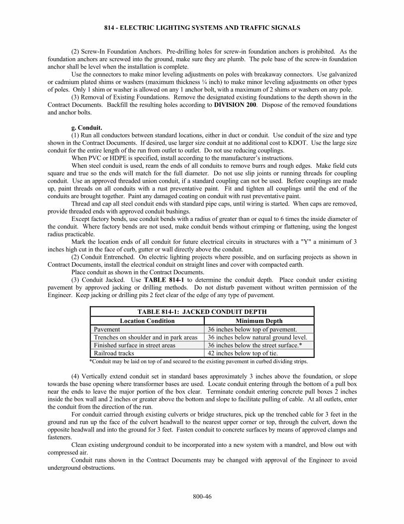
814 - ELECTRIC LIGHTING SYSTEMS AND TRAFFIC SIGNALS
800-46
(2) Screw-In Foundation Anchors. Pre-drilling holes for screw-in foundation anchors is prohibited. As the foundation anchors are screwed into the ground, make sure they are plumb. The pole base of the screw-in foundation anchor shall be level when the installation is complete. Use the connectors to make minor leveling adjustments on poles with breakaway connectors. Use galvanized or cadmium plated shims or washers (maximum thickness ¼ inch) to make minor leveling adjustments on other types of poles. Only 1 shim or washer is allowed on any 1 anchor bolt, with a maximum of 2 shims or washers on any pole. (3) Removal of Existing Foundations. Remove the designated existing foundations to the depth shown in the Contract Documents. Backfill the resulting holes according to DIVISION 200. Dispose of the removed foundations and anchor bolts.
g. Conduit. (1) Run all conductors between standard locations, either in duct or conduit. Use conduit of the size and type
shown in the Contract Documents. If desired, use larger size conduit at no additional cost to KDOT. Use the large size conduit for the entire length of the run from outlet to outlet. Do not use reducing couplings.
When PVC or HDPE is specified, install according to the manufacturer’s instructions. When steel conduit is used, ream the ends of all conduits to remove burrs and rough edges. Make field cuts
square and true so the ends will match for the full diameter. Do not use slip joints or running threads for coupling conduit. Use an approved threaded union conduit, if a standard coupling can not be used. Before couplings are made up, paint threads on all conduits with a rust preventative paint. Fit and tighten all couplings until the end of the conduits are brought together. Paint any damaged coating on conduit with rust preventative paint.
Thread and cap all steel conduit ends with standard pipe caps, until wiring is started. When caps are removed, provide threaded ends with approved conduit bushings.
Except factory bends, use conduit bends with a radius of greater than or equal to 6 times the inside diameter of the conduit. Where factory bends are not used, make conduit bends without crimping or flattening, using the longest radius practicable.
Mark the location ends of all conduit for future electrical circuits in structures with a "Y" a minimum of 3 inches high cut in the face of curb, gutter or wall directly above the conduit.
(2) Conduit Entrenched. On electric lighting projects where possible, and on surfacing projects as shown in Contract Documents, install the electrical conduit on straight lines and cover with compacted earth.
Place conduit as shown in the Contract Documents. (3) Conduit Jacked. Use TABLE 814-1 to determine the conduit depth. Place conduit under existing
pavement by approved jacking or drilling methods. Do not disturb pavement without written permission of the Engineer. Keep jacking or drilling pits 2 feet clear of the edge of any type of pavement.
TABLE 814-1: JACKED CONDUIT DEPTH Location Condition Minimum Depth
Pavement 36 inches below top of pavement. Trenches on shoulder and in park areas 36 inches below natural ground level. Finished surface in street areas 36 inches below the street surface.* Railroad tracks 42 inches below top of tie.
*Conduit may be laid on top of and secured to the existing pavement in curbed dividing strips. (4) Vertically extend conduit set in standard bases approximately 3 inches above the foundation, or slope
towards the base opening where transformer bases are used. Locate conduit entering through the bottom of a pull box near the ends to leave the major portion of the box clear. Terminate conduit entering concrete pull boxes 2 inches inside the box wall and 2 inches or greater above the bottom and slope to facilitate pulling of cable. At all outlets, enter the conduit from the direction of the run.
For conduit carried through existing culverts or bridge structures, pick up the trenched cable for 3 feet in the ground and run up the face of the culvert headwall to the nearest upper corner or top, through the culvert, down the opposite headwall and into the ground for 3 feet. Fasten conduit to concrete surfaces by means of approved clamps and fasteners.
Clean existing underground conduit to be incorporated into a new system with a mandrel, and blow out with compressed air.
Conduit runs shown in the Contract Documents may be changed with approval of the Engineer to avoid underground obstructions.
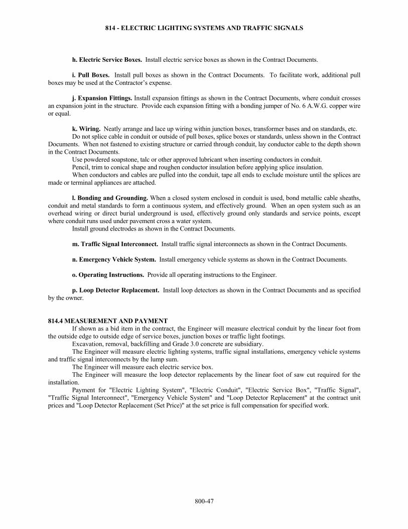
814 - ELECTRIC LIGHTING SYSTEMS AND TRAFFIC SIGNALS
800-47
h. Electric Service Boxes. Install electric service boxes as shown in the Contract Documents. i. Pull Boxes. Install pull boxes as shown in the Contract Documents. To facilitate work, additional pull
boxes may be used at the Contractor’s expense. j. Expansion Fittings. Install expansion fittings as shown in the Contract Documents, where conduit crosses
an expansion joint in the structure. Provide each expansion fitting with a bonding jumper of No. 6 A.W.G. copper wire or equal.
k. Wiring. Neatly arrange and lace up wiring within junction boxes, transformer bases and on standards, etc. Do not splice cable in conduit or outside of pull boxes, splice boxes or standards, unless shown in the Contract
Documents. When not fastened to existing structure or carried through conduit, lay conductor cable to the depth shown in the Contract Documents.
Use powdered soapstone, talc or other approved lubricant when inserting conductors in conduit. Pencil, trim to conical shape and roughen conductor insulation before applying splice insulation. When conductors and cables are pulled into the conduit, tape all ends to exclude moisture until the splices are
made or terminal appliances are attached. l. Bonding and Grounding. When a closed system enclosed in conduit is used, bond metallic cable sheaths,
conduit and metal standards to form a continuous system, and effectively ground. When an open system such as an overhead wiring or direct burial underground is used, effectively ground only standards and service points, except where conduit runs used under pavement cross a water system.
Install ground electrodes as shown in the Contract Documents. m. Traffic Signal Interconnect. Install traffic signal interconnects as shown in the Contract Documents. n. Emergency Vehicle System. Install emergency vehicle systems as shown in the Contract Documents. o. Operating Instructions. Provide all operating instructions to the Engineer. p. Loop Detector Replacement. Install loop detectors as shown in the Contract Documents and as specified
by the owner. 814.4 MEASUREMENT AND PAYMENT
If shown as a bid item in the contract, the Engineer will measure electrical conduit by the linear foot from the outside edge to outside edge of service boxes, junction boxes or traffic light footings.
Excavation, removal, backfilling and Grade 3.0 concrete are subsidiary. The Engineer will measure electric lighting systems, traffic signal installations, emergency vehicle systems
and traffic signal interconnects by the lump sum. The Engineer will measure each electric service box. The Engineer will measure the loop detector replacements by the linear foot of saw cut required for the
installation. Payment for "Electric Lighting System", "Electric Conduit", "Electric Service Box", "Traffic Signal",
"Traffic Signal Interconnect", "Emergency Vehicle System" and "Loop Detector Replacement" at the contract unit prices and "Loop Detector Replacement (Set Price)" at the set price is full compensation for specified work.
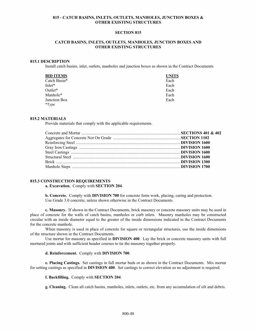
815 - CATCH BASINS, INLETS, OUTLETS, MANHOLES, JUNCTION BOXES & OTHER EXISTING STRUCTURES
800-48
SECTION 815
CATCH BASINS, INLETS, OUTLETS, MANHOLES, JUNCTION BOXES AND OTHER EXISTING STRUCTURES
815.1 DESCRIPTION Install catch basins, inlet, outlets, manholes and junction boxes as shown in the Contract Documents. BID ITEMS UNITS Catch Basin* Each Inlet* Each Outlet* Each Manhole* Each Junction Box Each *Type 815.2 MATERIALS
Provide materials that comply with the applicable requirements. Concrete and Mortar .............................................................................................. SECTIONS 401 & 402 Aggregates for Concrete Not On Grade ................................................................ SECTION 1102 Reinforcing Steel ................................................................................................... DIVISION 1600 Gray Iron Castings ................................................................................................ DIVISION 1600 Steel Castings ........................................................................................................ DIVISION 1600 Structural Steel ...................................................................................................... DIVISION 1600 Brick ...................................................................................................................... DIVISION 1300 Manhole Steps ....................................................................................................... DIVISION 1700
815.3 CONSTRUCTION REQUIREMENTS a. Excavation. Comply with SECTION 204. b. Concrete. Comply with DIVISION 700 for concrete form work, placing, curing and protection. Use Grade 3.0 concrete, unless shown otherwise in the Contract Documents.
c. Masonry. If shown in the Contract Documents, brick masonry or concrete masonry units may be used in place of concrete for the walls of catch basins, manholes or curb inlets. Masonry manholes may be constructed circular with an inside diameter equal to the greater of the inside dimensions indicated in the Contract Documents for the concrete manhole.
When masonry is used in place of concrete for square or rectangular structures, use the inside dimensions of the structure shown in the Contract Documents.
Use mortar for masonry as specified in DIVISION 400. Lay the brick or concrete masonry units with full mortared joints and with sufficient header courses to tie the masonry together properly. d. Reinforcement. Comply with DIVISION 700.
e. Placing Castings. Set castings in full mortar beds or as shown in the Contract Documents. Mix mortar for setting castings as specified in DIVISION 400. Set castings to correct elevation so no adjustment is required. f. Backfilling. Comply with SECTION 204. g. Cleaning. Clean all catch basins, manholes, inlets, outlets, etc. from any accumulation of silt and debris.
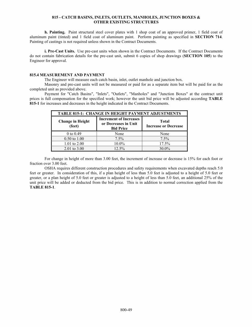
815 - CATCH BASINS, INLETS, OUTLETS, MANHOLES, JUNCTION BOXES & OTHER EXISTING STRUCTURES
800-49
h. Painting. Paint structural steel cover plates with 1 shop coat of an approved primer, 1 field coat of aluminum paint (tinted) and 1 field coat of aluminum paint. Perform painting as specified in SECTION 714. Painting of castings is not required unless shown in the Contract Documents. i. Pre-Cast Units. Use pre-cast units when shown in the Contract Documents. If the Contract Documents do not contain fabrication details for the pre-cast unit, submit 6 copies of shop drawings (SECTION 105) to the Engineer for approval. 815.4 MEASUREMENT AND PAYMENT The Engineer will measure each catch basin, inlet, outlet manhole and junction box. Masonry and pre-cast units will not be measured or paid for as a separate item but will be paid for as the completed unit as provided above. Payment for "Catch Basins", "Inlets", "Outlets", "Manholes" and "Junction Boxes" at the contract unit prices is full compensation for the specified work; however the unit bid price will be adjusted according TABLE 815-1 for increases and decreases in the height indicated in the Contract Documents.
TABLE 815-1: CHANGE IN HEIGHT PAYMENT ADJUSTMENTS
Change in Height (feet)
Increment of Increases or Decreases in Unit
Bid Price
Total Increase or Decrease
0 to 0.49 None None 0.50 to 1.00 7.5% 7.5% 1.01 to 2.00 10.0% 17.5% 2.01 to 3.00 12.5% 30.0%
For change in height of more than 3.00 feet, the increment of increase or decrease is 15% for each foot or fraction over 3.00 feet. OSHA requires different construction procedures and safety requirements when excavated depths reach 5.0 feet or greater. In consideration of this, if a plan height of less than 5.0 feet is adjusted to a height of 5.0 feet or greater, or a plan height of 5.0 feet or greater is adjusted to a height of less than 5.0 feet, an additional 25% of the unit price will be added or deducted from the bid price. This is in addition to normal correction applied from the TABLE 815-1.
816 - ADJUSTMENT OF INLETS, MANHOLES & OTHER EXISTING STRUCTURES
800-50
SECTION 816
ADJUSTMENT OF INLETS, MANHOLES AND OTHER EXISTING STRUCTURES 816.1 DESCRIPTION Adjust inlets, manholes and other existing structures as shown in the Contract Documents. BID ITEMS UNITS Adjustment of Catch Basins Each Adjustment of Curb Inlets Each Adjustment of Manholes Each
Adjustment of Manholes (Set Price) Each Structural Steel Pound Cast Steel Pound Cast Iron Pound Adjustment of Meter Box (*) Each Adjustment of Valve Box (*) Each
Adjustment of Existing Structures Lump Sum * Type 816.2 MATERIALS
Provide materials that comply with the applicable requirements. Concrete and Mortar .............................................................................................. SECTIONS 401 & 402 Aggregates for Concrete Not On Grade ................................................................ SECTION 1102 Reinforcing Steel ................................................................................................... DIVISION 1600 Gray Iron Castings ................................................................................................ DIVISION 1600 Steel Castings ........................................................................................................ DIVISION 1600 Structural Steel ...................................................................................................... DIVISION 1600 Brick ...................................................................................................................... DIVISION 1300 Existing Structures ................................................................................................ DIVISIONS 1000-2500
816.3 CONSTRUCTION REQUIREMENTS
Carefully remove and reinstall or store structural steel or cast fixtures for future use by the owners as shown in the Contract Documents. If the height of brick walls is increased, the addition may be of brick, masonry units or Grade 3.0 concrete, unless shown otherwise in the Contract Documents. Masonry brick salvaged from the project and in good condition may be used to increase the height of the walls. If no bricks are salvaged, provide new brick or concrete blocks. Place masonry, concrete and castings according to DIVISION 800.
Adjust existing manholes by raising the frame to the desired grade using adjustable metal extension rings. Use adjusting rings of an approved type and rigidly secure to the existing frame by approved methods. Make the adjustment at any one location by using a maximum of 2 adjustment rings. Salvage existing manhole covers and reuse in the adjustment.
Use methods for the adjustment of meter or valve boxes according to the requirements of the utility company involved.
Adjust existing structures as shown in the Contract Documents. If the existing structure is damaged during the adjustment operations, replace any damaged materials with new materials matching the originals. 816.4 MEASUREMENT AND PAYMENT The Engineer will measure each adjustment of catch basin, inlet, manhole, meter box and valve box. The Engineer will measure structural steel, cast steel and cast iron by the pound as provided in DIVISION 700. The Engineer will measure the adjustment of existing structures by the lump sum. Payment for "Adjustment of Catch Basins", "Adjustment of Curb Inlets", "Adjustment of Manholes", "Structural Steel", "Cast Steel", "Cast Iron" "Adjustment of Meter Box (*)", "Adjustment of Valve Box (*)" and "Adjustment of Existing Structures" at the contract unit prices and "Adjustment of Manholes" at the contract set price is full compensation for the specified work.
817 - PIPE CULVERTS, EROSION PIPE, STORM SEWERS, SANITARY SEWERS & END SECTIONS
800-51
SECTION 817
PIPE CULVERTS, EROSION PIPE, STORM SEWERS, SANITARY SEWERS AND END SECTIONS
817.1 DESCRIPTION Install the size and type of pipe culvert, erosion pipe, storm sewer, sanitary sewer, end section and concrete
headwall specified in the Contract Documents. Provide materials for, and construct the sanitary sewer system as shown in the Contract Documents. BID ITEMS UNITS Entrance Pipe (*) (**) (+) (++) (^) (^^) Linear Foot Cross Road Pipe (*) (**) (+) (++) (^) (^^) Linear Foot Erosion Pipe (*) (**) (+) (++) (^) (^^) Linear Foot Storm Sewer (*) (**) (^) (^^) Linear Foot Sanitary Sewer (*) (**) Linear Foot End Section (*) (**) (+) (++) Each Concrete Headwall Each Fly Ash Slurry Grout (xx) Cubic Yard Sanitary Sewer System Lump Sum *Size **Type +Provide Only ++Install Only xx High Strength or Low Strength ^BC-Bituminous Coated ^^FP-Fully Paved
TYPES OF PIPES RCP - Round Reinforced Concrete Pipe RCPA - Reinforced Concrete Pipe-Arch RCPHE - Reinforced Concrete Pipe Horizontal Elliptical CSP - Galvanized Round Corrugated Steel Pipe CSMAC - Galvanized Corrugated Steel - Metal Arch Culvert ACSP - Aluminized (Type 2) Round Corrugated Steel Pipe ACSMAC - Aluminized (Type 2) Corrugated Steel - Metal Arch Culvert CAP - Round Corrugated Aluminum Pipe CAMAC - Corrugated Aluminum - Metal Arch Culvert PEP - Polyethylene Pipe CIP - Cast Iron Pipe CIPP - Cast Iron Pressure Pipe CISP - Cast Iron Soil Pipe PVCP - Polyvinyl Chloride Pipe TYPES OF END SECTIONS RC - Round Reinforced Concrete RCA - Reinforced Concrete Arch RCHE - Reinforced Concrete Horizontal Elliptical CS - Galvanized Round Corrugated Steel CSMA - Galvanized Corrugated Steel - Metal Arch ACS - Aluminized Corrugated Steel CA - Round Corrugated Aluminum ACSMA - Aluminized (Type 2) Corrugated Steel - Metal Arch CAMA - Corrugated Aluminum - Metal Arch
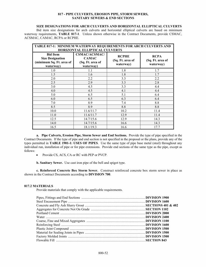
817 - PIPE CULVERTS, EROSION PIPE, STORM SEWERS, SANITARY SEWERS & END SECTIONS
800-52
SIZE DESIGNATIONS FOR ARCH CULVERTS AND HORIZONTAL ELLIPTICAL CULVERTS Bid item size designations for arch culverts and horizontal elliptical culverts are based on minimum waterway requirements, TABLE 817-1. Unless shown otherwise in the Contract Documents, provide CSMAC, ACSMAC, CAMAC, RCPA or RCPHE.
TABLE 817-1: MINIMUM WATERWAY REQUIREMENTS FOR ARCH CULVERTS AND HORIZONTAL ELLIPTICAL CULVERTS
Bid Item Size Designation
(minimum Sq. Ft. area of waterway)
CSMAC/ACSMAC/CAMAC
(Sq. Ft. area of waterway)
RCPHE (Sq. Ft. area of
waterway)
RCPA (Sq. Ft. area of
waterway)
1.0 1.1 1.8 1.7 1.5 1.6 1.8 1.7 2.0 2.2 3.3 2.2 2.5 2.9 3.3 2.8 3.0 4.5 3.3 4.4 4.0 4.5 4.1 4.4 5.0 6.5 5.1 6.4 6.0 6.5 6.3 6.4 7.0 8.9 7.4 8.8 8.5 8.9 8.8 8.8
10.0 11.6/11.7 10.2 11.4 11.0 11.6/11.7 12.9 11.4 12.5 14.7/15.6 12.9 14.3 14.0 14.7/15.6 16.6 14.3 16.5 18.1/19.3 16.6 17.7
a. Pipe Culverts, Erosion Pipe, Storm Sewer and End Sections. Provide the type of pipe specified in the
Contract Documents. If the type of pipe and end section is not specified in the proposal or the plans, provide any of the types permitted in TABLE 1901-1: USES OF PIPES. Use the same type of pipe base metal (steel) throughout any individual run, installation of pipe or for pipe extensions. Provide end sections of the same type as the pipe, except as follows:
Provide CS, ACS, CA or RC with PEP or PVCP. b. Sanitary Sewer. Use cast iron pipe of the bell and spigot type. c. Reinforced Concrete Box Storm Sewer. Construct reinforced concrete box storm sewer in place as shown in the Contract Documents according to DIVISION 700. 817.2 MATERIALS
Provide materials that comply with the applicable requirements. Pipes, Fittings and End Sections ........................................................................... DIVISION 1900 Steel Encasement Pipe ........................................................................................... DIVISION 1600 Concrete and Fly Ash Slurry Grout ....................................................................... SECTIONS 401 & 402 Aggregates for Concrete Not On Grade ................................................................ SECTION 1102 Portland Cement .................................................................................................... DIVISION 2000 Water ..................................................................................................................... DIVISION 2400 Coarse, Fine and Mixed Aggregates ..................................................................... DIVISION 1100 Reinforcing Steel ................................................................................................... DIVISION 1600 Plastic Joint Compound ......................................................................................... DIVISION 1500 Material for Sealing Joints in Pipes ....................................................................... DIVISION 1500 Factory Molded Joints ........................................................................................... DIVISION 1500 Flowable Fill ......................................................................................................... SECTION 843
817 - PIPE CULVERTS, EROSION PIPE, STORM SEWERS, SANITARY SEWERS & END SECTIONS
800-53
Provide materials for the sanitary sewer system as shown in the Contract Documents.
The Engineer will accept the materials for the sanitary sewer system based on catalog cuts, product data (including general bulletins), materials of construction, manufacturer’s certifications or affidavits of compliance with specified standards, and visual inspection for compliance with dimensional and other requirements detailed in the Contract Documents.
817.3 CONSTRUCTION REQUIREMENTS a. General. If PEP or PVCP pipe is used, prior to the pre-construction conference, submit for evaluation by
the Engineer, a résumé of experience installing PEP or PVCP. A representative of the manufacturer of PEP or PVCP must attend the pre-construction conference for all projects where the Contractor has minimal or no experience with PEP or PVCP installation, or if no résumé is submitted.
If "Provide Only" is specified, provide and deliver the pipe, coupling bands and end sections to the storage location shown in the Contract Documents. If "Install Only" is specified, KDOT will provide the pipe, coupling bands and end sections. The location of the materials is shown in the Contract Documents. If neither "Provide Only" or "Install Only" is designated, provide and install the pipe, coupling band and end sections as shown in the Contract Documents. Use Grade 3.0 concrete to construct headwalls for erosion pipe. Perform formwork, placing, curing and protection of concrete according to DIVISION 700.
If aluminum pipe or aluminized corrugated steel pipe is to come in contact with fresh portland cement concrete or grout, completely cover the contact area of the pipe with an asphaltic paint (approved by the Field Engineer) to prevent corrosion.
b. Excavation. (1) General. Beginning at the outlet end and proceeding toward the upper end, excavate the bottom of the
channel to the line, grade and elevation shown in the Contract Documents. Construct the width of the trench sufficient to lay and backfill the pipe with a minimum width equal to the diameter of the pipe plus 6 inches on each side.
Follow OSHA safety regulations for sloping the sides of excavations. Use shoring and bracing as required. Do not disturb any railroad, existing street or highway, when tunneling underneath is required (See
SECTION 819 for tunneling, jacking or boring requirements). Methods of tunneling are subject to Engineer approval.
When it is required to remove an existing street or highway surface in constructing the pipe or sewer, replace the surface with an equivalent material at Contractor’s expense, unless otherwise shown in the Contract Documents.
Firm the foundation in the trench to prevent subsequent settlement. Remove soft, unstable materials and replace with suitable materials. If the foundation is on firm earth, pare or mold the earth to give full support to each pipe for a depth a minimum of ¼ the external diameter of the pipe. When bell and spigot pipe is used, cut notches to receive the bell.
The Contractor may undercut the trench and backfill with sand or other suitable material to obtain proper, uniform bearing of the pipe at no additional cost to KDOT.
If rock is encountered, remove the rock to an elevation 12 inches below the elevation shown in the Contract Documents for the bottom of the channel. If blasting is used to remove rock, take the precautions to protect the previously placed portions of the structure. Backfill and compact the bottom 12 inches of the excavation with soil from the roadway excavation. If the foundation is in rock, place an equalizing bed a minimum of 6 inches thick of well-compacted sand or similar material upon the rock.
When shown in the Contract Documents, or ordered in writing by the Engineer, place a concrete cradle or encasement under or around the pipe to provide a suitable foundation for the pipe. Use the dimensions and grade of concrete as shown in the Contract Documents, or as directed by the Engineer. (2) Pipes and Culverts 3 feet or less in diameter. While excavating, use a template to shape the bottom of the channel so that at least 10% of the overall height of the pipe or culvert is in contact with the bottom of the channel. Excavate recesses into the channel to accept all protrusions from the perimeter of the pipe or culvert.
Alternate methods of bedding the pipe or culvert:
817 - PIPE CULVERTS, EROSION PIPE, STORM SEWERS, SANITARY SEWERS & END SECTIONS
800-54
Place a bed of granular material (4 inch minimum thickness) on the bottom of the channel, and then use a template to shape the granular material to accept the culvert.
Place the pipe or culvert on the bottom of the channel, then place and tamp granular material (4 inch minimum thickness) under the haunch area of the pipe or culvert.
(3) Pipes and Culverts greater than 3 feet in diameter. Excavate recesses into the channel to accept all
protrusions from the perimeter of the pipe or culvert. After the pipe or culvert is placed on the bottom of the channel, place and tamp granular material under the haunch area of the pipe or culvert so that 20% of the overall height of the pipe or culvert is bedded in the granular material.
An alternate method of bedding the pipe or culvert is to place and compact a bed of granular material (approximately half the total quantity needed) on the bottom of the channel, then use a template to shape the granular material to accept the pipe or culvert. Place and tamp the remainder of the granular material after the pipe or culvert is placed so that 20% of the overall height of the pipe or culvert is bedded in the granular material. (4) Polyethylene (PEP) and Polyvinyl Chloride (PVCP) Pipe. Excavate and form a bed for PEP and PVCP according to subsections 817.3b.(1) thru (3) and the following additions and exceptions:
The minimum trench width = (1 ½ x pipe diameter) + 12 inches. The space between the pipe and the trench wall shall be wider than the compaction equipment used in the
pipe zone. The trench width in unsupported, unstable soils will depend on the size of the pipe, the stiffness of the
backfill and insitu soil, and the depth of cover. Place a 6 inch (minimum) equalizing bed of pipe backfill (PB) upon the foundation as specified in
SECTION 1107. c. Laying. Do not lay pipe until the Engineer approves the foundation bed. (1) General. When placing 2 or more pipe culverts adjacent to each other, separate the pipe culverts by a
distance equal to a minimum of ½ the diameter of the pipe. The minimum distance for pipe culverts is 18 inches, and the minimum distance for metal arch culverts is 24 inches.
Before installing corrugated steel pipe, repair any damage to the metallic coating on the pipe. Clean the damaged area to bright metal by blast cleaning, power disk sanding or wire brushing. Apply zinc-rich paint over the cleaned area. Use zinc-rich paint to repair both aluminized and galvanized coatings. Before installing asphalt coated pipe, repair any damage to the asphalt coating on the pipe. Use material that is compatible with the original asphalt coating. The repaired area shall have the same thickness as the original asphalt coating. For erosion pipe, weld any bends or angles prior to applying the asphalt coating.
In finished trenches, start laying pipe at the outlet end so the spigot ends (when bell and spigot pipe is used) point to the direction of flow. Install all pipes true to line and grade, with ends abutting. When using multiple sections of pipe in an individual run, place the longest section at the upstream end, the next longest section at the outlet end, and shorter sections in the middle of the run. When installing spiral, corrugated pipe, rotate the sections during installation so that the corrugations on the end of one section match those on the end of the adjoining section. Lay pipe in the bed so the lower portion of each pipe is supported for its entire length to a depth a minimum of ¼ the external diameter of the pipe. When laid in the trench, fit and match pipes to form a smooth, uniform invert. Carefully clean bell ends before pipes are lowered into the trenches. Avoid unnecessary handling in the trench when lowering. Place sections of corrugated metal pipe with the ends abutting and join with the manufacturer’s coupling bands. Install and tighten the coupling bands according to the manufacturer’s recommendations.
Cement joints of pipe over 24 inches in diameter with a cement mortar or plastic joint compound. Use cement mortar composed of 1 part portland cement and 3 parts fine aggregate mixed with sufficient water to form a plastic mortar. As each section of pipe is laid, clean the bell or hub of the preceding pipe and fill the bottom portion with mortar. After the pipe is placed, fill the remaining portion of the joint. Smooth finish and wipe clean the inside of the joint. After the initial set, protect the mortar on the outside from the sun using soil or other approved covering. Prepare and apply plastic joint compound according to the manufacturer’s recommendations. On 24 inch or smaller RCP’s, use plastic joint compound to join the sections.
(2) Polyethylene (PEP) and Polyvinyl Chloride (PVCP) Pipe. Install PE and PVC pipes according to subsection 817.3c. and the following additions and exceptions:
Assemble PEP and PVCP according to the manufacturer’s instructions, starting at the downstream end. Properly assemble the gasketed bell and spigot joints to prevent the infiltration of soil fines.
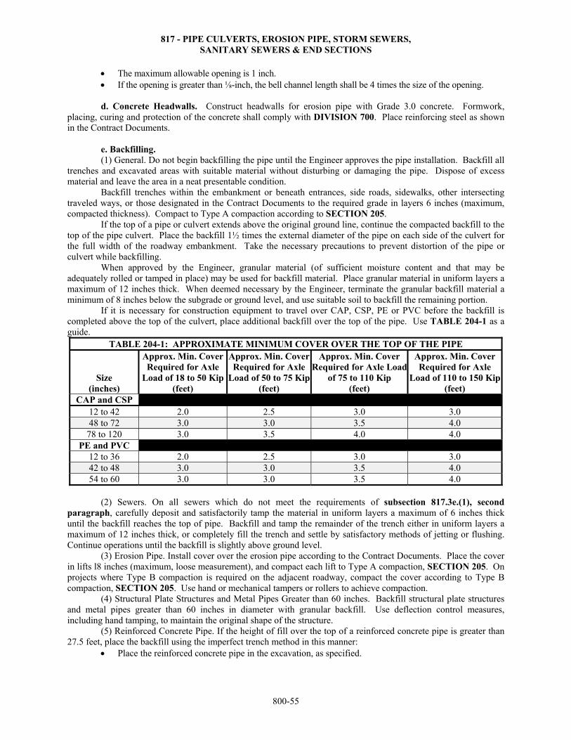
817 - PIPE CULVERTS, EROSION PIPE, STORM SEWERS, SANITARY SEWERS & END SECTIONS
800-55
The maximum allowable opening is 1 inch. If the opening is greater than ⅛-inch, the bell channel length shall be 4 times the size of the opening.
d. Concrete Headwalls. Construct headwalls for erosion pipe with Grade 3.0 concrete. Formwork, placing, curing and protection of the concrete shall comply with DIVISION 700. Place reinforcing steel as shown in the Contract Documents.
e. Backfilling.
(1) General. Do not begin backfilling the pipe until the Engineer approves the pipe installation. Backfill all trenches and excavated areas with suitable material without disturbing or damaging the pipe. Dispose of excess material and leave the area in a neat presentable condition. Backfill trenches within the embankment or beneath entrances, side roads, sidewalks, other intersecting traveled ways, or those designated in the Contract Documents to the required grade in layers 6 inches (maximum, compacted thickness). Compact to Type A compaction according to SECTION 205.
If the top of a pipe or culvert extends above the original ground line, continue the compacted backfill to the top of the pipe culvert. Place the backfill 1½ times the external diameter of the pipe on each side of the culvert for the full width of the roadway embankment. Take the necessary precautions to prevent distortion of the pipe or culvert while backfilling. When approved by the Engineer, granular material (of sufficient moisture content and that may be adequately rolled or tamped in place) may be used for backfill material. Place granular material in uniform layers a maximum of 12 inches thick. When deemed necessary by the Engineer, terminate the granular backfill material a minimum of 8 inches below the subgrade or ground level, and use suitable soil to backfill the remaining portion.
If it is necessary for construction equipment to travel over CAP, CSP, PE or PVC before the backfill is completed above the top of the culvert, place additional backfill over the top of the pipe. Use TABLE 204-1 as a guide.
TABLE 204-1: APPROXIMATE MINIMUM COVER OVER THE TOP OF THE PIPE
Size (inches)
Approx. Min. Cover Required for Axle
Load of 18 to 50 Kip (feet)
Approx. Min. Cover Required for Axle
Load of 50 to 75 Kip(feet)
Approx. Min. Cover Required for Axle Load
of 75 to 110 Kip (feet)
Approx. Min. Cover Required for Axle
Load of 110 to 150 Kip(feet)
CAP and CSP 12 to 42 2.0 2.5 3.0 3.0 48 to 72 3.0 3.0 3.5 4.0
78 to 120 3.0 3.5 4.0 4.0 PE and PVC
12 to 36 2.0 2.5 3.0 3.0 42 to 48 3.0 3.0 3.5 4.0 54 to 60 3.0 3.0 3.5 4.0
(2) Sewers. On all sewers which do not meet the requirements of subsection 817.3e.(1), second paragraph, carefully deposit and satisfactorily tamp the material in uniform layers a maximum of 6 inches thick until the backfill reaches the top of pipe. Backfill and tamp the remainder of the trench either in uniform layers a maximum of 12 inches thick, or completely fill the trench and settle by satisfactory methods of jetting or flushing. Continue operations until the backfill is slightly above ground level. (3) Erosion Pipe. Install cover over the erosion pipe according to the Contract Documents. Place the cover in lifts l8 inches (maximum, loose measurement), and compact each lift to Type A compaction, SECTION 205. On projects where Type B compaction is required on the adjacent roadway, compact the cover according to Type B compaction, SECTION 205. Use hand or mechanical tampers or rollers to achieve compaction.
(4) Structural Plate Structures and Metal Pipes Greater than 60 inches. Backfill structural plate structures and metal pipes greater than 60 inches in diameter with granular backfill. Use deflection control measures, including hand tamping, to maintain the original shape of the structure. (5) Reinforced Concrete Pipe. If the height of fill over the top of a reinforced concrete pipe is greater than 27.5 feet, place the backfill using the imperfect trench method in this manner:
Place the reinforced concrete pipe in the excavation, as specified.
817 - PIPE CULVERTS, EROSION PIPE, STORM SEWERS, SANITARY SEWERS & END SECTIONS
800-56
Place and compact the earthen backfill to a height above the top of the pipe equal to the external width of the pipe.
After the backfill is placed and compacted as specified, excavate the compacted earth from the prism directly over the pipe.
Backfill the resulting trench with earth placed in the loosest possible condition. After the trench is filled with loose earth, construct the remainder of the embankment as specified in
the Contract Documents. (6) Polyethylene (PEP) and Polyvinyl Chloride (PVCP) Pipe. Backfill PEP and PVCP with either granular backfill or flowable fill, according to subsection 817.3e., with these additions and exceptions:
If the fill from the top of pipe to the top of the subgrade is 3 feet or less, backfill with granular material to the top of the subgrade.
If the fill from the top of pipe to the top of the subgrade is greater than 3 feet, backfill with granular material to a point 1 foot above the top of the pipe.
Prevent damaging or floating the pipe during the backfilling operations. Do not deform or damage the pipe while compacting the granular backfill. Hand tamping may be necessary adjacent to the pipe to prevent distortion.
The maximum barrel deflection of the pipe (reduction of the barrel nominal base inside diameter) shall not exceed 5%. Use a mandrel to measure the barrel deflection of the pipe. Take the measurement at least 30 days after the installation and backfilling. If oversized diameter pipes are installed, actual inside pipe diameters may need to be considered. Remove, reinstall or replace any pipes deformed more than 5%.
A minimum of 30 days following the installation and backfilling, measure the barrel deflection of each pipe run.
Measure the deflection using a mandrel or any other device (approved by the Engineer) that can physically verify the dimensions of the pipe and is not limited by poor lighting, water-flow, pipe length or other limiting conditions of the installed environment. Measure the deflection in the presence of the Engineer.
Pipes larger than 24 inches may be entered and deflection levels measured directly. Take a measurement once every 10 feet for the length of the pipe.
If a mandrel is used for the deflection test, use a 9 (or greater odd number) arm mandrel, sized to the actual inside diameter of the pipe installed, and inspected by the Engineer prior to testing. Use a properly sized proving ring to check or test the mandrel for accuracy. Pull the mandrel through the pipe by hand with a rope or cable. When applicable, incorporate pulleys into the system to change the direction of pull so that inspection personnel need not physically enter the pipe or manhole.
If any pipes deform between 5% and 7.5%, conduct an evaluation (by a licensed Professional Engineer) and submit to the Engineer for review and approval. In the evaluation consider the severity of the deflection, structural integrity, environmental conditions and the design service life of the pipe. The Engineer may require removal, reinstallation or replacement of the pipe where the evaluation indicates that the deflection could be problematic.
The maximum barrel deflection of the pipe (reduction of the barrel based on the actual inside diameter) is 7.5%. Remove and reinstall or replace, as directed by the Engineer, any pipes deformed more than 7.5%. c. Cast Iron Pressure Pipes for Sanitary Sewers. Handle according to this specification with the following additions and exceptions. (1) Handling. Do not injure the pipe or pipe coating. Do not place any pipe or material inside of a pipe or fitting after the coating is applied. (2) Cutting. Cut the pipe without damaging. (3) Placing and Laying. While suspended in the sling and before lowering into the trench, the Engineer will inspect the pipe for defects by tapping lightly with a hammer. Damaged pipe will be rejected. Carefully embed the pipe with bell holes excavated so each pipe will rest firmly upon its bed for the full length. After placing a length of pipe in the trench, hold the packing material for the joint around the bottom of the spigot so the packing enters the bell as the pipe is pushed into position. Center the spigot in the bell and push the pipe into position in the required alignment. Lay pipe with the bells facing the direction of laying, except where necessary in making connections with other lines. Position a minimum of 2 lengths of pipe ahead of each joint, with packing installed and earth fill tamped alongside the pipe before the joint is poured, except at closures.
817 - PIPE CULVERTS, EROSION PIPE, STORM SEWERS, SANITARY SEWERS & END SECTIONS
800-57
(4) Joints. Before jointing bell and spigot pipe, remove all lumps, blisters, excess coating materials, oil and grease from the bell and spigot ends of the pipe. Rub with a wire brush, wipe clean and dry the outside spigot and inside of the bell. Carefully place the packing, and tightly caulk to a uniform thickness. No loose or frayed ends of fiber may protrude into the space to be filled with joint filler. Carefully inspect each joint and check for proper depth before the joint runner is attached. The depth of load in lead filled joints shall be a minimum of 2 ¼ inches back of the face of the bell. In a melting pot near the joint to be poured, heat lead to the proper temperature so that when stirred the surface will show a rapid change in color. Before pouring lead, remove all scum. On the outside of the pipe, dam the pouring gate with clay to fill the joint even with the top of the bell. Make each joint with 1 pour completely filling the joint space. Caulk toward the joint gate to secure tight joints without overstraining the bells. If the packing has been insufficiently caulked, permitting the lead to be driven to a depth more than ¼ inch from the face of the bell at any point during caulking, remove the lead and remake the joint.
d. Sanitary Sewer System. Install the sanitary sewer system as shown in the Contract Documents. Make all service connections unless specified otherwise in the Contract Documents. Use Grade 3.5 concrete that complies with SECTION 401 unless specified otherwise in the Contract Documents. 817.4 MEASUREMENT AND PAYMENT
The Engineer will measure all types of pipe by the linear foot, along the centerline of the pipe. Gain in pipe length due to the fit of the pipe sections at the coupling bands or joints is not measured for payment.
The Engineer will measure each end section, concrete headwall and sanitary sewer system. The Engineer will measure fly ash slurry grout by the cubic yard. The Engineer will not measure excavation for separate payment. Payment for "Entrance Pipe", "Cross Road Pipe", "Erosion Pipe", "Storm Sewer", "Sanitary Sewer", "End
Section", "Concrete Headwall", "Fly Ash Slurry Grout" and "Sanitary Sewer System" at the contract unit prices is full compensation for the specified work.
818 - ENCASEMENT PIPE
800-58
SECTION 818
ENCASEMENT PIPE 818.1 DESCRIPTION Install the size and type of encasement pipe specified in the Contract Documents. BID ITEM UNITS Encasement Pipe (*) (**) (***) Linear Foot *Size **Type ***Method 818.2 MATERIALS Provide the size and type of encasement pipe specified in the Contract Documents. 818.3 CONSTRUCTION REQUIREMENTS Install the encasement pipe as detailed in the Contract Documents. The Engineer must approve the methods used to install the encasement pipe. Connect the encasement pipe as recommended by the manufacturer. If the Contract Documents specify compaction, backfill and compact the excavation according to DIVISION 200. 818.4 MEASUREMENT AND PAYMENT The Engineer will measure encasement pipe by the linear foot, along the centerline of the pipe. Payment for the "Encasement Pipe" at the contract unit price is full compensation for the specified work.
819 - BORED, JACKED OR TUNNELED PIPE
800-59
SECTION 819
BORED, JACKED OR TUNNELED PIPE 819.1 DESCRIPTION Install the designated pipe by boring, jacking or tunneling as shown in the Contract Documents. If the method of installation is not specified in the Contract Documents, the Contractor has the option to use any of the 3 methods. BID ITEMS UNITS * Pipe (Bored, Jacked or Tunneled) Linear Foot *Type and Size of Pipe 819.2 MATERIALS Provide materials that comply with the applicable requirements.
Pipe ........................................................................................................................ DIVISIONS 1600/1900 Grout ..................................................................................................................... SECTION 401
819.3 CONSTRUCTION REQUIREMENTS a. General. If the pipe is bored, jacked or tunneled under a highway, railroad, street or other structure, the installation of the pipe shall not interfere with the operation of the highway, railroad, street or other structure. Do not weaken or damage existing roadbeds or structures. If the grade of the pipe (at the point of boring, jacking or tunneling) is below ground, construct the pits or trenches necessary to install the pipe complying with OSHA requirements. Backfill such pits and trenches upon completion of the pipe installation. Compact the backfill to Type A, MR-5-5, SECTION 205. Submit to the Engineer for approval a detailed plan for the proposed method of installing the pipe. Install the pipe beginning at the lower elevation (downstream) and progressing to the higher elevation (upstream). Do not vary the final position of the pipe from the specified line or grade more than 1 inch in 10 feet. Variations, if any, shall be regular and in one direction. The flowline shall be in the specified direction. Repair or replace, as determined by the Engineer, all pipes damaged or misaligned during the boring, jacking or tunneling operations. b. Boring. Use either a pilot hole or the auger method. (1) Pilot Hole Method. Bore a pilot hole (approximately 2 inches) the length of the crossing. Before boring the larger hole, check the pilot hole for line and grade at the opposite end of the bore from the work pit. The pilot hole serves as the centerline of the larger hole bored later. (2) Auger Method. Use a steel encasement pipe (of the approximate diameter of the pipe to be installed) equipped with a cutter head to perform the excavation. Use augers of sufficient size to convey the excavated material to the work pit. In unconsolidated soil formations, the Engineer will permit the use of a gel-forming colloidal drilling fluid (with a minimum of 10% high grade, bentonite) to consolidate the cuttings, seal the walls of the hole, lubricate the removal of the cuttings and lubricate the immediate installation of the pipe. c. Jacking. Use heavy duty jacks suitable for the intended purpose. Use a jacking head and bracing between the jacks and the jacking head, to apply uniform pressure around the ring of pipe. The Engineer will allow the use of joint cushioning material. Use a jacking frame or backstop. Use guides that support and direct the pipe in the proper line and grade. As the pipe is jacked, excavate the material just ahead of the pipe (a maximum of 2 feet in advance). Remove the excavated material through the pipe. Excavation for the underside of the pipe, for a minimum of ⅓ of the circumference of the pipe, shall follow the contour and grade of the pipe. Over-excavation (maximum of 2 inches) for the upper half of the pipe is allowed. The over-excavation shall taper to nothing at the point the
819 - BORED, JACKED OR TUNNELED PIPE
800-60
excavation conforms to the contour of the pipe. Fill over-excavation in excess of 1 inch with a slurry grout the length of the installation after the pipe is installed. The Engineer may allow the use of a cutting head of steel plate around the head end of the pipe. The cutting edge may extend a short distance beyond the end of the pipe. Construct (with inside angles or lugs) the cutting edge to prevent it from slipping back into the pipe. When the pipe jacking operations begin, to the extent possible, continue the operations without interruptions to prevent the pipe from becoming firmly set in the excavation. d. Tunneling. Use a tunnel lining of sufficient strength to support the overburden. Fill the space between the tunnel lining and the limits of the excavation with slurry grout. Provide access holes in the tunnel lining (maximum spacing of 10 feet) for the grouting operations. 819.4 MEASUREMENT AND PAYMENT The Engineer will measure pipe by the foot along the centerline of the pipe. Gain in pipe length due to the fit of the pipe sections at the coupling bands or joints is not measured for payment. Payment for the specified "Pipe (Bored, Jacked or Tunneled)" at the contract unit price is full compensation for the specified work.
820 - FLUME INLETS AND SLOPE DRAINS
800-61
SECTION 820
FLUME INLETS AND SLOPE DRAINS 820.1 DESCRIPTION Construct the designated type of flume inlets and slope drains as shown in the Contract Documents. BID ITEMS UNITS Flume Inlet (*) Each Slope Drain (*) Linear Foot Slope Drain (Special) Linear Foot *Type: concrete, grouted stone or stone 820.2 MATERIALS
Provide materials that comply with the applicable requirements.
Concrete and Grout ............................................................................................... SECTIONS 401 & 402 Aggregates for Concrete Not On Grade ................................................................ SECTION 1102 Stone for Flume Inlets and Slope Drains ............................................................... DIVISION 1100 Type 2 Liquid Membrane-Forming Compound .................................................... DIVISION 1400 Reinforcing Steel ................................................................................................... DIVISION 1600 Welded Steel Wire Fabric ..................................................................................... DIVISION 1600
820.3 CONSTRUCTION REQUIREMENTS a. Concrete. Construct flume inlets and slope drains as shown in the Contract Documents. Excavate to allow construction of forms and excavate to sufficient depth to obtain the designated thickness, elevation and grade.
Prior to concrete placement, place reinforcement for concrete inlets and drains as shown in the Contract Documents. Support reinforcement on bar chairs. Unless shown otherwise in the Contract Documents, construct concrete flume inlets and slope drains of Grade 3.0 (AE) concrete. Uniformly consolidate the concrete without voids. Cure and protect concrete according to DIVISION 700.
b. Stone and Grouted Stone. Construct stone inlets and slope drains as shown in the Contract Documents. Place stones with ends and sides abutting. Use spalls to fill larger spaces between stones. Offset joints between stones with the joint in the row below. For grouted stone, pour and broom grout into spaces between stones until the spaces are completely filled. Immediately after the grout is placed, cure in the same manner as required for the concrete.
c. Backfill. Place backfill material along the sides of the inlets and slope drains to the top of the outside edges. Compact the backfill to a density of 90% of the standard compaction of the material used. On projects where Type B compaction is required on the adjacent roadway, construct the compaction for flume inlets and slope drains to the requirements for Type B compaction, SECTION 205. 820.4 MEASUREMENT AND PAYMENT The Engineer will measure each flume inlet. The Engineer will measure slope drains by the linear foot along the flowline of the slope drain. Payment for "Flume Inlets" and "Slope Drains" at the contract unit prices is full compensation for the specified work.
821 - FLAPGATES
800-62
SECTION 821
FLAPGATES 821.1 DESCRIPTION
Construct the designated flapgate as shown in the Contract Documents. BID ITEM UNITS (*) Flapgate Each *Size 821.2 MATERIALS
Provide materials that comply with the applicable requirements.
Cast Iron ................................................................................................................ DIVISION 1600 Structural Steel ...................................................................................................... DIVISION 1600
821.3 CONSTRUCTION REQUIREMENTS
Place flapgates as shown in the Contract Documents. Install flapgates to function and operate satisfactorily. Provide shop drawings as specified in DIVISION 700.
821.4 MEASUREMENT AND PAYMENT
The Engineer will measure flapgates by the each. Payment for "Flapgates" at the contract unit prices is full compensation for the specified work.
822 - UNDERDRAINS
800-63
SECTION 822
UNDERDRAINS 822.1 DESCRIPTION Construct the designated type of underdrain as shown in the Contract Documents. BID ITEMS UNITS *Pipe Underdrains (**) Linear Foot Aggregate for Blanket Underdrains Ton/Cubic Yard *Size, Diameter
**Type 822.2 MATERIALS Provide materials that comply with the applicable requirements.
Concrete and Grout ............................................................................................... SECTIONS 401 & 402 Aggregates for Concrete Not On Grade ................................................................ SECTION 1102 Aggregates for Blanket Underdrains and Backfill .................................................. DIVISION 1100
Underdrain Pipe
Type Designation F Perforated Corrugated Metal Pipe ........................................................... DIVISION 1900 H Polyvinyl Chloride Pipe .......................................................................... DIVISION 1900 T High-Density Polyethylene Pipe ............................................................. DIVISION 1900
Underdrain Outlet Pipe G Corrugated Metal Pipe ............................................................................ DIVISION 1900 K Polyvinyl Chloride Pipe .......................................................................... DIVISION 1900 S High-Density Polyethylene Pipe ............................................................. DIVISION 1900 If the type is not indicated in the Contract Documents, any of the types listed above are permitted. Provide underdrain pipes with a nominal minimum inside diameter of 6 inches, unless shown otherwise in the Contract Documents. Provide perforated and corrugated underdrain pipe with the same type of outlet pipe. 822.3 CONSTRUCTION REQUIREMENTS a. Excavation for Pipe Underdrains. Excavate trenches for all lateral and longitudinal interceptor drains as shown in the Contract Documents. In case of conflict, where actual elevation of the strata or stratum to be intercepted is found to vary from designated elevation, the stratigraphy shall govern. When necessary, shore or sheet the trench to provide safe construction and backfilling. Construct trench bottoms for perforated pipe in firm material to permit the placing of aggregate for pipe underdrains underneath the pipe. If unstable material is encountered in the bottom of the trench, place the drain pipe on an insulating course of aggregate for pipe underdrains of sufficient thickness (maximum 3 inches) to provide proper movement of water without danger of sealing or mudding off the underdrain, and to maintain proper alignment and grade of the pipe. Insulating courses of aggregate are only permitted under perforated pipe. If the unstable material is also permeable to the extent that water is lost through the bottom of the trench as determined by the Engineer, lower the drain into the impermeable material. The minimum trench width is 8 inches plus the exterior diameter of the underdrain pipe, unless shown otherwise in the Contract Documents. The basedrains shall be placed a minimum of 18 inches below the base of the pavement.
822 - UNDERDRAINS
800-64
b. Excavation for Blanket Underdrains. Perform excavation according to the Contract Documents. Rest the blanket drain upon the bedrock or other suitable material as shown in the Contract Documents. Shape irregularities on the bedrock surface so undrained pockets are not formed. In suitable material, roll and shape the embankment surface to proper crown. Prior to placing aggregate for blanket underdrains, construct pipe underdrains built in connection with the blanket underdrains, as shown in the Contract Documents.
c. Laying Underdrain Pipe. Lay all pipes on a minimum grade of 1%, unless otherwise shown in the Contract Documents. Close all dead ends of pipe underdrains with a concrete cap. Join metal pipe by means of approved coupling bands provided by the pipe manufacturer. Make all junctions and turns with wyes, tees and bends. When field cutting is required, cold or flame cut metal pipe as approved by the Engineer. Paint cut surfaces with an approved zinc-rich paint. Lay perforations down, unless shown otherwise in the Contract Documents. d. Laying Outlet Pipe. Lay outlet pipe only on stable material with minimum of 1% grade, unless otherwise shown in the Contract Documents. Place metal outlet pipe with ends abutting and join with manufacturer’s coupling bands to provide a watertight joint. e. Backfilling Pipe Underdrains. Do not begin backfill without approval of the Engineer. Place backfill to prevent large cavities in the backfill and walls of the trench. Backfill overbreakage due to blasting of rock in trench excavation and widening due to caving of trench walls or overbreakage at construction outcrops with aggregate for underdrains. Where a portion of the trench above the underdrain backfill aggregate is to be filled with soil, use a compactable material. Place the material in layers and compact to a density equal to or greater than that required for the adjacent material, with a minimum of 90% of standard compaction of the soil used. f. Constructing and Backfilling Blanket Underdrains. Construct the blanket underdrain with a minimum thickness of 12 inches. When blanket underdrains are constructed over lateral or longitudinal underdrains, remove all debris that may have collected in the top portion of the pipe underdrain backfill so that the aggregate of the blanket underdrain will be in direct contact with the aggregate backfill of the lateral or longitudinal underdrains.
Do not begin backfill without approval of the Engineer. Backfill all irregularities of the bedrock surface with aggregate for blanket underdrains.
Backfill the lateral drain trench under the blanket underdrain and round to an elevation of approximately 6 inches above the top of the trench. Maintain the rounded elevation free from mud or other objectionable material until the aggregate for the blanket underdrains is placed thereon. If necessary, in order to form a stable layer or course, spray the aggregate with water during the process of spreading and rolling. Perform the spraying so the force of the water will not wash the finer material to the bottom of the lift. When concrete pavement or soil backfill material is to be placed over the blanket underdrain, use fine aggregate (complying with DIVISION 1100) in the top 4 inches of the underdrain, or other approved granular aggregate provided these fine aggregates do not have more than 2% passing the No. 200 sieve (wash). g. Pipe Underdrain Outlets. Use a concrete flume or other approved type of flume, constructed at the outlet end of pipe underdrains as shown in the Contract Documents. Use Grade 3.0 concrete to construct the outlet flume so that the flume is flush with the finished shoulder slope. h. Underdrain Markers. Erect 1 guidepost to mark each outlet flume for pipe underdrains, at the location shown in the Contract Documents. Use either a 6-inch diameter treated wood post or a 3-pound per foot galvanized or baked on enamel metal channel post. Set guideposts according to SECTION 827. (1) Wood Guideposts. Apply 2 coats of aluminum paint to the upper 18 inches of the wooden post. Apply a third coat of International orange, enamel paint to the upper 12 inches of the wooden post. (2) Metal Guideposts. Apply 1 coat of International orange, enamel paint to the upper 12 inches of the galvanized or baked-on enamel metal channel post.
i. Video Inspection. When specified in the Contract Documents, inspect completed underdrains according to subsection 845.3c. The video inspection of the completed underdrains will be subsidiary to the underdrain.
822 - UNDERDRAINS
800-65
For the video inspection, provide a video camera complying with the following requirements: high resolution, high sensitivity, waterproof and color; ability to pan and tilt to a 90° angle with the axis of the pipe and rotate 360°; capable of negotiating the various angle fittings used in the edge drain system; with sufficient lighting to provide a true color picture of the entire periphery of the diameter of the
pipe; and with attachments that will maintain the camera’s position in the center of the pipe.
Provide a portable control unit of the video camera complying with the following requirements: capable of adjusting the iris, focus, and light level intensity; has a color monitor (8 inch minimum) with a minimum standard resolution of 720 x 480 pixels to track
the camera’s progress through the inspections; have 2 video input/output jacks for video recording, as well as digital playback verification through the
built-in monitor; and have audio input to allow for dubbing of the video to incorporate comments as necessary.
Provide a video camera system complying with the following requirements: has sufficient cable/push rod to conduct inspections to a length of 500 feet, and a distance counter to
monitor the length of the inspection; and have a color video printer that will produce color prints of any observations of interest during the
course of the inspection; include a digital video recorder (minimum quality 4-head industrial grade VHS type) with audio
dubbing still frame and slow speed capabilities; and has software capable of generating a report that shows each defect, along with its location measured
from the inspection entrance, and a still frame image of the fault.
Provide an experienced video technician to operate the video camera system. 822.4 MEASUREMENT AND PAYMENT The Engineer will measure pipe underdrains by the linear foot. When aggregate for blanket underdrains is shown in the Contract Documents by the cubic yard, the Engineer will measure the cubic yards of aggregate in the vehicle at the time and place of unloading.
When aggregate for blanket underdrains is shown in the Contract Documents by the ton, the Engineer will measure the tons of aggregate in the vehicle at the time and place of unloading. Deductions will be made for all moisture in the material when measured by the ton. Determine the moisture content according to DIVISION 2500. The Engineer will measure and pay for guideposts used for underdrain markers according to SECTION 827, and the quantities will be included in the quantity of guideposts shown in the Contract Documents. Payment for "Pipe Underdrains" and "Aggregate for Blanket Underdrains" at the contract unit prices is full compensation for the specified work.
823 - PREFABRICATED INTERCEPTION DEVICES AND SLOTTED DRAINS
800-66
SECTION 823
PREFABRICATED INTERCEPTION DEVICES AND SLOTTED DRAINS 823.1 DESCRIPTION Install steel prefabricated interception devices and steel slotted drains at locations designated in the Contract Documents. BID ITEMS UNITS Prefabricated Interception Device (*) Each Slotted Drain (**) Linear Foot *Type **Diameter of CMP 823.2 MATERIALS a. Steel Prefabricated Interception Device. Provide steel interception devices fabricated to the dimensions shown in the Contract Documents and from components that comply with these requirements:
provide steel bars for concrete reinforcement and steel fasteners that comply with DIVISION 1600; provide corrugated metal pipe that complies with DIVISION 1900; provide steel risers fabricated from the same base metal as the corrugated metal pipe;
b. Slotted Drains. Provide steel slotted drains fabricated to the dimensions shown in the Contract Documents and from components that comply with these requirements:
provide corrugated metal pipe that complies with DIVISION 1900; provide steel grating and bulkheads fabricated from the same base metal as the corrugated metal pipe;
c. Concrete. Provide Grade 3.0 concrete that complies with SECTIONS 401, 402 and 1102.
823.3 CONSTRUCTION REQUIREMENTS Install the steel prefabricated interception devices and steel slotted drains at the locations and to the grades shown in the Contract Documents according to DIVISIONS 200 and 700.
Repair any damage to the galvanized coating according to DIVISION 1900. 823.4 MEASUREMENT AND PAYMENT The Engineer will measure each steel prefabricated interception device.
The Engineer will measure slotted drains by the linear foot. Any required excavation, backfill or concrete pads are subsidiary to the prefabricated interception device or
slotted drain. Payment for "Prefabricated Interception Device" and "Slotted Drain" at the contract unit prices is full compensation for the specified work.
824 - CONCRETE SIDEWALK, STEPS AND RAMPS
800-67
SECTION 824
CONCRETE SIDEWALK, STEPS AND RAMPS 824.1 DESCRIPTION Construct concrete sidewalk, steps and sidewalk ramps with detectable warning strips compliant with the Public Rights-of-Way Accessibility Guidelines (PROWAG) and according to the Contract Documents.
Construct sidewalk ramps (detectable warning) compliant with PROWAG on existing sidewalk ramps and according to the Contract Documents. BID ITEMS UNITS Sidewalk Construction (*) (**) Square Yard Sidewalk Ramp Square Yard Sidewalk Ramp (Detectable Warning) Square Yard
Grade 3.0 Concrete Cubic Yard Reinforcing Steel Pound *Thickness
**"AE" denotes air-entrained concrete. No entry denotes concrete without air.
824.2 MATERIALS Provide materials that comply with the applicable requirements.
Concrete and Mortar .............................................................................................. SECTIONS 401 & 403 Aggregates for On Grade Concrete ....................................................................... SECTION 1116 Paving Bricks Compliant with PROWAG ............................................................. DIVISION 1300 Reinforcing Steel ................................................................................................... DIVISION 1600 Preformed Joints Type B ....................................................................................... DIVISION 1500 Joint Sealing Compound ....................................................................................... DIVISION 1500 Mortar sand (FA-M) .............................................................................................. DIVISION 1100 Silicon joint sealant (Type NS) ............................................................................. DIVISION 1500 Ramp Panels Compliant with PROWAG ............................................................... DIVISION 1700
824.3 CONSTRUCTION REQUIREMENTS a. Excavation. Excavate to the required depth and to a width that will permit the installation and bracing of the forms. Shape the foundation and compact to a firm even surface conforming to the section shown in the Contract Documents. Remove all soft and yielding material and replace with acceptable material. b. Forms. Extend forms for the full depth of the concrete. Use straight forms, free from warp and of sufficient strength to resist the pressure of the concrete without springing. Brace and stake forms so the forms remain true to line and grade until their removal. Slipform equipment may be approved by the Engineer and used on a satisfactory performance basis. c. Placing Concrete. Unless shown otherwise in the Contract Documents, construct concrete sidewalks, steps and ramps in a single course of Grade 3.0 concrete. Thoroughly moisten the foundation immediately prior to the placing of concrete. Place concrete according to SECTION 401. Uniformly consolidate the concrete without voids. Finish the surface with a wooden float. Finish all outside edges of the slab and all joints with a ¼ inch radius edging tool. d. Reinforcement. Place reinforcing steel for steps, sidewalks or ramps as shown in the Contract Documents. Support bars on metal bar chairs and securely wire to prevent displacement during concrete placement.
824 - CONCRETE SIDEWALK, STEPS AND RAMPS
800-68
e. Sidewalk Ramps with Detectable Warning Strips Compliant with PROWAG – New Construction. (1) Paving Brick. Set the truncated dome paving bricks in a mortar bed as detailed in the Contract Documents. Construct the surface of truncated dome paving brick between the truncated domes flush with the adjacent sidewalk ramp surface. Fill the joints between the truncated dome paving bricks with broomed-in mortar sand. The Engineer will check the completed truncated dome paving brick surfaces with a 10-foot straightedge. The completed paving brick surfaces may not deviate more than ⅜ inch, unless the contour of the area exceeds this tolerance. (2) Cast-In-Place Prestressed Panels. Prior to the concrete achieving initial set, recess areas to receive prestressed panels below finished grade at locations shown in the Contract Documents. Use a wood float or tool recommended by the manufacturer to achieve the proper depth and refinish the disturbed area. Prior to placement, pre-dampen the back side of the panel with clean water. Follow the manufacturer’s recommendations for preparing the panel when mortar is specified between the panel and fresh concrete.
Install the panels immediately in recess areas of fresh concrete and lightly tap the panels to grade using a rubber mallet to establish bond and 100% surface contact. Square the edges of the panels to provide a symmetrical alignment. Set the depth flush with the adjacent surfaces. Keep the tolerances between panels and surrounding surfaces within 1/16 inch.
Maintain a 3/16 inch caulk joint between panels and seal with a Type NS silicon joint sealant. Edge around the panels as shown in the Contract Documents. Clean any concrete residue off of the panels
with a damp sponge to provide a clean appearance. Protect the panels from concrete curing compound overspray.
(3) Hardened Concrete Placement of Prestressed Panels. Recess the area 3/16 inch more than the thickness of the prestressed panels. Clean the surfaces of all dust, oil, grease, curing or sealing compounds, laitance or other surface contaminants. Mechanically abrade the concrete surface to provide a smooth surface profile. Fill cracks or voids with compounds that are approved by the panel manufacturer. Remove any high spots on the substrate by mechanical methods. Cut a large enough opening to permit expansion joints, when applicable. Install panels with a high-strength polymer modified concrete according to the manufacturer’s installation instructions.
(4) Cast-In-Place Composite Panels. Install according to the manufacturer’s instructions. Provide a manufacturer’s representative on site to instruct the Contractor and KDOT personnel in the correction installation procedures for the composite panels used.
Prior to the concrete achieving initial set, finish the concrete and recess areas to receive the composite panels below finished grade according to the manufacturer’s instructions. Use a wood float or tool recommended by the manufacturer to achieve the proper depth, and refinish the disturbed area. When possible, install a single, standard size panel large enough to comply with the length and width requirements in the Contract Documents. If installation of a single panel will not satisfy the dimensional requirements in the Contract Documents, arrange the installation of standard size panels so the total joint length and panel cutting is minimized. Cut only those prequalified panels listed as used for “all applications”.
When cutting panels, utilize auxiliary anchor points, as recommended by the panel manufacturer. Select enough additional anchor points so that no anchor is more than 5 inches from the edge (measured perpendicular to the nearest edge) and adjacent anchors are no more than 24 inches apart.
f. Sidewalk Ramps (Detectable Warning). Construct the detectable warning section on an existing
sidewalk ramp, according to the manufacturer’s instructions and this specification, including subsection 824.3e. Construct according to slopes and tolerances in the Contract Documents. Perform any necessary sidewalk ramp removal required to construct the detectable warning, without damaging the subgrade or sub-base. Install any necessary Grade 3.0 concrete required to construct the detectable warning.
Properly dispose of all waste material, and leave the area in a neat presentable condition.
g. Curing. Immediately after the finishing operation, cure the sidewalk, ramps and steps according to DIVISION 700. h. Contraction, Construction and Expansion Joints. Form contraction joints at intervals shown in the Contract Documents. If not shown, form by placing a metal template having a minimum thickness of ⅛ inch into
824 - CONCRETE SIDEWALK, STEPS AND RAMPS
800-69
the concrete a minimum of ⅓ of the depth of the concrete, or by cutting entirely through the fresh concrete with a trowel. Construct expansion joints as shown in the Contract Documents. Form construction joints around all appurtenances such as manholes, utility poles, etc., extending into and through the sidewalk, and install ¼ inch Type B preformed joint filler in these joints. Install expansion joint filler of the thickness shown in the Contract Documents between concrete sidewalks and any fixed structures such as a building or bridge. Extend the joint filler or expansion joint material for the full depth of the walk. Round the edges of contraction, construction and expansion joints with a ¼ inch radius edging tool. i. Backfilling. Backfill the area adjacent to new sidewalks, ramps or steps and satisfactorily compact with suitable material. Observe adequate precautions to prevent damage to the sidewalks, ramps or steps during the compacting operations. Dispose of excess excavated material as shown in the Contract Documents or as directed by the Engineer. 824.4 MEASUREMENT AND PAYMENT Excavation for the construction of sidewalks, ramps and steps will not be measured separately for payment, but will be considered subsidiary work, except when such excavation may be considered as a part of, and may be measured in conjunction with the embankment excavation. In such instances, the excavation will be included in the quantity of embankment excavation computed as a line item on the contract.
The Engineer will measure sidewalk and sidewalk ramps by the square yard of the various thickness indicated.
The Engineer will measure sidewalk ramp (detectable warning) by the square yard when it is a bid item in the contract. When sidewalk ramp (detectable warning) is not a bid item in the contract, the work is subsidiary to the bid item sidewalk ramp.
The Engineer will measure steps by the cubic yard of Grade 3.0 concrete. The Engineer will measure reinforcement by the pound according to SECTION 711.
Payment for "Sidewalk Construction", "Sidewalk Ramp", "Grade 3.0 Concrete" and "Reinforcing Steel" at the contract unit prices is full compensation for the specified work.
Payment for "Sidewalk Ramp (Detectable Warning)" at the contract set unit price includes all excavation, compaction of subgrade or subbase if required, removal of sidewalk ramp, concrete construction, disposal of waste material, and all material, labor, equipment, tools, supplies, incidentals and mobilization necessary to complete the work.
825 - CURB AND GUTTER
800-70
SECTION 825
CURB AND GUTTER 825.1 DESCRIPTION Construct concrete curb and gutter as shown in the Contract Documents. Repair curb as designated in the Contract Documents, or as directed by the Engineer. BID ITEMS UNITS Curb, Edge (*) (**) Linear Foot Curb, Header (**) Linear Foot Curb and Gutter, Combined (**) Linear Foot
Gutters (**) Linear Foot Curb, Protection (*) (**) Linear Foot Curb, Asphaltic Concrete Linear Foot Gutters, Asphaltic Concrete Linear Foot Curb and Gutters, Asphaltic Concrete Linear Foot Curb Repair Linear Foot
*Size, height or special. **"AE" denotes air-entrained concrete. No entry denotes concrete without air.
825.2 MATERIALS Provide materials that comply with the applicable requirements.
Concrete ................................................................................................................ SECTIONS 401 & 403 Aggregates for On Grade Concrete ....................................................................... SECTION 1116 HMA ..................................................................................................................... DIVISION 600 Reinforcing Steel ................................................................................................... DIVISION 1600 Structural Steel ...................................................................................................... DIVISION 1600 Expansion Joint Filler ............................................................................................ DIVISION 1500 Joint Sealing Compound ....................................................................................... DIVISION 1500 Asphalt Materials .................................................................................................. DIVISION 1200 Concrete Surface Repair-Shotcrete ..............................................................................SECTION 826
Type I or II cement may be used in curb repair concrete. Unless shown otherwise in the Contract Documents, the aggregate to be used for asphaltic curbs, shall be of
the same type as that used on the other bid items in the contract. If there are no other asphalt bid items designated in the Contract Documents, use Commercial Grade HMA Type A or B. Adjust the maximum sizes and gradation of the aggregate and the asphalt content of the mixture to produce a dense workable mix, capable of being molded, pressed through the slip form without tearing or pulling, and produce a dense section with smooth and uniform surfaces free from segregated areas and with clear-cut corners and edges. 825.3 CONSTRUCTION REQUIREMENTS a. Subgrade. Excavate the subgrade for combined curb and gutter, gutters and protection curb as shown in the Contract Documents. If the section is not shown, excavate to the curb and gutter width plus 12 inches on each side. Compact to uniform density. Excavate rock, shale or soft and yielding material 6 inches below subgrade elevation and replace with suitable backfill material. Compact the backfill material to Type A Compaction, SECTION 205. Roll and compact the subgrade to provide a smooth surface.
b. Concrete. (1) Composition, Consistency, Proportioning and Mixing. Unless shown otherwise in the Contract
Documents, construct edge curb, header curb, combined curb and gutter, gutters and protection curb adjacent to
825 - CURB AND GUTTER
800-71
concrete pavement using the grade of concrete specified for the pavement. When concrete curbs are shown to be adjacent to asphalt pavement construct concrete curb and gutters, use and place Grade 3.0 concrete as shown in DIVISION 400. (2) Forms. Use steel forms for edge curb or header curb placed monolithic with concrete pavement. Construct all other types of curb and gutter using steel forms, except, wood may be used for curb or gutter of unusual section or when small quantities are involved, as approved by the Engineer. Use and install forms that will remain true to line and grade. Clean and oil forms before each use. Use slip form equipment on a satisfactory performance basis and approved by the Engineer. (3) Reinforcement. Hold reinforcement in the position shown in the Contract Documents by pins, bar chairs or other approved devices. (4) Expansion. Construct contraction and construction joints for curb and gutter as shown in the Contract Documents. Provide joints and materials of the type and complying with the dimensions shown in the Contract Documents. Construct planes of weakness in curbs and gutters at locations shown in the Contract Documents. (5) Placing Concrete. Place concrete according to DIVISION 400. Construct edge curb and header curb monolithic with concrete pavement. At locations to be covered with curb, clean all laitance and roughen immediately after finishing. Place and uniformly consolidate concrete without voids, shape with a steel tool to the dimensions shown in the Contract Documents.
Moisten the subgrade before placing concrete for non-monolithic curbs and gutters. Consolidate the concrete with an approved internal type vibrator or by hand spudding and tamping. Shape the surface with a steel tool shaped to produce the cross section shown in the Contract Documents.
Use edgers to round the edges to the designated radii. (6) Finish. Finish the surfaces of curbs and gutters with a wood float, unless the Contract Documents specifically require a steel trowel or rubbed finish. Light brushing may be required by the Engineer. (7) Cure. Cure curbs and gutters that are monolithic with concrete pavement in the same manner as specified for the pavement. Cure all other curbs, gutters and combined curb and gutters immediately after the concrete is finished and hardened sufficiently to prevent detrimental marring, according to DIVISION 700. c. Asphalt. Clean all foreign material from the surface on which curbs and gutters are to be constructed. When placed on an asphalt surface, apply an asphalt tack coat as shown in the Contract Documents. Form and compact the sections using an automatic mechanical placing machine, except in extremely short radii or through inaccessible areas. When hand placement methods are necessary, form and compact the sections with hand tools and back forms. The maximum temperature of the asphaltic mixture at the time of placement is 335ºF. The minimum temperature shall be sufficient to allow the material to be placed and compacted, to the specified density and surface tolerance requirements. When the air temperature is below 50ºF, or the surface temperature is below 55ºF, to obtain an adequate bond between the curb and the surface course, heat the upper portion of the surface course by methods which will not harm the mixture in the surface course. The Engineer will suspend operations any time that adequate bonding of the section to the surface is not being accomplished. Correct any conditions causing the deficient bonding. On gutter sections, apply a surface treatment of asphaltic cement in an amount to waterproof the section. d. Backfilling. Backfill the area adjacent to curbs and gutters with approved material to the top edges of the curbs and gutters or to the cross-sections shown in the Contract Documents. Place and compact the backfill according to SECTION 204, except the compaction requirements may be waived where the backfill area falls within the shoulder area which is to be compacted. If the curb and gutter backfill falls within a shoulder or other area which is designated in the Contract Documents to be compacted, backfill the curb and gutter according to the compaction provision for the adjacent material. e. Curb Repair. Remove old concrete as shown in the Contract Documents, or as directed by the Engineer. Take care to prevent damage to the concrete that is to remain in place. Dispose of broken concrete as approved by the Engineer. After removing the old concrete in the curb, clean the existing reinforcing steel exposed before the concrete is replaced.
825 - CURB AND GUTTER
800-72
Repair any damage to the existing structure due to the negligence on the part of the Contractor at own expense.
Replace using one of the 2 methods shown below: (1) Standard, Conventional Method. Repair concrete by standard, conventional procedures as shown in the Contract Documents. Use Grade 3.0 concrete for repairing curbs unless shown otherwise in the Contract Documents. Apply concrete adhesive to existing surfaces prior to placing new concrete, as designated in the Contract Documents. (2) Concrete Surface Repair-Shotcrete Method. Repair the concrete, adhering to SECTION 826. Either the wet mix or dry mix process may be used. 825.4 MEASUREMENT AND PAYMENT Excavation for the construction of the various types of curbs and gutters will not be measured separately for payment, but will be considered subsidiary work, except when such excavation may be considered as a part of, and may be measured in conjunction with the roadway excavation. In such instances, the excavation will be included in the quantity of roadway excavation computed as a line item on the contract according to DIVISION 200.
The Engineer will measure the various types of curbs and gutters, and combination curb and gutter by the linear foot along the face of the curb.
Type I and II combined curb and gutter will not be measured separately, but the Engineer will measure together as linear feet of combined curb and gutter.
The Engineer will measure gutter by the linear foot along the flowline. The Engineer will not measure asphalt material or aggregate required to construct the work.
Payment for "Curb, Edge", "Curb, Header", "Curb and Gutter, Combined", "Gutters", "Curb, Protection", "Curb, Asphaltic Concrete", "Gutters, Asphaltic Concrete", "Curb and Gutters, Asphaltic Concrete" and "Curb Repair" at the contract unit prices is full compensation for the specified work.
826 – CONCRETE SURFACE REPAIR
800-73
SECTION 826
CONCRETE SURFACE REPAIR 826.1 DESCRIPTION Remove the unsound concrete surface and replace the concrete according to the details in the Contract Documents.
BID ITEM UNITS Concrete Surface Repair Square Foot Note: If this bid item is not included in the Contract Documents, this work is subsidiary to other items in the contract. 826.2 MATERIALS
Provide materials that comply with the applicable requirements. Concrete ................................................................................................................. SECTIONS 401 & 402 Aggregates for Concrete Not On Grade ................................................................ SECTION 1102 Concrete Curing Materials .................................................................................... DIVISION 1400 Reinforcing Steel for Concrete .............................................................................. DIVISION 1600 Fibrous Reinforcement for Concrete ..................................................................... DIVISION 1700 Shotcrete Concrete ................................................................................................ DIVISION 1700 Rapid Set Concrete Patching Material* ................................................................. DIVISION 1700 *When specified in the Contract Documents. a. When specified, provide one of the following types of concrete: (1) Formed. Use Grade 4.0 (AE)** concrete that complies with SECTION 401. Provide concrete with
slump that is appropriate for the intended use and acceptable to the Engineer. (2) Pneumatically Applied. Use Shotcrete concrete that complies with DIVISION 1700 and has a 28-day compressive strength of 4000 psi**. Wet or dry process is permitted. (3) Hand packed. Use Grade 3.5 (AE)** with the following exceptions: (a) Do not include any coarse aggregate (provide a concrete mortar). (b) Include fibers as specified in SECTION 1722. b. If no type of concrete is specified, provide either material in subsection 826.2a.(1) or (2). ** Unless otherwise shown on the plans. 826.3 CONSTRUCTION REQUIREMENTS Depending on the nature and size of the concrete surface repair, the Engineer will designate the type of concrete used for the repair and the process used for the repair (such as formed and poured, hydraulically applied or hand packed) in the Contract Documents.
Remove the unsound concrete to the limits designated in the Contract Documents or as directed by the Engineer. The maximum size of chipping hammer allowed for concrete removal is 15 pounds.
Remove the existing concrete to a depth of 2½ inch (minimum), or deeper if necessary to expose sound concrete. Remove the existing concrete at least ¾ inch beyond any existing steel reinforcement exposed during the removal of the unsound concrete.
Do not wedge the tip of the chipping hammer between the concrete and reinforcement during concrete removal. Do not impact directly on reinforcement. Debonding of concrete caused by such actions will be repaired at no cost to KDOT.
Confirm reinforcement bond adjacent to the repair area. Do this by sounding concrete over the reinforcement in the presences of the Engineer prior to placement.
Chip the perimeter edge of the repair area to near perpendicular (to the concrete surface). Do not feather the edge of the repair area.
826 – CONCRETE SURFACE REPAIR
800-74
Sandblast, then use compressed air (90 psi min) to clean the prepared repair area and exposed steel reinforcement to remove all bond-inhibiting materials.
Dampen the clean surface to a surface saturated dry condition just prior to concrete placement. Place the repair concrete as specified in the Contract Documents. Match the lines of the existing
surface unless shown otherwise in the Contract Documents. Cure the concrete as directed by the Engineer.
Additional Requirements for Shotcrete: During the preconstruction meeting, demonstrate competence of
the nozzleman by providing a copy of a current ACI Shotcrete Nozzleman certificate for the appropriate application. Apply the shotcrete according to the manufacturer’s recommendations. Provide the Engineer with a printed copy of the manufacturer’s recommendations. 826.4 MEASUREMENT AND PAYMENT When shown as a bid item in the contract, the Engineer will measure the concrete surface repairs by the square foot. If the bid item for this work is not included in the Contract Documents, the Engineer will not measure the concrete surface repairs for payment. Payment for "Concrete Surface Repair" at the contract unit price is full compensation for the specified work.
827 - GUARDRAIL AND GUIDEPOSTS
800-75
SECTION 827
GUARDRAIL AND GUIDEPOSTS 827.1 DESCRIPTION Construct the designated type of guardrail and guidepost as shown in the Contract Documents. BID ITEMS UNITS Guardrail, Steel Plate Linear Foot
Guardrail, Cable Linear Foot Guardrail, Removal of Steel Plate Linear Foot Guardrail, Removal of Cable Linear Foot Guardrail, Removal of Timber Linear Foot Guardrail, Reconstruction of Steel Plate Linear Foot Guardrail, Reconstruction of Cable Linear Foot Guardrail, Removal and Reconstruction of Steel Plate Linear Foot Guardrail, Removal and Reconstruction of Cable Linear Foot Guideposts Each Guideposts, Removal of Each Guideposts, Resetting of Each Guideposts, Removal and Resetting of Each Guardrail Posts Each Guardrail End Terminal (*) Each Guardrail, Steel Plate (Temporary) Linear Foot *Type 827.2 MATERIALS
Provide materials that comply with the applicable requirements.
Posts ...................................................................................................................... DIVISION 2300 Preservative Treatment for Timber ....................................................................... DIVISION 2300 Wire Cable and Fittings ......................................................................................... DIVISION 1600 Metal for Guardrail and Fittings ............................................................................ DIVISION 1600 Paint ....................................................................................................................... DIVISION 1800
827.3 CONSTRUCTION REQUIREMENTS a. General. When steel plate guardrail is shown in the Contract Documents, any one of the types of steel plate guardrail shown may be provided, but only one type may be used on a project. b. Erection of Guardrail and Guideposts. Excavate holes for guardrail posts and guideposts to the required depth. Excavate holes to permit compaction of the backfill around the posts. Guardrail posts and guideposts may be set by driving. Use post caps that are designed to protect the post from detrimental crushing during the driving operations. If damaged or an unacceptable line and grade is obtained, excavate for the erection of the posts. Set posts plumb, firm and to lines and grades shown in the Contract Documents. Place backfill around the posts in thin layers and thoroughly compact. For the top of the backfill, use the same material of at least the same thickness as that used in construction of the shoulders at that point. Place and fasten guardrail cables, plates, shapes and fittings as shown in the Contract Documents. When guardrail is removed and reused on the project, thoroughly clean guardrail prior to erection. Punch or drill the guardrail to accommodate the revised post spacing as shown in the Contract Documents. When guardrail is required to be cut, make the cut by sawing. Treat all such holes and cuts with zinc dust paint. Install guardrail end terminals according to the manufacturer’s requirements and the Contract Documents.
827 - GUARDRAIL AND GUIDEPOSTS
800-76
c. Removal of Guardrail or Guideposts. Carefully disassemble guardrail. Prevent undue injury to the rail, fittings and posts. Remove guardrail posts and guideposts without damage and store according to subsection 827.3f. at locations approved by the Engineer. The material will remain the property of the owner. d. Reconstruction of Guardrail and Resetting of Guideposts. Guardrail and accessories to be reconstructed or guideposts to be reset will be provided by the owners from the project or a storage site as shown in the Contract Documents. Reconstruct the guardrail and reset the guideposts according to the requirements above for new guardrail and guideposts. e. Removal and Reconstruction of Guardrail and Removal and Resetting of Guideposts. Comply with subsections 827.3c. and d. except that the Contractor is responsible for all materials and will replace at own expense any missing materials from the removal, material lost or damaged during the removal, storage or reconstruction. f. Guardrail, Steel Plate (Temporary). Install guardrail according to this specification. Remove guardrail when directed by the Engineer, or as specified in the Contract Documents.
g. Storing Galvanized Guardrail. Store all galvanized rail elements, end sections and accessories to prevent galvanic action. Do not store in direct contact with the soil. The material may be stored in the open, provided it is properly separated, stacked and drained. Protect galvanized surfaces which have been abraded exposing the base metal, threaded portions of all fittings and fasteners and cut ends of bolts from moisture, soil or other damaging elements. The Contractor is responsible for the condition of the material in storage. 827.4 MEASUREMENT AND PAYMENT The Engineer will measure construction, removal, reconstruction or removal and reconstruction of guardrail by the linear foot. Each separate run of rail will be measured from center of end post to center of end post along the rail or may be determined by recording the number of standard length panels installed. The Engineer will measure each guidepost to be set, removed, reset or removed and reset. The Engineer will measure each guardrail post provided and set. The Engineer will measure each guardrail end terminal, including accessories, posts and hardware as a complete system.
The Engineer will measure temporary guardrail by the lump sum. The Engineer will not measure excavation and backfill for separate payment. These items are subsidiary to other items in the Contract Documents.
Any required treatment shown in the Contract Documents for wood members is subsidiary to the item of reconstruction of steel plate guardrail. Payment for "Guardrail, Steel Plate", "Guardrail, Steel Plate (Temporary)", "Guardrail, Cable", "Guardrail, Removal of Steel Plate", "Guardrail, Removal of Cable", "Guardrail, Removal of Timber", "Guardrail, Reconstruction of Steel Plate", "Guardrail, Reconstruction of Cable", "Guardrail, Removal and Reconstruction of Steel Plate", "Guardrail, Removal and Reconstruction of Cable", "Guideposts", "Guideposts, Removal of", "Guideposts, Resetting of", "Guideposts, Removal and Resetting of", "Guardrail Posts", and "Guardrail End Terminal" at the contract unit prices is full compensation for the specified work.
828 - FENCING
800-77
SECTION 828
FENCING 828.1 DESCRIPTION Construct the designated type of fence and gates as shown in the Contract Documents. BID ITEMS UNITS Fence (*) (**) (***) Linear Foot Fence (*) (Temporary) Linear Foot Fence (*) (Removal and Resetting) Linear Foot Fence (Removal of Existing) Linear Foot Gate (*) (**) Each Posts (Corner) (*) Each Posts (End) (*) Each Posts (Pull) (*) Each Floodgates Each
*Barbed Wire, Chain Link, Single Wire Cable Woven Wire (Type A, Type B or Type A or B) or other type specified in the Contract Documents. ** Size, when necessary. *** Special
828.2 MATERIALS
Provide materials that comply with the applicable requirements.
Woven Wire Fence Fabric ..................................................................................... DIVISION 1600 Chain Link Fence Fabric ....................................................................................... DIVISION 1600 Barbed Wire .......................................................................................................... DIVISION 1600 Steel Posts and Braces ........................................................................................... DIVISION 1600 Wood Posts ............................................................................................................ DIVISION 2300 Preservative Treatment for Timber ....................................................................... DIVISION 2300 Gates ...................................................................................................................... DIVISION 1600 Tension Wire ......................................................................................................... DIVISION 1600 Fittings ................................................................................................................... DIVISION 1600 Wire Cable and Fittings for Highway Fence ......................................................... DIVISION 1600 Floodgates ............................................................................................................. DIVISION 1600 Concrete and Grout ............................................................................................... SECTIONS 401 & 402 Aggregates for Concrete Not On Grade ................................................................ SECTION 1102
When designated in the Contract Documents, use metal "T" section commercial grade posts for barbed wire fence weighing a minimum of 1 ⅓ pounds per foot after galvanizing. Use material for temporary fence meeting recognized industry standards. Temporary fence material may have been previously used. The Engineer will approve the temporary fencing materials on the basis of condition and compliance with dimensional requirements. 828.3 CONSTRUCTION REQUIREMENTS a. General. Confine activities and operations to the area immediately adjacent to the right-of-way lines and within the highway right-of-way or as shown in the Contract Documents. The Contractor is responsible for satisfactory arrangements for permits, as required, from adjacent property owners. When the Contractor’s operations create the need for temporary fencing, provide and install temporary fencing and appurtenances until such time that the permanent fence is in place (or until the temporary fence is no longer required). At the discretion of the Engineer, temporary fencing may be erected without concrete footings,
828 - FENCING
800-78
pull posts, corner posts, etc. Remove the temporary fencing and appurtenances from the project site, when directed by the Engineer. Temporary fencing materials will remain the property of the Contractor.
(1) Clearing. When necessary, clear the path of the fence line. (2) Trench Excavation. When necessary, excavate a trench to line and grade in areas of irregular ground to
secure clearance between the ground line and the bottom of the fence fabric, or to permit placing steel fence wire below the bottom of the fence fabric at stream crossings. In areas where rock is encountered, excavate the rock as necessary to the required line and grade. Backfill any excavation of rock below the required grade with suitable materials as directed by the Engineer. Construct trenches to provide proper drainage. In general, the bottom of the fence will follow the contour of the ground according to standard industry practice in constructing fence of the types specified.
b. Concrete Footings. When required, construct footings of commercial grade concrete according to the Contract Documents. Volumetric proportioning and hand mixing of concrete is permitted for concrete footings where small quantities are required. Extend the top of the footing slightly above the ground line and steel trowel to a smooth finish with a slope to drain away from the post. Center posts, braces and other units in their footings. Set the posts and braces in advance of placing the fence to allow the concrete time to obtain its strength. c. Posts Set in Rock. Where rock occurs within the required depth to which fence posts are to be erected, drill a hole of a diameter slightly larger than the largest dimension of the post in the rock and grout in the posts. When shown in the Contract Documents, cast in place the concrete footing as specified in subsection 828.3b., between the top of rock and the required grade. At line posts, where top of rock is 8 inches or less below the required grade, remove the anchor plate. At all line posts, backfill the excavation above the top of rock with excavation materials placed in 4 to 6-inch layers. Thoroughly tamp each layer in place. d. Structure Terminals. Place structure terminal assemblies at all stock passes, crossroad underpasses or overpasses and major drainage structures as shown in the Contract Documents. e. Floodgates and Channel Crossings. Construct floodgates and channel crossings as shown in the Contract Documents. f. Intermediate or Line Posts. Erect each post plumb, and horizontally line up all posts between horizontal angle points with no perceptible variation. Erect with line post spacing as uniform as practicable under local conditions, with maximum spacing as shown in the Contract Documents and a tolerance of minus 2 feet. g. Pull Posts. Construct pull post assemblies (to the approximate spacing shown) in straight runs and at each vertical angle point as described in the Contract Documents. h. Corner Posts. Place corner post assemblies at all horizontal angle points, and erect to comply with the measurement shown in the Contract Documents. i. End Posts. Construct end post assemblies in the line of the fence at all terminal points. When gates and flood gates are required, use end posts to attach the gate or flood gate.
j. Identification Signs. Provide and place identification signs as shown in the Contract Documents. k. Erection of Gates. Provide all materials necessary to complete the installation of pedestrian and vehicular gates as shown in the Contract Documents. Carefully align all gates with posts vertical. Tightly assemble clamps used for attaching hardware. Construct the bottom of each gate 3 to 5 inches above the ground when closed, and to clear the ground by a minimum of 3 inches at all points in its swing. Modify the existing grade within the area of swing to meet this requirement, as directed by the Engineer. Direction of swing of gates will be shown in the Contract Documents. Install all gate stops as shown in the Contract Documents. For all gates, provide stops with latches, or other approved means for holding gates open, and place to prevent damage to the gate or fence by over-swing. Provide stops to arrest the swing of a closed gate at the centerline of the fence.
828 - FENCING
800-79
l. Removal of Existing Fence. Remove the existing fence and store at locations as directed by the Engineer. Reset existing fence to be removed and reset, as shown in the Contract Documents. Provide all new materials necessary for resetting fence. m. Erection of Woven Fence. Unless shown otherwise in the Contract Documents, either type of woven wire fence shown may be provided, but only one type may be used on a project. Place the bottom of the fabric of woven wire fence a nominal distance of 3 inches above the ground line. However, over irregular ground, a clearance of 1 to 6 inches for a distance less than 8 feet is permitted. Perform any necessary excavation and backfilling required to comply as specified in subsection 828.3a.(2). Set all metal end, corner, pull and brace posts and all braces in concrete footings as shown in the Contract Documents. The dimensions of the footings may be varied as permitted by the Engineer, but shall provide an equal volume of concrete. Except where rock is encountered, set or drive intermediate or line posts into the ground. Provide metal posts with an approved plate or other anchor device to hold the post plumb and in proper alignment. The plate or anchor shall be satisfactorily welded or riveted (not less than 2 rivets) to the post. Wood posts may be driven or set in pre-bored holds. Remove any posts damaged by driving. After posts are permanently positioned and concrete footings are fully set, place fabric by securing or fastening one end and applying sufficient tension to remove all slack before making permanent attachments. Fasten the lateral wires to end, corner and pull posts by wrapping the wires around the posts and tying the wire back on itself with a minimum of 5 twists wrapped tightly. Perform tying by using tools designed for the purpose according to the fence manufacturer’s recommendation. Apply the tension for stretching the fence by use of mechanical fence stretchers and with single wire stretchers, according to the fence manufacturer’s recommendations. Securely make all splices in the fabric according to the fence manufacturer’s recommendations, and using tools designed for that purpose. Fasten fence fabric to steel intermediate or line posts with ties or clamps, and to wood posts with staples at the bottom and top 2 wires and other alternate intermediate lateral wires. Where the design of the line post incorporates satisfactory provision for supporting and securing the fabric wire to the post, the Engineer may eliminate tie wires or clamps. n. Erection of Chain Link Fence. Set the posts sufficiently in advance of the placing of the fabric to allow the concrete time to obtain its design strength. Set the bottom of the fabric 3 inches above the finished ground line. Fasten the fabric to the tension wires as shown in the Contract Documents. (1) Post Spacing and Setting. Set posts with a maximum spacing of 10 feet and set a minimum of 2 ½ feet below the finished surface of the ground in concrete footings as shown in the Contract Documents. Construct the concrete footings of a size and shape shown in the Contract Documents. (2) Fabric bands with fasteners. Fasten fabric to line posts with aluminum or galvanized fabric bands spaced approximately 14 inches apart. Securely fasten the fabric to the end posts by approved type metal fasteners. o. Erection of Barbed Wire Fence. Erect the fence as shown in the Contract Documents. For intermediate or line posts, use either wood or metal posts of the type shown in the Contract Documents, but only one type may be used on the project, Excavate holes for wooden posts on line and to the depth shown in the Contract Documents, and of sufficient size to permit adequate compaction of the backfill around the post. Set corner posts and support posts, and securely brace and wire before setting the intermediate posts. Space the intermediate posts equal distances apart, 13 ½ feet maximum. Set the posts plumb, firm and true to designated line and grade. If not set in concrete, place the backfill around the posts in thin layers and thoroughly compact. If metal posts are used for the intermediate posts, drive with an approved mechanical device to the depth shown in the Contract Documents. Use brace wire consisting of 2 complete loops of No. 9 smooth, galvanized wire. Twist the loops both above and below the brace post until tight. Draw barbed wire taut with an approved mechanical device and securely fasten to each post with a minimum of 1 fence staple or approved wire clip. Loop the wire around the end and corner posts, and fasten with sufficient staples to anchor the wire securely.
828 - FENCING
800-80
p. Erection of Single Wire Cable Fence. Construct single wire cable fence as shown in the Contract Documents. Set all required posts as shown in the Contract Documents by driving or drilling and backfilling. Use either metal or wood posts, but only one type may be used on the project
q. Electrical Grounds. Immediately below where a power line crosses a fence, ground the fence with a
galvanized or copper coated rod, 8 feet long and a minimum of ⅝ inch in diameter, driven vertically until the top is approximately 6 inches below the top of ground. Braze or attach a No. 6 solid copper conductor with an approved clamp to the rod and to the fence so each element of the fence is grounded. Install the ground rod immediately below the point of crossing.
r. Erection of Chain Link Fence (Special). Erect the Chain Link Fence (Special) as shown in the
Contract Documents. 828.4 MEASUREMENT AND PAYMENT The Engineer will measure various sections of fence, fence to be removed and fence to be removed and reset by the linear foot from center to center of terminal posts, excluding gate length. The Engineer will measure single wire cable fence by the linear foot, except no measurement will be made for corner posts and end posts for this type of fence. The Engineer will measure each Post (Corner), Post (Pull) and Post (End). Gate and floodgate posts required will be measured as Post (End).
The Engineer will measure temporary fencing including appurtenances by the linear foot when shown in the Contract Documents or directed by the Engineer. The Engineer will not measure temporary fencing and appurtenances necessitated by the Contractor’s operations.
The Engineer will not measure clearing, excavation, backfill, drilling of rock, electrical grounds, structure terminals, channel crossing and line posts for payment. These items are subsidiary to the various fencing items in the Contract Documents. Payment for various types of "Fence", "Fence (Temporary)", "Fence (Removal and Resetting)", "Fence (Removal of Existing)", "Gates", "Posts (Corner)", "Posts (End)", "Posts (Pull)", and "Floodgates" at the contract unit prices is full compensation for the specified work. Quantities shown in the Contract Documents for temporary fencing are for estimating purposes only. No adjustment in the contract unit price will be made regardless of the amount of underruns or overruns.
829 - RIPRAP
800-81
SECTION 829
RIPRAP 829.1 DESCRIPTION Construct the designated type of riprap as shown in the Contract Documents. BID ITEM UNITS Riprap (*) (**) Square Yard *Type: light stone, grouted light stone, heavy stone, grouted heavy stone, or reinforced concrete **Thickness of reinforced concrete riprap 829.2 MATERIALS Provide materials that comply with the applicable requirements.
Concrete and Grout ................................................................................................ SECTIONS 401 & 402 Aggregates for Concrete Not On Grade ................................................................ SECTION 1102 Stone ...................................................................................................................... DIVISION 1100 Type 2 Liquid Membrane-Forming Compound .................................................... DIVISION 1400 Type B Preformed Expansion Joint Filler ............................................................. DIVISION 1500 Reinforcing Steel ................................................................................................... DIVISION 1600 Welded Steel Wire Fabric ..................................................................................... DIVISION 1600
829.3 CONSTRUCTION REQUIREMENTS a. General. Grade the locations where the riprap is to be placed as shown in the Contract Documents. Prepare for the riprap by undercutting to the depth required for the riprap. After the riprap is completed, backfill and compact around the structure. b. Reinforced Concrete Riprap. After the steel reinforcement is in place, place the concrete starting at the lower end and progressing to the upper end of the riprap. Use Grade 3.0 concrete, unless shown otherwise in the Contract Documents. Uniformly consolidate the concrete without voids.
Finish the concrete surface with a wooden float, followed by a light brooming. Do not walk on the concrete surface during placement. Apply Type 2 liquid membrane-forming compound as the curing medium, immediately after the concrete surface is finished, and before the set takes place. Maintain the cure for 7 days. In cold weather, maintain the concrete temperature above 32°F for the first 4 days of the 7 day cure period. c. Stone Riprap and Grouted Stone Riprap. Place the riprap stones on edge with the bedding plane at right angles to the slope. Place the stones with ends and sides abutting, as much as the size and shape of the stones will allow. Fill the larger spaces between stones with spalls. The finished riprap shall have an even and uniform surface that complies with the Contract Documents. When designated in the Contract Documents, fill the spaces between the stones with concrete grout. Brush the grout into the spaces until all voids are filled. Cure the concrete grout according to the requirements for reinforced concrete riprap subsection 829.3b. 829.4 MEASUREMENT AND PAYMENT The Engineer will measure reinforced concrete riprap, stone riprap and grouted stone riprap by the square yard, measured along the finished surfaces. Payment for "Riprap" at the contract unit price is full compensation for the specified work.
830 - SLOPE PROTECTION
800-82
SECTION 830
SLOPE PROTECTION 830.1 DESCRIPTION Construct slope protection on bridge berms, fill slopes and channel banks as shown in the Contract Documents. BID ITEMS UNITS Bedding for Slope Protection Cubic Yard Slope Protection (*) (**) (***) Cubic Yard Slope Protection (Gabion) Cubic Yard Slope Protection (Special) Cubic Yard Geotextile Fabric Square Yard *Type: aggregate, shot rock or riprap stone **Thickness ***Grouted, when specified 830.2 MATERIALS Provide materials that comply with the applicable requirements.
Grout ..................................................................................................................... DIVISION 400 Aggregate that complies with Stone for Aggregate Ditch Lining ......................... DIVISION 1100 Stone ...................................................................................................................... DIVISION 1100 Bedding that complies with Type III Stone for Filter Course ............................... DIVISION 1100 Type 2 Liquid Membrane-Forming Compound .................................................... DIVISION 1400 Geotextile Fabric ................................................................................................... DIVISION 1700
Unless prohibited in the Contract Documents, and when approved by the Engineer, the Contractor may use concrete rubble entirely or in combination with the material designated in the Contract Documents. If concrete rubble is substituted for the aggregate or stone designated in the Contract Documents, the Engineer will waive the quality requirements, and will determine compliance with the gradation requirements by visual inspection. Provide concrete rubble that is broken concrete from existing structures. Remove asphalt overlays and patches on the deck of the structure before the concrete is rubblized. Cut off and remove all protruding reinforcing steel in the concrete rubble. The maximum dimension of the slope protection or concrete rubble in any direction shall not exceed the thickness shown in the Contract Documents. Large flat pieces of concrete rubble are prohibited. 830.3 CONSTRUCTION REQUIREMENTS Construct the bridge berms, fill slopes and channels to the lines and grades shown in the Contract Documents. Prepare for the slope protection by undercutting the finished berms, slopes and channels to the depth necessary for the slope protection. After the slope protection is completed, backfill and compact around the structure. Construct the slope protection to the lines and grades shown in the Contract Documents. A tolerance of +6 inches from the slope lines and grades is allowed.
Underlay the slope protection with geotextile fabric at the locations designated in the Contract Documents. Provide the Engineer with a copy of the manufacturer’s recommendation. Install and secure the geotextile fabric as recommended by the manufacturer.
Replace any geotextile fabric damaged or displaced during construction. Place the bedding for the slope protection at the locations designated in the Contract Documents. Place the bedding in its full course thickness in one operation, using methods of placement that will not segregate the material. The finished surface of the bedding shall be uniform. Compaction of the bedding is not required. Place the slope protection the full course thickness in one operation. Do not use methods of placing the rocks that will segregate the various sizes of rocks. Do not use heavy equipment (working upon the slope
830 - SLOPE PROTECTION
800-83
protection) to the spread the rocks. Do not place oversized rocks on the slopes. Place the slope protection to produce a reasonably well-graded mass of rocks with a minimum amount of voids. The finished slope protection shall be free of pockets of small rocks and clusters of larger rocks. Rearrange individual rocks (by hand or mechanical equipment) to the extent necessary to obtain a reasonably well-graded distribution of rock sizes. When designated in the Contract Documents, pour concrete grout over the slope protection to fill all the voids. Apply Type 2 liquid membrane-forming compound as the curing medium. Apply the curing medium immediately after the concrete surface is finished, and before the set takes place. Maintain the cure for 7 days. In cold weather, maintain the concrete temperature above 32°F for the first 4 days of the 7 day cure period 830.4 MEASUREMENT AND PAYMENT The Engineer will measure the bedding for slope protection and slope protection by the cubic yard. The Engineer will measure the geotextile fabric by the square yard to the limits of the bedding for slope protection. Payment for "Bedding for Slope Protection", "Slope Protection" and "Geotextile Fabric" at the contract unit prices is full compensation for the specified work.
831 - DITCH LINING
800-84
SECTION 831
DITCH LINING 831.1 DESCRIPTION Construct the designated types of ditch lining as shown in the Contract Documents. BID ITEMS UNITS Aggregate Ditch Lining (*) Ton Aggregate Backslope Ditch Lining Ton Concrete Ditch Lining Square Yard Concrete Backslope Ditch Lining Square Yard *Size 831.2 MATERIALS
Provide materials that comply with the applicable requirements. Concrete and Grout ............................................................................................... SECTIONS 401 & 402 Aggregates for Concrete Not On Grade ................................................................ SECTION 1102 Stone ...................................................................................................................... DIVISION 1100 Type 2 Liquid Membrane-Forming Compound .................................................... DIVISION 1400 Welded Steel Wire Fabric ..................................................................................... DIVISION 1600 Fibrous Concrete Reinforcement (macro) ............................................................. DIVISION 1700
831.3 CONSTRUCTION REQUIREMENTS a. General. Construct the ditch to the lines and grades shown in the Contract Documents before placing the ditch lining. Prepare for the ditch lining by undercutting the finished ditch to the depth required for the ditch lining. When required, compact the excavated area. The subgrade shall be well compacted prior to placing ditch lining. After the ditch lining is completed, backfill and compact around the structures. b. Aggregate Ditch Lining and Aggregate Backslope Ditch Lining. Construct the aggregate ditch lining and aggregate backslope ditch lining according to the Contract Documents. c. Concrete Ditch Lining and Concrete Backslope Ditch Lining. Construct the concrete ditch lining and concrete backslope ditch lining according to the Contract Documents. After the steel reinforcement is in place, place the concrete starting at the lower end and progressing to the upper end of the ditch lining. Use Grade 3.0(AE) concrete, unless shown otherwise in the Contract Documents. Fibrous concrete reinforcement may be used in lieu of steel mesh, unless specified otherwise in the Contract Documents. If fibrous concrete reinforcement is used, comply with these requirements:
Use the macrofibers at the rate specified by the manufacturer. Add the macrofibers to the concrete mixture at the same time the individual concrete components are added and before the mixing revolutions are started at the concrete batch plant.
Have a technical representative of the macrofiber manufacturer present at the concrete batch plant to obtain proper proportioning and mixing of the product. The Engineer will waive this requirement if the Contractor can provide evidence of previously satisfactorily using the product.
Uniformly consolidate the concrete without voids. Finish the concrete surface with a wooden float,
followed by a light brooming. Do not walk on the concrete surface during placement. Apply Type 2 liquid membrane-forming compound as the curing medium. Apply the curing medium immediately after the concrete surface is finished, and before the set takes place. Maintain the cure for 7 days. In cold weather, maintain the concrete temperature above 32°F for the first 4 days of the 7 day cure. 831.4 MEASUREMENT AND PAYMENT The Engineer will measure aggregate ditch lining and aggregate backslope ditch lining by the ton.
The Engineer will measure concrete ditch lining by the square yard, measured along the finished surfaces. Payment for "Aggregate Ditch Lining", "Aggregate Backslope Ditch Lining", "Concrete Ditch Lining" and "Concrete Backslope Ditch Lining" at the contract unit prices is full compensation for the specified work.
832 - GABIONS
800-85
SECTION 832
GABIONS 832.1 DESCRIPTION Construct gabions according to the details shown in the Contract Documents. BID ITEM UNITS Gabions Cubic Yard/Square Yard 832.2 MATERIALS To fill the gabions, provide stone for riprap (of the size shown in the Contract Documents) that complies with DIVISION 1100. Provide gabions that comply with DIVISION 1700. 832.3 CONSTRUCTION REQUIREMENTS Provide the Engineer with a copy of the manufacturer’s instructions for installation of gabion. Before erecting the gabion baskets, grade the subgrade to the lines and grades (±1 inch) shown in the Contract Documents. Assemble the gabion baskets according to the manufacturer’s instructions. Do not damage the wire coatings on the baskets during assembly, structure erection, cell filling or backfill. Repair damaged wire coating as recommended by the manufacturer. Erect the gabion baskets on the prepared subgrade, and interconnect the adjacent baskets according to the manufacturer’s instructions. Stagger the vertical joints between baskets of adjacent rows and layers by a minimum of ½ the cell length. Anchor gabion baskets as recommended by the manufacturer. Remove all kinks and folds in the wire mesh, and align the baskets before filling the cells with stones. Carefully place the stones in baskets to prevent bulging of the baskets, and to minimize voids between the stones. Place internal connecting wires (as recommended by the manufacturer) concurrently with the placement of the stones. Fill the baskets and secure the basket lids as recommended by the manufacturer. Make all exposed basket surfaces smooth and neat with no sharp stone edges projecting through the wire mesh. Backfill the structure according to SECTION 204. 832.4 MEASUREMENT AND PAYMENT When units are shown in the Contract Documents as cubic yard, the Engineer will measure the quantity of stone used to fill the gabions by the cubic yard. When units are shown in the Contract Documents as square yard, the Engineer will measure the gabion by the square yard.
Payment for "Gabions" at the contract unit price is full compensation for the specified work.
833 - PAVEMENT PATCHING
800-86
SECTION 833
PAVEMENT PATCHING 833.1 DESCRIPTION a. General. Patch the existing PCCP pavement as shown in the Contract Documents or at locations directed by the Engineer. Patches will be either full depth or partial. The purpose is to repair surface spalls at joint and cracks or repair joints and slabs that are cracked or shattered.
b. Asphalt Pavement Patching of PCCP. This procedure is for the repair of PCCP pavement. This
should be considered temporary in nature. c. PCCP Patching (Full Depth). This procedure is for patching full depth deterioration of PCCP at joints
and cracks. d. PCCP Edge Joint Patching. 1. PCCP Edge Joint Patching (Partial Depth). This procedure is for repair of longitudinal joints or
pavement edges with shallow spalls or honeycombing that are in the upper half of the pavement. 2. PCCP Edge Joint Patching (Full Depth). This procedure is for patching full depth deterioration or
honey-combed pavement edges. e. PCCP Joint and Crack Patching. 1. PCCP Joint and Crack Patching (Partial Depth). This procedure is for the repair of joint spalls, midpanel
cracks and interior surface spalls (high steel). 2. PCCP Joint and Crack Patching (Full Depth). This procedure is for patching of full depth deterioration
of transverse and longitudinal joints and their intersections.
f. Extra Work Saw Cuts. Make additional saw cuts, when required, to expand a patch, or to change a partial depth patch to a full depth patch. BID ITEMS UNITS Asphalt Pavement Patching of PCCP Ton PCCP Patching (Full Depth) (*) (**) Square Yard PCCP Edge Joint Patching (***) Square Yard PCCP Joint and Crack Patching (***) Square Yard Extra Work Saw Cuts (Set Price) Linear Foot
*Thickness **Sound or Unsound ***Partial Depth or Full Depth
833.2 MATERIALS
Provide materials that comply with the applicable requirements.
HMA-Commercial Grade ...................................................................................... SECTION 611 Emulsified Asphalt (SS-1H and CSS-1H) ............................................................. DIVISION 1200 Concrete (AE) ....................................................................................................... SECTIONS 401 & 403*
Aggregates for Concrete On Grade ....................................................................... SECTION 1116*
Concrete Curing Materials .................................................................................... DIVISION 1400 Joint Sealer and Filler Material ............................................................................. DIVISION 1500 Reinforcing Steel ................................................................................................... DIVISION 1600 Rapid-Set Concrete Patching Material ................................................................... DIVISION 1700 Cement ................................................................................................................... DIVISION 2000 Grade 2 Calcium Chloride ...................................................................................... DIVISION 1700 Bond Breaker.......................................................................................................... DIVISION 1700 *Unless specified otherwise in the Contract Documents.
833 - PAVEMENT PATCHING
800-87
833.3 CONSTRUCTION REQUIREMENTS a. General. Prepare the areas for patching according to the Contract Documents. Unless otherwise provided in the Contract Documents, restrict the pavement patching operations to 1 traffic lane at all times. Schedule the patching operations so that the areas prepared for patching are patched the same day the deteriorated pavement is removed. If unavoidable delays prevent patching the same day, and traffic will be routed back onto the lane, fill the excavated areas with a compacted (temporary) asphalt mixture before nightfall. If there are safety issues with adjacent traffic encroaching on the prepared patch areas, fill the excavated areas before nightfall with a compacted (temporary) material such as AB-3, reclaimed concrete or asphalt millings, or as approved by the Engineer Delineate the limits of the patch by sawing the existing pavement to the depth indicated before removing the deteriorated pavement. Use a saw that will produce a smooth cut for the required depth. Coordinate the pavement sawing and patching operations so that the sawed areas are patched within 3 working days. Prepare the areas for patching by removing the deteriorated pavement to the limits designated in the Contract Documents. If the removal of the deteriorated pavement to the designated limits reveals further deterioration in the existing pavement, extend the limits of the patch to include the exposed deficient pavement, as directed by the Engineer. When removing the deteriorated pavement, do not damage the remaining pavement. Repair or replace any damaged, remaining pavement. Do not disturb the base or subgrade while preparing the areas for patching, except to accommodate the thickness of pavement patching shown in the Contract Documents. If the base or subgrade is disturbed, adjust and re-compact the base or subgrade to the required lines and grades.
If the subgrade is crushed stone subgrade, bring back to line and grade with Aggregates for Backfill. If the base is cement treated base or aggregate base, bring back to line and grade with AB-3. If the base is granular base, bring back to line and grade with Aggregate for Granular Base. If the base is asphaltic treated base, bring back to line and grade with HMA. If the base is bound drainable base, bring back to line and grade with Coarse Aggregate for Structural
Concrete SCA-4, TABLE 1102-2. Adjusting, re-compacting and bringing back base or subgrade to the required lines and grades is subsidiary
to the patching item. When consecutive multiple slabs are being replaced and lane closure time needs to be limited, at the
Contractor’s option and with the Engineer’s approval, concrete may be used to fill the removed base material. Concrete used to fill the base is subsidiary to the patching item.
Remove all waste materials the same day they are excavated. b. Asphalt Pavement Patching of PCCP. After the location of the patch is defined, saw and remove the deteriorated pavement. Then, clean the exposed edges of the existing pavement. Before placing the HMA patch, apply a thin tack coat of emulsified asphalt to the clean edges of the existing pavement. Place the HMA in uniform layers of 3 inches or less in thickness. Compact each layer until no further consolidation is observed. Clean the surface of the preceding layer of compacted HMA before the succeeding layer of asphalt material is placed. c. PCCP Patching Location. Reference the location of the existing joints in the concrete pavement before removing the deteriorated pavement. During the patching operations, establish new joints at the same locations as the original joints. d. PCCP Patching Removal.
(1) Full Depth Patches. Define and saw the limits of full depth patches the full depth of the existing concrete pavement. If the existing concrete pavement will receive an overlay the same construction season, a rock saw is allowed for the sawing. If the boundaries of consecutive areas to be repaired are less than 6 feet apart, also remove and replace the areas between the patches. (2) Partial Depth Patches. The minimum patch size for partial depth patches is 4 inches by 12 inches. Delineate the limits of partial depth patches a minimum of 2 inches beyond the area of deteriorated pavement. If areas defined for partial depth patches are less than 12 inches apart, include the areas into a single patch.
(a) Removal (Longitudinal Joint).
833 - PAVEMENT PATCHING
800-88
Saw and Jackhammer. Saw the limits of partial depth patches according to the Contract Documents. Use jackhammers to remove the deteriorated pavement to the depth shown in the Contract Documents. Cut out or chip away the connecting edges below the sawed portion to as near true lines with vertical faces, as possible; or
Saw, Mill and Jackhammer. Saw the limits of partial depth patches according to Contract Documents. Mill within the limits of the sawcut without damaging the vertical edges of the patch. Carefully, jackhammer any material left at the edges; or
Mill. The Engineer may approve a milling process based on the satisfactory performance of the equipment and the Contractor’s process. The operation shall result in minimal edge spalling at the surface.
(b) Removal (Transverse Joint). Saw and Jackhammer. Saw the limits of partial depth patches according to contract
documents. Use jackhammers to remove the deteriorated pavement to the depth shown in the Contract Documents. Cut out or chip away the connecting edges below the sawed portion to as near true lines with vertical faces as possible; or
Saw, Mill and Jackhammer. Saw the limits of partial depth patches according to Contract Documents. Mill within the limits of the sawcut without damaging the vertical edges of the patch. Carefully, jackhammer any material left at the edges.
Use jackhammers (30 pounds maximum size) to remove the deteriorated pavement to the depth shown in the Contract Documents.
Use only self-propelled milling machines designed to perform only milling operations. Mills attached to other equipment are prohibited, except in small irregular areas. After the deteriorated pavement is removed to the saw or mill depth, use a steel-faced hammer or steel chain drag to check for unsound concrete below this depth. If unsound concrete is detected, use jackhammers (30 pounds maximum size) to remove the deteriorated pavement below the saw or mill depth. If the unsound concrete encountered is more than 4 inches deep and constitutes more than 50% of the surface area of the patch, the Engineer will determine if the patch should be repaired according to subsection 833.3d.(1) Full Depth Patches.
If the pavement patch is started according to the details for Joint and Crack Patching (Partial Depth) and the Engineer changes the patch to a full depth patch, construct the full depth patch according to the details for Full Depth Joint and Crack Patching. See PCCP Joint and Crack Patching standard details.
If the pavement patch is started according to the details for Edge Joint Patching (Partial Depth) and the Engineer changes the patch to a full depth patch, construct the full depth patch according to the details for Full Depth Edge Joint Patching. See PCCP Edge Joint standard details.
e. PCCP Patch Preparation. Clean the partial depth patches using compressed air or a stiff rotary broom. Sandblast the cavities of the partial depth patches to expose aggregate and mortar. Clean with compressed air as the final preparation prior to placing the grout and concrete.
When required, place edge forms and joint fillers before concrete placement. Apply bondbreaker to exposed dowel bars.
If required, drill holes and grout the specified steel reinforcement into the existing concrete pavement according to SECTION 842.
f. PCCP Patch Concrete Placement. For partial depth patches, apply concrete grout (1 part cement, 3
parts water by weight) to the prepared surfaces of the patch just prior to concrete placement. If the grout dries before the concrete is placed, remove the dried grout by sandblasting and re-apply fresh grout. Place and consolidate the specified concrete in the areas prepared for patching, strike-off the concrete flush with surface of the existing pavement, and finish the surface with a wooden float or another method approved by the Engineer. Provide a broom or burlap drag surface texture to the plastic concrete.
Remove the backer board from formed joints or flush sawed joints with water. Sand blast the vertical faces of the joints to be sealed. Clean the sand blasted joints with compressed air and seal the joints according to the Contract Documents.
Do not place concrete patches if the ambient air temperature is below 40ºF. If the ambient air temperature is below 60°F when the concrete patches are placed, the Engineer may require additional curing time. Uniformly consolidate the concrete without voids. Apply the curing materials before the undue loss of moisture occurs.
833 - PAVEMENT PATCHING
800-89
g. Finishing. Secure a smooth surface, correcting surface variations exceeding ⅛ inch in 10 feet by use of
an approved profiling device, or other method approved by the Engineer. Check variations of the pavement patch and 5 feet into the abutting, existing pavement.
h. PCCP Patch Curing. Unless directed otherwise by the Engineer, cure the concrete patches by applying
liquid membrane-forming compound at the rate of 1 gallon per 100 square feet to the finished patch. If the existing concrete pavement will be overlaid with HMA in the near future, the Engineer may require that concrete patches are cured with emulsified asphalt.
i. Joints. When repairs include joints in existing pavement, re-establish the joint in the plastic concrete, or
saw when the concrete has reached sufficient strength according to the Contract Documents. "Early entry" saws may be required to cut joints in green concrete to match existing joints.
(1) Patches to be overlaid. Do not seal joints. (2) Patches not overlaid. See KDOT standard drawing. j. Opening to Traffic. Perform testing to determine when the patch can be opened to traffic. When a minimum flexural strength of 380 psi or minimum compressive strength of 1800 psi is
obtained from properly cured specimens. If the temperature falls below 60°F during the cure period, use the Schmidt rebound hammer to
determine when the patch can be opened to traffic. The patch may be opened to traffic when the results of the rebound hammer test equal or exceed results obtained on materials previously tested and known to meet the strength requirements or 60% of the rebound on adjoining pavement.
When maturity is used to determine when the patch is opened to traffic, make cylinders from the same mix to be used. Cure and break the cylinders under a time and temperature plan to develop a concrete maturity curve. Use the concrete maturity curve to determine when the patch has gained the strength to be opened to traffic.
If Grade 2 calcium chloride is used, see subsection 401.3i.(1). When approved by the Engineer, other methods may be used to determine when the patch has gained
the strength to be opened to traffic.
833.4 MEASUREMENT AND PAYMENT The Engineer will measure asphalt pavement patching of PCCP by the ton of HMA used. The Engineer will measure the various types of concrete pavement patching by the square yard. Removal of the existing pavement for either asphalt or concrete pavement will not be measured for separate payment. If the Contractor chooses to use a milling machine to remove the deteriorated pavement, and the area removed is greater than the area originally defined for the partial depth patch, the Engineer will base the measurements of the partial depth patch on the dimensions originally defined for the patch. The Engineer will measure a patch started as partial depth patch, but completed as a full depth patch, as a full depth patch.
A patch started according to the details for Joint and Crack Patching (Partial Depth) and completed as a full depth patch is measured and paid as Joint and Crack Patching (Full Depth).
A patch started according to the details for Edge Joint Patching (Partial Depth) and completed as a full depth patch is measured and paid as Joint and Crack Patching (Full Depth). Patches started according to Partial Depth, but completed as Full Depth due to Contractor’s negligence will be measured as Partial Depth patches.
If additional saw cuts are required to expand a patch, or to change a partial depth patch to a full depth patch, the Engineer will measure the additional saw cuts by the foot. Payment for "Asphalt Pavement Patching of PCCP", "PCCP Patching (Full Depth)", "PCCP Edge Joint Patching" and "PCCP Joint and Crack Patching" at the contract unit prices and "Extra Work Saw Cuts (Set Price)" at the contract unit set price is full compensation for the specified work.
834 - UNDERSEALING
800-90
SECTION 834
UNDERSEALING 834.1 DESCRIPTION Fill existing voids under portland cement concrete pavement (PCCP) by drilling injection holes and pumping a cement/fly ash grout under the pavement slab as shown in the Contract Documents. BID ITEMS UNITS Fly Ash (Undersealing) Ton Injection Holes Each 834.2 MATERIALS
Provide materials that comply with the applicable requirements.
Water ..................................................................................................................... DIVISION 2400 Portland Cement (Type I or II) .............................................................................. DIVISION 2000 Fly Ash .................................................................................................................. DIVISION 2000 Admixtures ............................................................................................................ DIVISION 1400
Mix the water, portland cement (not less than 25% by volume of solids) and fly ash (not less than 50% by volume of solids) into a cement/fly ash grout complying with the following requirements:
Fluidity (efflux time) ASTM C939 9 to 15 seconds 7-Day Compressive Strength ASTM C942 600 psi minimum
Use admixtures only with written approval from the Engineer.
834.3 CONSTRUCTION REQUIREMENTS a. Weather and Seasonal Limitations. Do not underseal the PCCP if the pavement surface temperatures are below 35F, if the subgrade or base course is frozen, or if the subgrade is saturated from recent rainfall, as evidenced by standing water on the pavement or in the joints or cracks.
Undersealing operations may start when the pavement surface temperature is above 35ºF, the ambient air temperature is 35ºF and rising and is expected to exceed 40ºF. Discontinue paving when the ambient air temperature falls below 40ºF. Do not place when it is raining or snowing. b. Drilling Holes. Submit a hole pattern and pumping sequence to the Engineer for approval. Do not damage the existing reinforcing steel in the pavement. Before drilling the holes, determine the location of reinforcing steel. Drill holes vertically and round a maximum of 2 inches in diameter to a depth sufficient to penetrate the base and into the subgrade material. Holes may be washed to create a small cavity, allowing initial spread of grout. Drill the holes in a manner preventing breakout at the bottom of the pavement. Do not put downward force on the drill that exceeds 200 lbf. c. Pavement Undersealing. Use monitoring equipment capable of accurately measuring pavement slab movement of 0.001 inch. Do not allow vertical movements exceeding ⅛ inch in the slabs. Replace all slabs raised more than ½ inch. Unless the pavement is to be overlaid, grind (at the Contractors expense) all slabs raised more than ⅛ inch and less than ½ inch. Grade tolerances are applicable to both transverse and longitudinal grades. Begin the grout injection as soon as practicable after mixing the grout. Do not use material held in the mixer or injection sump pump for more than 1 hour after mixing. Do not add water to the grout after the initial mixing. Connect an expanding rubber packer, or other approved device, to the end of the grout plant discharge hose. Place the expanding rubber packer in the injection hole, being careful not to extend the discharge end of the rubber packer below the lower surface of the PCCP. Inject the grout in the pre-approved pattern, and in the quantity required to fill voids under the PCCP.
834 - UNDERSEALING
800-91
Produce grout slurry to a 12 second flow cone time. Pump the grout into the holes using an injection pump with a pressure capability of 250 to 300 psi when pumping grout slurry mixed to a 12 second flow cone time. Cease injection of grout when grout appears at any joint, crack or adjacent hole, or when monitoring devices indicate slab movement. Cease injection at a hole when grout flow does not occur after 7 seconds of sustained 150 psi gauge pressure, and there is no indication of slab movement. Prevent grout from being injected into any drainage facility or other open structure. Prevent excessive loss of grout through cracks, joints, other drilled holes or back pressure. KDOT will not pay for wasted material. Prior to grout drying on the drilled holes, fill the holes with a fast setting sand/cement mixture or other patching material approved by the Engineer Replace slabs in which cracks emanate radially from the grout injection holes and in slabs where cracks develop between adjacent grout injection holes at no additional cost to KDOT. The Engineer may approve cross-stitching of the cracks if the cracking is minor. d. Deflection Testing. KDOT may use the Falling Weight Deflectometer (FWD) at sample locations to determine the effectiveness of the undersealing operation. Voids detected under the slabs using this procedure will be filled a second time by the Contractor at no additional cost to KDOT. 834.4 MEASUREMENT AND PAYMENT The Engineer will measure fly ash by the ton.
The Engineer will measure each injection holes. Monitoring for pavement lift is subsidiary to the injection holes. "Fly Ash (Undersealing)" and "Injection Holes" will be paid for at the contract unit prices which is full compensation for the specified work. No adjustment in contract unit prices will be made regardless of the amount of underruns or overruns.
835 - RESEALING JOINTS AND SEALING CRACKS IN EXISTING PCCP AND HMA PAVEMENTS
800-92
SECTION 835
RESEALING JOINTS AND SEALING CRACKS IN EXISTING PCCP AND HMA PAVEMENTS
835.1 DESCRIPTION Concrete Pavement. Re-saw the longitudinal and transverse joints, and saw or rout the random cracks in the PCCP at the locations designated in the Contract Documents or as required by the Engineer. Clean and fill the sawed or routed joints and cracks with hot type joint sealing compound. Asphalt Pavement and Concrete Pavement with Spalled Joints and Cracks. Prepare the existing cracks and joints at the locations designated in the Contract Documents or as required by the Engineer. Fill the cracks and joints with the specified materials. Asphalt Shoulder Adjacent to Concrete Pavement. Clean the existing longitudinal joint between PCCP and asphalt shoulder at the locations designated in the Contract Documents or as required by the Engineer. Fill the joint with hot fiber-reinforced asphalt.
The bid items in this section are exempt from SECTION 104. There will be no price adjustments due to quantity changes for these items. BID ITEMS UNITS Sealing PCCP Joints (Longitudinal) Linear Foot Sealing PCCP Joints (Transverse) Linear Foot Sealing PCCP Cracks (>⅛" <2") Linear Foot Sealing Spalled PCCP Joints & Cracks (>2" ≤3") Linear Foot Sealing Spalled PCCP Joints & Cracks, Type A or B (>2" ≤3") Linear Foot
Sealing Asphalt Cracks (>⅛" ≤ ½") Linear Foot Sealing Asphalt Cracks (> ½" <2") Linear Foot Sealing Longitudinal Asphalt Shoulder Joint Linear Foot 835.2 MATERIALS a. Hot Type Joint Sealing Compound. When required, provide hot type joint sealing compound that complies with DIVISION 1500. When required, provide backer rod intended for use with the hot type joint sealing compound. b. Fiber-Reinforced Asphalt. When required, provide a mixture of performance graded asphalt binder and polypropylene fibers. Provide a mixture that has not less than 8% fiber content by weight. Provide PG 64-22 asphalt binder that complies with DIVISION 1200. Provide polypropylene fibers suitable for the intended use that have a denier of 15 ± 3. The Engineer will accept the polypropylene fibers based on a Type D Certification according to DIVISION 2600, and visual inspection of the mixture. c. Rapid-Set Concrete Patching Material. When required, provide rapid-set concrete patching material that complies with DIVISION 1700. Provide foam core backer board intended for use with the rapid-set concrete patching material. 835.3 CONSTRUCTION REQUIREMENTS. a. Concrete Pavement, Joints and Cracks. (1) Transverse Joints. Saw the existing transverse joints with a saw blade wide enough to clean both surfaces of the cut removing the existing sealant. Configure the transverse joints according to FIGURE 835-1.
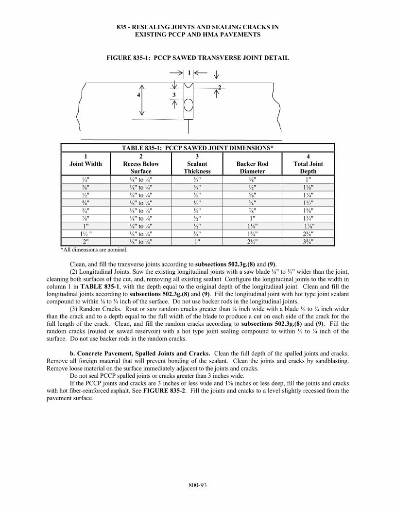
835 - RESEALING JOINTS AND SEALING CRACKS IN EXISTING PCCP AND HMA PAVEMENTS
800-93
FIGURE 835-1: PCCP SAWED TRANSVERSE JOINT DETAIL
1
2
4 3
TABLE 835-1: PCCP SAWED JOINT DIMENSIONS* 1
Joint Width 2
Recess Below Surface
3 Sealant
Thickness
Backer Rod
Diameter
4 Total Joint
Depth ¼" ⅛" to ¼" ⅜" ⅜" 1" ⅜" ⅛" to ¼" ⅜" ½" 1⅛" ½" ⅛" to ¼" ⅜" ⅝" 1¼" ⅝" ⅛" to ¼" ½" ¾" 1½" ¾" ⅛" to ¼" ½" ⅞" 1⅝" ⅞" ⅛" to ¼" ½" 1" 1¾" 1" ⅛" to ¼" ½" 1⅛" 1⅞"
1½ " ⅛" to ¼" ¾" 1¾" 2⅜" 2" ⅛" to ¼" 1" 2½" 3⅝"
*All dimensions are nominal. Clean, and fill the transverse joints according to subsections 502.3g.(8) and (9). (2) Longitudinal Joints. Saw the existing longitudinal joints with a saw blade ⅛" to ¼" wider than the joint, cleaning both surfaces of the cut, and, removing all existing sealant Configure the longitudinal joints to the width in column 1 in TABLE 835-1, with the depth equal to the original depth of the longitudinal joint. Clean and fill the longitudinal joints according to subsections 502.3g.(8) and (9). Fill the longitudinal joint with hot type joint sealant compound to within ⅛ to ¼ inch of the surface. Do not use backer rods in the longitudinal joints. (3) Random Cracks. Rout or saw random cracks greater than ⅛ inch wide with a blade ⅛ to ¼ inch wider than the crack and to a depth equal to the full width of the blade to produce a cut on each side of the crack for the full length of the crack. Clean, and fill the random cracks according to subsections 502.3g.(8) and (9). Fill the random cracks (routed or sawed reservoir) with a hot type joint sealing compound to within ⅛ to ¼ inch of the surface. Do not use backer rods in the random cracks. b. Concrete Pavement, Spalled Joints and Cracks. Clean the full depth of the spalled joints and cracks. Remove all foreign material that will prevent bonding of the sealant. Clean the joints and cracks by sandblasting. Remove loose material on the surface immediately adjacent to the joints and cracks. Do not seal PCCP spalled joints or cracks greater than 3 inches wide. If the PCCP joints and cracks are 3 inches or less wide and 1⅝ inches or less deep, fill the joints and cracks with hot fiber-reinforced asphalt. See FIGURE 835-2. Fill the joints and cracks to a level slightly recessed from the pavement surface.
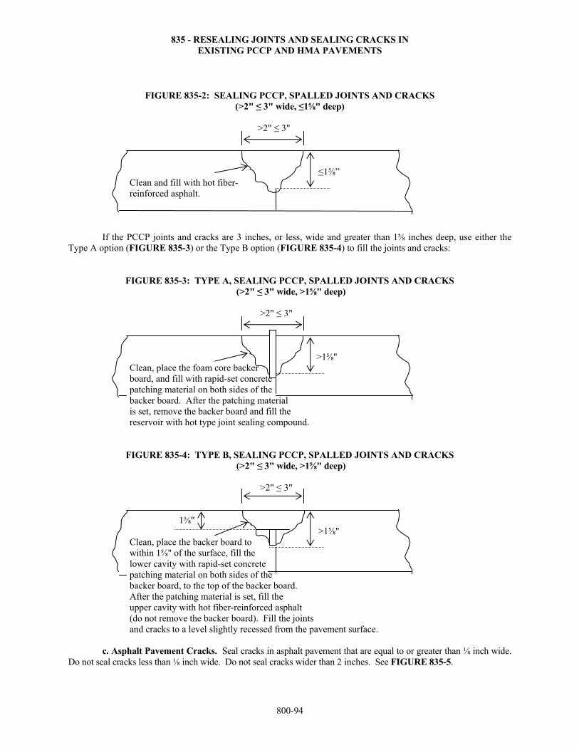
835 - RESEALING JOINTS AND SEALING CRACKS IN EXISTING PCCP AND HMA PAVEMENTS
800-94
FIGURE 835-2: SEALING PCCP, SPALLED JOINTS AND CRACKS (>2" ≤ 3" wide, ≤1⅝" deep)
>2" ≤ 3"
≤1⅝” Clean and fill with hot fiber- reinforced asphalt.
If the PCCP joints and cracks are 3 inches, or less, wide and greater than 1⅝ inches deep, use either the Type A option (FIGURE 835-3) or the Type B option (FIGURE 835-4) to fill the joints and cracks:
FIGURE 835-3: TYPE A, SEALING PCCP, SPALLED JOINTS AND CRACKS (>2" ≤ 3" wide, >1⅝" deep)
>2" ≤ 3"
>1⅝"
Clean, place the foam core backer board, and fill with rapid-set concrete patching material on both sides of the backer board. After the patching material is set, remove the backer board and fill the reservoir with hot type joint sealing compound.
FIGURE 835-4: TYPE B, SEALING PCCP, SPALLED JOINTS AND CRACKS (>2" ≤ 3" wide, >1⅝" deep)
>2" ≤ 3"
1⅝" >1⅝"
Clean, place the backer board to within 1⅝" of the surface, fill the lower cavity with rapid-set concrete patching material on both sides of the backer board, to the top of the backer board. After the patching material is set, fill the upper cavity with hot fiber-reinforced asphalt (do not remove the backer board). Fill the joints and cracks to a level slightly recessed from the pavement surface.
c. Asphalt Pavement Cracks. Seal cracks in asphalt pavement that are equal to or greater than ⅛ inch wide. Do not seal cracks less than ⅛ inch wide. Do not seal cracks wider than 2 inches. See FIGURE 835-5.
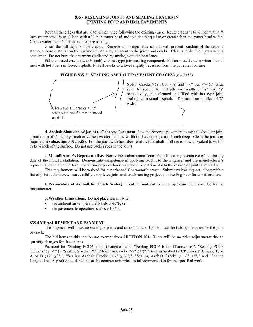
835 - RESEALING JOINTS AND SEALING CRACKS IN EXISTING PCCP AND HMA PAVEMENTS
800-95
Rout all the cracks that are ⅛ to ½ inch wide following the existing crack. Route cracks ⅛ to ⅜ inch with a ⅝ inch router head, ⅜ to ½ inch with a ¾ inch router head and to a depth equal to or greater than the router head width. Cracks wider than ½ inch do not require routing. Clean the full depth of the cracks. Remove all foreign material that will prevent bonding of the sealant. Remove loose material on the surface immediately adjacent to the joints and cracks. Clean and dry the cracks with a heat lance. Do not burn the pavement (indicated by smoke) with the heat lance. Fill the routed cracks (⅛ to ½ inch) with hot type joint sealing compound. Fill un-routed cracks wider than ½ inch with hot fiber-reinforced asphalt. Fill all cracks to a level slightly recessed from the pavement surface.
FIGURE 835-5: SEALING ASPHALT PAVEMENT CRACKS) (>⅛"<2") Note: Cracks >⅛", but <⅜" and >⅜" but </= ½" wide shall be routed to a depth and width of ⅝" and ¾" respectively, then cleaned and filled with hot type joint sealing compound asphalt. Do not rout cracks >1/2" wide.
Clean and fill cracks >1/2" wide with hot fiber-reinforced asphalt.
d. Asphalt Shoulder Adjacent to Concrete Pavement. Saw the concrete pavement to asphalt shoulder joint a minimum of ½ inch by 1inch or ⅛ inch greater than the width of the existing crack 1 inch deep Clean the joints as required in subsection 502.3g.(8). Fill the joint with hot fiber-reinforced asphalt. Fill the joint with sealant to within ⅛ to ¼ inch of the surface. Do not use backer rods in the joints.
e. Manufacturer’s Representative. Notify the sealant manufacturer’s technical representative of the starting
date of the initial installation. Demonstrate competence in applying sealant to the Engineer and the manufacturer’s representative. Do not perform operations or procedures that would be detrimental to the sealing of joints and cracks. This requirement will be waived for experienced Contractor’s crews. Submit waiver request, along with a list of joint sealant crews successfully completed joint and crack sealing projects, to the Engineer for consideration. f. Preparation of Asphalt for Crack Sealing. Heat the material to the temperature recommended by the manufacturer. g. Weather Limitations. Do not place sealant when:
the ambient air temperature is below 40F, or the pavement temperature is above 105F.
835.4 MEASUREMENT AND PAYMENT The Engineer will measure sealing of joints and random cracks by the linear foot along the center of the joint or crack.
The bid items in this section are exempt from SECTION 104. There will be no price adjustments due to quantity changes for these items. Payment for "Sealing PCCP Joints (Longitudinal)", "Sealing PCCP Joints (Transverse)", "Sealing PCCP Cracks (>⅛" <2")", "Sealing Spalled PCCP Joints & Cracks (>2" ≤3")", "Sealing Spalled PCCP Joints & Cracks, Type A or B (>2" ≤3")", "Sealing Asphalt Cracks (>⅛" ≤ ½")", "Sealing Asphalt Cracks (> ½" <2")" and "Sealing Longitudinal Asphalt Shoulder Joint" at the contract unit prices is full compensation for the specified work.
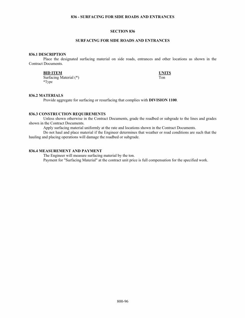
836 - SURFACING FOR SIDE ROADS AND ENTRANCES
800-96
SECTION 836
SURFACING FOR SIDE ROADS AND ENTRANCES 836.1 DESCRIPTION Place the designated surfacing material on side roads, entrances and other locations as shown in the Contract Documents. BID ITEM UNITS Surfacing Material (*) Ton *Type 836.2 MATERIALS Provide aggregate for surfacing or resurfacing that complies with DIVISION 1100. 836.3 CONSTRUCTION REQUIREMENTS Unless shown otherwise in the Contract Documents, grade the roadbed or subgrade to the lines and grades shown in the Contract Documents. Apply surfacing material uniformly at the rate and locations shown in the Contract Documents. Do not haul and place material if the Engineer determines that weather or road conditions are such that the hauling and placing operations will damage the roadbed or subgrade. 836.4 MEASUREMENT AND PAYMENT The Engineer will measure surfacing material by the ton. Payment for "Surfacing Material" at the contract unit price is full compensation for the specified work.
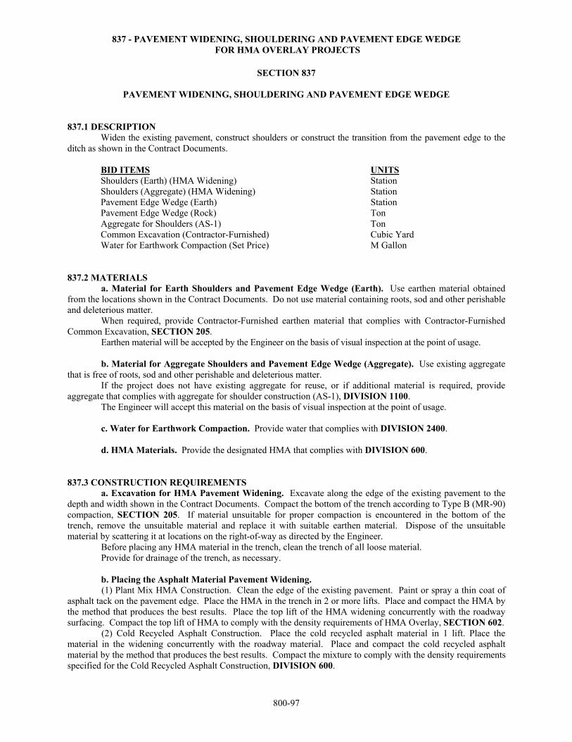
837 - PAVEMENT WIDENING, SHOULDERING AND PAVEMENT EDGE WEDGE FOR HMA OVERLAY PROJECTS
800-97
SECTION 837
PAVEMENT WIDENING, SHOULDERING AND PAVEMENT EDGE WEDGE 837.1 DESCRIPTION
Widen the existing pavement, construct shoulders or construct the transition from the pavement edge to the ditch as shown in the Contract Documents.
BID ITEMS UNITS Shoulders (Earth) (HMA Widening) Station Shoulders (Aggregate) (HMA Widening) Station Pavement Edge Wedge (Earth) Station Pavement Edge Wedge (Rock) Ton Aggregate for Shoulders (AS-1) Ton Common Excavation (Contractor-Furnished) Cubic Yard Water for Earthwork Compaction (Set Price) M Gallon
837.2 MATERIALS a. Material for Earth Shoulders and Pavement Edge Wedge (Earth). Use earthen material obtained from the locations shown in the Contract Documents. Do not use material containing roots, sod and other perishable and deleterious matter. When required, provide Contractor-Furnished earthen material that complies with Contractor-Furnished Common Excavation, SECTION 205.
Earthen material will be accepted by the Engineer on the basis of visual inspection at the point of usage.
b. Material for Aggregate Shoulders and Pavement Edge Wedge (Aggregate). Use existing aggregate that is free of roots, sod and other perishable and deleterious matter. If the project does not have existing aggregate for reuse, or if additional material is required, provide aggregate that complies with aggregate for shoulder construction (AS-1), DIVISION 1100. The Engineer will accept this material on the basis of visual inspection at the point of usage. c. Water for Earthwork Compaction. Provide water that complies with DIVISION 2400. d. HMA Materials. Provide the designated HMA that complies with DIVISION 600. 837.3 CONSTRUCTION REQUIREMENTS a. Excavation for HMA Pavement Widening. Excavate along the edge of the existing pavement to the depth and width shown in the Contract Documents. Compact the bottom of the trench according to Type B (MR-90) compaction, SECTION 205. If material unsuitable for proper compaction is encountered in the bottom of the trench, remove the unsuitable material and replace it with suitable earthen material. Dispose of the unsuitable material by scattering it at locations on the right-of-way as directed by the Engineer. Before placing any HMA material in the trench, clean the trench of all loose material. Provide for drainage of the trench, as necessary. b. Placing the Asphalt Material Pavement Widening.
(1) Plant Mix HMA Construction. Clean the edge of the existing pavement. Paint or spray a thin coat of asphalt tack on the pavement edge. Place the HMA in the trench in 2 or more lifts. Place and compact the HMA by the method that produces the best results. Place the top lift of the HMA widening concurrently with the roadway surfacing. Compact the top lift of HMA to comply with the density requirements of HMA Overlay, SECTION 602.
(2) Cold Recycled Asphalt Construction. Place the cold recycled asphalt material in 1 lift. Place the material in the widening concurrently with the roadway material. Place and compact the cold recycled asphalt material by the method that produces the best results. Compact the mixture to comply with the density requirements specified for the Cold Recycled Asphalt Construction, DIVISION 600.
837 - PAVEMENT WIDENING, SHOULDERING AND PAVEMENT EDGE WEDGE FOR HMA OVERLAY PROJECTS
800-98
c. Shouldering the Asphalt or Concrete Pavement Widening. After the surface course is in place, construct the shoulders as shown in the Contract Documents. Do not damage the pavement surfaces. Do not dump or mix material on the pavement surfaces. (1) Earth Shoulders. Use material obtained from the widening trench excavation, or Contractor-furnished material, if required, to construct the earthen shoulders. Dispose of excess earthen material (obtained from the widening trench excavation), if any, at locations on the right-of way as directed by the Engineer. Construct the earth shoulders according to SECTION 205. (2) Aggregate Shoulders. Use existing aggregate obtained from the project, or aggregate provided by the Contractor, when required, to construct the aggregate shoulders. Stockpile any excess aggregate (obtained from the widening trench excavation at locations shown in the Contract Documents or locations on the project as directed by the Engineer. Construct the aggregate shoulders according to SECTION 305, except the compaction shall comply with Type B compaction and MR-3-3 Moisture Content, SECTION 205. d. Earthen and Aggregate Pavement Edge Wedge. After the surface course is in place, construct edge wedges as shown in the Contract Documents. Do not damage the pavement surfaces. Do not dump or mix material on the pavement surfaces. Use the type of material indicated in the Contract Documents to construct the wedges.
Place the material for the pavement edge wedge in a uniform layer. The maximum compacted thickness of any layer of earthen or aggregate pavement edge wedge is 6 inches. If the thickness is greater than 6 inches, spread and compact the aggregate base in multiple lifts of equal thickness with a maximum lift thickness of 6 inches.
Compact the wedges to comply with Type B (MR-90) Compaction, SECTION 205. 837.4 MEASUREMENT AND PAYMENT The Engineer will measure shoulder for asphalt widenings on each side of the roadway by the station. The excavation for the asphalt widenings is not measured for separate payment. The HMA quantities for the HMA widenings are included in the roadway surfacing quantities. The Engineer will measure earth pavement edge wedge on each side of the roadway by the station. The Engineer will measure the aggregate pavement edge wedge by the ton. The Engineer will measure the aggregate for shoulders by the ton. The Engineer will measure Contractor-furnished common excavation according to SECTION 205. The Engineer will measure water for earthwork compaction according to SECTION 205. Payment for "Shoulders (Earth) (HMA Widening)", "Shoulders (Aggregate) (HMA Widening)", "Pavement Edge Wedge (Earth)", "Pavement Edge Wedge (Rock)", "Aggregate for Shoulders (AS-1)" and "Common Excavation (Contractor-Furnished)" at the contract unit prices, and for "Water for Earthwork Compaction" at the contract unit set price is full compensation for the specified work.
838 - GRINDING REHAB CONCRETE PAVEMENT
800-99
SECTION 838
GRINDING REHAB CONCRETE PAVEMENT 838.1 DESCRIPTION
Grind the existing concrete pavement roadway surface to eliminate joint faulting and restore cross slope drainage, surface texture and riding characteristics. BID ITEM UNITS Grinding Concrete Surface Square Yard 838.2 MATERIALS - None specified. 838.3 CONSTRUCTION REQUIREMENTS
a. Equipment. (1) Profilograph. Use a California type profilograph, prequalified by the Bureau of Construction and
Materials, to determine the pavement profile. If approved by the Bureau of Construction and Materials, other types of profilographs that produce results compatible to the California type profilograph may be used. If the profilograph has a mechanical recorder, provide a ProScan electronic scanner with motorized paper transport to reduce the trace. Use the motorized paper transport when scanning the profilograph traces. The Bureau of Construction and Materials can provide the information necessary for the Contractor to obtain a ProScan electronic scanner. If approved by the Bureau of Construction and Materials, other types of automated trace reduction equipment may be used. If the profilograph has a computerized recorder, the trace produced is evaluated without further reduction.
(2) Grinding Machine. Provide a self-propelled grinding machine specifically designed to grind and texture portland cement concrete pavement using diamond blades mounted on a multi-blade arbor.
The arbor must contain enough blades to provide at least a 36-inch wide cutting head and provide 55 to 60 evenly spaced grooves per foot.
Do not use equipment that causes excessive ravels, aggregate fractures or spalls. Use equipment that provides a flat plane surface without crown and a uniform texture for the full width of the lane. Grind a nominal depth of 3/16 inch. Transverse grooving is not required.
Use vacuum equipment or other continuous methods to remove grinding slurry and residue. Remove from the project and properly dispose of the material. Do not allow the grinding slurry to flow across lanes being used by traffic, onto shoulder slopes, into streams, lakes, ponds or other bodies of water, or gutters or other drainage facilities. Do not place grinding slurry on foreslopes.
Bush hammers or other impact devices are prohibited.
b. Profilograph Operation. Provide an operator for the profilograph certified according to KT-46, Part V. Determine the pavement profiles for each lane according to the procedures for 1 lane shown in Kansas Test
Method KT-46. Additional profiles may be taken only to define the limits of an out-of-tolerance surface variation. The Engineer may use a 10-foot straightedge (or other means) to detect irregularities outside the required trace paths. The Engineer may also use the straightedge to delineate the areas that require corrective action. A pavement section is a continuous area of pavement surface 0.1 mile long by 1 lane wide (12 feet nominal). A partial pavement section resulting from an interruption (such as a bridge) of the continuous pavement surface is subject to the same testing and evaluation as a whole section. On surfaces excluded from profilograph testing, the Engineer will determine the pavement smoothness using a 10-foot straightedge. The Engineer will select the locations to be tested. The variation of the surface from the testing edge of the straightedge shall not exceed ⅛ inch between any 2 contacts, longitudinal or transverse.
c. Finish Requirements. (1) Provide a control profilograph prior to performing any grinding work. This control trace will be used to
identify the required smoothness for the project. If other repairs are performed on the project prior to grinding, such as pavement patching, perform the control trace, prior to that construction commencing.
838 - GRINDING REHAB CONCRETE PAVEMENT
800-100
(2) Grind and texture the entire surface of the pavement in the longitudinal direction. Grind at least 95% of the surface area in each 100-foot section and both sides of the transverse joints and cracks in the same plane. Provide positive lateral drainage by maintaining a constant cross slope between grinding passes in each lane. Maintain a uniform transverse slope that matches the existing cross slope to the extent possible with no depressions or humps greater than 0.25 inch in 12 feet when tested with a string line or straightedge. Do not exceed by more than 0.0625 inch the vertical alignment between adjacent passes of the cutting head. Begin and end grinding lines normal to the direction of vehicle travel. Grind the surface so corrugations are parallel to the pavement edge with ridges 0.0625 inch, ±0.03125 inch higher than the valleys of the corrugations.
Finish-grind the surface so that each segment has a final profile index a maximum of 35% of the control profilograph trace or 30 inches per mile whichever is greater. Correct all deviations in excess of 0.30 inch in a length of 25 feet within each section regardless of the profile index value. (3) After completing the pavement grinding, profile the pavement with the same California type profilograph used to establish control profilograph trace. Run 2 traces in each corrected lane. Run a trace 36 inches from the longitudinal joint between the lanes, and another trace 36 inches from the shoulder edge of the lane. Determine a profile index in inches/mile for each section of corrected pavement surface. A pavement section is defined as a continuous area of finished pavement 0.1 mile in length and one 12-foot lane (nominal) in width. A partial section resulting from an interruption of the continuous pavement surface is subject to the same evaluation as a whole section. Within 2 days after the corrections to the roadway surface are made, provide the Engineer with the profilogram and its evaluation. (4) Perform additional grinding to attain the required profile index provided the maximum depth of removal does not exceed 0.75 inch. (5) The Engineer may perform profilograph testing on the surface for monitoring and comparison purposes. The Engineer may test the entire project length if determined the Contractor’s test results are inaccurate. If the Engineer performs profilograph testing on the project and determines the Contractor’s results are inaccurate, the Contractor will be charged $640.00 per mile per trace (minimum charge is $800.00).
(6) Correct all irregularities exceeding the specified tolerance using equipment and methods approved by the Engineer. After the irregularities are corrected, the Engineer will retest the area to verify compliance with the specified tolerance. 838.4 MEASUREMENT AND PAYMENT The Engineer will measure grinding of concrete pavement surface by the square yard. A Grinding Concrete Surface Smoothness pay adjustment per 0.1 mile section per lane will be based on the average of the profile index of the 2 traces per 0.1 mile section per lane. Payment will be made according to TABLE 838-1.
TABLE 838-1: SCHEDULE FOR ADJUSTING PAYMENT FOR GRINDING EXISTING PAVEMENT
Average Profile Index Inch per mile per 0.1 mile section
Contract Price Adjustment Per 0.1 mile section per lane
10.0 or less $135.00 10.1 to 15.0 $95.00 15.1 to 18.0 $50.00 18.1 to 30.0 0.00
Payment for "Grinding Concrete Surface" at the contract unit price is full compensation for the specified work. Payment for ″Grinding Concrete Surface Smoothness″ will be shown as an added item to the contract.
839 - RUBBLIZING PORTLAND CEMENT CONCRETE PAVEMENT
800-101
SECTION 839
RUBBLIZING PORTLAND CEMENT CONCRETE PAVEMENT 839.1 DESCRIPTION Rubblize the existing PCCP, and compact the broken PCCP in place as shown in the Contract Documents. BID ITEMS UNITS Crushed Stone for Backfill Cubic Yard Removal of Asphalt Material Square Yard Rubblized Concrete Square Yard 839.2 MATERIALS Provide crushed stone for backfill that complies with DIVISION 1100.
Provide HMA that complies with DIVISION 600. 839.3 CONSTRUCTION REQUIREMENTS Before starting the rubblizing of the PCCP, remove and dispose of all asphalt overlays and patches. Replace the asphalt patches with crushed stone for backfill. Use an impact hammer, resonant breaker or other equipment to break the pavement into the specified sizes without displacing the rubblized material into the base or subgrade. Use equipment capable of delivering enough energy to rubblize the PCCP. Where needed, use a breaker with a plate-type shoe designed to prevent penetration into the existing surface. Provide a watering system to suppress dust generated by the rubblizing operation. Provide a shield to prevent flying chips of pavement produced by the rubblizing operation. Rubblize the PCCP full depth and full panel width to produce broken reinforcement, or the loss of concrete to steel bond. The majority of the rubblized PCCP shall be:
12 inches or smaller in size, with 80 to 100% less than 12 inches. 95% of the fragments greater than 6 inches. The maximum size is 15 inches. Do not displace the concrete vertically (before rolling) more than ±1 inch.
Construct a test section to demonstrate compliance with the rubblizing specification. The Engineer will determine the location of the test section. Provide equipment to verify compliance with the sizing requirements. Vary the energy and striking patterns of the pavement breaker, and, when necessary, make repeated passes with the equipment until the specified rubblization is achieved.
Seat and uniformly compact the rubblized concrete. Use a steel wheel roller (10 tons) or a steel wheel vibratory roller to seat and compact the rubblized PCCP. Make a minimum of 2 one-way passes with the roller. Do not roll in a manner that will disperse the outside edge of the rubblized PCCP. Do not cause rutting, pumping or de-densification of the rubblized PCCP by over-compaction. If compaction is not achieved with the steel wheel roller, the Engineer may allow the use of a larger pneumatic roller.
The Engineer will determine, by visual inspection, if satisfactory rubblization is achieved. Use the procedures established in the test section to rubblize, seat and compact the existing PCCP. If
during the course of the work, the rubblizing requirements are not achieved, the Engineer may require another test section be constructed.
If soft spots are detected during the compaction operations, remove the unstable subgrade material and backfill with suitable material to the top of the subgrade. Fill from the subgrade to the top of the adjacent rubblized PCCP with crushed stone for backfill.
After the PCCP is rubblized and compacted, the Engineer may designate areas that require leveling. If the leveling course is placed directly on the rubblized and compacted PCCP, use either crushed stone for backfill or HMA base material. If HMA base material is used for leveling between succeeding lifts of the HMA base, complete the leveling before the final lift of the HMA base is placed. The material used for leveling (HMA or crushed stone for backfill) may be spread with a motor grader.

839 - RUBBLIZING PORTLAND CEMENT CONCRETE PAVEMENT
800-102
Overlay the rubblized and compacted PCCP with a HMA base course as soon as possible, within 24 hours of the rubblizing operations. If the rubblized PCCP is not covered with the HMA base within 24 hours, the Engineer will direct the Contractor to suspend all rubblizing operations until the previously rubblized PCCP is overlaid.
Do not allow traffic (other than necessary construction traffic) on the rubblized PCCP until a minimum of 4 inches of HMA base is placed on the rubblized PCCP. 839.4 MEASUREMENT AND PAYMENT The Engineer will measure the crushed stone for backfill by the cubic yard.
The Engineer will measure the removal of asphalt material by the square yard. The Engineer will measure rubblized PCCP by the square yard. The Engineer will measure the actual width of the existing PCCP, along the centerline of the roadway or ramp. Payment for "Crushed Stone for Backfill", "Removal of Asphalt Material" and "Rubblized Concrete" at the contract unit prices is full compensation for the specified work. Measurement and payment for HMA materials are as provided in the Contract Documents.
840 - TEMPORARY SURFACING
800-103
SECTION 840
TEMPORARY SURFACING 840.1 DESCRIPTION Place and maintain temporary surfacing material to provide temporary access (ingress and egress) for residences and places of businesses. Remove and dispose of material when no longer needed. BID ITEMS UNITS Temporary Surfacing Material (Aggregate) (Set Price) Cubic Yard Temporary Surfacing Material (HMA) (Set Price) Ton 840.2 MATERIALS Provide aggregate for temporary surfacing suitable for the intended purpose. The Engineer will accept the aggregate based on the performance of the material. Provide HMA for temporary surfacing that is a commercial mix in general use in the local area. Provide a mixture of materials from recognized producers, mixed in a recognized type of hot mix plant. Provide emulsified asphalt for tack, when necessary. The Engineer will accept the HMA based on performance of the material. 840.3 CONSTRUCTION REQUIREMENTS Place and spread the temporary surfacing material at the locations determined by the Engineer. Place and spread the temporary surfacing material to a smooth, reasonable cross-section. Shape the section to prevent ponding of water. When placing HMA, use recognized equipment and techniques to weigh, haul, spread and compact the mixture. Complete the compaction operations while the temperature of the mixture is above 175°F. Do not place HMA on wet or frozen surfaces, or when the weather conditions will prevent proper handling and finishing of the mixture. The Engineer may waive the weather limitations when warranted. Maintain the temporary surfacing to provide ingress and egress in all types of weather. Place additional material as necessary. Remove and dispose of the material when no longer necessary. 840.4 MEASUREMENT AND PAYMENT The Engineer will measure the aggregate temporary surfacing material by the cubic yard in the vehicle at the place of unloading. The Engineer will measure the HMA temporary surfacing material by the ton. The Engineer will accept commercial scale tickets completed by the producer of the material. Payment for "Temporary Surfacing Material (Aggregate) (Set Price)" and "Temporary Surfacing Material (HMA) (Set Price)" at the contract unit set prices is full compensation for the specified work. The contract unit set prices will govern regardless of the accepted quantity provided.
841 - LIGHT TYPE SURFACING
800-104
SECTION 841
LIGHT TYPE SURFACING 841.1 DESCRIPTION Haul the material shown in the Contract Documents to the roadway and windrow the material for surfacing. BID ITEM UNITS Light Type Surfacing (*) Cubic Yard *Type: SA-* or SS-* 841.2 MATERIALS Provide the specified type of aggregate that complies with DIVISION 1100. 841.3 CONSTRUCTION REQUIREMENTS When shown in the Contract Documents, prepare the embankment or subgrade as detailed in the Contract Documents. When not shown in the Contract Documents, others will prepare the embankment or subgrade. The rate of application for the light type surfacing is shown in the Contract Documents. Do not haul material to the road when weather or road conditions are such that the hauling operations will damage the roadbed or subgrade. Windrow the material hauled to the road along one shoulder of the road. Place the windrow on the roadway and parallel to the edge of the roadway, approximately 1 foot from the edge of the roadway or as directed by the Engineer. Construct a uniform windrow to a maximum width of 6 feet. When not shown in the Contract Documents, others will spread the light type surfacing. When shown in the Contract Documents, spread the light type surfacing to the dimensions shown in the Contract Documents. 841.4 MEASUREMENT AND PAYMENT The Engineer will measure the light type surfacing by the cubic yard. Payment for "Light Type Surfacing" at the contract unit price is full compensation for the specified work.
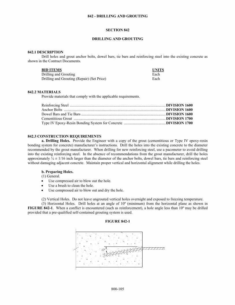
842 - DRILLING AND GROUTING
800-105
SECTION 842
DRILLING AND GROUTING 842.1 DESCRIPTION Drill holes and grout anchor bolts, dowel bars, tie bars and reinforcing steel into the existing concrete as shown in the Contract Documents. BID ITEMS UNITS Drilling and Grouting Each Drilling and Grouting (Repair) (Set Price) Each 842.2 MATERIALS
Provide materials that comply with the applicable requirements. Reinforcing Steel ................................................................................................... DIVISION 1600 Anchor Bolts ......................................................................................................... DIVISION 1600 Dowel Bars and Tie Bars ....................................................................................... DIVISION 1600 Cementitious Grout ............................................................................................... DIVISION 1700 Type IV Epoxy-Resin Bonding System for Concrete ........................................... DIVISION 1700
842.3 CONSTRUCTION REQUIREMENTS a. Drilling Holes. Provide the Engineer with a copy of the grout (cementitious or Type IV epoxy-resin bonding system for concrete) manufacturer’s instructions. Drill the holes into the existing concrete to the diameter recommended by the grout manufacturer. When drilling for new reinforcing steel, use a pacometer to avoid drilling into the existing reinforcing steel. In the absence of recommendations from the grout manufacturer, drill the holes approximately ¼ ± 1/16 inch larger than the diameter of the anchor bolts, dowel bars, tie bars and reinforcing steel without damaging adjacent concrete. Maintain proper vertical and horizontal alignment while drilling the holes. b. Preparing Holes. (1) General.
Use compressed air to blow out the hole. Use a brush to clean the hole. Use compressed air to blow out and dry the hole. (2) Vertical Holes. Do not leave ungrouted vertical holes overnight and exposed to freezing temperature.
(3) Horizontal Holes. Drill holes at an angle of 10º (minimum) from the horizontal plane as shown in FIGURE 842-1. When a conflict is encountered (such as reinforcement), a hole angle less than 10º may be drilled provided that a pre-qualified self-contained grouting system is used.
FIGURE 842-1
842 - DRILLING AND GROUTING
800-106
c. Grouting Holes. Mix, apply and cure the grout according to the manufacturer’s instructions. Fill the dry, clean holes with an approved grout. Insert the bolt, bar or reinforcing steel into the freshly grouted hole so that no voids exist between the bolt, bar or reinforcing steel and the concrete. Clean overflow and center the bar or bolt in the hole. d. Testing. When designated in the Contract Documents, proof load 20% of the installed anchorages to 90% of the design load according to the procedures in the Contract Documents. 842.4 MEASUREMENT AND PAYMENT The Engineer will not measure the drilling and grouting of bars and bolts that are included in other items of work (such as the erection of structural steel and concrete pavement patching). When shown as a bid item in the contract, the Engineer will measure each drilled and grouted hole. Payment for "Drilling and Grouting" at the contract unit price, and "Drilling and Grouting (Repair) (Set Price) at the contract unit set price, is full compensation for the specified work.
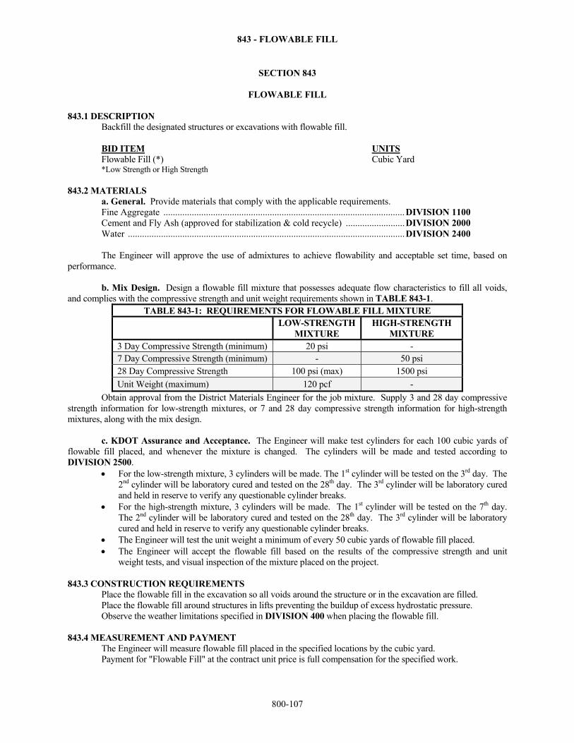
843 - FLOWABLE FILL
800-107
SECTION 843
FLOWABLE FILL 843.1 DESCRIPTION Backfill the designated structures or excavations with flowable fill. BID ITEM UNITS Flowable Fill (*) Cubic Yard *Low Strength or High Strength 843.2 MATERIALS
a. General. Provide materials that comply with the applicable requirements. Fine Aggregate ...................................................................................................... DIVISION 1100 Cement and Fly Ash (approved for stabilization & cold recycle) ......................... DIVISION 2000 Water ..................................................................................................................... DIVISION 2400
The Engineer will approve the use of admixtures to achieve flowability and acceptable set time, based on
performance. b. Mix Design. Design a flowable fill mixture that possesses adequate flow characteristics to fill all voids, and complies with the compressive strength and unit weight requirements shown in TABLE 843-1.
TABLE 843-1: REQUIREMENTS FOR FLOWABLE FILL MIXTURE
LOW-STRENGTH
MIXTURE HIGH-STRENGTH
MIXTURE 3 Day Compressive Strength (minimum) 20 psi - 7 Day Compressive Strength (minimum) - 50 psi 28 Day Compressive Strength 100 psi (max) 1500 psi
Unit Weight (maximum) 120 pcf -
Obtain approval from the District Materials Engineer for the job mixture. Supply 3 and 28 day compressive strength information for low-strength mixtures, or 7 and 28 day compressive strength information for high-strength mixtures, along with the mix design. c. KDOT Assurance and Acceptance. The Engineer will make test cylinders for each 100 cubic yards of flowable fill placed, and whenever the mixture is changed. The cylinders will be made and tested according to DIVISION 2500.
For the low-strength mixture, 3 cylinders will be made. The 1st cylinder will be tested on the 3rd day. The 2nd cylinder will be laboratory cured and tested on the 28th day. The 3rd cylinder will be laboratory cured and held in reserve to verify any questionable cylinder breaks.
For the high-strength mixture, 3 cylinders will be made. The 1st cylinder will be tested on the 7th day. The 2nd cylinder will be laboratory cured and tested on the 28th day. The 3rd cylinder will be laboratory cured and held in reserve to verify any questionable cylinder breaks.
The Engineer will test the unit weight a minimum of every 50 cubic yards of flowable fill placed. The Engineer will accept the flowable fill based on the results of the compressive strength and unit
weight tests, and visual inspection of the mixture placed on the project. 843.3 CONSTRUCTION REQUIREMENTS Place the flowable fill in the excavation so all voids around the structure or in the excavation are filled. Place the flowable fill around structures in lifts preventing the buildup of excess hydrostatic pressure.
Observe the weather limitations specified in DIVISION 400 when placing the flowable fill. 843.4 MEASUREMENT AND PAYMENT The Engineer will measure flowable fill placed in the specified locations by the cubic yard.
Payment for "Flowable Fill" at the contract unit price is full compensation for the specified work.
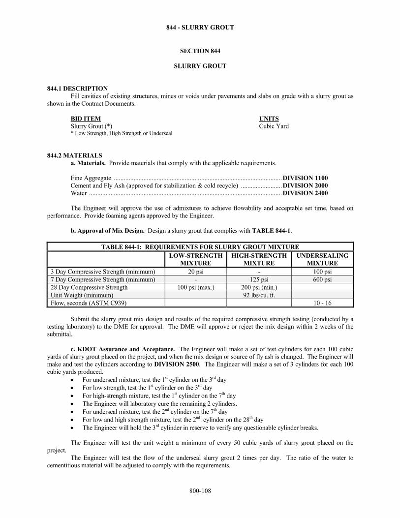
844 - SLURRY GROUT
800-108
SECTION 844
SLURRY GROUT 844.1 DESCRIPTION Fill cavities of existing structures, mines or voids under pavements and slabs on grade with a slurry grout as shown in the Contract Documents. BID ITEM UNITS Slurry Grout (*) Cubic Yard * Low Strength, High Strength or Underseal 844.2 MATERIALS
a. Materials. Provide materials that comply with the applicable requirements.
Fine Aggregate ...................................................................................................... DIVISION 1100 Cement and Fly Ash (approved for stabilization & cold recycle) ......................... DIVISION 2000 Water ..................................................................................................................... DIVISION 2400
The Engineer will approve the use of admixtures to achieve flowability and acceptable set time, based on
performance. Provide foaming agents approved by the Engineer.
b. Approval of Mix Design. Design a slurry grout that complies with TABLE 844-1.
TABLE 844-1: REQUIREMENTS FOR SLURRY GROUT MIXTURE LOW-STRENGTH
MIXTURE HIGH-STRENGTH
MIXTURE UNDERSEALING
MIXTURE 3 Day Compressive Strength (minimum) 20 psi - 100 psi 7 Day Compressive Strength (minimum) - 125 psi 600 psi 28 Day Compressive Strength 100 psi (max.) 200 psi (min.) Unit Weight (minimum) 92 lbs/cu. ft. Flow, seconds (ASTM C939) 10 - 16
Submit the slurry grout mix design and results of the required compressive strength testing (conducted by a
testing laboratory) to the DME for approval. The DME will approve or reject the mix design within 2 weeks of the submittal. c. KDOT Assurance and Acceptance. The Engineer will make a set of test cylinders for each 100 cubic yards of slurry grout placed on the project, and when the mix design or source of fly ash is changed. The Engineer will make and test the cylinders according to DIVISION 2500. The Engineer will make a set of 3 cylinders for each 100 cubic yards produced.
For underseal mixture, test the 1st cylinder on the 3rd day For low strength, test the 1st cylinder on the 3rd day For high-strength mixture, test the 1st cylinder on the 7th day The Engineer will laboratory cure the remaining 2 cylinders. For underseal mixture, test the 2nd cylinder on the 7th day For low and high strength mixture, test the 2nd cylinder on the 28th day The Engineer will hold the 3rd cylinder in reserve to verify any questionable cylinder breaks.
The Engineer will test the unit weight a minimum of every 50 cubic yards of slurry grout placed on the project. The Engineer will test the flow of the underseal slurry grout 2 times per day. The ratio of the water to cementitious material will be adjusted to comply with the requirements.
844 - SLURRY GROUT
800-109
The Engineer will accept the slurry grout based on the results of the compressive strength, unit weight tests, and visual inspection of the mixture placed on the project. 844.3 CONSTRUCTION REQUIREMENTS Pump the slurry grout into the structures to fill all the voids. Bulkhead each end of the structure to be filled. Provide a minimum of 2 vent pipes to monitor the pumping. If necessary to fill the structure, pump additional grout through the vent pipes. If filling voids under pavements and slabs on grade, place the slurry grout as shown on the Contract Documents. Observe the weather limitations specified in DIVISION 400 when placing the slurry grout. 844.4 MEASUREMENT AND PAYMENT The Engineer will measure slurry grout by the cubic yard.
Payment for "Slurry Grout" at the contract unit price is full compensation for the specified work.
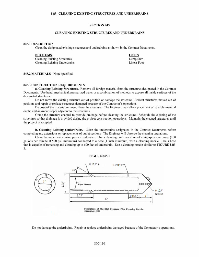
845 - CLEANING EXISTING STRUCTURES AND UNDERDRAINS
800-110
SECTION 845
CLEANING EXISTING STRUCTURES AND UNDERDRAINS 845.1 DESCRIPTION Clean the designated existing structures and underdrains as shown in the Contract Documents. BID ITEMS UNITS Cleaning Existing Structures Lump Sum Cleaning Existing Underdrains Linear Foot 845.2 MATERIALS - None specified. 845.3 CONSTRUCTION REQUIREMENTS a. Cleaning Existing Structures. Remove all foreign material from the structures designated in the Contract Documents. Use hand, mechanical, pressurized water or a combination of methods to expose all inside surfaces of the designated structures. Do not move the existing structure out of position or damage the structure. Correct structures moved out of position, and repair or replace structures damaged because of the Contractor’s operations. Dispose of the material removed from the structure. The Engineer may allow placement of suitable material on the embankment slopes adjacent to the structures. Grade the structure channel to provide drainage before cleaning the structure. Schedule the cleaning of the structures so that drainage is provided during the project construction operations. Maintain the cleaned structures until the project is accepted. b. Cleaning Existing Underdrains. Clean the underdrains designated in the Contract Documents before completing any extensions or replacements of outlet sections. The Engineer will observe the cleaning operations. Clean the underdrains using pressurized water. Use a cleaning unit consisting of a high-pressure pump (100 gallons per minute at 500 psi, minimum) connected to a hose (1 inch minimum) with a cleaning nozzle. Use a hose that is capable of traversing and cleaning up to 600 feet of underdrain. Use a cleaning nozzle similar to FIGURE 845-1.
FIGURE 845-1
Do not damage the underdrains. Repair or replace underdrains damaged because of the Contractor’s operations.
845 - CLEANING EXISTING STRUCTURES AND UNDERDRAINS
800-111
c. Video Inspection of Cleaned Underdrains. In the presence of the Engineer, perform a video inspection of all underdrains shown in the Contract Documents.
For the video inspection, provide a video camera complying with the following requirements: high resolution, high sensitivity, waterproof and color; capable of negotiating the various angle fittings used in the edge drain system; with sufficient lighting to provide a true color picture of the entire periphery of the diameter of the
pipe; and with attachments that will maintain the camera’s position in the center of the pipe.
Provide a portable control unit of the video camera complying with the following requirements: capable of adjusting the iris, focus, and light level intensity; have a color monitor (8 inch minimum) to track the camera’s progress through the inspections; have 2 video input/output jacks for video recording, as well as tape playback verification through the
built-in monitor; and have audio input to allow for dubbing of the video to incorporate comments as necessary. Provide a video camera system complying with the following requirements: have sufficient cable/push rod to conduct inspections to a length of 500 feet, and a distance counter to
monitor the length of the inspection; have a color video printer that will produce color prints of any observations of interest during the
course of the inspection; and include a video recorder (minimum quality 4-head industrial grade VHS type) with audio dubbing, still
frame and slow speed capabilities.
Provide an experienced video technician to operate the video camera system. Using the same equipment noted above, re-clean any underdrains found to still contain soils and not working as intended.
Acceptance by the Engineer of the cleaned underdrain will be based on observations made during the video inspection. 845.4 MEASUREMENT AND PAYMENT The Engineer will measure cleaning of the designated structures by the lump sum. The Engineer will measure cleaning of the designated underdrains by the linear foot. The Engineer will measure the length of hose and nozzle inserted into the underdrain. Payment for "Cleaning Existing Structures" and "Cleaning Existing Underdrains" at the contract unit prices is full compensation for the specified work.
846 - TRANSPORTING SALVAGEABLE MATERIAL
800-112
SECTION 846
TRANSPORTING SALVAGEABLE MATERIAL 846.1 DESCRIPTION Transport salvaged material to locations either on or off the project as shown in the Contract Documents. BID ITEM UNITS Transporting Salvageable Material * * Unit of Measurement shown in the Contract Documents 846.2 MATERIALS - None specified. 846.3 CONSTRUCTION REQUIREMENTS Transport the salvaged materials to the locations designated in the Contract Documents. Do not damage the salvaged material while loading, transporting and unloading at the storage area. When the Contractor damages material designated as salvage, 60% of the current quoted price for new material delivered to the project will be charged to the Contractor. This amount will be deducted from payments due the Contractor. 846.4 MEASUREMENT AND PAYMENT The Engineer will measure transportation of salvaged material by the units shown in the Contract Documents. Payment for "Transporting Salvageable Material" at the contract unit price is full compensation for the specified work.
847 - MAILBOX ADJUSTMENTS
800-113
SECTION 847
MAILBOX ADJUSTMENTS 847.1 DESCRIPTION Remove existing mailboxes and mailbox supports. When required by construction sequencing, relocate mailboxes at locations agreeable to owner and U.S. Postal Service. Reinstall acceptable mailboxes and mailbox supports. BID ITEM UNITS Mailbox Installation (Set Price) Each 847.2 MATERIALS When necessary, provide commercially available mailbox supports constructed of a single 4-inch by 4-inch wooden post, a single 4-inch diameter wooden post or a single metal post. Use metal posts with a maximum strength of a 2-inch diameter standard strength steel pipe. Anti-twist devices (that extend a maximum of 10 inches below ground) are permitted on metal posts. Anchor plates are prohibited on metal posts. Provide commercially available post-to-mailbox assemblies. The Engineer will accept the mailbox supports and post-to-mailbox assemblies based on compliance with the specified requirements and visual inspection for condition at the point of usage. 847.3 CONSTRUCTION REQUIREMENTS Remove the existing mailboxes and supports, and lay the mailboxes and supports on the owner’s property. The Engineer will inform the mailbox owners that only mailboxes and mailbox supports that comply with the requirements of the U.S. Postal Service will be reinstalled. If the owner’s mailbox is unacceptable, it is the owner’s responsibility to provide an acceptable mailbox for reinstallation. If the owner’s mailbox support is unacceptable, the Contractor will provide an acceptable mailbox support for reinstallation. The Contractor will reinstall the mailbox owner’s original mailbox if said mailbox complies with U.S. Post Office requirements. If the mailbox owner provides a lightweight newspaper delivery box, the Contractor will install the newspaper box below the mailbox (on the side of the mailbox support) when the mailbox is reinstalled. If the mailbox owner chooses to reinstall their own mailbox, the Engineer will inform the owner of highway permit procedures, and advise the owner that the reinstallation must be approved by KDOT. When the mailboxes are reinstalled, use these guidelines for installation:
Locate the mailboxes on the right-hand side of the roadway in the direction of the delivery route. Mailboxes may be located on the left-hand side of the roadway on one-way streets.
Embed the mailbox support post into the ground a maximum of 24 inches. Do not embed the post in concrete unless the mailbox support design is shown to be NCHRP 350 compliant when so installed.
Set the mailbox according to the Mailbox Guidelines established by the U.S. Postal Service. If there is a question as to the proper location of the mailbox, contact the U.S. Postal Service (local
Post Office) for guidance.
For roads not on the state highway system, e.g, roads under city, county or township jurisdiction, the mailbox offset may be less than the distances outlined above and will be determined on a case-by-case basis in consultation with the owner of the facility. Items to be considered include, but are not limited to, roadway width, shoulder width, traffic volumes, presence of sight distance constraints, right of way impacts, etc.
847.4 MEASUREMENT AND PAYMENT The Engineer will measure each mailbox installation. The Engineer will not measure for separate payment temporary mailbox relocations required due to construction sequencing. Payment for "Mailbox Installation (Set Price)" at the contract unit set price is full compensation for the specified work.
848 – ANTI-GRAFFITTI COATING
800-114
SECTION 848
ANTI-GRAFFITI COATING 848.1 DESCRIPTION Prepare and apply the anti-graffiti coating to the surfaces to be protected, as designated in the Contract Documents. BID ITEM UNITS Anti-Graffiti Coating Square Yard Note: If this bid item is not included in the Contract Documents, this work is subsidiary to other items in the contract. 848.2 MATERIAL REQUIREMENTS Provide anti-graffiti coating that complies with DIVISION 1700. 848.3 CONSTRUCTION REQUIREMENTS Provide copies of the manufacturer’s material safety and technical data sheets. The technical data must include detailed application instructions, minimum and maximum application temperatures and recommended time between coats. Prepare the surfaces that will receive the anti-graffiti coating in accordance with the manufacturer’s recommendations before applying the coating. Store, mix, apply and cure the anti-graffiti coating as recommended by the manufacturer. 848.4 MEASUREMENT AND PAYMENT When shown as a bid item in the contract, the Engineer will measure the anti-graffiti coating by the square yard. If the anti-graffiti work is shown in the Contract Documents, but the bid item for this work is not included in the Contract Documents, the Engineer will not measure the anti-graffiti coating for separate payment. Payment for "Anti-Graffiti Coating" at the contract unit price is full compensation for the specified work.

849 – GEOMEMBRANE
800-115
SECTION 849
GEOMEMBRANE 849.1 DESCRIPTION Place geomembrane to form an impermeable barrier at the locations designated in the Contract Documents. BID ITEM UNITS Geomembrane Square Yard Note: If this bid item is not included in the Contract Documents, this work is subsidiary to other items in the contract. 849.2 MATERIALS Provide materials that comply with the applicable requirements.
Geomembrane ....................................................................................................... DIVISION 1700 Cushioning material FA-A ..................................................................................... DIVISION 1100
849.3 CONSTRUCTION REQUIREMENTS Do not remove the geomembrane from its package and expose it to sunlight or the elements more than 10 days before it is placed and covered. Place the geomembrane as shown in the Contract Documents, with the longitudinal axis of the roll perpendicular to the centerline of the roadway. Overlap the geomembrane with a minimum of 24 inches at the joints, with the uphill layer placed on top of the downhill layer of geomembrane. If the geomembrane is damaged by tears, punctures, or contamination from hydrocarbon spill, do not patch the damaged areas, replace the entire section of the geomembrane. Place the cushioning material (sand) in a manner that does not puncture or tear the geomembrane. 849.4 MEASUREMENT AND PAYMENT When shown as a bid item in the contract, the Engineer will measure the geomembrane by the square yard. If the geomembrane work is shown in the Contract Documents, but the bid item for this work is not included in the Contract Documents, the Engineer will not measure the geomembrane for separate payment. Quantities shown in the Contract Documents are based on the width of select granular backfill plus 6 feet for wrapping. Payment for "Geomembrane" at the contract unit price is full compensation for the specified work.
850 – GEOMEMBRANE
800-116
SECTION 850
SEPARATION GEOTEXTILE 850.1 DESCRIPTION Install the separation geotextile at the locations designated in the Contract Documents. BID ITEM UNITS Separation Geotextile Square Yard 850.2 MATERIALS Provide a non-woven geotextile that complies with SECTION 1710 and is contained on PQL-48 as a Class 1 geotextile. 850.3 CONSTRUCTION REQUIREMENTS Place the separation geotextile as shown in the Contract Documents. Overlap the geotextile a minimum of 10 inches. Place the initial lift of backfill 12 to 24 inches thick (loose measurement) so the construction traffic is not directly upon the separation geotextile. 850.4 MEASUREMENT AND PAYMENT The Engineer will measure the separation geotextile by the square yard. Material placed beyond the neat lines indicated in the Contract Documents is not measured for payment unless authorized by the Engineer. Payment for "Separation Geotextile" at the contract unit price is full compensation for the specified work.
851 – PAVEMENT WATERPROOFING MEMBRANE
800-117
SECTION 851
PAVEMENT WATERPROOFING MEMBRANE 851.1 DESCRIPTION Install the pavement waterproofing membrane at the locations designated in the Contract Documents. This product is primarily used over localized pavement failures, over joints and cracks, and on bridge decks before an overlay. BID ITEMS UNITS Pavement Waterproofing Membrane Square Yard
Pavement Waterproofing Membrane (*) Linear Foot * width 851.2 MATERIALS Provide pavement waterproofing membrane that meets DIVISION 1700. When the unit of measure is square yards, the minimum width of material is 36 inches. When the unit of measure is linear foot, the width of material is that specified in the Contract Documents. 851.3 CONSTRUCTION REQUIREMENTS Provide the Project Engineer with a copy of the fabric manufacturer’s recommendations for installation. Before placing the pavement waterproofing membrane, clean the existing pavement or bridge deck of any dirt, debris or deteriorating pavement materials, according to the manufacturer’s recommendations. Clean milled surfaces with compressed air to remove all dust and files.
Before placing the pavement waterproofing membrane on existing pavement, fill all holes and cracks wider than ½ inch in the existing pavement with approved crack filler. Remove and fill spalled areas greater than 3 inches in width with hot/cold-mix asphalt or a suitable crack filler. Before placing the pavement waterproofing membrane on an existing bridge deck, if necessary, place concrete patches on the existing bridge deck according to the details in the Contract Documents. Do not place the pavement waterproofing membrane unless the ambient and pavement temperatures are at least 50°F and rising. The pavement surface or bridge deck must be dry prior to installation. Apply a prime coat (at the rate recommended by the manufacturer of the fabric) when recommended by the fabric manufacturer. In addition, apply a prime coat on the existing pavement if the surface has been milled, if the dry pavement temperature is below 70ºF, or if the application is on a bridge deck. Place the pavement waterproofing membrane according to the manufacturer’s recommendations. Overlap the pavement waterproofing membrane joints as recommended by the fabric manufacturer.
When possible, construct the succeeding overlay as soon as recommended by the manufacturer, without allowing any traffic on the membrane.
When the succeeding overlay can not be immediately placed, open the roadway to traffic as recommended by the manufacturer. Construct the succeeding overlay within 10 calendar days of placing the pavement waterproofing membrane. On slopes greater than 5%, construct the overlay within 48 hours. Remove and replace all pavement waterproofing membrane that is damaged before it is covered with the overlay. 851.4 MEASUREMENT AND PAYMENT When the unit of measure specified in the Contract Documents is linear foot, the Engineer will measure each individual strip of pavement waterproofing membrane placed by the linear foot.
When the unit of measure specified in the Contract Documents is square yard, the Engineer will measure the pavement waterproofing membrane by the square yard. Payment for "Pavement Waterproofing Membrane" at the contract unit price is full compensation for the specified work.
852 – PAVING FABRIC
800-118
SECTION 852
PAVING FABRIC 852.1 DESCRIPTION Install the paving fabric at the locations designated in the Contract Documents and according to the manufacturer’s instructions. Minimum overlay thickness of 2 inches above the fabric is recommended. BID ITEM UNITS Paving Fabric Square Yard Tack (Paving Fabric) Ton 852.2 MATERIALS Provide a paving fabric that complies with SECTION 1710 and is contained on PQL-48 as a Paving Fabric. Protect the paving fabric from wetness during storage and transportation. Elevate the product above the ground and cover and protect from ultraviolet radiation, sunlight, strong acids or strong bases, and fire or flames. Provide PG 70-22, PG 67-22, PG 64-22, PG 58-10 or PG 58-28 for tack that meets DIVISION 1200. 852.3 CONSTRUCTION REQUIREMENTS
a. General. Provide the Engineer with a copy of the paving fabric manufacturer’s installation instructions.
b. Surface Preparation. Power broom, sweep or vacuum the pavement before installing the pavement fabric. The pavement surface should be dry, free of dirt, oil, and loose aggregate, prior to installation. c. Asphalt Tack. Apply the asphalt tack according to the paving fabric manufacturer’s instructions.
d. Paving Fabric Installation. Install the clean, dry paving fabric with the untreated side placed into the asphalt tack according to the manufacturer’s requirements. Overlap the paving fabric a minimum of 4 inches. Transverse overlaps should run in the direction of the paving operation. Tack all overlaps together.
Repair any wrinkles 1 inch or larger, by slitting and lapping in the direction of paving, and pressed down into the tack coat.
Turning of paving equipment, trucks, or other vehicles on the paving fabric must be gradual and kept to a minimum. Do not park vehicles on the paving fabric.
e. HMA Overlay. Do not exceed 24 hours between the time the fabric is placed and the next lift of HMA
is placed.
852.4 MEASUREMENT AND PAYMENT The Engineer will measure the paving fabric by the square yard. Material placed beyond the neat lines indicated in the Contract Documents is not measured for payment unless authorized by the Engineer.
The Engineer will measure tack (paving fabric) by the ton. Payment for "Paving Fabric" and "Tack (Paving Fabric)" at the contract unit prices is full compensation for the specified work.
853 – RETAINING WALL SYSTEM
800-119
SECTION 853
RETAINING WALL SYSTEM 853.1 DESCRIPTION The scope of work for wall erection includes; excavation, grading, and compaction of the wall foundation, general and local dewatering as required for proper execution of the work, construction of leveling pads, erection of precast panels or modular block wall elements, placement of soil reinforcing, and placement and compaction of select backfill material within the reinforced soil volume. The scope of work also includes providing and placing cast-in-place concrete coping. Include in the wall foundation all area underlying the leveling pad and the reinforced soil volume. BID ITEM UNITS Retaining Wall (*) Square Foot
*Type 853.2 MATERIALS a. General. Provide the complete retaining wall system (engineering design, geogrid, MBW, MSEW precast panels, reinforcing mesh and attachment device, joint filler, and all necessary accessories) from an approved manufacturer in accordance with the acceptable alternates for each particular structure as listed in the Contract Documents. The Bureau of Construction and Materials will maintain a list of approved systems. Products will remain on the prequalified list as long as Field Performance is satisfactory. b. Retaining Wall System.
(1) Concrete. Use cement complying with DIVISION 2000. Use air entrained concrete with a minimum compressive strength at 28 days of 4000 psi. Retarding admixtures may be used with prior approval of the Engineer. Accelerating agents or any admixture containing chlorides are prohibited.
Provide the MBW elements with a maximum absorption rate of 5% by weight and a minimum face shell thickness of 2 inch and complies with ASTM C1372.
For SSL MSE PLUS face panel 6 inches thick, provide a minimum compressive strength at 28 days of 4000 psi and is normally connected to a W8, W11, W15, W20, and W24 longitudinal wire.
Set in place void formers, tie strips, PVC sleeves, reinforcing steel, laps, galvanized reinforcing mesh, connecting pins, or lifting devices to the dimensions and tolerances shown on the shop plans prior to casting.
(2) Testing and Inspection. MSEW precast panel units will be accepted on the basis of compression tests and visual inspection. The compression testing and sampling for MBW will comply with ASTM C 140-91, Sampling and Testing Concrete Masonry Units, except as noted elsewhere in this specification. The MSEW precast panel units or MBW will be considered acceptable, regardless of curing age, if compression test results comply with the 28-day strength specifications, and if the visual inspection is satisfactorily completed. Provide facilities and perform all necessary sampling and testing. Notify the Engineer a minimum of one week in advance so that he may be present during all sampling and testing.
(3) Casting. Cast the MSEW precast panels in metal forms on a flat area, the front face at the bottom, the back face at the top. Set embed loops, void formers, or connectors in the rear face. Place the concrete in each form without interruption and consolidate by the use of an approved vibrator, supplemented by such hand tamping as may be necessary to force the concrete into the corners of the forms and prevent the formation of stone pockets or cleavage planes. Use clear form oil of the same manufacture throughout the casting operation. Cast the MBWs in a standard manner acceptable to the National Concrete Masonry Association and in accordance with the testing and inspection.
(4) Curing. Cure the MSEW precast panels in compliance with SECTION 710 for the concrete to develop the specified compressive strength. Cure the MBW units in a manner acceptable to the National Concrete Masonry Association. Any production lot which does not comply with subsection 853.2b.(1), Compressive Strength, will be rejected.
(5) Removal of Forms. Do not remove the forms until they can be removed without damage to the unit.
853 – RETAINING WALL SYSTEM
800-120
(6) Finish. Finish the front face of MSEW precast panel units in a formed finish complying with DIVISION 700 and approved by the Engineer. Finish the MBW as specified in the Contract Documents. Screed the rear face of the MSEW precast panel or the non-exposed faces of the MBW to eliminate open pockets of aggregate and surface distortions in excess of 1/4 inch.
(7) Tolerances. MSEW Precast Panel: Manufacture all units within the following tolerances: Dimensions: Lateral position of tie strips, within 1 inch. All other dimensions, within 3/16 inch. Squareness: As determined by the difference between the two diagonals, not exceeding ½ inch. Surface defects of formed surfaces measured on a length of 5 feet: not exceeding 1/8 inch.
MBW: Manufacture all units within 1/8 inch of the length and width plan dimension. Manufacture the units within 1/16 inch of the specified height and connection slots within 3/16 inch of plan dimension. Provide MBW units with a minimum of: 1.0 sq ft of face area each for full units. 0.5 sq ft of face area for each cap unit.
Provide a MBW system with angled sides capable of concave or convex alignment curves with minimum
radius of 4.5 to 6 feet. (8) Compressive Strength. Acceptance of the concrete MSEW precast panels or MBW with respect to compressive strength will be determined on a production lot basis. A lot consists of each 40 production panels or 10,000 production blocks or fraction thereof produced in 1 day. MSEW: Prepare a minimum of 6 standard 6 x 12-inch cylinders from samples selected at random from concrete used in the production lot and in accordance with Kansas Test Methods. Cure 3 cylinders in accordance with Kansas Test Methods and test at 28 days. Cure at least 3 of the cylinders in the same manner as the panels and test at 7 days or later. Additional sets of 3 cylinders cured in the same manner as the panels may be tested at other dates beginning at 7 days. A test result will be the average compressive strength of a set of cylinders. Acceptance of the lot will be made if the average of any set of 3 is greater than 4,000 psi and no single cylinder has a compressive strength less than 3600 psi. MBW: Select no less than 3 units at random from each lot to represent the production lot. Acceptance of the lot for compressive strength will be made if the average of any set of 3 is greater than 4000 psi and no single unit has a compressive strength less than 3600 psi.
(9) Rejection. Units will be rejected because of failure to comply as specified above, or any of the following defects:
Defects that indicate imperfect molding Honeycombed or open texture concrete surfaces Any damage that would prevent making a satisfactory joint Chipped facing panel/unit edges Discolored panels or blocks beyond reasonable variances in the opinion of the Engineer. (10) Marking. MSEW Precast Panel: Prominently scribe the date of manufacture on the rear face of each panel. MBW: Prominently display the date of manufacture and lot number on each production lot stored at the
casting plant in a manner acceptable to the Engineer. (11) Handling, Storage, and Shipping. Handle, store and ship all units in a manner as to eliminate the danger of staining, chipping, cracks, fractures, and excessive bending stresses. Support blocks or panels in storage on firm foundations in a manner that will protect the exposed exterior finish.
(12) Basis of Acceptance. The Retaining Wall System will be accepted on the basis of satisfactory results of materials test, compliance with dimensional requirements and visual inspection at the point of usage. c. Backfill. Provide aggregates for backfill complying with DIVISION 1100.
d. Concrete for Leveling Pads. Provide the following: Leveling pads. Commercial Grade (AE) concrete complying with SECTIONS 401, 402 and 1102.
853 – RETAINING WALL SYSTEM
800-121
e. Coping. Provide the following: Cast-in-Place copings. Grade 3.0 (AE) concrete complying with SECTIONS 401, 402 and 1102. Pre-cast Cap Blocks for MBW. Meet the requirements of subsection 853.2b. of this specification.
f. Soil Reinforcing. Use soil reinforcing shown in the Contract Documents. (1) Reinforcing Strips and Tie Strips. (Reinforced Earth Company) Use tie strips of shop fabricated hot rolled steel that complies with the minimum requirements of ASTM A570, Grade 50, or equivalent. Use reinforcing strips that complies with the following:
hot rolled from bars to the required shape and dimensions. Physical and mechanical properties that complies with ASTM A572, Grade 65, or equivalent. Cut to lengths and tolerances shown in the Contract Documents. Punch holes for bolts in the locations shown.
Galvanize the reinforcing and tie strips to comply to ASTM A123 after fabrication is completed. Inspect all reinforcing and tie strips so that they are true to size and free from defects that may impair their strength and durability. The reinforcing and tie strips will be accepted on the basis of a Type A Certification and visual inspection. (2) Soil Reinforcing Mesh. Provide shop fabricated reinforcing mesh of cold drawn steel wire complying with the minimum requirements of ASTM A82 and weld into the finished mesh fabric in accordance with ASTM A185. Form loops or weld connection plates so the variation in length between the longest and the shortest longitudinal wire in a reinforcing mesh panel is no more than 1/8 inch when measured from the cross-wire nearest the end of the reinforcing mesh panel. Loop fabrication must permit a 5/8 inch diameter rod to pass through all loops on each piece of mesh. Galvanize reinforcing mesh in accordance with ASTM A123. The mesh will be accepted on the basis of a Type A Certification and visual inspection. (3) Soil Reinforcing Geogrid. Use soil reinforcing geogrid of oriented, drawn, long chain high density polyethylene or polypropylene containing stabilizers and inhibitors added to the base plastic for resistance to ultraviolet and heat degradation. Use the geogrid material as designated in the approved wall system. The designated soil reinforcing geogrid will be accepted on the basis of a Type A Certification. (4) Soil Reinforcing Geosynthetic. Use soil reinforcing of woven, high tenacity polyester yarns coated with polyvinyl chloride to maintain the integrity of the geosynthetic during handling and placement and to protect it during construction. Use the geosynthetic material as designated in the approved wall system. The designated soil reinforcing geosynthetic will be accepted on the basis of a Type A Certification. (5) SINEstrips and Connectors (Sine Wall). Use connectors embedded in the concrete panel that comply with the minimum requirements of ASTM A 1011, Grade 50 or equivalent. Galvanize connectors after fabrication in accordance with ASTM A123. Use configured reinforcing strips (SINEstrips) that comply with the following: Cold formed from coils to the required shape and dimensions. Depict the strip widths and dimensions on the shop drawings. Physical and mechanical properties that comply with ASTM A 1011, Grade 65, or equivalent.
Bolt strips to the connectors using ASTM A325 bolts and ASTM A563 nuts galvanized in accordance with ASTM A153.
Galvanize reinforcing strips after fabrication in accordance with ASTM A123. The strips will be accepted on the basis of a Type A Certification and visual inspection. g. Reinforcing Steel. Use Grade 60 reinforcing steel that complies with DIVISION 1600. h. Fasteners. Use high strength, hexagonal cap screw bolts and nuts complying with ASTM A325 (Type I) or equivalent, and hot-dip galvanized in accordance with ASTM F 2329. Provide fasteners 1/2 inch in diameter, 1-1/4 inch in length with 3/4 inch thread length. The specified fasteners will be accepted on the basis of a Type A Certification.
i. Attachment Devices. (1) Connectors. Use clevis connectors and connector rods fabricated of cold drawn steel wire complying with ASTM A82 and welded in accordance with ASTM A185 and galvanized in accordance with ASTM A153, or
853 – RETAINING WALL SYSTEM
800-122
approved equal. Place connectors within 1/2 inch from the dimensions shown on the Contract Documents or approved shop drawings. (2) Tie Bar. Use tie bars fabricated of cold drawn steel wire complying with ASTM A82 and galvanized in accordance with ASTM A153. (3) Connection Pins. Use Connection Pins fabricated of cold drawn steel wire complying with ASTM A82 and galvanized in accordance with ASTM A153. (4) Devices will be accepted on the basis of receipt and approval of a Type A Certification and visual inspection. j. Joint Materials: Use joint material where required and as shown in the Contract Documents. (1) Vertical Joints. Use a plastic filter fabric cover for horizontal and inclined joints between panels. Use adhesive to temporarily attach the fabric material to the rear of the facing panels as approved by the retaining wall system manufacturer. Cover each side of the joint with a minimum of 6 inches of filter fabric. (2) Horizontal Joints. Use filler for horizontal joints between panels as shown in the Contract Documents and approved by the Engineer. (3) Bearing Pads. Use bearing pads made of high-density polyethylene LR73400 with a shore hardness of 66 or as approved by the retaining wall system manufacturer. Cover for horizontal and vertical joints between panels with a Fiber Bond filter fabric complying with AASHTO M 288 surface drainage with less than 15% soil passing No. 200 square mesh sieve, or equal as approved by the retaining wall system manufacturer. Use adhesive to temporarily attach the fabric material to the rear of the facing panels as approved by the retaining wall system manufacturer. 853.3 CONSTRUCTION REQUIREMENTS a. Technical Representative. Provide a manufacturer’s technical representative to be on the project during initial erection and be available during construction of all retaining walls at no additional cost to KDOT. The representative must spend sufficient time with both the Contractor and the Engineer so they are familiar with the proper erection procedures.
b. Wall Excavation. Remove all materials encountered without regard to classification. Coordinate excavation for the wall with the underdrain construction so that drainage pipes will be constructed as specified. Maintain stable sides at all excavations by providing reasonable cut back slopes or shoring where necessary.
c. Foundation Preparation. Grade the foundation for the retained earth volume, reinforced earth volume, strengthened earth or MSE structure volume level with the top of the leveling pad for a width equal to or exceeding the length of the reinforcing mesh, reinforcing strips or geogrid plus 12 inches or to the limits shown in the Contract Documents. Compact the foundations prior to wall construction, with a smooth wheel vibratory roller with a minimum static weight of 8 tons to recompact any loose material the excavation process created to Type AA, MR 3-3 requirements. Remove and replace any foundation soils found to be unstable or unsatisfactory.
Construct an unreinforced concrete leveling pad at foundation level as shown in the Contract Documents. Cure the pad for a minimum of 12 hours before placement of wall panels or blocks. Install the wall drainage system concurrently with the bottom layer of reinforcement and select granular backfill. Do not proceed past the bottom layer of reinforcement until the drainage system is installed and outletted away from the wall.
d. Leveling Pad. No gap between a panel and the vertical step in the leveling pad greater than 4 inches is
allowable. If one gap is more than 4 inches, remove the leveling pad and re-cast in that location. If there are more than 3 gaps greater than 4 inches in a wall, remove the leveling pad and re-cast in all locations that have gaps regardless of the width of the gap. Cover gaps less than 4 inches in width with a separation geotextile on the inside of the wall face. No gaps between the leveling pad and a modular block is allowed.
e. Wall Erection. Check the plumbness and tolerances of each panel/modular block row at the face prior to erection of the next panel or modular block row. Should any panels/modular blocks be out of tolerance, remove the fill and reset the panels/modular blocks to their proper tolerances. Do not drape geosynthetic reinforcement over the face of the wall. Do not place more than one row of blocks at one time. (1) MSEW precast Panel. Place MSEW precast panels vertically with the aid of a light crane. For erection, handle panels by means of a lifting insert precast into the upper edge of the panels. Place panels in successive

853 – RETAINING WALL SYSTEM
800-123
horizontal lifts in the sequence shown in the Contract Documents as backfill placement proceeds. Maintain in vertical position as fill material is placed behind a panel, by means of temporary wooden wedges placed on the external side of the wall in the joint between adjacent panels. External bracing is required for the initial lift. Vertical tolerances and horizontal alignment tolerance shall not exceed ¾-inch when measured with a 10-foot straight edge. Offset each panel from the panel below it as shown in the Contract Documents, with a maximum allowable offset of ¾-inch. The maximum vertical overall tolerance of the wall is ½-inch per 10 feet of wall height. Remove the wedges as the erection proceeds. Make horizontal and vertical joint openings between panel’s uniform, and between ½-inch and 1 ¼-inch. Check the plumbness and tolerances of each panel row at the face prior to erection of the next panel row. Should any panels be out of tolerance, remove the fill and reset the panels to their proper tolerances.
(2) MBW. Place modular blocks at locations shown in the Contract Documents with the use of small lifting devices or by hand. Place blocks in successive horizontal lifts in the sequence shown in the Contract Documents as backfill placement proceeds. Leave modular block unit cores void unless drainage fill material is specifically called for in the Contract Documents. Take care when placing material behind the blocks to prevent the blocks from moving outward. Vertical tolerances and horizontal alignment tolerance shall not exceed 1 ½-inch when measured with a 10-foot straight edge. Offset each block from the block below it as shown in the Contract Documents with a maximum allowable offset of 1-inch. The maximum vertical overall tolerance of the wall is 1-inch per 10 feet of the wall height.
Construct uniform horizontal and vertical joint openings between modular blocks a maximum of ⅛ inch. Extend the Mesa Connector into adjoining courses with 2 Mesa standard connectors per unit. Place Anchor Lock Bar continuously only at elevations where geosynthetic reinforcement is required. Place KeySystem I steel connection pins at soil reinforcing connection locations only and fiberglass alignment pins at all other pin locations.
Handle and store all geogrids, geomembranes, geotextiles, and geosynthetics according to the manufacturer’s recommendations. Do not remove any geogrid, geomembrane, geotextile, or geosynthetic from its packaging and expose it to the sunlight and the elements for a period exceeding 10 days before it is placed and covered. Place a geomembrane horizontally above all select granular backfill that contains reinforcing strips or soil reinforcing mesh or any other metallic soil reinforcement. Extend the geomembrane 2 feet beyond the limits of the select granular backfill. Place a Class 2 geotextile for subsurface drainage above all select granular backfill that contains soil reinforcing geogrid or soil reinforcing geosynthetic or any other polymeric reinforcement. Extend the geotextile 2 feet beyond the limits of the select granular backfill.
f. Backfill Placement. Closely follow the erection of each lift of facing with backfill. At each reinforcing level, roughly level backfill before placing and or attaching the reinforcement. Place reinforcing as shown in the Contract Documents normal to the face of the wall. For geosynthetic reinforcing, the end of the geogrid sheet will terminate with a transverse element at the retained soil limit to prevent curling of the sheet and aid in construction. Tightly draw the reinforcing against the connections at the connectors and stake the end of the geogrid sheet at the retained soil limit before backfilling is allowed, and maintain tautness during backfilling operations. Place backfill in maximum loose lift thickness of 10 inches or less as may be necessary to obtain the specified density.
Construct the MSE wall lifts and reinforcement without deflecting any nearby appurtenances, such as piles, pile casings, etc.
For MBW systems using sand and sand-gravel combinations, provide a 3-foot wide zone immediately behind the facing composed of crushed stone backfill. Separate the crushed stone backfill from the sand or sand-gravel backfill with the use of a Class 2 geotextile for separation. Compact the entire retained earth volume to 95% of maximum laboratory dry density at a moisture requirement of MR 3-3, SECTION 205. For backfills containing more than 30% retained on the ¾-inch sieve, use a method compaction consisting of at least 4 passes of a heavy roller. Accomplish compaction without disturbance or displacement of reinforcing and facing. Begin compaction from the area nearest the wall face to the back of the reinforcing, except for a strip 3 feet wide adjacent to the backside of the facing. Compact this 3-foot strip with light mechanical tampers after compaction of the remainder of the layer. Soil density tests will not be required within this 3-foot area. Maintain a maximum elevation difference of 3 feet between the retained fill and the select granular backfill. No shale or weathered shale is permitted in the retained fill zone.
853 – RETAINING WALL SYSTEM
800-124
At the end of each day's operations, shape the last level of backfill to permit runoff of rainwater away from the wall face. Remove and replace any wall materials that become damaged during backfill placement at the Contractor's expense. Trim excess geogrid protruding from the face of the wall for MBWs to match the modular block’s face. Seal any geogrid permanently exposed from exposure to the elements with the use of epoxy grout, grout, or other methods as approved by the Engineer. No construction traffic is permitted on galvanized steel reinforcing. Use only rubber tired vehicles going less than 5 mph with no turning on geosynthetic reinforcement. 853.4 MEASUREMENT AND PAYMENT The Engineer will measure Retaining Wall by the square foot. The Engineer will use the neat lines shown in the Contract Documents to compute the quantities.
Payment for "Retaining Wall (*)" at the contract unit price is full compensation for the specified work.
854 – LANDSCAPE RETAINING WALL SYSTEM
800-125
SECTION 854
LANDSCAPE RETAINING WALL SYSTEM 854.1 DESCRIPTION Landscape retaining walls as defined by KDOT consist of systems meeting all of the following requirements:
a total height less than 6 feet measured from top of footing to top of wall cap at the highest point; the maximum live load surcharge of 100 pound per square foot; the backslope is level; is not a multiple tiered wall; and is not a critical structure whose failure would cause loss of life, serious loss of function or access to
adjacent necessary services/structures, or result in significant property damage. For systems meeting these criteria, National Concrete Masonry Association Design Standards for Segmental
Retaining Walls may be utilized. The scope of work for wall erection includes; excavation, grading and compaction of the wall foundation, general and local dewatering as required for proper execution of the work, construction of leveling pads, erection of modular block wall (MBW) elements, placement of soil reinforcing and placement and compaction of select backfill material as required. The scope of work also includes providing and placing cast-in-place concrete coping, if specified.
Include in the wall foundation all area underlying the leveling pad and the reinforced soil volume. BID ITEM UNITS Landscape Retaining Wall Square Foot 854.2 MATERIALS a. General. Provide the complete landscape retaining wall system (engineering design, geosynthetic reinforcing, MBW and all necessary accessories) from an approved manufacturer according to the acceptable alternates for each particular structure as listed in the Contract Documents. The Bureau of Materials and Research will maintain a list of approved systems. Products will remain on the prequalified list as long as Field Performance is satisfactory. Prequalification is attained upon submittal of a HITEC review and successfully addressing all issues and concerns raised by the HITEC review and KDOT. Alternately, the Mechanically Stabilized Earth supplier provides documentation in accordance with Section 8.2 of the Federal Highway Administration Publication titled “Mechanically Stabilized Earth Walls and Reinforced Soil Slopes Design and Construction Guidelines”, publication number FHWA-NHI-00-043, and then subsequently addresses all issues and concerns raised by KDOT. b. Retaining Wall System.
(1) Concrete. Use cement complying with DIVISION 2000. Use air entrained concrete with a minimum compressive strength at 28 days of 4000 psi. Retarding admixtures may be used with prior approval of the Engineer. Accelerating agents or any admixture containing chlorides are prohibited.
Provide the MBW elements with a maximum absorption rate of 5% by weight and a minimum face shell thickness of 2 inch and complies with ASTM C 1372.
(2) Testing and Inspection. The compression testing and sampling for MBW will comply with ASTM C 140, Sampling and Testing Concrete Masonry Units, except as noted elsewhere in this specification. The MBW will be considered acceptable, regardless of curing age, if compression test results comply with the 28-day strength specifications, and if the visual inspection is satisfactorily completed. Provide facilities and perform all necessary sampling and testing. The Engineer may observe sampling and testing. Give notice a minimum of 1 week in advance of sampling and testing.
(3) Casting. Cast the MBWs in a standard manner acceptable to the National Concrete Masonry Association.
(4) Curing. Cure the MBW units in a manner acceptable to the National Concrete Masonry Association. Any production lot which does not comply with subsection 854.2b.(2), Compressive Strength, will be rejected.
(5) Removal of Forms. Do not remove the forms until they can be removed without damage to the unit.
854 – LANDSCAPE RETAINING WALL SYSTEM
800-126
(6) Finish. Finish the MBW as specified in the Contract Documents. Screed the non-exposed faces of the MBW to eliminate open pockets of aggregate and surface distortions in excess of ¼ inch.
(7) Tolerances. MBW: Manufacture all units within 1/8 inch of the plan dimension and connection slots within 3/16
inch of plan dimension. Provide MBW units with a minimum of: 0.83 square feet of face area each for full units. 0.5 square feet of face area for each cap unit.
Provide a MBW system with angled sides capable of concave or convex alignment curves with minimum
radius of 4 ½ to 6 feet. (8) Compressive Strength. Acceptance of the MBW with respect to compressive strength will be determined on a production lot basis as specified in ASTM C 140.
(9) Rejection. Units will be rejected because of failure to comply as specified above, or any of the following defects:
Defects that indicate imperfect molding Honeycombed or open texture concrete surfaces Any damage that would prevent making a satisfactory joint Chipped facing panel/unit edges Discolored panels or blocks beyond reasonable variances in the opinion of the Engineer. (10) Marking. Prominently display the date of manufacture and lot number on each production lot of MBW
stored at the casting plant in a manner acceptable to the Engineer. (11) Handling, Storage, and Shipping. Handle, store and ship all units in a manner that eliminates the danger of staining, chipping, cracks, fractures and excessive bending stresses. Support blocks in storage on firm foundations in a manner that will protect the exposed exterior finish. (12) Basis of Acceptance. The Retaining Wall System will be accepted on the basis of satisfactory results of materials test, compliance with dimensional requirements and visual inspection at the point of usage c. Backfill. Provide aggregates for backfill complying with DIVISION 1100 if required.
d. Aggregate Leveling Pads. Provide aggregates for leveling pads that meet the requirements for crushed stone listed in TABLE 1107-6, or SB-1 or SB-2 in TABLE 1107-1, if required.
e. Concrete for Leveling Pads and Coping. Provide the following: Leveling pads. Commercial Grade (AE) concrete complying with SECTIONS 401, 402 and 1102. Cast-in-Place copings. Grade 4.0 (AE) concrete complying with SECTIONS 401, 402 and 1102.
f. Soil Reinforcing. Use soil reinforcing shown in the Contract Documents (1) Soil Reinforcing Mesh. Provide shop fabricated reinforcing mesh of cold drawn steel wire complying with the minimum requirements of ASTM A82 and weld into the finished mesh fabric in accordance with ASTM A185. Form loops or weld connection plates so the variation in length between the longest and the shortest longitudinal wire in a reinforcing mesh panel is no more than ⅛ inch when measured from the cross-wire nearest the end of the reinforcing mesh panel. Loop fabrication must permit a 5/8 inch diameter rod to pass through all loops on each piece of mesh. Galvanize reinforcing mesh in accordance with ASTM A123M. The mesh will be accepted on the basis of a Type A Certification and visual inspection. (2) Soil Reinforcing Geogrid. Use soil reinforcing geogrid of oriented, drawn, long chain high density polyethylene or polypropylene containing stabilizers and inhibitors added to the base plastic for resistance to ultraviolet and heat degradation. The geogrid material will be listed on the approved list for Geogrid Mechanically Stabilized Embankment/Earth Slopes on Firm Foundations, and according to the Contract Documents. (3) Soil Reinforcing Geosynthetic. Use soil reinforcing of woven, high tenacity polyester yarns coated with polyvinyl chloride to maintain the integrity of the geosynthetic during handling and placement and to protect it during construction. The geosynthetic material will be listed on the approved list for Geogrid Mechanically Stabilized Embankment/Earth Slopes on Firm Foundations, and according to the Contract Documents.
854 – LANDSCAPE RETAINING WALL SYSTEM
800-127
g. Attachment Devices. (1) Connection Pins. Use Connection Pins fabricated of cold drawn steel wire complying with ASTM A 82 and galvanized in accordance with ASTM A 153. (2) Devices will be accepted on the basis of receipt and approval of a Type A Certification and visual inspection.
h. Joint Materials. Use joint material as shown in the Contract Documents. 854.3 CONSTRUCTION REQUIREMENTS
a. Wall Excavation. Remove all materials encountered without regard to classification. Coordinate excavation for the wall with the underdrain construction so that drainage pipes will be constructed as specified.
Maintain stable sides at all excavations by providing reasonable cut back slopes or shoring where necessary.
b. Foundation Preparation. Grade the foundation for the retaining system volume level with the top of the leveling pad for a width equal to or exceeding the length of the soil reinforcing (if used) plus 6 inches or to the limits shown in the Contract Documents. Compact the foundation prior to wall construction, with a smooth wheel vibratory roller with a minimum static weight of 8 tons to recompact any loose material the excavation process created to Type AA, MR 3-3 requirements. Remove and replace any foundation soils found to be unstable or unsatisfactory.
Construct an unreinforced concrete or aggregate leveling pad at foundation level as shown in the Contract Documents. Cure the concrete pad for a minimum of 12 hours before placement of blocks.
c. Wall Erection. Check the plumbness and tolerances of each modular block row at the face prior to erection of the next row. Should any modular blocks be out of tolerance, remove the fill and reset to their proper tolerances. (1) MBW. Place modular blocks at locations shown in the Contract Documents with the use of small lifting devices or by hand. Place blocks in successive horizontal lifts in the sequence shown in the Contract Documents as backfill placement proceeds. Leave modular block unit cores void unless drainage fill material is specifically called for in the Contract Documents. Take care when placing material behind the blocks to prevent the blocks from moving outward. Vertical tolerances and horizontal alignment tolerance shall not exceed 1 ½ inch when measured with a 10-foot straightedge. Offset each block from the block below it as shown in the Contract Documents, with a maximum allowable offset of 1 inch. The maximum vertical overall tolerance of the wall is 1 inch per 10 feet of the wall height.
Construct uniform horizontal and vertical joint openings between modular blocks a maximum of ⅛ inch thickness. Extend the Mesa Connector into adjoining courses with 2 Mesa standard connectors per unit. Place Anchor Lock Bar continuously only at elevations where geosynthetic reinforcement is required. Place KeySystem I steel connection pins at soil reinforcing connection locations only and fiberglass alignment pins at all other pin locations.
d. Backfill Placement. Closely follow the erection of each lift of facing with backfill. At each reinforcing level, roughly level backfill before placing and or attaching the reinforcement. Place reinforcing as shown in the Contract Documents, normal to the face of the wall. For geosynthetic reinforcing, the end of the geogrid sheet shall terminate with a transverse element at the retained soil limit to prevent curling of the sheet and aid in construction. Tightly draw the reinforcing against the connections at the connectors and stake the end of the geogrid sheet at the retained soil limit before backfilling is allowed, and maintain tautness during backfilling operations. Place backfill in maximum loose lift thickness of 10 inches or less as may be necessary to obtain the specified density. Compact the entire retained earth volume to 95% of maximum laboratory dry density at a moisture requirement of MR 3-3, SECTION 205. For backfills containing more than 30% retained on the ¾ inch sieve, use a method compaction consisting of at least 4 passes of a heavy roller. Accomplish compaction without disturbance or displacement of reinforcing and facing. Begin compaction from the area nearest the wall face to the back of the reinforcing, except for a strip 3 feet wide adjacent to the backside of the facing. Compact this 3-foot strip with light mechanical tampers after compaction of the remainder of the layer. Soil density tests will not be required within this 3-foot area.
854 – LANDSCAPE RETAINING WALL SYSTEM
800-128
At the end of each day’s operations, shape the last level of backfill to permit runoff of rainwater away from the wall face. Remove and replace any wall materials that become damaged during backfill placement at the Contractor's expense. Trim excess geogrid protruding from the face of the wall for MBWs to match the modular block’s face. Seal any geogrid permanently exposed from exposure to the elements with the use of epoxy grout, grout or other methods as approved by the Engineer.
854.4 MEASUREMENT AND PAYMENT The Engineer will measure Landscape Retaining Wall by the square foot. The Engineer will use the neat lines shown in the Contract Documents to compute the quantities.
Payment for "Landscape Retaining Wall" at the contract unit price is full compensation for the specified work.
855 – SOLID INTERLOCKING PAVING UNITS (PAVING BRICKS)
800-129
SECTION 855
SOLID INTERLOCKING PAVING UNITS (PAVING BRICKS) 855.1 DESCRIPTION Install solid interlocking paving units (paving bricks) at the locations designated in the Contract Documents. BID ITEM UNITS
Paving Brick Square Yard 855.2 MATERIALS Provide paving bricks that comply with DIVISION 300. 855.3 CONSTRUCTION REQUIREMENTS Unless otherwise shown in the Contract Documents, construct the base to the lines and grades shown in the Contract Documents. If edge restraints are specified, install the edging as recommended by the manufacturer. Provide the Engineer with a copy of the manufacturer’s recommendations for installation. Unless otherwise shown in the Contract Documents, spread an uncompacted sand bedding course over the base. Level the sand bedding course approximately one inch thick or as specified in the Contract Documents. Do not disturb the sand bedding course after it is leveled to the desired elevation. If shown in the Contract Documents, remove and reset paving bricks in good condition salvaged from the project or provided by the owner. If no bricks are provided or salvaged, provide new paving bricks. When specified lay the paving bricks in the pattern shown in the Contract Documents. Unless otherwise shown in the Contract Documents, lay the paving bricks with joints approximately ⅛ inch wide. If necessary at the edge of the paved surface, cut the paving bricks to fit. Cut paving bricks must have a clean, straight edge. Do not use bricks cut to less than ⅓ of their original dimension. If the paving bricks are set on a sand bedding course, use 2 or 3 passes with a vibrating compactor to vibrate the paving bricks into the sand bedding to their final elevation. The surface of paving bricks adjacent to drainage inlets, concrete collars, or channels must be ⅛ to ¼ inch above the adjacent structure. Do not vibrate the paving bricks within 3 feet of an unrestrained edge. Spread joint sand over the compacted paving brick surfaces, and allow the sand to dry. Use a vibrating compactor to vibrate the dry sand into the joints and compact the sand joints. Fill and compact the joints the same day the paving bricks are laid. Do not fill the joints and vibrate the paving bricks within 3 feet of an unrestrained edge. Protect the uncompacted edge of the laying face and the sand bedding course from the weather. Correct deviations after the final rolling in excess of ¼ inch using a 10-foot straightedge unless the contour of the area exceeds this tolerance. Advance the straightedge along the surface, parallel and transverse to the centerline of the pavement, in successive stages of not more than half the length of the straightedge. 855.4 MEASUREMENT AND PAYMENT The Engineer will measure the paving brick by the square yard. The Engineer will measure to the neat lines shown in the Contract Documents. Payment for "Paving Brick" at the contract unit price is full compensation for the specified work.
856 – PRECAST PARKING BLOCK
800-130
SECTION 856
PRECAST CONCRETE PARKING BLOCK 856.1 DESCRIPTION Provide and install precast concrete parking blocks of the type and size as shown in the Contract Documents. BID ITEM UNITS Concrete Parking Block Each 856.2 MATERIALS Use commercially available precast concrete parking blocks complying with the details shown in the Contract Documents. The Engineer will accept the parking blocks on the basis of compliance with dimensional requirements, condition, and visual inspection at the point of usage. Reinforcing steel bars used to secure the parking blocks to the parking lot will be accepted by the Engineer on the basis of compliance with dimensional requirements, condition, and visual inspection at the point of usage. 856.3 CONSTRUCTION REQUIREMENTS Install the precast concrete parking blocks as shown in the Contract Documents. 856.4 MEASUREMENT AND PAYMENT The Engineer will measure the precast concrete parking blocks by the unit. Payment for "Precast Concrete Parking Blocks" at the contract unit price is full compensation for the specified work.
857 – PLUGGING WELLS
800-131
SECTION 857
PLUGGING WELLS 857.1 DESCRIPTION Plug the types of wells as shown in the Contract Documents. BID ITEMS UNITS Plugging (*) Wells Each *Type: Oil, Gas, and Input Water 857.2 MATERIALS
Provide grouts for plugging wells that comply with these requirements: (1) Neat cement grout: a mixture of 94 pounds (1 sack) of portland cement and 5 to 6 gallons of water. (2) Cement grout: a mixture of 94 pounds (1 sack) of portland cement, an equal quantity of fine sand (by
weight), and 5 to 6 gallons of water. (3) Bentonite clay grout: a mixture of a commercial sodium bentonite clay and water. Use high solids sodium bentonite clay. Mix the grout according to the manufacturer’s
recommendations such that its weight is not less than 9.4 pounds per gallon of mixture. Use agents to increase the weight of the mixture according to the manufacturer’s recommendations.
Use sodium bentonite pellets or tablets, or granular sodium bentonite that complies with K.A.R. 28-30-2(k)(3).
Do not use sodium bentonite products that contain low solids. Or other products that meet or exceed the K.A.R. 28-30-7 requirements.
857.3 CONSTRUCTION REQUIREMENTS
a. Plugging Oil, Gas and Input Wells. Before starting work, notify the Kansas Corporation Commission KCC), Wichita, Kansas of the intended well plugging. The KCC will advise KDOT or the Contractor of one or more local representatives to contact.
The Contractor/subcontractor performing the work shall be licensed by the KCC to plug oil, gas and input wells. Plug the well(s) according to K.A.R. 82-3-113 (Intent to Plug), K.A.R. 82-3-114 (Plugging Methods and Procedure) and any other regulatory requirements applicable to the plugging of oil, gas or input wells. Perform the plugging procedure under the supervision of the KCC. The final plugging record shall be accepted and approved in writing by the KCC.
b. Plugging Water Wells. Before plugging any water well, notify and comply with all regulations set by the Kansas Department of Health and Environment (KDHE). The Contractor/subcontractor plugging the water well(s) shall be a KDHE Licensed Water Well Contractor. Plug all wells according to K.A.R. 28-30-7 and any other applicable regulatory requirements. Perform all plugging procedures under the supervision of KDHE. The final plugging record (Form WWC-5P) shall be accepted and approved in writing by KDHE. 857.4 MEASUREMENT AND PAYMENT
The Engineer will measure each plugged well. Payment for "Plugging Wells" at the contract unit prices is full compensation for the specified work.
858 – BRIDGE APPROACH SLAB FOOTING
800-132
SECTION 858
BRIDGE APPROACH SLAB FOOTING 858.1 DESCRIPTION Construct bridge approach slab footings at the locations designated in the Contract Documents. BID ITEM UNITS Bridge Approach Slab Footing Cubic Yard 858.2 MATERIALS Provide materials that comply with the applicable requirements.
Concrete and Grout ............................................................................................... SECTIONS 401 & 402 Aggregates for Concrete Not On Grade ................................................................ SECTION 1102 Reinforcing Steel .................................................................................................... DIVISION 1600 Concrete Curing Materials ..................................................................................... DIVISION 1400
858.3 CONSTRUCTION REQUIREMENTS Excavate to the neat lines shown in the Contract Documents. Place reinforcing steel at the locations shown in the Contract Documents. Use a sufficient number of approved metal bar chairs and secure to prevent displacement during concrete placement. Place and cure the concrete according to the Contract Documents and according to DIVISION 700. 858.4 MEASUREMENT AND PAYMENT The Engineer will measure the bridge approach slab footing by the cubic yard to the neat lines shown in the Contract Documents. Payment for "Bridge Approach Slab Footing" at the contract unit price is full compensation for the specified work.
859 – INTELLIGENT TRANSPORTATION SYSTEM (ITS)
800-133
SECTION 859
INTELLIGENT TRANSPORTATION SYSTEM (ITS) 859.1 DESCRIPTION
Install Intelligent Transportation System (ITS) including KDOT supplied materials as shown in the Contract Documents.
BID ITEM UNITS Intelligent Transportation System Lump Sum
859.2 MATERIALS a. Provide the specified materials that comply with the materials’ divisions (SECTION 1000 – 2500). For concrete foundations, use Grade 3.0 concrete that complies with SECTIONS 401, 402 and 1102, and
steel reinforcement that complies with DIVISION 1600, unless shown otherwise in the Contract Documents.
b. ITS. Provide and install all materials necessary for the complete and satisfactory operation of the ITS whether specifically mentioned or not. Provide material that is new, the best standard product of a manufacturer regularly engaged in the production of this type of material, the manufacturer’s latest approved design and of best quality and workmanship. 859.3 CONSTRUCTION REQUIREMENTS a. Codes and Regulations. Perform all ITS work according to:
National Electric Code. National Electric Safety Code. Rural Utility Service (RUS). Illumination Engineers Society (IES). Standards of the American Society for Testing and Materials (ASTM). American Association of State Highway and Transportation Officials (AASHTO). Regulations of the National Board of Fire Underwriters. Local ordinances. KDOT Utility Accommodation Policy Details in the Contract Documents.
Whenever reference is made to any of the standards mentioned, the reference shall be considered to mean
the code, ordinance, or standard that is in effect at the time of the bid advertisement.
b. General. Provide and install all incidental parts not shown in the Contract Documents which are necessary to complete the ITS system or modify existing systems as shown in the Contract Documents.
All utility hookups and utility transformers are subsidiary. c. Removals and Excavations. Perform removals of existing structures and excavations to minimize
damage to existing structures and right-of-way. Limit the excavation for the conduits, foundations and other appliances to that necessary for the installation
of the materials. Do not excavate until immediately before installing the materials. Place excavated material where the least damage and obstruction to vehicles and pedestrian traffic will
occur. Do not impede surface drainage. Assume ownership and dispose of removed concrete and soil off of the right of way. At the end of each day’s work and at all times when construction operations are suspended, remove all
equipment and other obstructions from the portion of the roadway open for use by public traffic.
859 – INTELLIGENT TRANSPORTATION SYSTEM (ITS)
800-134
d. Backfill. Place the backfill material in uniform layers (maximum 6 inches compacted) evenly on all sides of the structure. Compact the backfill using pneumatic tampers, vibratory compactors or other equipment approved by the Engineer. Compact the backfill to comply with the Contract Documents. If backfill requirements are not specified, compact each layer until no further consolidation is observed.
Remove surplus excavated material, including concrete and soil from the project and dispose on sites approved by the Engineer or assume ownership and dispose of off of the right of way. Reseed and mulch the areas disturbed by the excavations. Hand seeding methods may be used.
Do not use cinders, broken concrete, broken rock or other hard or undesirable material for backfilling. e. Replacing Damaged Improvements. Replace all sidewalks, curbs, gutters, pavements and other
improvements removed or damaged during installations of the Intelligent Transportation System. Replace or reconstruct the removed or damaged improvements with the same type and quality of materials originally used. If part of an existing slab of concrete pavement or square of sidewalk is removed or damaged, replace the entire slab or square. Replace damaged improvements as soon as practicable.
Completely repair the ditch and replace the disturbed aggregate ditch liner if construction activities disturb any aggregate ditch. Do not let rocks or aggregate fall into the trench prior to backfill.
f. Foundations. (1) Concrete Foundations. Form the foundations and place the concrete according to DIVISION 700.
Hold conduit ends and anchor bolts securely in the proper position when the concrete is placed. Cure the concrete foundations with wet burlap or polyethylene for a period of 72 hours. Prevent concrete
temperatures from falling below 32ºF. Do not attach poles or cabinets until the concrete has cured for 14 days. Construct foundations in one pour. If a foundation cannot be constructed as shown in the Contract Documents because of an obstruction,
Contractor will submit to the Engineer for approval, an alternate method to construct the foundation. The top of the pole foundations shall be 2 inches above the finished grade if located in a non-paved area.
Concrete work aprons around equipment cabinet foundations shall be 1 inch above the finished grade if located in a non-paved area.
(2) Screw-In Foundation Anchors. If screw-in foundations are required in the Contract Documents, pre--drilling holes for screw-in foundation anchors is prohibited. As the foundation anchors are screwed into the ground, make sure they are plumb. The pole base of the screw-in foundation anchor shall be level when the installation is complete.
Use the connectors to make minor leveling adjustments on poles with breakaway connectors. Use galvanized or cadmium plated shims or washers (maximum thickness ¼ inch) to make minor leveling adjustments on other types of poles. Only 1 shim or washer is allowed on any 1 anchor bolt, with a maximum of 2 shims or washers on any pole.
(3) Removal of Existing Foundations. Remove the designated existing foundations to the depth shown in the Contract Documents. Backfill the resulting holes according to DIVISION 200. Dispose of the removed foundations and anchor bolts.
g. Conduit. Install electric conduit as shown in the Contract Documents and subsection 814.3g. h. Electric Service Boxes. Install electric service boxes as shown in the Contract Documents. i. Pull Boxes. Install pull boxes as shown in the Contract Documents. j. Expansion Fittings. If expansion fittings are required in the Contract Documents, install expansion fittings as shown in the Contract Documents, where conduit crosses an expansion joint in the structure. Provide each expansion fitting with a bonding jumper of No. 6 A.W.G. copper wire or equal. k. Wiring. Neatly arrange and lace up wiring within junction boxes, transformer bases and on standards, etc. Do not splice cable in conduit or outside of pull boxes, splice boxes or standards, unless shown in the Contract Documents. When not fastened to existing structure or carried through conduit, lay conductor cable to the depth shown in the Contract Documents.
859 – INTELLIGENT TRANSPORTATION SYSTEM (ITS)
800-135
Use powdered soapstone, talc or other approved lubricant when inserting conductors in conduit. Pencil, trim to conical shape and roughen conductor insulation before applying splice insulation. When conductors and cables are pulled into the conduit, tape all ends to exclude moisture until the splices are made or terminal appliances are attached. l. Bonding and Grounding. When a closed system enclosed in conduit is used, bond metallic cable sheaths, conduit and metal standards to form a continuous system, and effectively ground. When an open system such as an overhead wiring or direct burial underground is used, effectively ground only standards and service points, except where conduit runs used under pavement cross a water system. Install ground electrodes as shown in the Contract Documents.
m. Communication Link Tests. After all the connections have been completed, test communications as noted in Contact Documents.
n. Documentation. Provide documentation as noted in Contract Documents.
859.4 MEASUREMENT AND PAYMENT
The Engineer will measure the Intelligent Transportation System by the Lump Sum. All utility hookups, utility transformers, excavation, backfilling, Grade 3.0 concrete and testing for the
Intelligent Transportation System are subsidiary. Payment for "Intelligent Transportation System" at the contract unit price is full compensation for the
specified work.
860 – BASEDRAINS
800-136
SECTION 860
BASEDRAINS 860.1 DESCRIPTION Construct the designated type of basedrain as shown in the Contract Documents. BID ITEMS UNITS *Pipe Basedrains (**) Linear Foot *Size, Diameter
**Type 860.2 MATERIALS Provide materials that comply with the applicable requirements.
Concrete and Grout ............................................................................................... SECTIONS 401 & 402 Aggregates for Concrete Not On Grade ................................................................ SECTION 1102 Aggregates for Backfill ......................................................................................... DIVISION 1100
Basedrain Pipe
Type Designation F Perforated Corrugated Metal Pipe ........................................................... DIVISION 1900 H Polyvinyl Chloride Pipe .......................................................................... DIVISION 1900 T High-Density Polyethylene Pipe ............................................................. DIVISION 1900
Basedrain Outlet Pipe G Corrugated Metal Pipe ............................................................................ DIVISION 1900 K Polyvinyl Chloride Pipe .......................................................................... DIVISION 1900 S High-Density Polyethylene Pipe ............................................................. DIVISION 1900 If the type is not indicated in the Contract Documents, any of the types listed above are permitted. Provide basedrain pipes with a nominal minimum inside diameter of 6 inches, unless shown otherwise in the Contract Documents. Provide perforated or corrugated basedrain pipe with the same type of outlet pipe. 860.3 CONSTRUCTION REQUIREMENTS a. Excavation for Pipe Basedrains. Excavate trenches for all lateral and longitudinal interceptor drains as shown in the Contract Documents. Construct trench bottoms for perforated pipe in firm material to permit the placing of aggregate for pipe underdrains underneath the pipe.
If unstable material is encountered in the bottom of the trench, place the drain pipe on an insulating course of aggregate for pipe basedrains of sufficient thickness (maximum 3 inches) to provide proper movement of water without danger of sealing off the drain, and to maintain proper alignment and grade of the pipe. Insulating courses of aggregate are only permitted under perforated pipe.
The minimum trench width is 8 inches plus the exterior diameter of the underdrain pipe, unless shown otherwise in the Contract Documents. Basedrains shall be place a minimum of 18 inches below the base of the pavement.
b. Laying Basedrain Pipe. Lay all pipes on a minimum grade of 1%, unless otherwise shown in the Contract Documents. Close all dead ends of pipe underdrains with a cap of the same material as the pipe.
Join metal pipe by means of approved coupling bands provided by the pipe manufacturer. Make all junctions and turns with wyes, tees and bends. When field cutting is required, cold or flame cut metal pipe as approved by the Engineer. Paint cut surfaces with an approved zinc-rich paint.
Lay perforations down, unless shown otherwise in the Contract Documents.
860 – BASEDRAINS
800-137
c. Laying Outlet Pipe. Lay outlet pipe only on stable material with minimum of 1% grade, unless
otherwise shown in the Contract Documents. Place metal outlet pipe with ends abutting and join with manufacturer’s coupling bands to provide a watertight joint.
d. Backfilling Pipe Basedrains. Do not begin backfill without approval of the Engineer. Place backfill to prevent large cavities in the backfill and walls of the trench.
Where a portion of the trench above the basedrain backfill aggregate is to be filled with soil, use a compactable material. Place the material in layers and compact to a density equal to or greater than that required for the adjacent material, with a minimum of 90% of standard compaction of the soil used.
e. Pipe Basedrain Outlets. Use a concrete flume or other approved type of flume, constructed at the outlet end of pipe underdrains as shown in the Contract Documents. Use Grade 3.0 concrete to construct the outlet flume so that the flume is flush with the finished shoulder slope.
f. Construction Near Guardrails. Where a basedrain will be constructed in a section of highway with guardrail, adjust the placement of the outlet pipe so that guardrail posts will not be driven within 1 foot of the outlet pipe. Conduct a mandrel test after driving the guardrail posts by pushing a piece of flexible pipe through the outlet pipes to ensure the outlet was not damaged. Replace all damaged outlets.
g. Basedrain Markers. Erect 1 guidepost to mark each outlet flume for pipe basedrains, at the location shown in the Contract Documents. Use either a 6 inch diameter treated wood post or a 3 pound per foot galvanized or baked-on enamel metal channel post. Set guideposts according to SECTION 827. (1) Wood Guideposts. Apply 2 coats of aluminum paint to the upper 18 inches of the wooden post. Apply a third coat of International Orange enamel paint to the upper 12 inches of the wooden post. (2) Metal Guideposts. Apply 1 coat of International Orange enamel paint to the upper 12 inches of the galvanized or baked on enamel metal channel post.
h. Video Inspection. When specified in the Contract Documents, inspect completed basedrains immediately before placing final surfacing. Use a pipeline inspection camera to determine if the basedrain is functioning properly. Beginning at the rodent screen, push the camera through the outlet pipe and into the drain system. Push the camera into the drain until there is resistance against further movement, the end of the pipe segment is reached, or for 200 feet, and record this distance. Use the camera as a mandrel for determining locations of compressed pipes where they are found. Document all observed failures, including blockages, rips, separations, backfill in the pipe, crushed pipe, and any other flaws that could prevent the basedrain from functioning properly. Record all digital observations and data and submit a report to the Engineer. Correct any deficiencies at the Contractor’s expense.
Provide certification that the installed basedrain system is functioning properly before formal acceptance of the project.
For the video inspection, provide a video camera complying with the following requirements: high resolution, high sensitivity, waterproof and color; ability to pan and tilt to a 90° angle with the axis of the pipe and rotate 360°; capable of negotiating the various angle fittings used in the edge drain system; with sufficient lighting to provide a true color picture of the entire periphery of the diameter of the
pipe; and with attachments that will maintain the camera’s position in the center of the pipe.
Provide a portable control unit of the video camera complying with the following requirements: capable of adjusting the iris, focus, and light level intensity; has a color monitor (8-inch minimum) with a minimum standard resolution of 720 x 480 pixels to track
the camera’s progress through the inspections; have 2 video input/output jacks for video recording, as well as digital playback verification through the
built-in monitor; and have audio input to allow for dubbing of the video to incorporate comments as necessary.
860 – BASEDRAINS
800-138
Provide a video camera system complying with the following requirements: has sufficient cable/push rod to conduct inspections to a length of 500 feet, and a distance counter to
monitor the length of the inspection; and have a color video printer that will produce color prints of any observations of interest during the
course of the inspection; include a digital video recorder (minimum quality 4-head industrial grade VHS type) with audio
dubbing still frame and slow speed capabilities; and has software capable of generating a report that shows each defect, along with its location measured
from the inspection entrance, and a still frame image of the fault.
Provide an experienced video technician to operate the video camera system. 860.4 MEASUREMENT AND PAYMENT The Engineer will measure pipe basedrains by the linear foot. The Engineer will measure and pay for guideposts used for basedrain markers according to SECTION 827, and the quantities will be included in the quantity of guideposts shown in the Contract Documents. Payment for "Pipe Basedrains" at the contract unit prices is full compensation for the specified work.
