divider generator v5 - xilinx · the divider generator core provides three division algorithms,...
TRANSCRIPT

Divider Generator v5.1
LogiCORE IP Product Guide
Vivado Design Suite
PG151 October 5, 2016

Divider Generator v5.1 2PG151 October 5, 2016 www.xilinx.com
Table of ContentsIP Facts
Chapter 1: OverviewFeature Summary. . . . . . . . . . . . . . . . . . . . . . . . . . . . . . . . . . . . . . . . . . . . . . . . . . . . . . . . . . . . . . . . . . 5Applications . . . . . . . . . . . . . . . . . . . . . . . . . . . . . . . . . . . . . . . . . . . . . . . . . . . . . . . . . . . . . . . . . . . . . . 6Licensing and Ordering Information . . . . . . . . . . . . . . . . . . . . . . . . . . . . . . . . . . . . . . . . . . . . . . . . . . . 7
Chapter 2: Product SpecificationPerformance. . . . . . . . . . . . . . . . . . . . . . . . . . . . . . . . . . . . . . . . . . . . . . . . . . . . . . . . . . . . . . . . . . . . . . 8Resource Utilization. . . . . . . . . . . . . . . . . . . . . . . . . . . . . . . . . . . . . . . . . . . . . . . . . . . . . . . . . . . . . . . 11Port Descriptions . . . . . . . . . . . . . . . . . . . . . . . . . . . . . . . . . . . . . . . . . . . . . . . . . . . . . . . . . . . . . . . . . 11
Chapter 3: Designing with the CoreGeneral Design Guidelines . . . . . . . . . . . . . . . . . . . . . . . . . . . . . . . . . . . . . . . . . . . . . . . . . . . . . . . . . 13Clocking. . . . . . . . . . . . . . . . . . . . . . . . . . . . . . . . . . . . . . . . . . . . . . . . . . . . . . . . . . . . . . . . . . . . . . . . . 15Resets . . . . . . . . . . . . . . . . . . . . . . . . . . . . . . . . . . . . . . . . . . . . . . . . . . . . . . . . . . . . . . . . . . . . . . . . . . 15Protocol Description . . . . . . . . . . . . . . . . . . . . . . . . . . . . . . . . . . . . . . . . . . . . . . . . . . . . . . . . . . . . . . 16
Chapter 4: Design Flow StepsCustomizing and Generating the Core . . . . . . . . . . . . . . . . . . . . . . . . . . . . . . . . . . . . . . . . . . . . . . . . 22Constraining the Core . . . . . . . . . . . . . . . . . . . . . . . . . . . . . . . . . . . . . . . . . . . . . . . . . . . . . . . . . . . . . 27Simulation . . . . . . . . . . . . . . . . . . . . . . . . . . . . . . . . . . . . . . . . . . . . . . . . . . . . . . . . . . . . . . . . . . . . . . 28Synthesis and Implementation . . . . . . . . . . . . . . . . . . . . . . . . . . . . . . . . . . . . . . . . . . . . . . . . . . . . . . 28
Chapter 5: C ModelFeatures . . . . . . . . . . . . . . . . . . . . . . . . . . . . . . . . . . . . . . . . . . . . . . . . . . . . . . . . . . . . . . . . . . . . . . . . 29Overview . . . . . . . . . . . . . . . . . . . . . . . . . . . . . . . . . . . . . . . . . . . . . . . . . . . . . . . . . . . . . . . . . . . . . . . 29Unpacking and Model Contents . . . . . . . . . . . . . . . . . . . . . . . . . . . . . . . . . . . . . . . . . . . . . . . . . . . . . 30Installation . . . . . . . . . . . . . . . . . . . . . . . . . . . . . . . . . . . . . . . . . . . . . . . . . . . . . . . . . . . . . . . . . . . . . . 31C Model Interface. . . . . . . . . . . . . . . . . . . . . . . . . . . . . . . . . . . . . . . . . . . . . . . . . . . . . . . . . . . . . . . . . 31Compiling . . . . . . . . . . . . . . . . . . . . . . . . . . . . . . . . . . . . . . . . . . . . . . . . . . . . . . . . . . . . . . . . . . . . . . . 34Linking. . . . . . . . . . . . . . . . . . . . . . . . . . . . . . . . . . . . . . . . . . . . . . . . . . . . . . . . . . . . . . . . . . . . . . . . . . 35Dependent Libraries . . . . . . . . . . . . . . . . . . . . . . . . . . . . . . . . . . . . . . . . . . . . . . . . . . . . . . . . . . . . . . 36
Send Feedback

Divider Generator v5.1 3PG151 October 5, 2016 www.xilinx.com
Example . . . . . . . . . . . . . . . . . . . . . . . . . . . . . . . . . . . . . . . . . . . . . . . . . . . . . . . . . . . . . . . . . . . . . . . . 36MATLAB Interface . . . . . . . . . . . . . . . . . . . . . . . . . . . . . . . . . . . . . . . . . . . . . . . . . . . . . . . . . . . . . . . . 36
Chapter 6: Test BenchUsing the Demonstration Test Bench . . . . . . . . . . . . . . . . . . . . . . . . . . . . . . . . . . . . . . . . . . . . . . . . . 39
Appendix A: Migrating and UpgradingMigrating to the Vivado Design Suite. . . . . . . . . . . . . . . . . . . . . . . . . . . . . . . . . . . . . . . . . . . . . . . . . 41Upgrading in the Vivado Design Suite . . . . . . . . . . . . . . . . . . . . . . . . . . . . . . . . . . . . . . . . . . . . . . . . 41
Appendix B: DebuggingFinding Help on Xilinx.com . . . . . . . . . . . . . . . . . . . . . . . . . . . . . . . . . . . . . . . . . . . . . . . . . . . . . . . . . 45Debug Tools . . . . . . . . . . . . . . . . . . . . . . . . . . . . . . . . . . . . . . . . . . . . . . . . . . . . . . . . . . . . . . . . . . . . . 46Simulation Debug. . . . . . . . . . . . . . . . . . . . . . . . . . . . . . . . . . . . . . . . . . . . . . . . . . . . . . . . . . . . . . . . . 47AXI4-Stream Interface Debug . . . . . . . . . . . . . . . . . . . . . . . . . . . . . . . . . . . . . . . . . . . . . . . . . . . . . . . 48
Appendix C: Additional Resources and Legal Notices and Legal NoticesXilinx Resources . . . . . . . . . . . . . . . . . . . . . . . . . . . . . . . . . . . . . . . . . . . . . . . . . . . . . . . . . . . . . . . . . . 49References . . . . . . . . . . . . . . . . . . . . . . . . . . . . . . . . . . . . . . . . . . . . . . . . . . . . . . . . . . . . . . . . . . . . . . 49Revision History . . . . . . . . . . . . . . . . . . . . . . . . . . . . . . . . . . . . . . . . . . . . . . . . . . . . . . . . . . . . . . . . . . 50Please Read: Important Legal Notices . . . . . . . . . . . . . . . . . . . . . . . . . . . . . . . . . . . . . . . . . . . . . . . . 50
Send Feedback

Divider Generator v5.1 4PG151 October 5, 2016 www.xilinx.com Product Specification
IntroductionThe Xilinx® LogiCORE™ IP Divider Generator core creates a circuit for integer division based on Radix-2 non-restoring division, or High Radix division with prescaling. The Radix-2 algorithm exploits FPGA logic to achieve a range of throughput options that includes single cycle, and the High Radix algorithm exploits DSP slices at lower throughput, but with reuse to reduce resources.
Features• AXI4-Stream-compliant interfaces.
• Integer division with operands of up to 64 bits wide.
• Offers Radix-2, LUTMult and High Radix implementation algorithms to allow choice of resource and latency trade-offs.
• Optional operand widths, synchronous controls, and selectable latency.
• Optional divide by zero detection.
• C model for system-level simulation (bit accurate with core except for division by zero).
IP Facts
LogiCORE IP Facts Table
Core Specifics
Supported Device Family(1)
UltraScale+™UltraScale™
Zynq®-7000 All Programmable SoC7 Series
Supported User Interfaces AXI4-Stream
Resources Performance and Resource Utilization web page
Provided with CoreDesign Files Encrypted RTL
Example Design Not Provided
Test Bench VHDL
Constraints File Not Provided
Simulation Model
Encrypted VHDLC Model
Supported S/W Driver N/A
Tested Design Flows(2)
Design EntryVivado® Design Suite
System Generator for DSP
Simulation For supported simulators, see theXilinx Design Tools: Release Notes Guide.
Synthesis Vivado Synthesis
SupportProvided by Xilinx at the Xilinx Support web page
Notes: 1. For a complete list of supported devices, see the Vivado IP
catalog.2. For the supported versions of the tools, see the
Xilinx Design Tools: Release Notes Guide.
Send Feedback

Divider Generator v5.1 5PG151 October 5, 2016 www.xilinx.com
Chapter 1
OverviewThree implementations of division are supported by Divider Generator:
• LUTMult. A simple lookup estimate of the reciprocal of the divisor followed by a multiplier. Only remainder output type is supported because of the bias required in the reciprocal estimate. This bias would introduce an offset (error) if used to create a fractional output. This is recommended for operand widths less than or equal to 12 bits. This implementation uses DSP slices, block RAM and a small amount of FPGA logic primitives (registers and LUTs). For operand widths where either Radix2 or the LUTMult options are possible, the LUTMult solution offers a solution using fewer FPGA logic resources because of the use of DSP and block RAM primitives.
• Radix-2. Radix-2 non-restoring integer division using integer operands, allowing either a fractional or an integer remainder to be generated. This is recommended for operand widths less than around 16 bits or for applications requiring high throughput. The implementation uses FPGA logic primitives (registers and LUTs). The Radix2 solution does not use DSP or block RAM primitives, so this implementation is recommended when these primitives are needed elsewhere.
• High Radix. High Radix division with prescaling. This is recommended for operand widths greater than around 16 bits. This implementation uses DSP slices and block RAMs.
A detailed explanation of each implementation is provided in LUTMult Solution, Radix-2 Solution and High Radix Solution.
Feature Summary
LUTMult Solution• Provides quotient with integer remainder
• Pipelined, parallel architecture for increased throughput
• Configurable latency
• Dividend width from 2 to 17 bits
Send Feedback
Divider Generator v5.1 6PG151 October 5, 2016 www.xilinx.com
Chapter 1: Overview
• Divisor width from 2 to 12 bits (sum of dividend width and divisor width limited to 23 bits)
• Independent dividend and divisor bit widths
• Fully synchronous design using a single clock
• Supports unsigned or twos complement signed numbers
Radix-2 Solution• Provides quotient with integer or fractional remainder
• Pipelined, parallel architecture for increased throughput
• Pipeline reduction for size versus throughput selections
• Dividend width from 2 to 64 bits
• Divisor width from 2 to 64 bits
• Independent dividend, divisor and fractional bit widths
• Fully synchronous design using a single clock
• Supports unsigned or twos complement signed numbers
• Can implement 1/X (reciprocal) function
High Radix Solution• High Radix division enabled by prescaling
• Provides quotient and, optionally, fractional outputs
• Configurable widths, synchronous controls, selectable latency and detection of division by zero
• Uses DSP Slices
ApplicationsDivision is the most complex of the four basic arithmetic operations. Because hardware solutions are correspondingly larger and more complex than the solutions for other operations, it is best to minimize the number of divisions in any algorithm. There are many forms of division implementation, each of which can offer the optimal solution in different circumstances.
The Divider Generator core provides three division algorithms, offering a portfolio of solutions to allow trade-offs between throughput, latency and resource use.
Send Feedback

Divider Generator v5.1 7PG151 October 5, 2016 www.xilinx.com
Chapter 1: Overview
The LUTMult solution uses a simple lookup estimate of the reciprocal of the divisor followed by a multiplication by the dividend. The implementation is fully pipelined and can achieve throughput of one operation per clock cycle. FPGA logic resources use can be minimized by configuring the latency to be less than fully pipelined at the expense of achievable clock speed.
The Radix-2 non-restoring algorithm solves one bit of the quotient per cycle using addition and subtraction. The design is fully pipelined, and can achieve a throughput of one division per clock cycle. If full throughput is not required, the divisions per clock parameter can be set to 2, 4 or 8. This causes an iterative solution to be generated which uses less resource by re-using the calculation engine. This algorithm naturally generates a remainder, so is the choice for applications requiring integer remainders or modulus results.
The High Radix with prescaling algorithm resolves multiple bits of the quotient at a time. It is implemented as an iterative engine and so throughput is a function of the number of iterations required. The prescaling prior to the iterative operation causes an overhead of resource which makes this algorithm less suitable for smaller operands. Although the iterative calculation is more complex than for Radix-2, taking more cycles to perform, the number of bits of quotient resolved per iteration and its use of DSP slices makes this the preferred option for larger operand widths.
Licensing and Ordering InformationThis Xilinx® LogiCORE™ IP module is provided at no additional cost with the Xilinx Vivado® Design Suite under the terms of the Xilinx End User License. Information about this and other Xilinx LogiCORE IP modules is available at the Xilinx Intellectual Property page. For information about pricing and availability of other Xilinx LogiCORE IP modules and tools, contact your local Xilinx sales representative.
Send Feedback
Divider Generator v5.1 8PG151 October 5, 2016 www.xilinx.com
Chapter 2
Product SpecificationThe Divider Generator core uses one of three implementations. The LUTMult is recommended for very small operand widths, for high throughput and where slice use must be minimized. The Radix-2 solution is recommended for smaller operand widths, for high throughput, or situations where DSP slice use must be minimized. The High Radix solution is recommended for larger operand widths. Because the solutions differ in many aspects of parameter ranges, throughput, and latency, they are described in this chapter separately.
PerformanceThis section details the performance information for various core configurations.
Maximum FrequenciesFor details about maximum frequencies, visit Performance and Resource Utilization.
LatencyThe latency of the divider core is a function of the AXI4-Stream configuration parameters and the latency of the algorithm selected. Latency is only a constant when the AXI4-Stream mode is set to Non-Blocking and when the core algorithm and throughput are set such that one sample is input per clock cycle. If the core is set to accept data only one in N cycles, then data is only accepted on cycles N, 2N, 3N, …. It is not the case that data is accepted immediately as long as ≥N cycles have passed since the previous input. Hence, latency appears to be increased if data is presented before the core is able to accept it. Another effect which can cause latency to vary and increase is if full AXI4-Stream behavior is selected. This is because a FIFO is used to manage data for this mode and the depth of the FIFO adds to the latency. However, it should be noted that the intention of selecting AXI4-Stream is to replace the need to balance latency with a handshake which manages data flow at runtime, so latency should be less of a consideration. Because latency can vary due to these effects, only minimum latency can be determined as a constant for any given configuration of the core. In the following sections the latency of the algorithm alone is discussed.
LUTMult
The latency of the fully pipelined LUTMult is 8.
Send Feedback

Divider Generator v5.1 9PG151 October 5, 2016 www.xilinx.com
Chapter 2: Product Specification
Radix-2
The latency (number of enabled clock cycles required before the core generates the first valid output) for a fully pipelined divider is a function of the bit width of the dividend. If fractional output is required, the fully pipelined latency is also a function of the fractional bit width. In general:
• Fully pipelined latency is of the order M for integer remainder dividers, where M is the width of the Quotient
• Fully pipelined latency is of the order M + F for fractional remainder dividers where F is the width of the Fractional output
Table 2-1 provides a list of the fully pipelined latency formula for divider selections. With full pipelining, maximum possible performance is achieved. When clocks per division is 1, latency can be set manually to a figure between 0 and the value shown in Table 2-1. This allows the latency of the core to be reduced at the expense of reducing the maximum clock frequency at which the core can be clocked. Reducing the latency reduces the number of registers used, but the LUT count remains approximately the same.
High Radix Solution
Tables 2-2 and 2-3 show latency for the High Radix solution. To this, add 0 for NonBlocking mode, 1 for Blocking mode with no output tready and 3 for Blocking mode with output tready.
Table 2-1: Latency of Radix-2 Solution Based on Divider Parameters
Signed Fractional Clocks Per Division Fully Pipelined Latency(1)
FALSE FALSE 1 M+A+2
FALSE FALSE >1 M+A+3
FALSE TRUE 1 M+F+A+2
FALSE TRUE >1 M+F+A+3
TRUE FALSE 1 M+A+4
TRUE FALSE >1 M+A+5
TRUE TRUE 1 M+F+A+4
TRUE TRUE >1 M+F+A+5
Notes: 1. M = Dividend and Quotient Width, F = Fractional Width, A = total Latency of AXI interfaces.
Table 2-2: Minimum Latency of High Radix Solution Based on Divider Parameters
Dividend and Quotient Width + Fractional Width
4 to 12 13 to 26 27 to 40 41 to 54 55 to 68 69 to 82
2 3 4 5 6 7
Send Feedback

Divider Generator v5.1 10PG151 October 5, 2016 www.xilinx.com
Chapter 2: Product Specification
Throughput
LUTMult Solution
This solution always supports full throughput.
Radix-2 Solution
The Clocks per Division parameter allows a range of choices of throughput versus resources. With Clocks per Division set to 1, the core is fully pipelined, so it has maximal throughput of one division per clock cycle, but uses the most resources. Clock per Division settings of 2, 4, and 8 reduce the throughput by those respective factors for smaller core sizes.
AXI interfaces give an additional latency of 0 for Non-Blocking, 1 for Blocking with no output tready and 3 for Blocking with output tready (m_axis_dout_tready). However, when Blocking mode is selected, latency varies by run time.
High Radix Solution
The iterative process is implemented as a loop rather than an unrolled data pipeline to reduce resources. This means that new input must be held off until previous calculations are finished within the iterative circuit. The maximum possible throughput is therefore 1/N divisions per clock, where N is the number of iterations required. However, to achieve this maximum throughput the input might be required to be bursty. This is because the iterative engine can be pipelined with each stage of the pipe offering a carousel place for interlaced divisions.
With the addition of AXI4-Stream interfaces, average throughput is unchanged. The Blocking modes provide an element of FIFO buffering to the data, so it is not possible to make deterministic predictions of when the core is ready to accept new data. For NonBlocking mode timing is more predictable. The Divider Generator interface in the Vivado IDE provides feedback of the rate (1 in N) at which the divider can accept input on a continuous basis with a constant interval. This is expressed on the Throughput field of the interface and is expressed in terms of 1 input every N enabled clock cycles.
Table 2-3: Maximum Latency of High Radix Solution Based on Divider Parameters
Divisor WidthDividend and Quotient Width + Fractional Width
4 to 12 13 to 26 27 to 40 41 to 54 55 to 68 69 to 824 to 8 16 20 24 29 33 37
9 to 18 17 21 25 30 34 38
19 to 32 18 22 26 31 35 39
33 to 35 19 23 27 32 36 40
36 to 48 20 24 28 33 37 41
49 to 52 22 26 30 35 39 43
53 to 54 23 27 31 36 40 44
Send Feedback

Divider Generator v5.1 11PG151 October 5, 2016 www.xilinx.com
Chapter 2: Product Specification
Resource UtilizationFor details about resource utilization, visit Performance and Resource Utilization.
Port DescriptionsThe core pinout and signal names are shown in Figure 2-1 and defined in Table 2-4..X-Ref Target - Figure 2-1
Figure 2-1: Core Pinout Diagram
Table 2-4: Signal Pinout
Signal Direction(1) Optional Description
aclk Input No Rising edge clock.
ACLKEN Input Yes Active-High clock enable.
ARESETn Input Yes
Active-Low synchronous clear (optional, always take priority over ACLKEN) ARESETn should be asserted or deasserted for not less than two aclk cycles.
s_axis_dividend_tvalid Input No tvalid for s_axis_dividend channel. See AXI4-Stream Considerations in Chapter 3 for protocol.
s_axis_dividend_tready Output Yes tready for s_axis_dividend channel.
Send Feedback

Divider Generator v5.1 12PG151 October 5, 2016 www.xilinx.com
Chapter 2: Product Specification
s_axis_dividend_tdata Input No tdata for s_axis_dividend channel. See TDATA Packing in Chapter 3 for internal structure and width.
s_axis_dividend_tuser Input Yes tuser for s_axis_dividend channel.
s_axis_dividend_tlast Input Yes tlast for s_axis_dividend channel.
s_axis_divisor_tvalid Input No tvalid for s_axis_divisor channel.
s_axis_divisor_tready Output Yes tready for s_axis_divisor channel.
s_axis_divisor_tdata Input No tdata for s_axis_divisor channel. See TDATA Packing in Chapter 3 for internal structure and width.
s_axis_divisor_tuser Input Yes tuser for s_axis_divisor channel.
s_axis_divisor_tlast Input Yes tlast for s_axis_divisor channel.
m_axis_dout_tvalid Output No tvalid for m_axis_dout channel.
m_axis_dout_tready Input Yes tready for m_axis_dout channel.
m_axis_dout_tdata Output No tdata for m_axis_dout channel. See TDATA Packing in Chapter 3 for internal structure and width.
m_axis_dout_tuser Output Yes tuser for m_axis_dout channel.
m_axis_dout_tlast Output Yes tlast for m_axis_dout channel.
Notes: 1. Dividend and quotient width must be set to satisfy the largest possible quotient result. Due to the non-symmetry
of twos complement representation bit growth from the dividend to quotient is possible, but only for the single combination of the most negative number divided by negative one (that is, -2(M-1)/-1). The width of dividend and quotient can be extended by 1 bit should this situation need to be accommodated.
Table 2-4: Signal Pinout (Cont’d)
Signal Direction(1) Optional Description
Send Feedback

Divider Generator v5.1 13PG151 October 5, 2016 www.xilinx.com
Chapter 3
Designing with the CoreThis chapter includes guidelines and additional information to facilitate designing with the core.
General Design GuidelinesThe following sections provide details about the different divider solutions available in the core. These details allows you to select the core parameters to provide the optimum solution for your application.
LUTMult SolutionThis parameterized solution divides an M-bit-wide variable dividend by an N-bit-wide variable divisor. The output consists of the quotient and an integer remainder. The result of the division is an M-bit-wide quotient with an N-bit-wide integer remainder (Equation 3-1). When signed operation is selected, all operands and results employ a twos complement sign but, resulting in one less bit of magnitude result (Equation 3-3). The LUTMult solution supports an optional division by zero output. For division by zero, quotient and remainder results are undefined. The LUTMult solution always supports full throughput (one result per clock cycle). Latency can be configured up to the maximum required for full pipelining (beyond which further registers would not improve performance).
Because the LUTMult solution uses a constant finite precision estimate of the reciprocal to multiply the dividend and hence obtain the result, the maximum width of the divisor is a function of the width of the dividend. The sum of the operand widths is limited to 23 bits. The LUTMult solution handles negative operands in the same manner as the Radix2 solution in terms of the sign of the quotient and remainder.
Radix-2 SolutionThis parameterized solution divides an M-bit-wide variable dividend by an N-bit-wide variable divisor. The output consists of the quotient and either an integer remainder or fractional result (quotient continued past the binary point). In the integer remainder case, the result of the division is an M-bit-wide field for the quotient with an N-bit-wide field for the integer remainder (Equation 3-1). In the fractional case, the result is an M-bit-wide field for the quotient with an F-bit-wide field for the fractional part of the result (Equation 3-2).
Send Feedback
Divider Generator v5.1 14PG151 October 5, 2016 www.xilinx.com
Chapter 3: Designing with the Core
When signed operation is selected, all operands and results employ a twos complement sign bit, resulting in one less bit of magnitude result (Equation 3-3).
Integer remainder case:
Equation 3-1
F-bit-wide fractional field in the unsigned case:
Equation 3-2
F-bit-wide fractional field in the signed case:
Equation 3-3
For signed mode with integer remainder, the sign of the quotient and remainder correspond exactly to Equation 3-1.
Thus,
6/-4 = -1 REMD 2
whereas
-6/4 = -1 REMD –2
For signed mode with fractional output, the sign bit is present both in the quotient and the fractional field. For example, for a five-bit dividend, divisor and fractional output:
-9/4 = 9/-4 = -(2 1/4)
This corresponds to:
10111/00100 or 01001/11100
Giving the result:
Quotient = 11110 (= -2)
Remainder = 11100 (= -1/4)
For division by zero, the quotient, remainder, and fractional results are undefined.
The core is highly pipelined. The throughput of the core is configurable and can be reduced from 1 clock cycle per division to 2, 4, or 8 clock cycles per division to reduce resources.
The dividend and divisor bit widths can be set independently. The bit width of the quotient is equal to the bit width of the dividend. The bit width of the integer remainder is equal to the width of the divisor. For fractional output, the remainder bit width is independent of the
Dividend Quotient Divisor IntRmd+×=
FractRmd IntRmd 2F×Divisor
--------------------------------=
FractRmd IntRmd 2F 1–×Divisor
----------------------------------------=
Send Feedback

Divider Generator v5.1 15PG151 October 5, 2016 www.xilinx.com
Chapter 3: Designing with the Core
dividend and divisor. The core handles data ranges of 2 to 64 bits for dividend, divisor, and fractional outputs.
The divider can be used to implement the reciprocal of X; that is the 1/X function. To do this, the dividend bit width is set to 2 and fractional mode is selected. The dividend input is then tied to 01 for both unsigned or signed operation, and the X value is provided through the divisor input.
Following a power-on reset or ARESETn, the core outputs zeros on QUOTIENT and FRACTIONAL (see TDATA Structure for Output (DOUT) Channel in Chapter 3) outputs until new results appear.
High Radix SolutionThe High Radix implementation performs division by pre-scaling operands before employing an accelerated High Radix division algorithm. The design is fully pipelined for maximum clock frequency. First, the divisor is normalized, then an estimate of its reciprocal is made. Both operands are multiplied by this estimate to bring the divisor closer to 1. The precision and accuracy of the pre-scale determines how many bits of quotient can be resolved on each subsequent iteration. The fact that the pre-scaled divisor is close to one allows the estimate of new quotient bits to be just the top bits of the residue left from the previous iteration. The iterative operation itself is performed in carry-save notation, so that no long carry chains limit performance. Because only the top bits of the residue are used as the estimate and the divisor is not exactly 1, errors do occur in the internal result of each iteration; thus, the quotient bits resolved on each iteration overlap slightly with the previously resolved bits to allow correction of errors in subsequent iterations.
Because the iteration calculation consists of a carry-save multiplication and subtraction, it is ideally suited to the DSP (multiply-add) slices, providing an efficient, low-latency iteration.
ClockingThis core has only one clock and there are no special considerations nor clock domain crossing considerations.
ResetsThe core can be reset using the ARESETn pin. This is a global synchronous, active-Low reset that must be asserted for at least two aclk cycles. All control circuitry is returned to the power-on state. Data registers might or might not be reset, but outputs are qualified by tvalid. Any residue output in the aclk cycles following reset and before tvalid is asserted can be ignored.
Send Feedback
Divider Generator v5.1 16PG151 October 5, 2016 www.xilinx.com
Chapter 3: Designing with the Core
Protocol DescriptionThis core adheres to the AXI4-Stream specification. Details of the AXI4-Stream are provided in this section.
AXI4-Stream ConsiderationsThe conversion to AXI4-Stream interfaces brings standardization and enhances interoperability of Xilinx® LogiCORE™ IP solutions. Other than general control signals such as aclk, ACLKEN and ARESETn, all inputs and outputs to the Divider Generator core are conveyed on AXI4-Stream channels. A channel consists of tvalid and tdata always, plus several optional ports and fields. In the Divider Generator core, the optional ports supported are tready, tlast and tuser. Together, tvalid and tready perform a handshake to transfer a message, where the payload is tdata, tuser and tlast. The Divider Generator core operates on the operands contained in the tdata fields and outputs the result in the tdata field of the output channel. The Divider Generator core does not use inputs, tuser and tlast as such, but the core provides the facility to convey these fields with the same latency as for tdata. The Divider Generator core does use the output tuser to hold the divide_by_zero indication signal. This facility of passing tlast and tuser from input to output is intended to ease use of the Divider Generator core in a system. For example, the Divider Generator core might operate on streaming packetized data. In this example, the core could be configured to pass the tlast of the packetized data channel, thus saving the system designer the effort of constructing a bypass path for this information.
For further details on AXI4-Stream Interfaces see the Xilinx AXI Design Reference Guide (UG761) [Ref 1] and the AMBA® AXI4-Stream Protocol Specification (ARM IHI 0051A) [Ref 2].
Basic Handshake
Figure 3-1 shows the transfer of data in an AXI4-Stream channel. tvalid is driven by the source (master) side of the channel and tready is driven by the receiver (slave). tvalid indicates that the value in the payload fields (tdata, tuser and tlast) is valid. tready indicates that the slave is ready to receive data. When both tvalid and tready are TRUE in a cycle, a transfer occurs. The master and slave set tvalid and tready respectively for the next transfer appropriately.
Send Feedback

Divider Generator v5.1 17PG151 October 5, 2016 www.xilinx.com
Chapter 3: Designing with the Core
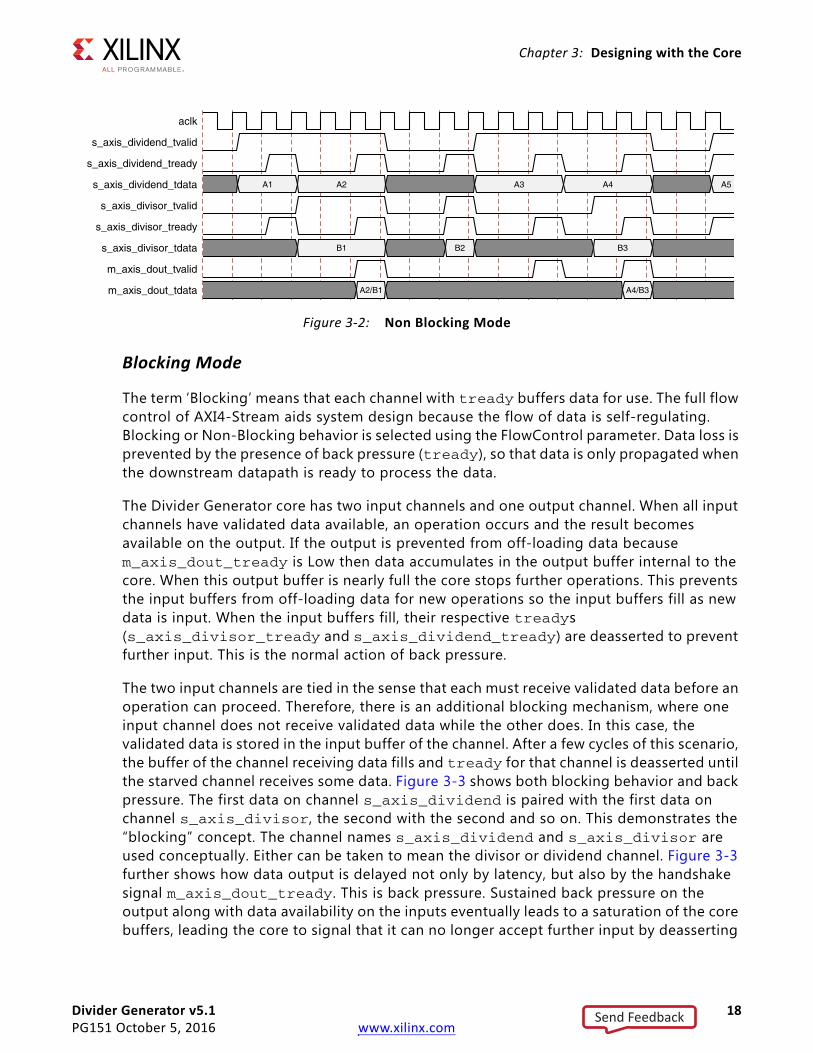
Non Blocking Mode
The Divider Generator core provides a mode intended to ease the migration from previous, non-AXI versions of this core. The term “Non-Blocking” is used to indicate that lack of data on one input channel does not cause incoming data on the other channel to be buffered. Also, back pressure from the output is not possible because in NonBlocking mode the output channel does not have a tready signal. The full flow control of AXI4-Stream is not always required. Blocking or Non-Blocking behavior is selected using the FlowControl parameter or user interface field. The choice of Blocking or NonBlocking applies to the whole core, not each channel individually. Channels still have the non-optional tvalid signal, which is analogous to the New Data (ND) signal on many cores prior to the adoption of AXI4-Stream. Without the facility to block dataflow, the internal implementation is much simplified, so fewer resources are required for this mode. This mode is recommended for users wishing to move to this version from a pre-AXI version with minimal change.
When all of the present input channels receive an active tvalid (and tready, if present, is asserted), an operation is validated and the output tvalid (suitably delayed by the latency of the core) is asserted to qualify the result. This is to allow a minimal migration from v3.0. If one channel receives tvalid and the other does not, then an operation does not occur, even if tready is present and asserted. Hence, unlike Blocking mode which is fully AXI4-Stream compliant, valid transactions on an individual channel can be ignored in NonBlocking mode.
For performance, ARESETn is registered internally, which delays its action by a clock cycle. The effect is that the cycle following the deassertion of ARESETn the core is still reset and does not accept input. tvalid is also inactive on the output channel for this cycle.
Figure 3-2 shows the NonBlocking mode in operation. For simplicity of illustration, the latency of the core is zero. As indicated by s_axis_dividend_tready and s_axis_divisor_tready, which are ultimately the same signal, the core can accept data on every third cycle. Data A1 in the dividend channel is ignored because s_axis_divisor_tvalid is deasserted. Data inputs A2 and B1 are accepted because both tvalids and tready are asserted.
X-Ref Target - Figure 3-1
Figure 3-1: Data Transfer in an AXI-Stream Channel
ACLK
TVALID
TREADY
TDATA
TLAST
TUSER
D1 D2 D3 D4
L1 L2 L3 L4
U1 U2 U3 U4
Send Feedback
Divider Generator v5.1 18PG151 October 5, 2016 www.xilinx.com
Chapter 3: Designing with the Core
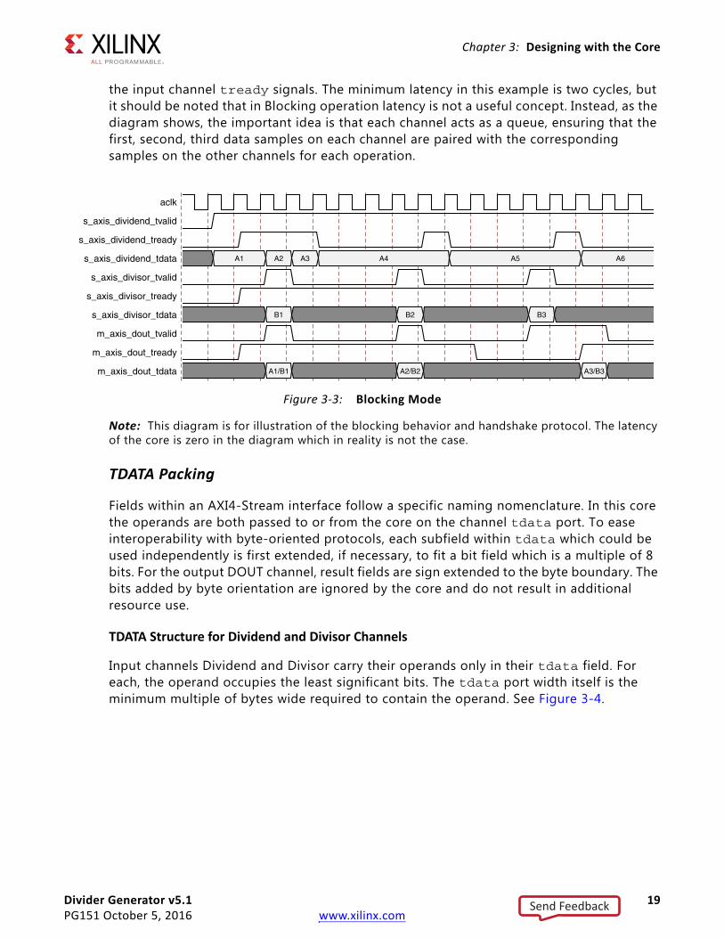
Blocking Mode
The term ‘Blocking’ means that each channel with tready buffers data for use. The full flow control of AXI4-Stream aids system design because the flow of data is self-regulating. Blocking or Non-Blocking behavior is selected using the FlowControl parameter. Data loss is prevented by the presence of back pressure (tready), so that data is only propagated when the downstream datapath is ready to process the data.
The Divider Generator core has two input channels and one output channel. When all input channels have validated data available, an operation occurs and the result becomes available on the output. If the output is prevented from off-loading data because m_axis_dout_tready is Low then data accumulates in the output buffer internal to the core. When this output buffer is nearly full the core stops further operations. This prevents the input buffers from off-loading data for new operations so the input buffers fill as new data is input. When the input buffers fill, their respective treadys (s_axis_divisor_tready and s_axis_dividend_tready) are deasserted to prevent further input. This is the normal action of back pressure.
The two input channels are tied in the sense that each must receive validated data before an operation can proceed. Therefore, there is an additional blocking mechanism, where one input channel does not receive validated data while the other does. In this case, the validated data is stored in the input buffer of the channel. After a few cycles of this scenario, the buffer of the channel receiving data fills and tready for that channel is deasserted until the starved channel receives some data. Figure 3-3 shows both blocking behavior and back pressure. The first data on channel s_axis_dividend is paired with the first data on channel s_axis_divisor, the second with the second and so on. This demonstrates the “blocking” concept. The channel names s_axis_dividend and s_axis_divisor are used conceptually. Either can be taken to mean the divisor or dividend channel. Figure 3-3 further shows how data output is delayed not only by latency, but also by the handshake signal m_axis_dout_tready. This is back pressure. Sustained back pressure on the output along with data availability on the inputs eventually leads to a saturation of the core buffers, leading the core to signal that it can no longer accept further input by deasserting
X-Ref Target - Figure 3-2
Figure 3-2: Non Blocking Mode
Send Feedback
Divider Generator v5.1 19PG151 October 5, 2016 www.xilinx.com
Chapter 3: Designing with the Core
the input channel tready signals. The minimum latency in this example is two cycles, but it should be noted that in Blocking operation latency is not a useful concept. Instead, as the diagram shows, the important idea is that each channel acts as a queue, ensuring that the first, second, third data samples on each channel are paired with the corresponding samples on the other channels for each operation.
.
Note: This diagram is for illustration of the blocking behavior and handshake protocol. The latency of the core is zero in the diagram which in reality is not the case.
TDATA Packing
Fields within an AXI4-Stream interface follow a specific naming nomenclature. In this core the operands are both passed to or from the core on the channel tdata port. To ease interoperability with byte-oriented protocols, each subfield within tdata which could be used independently is first extended, if necessary, to fit a bit field which is a multiple of 8 bits. For the output DOUT channel, result fields are sign extended to the byte boundary. The bits added by byte orientation are ignored by the core and do not result in additional resource use.
TDATA Structure for Dividend and Divisor Channels
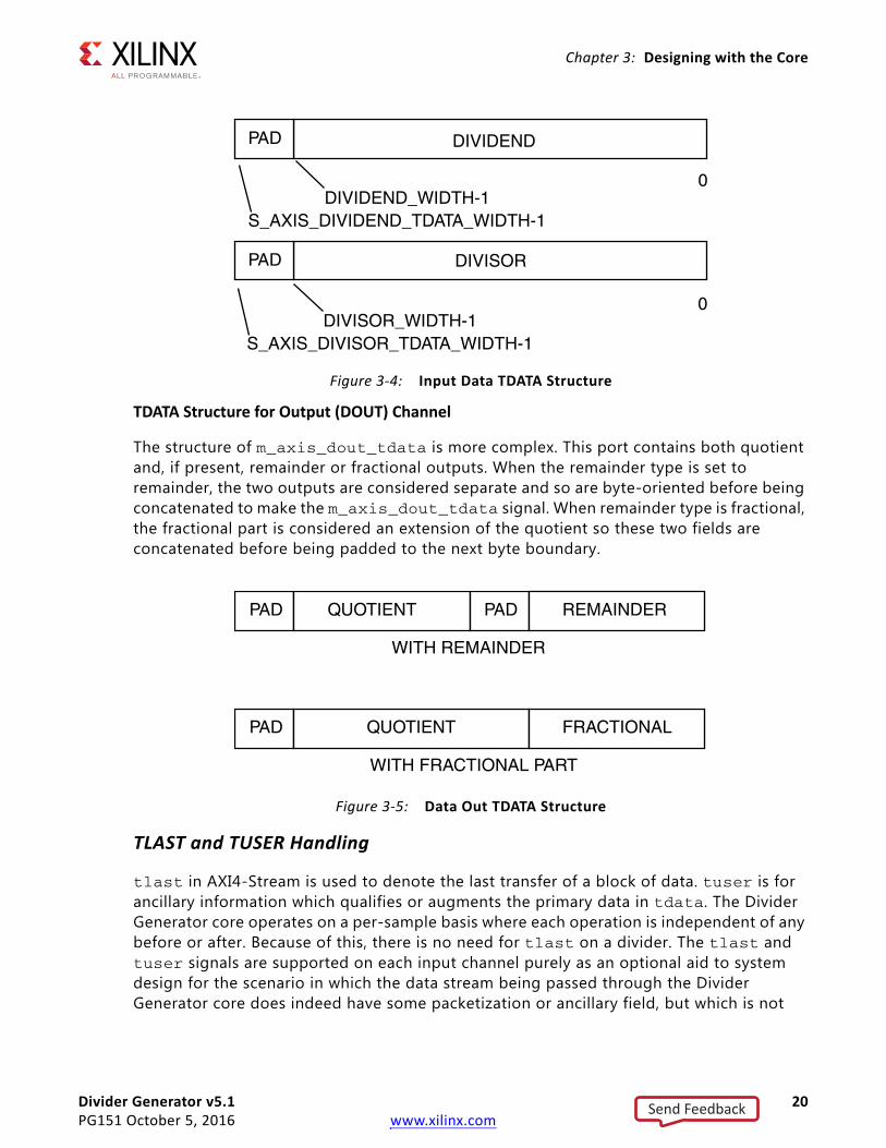
Input channels Dividend and Divisor carry their operands only in their tdata field. For each, the operand occupies the least significant bits. The tdata port width itself is the minimum multiple of bytes wide required to contain the operand. See Figure 3-4.
X-Ref Target - Figure 3-3
Figure 3-3: Blocking Mode
Send Feedback
Divider Generator v5.1 20PG151 October 5, 2016 www.xilinx.com
Chapter 3: Designing with the Core
TDATA Structure for Output (DOUT) Channel
The structure of m_axis_dout_tdata is more complex. This port contains both quotient and, if present, remainder or fractional outputs. When the remainder type is set to remainder, the two outputs are considered separate and so are byte-oriented before being concatenated to make the m_axis_dout_tdata signal. When remainder type is fractional, the fractional part is considered an extension of the quotient so these two fields are concatenated before being padded to the next byte boundary.
TLAST and TUSER Handling
tlast in AXI4-Stream is used to denote the last transfer of a block of data. tuser is for ancillary information which qualifies or augments the primary data in tdata. The Divider Generator core operates on a per-sample basis where each operation is independent of any before or after. Because of this, there is no need for tlast on a divider. The tlast and tuser signals are supported on each input channel purely as an optional aid to system design for the scenario in which the data stream being passed through the Divider Generator core does indeed have some packetization or ancillary field, but which is not
X-Ref Target - Figure 3-4
Figure 3-4: Input Data TDATA Structure
X-Ref Target - Figure 3-5
Figure 3-5: Data Out TDATA Structure
Send Feedback

Divider Generator v5.1 21PG151 October 5, 2016 www.xilinx.com
Chapter 3: Designing with the Core
relevant to the divider. The facility to pass tlast and/or tuser removes the burden of matching latency to the tdata path, which can be variable, through the divider.
When Divide_by_zero detect is selected, the signal indicating a division by zero is output on the least significant bit of the output channel tuser port.
TLAST Options
tlast for each input channel is optional. Each, when present, can be passed through the divider, or, when more than one channel has tlast enabled, can pass a logical AND or logical OR of the tlasts input. When no tlasts are present on any input channel, the output channel does not have tlast either.
TUSER Options
tuser for each input channel is optional. Each has user-selectable width. The Divider Generator core might also generate a tuser bit. This is when divide_by_zero detection is selected. These fields are concatenated, without any byte-orientation or padding, to form the output channel tuser field. The divide_by_zero bit occupies the least significant position, followed by the tuser field from the Divisor channel then tuser from the Dividend channel in the most significant position.
X-Ref Target - Figure 3-6
Figure 3-6: Data Out TUSER Structure
Send Feedback
Divider Generator v5.1 22PG151 October 5, 2016 www.xilinx.com
Chapter 4
Design Flow StepsThis chapter describes customizing and generating the core, constraining the core, and the simulation, synthesis and implementation steps that are specific to this IP core. More detailed information about the standard Vivado® design flows and the IP integrator can be found in the following Vivado Design Suite user guides:
• Vivado Design Suite User Guide: Designing IP Subsystems using IP Integrator (UG994) [Ref 3]
• Vivado Design Suite User Guide: Designing with IP (UG896) [Ref 4]
• Vivado Design Suite User Guide: Getting Started (UG910) [Ref 5]
• Vivado Design Suite User Guide: Logic Simulation (UG900) [Ref 6]
Customizing and Generating the CoreThis section includes information about using Xilinx® tools to customize and generate the core in the Vivado Design Suite.
If you are customizing and generating the core in the Vivado IP integrator, see the Vivado Design Suite User Guide: Designing IP Subsystems using IP Integrator (UG994) [Ref 3] for detailed information. IP integrator might auto-compute certain configuration values when validating or generating the design. To check whether the values do change, see the description of the parameter in this chapter. To view the parameter value, run the validate_bd_design command in the Tcl console.
You can customize the IP for use in your design by specifying values for the various parameters associated with the IP core using the following steps:
1. Select the IP from the IP catalog.
2. Double-click on the selected IP or select the Customize IP command from the toolbar or right-click menu.
For details, see the Vivado Design Suite User Guide: Designing with IP (UG896) [Ref 4] and the Vivado Design Suite User Guide: Getting Started (UG910) [Ref 5].
The Divider Generator core can be found in the Xilinx Blockset in the Math section. The block is called Divider Generator 5.1 The Divider Generator core interface in the Vivado
Send Feedback

Divider Generator v5.1 23PG151 October 5, 2016 www.xilinx.com
Chapter 4: Design Flow Steps
Integrated Design Environment (IDE) provides one page split into sections to set parameter values for the particular instantiation required. This section provides a description of each interface field. These fields are grouped as follows:
• Component Name: The base name of the output files generated for the core. Names must begin with a letter and be composed of any of the following characters: a to z, 0 to 9 and “_”.
Common Options
Describes parameters common to both implementations and allows the selection of the divider implementation.
• Algorithm Type: This selects between Radix-2, LUTMult and High Radix division solutions.
Dividend Channel
• Dividend Width: Specifies the number of integer bits provided on the DIVIDEND (s_axis_dividend_tdata) and QUOTIENT fields (subfield of m_axis_dout_tdata). This must be set to satisfy the largest possible quotient result. Due to the non-symmetry of twos complement representation bit growth from the dividend to quotient is possible, but only for the single combination of the most negative number divided by negative one (that is, -2(M-1)/-1). The width of dividend (and hence quotient) can be extended by 1 bit should this situation need to be accommodated
• Has TLAST: Specifies whether the this channel has a tlast port. The Divider Generator core does not use this information. The facility is provided to ease system design. tlast information is conveyed to the output channel with the same latency as the datapath.
• Has TUSER: Specifies whether this channel has a tuser port. As with tlast, the Divider Generator core does not use this information. tuser exists to ease system design. tuser bits are conveyed to the output with the same latency as the datapath.
• TUSER Width: Available when Has tuser is TRUE, this sets the width of the tuser port for this channel.
Divisor Channel
• Divisor Width: Specifies the number of integer bits provided on the DIVISOR field of s_axis_divisor_tdata. When the core is configured with remainder output, the width of the remainder is also equal to the value of this parameter.
• Has TLAST: Specifies whether the this channel has a tlast port. The Divider Generator core does not use this information. The facility is provided to ease system design. tlast information is conveyed to the output channel with the same latency as the datapath.
Send Feedback
Divider Generator v5.1 24PG151 October 5, 2016 www.xilinx.com
Chapter 4: Design Flow Steps
• Has TUSER: Specifies whether this channel has a tuser port. As with tlast, the Divider Generator core does not use this information. tuser exists to ease system design. tuser bits are conveyed to the output with the same latency as the datapath.
• TUSER Width: Available when Has tuser is TRUE, this sets the width of the tuser port for this channel.
Output Channel
• Remainder Type: This selects between remainder types Fractional and Remainder presented on the FRACTIONAL field of the output tdata port (m_axis_dout_tdata). Fractional remainder type is the only option for High Radix.
• Fractional Width: If Fractional remainder type is selected, this determines the number of bits provided on the FRACTIONAL field of the output channel (m_axis_dout_tdata). When High Radix is selected, the total output width (quotient part plus fractional part) is limited to 82.
The width of the quotient is equal to the width of the dividend and is set in the Dividend channel section.
The width of the tuser port is the sum of the present input channel tuser fields plus one if divide_by_zero detect is active. See AXI4-Stream Considerations in Chapter 3 for the internal structure of the tuser port.
This channel also has a tlast port if either of the input channels has a tlast port.
Radix-2 Options
• Clocks Per Division: Determines the throughput of the Radix-2 solution (interval in clocks between inputs (or outputs)). A low value for this parameter results in high throughput, but also in greater resource use.
High Radix and LUTMult Options
• Number of iterations (High Radix only): Read-only text field that reports the number of iterations performed by the High Radix engine for each divide. This sets the maximum throughput of the divider. To achieve this throughput, the operands must be supplied as soon as requested by the core s_axis_dividend_tready and s_axis_divisor_tready outputs.
• Throughput (High Radix only): Read-only text field that reports the maximum throughput that can be sustained by the divider when operands are supplied at a constant rate. In AXI blocking modes, throughput might be slightly higher due to buffering. This rate applies when FlowControl is set to NonBlocking and the output channel DOUT has no tready.
Send Feedback

Divider Generator v5.1 25PG151 October 5, 2016 www.xilinx.com
Chapter 4: Design Flow Steps
Common Options
Detect Divide-by-Zero: Check box. Determines if the core has a DIVIDE_BY_ZERO field in the output tuser port (m_axis_dout_tuser) to signal when a division by zero has been performed.
AXI4-Stream Options
• Flow Control: Blocking or NonBlocking. This is more fully explained in AXI4-Stream Considerations in Chapter 3. NonBlocking mode provides an easier migration path from the previous version of the Divider Generator core. Blocking mode eases data flow management to/from other AXI4-Stream blocking mode cores at the expense of some additional resource and latency.
• Optimize Goal: This applies only to blocking mode. When ACLKEN is selected and Optimize Goal is set to Resources, performance might be reduced. See Resource Utilization in Chapter 2.
• Output has TREADY: Selects whether the output channel has a tready signal. This is required to allow back pressure from downstream, for example, if connected to another AXI4-Stream Blocking core. Without tready, downstream circuitry cannot halt dataflow from the divider, but some resource is saved.
• Output TLAST Behavior: Selects the source of the output channel tlast signal. When neither or only one input channel has a tlast then the output tlast is not present or derives from the input tlast appropriately. When both input channels have tlast, the output channel tlast can derive from either alone, the logical OR of both inputs, or the logical AND of both inputs.
Latency Options
• Latency Configuration: Automatic (fully pipelined) or manual (determined by following field). Latency configuration for Radix2 solution is configurable only when clocks per division is set to 1. This is due to iterative feedback and hence non-optional registers when clocks per division is greater than 1.
• Latency: When Latency Configuration is set to Automatic, this field provides the latency from input to output in terms of clock enabled clock cycles. When Manual, this field is used to specify the latency required. When high performance (clock frequency) is not required, a lower value in this field can save resources.
Control Signals
• ACLKEN: Determines if the core has a clock enable input (ACLKEN).
• ARESETn: Determines if the core has an active-Low synchronous clear input (ARESETn).
Note:
Send Feedback

Divider Generator v5.1 26PG151 October 5, 2016 www.xilinx.com
Chapter 4: Design Flow Steps
a. The signal ARESETn always takes priority over ACLKEN, that is, ARESETn takes effect regardless of the state of ACLKEN.
b. The signal ARESETn is active-Low.
c. The signal ARESETn should be held active for at least two clock cycles. This is because, for performance, ARESETn is internally registered before being fed to the reset port of primitives.
User ParametersTable 4-1 shows the relationship between the fields in the Vivado IDE (described in Customizing and Generating the Core) and the User Parameters (which can be viewed in the Tcl console).
Table 4-1: Vivado IDE Parameter to User Parameter RelationshipVivado IDE Parameter/Value(1) User Parameter/Value(1) Default Value
Algorithm Type Algorithm_type Radix2
High Radix High_Radix
Radix2 Radix2
LutMult LutMult
Dividend Width dividend_and_quotient_width 16
Dividend Channel: Has TUSER dividend_has_tuser False
Dividend Channel: TUSER Width dividend_tuser_width 1
Dividend Channel: Has TLAST dividend_has_tlast False
Divisor Width divisor_width 16
Divisor Channel: Has TUSER divisor_has_tuser False
Divisor Channel: TUSER Width divisor_tuser_width 1
Divisor Channel: Has TLAST divisor_has_tlast False
Remainder Type remainder_type Remainder
Fractional Width fractional_width 16
Operand Sign operand_sign Signed
Clocks per Division clocks_per_division 1
Detect Divide-By-Zero divide_by_zero_detect False
Flow Control flowcontrol NonBlocking
Non Blocking NonBlocking
Blocking Blocking
Optimize Goal optimizegoal Resources
Output has TREADY outtready False
Output TLAST Behavior outtlastbehv Null
AND all TLASTs AND_all_TLASTs
Null Null
OR all TLASTs OR_all_TLASTs
Send Feedback

Divider Generator v5.1 27PG151 October 5, 2016 www.xilinx.com
Chapter 4: Design Flow Steps
Output GenerationFor details, see the Vivado Design Suite User Guide: Designing with IP (UG896) [Ref 4].
Constraining the CoreThis section contains information about constraining the core in the Vivado Design Suite.
Required ConstraintsThis section is not applicable for this IP core.
Device, Package, and Speed Grade SelectionsThis section is not applicable for this IP core.
Clock FrequenciesThis section is not applicable for this IP core.
Clock ManagementThis section is not applicable for this IP core.
Clock PlacementThis section is not applicable for this IP core.
Pass Dividend TLAST Pass_Dividend_TLAST
Pass Divisor TLAST Pass_Divisor_TLAST
Latency Configuration latency_configuration Automatic
Latency latency 18
ACLKEN aclken False
ARESETN aresetn False
Notes: 1. Parameter values are listed in the table where the GUI parameter value differs from the user parameter value. Such
values are shown in this table as indented below the associated parameter.
Table 4-1: Vivado IDE Parameter to User Parameter Relationship (Cont’d)
Vivado IDE Parameter/Value(1) User Parameter/Value(1) Default Value
Send Feedback
Divider Generator v5.1 28PG151 October 5, 2016 www.xilinx.com
Chapter 4: Design Flow Steps
BankingThis section is not applicable for this IP core.
Transceiver PlacementThis section is not applicable for this IP core.
I/O Standard and PlacementThis section is not applicable for this IP core.
SimulationFor comprehensive information about Vivado® simulation components, as well as information about using supported third party tools, see the Vivado Design Suite User Guide: Logic Simulation (UG900) [Ref 6].
IMPORTANT: For cores targeting 7 series or Zynq-7000 devices, UNIFAST libraries are not supported. Xilinx IP is tested and qualified with UNISIM libraries only.
Synthesis and ImplementationFor details about synthesis and implementation, see the Vivado® Design Suite User Guide: Designing with IP [Ref 4].
Send Feedback

Divider Generator v5.1 29PG151 October 5, 2016 www.xilinx.com
Chapter 5
C ModelThis chapter details the C Model provided with the core.
The Divider Generator bit accurate C model is a self-contained, linkable, shared library that models the functionality of this core with finite precision arithmetic. This model provides a bit accurate representation of the various modes of the Divider Generator core and is suitable for inclusion in a larger framework for system-level simulation or core-specific verification.
The C model is an optional output of the Vivado®Design Suite.
Features• Bit accurate with the Divider Generator core.
• Available for 32-bit and 64-bit Linux platforms.
• Available for 32-bit and 64-bit Windows platforms.
• Supports all features of the Divider Generator core with the exception of those affecting timing or AXI4-Stream configuration (tuser is also not included).
• Designed for integration into a larger system model.
• Example C code showing how to use the C model functions.
OverviewThe model consists of a set of C functions that reside in a shared library. Example C code is provided to demonstrate how these functions form the interface to the C model. Full details of this interface are given in C Model Interface.
The model is bit accurate but not cycle-accurate; it performs exactly the same operations as the core. However, it does not model the core latency, interface signals or tuser feature.
Send Feedback

Divider Generator v5.1 30PG151 October 5, 2016 www.xilinx.com
Chapter 5: C Model
Unpacking and Model ContentsThere are separate ZIP files containing all the files necessary for use. Each ZIP file contains:
• C model shared library
• C model header file
• Example code showing how to call the C model
Table 5-1 and Table 5-2 list the contents of each ZIP file.
Table 5-1: C Model ZIP File Contents: Linux
File Description
div_gen_v5_1_bitacc_cmodel.h Header file which defined the C model API
libIp_div_gen_v5_1_bitacc_cmodel.so Model shared object library
run_bitacc_cmodel.c Example program for calling the C model.
gmp.h MPIR header file, used by the C model
libgmp.so.11 MPIR library, used by the C model
div_gen_v5_1_bitacc_mex.cpp MATLAB MEX function source
make_div_gen_v5_1_mex.m MATLAB MEX function compilation script
run_div_gen_v5_1_mex.m MATLAB MEX function example script
@div_gen_v5_1_bitacc MATLAB MEX function class directory
Table 5-2: C Model ZIP File Contents: Windows
File Description
div_gen_v5_1_bitacc_cmodel.h Header file which defined the C model API
libIp_div_gen_v5_1_bitacc_cmodel.dll Model dynamically linked library
libIp_div_gen_v5_1_bitacc_cmodel.lib Model LIB file for compiling
run_bitacc_cmodel.c Example program for calling the C model
gmp.h MPIR header file, used by the C model
libgmp.dll MPIR library, used by the C model
libgmp.lib MPIR .lib file for compiling
div_gen_v5_1_bitacc_mex.cpp MATLAB MEX function source
make_div_gen_v5_1_mex.m MATLAB MEX function compilation script
run_div_gen_v5_1_mex.m MATLAB MEX function example script
@div_gen_v5_1_bitacc MATLAB MEX function class directory
Send Feedback
Divider Generator v5.1 31PG151 October 5, 2016 www.xilinx.com
Chapter 5: C Model
Installation
Linux• Unpack the contents of the ZIP file.
• Ensure that the directory where the libIp_div_gen_v5_1_bitacc_cmodel.so resides is included in the path of the environment variable LD_LIBRARY_PATH.
Windows• Unpack the contents of the ZIP file.
• Ensure that the directory where the libIp_div_gen_v5_1_bitacc_cmodel.dll resides is:
° Included in the path of the environment variable PATH, or
° In the directory in which the executable that calls the C model is run.
C Model InterfaceAn example file, run_bitacc_cmodel.c is included. This demonstrates how to call the C model. See this file for examples of using the interface described in this section.
The Application Programming Interface (API) of the C model is defined in the header file div_gen_v5_1_bitacc_cmodel.h. This interface consists of data structures and functions as described in the following sections.
Note that the division by zero output of the C model is always enabled so a data structure must be allocated for this return value set. When division by zero is detected, the outputs of quotient and remainder for that sample are undefined and might differ from the core hdl output. Only in this case is the C model not bit accurate with the HDL.
Data TypesThe C types defined for the Divider Generator C model are listed in Table 5-3.
Table 5-3: Data Types
Name Type Description
xip_uint Unsignedinteger Base type for divide by zero output
xip_array_uint Struct Structure to hold array of divide_by_output values
xip_array_mpz Struct Structure to hold array of operand values (both input and output)
Send Feedback

Divider Generator v5.1 32PG151 October 5, 2016 www.xilinx.com
Chapter 5: C Model
The xip_array_uint and xip_array_mpz types are structures with the following members:
• Data: a pointer to the array of data values
• Data_size: of type size_t, which describes the total size of the data array.
• Data_capacity: also of type size_t, which described how much of the array is currently populated.
• Dim: a pointer to a size_t array of values which indicate the size of each dimension.
• Dim_size. Also of type size_t. This indicates the number of dimensions of the data array.
• Dim_capacity: indicates how much of the dimension array is currently populated.
• Owner: This unsigned in member is provided as a handle for when the data structure is intended to be passed from one core to another, but is not used by any of the Divider Generator C model functions.
Data ValuesThe Divider Generator core input and output fields are in standard unsigned or signed (twos complement) binary form with widths from 2 bits to 64 bits wide per operand or result field.
The Divider Generator C model expects data to be in the C type mpz_t, equal to the raw value of the twos complement bit vector input to the HDL. The output form is also of mpz_t, again corresponding to the bit vector of the output. For signed Radix-2 with fractional output, the sign is included as the leading bit of the fractional value just as it is for the core.
FunctionsThere are several C model functions accessible to the user.
xip_div_gen_v5_1_status Int Error code return from many C model functions. 0 indicates success. Any other value indicates failure
xip_status Int Same as xip_div_gen_v5_1_status, but used for functions which are not core-specific
xip_div_gen_v5_1_config Struct
The configuration of the core itself. The members of this structure are listed in the div_gen_v5_1_bitacc_cmodel.h file. The names closely match the same names in XCI files. The div_gen_v5_1_bitacc_cmodel.h file also contains #defined values for all.
xip_div_gen_v5_1 Struct Type defined which C (not C++) can use as a handle (pointer) to a C++ object - the C model itself.
Table 5-3: Data Types (Cont’d)
Name Type Description
Send Feedback

Divider Generator v5.1 33PG151 October 5, 2016 www.xilinx.com
Chapter 5: C Model
Information Functions
Table 5-4 lists the information functions. The prototypes for these functions can be found in the C model header file.
Initialization Functions
The functions to create, configure and destroy the C model and associated data structures are listed in Table 5-5.
Table 5-4: Information Functions
Name Return Arguments Description
xip_div_gen_get_version Const char* NoneReturn the Divider Generator version as a null terminated string. For v5.1 this is ‘5.1’.
xip_div_gen_v5_1_get_default_config xip_div_gen_v5_1_status xip_div_gen_
v5_1_config*
Populates the contents of structure point to by the input argument with the value of a default configuration
Table 5-5: Initialization Functions
Name Return Arguments Description
xip_div_gen_v5_1_createPointer to structureholding configurationof C model object
Pointer to structureholding configuration
Creates C model object and returns pointer to config structure (which is pointer to C model itself).
xip_div_gen_v5_1_destroy xip_div_gen_v5_1_statusPointer toxip_div_gen_v5_1(C model itself)
Deallocates memory owned by C model and destroys C model itself.
xip_div_gen_v5_1_get_config xip_div_gen_v5_1_status
Pointer to C model,pointer to configuration structure
Copied the contents of the configuration of the C model indicates to the designated configuration structure.
xip_array_#TYPE#_create Pointer to the createddata structure None
Allocates memory for the structure itself, not the array members within it.
xip_array_#TYPE#_reserve_data xip_status
Pointer to data structure, maximum number of elements in data array.
(Re)allocates enough memory for the maximum size. Error is returned if the data_capacity of the structure is greater than the space allocated
Send Feedback

Divider Generator v5.1 34PG151 October 5, 2016 www.xilinx.com
Chapter 5: C Model
Execution Functions
The run time functions of the C model are described in Table 5-6.
CompilingCompilation of user code requires access to the div_gen_v5_1_bitacc_cmodel.h header file and the header files of the MPIR dependent libraries, gmp.h. The header files should be copied to a location where they are available to the compiler. Depending on the location chosen, the include search path of the compiler might need to be modified.
The div_gen_v5_1_bitacc_cmodel.h header file must be included first, because it defines some symbols that are used in the MPIR header files. The div_gen_v5_1_bitacc_cmodel.h header file includes the MPIR header files, so these do not need to be explicitly included in source code that uses the C model. When compiling on Windows, the symbol NT must be defined, either by a compiler option, or in user source code before the div_gen_v5_1_bitacc_cmodel.h header file is included.
xip_array_#TYPE#_reserve_dim xip_status
Pointer to data structure, maximum number of dimensions.
Allocates a small array which is to contain the size of each dimension of the data array. For example, 100 samples x 4 channels x 3 fields.
xip_array_#TYPE#_destroy xip_status
Pointer to data structure.
Frees up the memory allocated for the data array, the dimension array, and the data structure itself.
xip_array_#TYPE#_alloc xip_status
Number of samples (int)
Creates and allocates data structures suitable for divider operands.
Table 5-6: Execution Functions
Name Return Arguments Description
xip_div_gen_v5_1_data_do xip_div_gen_v5_1_status
Pointers to C model, Pointers to data structures for divisor, dividend, quotient (inc fractional part), remainder, divide_by_zero, Number of samples (int).
Executes division on input data structures and populates output data structures.
Table 5-5: Initialization Functions
Name Return Arguments Description
Send Feedback
Divider Generator v5.1 35PG151 October 5, 2016 www.xilinx.com
Chapter 5: C Model
LinkingTo use the C model the user executable must be linked against the correct libraries for the target platform.
Note: The C model uses MPIR libraries. It is also possible to use GMP or MPIR libraries from other sources, for example, compiled from source code. For details, see Dependent Libraries.
Linux The executable must be linked against the following shared object libraries:
• libgmp.so.11
• libIp_div_gen_v5_1_bitacc_cmodel.so
Using GCC, linking is typically achieved by adding the following command line options:
-L. -Wl,-rpath,. -lIp_div_gen_v5_1_bitacc_cmodel
This assumes the shared object libraries are in the current directory. If this is not the case, the -L. option should be changed to specify the library search path to use.
Using GCC, the provided example program run_bitacc_cmodel.c can be compiled and linked using the following command:
gcc -x c++ -I. -L. -lIp_div_gen_v5_1_bitacc_cmodel -Wl,-rpath,. -o run_bitacc_cmodel run_bitacc_cmodel.c
WindowsThe executable must be linked against the following dynamic link libraries:
• libgmp.dll
• libIp_div_gen_v5_1_bitacc_cmodel.dll
Depending on the compiler, the import libraries might also be required:
• libgmp.lib
• libIp_div_gen_v5_1_bitacc_cmodel.lib
Using Microsoft Visual Studio, linking is typically achieved by adding the import libraries to the Additional Dependencies entry under the Linker section of Project Properties.
Send Feedback
Divider Generator v5.1 36PG151 October 5, 2016 www.xilinx.com
Chapter 5: C Model
Dependent LibrariesThe C model uses the MPIR library. This is governed by the GNU Lesser General Public License. You can obtain source code for the MPIR library from www.xilinx.com/guest_resources/gnu/. A pre-compiled MPIR library is provided with the C model, using the following version:
MPIR 2.6.0
As MPIR is a compatible alternative to GMP, the GMP library can be used in place of MPIR. It is possible to use GMP or MPIR libraries from other sources, for example, compiled from source code.
GMP and MPIR in particular contain many low level optimizations for specific processors. The libraries provided are compiled for a generic processor on each platform, using no optimized processor-specific code. These libraries work on any processor, but run more slowly than libraries compiled to use optimized processor-specific code. For the fastest performance, compile libraries from source on the machine on which you run the executables.
Source code and compilation scripts are provided for the version of MPIR that was used to compile the provided libraries. Source code and compilation scripts for any version of the libraries can be obtained from the GMP [Ref 7] and MPIR [Ref 8] websites.
Note: If compiling MPIR using its configure script (for example, on Linux platforms), use the --enable-gmpcompat option when running the configure script. This generates a libgmp.so library and a gmp.h header file that provide full compatibility with the GMP library.
ExampleSee the file provided called run_bitacc_cmodel for example C code which creates, sets up, executes and destroys the C model.
MATLAB InterfaceA MEX function and MATLAB® software class is provided to simplify the integration with MATLAB. The MEX function provides a low-level wrapper around the underlying C model, while the class file provides a convenient interface to the MEX function.
Send Feedback
Divider Generator v5.1 37PG151 October 5, 2016 www.xilinx.com
Chapter 5: C Model
CompilingSource code for a MATLAB MEX function is provided. This can be compiled within MATLAB by changing to the directory which contains the code and running the make_div_gen_v5_1_bitacc_mex.m script.
InstallationTo use the MEX function the compiled MEX function must be present on the MATLAB search path. This can be achieved by either of the following:
1. Add the directory where the compiled MEX function is located to the MATLAB search path (see the MATLAB addpath function) OR
2. Copy the files to a location already on the MATLAB search path.
As with all uses of the C model, the correct C model libraries also need to be present on the platform library search path (that is, PATH or LD_LIBRARY_PATH).
MATLAB Class InterfaceThe @div_gen_v5_1_bitacc class handles the create/destroy semantics on the C model. The class provides objects for each of the data and control structures defined for the C model and previously described in Data Types. MATLAB arrays are used the mapping of types as in Table 5-7.
The class provides these methods:
Constructor
[model]=div_gen_v5_1_bitacc[model]=div_gen_v5_1_bitacc(config)[model]=div_gen_v5_1_bitacc(field, value [, field,value]*)
* indicates an optional parameter
The first version of the function call constructs a model object using the default configuration. The second version constructs a model object from a structure that specified the configuration parameter values to use. The third version is the same as the second, but allows the configuration to be specified as a series of (parameter name, value) pairs rather than a single structure. The names and valid values of configuration parameters are identical to those previously described for the C model in Data Types.
Table 5-7: C Model Type Mapping
C Model type MATLAB Type
xip_real double
Send Feedback
Divider Generator v5.1 38PG151 October 5, 2016 www.xilinx.com
Chapter 5: C Model
The MATLAB configuration structure can contain an additional element, PersistentMemory. When the element is set to TRUE the internal data memory state of the model is retained following a call to the run function. Otherwise, the model is reset after the data is returned. PersistentMemory is set to false by default.
Get Version
[version] = get_version(model)
This method returns the version strinf of the c model library used.
Get Configuration
[config] = get_configuration(model)
This method returns the current parameters structure of a model object. If the model object is empty the method returns the default configuration. If the model object has been created, the method returns the configuration parameters that were used to create it.
Divide
[quotient]=divide(model, dividend, divisor)[quotient remainder]=divide(model, dividend, divisor)
Each of these methods causes the model to execute. The first form applies if the model has been configured with fractional remainder type. The second form applies if the model has been configured with remainder output.
ExampleThe run_div_gen_v5_1_bitacc_mex.m file contains a MATLAB script with several examples of differently configured models showing how to configure and run each.
To run the sample script:
1. Compile the MEX function with the make_div_gen_v5_1_bitacc_mex.m script (see Compiling).
2. Install the MEX function (see Installation).
3. Execute the run_div_gen_v5_1_bitacc_mex.m script.
Send Feedback
Divider Generator v5.1 39PG151 October 5, 2016 www.xilinx.com
Chapter 6
Test BenchThis chapter contains information about the test bench provided in the Vivado® Design Suite.
When the core is generated using the Vivado Design Suite, a demonstration test bench is created. This is a simple VHDL test bench that exercises the core.
The demonstration test bench source code is one VHDL file: demo_tb/tb_<component_name>.vhd in the Vivado output directory. The source code is comprehensively commented.
Using the Demonstration Test BenchThe demonstration test bench instantiates the generated Divider Generator core.
Compile the netlist and the demonstration test bench into the work library (see your simulator documentation for more information on how to do this). Then simulate the demonstration test bench. View the test bench signals in your simulator waveform viewer to see the operations of the test bench.
Demonstration Test Bench in DetailThe demonstration test bench performs the following tasks:
• Instantiates the core
• Generates input data
• Generates a clock signal
• Drives the input signals of the core to demonstrate core features
• Checks that the output signals of he core obey AXI4-Stream protocol rules (data values are not checked to keep the test bench simple)
• Provides signals showing the separate fields of AXI4-Stream tdata and tuser signals
The demonstration test bench drives the core input signals to demonstrate the features and modes of operation of the core. The operations performed by the demonstration test bench
Send Feedback

Divider Generator v5.1 40PG151 October 5, 2016 www.xilinx.com
Chapter 6: Test Bench
are appropriate for the configuration of the generated core, and are a subset of the following operations:
1. An initial phase where the core is initialized and no operations are performed.
2. Perform a single operation, and wait for the result.
3. Perform 100 consecutive operations with incrementing data.
4. Perform operations while demonstrating the use and effects of the AXI4-Stream control signals.
5. If ACLKEN is present: Demonstrate the effect of toggling ACLKEN.
6. If ARESETn is present: Demonstrate the effect of asserting ARESETn.
The clock frequency of the core can be modified by changing the CLOCK_PERIOD constant.
Send Feedback
Divider Generator v5.1 41PG151 October 5, 2016 www.xilinx.com
Appendix A
Migrating and UpgradingThis appendix contains information about migrating a design from the ISE® Design Suite to the Vivado® Design Suite, and for upgrading to a more recent version of the IP core. For customers upgrading in the Vivado Design Suite, important details (where applicable) about any port changes and other impact to user logic are included.
Migrating to the Vivado Design SuiteFor information on migrating from Xilinx® ISE Design Suite tools to the Vivado Design Suite, see the ISE to Vivado Design Suite Migration Guide (UG911) [Ref 9].
Upgrading in the Vivado Design SuiteThis section provides information about any changes to the user logic or port designations that take place when you upgrade to a more current version of this IP core in the Vivado Design Suite.
Migrating from v4.0 or v5.0 to v5.1
Port Changes
There are no changes to ports, parameters or behavior from v4.0 to v5.1, nor from v5.0 to v5.1.
Latency Changes
There is no change to latency between v4.0 or v5.0 and v5.1.
Functionality Changes
There are no functional changes between v4.0 or v5.0 and v5.1.
Send Feedback

Divider Generator v5.1 42PG151 October 5, 2016 www.xilinx.com
Appendix A: Migrating and Upgrading
Migrating from v3.0 to v5.1
Port Changes
Table A-1 details the changes to port naming, additional or deprecated ports and polarity changes.
Table A-1: Port Changes from Version 3.0 to Version 5.1
Version 3.0 Version 5.0 Notes
CLK aclk Rename only
CE ACLKEN Rename only
SCLR ARESETnRename and change of sense (now active-Low). Note the recommendation that ARESETn should be asserted for a minimum of 2 cycles.
DIVIDEND s_axis_dividend_tdata (N-1:0)
DIVISOR s_axis_divisor_tdata (M-1:0)
QUOTIENTm_axis_dout_tdata(S-1:0)
Both Quotient and Fractional (or remainder) map to m_axis_dout_tdata. See TDATA Structure for Output (DOUT) Channel in Chapter 3 for details.FRACTIONAL
NDDeprecated. However this is analogous to the tvalid signals. See Instructions for Minimum Change Migration (v3.0 to v5.1).
RDYDeprecated. However, this is analogous to tvalid on the output channel. See Instructions for Minimum Change Migration (v3.0 to v5.1).
RFDDeprecated. However, this is analogous to TREADY on the input channels. See Instructions for Minimum Change Migration (v3.0 to v5.1)
DIVIDE_BY_ZERO m_axis_dout_tuser(0)When this signal is selected to appear, it occupies the LSB of the output tuser port. See TUSER Options in Chapter 3 for details.
s_axis_dividend_tvalidtvalid (AXI4-Stream channel handshake signal) for each channels_axis_divisor_tvalid
m_axis_dout_tvalid
s_axis_dividend_treadytready (AXI4-Stream channel handshake signal) for each channel.s_axis_divisor_tready
m_axis_dout_tready
s_axis_dividend_tlast tlast (AXI4-Stream packet signal indicating the last transfer of a data structure) for each channel. The Divider Generator core does not use tlast, but provides the facility to pass tlast with the same latency as tdata.
s_axis_divisor_tlast
m_axis_dout_tlast
Send Feedback

Divider Generator v5.1 43PG151 October 5, 2016 www.xilinx.com
Appendix A: Migrating and Upgrading
Latency Changes
With the addition of AXI4-Stream interfaces, the latency of the Divider Generator core v5.1 is different compared to v3.0 for AXI Blocking mode. Latency is the same as v3.0 in v5.1 for AXI Non-Blocking mode.
Importantly, when in Blocking Mode, the latency of the core is variable due to the FIFO nature of the AXI4-Stream protocol, so only the minimum possible latency can be determined. Relative to v3.0, with Blocking and output tready present, minimum latency is 3 cycles greater. With no output tready, minimum latency is increased by one cycle only.
Instructions for Minimum Change Migration (v3.0 to v5.1)To configure the Divider Generator core v5.1 to most closely mimic the behavior of v3.0 the translation is as follows:
Parameters
• Set FlowControl to NonBlocking.
All other new parameters default to FALSE and can be ignored.
Ports
• Rename and map signals as detailed in Port Changes.
• Map ND to both s_axis_dividend_tvalid and s_axis_divisor_tvalid.
• Map RFD to s_axis_dividend_tready (s_axis_divisor_tready can be used equally).
• Map RDY to m_axis_dout_tvalid.
Performance and resource use is mostly unchanged compared with Divider Generator v3.0 other than small changes due to the use of a different version of the implementation tools.
s_axis_dividend_tuser tuser (AXI4-Stream ancillary field for application-specific information) for each channel. The Divider Generator core does not use tuser, but provides the facility to pass tuser with the same latency as tdata.
s_axis_divisor_tuser
m_axis_dout_tuser
Table A-1: Port Changes from Version 3.0 to Version 5.1 (Cont’d)
Version 3.0 Version 5.0 Notes
Send Feedback
Divider Generator v5.1 44PG151 October 5, 2016 www.xilinx.com
Appendix A: Migrating and Upgrading
Functionality ChangesFrom v3.0 to v5.1, there are functional changes due to the adoption of AXI4-Stream Interfaces. See Instructions for Minimum Change Migration (v3.0 to v5.1) and AXI4-Stream Considerations in Chapter 3.
Simulation ChangesStarting with Divider Generator v5.1 behavioral simulation models have been replaced with IEEE Encrypted VHDL. The resulting model is bit and cycle accurate with the final netlist. For more information on simulation see the Vivado Design Suite User Guide: Logic Simulation (UG900) [Ref 6].
Send Feedback

Divider Generator v5.1 45PG151 October 5, 2016 www.xilinx.com
Appendix B
DebuggingThis appendix includes details about resources available on the Xilinx Support website and debugging tools.
Finding Help on Xilinx.comTo help in the design and debug process when using the Divider Generator, the Xilinx Support web page contains key resources such as product documentation, release notes, answer records, information about known issues, and links for opening further product support.
DocumentationThis product guide is the main document associated with the Divider Generator. This guide, along with documentation related to all products that aid in the design process, can be found on the Xilinx Support web page or by using the Xilinx® Documentation Navigator.
Download the Xilinx Documentation Navigator from the Downloads page. For more information about this tool and the features available, open the online help after installation.
Answer RecordsAnswer Records include information about commonly encountered problems, helpful information on how to resolve these problems, and any known issues with a Xilinx product. Answer Records are created and maintained daily ensuring that users have access to the most accurate information available.
Answer Records for this core can be located by using the Search Support box on the main Xilinx support web page. To maximize your search results, use keywords such as
• Product name
• Tool message(s)
• Summary of the issue encountered
A filter search is available after results are returned to further target the results.
Send Feedback

Divider Generator v5.1 46PG151 October 5, 2016 www.xilinx.com
Appendix B: Debugging
Master Answer Record for the Divider Generator
AR: 54499
Technical SupportXilinx provides technical support at the Xilinx Support web page for this LogiCORE™ IP product when used as described in the product documentation. Xilinx cannot guarantee timing, functionality, or support if you do any of the following:
• Implement the solution in devices that are not defined in the documentation.
• Customize the solution beyond that allowed in the product documentation.
• Change any section of the design labeled DO NOT MODIFY.
To contact Xilinx Technical Support, navigate to the Xilinx Support web page.
Debug ToolsThere are many tools available to address Divider Generator design issues. It is important to know which tools are useful for debugging various situations.
Vivado Design Suite Debug FeatureThe Vivado® Design Suite debug feature inserts logic analyzer and virtual I/O cores directly into your design. The debug feature also allows you to set trigger conditions to capture application and integrated block port signals in hardware. Captured signals can then be analyzed. This feature in the Vivado IDE is used for logic debugging and validation of a design running in Xilinx devices.
The Vivado logic analyzer is used with the logic debug IP cores, including:
• ILA 2.0 (and later versions)
• VIO 2.0 (and later versions)
See the Vivado Design Suite User Guide: Programming and Debugging (UG908) [Ref 10].
C Model ReferenceSee Chapter 5, C Model in this guide for tips and instructions for using the provided C Model files to debug your design.
Send Feedback

Divider Generator v5.1 47PG151 October 5, 2016 www.xilinx.com
Appendix B: Debugging
Simulation DebugThe simulation debug flow for Mentor Graphics Questa Simulator (QuestaSim) is illustrated in Figure B-1. A similar approach can be used with other simulators.
X-Ref Target - Figure B-1
Figure B-1: QuestaSim Debug Flow Diagram
Send Feedback

Divider Generator v5.1 48PG151 October 5, 2016 www.xilinx.com
Appendix B: Debugging
AXI4-Stream Interface DebugIf data is not being transmitted or received, check the following conditions:
• If transmit <interface_name>_tready is stuck Low following the <interface_name>_tvalid input being asserted, the core cannot send data.
• If the receive <interface_name>_tvalid is stuck Low, the core is not receiving data.
• Check that the aclk inputs are connected and toggling.
• Check that the AXI4-Stream waveforms are being followed as described in AXI4-Stream Considerations in Chapter 3.
• Check core configuration.
Send Feedback
Divider Generator v5.1 49PG151 October 5, 2016 www.xilinx.com
Appendix C
Additional Resources and Legal Notices and Legal Notices
Xilinx ResourcesFor support resources such as Answers, Documentation, Downloads, and Forums, see Xilinx Support.
ReferencesThese documents provide supplemental material useful with this product guide:
1. Xilinx Vivado Design Suite AXI Reference Guide (UG1037)
2. AMBA® AXI4-Stream Protocol Specification (ARM IHI 0051A)
3. Vivado® Design Suite User Guide: Designing IP Subsystems using IP Integrator (UG994)
4. Vivado Design Suite User Guide: Designing with IP (UG896)
5. Vivado Design Suite User Guide: Getting Started (UG910)
6. Vivado Design Suite User Guide: Logic Simulation (UG900)
7. The GNU Multiple Precision Arithmetic (GMP) Library gmplib.org
8. The GNU Multiple Precision Integers and Rationals (MPIR) library (www.mpir.org)
9. ISE® to Vivado Design Suite Migration Guide (UG911).
10. Vivado Design Suite User Guide: Programming and Debugging (UG908)
11. Computer Arithmetic Algorithms and Hardware Designs, Behrooz Parhami. Oxford Press, 2000.
12. Proceedings 12th Symposium on Computer Arithmetic, IEEE Computer Society Press, 1995.
13. Synthesis and Simulation Design Guide (UG626)
Send Feedback

Divider Generator v5.1 50PG151 October 5, 2016 www.xilinx.com
Appendix C: Additional Resources and Legal Notices and Legal Notices
Revision HistoryThe following table shows the revision history for this document.
Please Read: Important Legal NoticesThe information disclosed to you hereunder (the “Materials”) is provided solely for the selection and use of Xilinx products. To the maximum extent permitted by applicable law: (1) Materials are made available “AS IS” and with all faults, Xilinx hereby DISCLAIMS ALL WARRANTIES AND CONDITIONS, EXPRESS, IMPLIED, OR STATUTORY, INCLUDING BUT NOT LIMITED TO WARRANTIES OF MERCHANTABILITY, NON-INFRINGEMENT, OR FITNESS FOR ANY PARTICULAR PURPOSE; and (2) Xilinx shall not be liable (whether in contract or tort, including negligence, or under any other theory of liability) for any loss or damage of any kind or nature related to, arising under, or in connection with, the Materials (including your use of the Materials), including for any direct, indirect, special, incidental, or consequential loss or damage (including loss of data, profits, goodwill, or any type of loss or damage suffered as a result of any action brought by a third party) even if such damage or loss was reasonably foreseeable or Xilinx had been advised of the possibility of the same. Xilinx assumes no obligation to correct any errors contained in the Materials or to notify you of updates to the Materials or to product specifications. You may not reproduce, modify, distribute, or publicly display the Materials without prior written consent. Certain products are subject to the terms and conditions of Xilinx's limited warranty, please refer to Xilinx's Terms of Sale which can be viewed at http://www.xilinx.com/legal.htm#tos; IP cores may be subject to warranty and support terms contained in a license issued to you by Xilinx. Xilinx products are not designed or intended to be fail-safe or for use in any application requiring fail-safe performance; you assume sole risk and liability for use of Xilinx products in such critical applications, please refer to Xilinx's Terms of Sale which can be viewed at http://www.xilinx.com/legal.htm#tos.AUTOMOTIVE APPLICATIONS DISCLAIMERAUTOMOTIVE PRODUCTS (IDENTIFIED AS “XA” IN THE PART NUMBER) ARE NOT WARRANTED FOR USE IN THE DEPLOYMENT OF AIRBAGS OR FOR USE IN APPLICATIONS THAT AFFECT CONTROL OF A VEHICLE (“SAFETY APPLICATION”) UNLESS THERE IS A SAFETY CONCEPT OR REDUNDANCY FEATURE CONSISTENT WITH THE ISO 26262 AUTOMOTIVE SAFETY STANDARD (“SAFETY DESIGN”). CUSTOMER SHALL, PRIOR TO USING OR DISTRIBUTING ANY SYSTEMS THAT INCORPORATE PRODUCTS, THOROUGHLY TEST SUCH SYSTEMS FOR SAFETY PURPOSES. USE OF PRODUCTS IN A SAFETY APPLICATION WITHOUT A SAFETY DESIGN IS FULLY AT THE RISK OF CUSTOMER, SUBJECT ONLY TO APPLICABLE LAWS AND REGULATIONS GOVERNING LIMITATIONS ON PRODUCT LIABILITY.© Copyright 2013–2016 Xilinx, Inc. Xilinx, the Xilinx logo, Artix, ISE, Kintex, Spartan, Virtex, Vivado, Zynq, and other designated brands included herein are trademarks of Xilinx in the United States and other countries. AMBA, AMBA Designer, ARM, ARM1176JZ-S, CoreSight, Cortex, PrimeCell, and MPCore are trademarks of ARM in the EU and other countries. All other trademarks are the property of their respective owners.
Date Version Revision10/05/2016 5.1 Latency description updated.
11/18/2015 5.1 UltraScale device support added.
06/24/2015 5.1 • Added MATLAB Interface to C Model chapter
• Radix-2 latency description updated
04/02/2014 5.1 • Added link to resource utilization spreadsheet
• Added User Parameter table (Table 4-1).
12/18/2013 5.1 Added UltraScale™ architecture support.
10/02/2013 5.1 • Revision number advanced to 5.1 to align with core version number.
• Addition of C model.
• Addition of LUTMult algorithm type
• Addition of configurable latency for Radix-2 when clocks_per_division = 1
• Addition of division_by_zero detection to Radix2.
03/20/2013 1.0 Initial Xilinx as a product guide. Replaces DS819, LogiCORE IP Divider Generator Data Sheet.
Send Feedback