diverter valves
TRANSCRIPT
DIVERTER VALVES

Diverter valves
DGR002A2
WARNING!
All specifications of this catalog refers to the standard product at this date.
Walvoil, oriented to a continuous improvement, reserves the right to
discontinue, modify or revise the specifications, without notice.
WALVOIL IS NOT RESPONSIBLE FOR ANY DAMAGE CAUSED BY AN
INCORRECT USE OF THE PRODUCT.9th edition April 2006:
This edition supercedes all prior documents.
Additional information
This catalog shows the product in the most usual configurations.
Please contact Sales Dpt. for more detailled information or special request.

Installation and maintenance page 114. . . . . . . . . . . . . . . . . . . . . . . . . . . . . . . . . . . . . . . . . . . . . . . . . . . . .
Accessories page 119. . . . . . . . . . . . . . . . . . . . . . . . . . . . . . . . . . . . . . . . . . . . . . . . . . . . . . . . . . . . . . . . . . . . . . . . . . .
H 6--way with alternating spool; it’s sectional type to obtain 8--way or 10--way circuit.
H It’s possible to flange mounting a block with cross return anti--shock valves.
H Coils with several feeding voltage are available.
General contents
With mechanical control
H 2--3--6--8--way with alternating spool.
H It’s available in several sizes for flow up to 120 l/min.
H Coils with several feeding voltage are available.
H 2--3--6--way with alternating spool.
H It’s available in several sizes for flow up to 220 l/min.
H Lever, pneumatic, hydraulic, cam and ON/OFF electro--hydraulic controls
Product marking page 112. . . . . . . . . . . . . . . . . . . . . . . . . . . . . . . . . . . . . . . . . . . . . . . . . . . . . . . . . . . . . . . . . . . . .
With rotary control
H 3--4--way with rotary spool, that can be coupled to obtain 6--way or 8--way circuit.
H It’s available in several sizes for flow up to 280 l/min -- 74 US gpm.
With ON/OFF solenoid control
Monoblock DFE series page 53. . . . . . . . . . . . . . . . . . . . . . . . . . . . . . .
Sectional DFE series page 85. . . . . . . . . . . . . . . . . . . . . . . . . . . . . . . .
DF series page 5. . . . . . . . . . . . . . . . . . . . . . . . . . . . . . . . . . . . . . . . . . . . . . . . .
DH series page 103. . . . . . . . . . . . . . . . . . . . . . . . . . . . . . . . . . . . . . . . . . . . .
They’re simple, compact and heavy duty designed, with cast iron body and steel spool.
Available from 2--way to 10--way, diverter valves are suitable to intercept and divert the flow on hydraulic systems, wherever
movement sequence or control selection of different actuators is needed.
Diverter valves
DGR002A 3

Diverter valves
DGR002A4
mechanical control valve DF
DGR002A 5
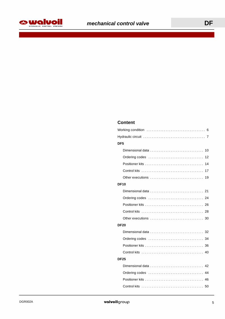
Content
Working condition 6. . . . . . . . . . . . . . . . . . . . . . . . . . . . . . . . . .
Hydraulic circuit 7. . . . . . . . . . . . . . . . . . . . . . . . . . . . . . . . . . . .
DF5
Dimensional data 10. . . . . . . . . . . . . . . . . . . . . . . . . . . . . . .
Ordering codes 12. . . . . . . . . . . . . . . . . . . . . . . . . . . . . . . .
Positioner kits 14. . . . . . . . . . . . . . . . . . . . . . . . . . . . . . . . . .
Control kits 17. . . . . . . . . . . . . . . . . . . . . . . . . . . . . . . . . . . .
Other executions 19. . . . . . . . . . . . . . . . . . . . . . . . . . . . . . .
DF10
Dimensional data 21. . . . . . . . . . . . . . . . . . . . . . . . . . . . . . .
Ordering codes 24. . . . . . . . . . . . . . . . . . . . . . . . . . . . . . . .
Positioner kits 26. . . . . . . . . . . . . . . . . . . . . . . . . . . . . . . . . .
Control kits 28. . . . . . . . . . . . . . . . . . . . . . . . . . . . . . . . . . . .
Other executions 30. . . . . . . . . . . . . . . . . . . . . . . . . . . . . . .
DF20
Dimensional data 32. . . . . . . . . . . . . . . . . . . . . . . . . . . . . . .
Ordering codes 34. . . . . . . . . . . . . . . . . . . . . . . . . . . . . . . .
Positioner kits 36. . . . . . . . . . . . . . . . . . . . . . . . . . . . . . . . . .
Control kits 40. . . . . . . . . . . . . . . . . . . . . . . . . . . . . . . . . . . .
DF25
Dimensional data 42. . . . . . . . . . . . . . . . . . . . . . . . . . . . . . .
Ordering codes 44. . . . . . . . . . . . . . . . . . . . . . . . . . . . . . . .
Positioner kits 46. . . . . . . . . . . . . . . . . . . . . . . . . . . . . . . . . .
Control kits 50. . . . . . . . . . . . . . . . . . . . . . . . . . . . . . . . . . . .

DF mechanical control valve
DGR002A6
DF5 DF10 DF20 DF25N. of available ways 2--3--6 2--3--6 2--3--6 3
Nominal flow rating 60 l/min16 US gpm
90 l/min24 US gpm
140 l/min37 US gpm
280 l/min74 US gpm
Operating pressure(maximum)
315 bar4600 psi
315 bar4600 psi
315 bar4600 psi
315 bar4600 psi
Internal leakage A(B)→T ∆p=100 bar 1450 psi with fuidand valve at 40°C − 104°F
5 cm3/min0.31 in3/min
5 cm3/min0.31 in3/min
8 cm3/min0.49 in3/min
8 cm3/min0.49 in3/min
Hydraulic fluid Mineral base oil
Fluid temperature with NBR seals from --20°C to 80°C / from --4°F to 176°F
with FPM seals from --20°C to 100°C / from --4°F to 212°F
Viscosity operating range from 15 to 75 mm2/s -- from 15 to 75 cSty
minimum 12 mm2/s -- 12 cSt
maximum 400 mm2/s -- 400 cSt
Max. level of contamination --/19/16 -- ISO 4406 / NAS 1638 -- class10
with mechanical control from --40°C to 60°C / from --40°F to 140°F
Ambient temperature forworking conditions
with hydraulic and pneumaticcontrols from --30°C to 60°C / from --22°F to 140°Fgwith electric controls from --20°C to 50°C / from --4°F to 122°F
NOTE -- For different working conditions please contact Sales Dept.
REFERENCE STANDARDS
BSP UN--UNF NPTF METRIC
THREADACCORDING TO
ISO 228/1 ISO 263 ANSI B1.20.3 ISO 262 ISO 262ACCORDING TO BS 2779 ANSI B1.1 unified
CAVITYACCORDING TO
ISO 1179 11926 9974--1 6149ACCORDING TO SAE J1926 J476a J2244
DIN 3852--2shape X or Y
3852--1shape X or Y
PORTS THREAD
ALL PORTS BSP UN--UNF METRIC(ISO 9974--1)
METRIC(ISO 6149)
DF5 G 3/8 3/4--16 (SAE 8) M18x1.5 M18x1.5
DF10 G 1/2 7/8--14 (SAE 10) M22x1.5
DF20 G 3/4 1 1/16--12 (SAE 12)
DF25 G 1 1 5/16--12 (SAE 16)
PILOT PORTS
Pneumatic NPT 1/8--27 NPT 1/8--27 NPT 1/8--27 NPT 1/8--27
Hydraulic G 1/4 9/16--18 (SAE 6)
Optional threads: for availability contactSales Department
Working conditions
This catalogue shows technical specifications and diagrams measured with mineral oil of 46 mm2/s -- 46 cSt viscosity at 40°C --
104°F temperature.
Standard threads

mechanical control valve DF
DGR002A 7
0
5
10
15
20
0 20 40 60 80
Flow
Pre
ssur
e
(bar)
(l/min)
Pressure drop versus flow
P→A
200
100
(psi)
5 10 15 (US gpm)20
Hydraulic circuit
2--wayAvailable as body only in DF5/2 execution; for other executions 3--way body is used.
Spool
Positioner kit Flange withdust--proof seal
1 2
A
P
Spool type A
1 2
A
P
Spool type B
Performance data
A
P

DF mechanical control valve
DGR002A8
0
5
10
15
20
0 90 180 270 360
Flow
Pre
ssur
e
(bar)
(l/min)
DF25/3
Spool B
(psi)
200
100
Spool A
30 60 90 (US gpm)
0
5
10
15
20
0 60 120 180
Flow
Pre
ssur
e
(bar)
(l/min)
DF20/3
Spool A(B)
(psi)
200
100
15 30 45 (US gpm)
0
5
10
15
20
0 30 60 90 120
Flow
Pre
ssur
e
(bar)
(l/min)
DF10/3
Spool A(B)
(psi)
200
100
10 20 30 (US gpm)
0
5
10
15
20
0 20 40 60 80
Flow
Pre
ssur
e
(bar)
(l/min)
DF5/3
Spool A
Spool B
(psi)
200
100
5 10 15 (US gpm)20
Hydraulic circuit
A
P
1 2
B
Spool type B BSpool type A
A
P
1 2
B
3--wayIt’s possible to obtain 2--way diverter valve plugging port A or B.
Performance data
Pressure drop versus flow: P→A(B)
A
P
B
mechanical control valve DF
DGR002A 9
0
5
10
15
20
0 60 120 180
Flow
Pre
ssur
e
(bar)
(l/min)
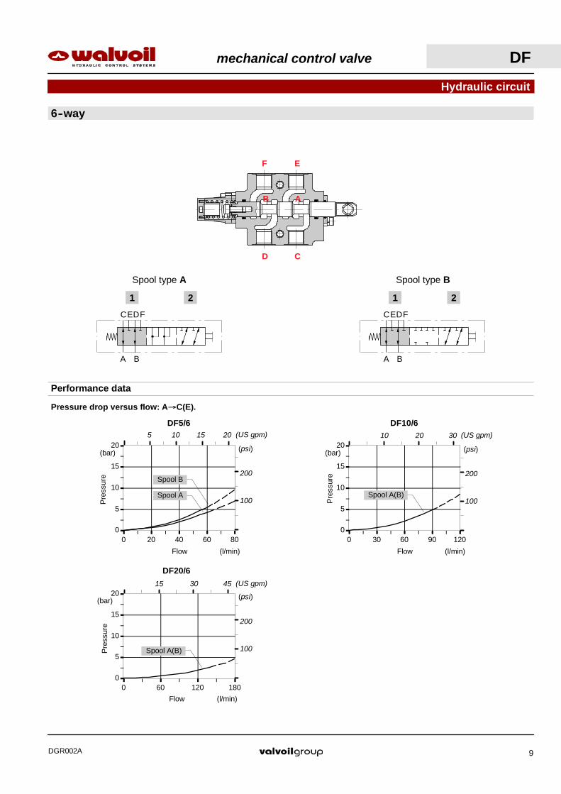
DF20/6
Spool A(B)
200
100
(psi)
15 30 45 (US gpm)
0
5
10
15
20
0 30 60 90 120
Flow
Pre
ssur
e
(bar)
(l/min)
DF10/6
Spool A(B)
200
100
(psi)
10 20 30 (US gpm)
0
5
10
15
20
0 20 40 60 80
Flow
Pre
ssur
e
(bar)
(l/min)
DF5/6
Spool A
Spool B200
100
(psi)
5 10 15 (US gpm)20
Hydraulic circuit
6--way
CE
1 2
A B
DF CE
1 2
A B
DF
Spool type A Spool type B
Performance data
Pressure drop versus flow: A→C(E).
F E
D C
B A

60
30
9
7841 25.5
153.5
22.5
4511
.5
68 A stroke = 11 mm / 0.43 in
*
2.68
0.06
0.89
6.04
1.61 3.07 1.00
2.36
1.18
0.35
32
16
20
4042
6.5
0.79
0.03
1.65
0.63
1.26
0.26n.3 holes
942
9
21
60
3825 941
9 38
72
25.5
147.5
A stroke = 11 mm / 0.43 in
*
2.36
1.65
0.83
0.35
0.35
2.84
0.35 1.50
5.81
1.61 0.98 1.50 0.35 1.00
20
4041.5
8.20.32
n.2 holes
0.79
1.57
1.63
Dimensional data
2--way DF5/2 valve
3--way DF5/3 valve
P
BA
BA
P
A
A
DF5 mechanical control valve
DGR002A10

26
5212
76
29.5 34
9341 25.5
168.5
46.5
A stroke = 11 mm / 0.43 in
*
2.05
1.02
0.47
2.99
1.83
1.61
1.16 1.34
1.003.66
6.63
20
34
55
6.52.
16
1.34
0.79
0.26n.2 holes
Dimensional data
6--way DF5/6 valve
15
4
21
1.5
x45
°
16
22
9 H8( 0+0,022)
8
Spool end
Standard end Spherical end type T
10.5
9.5
16
13
26.5
Rotary cam prearrangement16
M10
15
10.5
20
10.5
3
NOTE (*) -- With spool out(positioner kit type 17)
*
*0.87
0.83 0.06
x45
°
0.24
0.32
0.59
0.16
0.41
0.37 Wre
nch
100.
51
0.63
1.04
R 0.26Spherical
6.5--
0.79
0.59
0.12
0.41
0.41
0.63
0.35 ( 0+0.000866)
CD
EF
AB
CD
AB
mechanical control valve DF5
DGR002A 11

DF5 mechanical control valve
DGR002A12
SLCZ
4.
3.
1. 2. 3.
Description example:
4.
Ordering codes
1.
Diverter valve DF5/3 A 17 SLP -- SAE
2.
I
SLP
L
12
17
18P
3- way body
3- way spool
6- way body
6- way spool
2- way body
2- way spool

mechanical control valve DF5
DGR002A 13
I Optional handleverTYPE CODE DESCRIPTIONAL01/M8x120 170011012 For lever L: height 120 mm / 4.72 in1. Body kit *
TYPE CODE DESCRIPTIONDF5/6 5CO2222700 Standard body kit
Include body and seals
2. Spool optionsTYPE CODE DESCRIPTIONA 3CAS105610 6--way, 2 positions with ports connected
in transit positionB 3CAS105710 6--way, 2 positions with ports closed in
transit positionAC 3CAS105620 As type A prearranged for cam controlBC 3CAS105720 As type B prearranged for cam control
6- way
1. Body kit *TYPE CODE DESCRIPTIONDF5/3 5CO2221700 Standard body kit
Include body and seal
2. Spool optionsTYPE CODE DESCRIPTIONA 3CAS105310 3--way, 2 positions with ports connected
in transit positionB 3CAS105410 3--way, 2 positions with ports closed in
transit positionAT 3CAS105330 As type A with spherical endAC 3CAS105320 As type A prearranged for cam controlBC 3CAS105420 As type B prearranged for cam control
3- way
Ordering codes
NOTE (*) -- Codes are referred to UN- UNF thread.
3. Positioner kits page 14TYPE CODE DESCRIPTION12 5V12105000 Detent in positions 1 and 217 5V17105000 Spring return in position 117Y 5V17105010 As type 17, it must be coupled to IA2
control18ME 5V18405110 Spring return in position 218P 5V18105700 ON/OFF pneumatic kit with spring return
in position 2
18IA1 5V18105850* ON/OFF high pressure hydraulic kit withspring return in position 2
18IB1N 5V18105870* Comando idraulico a bassa pressione conritorno a molla in posizione 2
4. Control kits page 17TYPE CODE DESCRIPTIONSLP 5COP105000 Without lever box with dust--proof plate kitSLCZ 5COP205030 Without lever box with endcapTQ 5TEL105110 Flexible cable connectionL 5LEV105000 Standard kever boxCB 5CAM105020 Cam control
IA2 5IDR505700* ON/OFF high pressure hydraulic control
IB2 5IDR705700* ON/OFF low pressure hydraulic control
1. Kit corpo *TYPE BODY DESCRIPTIONDF5/2 5CO2220700 Standard body kit
Include body and seals
2. Spool optionsTYPE CODE DESCRIPTIONA 3CAS105210 2 positions with open centre in neutralB 3CAS105110 2 positions with closed centre in neutralAT 3CAS105230 As type A with spherical endBT 3CAS105130 As type B with spherical endAC 3CAS105220 As type A prearranged for cam controlBC 3CAS105120 As type B prearranged for cam control
2- way
411.61
--100
0
100
200
300
--12 --10 --8 --6 --4 --2 0Stroke
For
ce
(mm)
(N)
Force--Stroke diagram
--11
(in)
40
20
(lbf)--0.2--0.4
0
D
E
60
--20
--100
0
100
200
300
--12 --10 --8 --6 --4 --2 0Stroke
For
ce
(mm)
(N)
Force--Stroke diagram
--11
(in)
40
20
(lbf)--0.2--0.4
0
D
E
60
--20411.61
36.51.44
201
201
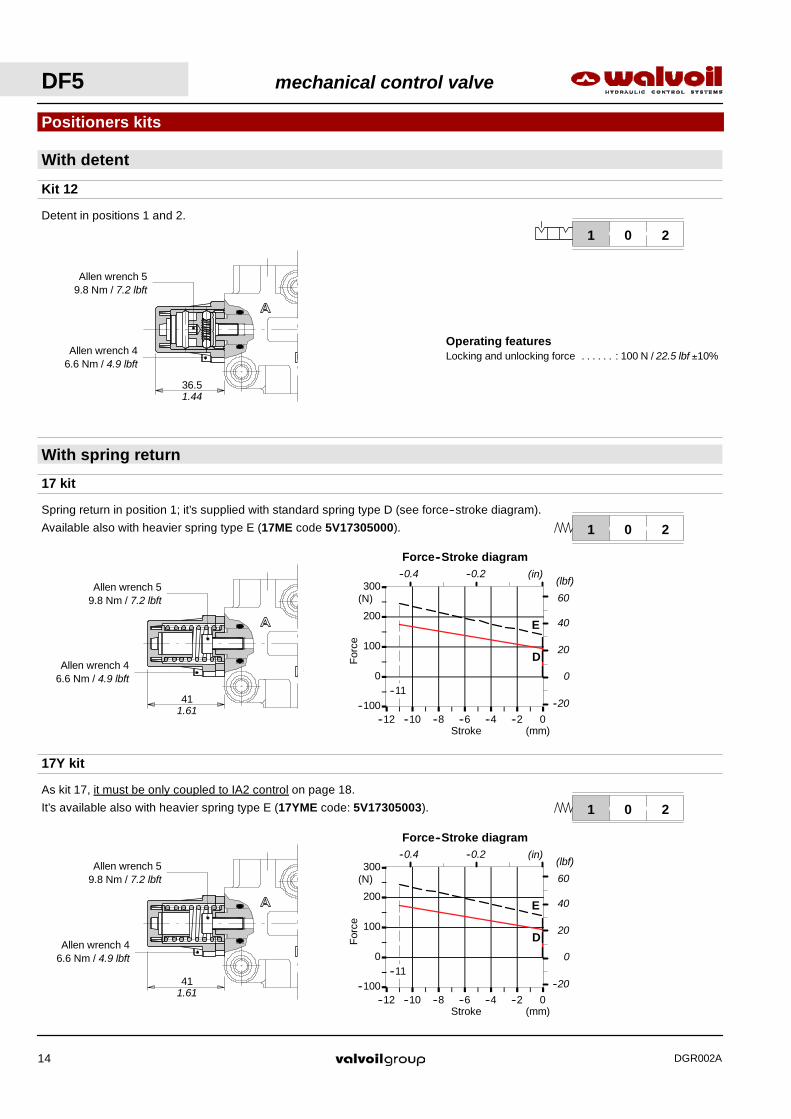
With detent
Positioners kits
Kit 12
17 kit
17Y kit
With spring return
201
Detent in positions 1 and 2.
Spring return in position 1; it’s supplied with standard spring type D (see force--stroke diagram).
Available also with heavier spring type E (17ME code 5V17305000).
As kit 17, it must be only coupled to IA2 control on page 18.
It’s available also with heavier spring type E (17YME code: 5V17305003).
Allen wrench 59.8 Nm / 7.2 lbft
Allen wrench 46.6 Nm / 4.9 lbft
Operating featuresLocking and unlocking force : 100 N / 22.5 lbf ±10%. . . . . .
Allen wrench 59.8 Nm / 7.2 lbft
Allen wrench 46.6 Nm / 4.9 lbft
Allen wrench 59.8 Nm / 7.2 lbft
Allen wrench 46.6 Nm / 4.9 lbft
DF5 mechanical control valve
DGR002A14

Operating featuresPilot pressure : min 6 bar / 87 psi. . . . . . . . . . . . . . . . .
max. 10 bar / 145 psi
118
V1NP
T1/
8”
Breather plugChiave 13 -- 9.8 Nm / 7.2 lbft
Wrench 1024 Nm / 17.7 lbft
Allen wrench 46.6 Nm / 4.9 lbft
Wrench 119.8 Nm / 7.2 lbft
Allen wrench 46.6 Nm / 4.9 lbft
4.65
53.52.11
--300
--200
--100
0
100
0 2 4 6 8 10 12Stroke
For
ce
(mm)
(N)
Force--Stroke diagram
11
(in)
(lbf)
0.2 0.4
--60
--30
0
18ME kit
201
Spring return in position 2.
ON/OFF pneumatic kit type 18P
Positioner kits
201
V1
With spring return in position 2.
With spring return
Allen wrench 59.8 Nm / 7.2 lbft
Allen wrench 46.6 Nm / 4.9 lbft
mechanical control valve DF5
DGR002A 15
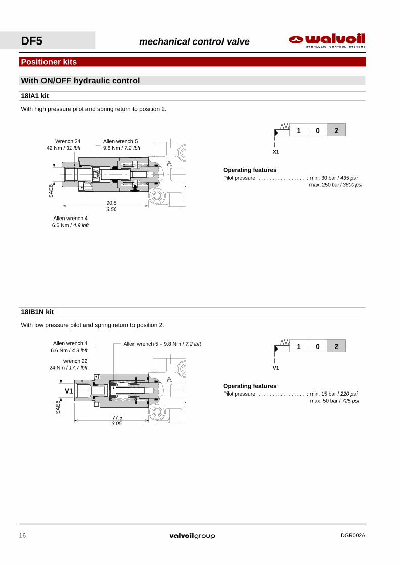
Operating featuresPilot pressure : min. 15 bar / 220 psi. . . . . . . . . . . . . . . . .
max. 50 bar / 725 psi
Operating featuresPilot pressure : min. 30 bar / 435 psi. . . . . . . . . . . . . . . . .
max. 250 bar / 3600 psi
18IA1 kit
Positioner kits
201
X1
With high pressure pilot and spring return to position 2.
X1
With ON/OFF hydraulic control
18IB1N kit
201
V1
With low pressure pilot and spring return to position 2.
77.5
V1
Allen wrench 46.6 Nm / 4.9 lbft
Allen wrench 5 -- 9.8 Nm / 7.2 lbft
90.53.56
Allen wrench 46.6 Nm / 4.9 lbft
SA
E6
Allen wrench 59.8 Nm / 7.2 lbft
Wrench 2442 Nm / 31 lbft
SA
E6
3.05
wrench 2224 Nm / 17.7 lbft
DF5 mechanical control valve
DGR002A16
20
44
20
53.7 65
.5
30
Allen wrench 46.6 Nm / 4.9 lbft
21Vertical handleverassembly
Horizontal handfleverassembly
15
0.79
2.11 2.
58
0.79
1.73
4
10.5
Allen wrench 46.6 Nm / 4.9 lbft
0.41
0.16
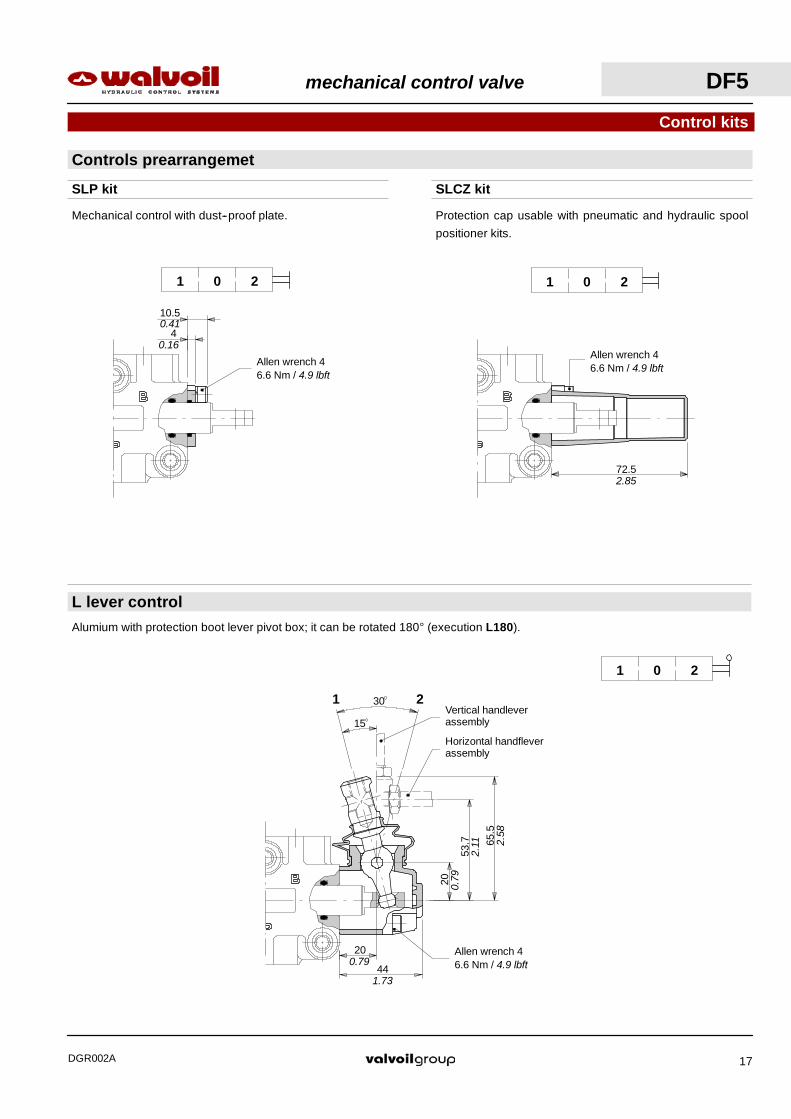
Controls prearrangemet
Control kits
SLP kit SLCZ kit
L lever control
72.5
201
201
201
Alumium with protection boot lever pivot box; it can be rotated 180° (execution L180).
Mechanical control with dust--proof plate. Protection cap usable with pneumatic and hydraulic spool
positioner kits.
Allen wrench 46.6 Nm / 4.9 lbft
2.85
mechanical control valve DF5
DGR002A 17
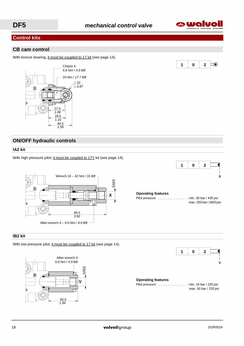
Operating featuresPilot pressure : min. 15 bar / 220 psi. . . . . . . . . . . . . . . . .
max. 50 bar / 725 psi
Operating featuresPilot pressure : min. 30 bar / 435 psi. . . . . . . . . . . . . . . . .
max. 250 bar / 3600 psi
27.5
29.5
40.5
22
Chiave 46.6 Nm / 4.9 lbft
24 Nm / 17.7 lbft
1.08
1.16
1.59
0.87
CB cam control
Control kits
ON/OFF hydraulic controls
With high pressure pilot; it must be coupled to 17Y kit (see page 14).
99.5
SA
E6
X
201
X
With bronze bearing; it must be coupled to 17 kit (see page 14).
201
IB2 kit
IA2 kit
With low pressure pilot; it must be coupled to 17 kit (see page 14).
201
V
50.5
Allen wrench 46.6 Nm / 4.9 lbft
SA
E6
V
Allen wrench 4 -- 6.6 Nm / 4.9 lbft
Wrench 24 -- 42 Nm / 31 lbft
3.92
1.99
DF5 mechanical control valve
DGR002A18

68
22.5
4511
.5
43.5
166.5
78
60
22
349
30
0.87
0.45
0.89
1.77
2.68
1.18
2.36 0.35 1.34
1.71 3.07
6.56
40
20
32
16
42
6.5n.3 holes0.26
1.65
1.57
0.79
0.63
1.26
Other executions
3--way DFC050/3 valve
Cam spool control suggested for severe applications; it requires a special body, spool and control kit.
A B
P
1 2
Spool type B
A
AA
Spool in rest positionP → B
Stroke limit = 11 mm / 0.43 in(full opening)
Stroke = 6.5 mm / 0.26 inP → A (start opening)
Performance data
0
4
8
12
0 20 40 60 80
Flow
Pre
ssur
e
(bar)
(l/min)
Pressure drop versus flow P→A(B)
0
100
200
300
400
500
0 2 4 6 8 10 12
Stroke
For
ce
(N)
(mm)
11
Operating force
120
80
40
(psi)160
90
60
30
(lbf)
1 2 3 (in)4
Valve is supplied painted as standard,with one coat of Primer black antirust paint
Complete description: DFC050/3B17GSLP--SAE--<CVN> code: 122050028
5 10 15 (US gpm)20
P
BA
BA
mechanical control valve DF5
DGR002A 19

34
17
9343.5
181.5
76 52
34
122.
99
2.05
0.47
1.71
0.67
1.22
3.66
7.15
1.34
55
20
34
22
6.5n.3 holes
2.16
1.34
0.79
0.26
0.87
0
4
8
12
0 20 40 60 80
Flow
Pre
ssur
e
(bar)
(l/min)
Pressure drop versus flow P→A(B)
0
100
200
300
400
500
0 2 4 6 8 10 12
Stroke
For
ce
(N)
(mm)
11
Operating force
120
80
40
(psi)160
90
60
30
(lbf)
1 2 3 (in)4
Other executions
6--way DFC050/6 valve
Spool in rest positionA → C / B → D
Performance data
A
AA Stroke limit = 11 mm / 0.43 in(full opening)
Stroke = 6.8 mm / 0.27 inA → E / B → F (start opening)
Spool type B
DF
1 2
B A
CE
Valve is supplied painted as standard,with one coat of Primer black antirust paint
Complete description: DFC050/6B17GSLP--SAE--<CVN> code: 122080019
5 10 15 (US gpm)20
CD
EF
AB
CD
AB
DF5 mechanical control valve
DGR002A20

18
36
22.5
4546.5
8.3 n.3 holes0.330.71
1.42
0.89
1.77
1.83
A stroke = 14 mm / 0.55 in
32.5
6510
51 85 43
190
25
5012
74
*
0.47
0.98
1.97
2.91
1.28
2.560.39
2.01 3.35 1.69
7.48
Dimensional data
3--way DF10/3 valve
P
BA
BA
mechanical control valve DF10
DGR002A 21
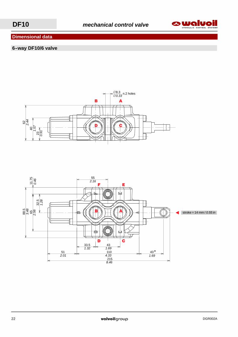
33.5 43
11051 43
215
32.5
6511
.75
88.5
55
*
0.46
1.28
2.563.48
2.16
1.32 1.69
2.01 4.33 1.69
8.46
23
40
62
8.3 n.2 holes∅
2.44
1.57
0.91
0.33∅
A stroke = 14 mm / 0.55 in
Dimensional data
6--way DF10/6 valve
CD
CD
EF
AB
AB
DF10 mechanical control valve
DGR002A22

NOTE (*) -- With spool out (positioner kit type 17)
Dimensional data
Spool end
5
18
10H8( 0+0,022)
10
20
1.5
x45°
27
32
Standard end Spherical end type T
16
19.5 20
R8Spherical
Wre
nch
14
11
12
Rotary cam prearragement
40
M12
12.5
20
24
3
22
30
*
*
1.26
1.060.
39
0.79
0.06
x45 °
0.71
0.20
0.43
0.47
1.57
R0.32
0.79
0.77
0.63
0.87
0.79
0.95
0.12
0.49
0.79
0.39 ( 0+0.000866)
mechanical control valve DF10
DGR002A 23
DF10 mechanical control valve
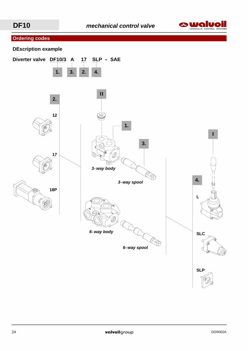
DGR002A24
3- way body
3- way spool
6- way body
6- way spool
Ordering codes
4.
2.
3.
I
SLP
SLC
L
12
17
18P
1. 3. 2.
DEscription example
4.
Diverter valve DF10/3 A 17 SLP -- SAE
II
1.

mechanical control valve DF10
DGR002A 25
I Optional handleverTYPE CODE DESCRIPTIONAL01/M10x200 170012020 For lever L, height 200 mm / 7.87 in
TYPE CODE DESCRIPTION
SAE10 3XTAP826160* Body conversion from 3--way to 2--waycircuit
II Ports plug
2. Positioner kits page 26
Ordering codes
1. Body kit *TYPE CODE DESCRIPTIONDF10/3 5CO2241700 Standard body kit
Include body and seals
3. Spool optionsTYPE CODE DESCRIPTIONA 3CAS110310 3--way, 2 positions with ports connected
in transit positionB 3CAS110410 3--way, 2 positions with ports closed in
transit positionAT 3CAS110330 As type A with spherical endAC 3CAS110320 As type A prearranged for cam controlBC 3CAS110420 As type B prearranged for cam control
TYPE CODE DESCRIPTION12 5V12110000 Detent in positions 1 and 217 5V17110000 Spring return in position 118 5V18110000 Spring return in position 218P 5V18110710 ON/OFF pneumatic kit with spring return
in position 2
18IA1 5V18110850* ON/OFF high pressure hydraulic kit withspring return in position 2
18IB1 5V18110870* ON/OFF low pressure hydraulic kit withspring return in position 2
4. Control kits page 28TYPE CODE DESCRIPTIONSLP 5COP110000 Without lever box with dust--proof plate kitSLC 5COP210000 Without lever box with endcapL 5LEV110000 Standard lever boxCB 5CAM110020 Cam control
IA2 5IDR510701* ON/OFF high pressure hydraulic control
IB2 5IDR710700* ON/OFF low pressure hydraulic control
3- way
1. Body kit *TYPE CODE DESCRIPTIONDF10/6 5CO2242700 Standard body kit
Include body and seals
3. Spool optionsTYPE CODE DESCRIPTIONA 3CAS110610 6--way, 2 positions with ports connected
in transit positionsB 3CAS110710 6--way, 2 positions with ports colosed in
transit positionsAC 3CAS110620 As type A prearranged for cam controlBC 3CAS110720 As type B prearranged for cam control
6- way
NOTE (*) -- Codes are referred to UN- UNF thread.

Operating featuresLocking and unlocking force : 280 N / 63 lbf ±10%. . . . . . .
512.01
--400
--200
0
200
0 2 4 6 8 10 12 14Stroke
For
ce
(mm)
(N)
Force--Stroke diagram
(in)
(lbf)
0.2 0.4
80
40
0
--40
--200
0
200
400
--14 --12 --10 --8 --6 --4 --2 0Stroke
For
ce
(mm)
(N)
Force--Stroke diagram
(in)
80
40
(lbf)--0.2--0.4
0
--4051
2.01
512.01
201
With detent
Positioner kits
17 kit
18 kit
With spring return
201
201
Spring return in position 1.
Spring return in position 2.
12 kit
Detent in positions 1 and 2.
Allen wrench 5 -- 9.8 Nm / 7.2 lbft
Allen wrench 624 Nm / 17.7 lbft
Allen wrench 5 -- 9.8 Nm / 7.2 lbft
Allen wrench 624 Nm / 17.7 lbft
Allen wrench 5 -- 9.8 Nm / 7.2 lbft
Allen wrench 624 Nm / 17.7 lbft
DF10 mechanical control valve
DGR002A26
133
139
NP
T1/
8”
V1
Allen wrench 5 -- 9.8 Nm / 7.2 lbft
24 Nm / 17.7 lbft
Chiave 59.8 Nm / 7.2 lbft
Wrench 13 -- 24 Nm / 17.7 lbft
Wrench 13
Breather plugChiave 13 -- 9.8 Nm / 7.2 lbft
5.24
5.47
973.82
SA
E6
X1
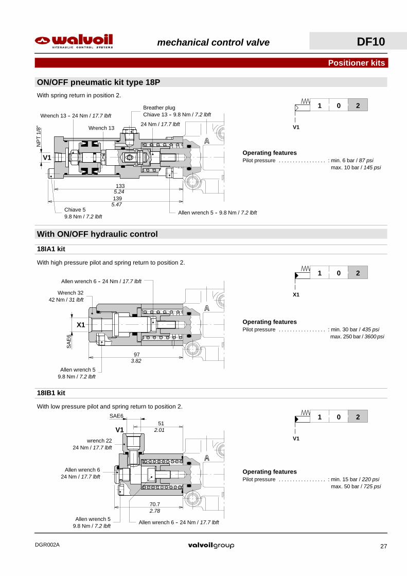
Operating featuresPilot pressure : min. 15 bar / 220 psi. . . . . . . . . . . . . . . . .
max. 50 bar / 725 psi
Operating featuresPilot pressure : min. 30 bar / 435 psi. . . . . . . . . . . . . . . . .
max. 250 bar / 3600 psi
Operating featuresPilot pressure : min. 6 bar / 87 psi. . . . . . . . . . . . . . . . .
max. 10 bar / 145 psi
ON/OFF pneumatic kit type 18P
Positioner kits
With ON/OFF hydraulic control
201
V1
With spring return in position 2.
201
X1
With high pressure pilot and spring return to position 2.
Allen wrench 6 -- 24 Nm / 17.7 lbft
18IA1 kit
18IB1 kit
201
V1
With low pressure pilot and spring return to position 2.
70.7
V1
Allen wrench 624 Nm / 17.7 lbft
Allen wrench 6 -- 24 Nm / 17.7 lbftAllen wrench 5
9.8 Nm / 7.2 lbft
51
Wrench 3242 Nm / 31 lbft
Allen wrench 59.8 Nm / 7.2 lbft
2.78
2.01
wrench 2224 Nm / 17.7 lbft
SAE6
mechanical control valve DF10
DGR002A 27
24
65.5 77
.5
36
67.5
3221
Vertical handleverassembly
Horizontal handleverassembly
Allen wrench 59.8 Nm / 7.2 lbft
0.95
2.58 3.
05
1.42
2.66
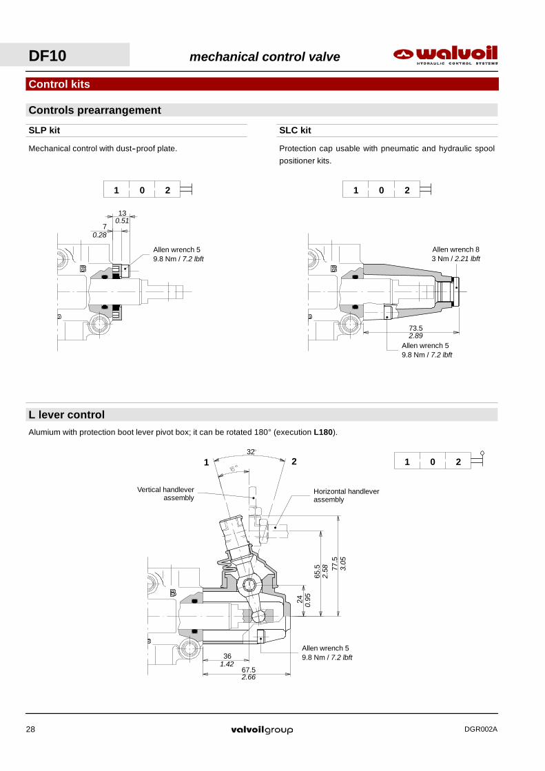
SLC kit
Allen wrench 59.8 Nm / 7.2 lbft
201
73.5
Allen wrench 83 Nm / 2.21 lbft
Protection cap usable with pneumatic and hydraulic spool
positioner kits.
2.89
SLP kit
201
7
13
Allen wrench 59.8 Nm / 7.2 lbft
Mechanical control with dust--proof plate.
0.28
0.51
Controls prearrangement
Control kits
L lever control
201
Alumium with protection boot lever pivot box; it can be rotated 180° (execution L180).
DF10 mechanical control valve
DGR002A28
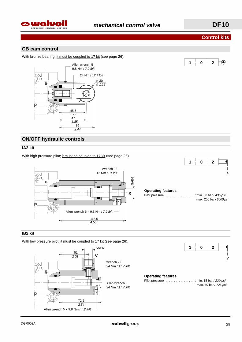
Operating featuresPilot pressure : min. 15 bar / 220 psi. . . . . . . . . . . . . . . . .
max. 50 bar / 725 psi
Operating featuresPilot pressure : min. 30 bar / 435 psi. . . . . . . . . . . . . . . . .
max. 250 bar / 3600 psi
115.5
X
4.55
45.5
47
62
30
Allen wrench 59.8 Nm / 7.2 lbft
24 Nm / 17.7 lbft
1.79
1.85
2.44
1.18
CB cam control
Control kits
ON/OFF hydraulic controls
With bronze bearing; it must be coupled to 17 kit (see page 26).
201
201
X
With high pressure pilot; it must be coupled to 17 kit (see page 26).
IA2 kit
201
V
With low pressure pilot; it must be coupled to 17 kit (see page 26).
IB2 kit
72.2
V51
Allen wrench 624 Nm / 17.7 lbft
2.01
2.84Allen wrench 5 -- 9.8 Nm / 7.2 lbft
Wrench 3242 Nm / 31 lbft
Allen wrench 5 -- 9.8 Nm / 7.2 lbft
SA
E6
SAE6
wrench 2224 Nm / 17.7 lbft
mechanical control valve DF10
DGR002A 29
57 48
37
85
190
65
32.5
76 5013
25
22
0.51
2.99 50 1.97
0.98
2.24
1.28
2.56
3.35
7.48
1.46
1.89
0.87
18
36
46.5
45
22.5
8.3n.3 holes
1.42
0.71
1.83
1.77
0.89
0.33
0
100
200
300
400
500
0 2 4 6 8 10 12 140
4
8
12
0 30 60 90 120
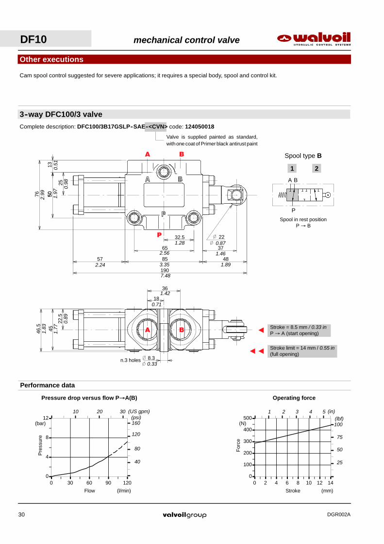
Other executions
3--way DFC100/3 valve
A B
P
1 2
Spool type B
Spool in rest positionP → B
Performance data
Flow
Pre
ssur
e
(bar)
(l/min)
Pressure drop versus flow P→A(B)
Stroke
For
ce
(N)
(mm)
Operating force
A
AAStroke limit = 14 mm / 0.55 in(full opening)
Stroke = 8.5 mm / 0.33 inP → A (start opening)
Cam spool control suggested for severe applications; it requires a special body, spool and control kit.
120
80
40
(psi)160
(lbf)1 2 3 (in)4 5
75
50
25
100
Valve is supplied painted as standard,with one coat of Primer black antirust paint
Complete description: DFC100/3B17GSLP--SAE--<CVN> code: 124050018
(US gpm)10 20 30
P
BA
BA
DF10 mechanical control valve
DGR002A30
43
62
40
23
21.5
22
2.44
1.57
0.91
0.85
1.69
0.87
8.3 n.2 holes0.33
57 48
37
110
215
43
21.5
88.5
65
8.5n.2 holes
3.48
2.56
0.33
0.85
1.69
2.24 4.33
8.46
1.46
1.89
A
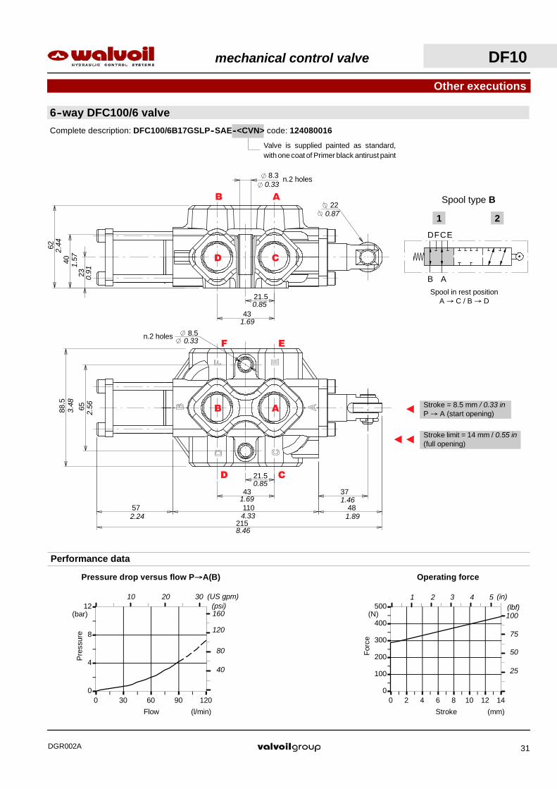
AAStroke limit = 14 mm / 0.55 in(full opening)
Stroke = 8.5 mm / 0.33 inP → A (start opening)
0
100
200
300
400
500
0 2 4 6 8 10 12 140
4
8
12
0 30 60 90 120
Flow
Pre
ssur
e
(bar)
(l/min)
Pressure drop versus flow P→A(B)
Stroke
For
ce
(N)
(mm)
Operating force
120
80
40
(psi)160
(lbf)1 2 3 (in)4 5
75
50
25
100
Other executions
6--way DFC100/6 valve
Performance data
Spool in rest positionA → C / B → D
Spool type B
DF
1 2
B A
CE
Valve is supplied painted as standard,with one coat of Primer black antirust paint
Complete description: DFC100/6B17GSLP--SAE--<CVN> code: 124080016
10 20 30 (US gpm)
CD
EF
AB
CD
AB
mechanical control valve DF10
DGR002A 31

26
52
27.5
5557
10.2n.3 holes
1.08
2.16
2.24
1.02
2.05
0.41
A Stroke =20 mm / 0.79 in
42.5
8512.5
61 110 55
238
30
6012
.5
85
*
1.18
0.49
2.36
3.35
2.16
1.67
0.49 3.35
4.33
9.37
2.40
Dimensional data
3--way DF20/3 valve
P
BA
BA
DF20 mechanical control valve
DGR002A32
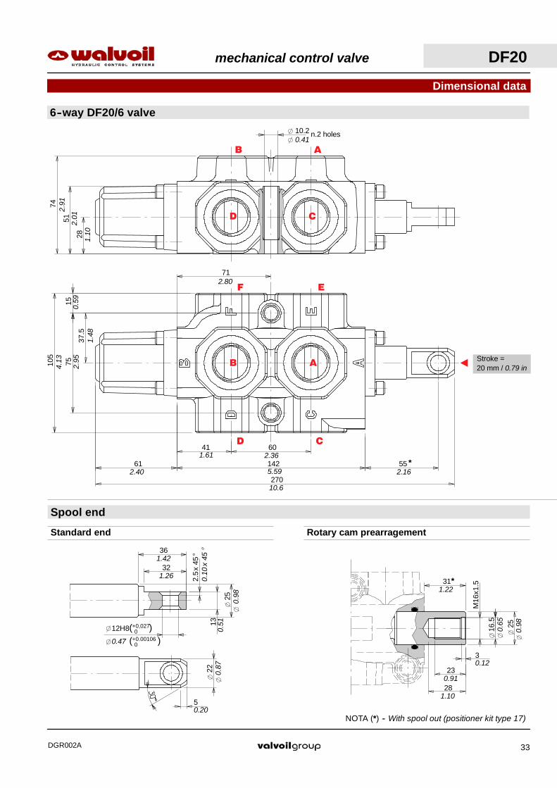
A Stroke =20 mm / 0.79 in
41 60
14261 55
270
37.5
7515
105
71
*
2.80
4.13
0.59
1.48
2.95
2.40 5.59
10.6
2.361.61
2.16
10.2 n.2 holes
28
51
74
1.10
2.01
2.91
0.41
30.12
Dimensional data
6--way DF20/6 valve
Spool end
5
22
2.5
x45
°
13
12H8( 0+0,027)
25
32
36
Standard end Rotary cam prearragement
M16
x1.5
25
23
16.5
31
28
*
NOTA (*) -- With spool out (positioner kit type 17)
1.26
1.42
0.51
0.10
x45
°
0.98
0.87
0.20
1.22
1.10
0.91
0.65
0.98
0.47 ( 0+0.00106 )
CD
EF
AB
CD
AB
mechanical control valve DF20
DGR002A 33

DF20 mechanical control valve
DGR002A34
1. 3. 2.
Description example
4.
Ordering codes
Diverter valve DF20/3 A 17 SLP -- SAE
4.
2.
3.
I
SLP
SLC
L
12
17
18P
3- way body
3- way spool
6- way body
6- way spool
II
1.
mechanical control valve DF20
DGR002A 35
TYPE CODE DESCRIPTION
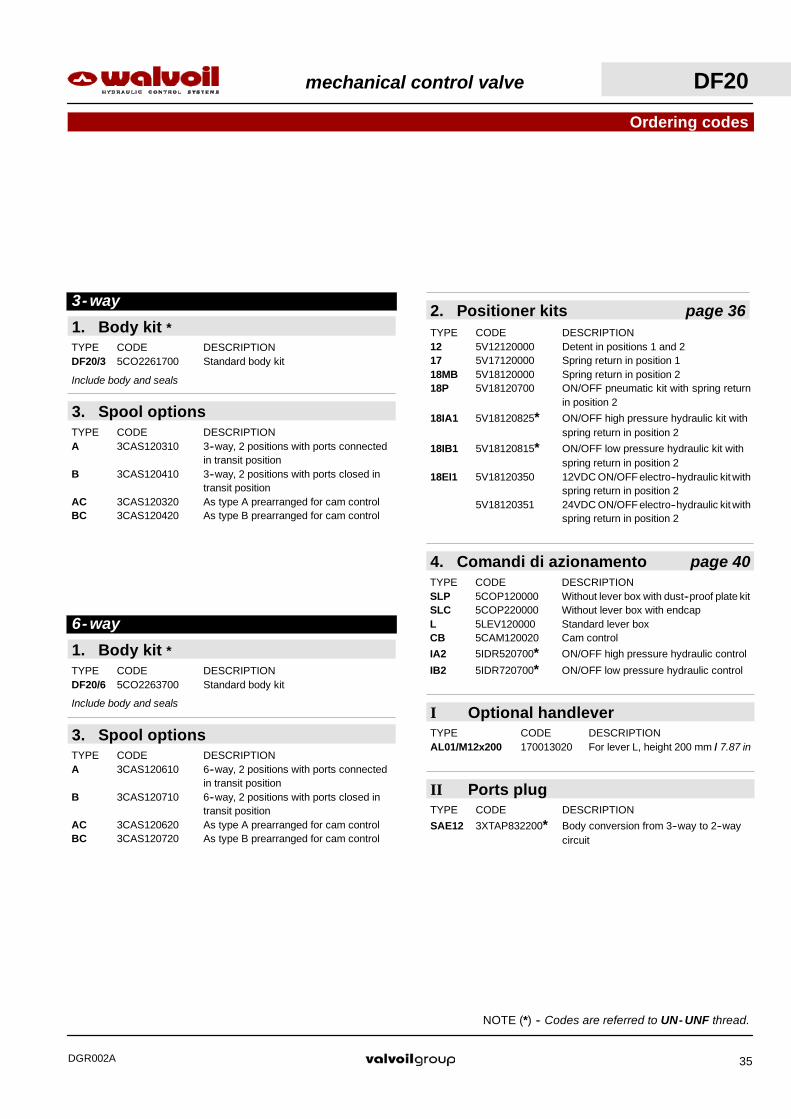
SAE12 3XTAP832200* Body conversion from 3--way to 2--waycircuit
II Ports plug
I Optional handleverTYPE CODE DESCRIPTIONAL01/M12x200 170013020 For lever L, height 200 mm / 7.87 in
1. Body kit *TYPE CODE DESCRIPTIONDF20/3 5CO2261700 Standard body kit
Include body and seals
3. Spool optionsTYPE CODE DESCRIPTIONA 3CAS120310 3--way, 2 positions with ports connected
in transit positionB 3CAS120410 3--way, 2 positions with ports closed in
transit positionAC 3CAS120320 As type A prearranged for cam controlBC 3CAS120420 As type B prearranged for cam control
3- way
1. Body kit *TYPE CODE DESCRIPTIONDF20/6 5CO2263700 Standard body kit
Include body and seals
3. Spool optionsTYPE CODE DESCRIPTIONA 3CAS120610 6--way, 2 positions with ports connected
in transit positionB 3CAS120710 6--way, 2 positions with ports closed in
transit positionAC 3CAS120620 As type A prearranged for cam controlBC 3CAS120720 As type B prearranged for cam control
6- way
Ordering codes
NOTE (*) -- Codes are referred to UN- UNF thread.
2. Positioner kits page 36TYPE CODE DESCRIPTION12 5V12120000 Detent in positions 1 and 217 5V17120000 Spring return in position 118MB 5V18120000 Spring return in position 218P 5V18120700 ON/OFF pneumatic kit with spring return
in position 2
18IA1 5V18120825* ON/OFF high pressure hydraulic kit withspring return in position 2
18IB1 5V18120815* ON/OFF low pressure hydraulic kit withspring return in position 2
18EI1 5V18120350 12VDC ON/OFF electro--hydraulic kit withspring return in position 2
5V18120351 24VDC ON/OFF electro--hydraulic kit withspring return in position 2
4. Comandi di azionamento page 40TYPE CODE DESCRIPTIONSLP 5COP120000 Without lever box with dust--proof plate kitSLC 5COP220000 Without lever box with endcapL 5LEV120000 Standard lever boxCB 5CAM120020 Cam control
IA2 5IDR520700* ON/OFF high pressure hydraulic control
IB2 5IDR720700* ON/OFF low pressure hydraulic control

Operating featuresLocking and unlocking force : 420 N / 94.4 lbf ±10%. . . . . .
--400
--200
0
200
0 5 10 15 20Stroke
For
ce
(mm)
(N)
Force--stroke diagram
(lbf)
--80
--40
0
40
(in)--0.3 --0.6
612.40
--200
0
200
400
--20 --15 --10 --5 0Stroke
For
ce
(mm)
(N)
Force--Stroke diagram
(in)
80
40
(lbf)--0.3--0.6
0
--4061
2.40
612.40
Positioner kit
17 kit
18MB kit
With spring return
201
201
Spring return in position 1.
Spring return in position 2.
201
With detent
12 kit
Detent in positions 1 and 2.
Allen wrench 5 -- 9.8 Nm / 7.2 lbft
Allen wrench 824 Nm / 17.7 lbft
Allen wrench 5 -- 9.8 Nm / 7.2 lbft
Allen wrench 824 Nm / 17.7 lbft
Allen wrench 5 -- 9.8 Nm / 7.2 lbft
Allen wrench 824 Nm / 17.7 lbft
DF20 mechanical control valve
DGR002A36

Operating featuresPilot pressure : min. 15 bar / 220 psi. . . . . .
max. 50 bar / 725 psi
Operating featuresPilot pressure : min. 30 bar / 435 psi. . . . . .
max. 250 bar / 3600 psi
Allen wrench 5 -- 9.8 Nm / 7.2 lbft
Operating featuresPilot pressure : min. 6 bar / 87 psi. . . . . .
max. 10 bar / 145 psi
164.5
170.56.48
6.71
With ON/OFF hydraulic control
ON/OFF pneumatic kit type 18P
Positioner kits
201
V1
With spring return in position 2.
201
X1
With high pressure pilot and spring return to position 2.
NP
T1/
8”
V1
117
X1
Allen wrench 5 -- 9.8 Nm / 7.2 lbft
Wrench 16 -- 24 Nm / 17.7 lbft
Wrench 13
Breather plugWrench 13 -- 9.8 Nm / 7.2 lbft
18IA1 kit
18IB1 kit
201
V1
With low pressure pilot and spring return to position 2.
82.5
V1
Allen wrench 59.8 Nm / 7.2 lbft
24 Nm / 17.7 lbft
4.61
Allen wrench 824 Nm / 17.7 lbft
3.25
Allen wrench 59.8 Nm / 7.2 lbft
Wrench 32 -- 42 Nm / 31 lbft
SA
E6
SAE662
2.44
wrench 2224 Nm / 17.7 lbft
Allen wrench 624 Nm / 17.7 lbft
Allen wrench 824 Nm / 17.7 lbft
mechanical control valve DF20
DGR002A 37
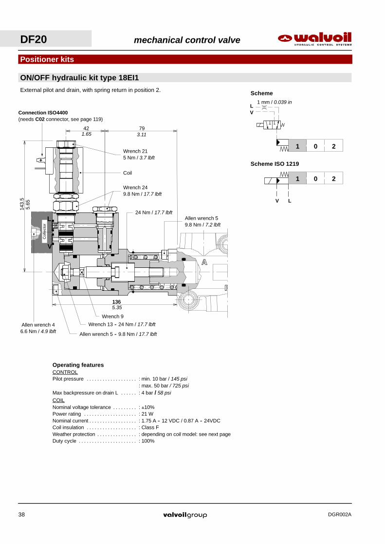
Operating featuresCONTROLPilot pressure : min. 10 bar / 145 psi. . . . . . . . . . . . . . . . . . .
: max. 50 bar / 725 psiMax backpressure on drain L : 4 bar / 58 psi. . . . . .COILNominal voltage tolerance : ±10%. . . . . . . . .Power rating : 21 W. . . . . . . . . . . . . . . . . . . .Nominal current : 1.75 A -- 12 VDC / 0.87 A -- 24VDC. . . . . . . . . . . . . . . . . .Coil insulation : Class F. . . . . . . . . . . . . . . . . . .Weather protection : depending on coil model: see next page. . . . . . . . . . . . . . .Duty cycle : 100%. . . . . . . . . . . . . . . . . . . . . .
79421.65 3.11
Col
lect
or
ON/OFF hydraulic kit type 18EI1
Positioner kits
136
143.
5
External pilot and drain, with spring return in position 2.
Scheme ISO 1219
Scheme
201
201
V L
LV
V
L
Wrench 9
Allen wrench 59.8 Nm / 7.2 lbft
24 Nm / 17.7 lbft
Connection ISO4400(needs C02 connector, see page 119)
Wrench 249.8 Nm / 17.7 lbft
Coil
1 mm / 0.039 in
Wrench 215 Nm / 3.7 lbft
1365.35
5.65
Wrench 13 -- 24 Nm / 17.7 lbft
Allen wrench 5 -- 9.8 Nm / 17.7 lbft
Allen wrench 46.6 Nm / 4.9 lbft
DF20 mechanical control valve
DGR002A38

L
Allen wrench 624 Nm / 17.7 lbft
SAE632
136
66
23
23
45
V
Allen wrench 624 Nm / 17.7 lbft
SAE6
5.35
0.91
1.26 0.91
1.77
2.60
147.
5
159
27
54
93
19.5
V20 bar
290 psi
L
Collectortype : KE1S0
code: 5KE1S00070
5.81
6.26
0.77
1.06
2.13
3.66Wrench 22
24 Nm / 17.7 lbft
ON/OFF hydraulic kit type 18EI1
Positioner kits
Collector kit for external pilot and drain
Description example:
DF20/3A18EI1SLC/SAE--KE1S0--12VDC
Coil withISO4400 connection
(weather protection IP65)
Coil withAMP JPT connection
(weather protection IP65)
Coil with Deutsch DT connection(weather protection IP67)
145
100
5.71
4.08
mechanical control valve DF20
DGR002A 39
COIL CODES
CONNECTION TYPE
ISO4400AMP JPT
Deutsch DTVoltage
ISO4400without diode with diode
Deutsch DT
12 VDC 2XB1400121100 2XB1400121200 2XB1400121210 2XB1400120400
24 VDC 2XB1400241100 2XB1400241200 2XB1400241210 2XB1400240400
Needconnector type
(page 119)C02 C08 C08 C19
Vertical handleverassembly
Horizontal handleverassembly
Allen wrench 69.8 Nm / 7.2 lbft
21
45
77
29
74.5 89
38
19
2.93
1.14
3.50
1.77
3.03
Allen wrench 69.8 Nm / 7.2 lbft
7
14.5
0.28
0.57
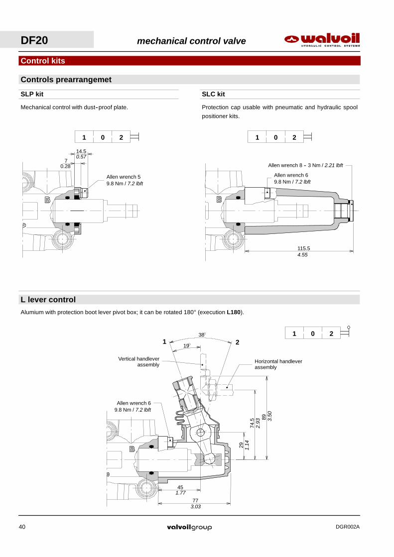
Controls prearrangemet
Control kits
SLP kit SLC kit
L lever control
201
201
201
Alumium with protection boot lever pivot box; it can be rotated 180° (execution L180).
Mechanical control with dust--proof plate. Protection cap usable with pneumatic and hydraulic spool
positioner kits.
Allen wrench 59.8 Nm / 7.2 lbft
115.5
Allen wrench 8 -- 3 Nm / 2.21 lbft
4.55
DF20 mechanical control valve
DGR002A40

Operating featuresPilot pressure : min. 15 bar / 220 psi. . . . . .
max. 50 bar / 725 psi
Operating featuresPilot pressure : min. 30 bar / 435 psi. . . . . .
max. 250 bar / 3600 psi
CB cam control
Control kits
With bronze bearing; it must be coupled to 17 kit (see page 36).
201
201
X
With high pressure pilot; it must be coupled to 17 kit (see page 36).
X
139.5
ON/OFF hydraulic controls
IA2 kit
IB2 kit
With low pressure pilot; it must be coupled to 17 kit (see page 36).
201
V
Allen wrench 5 -- 9.8 Nm / 7.2 lbft
84.5
65V
Allen wrench 624 Nm / 17.7 lbft
Allen wrench 59.8 Nm / 7.2 lbft
35
54
59
77
1.38
2.13
2.32
3.03
24 Nm / 17.7 lbft
5.49
2.56
3.33
Allen wrench 5 -- 9.8 Nm / 7.2 lbft
Wrench 32 -- 42 Nm / 31 lbft
SA
E6
wrench 2224 Nm / 17.7 lbft
SAE6
mechanical control valve DF20
DGR002A 41
28
56
33
6668
10.5 n.3 holes
1.10
0.412.20
1.30
2.60
2.68
45
9015
120 5581
268
35
7017
104
*
4.09
2.76
0.67
1.38
1.77
3.540.59
3.19 4.72
10.6
2.16
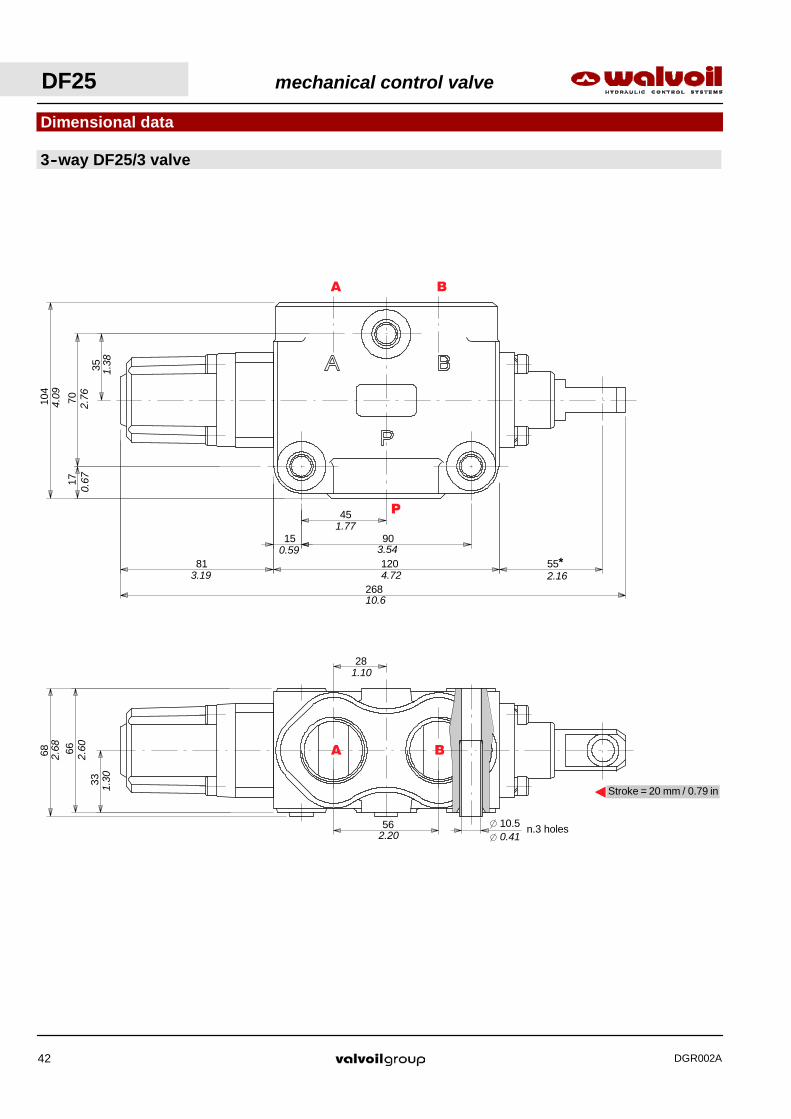
Dimensional data
3--way DF25/3 valve
AStroke = 20 mm / 0.79 in
P
BA
BA
DF25 mechanical control valve
DGR002A42

Rotary cam prearragement
M16
x1.5
30
24
16.5
31
30
3
*1.22
0.65
1.18
0.12
0.95
1.18
Standard end
2.5 x 45°
12H8( 0+0 )
13
30,027
22
5
32
38
0.10 x 45° 0.51
1.18
1.50
1.26
0.87
0.20
0.47 ( 0+0.00106)
Dimensional data
Spool end
NOTA (*) -- With spool out (positioner kit type 17)
mechanical control valve DF25
DGR002A 43
DF25 mechanical control valve
DGR002A44
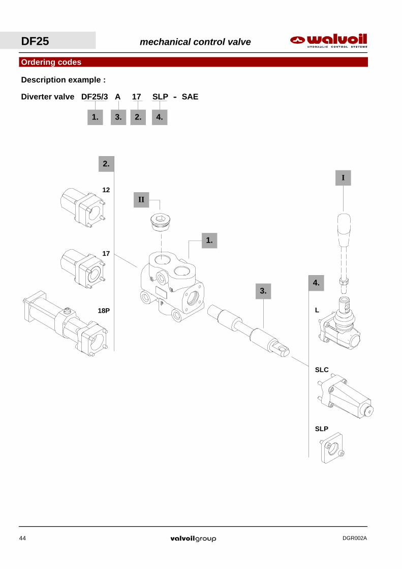
1. 3. 2.
Description example :
4.
Ordering codes
Diverter valve DF25/3 A 17 SLP -- SAE
4.
2.
3.
I
SLP
SLC
L
12
17
18P
II
1.

mechanical control valve DF25
DGR002A 45
TYPE CODE DESCRIPTION
SAE16 3XTAP838200* Body conversion from 3--way to 2--waycircuit
II Ports plug
I Optional handleverTYPE CODE DESCRIPTIONAL01/M12x200 170013020 For lever L, height 200 mm / 7.87 in
Ordering codes
NOTE (*) -- Codes are referred to UN- UNF thread.
2. Positioner kits page 46TYPE CODE DESCRIPTION12 5V12125000 Detent in positions 1 and 217 5V17125000 Spring return in position 118P 5V18125700 ON/OFF pneumatic kit with spring return
in position 218EI1 5V18125350 12VDC ON/OFF electro--hydraulic kit with
spring return in position 25V18125351 24VDC ON/OFF electro--hydraulic kit with
spring return in position 2
4. Control kits page 50TYPE CODE DESCRIPTIONSLP 5COP125000 Without lever box with dust--proof plate kitSLC 5COP220000 Without lever box with endcapL 5LEV120000 Standard lever boxCB 5CAM125020 Cam control
IA2 5IDR520700* ON/OFF high pressure hydraulic control
IB2 5IDR720700* ON/OFF low pressure hydraulic control
1. Body kit *TYPE CODE DESCRIPTIONDF25/3 5CO2271700 Standard body kit
Include body and seals
3. Spool optionsTIPO CODICE DESCRIZIONEA 3CAS125310 3--way, 2 positions with ports connected
in transit positionB 3CAS125410 3--way, 2 positions with ports closed in
transit positionAC 3CAS125320 As type A prearranged for cam controlBC 3CAS125420 As type B prearranged for cam control
3- way
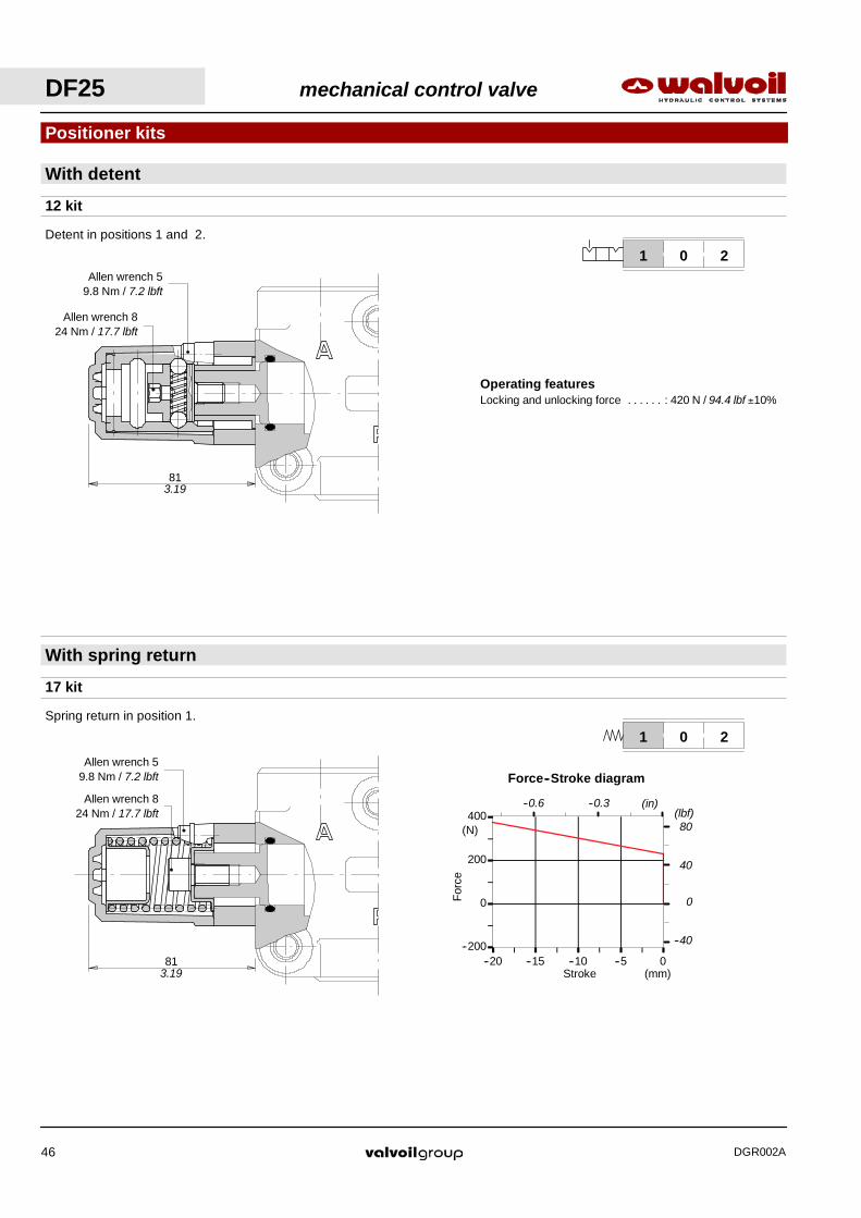
Operating featuresLocking and unlocking force : 420 N / 94.4 lbf ±10%. . . . . .
--200
0
200
400
--20 --15 --10 --5 0Stroke
For
ce
(mm)
(N)
Force--Stroke diagram
(in)
80
40
(lbf)--0.3--0.6
0
--40
Allen wrench 59.8 Nm / 7.2 lbft
Allen wrench 824 Nm / 17.7 lbft
813.19
With spring return
17 kit
Spring return in position 1.
201
Positioner kits
201
With detent
12 kit
Detent in positions 1 and 2.
Allen wrench 59.8 Nm / 7.2 lbft
81
Allen wrench 824 Nm / 17.7 lbft
3.19
DF25 mechanical control valve
DGR002A46

190.5
NP
T1/
8”
184.5
7.50
7.26
Operating featuresPilot pressure : min 7 bar / 102 psi. . . . . . . . . . . . . . . . .
max. 10 bar / 145 psi
ON/OFF pneumatic kit type 18P
Positioner kits
201
V1
With spring return in position 2.
V1
Allen wrench 59.8 Nm / 7.2 lbft
24 Nm / 17.7 lbft
Allen wrench 59.8 Nm / 7.2 lbft
Wrench 1624 Nm / 17.7 lbft
Wrench 13
Breather plugWrench 13 -- 9.8 Nm / 7.2 lbft
mechanical control valve DF25
DGR002A 47
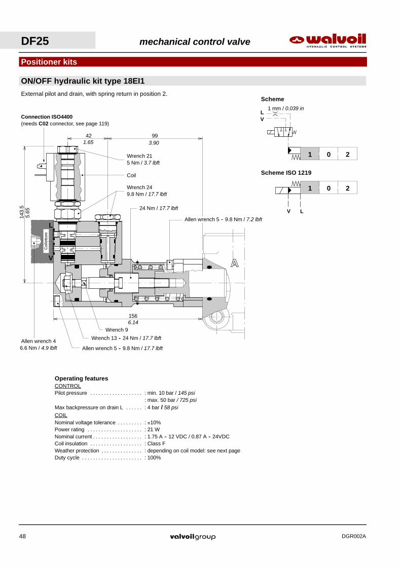
Operating featuresCONTROLPilot pressure : min. 10 bar / 145 psi. . . . . . . . . . . . . . . . . . .
: max. 50 bar / 725 psiMax backpressure on drain L : 4 bar / 58 psi. . . . . .COILNominal voltage tolerance : ±10%. . . . . . . . .Power rating : 21 W. . . . . . . . . . . . . . . . . . . .Nominal current : 1.75 A -- 12 VDC / 0.87 A -- 24VDC. . . . . . . . . . . . . . . . . .Coil insulation : Class F. . . . . . . . . . . . . . . . . . .Weather protection : depending on coil model: see next page. . . . . . . . . . . . . . .Duty cycle : 100%. . . . . . . . . . . . . . . . . . . . . .
Scheme ISO 1219
Scheme
201
201
V L
LV
1 mm / 0.039 in
ON/OFF hydraulic kit type 18EI1
Positioner kits
External pilot and drain, with spring return in position 2.
156
143.
5
9942
Col
letto
re
V
L
Connection ISO4400(needs C02 connector, see page 119)
Allen wrench 5 -- 9.8 Nm / 7.2 lbft
24 Nm / 17.7 lbft
Wrench 249.8 Nm / 17.7 lbft
Coil
Wrench 215 Nm / 3.7 lbft
1.65 3.90
6.14Wrench 9
Wrench 13 -- 24 Nm / 17.7 lbft
Allen wrench 5 -- 9.8 Nm / 17.7 lbftAllen wrench 46.6 Nm / 4.9 lbft
5.65
DF25 mechanical control valve
DGR002A48

L
SAE6Allen wrench 624 Nm / 17.7 lbft 32
156
66
23
23
45
V
Allen wrench 624 Nm / 17.7 lbft
sAE6
2.60
1.77
6.14
0.91
1.26 0.91
167.
5
179
V L20 bar
290 psi
6.59 7.05
27
54
93
19.50.77
1.06
2.13
3.66Wrench 22
24 Nm / 17.7 lbft
ON/OFF hydraulic kit type 18EI1
Positioner kits
Collector kit for external pilot and drain
Description example:
DF25/3A18EI1SLC/SAE--KE1S0--12VDC
Coil withISO4400 connection
(weather protection IP65)
Coil withAMP JPT connection
(weather protection IP65)
Coil with Deutsch DT connection(weather protection IP67)
145
100
5.71
4.08
Collectortype : KE1S0
code: 5KE1S00030
mechanical control valve DF25
DGR002A 49
COIL CODES
CONNECTION TYPE
ISO4400AMP JPT
Deutsch DTVoltage
ISO4400without diode with diode
Deutsch DT
12 VDC 2XB1400121100 2XB1400121200 2XB1400121210 2XB1400120400
24 VDC 2XB1400241100 2XB1400241200 2XB1400241210 2XB1400240400
Needconnector type
(page 119)C02 C08 C08 C19

Allen wrench 59.8 Nm / 7.2 lbft
8
15.50.61
0.32
Allen wrench 69.8 Nm / 7.2 lbft
115.5
Allen wrench 83 Nm / 2.21 lbft
4.55
Vertical handleverassembly Horizontal handlever
assembly
Allen wrench 69.8 Nm / 7.2 lbft
21
45
77
29
74.5 89
38
19
2.93 3.
50
1.14
1.77
3.03
SLC kit
Protection cap usable with pneumatic and hydraulic spool
positioner kits.
SLP kit
Mechanical control with dust--proof plate.
Controls prearrangemet
Control kits
L lever control
201
201
201
Alumium with protection boot lever pivot box; it can be rotated 180° (execution L180).
DF25 mechanical control valve
DGR002A50

Operating featuresPilot pressure : min. 15 bar / 220 psi. . . . . .
max. 50 bar / 725 psi
Operating featuresPilot pressure : min. 30 bar / 435 psi. . . . . .
max. 250 bar / 3600 psi
Control kits
139.5
G1/
4
X
201
X
With high pressure pilot; it must be coupled to 17 kit (see page 46).
ON/OFF hydraulic controls
IA2 kit
IB2 kit
With low pressure pilot; it must be coupled to 17 kit (see page 46).
201
V
84.5
65V
5.49
Allen wrench 59.8 Nm / 7.2 lbft
Allen wrench 624 Nm / 17.7 lbft
Allen wrench 59.8 Nm / 7.2 lbft
2.56
3.33
Wrench 3242 Nm / 31 lbft
SAE6
wrench 2224 Nm / 17.7 lbft
mechanical control valve DF25
DGR002A 51
54
59
76.5
35
50
Allen wrench 59.8 Nm / 7.2 lbft
24 Nm17.7 lbft
1.97
2.13
2.32
3.01
1.38
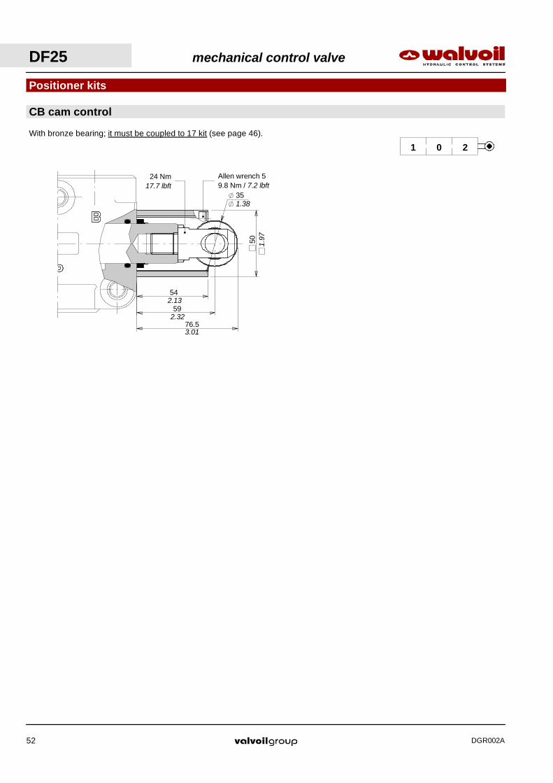
CB cam control
Positioner kits
With bronze bearing; it must be coupled to 17 kit (see page 46).
201
DF25 mechanical control valve
DGR002A52
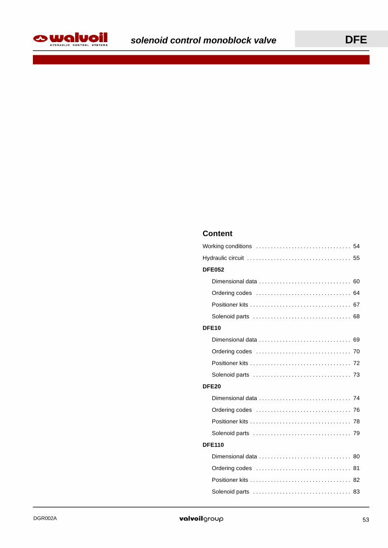
Content
Working conditions 54. . . . . . . . . . . . . . . . . . . . . . . . . . . . . . . .
Hydraulic circuit 55. . . . . . . . . . . . . . . . . . . . . . . . . . . . . . . . . . .
DFE052
Dimensional data 60. . . . . . . . . . . . . . . . . . . . . . . . . . . . . . .
Ordering codes 64. . . . . . . . . . . . . . . . . . . . . . . . . . . . . . . .
Positioner kits 67. . . . . . . . . . . . . . . . . . . . . . . . . . . . . . . . . .
Solenoid parts 68. . . . . . . . . . . . . . . . . . . . . . . . . . . . . . . . .
DFE10
Dimensional data 69. . . . . . . . . . . . . . . . . . . . . . . . . . . . . . .
Ordering codes 70. . . . . . . . . . . . . . . . . . . . . . . . . . . . . . . .
Positioner kits 72. . . . . . . . . . . . . . . . . . . . . . . . . . . . . . . . . .
Solenoid parts 73. . . . . . . . . . . . . . . . . . . . . . . . . . . . . . . . .
DFE20
Dimensional data 74. . . . . . . . . . . . . . . . . . . . . . . . . . . . . . .
Ordering codes 76. . . . . . . . . . . . . . . . . . . . . . . . . . . . . . . .
Positioner kits 78. . . . . . . . . . . . . . . . . . . . . . . . . . . . . . . . . .
Solenoid parts 79. . . . . . . . . . . . . . . . . . . . . . . . . . . . . . . . .
DFE110
Dimensional data 80. . . . . . . . . . . . . . . . . . . . . . . . . . . . . . .
Ordering codes 81. . . . . . . . . . . . . . . . . . . . . . . . . . . . . . . .
Positioner kits 82. . . . . . . . . . . . . . . . . . . . . . . . . . . . . . . . . .
Solenoid parts 83. . . . . . . . . . . . . . . . . . . . . . . . . . . . . . . . .
solenoid control monoblock valve DFE
DGR002A 53

Working conditions
This catalogue shows technical specifications and diagrams measured with mineral oil of 46 mm2/s -- 46 cSt viscosity at 40°C --
104°F temperature.
Standard threads
DFE solenoid control monoblock valve
DGR002A54
DFE052 DFE10 DFE20 DFE110N. of available ways 2--3--6--8 3--6 3--6 12
Nominal flow rating in steady conditions 60 l/min16 US gpmn
90 l/min24 US gpm
140 l/min37 US gpm
90 l/min24 US gpm
Operating pressure (maximum) * without drain 200 bar -- 2900 psip g p ( )with drain 315 bar -- 4600 psi
Available nominal voltage VDC 12--2448--110 12--24--48 12--24 12--24
VAC 50Hz(with C04 connector) 24--110--220 110--220 24--110--220 24--110--220
Nominal power W 38 60 60 60
Internal leakage A(B)→T ∆p=100 bar 1450 psi with fuidand valve at 40°C − 104°F
7 cm3/min0.43 in3/min
10 cm3/min0.61 in3/min
15 cm3/min0.92 in3/min
10 cm3/min0.61 in3/min
Hydraulic fluid Mineral base oil
Fluid temperature with NBR seals from --20°C to 80°C / from --4°F to 176°F
with FPM seals from --20°C to 100°C / from --4°F to 212°F
Viscosity operating range from 15 to 75 mm2/s / from 15 to 75 cSty
minimum 12 mm2/s / 12 cSt
maximum 400 mm2/s / 400 cSt
Max. level of contamination --/19/16 -- ISO 4406 / NAS 1638 -- class10
Ambient temperature forworking conditions from --20°C to 50°C / from --4°F to 122°F
NOTE -- For different working conditions please contact Sales Dept.(*) -- This value is reachable only in steady conditions; for dynamic working conditions see the related pages.
REFERENCE STANDARDS
BSP UN--UNF METRIC
THREADACCORDING TO
ISO 228/1 ISO 263 ISO 262 ISO 262ACCORDING TO BS 2779 ANSI B1.1 unified
CAVITYACCORDING TO
ISO 1179 11926 9974--1 6149ACCORDING TO SAE J1926 J2244
DIN 3852--2shape X or Y
3852--1shape X or Y
PORTS THREAD
ALL PORTS BSP UN--UNF METRIC(ISO 9974--1)
METRIC(ISO 6149)
DFE052 G 3/8 3/4--16 (SAE 8) M18x1,5
DFE10 G 1/2 7/8--14 (SAE 10)
DFE20 G 3/4 1 1/16--12 (SAE 12)
DF110 G 1/2 7/8--14 (SAE 10) M22x1.5 M22x1.5
DRAIN PORT
L G 1/4 9/16--18 (SAE 6)7/16--20 (SAE4)* M12x1.5 M12x1.5
(*) For DFE052/8 and series DFE20 diverter valves Optional threads: for availability contactSales Department

Pressure drop versus flow
P→A
0
5
10
15
20
0 20 40 60 80
Flow
Pre
ssur
e
(bar)
(l/min)
Spool A(B)
200
100
(psi)
5 10 15 (US gpm)20
Available as body only in DFE052/2 execution; for other executions 3--way body is used.
A
P
1 2
A
P
1 2
Spool type A Spool type B
0
100
200
300
400
0 20 40 60
Hydraulic circuit
2--way
Solenoid
Spool
Plug and return spring kit
Diverter valve body
Performance data
Flow
Pre
ssur
e
(bar)
(l/min)
Minimum dynamic conditions
(supply = Vn--10%, coil at 70 °C -- 158 °F)
With drain
Without drain
3000
1500
(psi)
4500
A
P
5 10 15 (US gpm)
solenoid control monoblock valve DFE
DGR002A 55
0
5
10
15
20
0 60 120 180
Portata
Pre
ssio
ne
(bar)
(l/min)
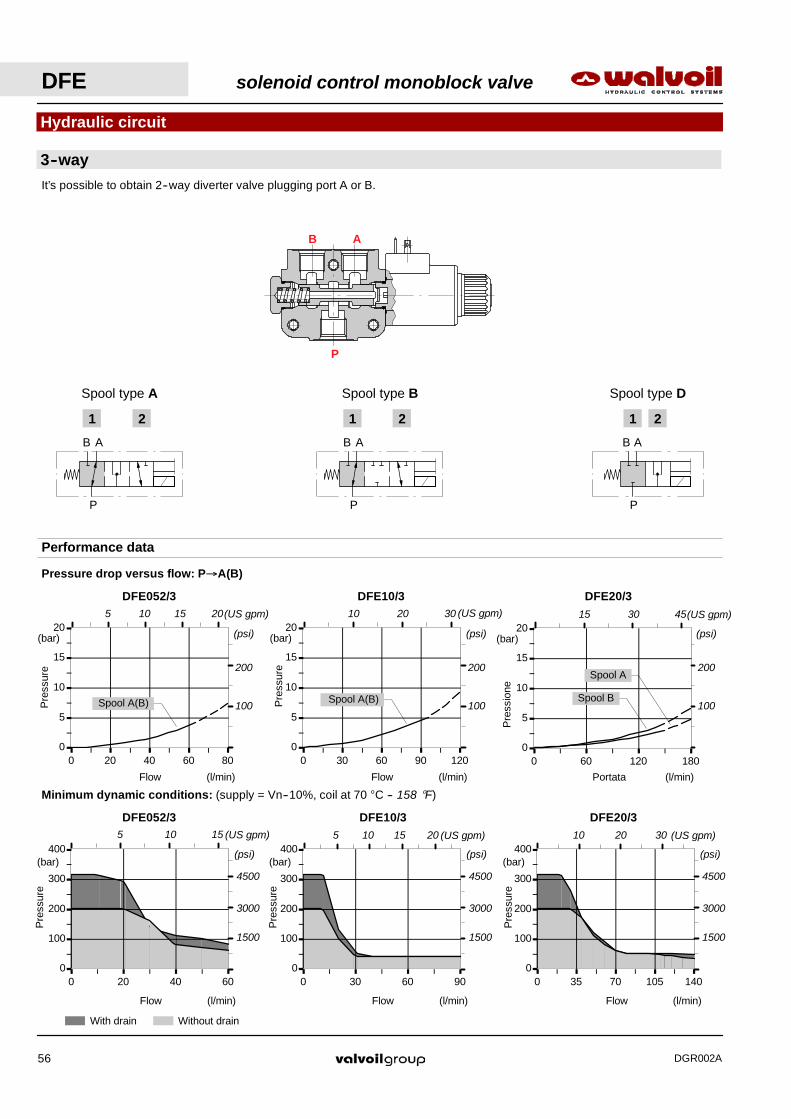
DFE20/3
Spool B
Spool A200
100
(psi)
15 30 45(US gpm)
0
5
10
15
20
0 30 60 90 120
Flow
Pre
ssur
e
(bar)
(l/min)
DFE10/3
Spool A(B)
200
100
(psi)
10 20 30 (US gpm)
0
5
10
15
20
0 20 40 60 80
Flow
Pre
ssur
e
(bar)
(l/min)
DFE052/3
Spool A(B)
200
100
(psi)
5 10 15 (US gpm)20
B
P
1 2
B
P
1 2
A A
Spool type BSpool type A Spool type D
B
P
1 2
A
0
100
200
300
400
0 35 70 105 140
Hydraulic circuit
3--wayIt’s possible to obtain 2--way diverter valve plugging port A or B.
Performance data
Pressure drop versus flow: P→A(B)
Minimum dynamic conditions: (supply = Vn--10%, coil at 70 °C -- 158 °F)
0
100
200
300
400
0 20 40 60
Flow
Pre
ssur
e
(bar)
(l/min)
DFE052/3
0
100
200
300
400
0 30 60 90
Flow
Pre
ssur
e
(bar)
(l/min)
DFE10/3
Flow
Pre
ssur
e
(bar)
(l/min)
DFE20/3
With drain Without drain
3000
1500
(psi)
4500
3000
1500
(psi)
4500
3000
1500
(psi)
4500
B A
P
5 10 15 (US gpm) 5 10 15 (US gpm)20 10 20 30 (US gpm)
DFE solenoid control monoblock valve
DGR002A56

0
5
10
15
20
0 60 120 180
Flow
Pre
ssur
e
(bar)
(l/min)
DFE20/6
Spool B
Spool A200
100
(psi)
15 30 45(US gpm)
0
5
10
15
20
0 40 80 120
Flow
Pre
ssur
e
(bar)
(l/min)
DFE10/6
Spool A(B)
200
100
(psi)
10 20 30 (US gpm)
0
5
10
15
20
0 20 40 60 80
Flow
Pre
ssur
e
(bar)
(l/min)
DFE052/6
Spool A(B)
200
100
(psi)
5 10 15 (US gpm)20
CE
BA
DFCE
1 2
BA
DF CE
1 2
BA
DF
1 2
Spool type A Spool type B Spool type H
DFE20/6
0
100
200
300
400
0 35 70 105 140
Flow
Pre
ssur
e
(bar)
(l/min)
0
100
200
300
400
0 30 60 90
Flow
Pre
ssur
e
(bar)
(l/min)
DFE10/6
0
100
200
300
400
0 20 40 60
Hydraulic circuit
6--way
Performance data
Pressure drop versus flow: A→E(C).
Minimum dynamic conditions: (supply = Vn--10%, coil at 70 °C -- 158 °F)
Flow
Pre
ssur
e
(bar)
(l/min)
DFE052/6
3000
1500
(psi)
4500
3000
1500
(psi)
4500
3000
1500
(psi)
4500
C D
A
E F
B
5 10 15 (US gpm) 5 10 15 (US gpm)20 10 20 30 (US gpm)
With drain Without drain
solenoid control monoblock valve DFE
DGR002A 57

DFE solenoid control monoblock valve
DGR002A58
A E
C H
D
B
F G
0
10
20
30
0 20 40 60 80
Flow
Pre
ssur
e
(bar)
(l/min)
Pressure drop versus flow
A→C
Spool B
Spool A
200
100
(psi)
300
400
5 10 15 (US gpm)20
HYdraulic circuit
8--way
FE
1 2
BA
DC GH
0
FE
BA
DC GH
Spool type A
Spool type B
Performance data
0
100
200
300
400
0 20 40 60
Flow
Pre
ssur
e
(bar)
(l/min)
Minimum dynamic conditions
(supply = Vn--10%, coil at 70 °C -- 158 °F)
With drain Without drain
3000
1500
(psi)
4500
5 10 15 (US gpm)

0
100
200
300
400
0 30 60 90
Flow
Pre
ssur
e
(bar)
(l/min)
Minimum dynamic conditions
(supply = Vn--10%, coil at 70 °C -- 158 °F)
0
5
10
15
20
0 30 60 900
5
10
15
20
0 30 60 90
Hydraulic circuit
12--way
Performance data
Flow
Pre
ssur
e
(bar)
(l/min)
In position 1
A3 B3 C3 D3
A2B2 C2
A1 B1
D2
C1 D1
A2
B2
C2
D2
A3
B3
C3D3
A1
B1
C1
D1
1
2
A1⇒A2 / B1⇒B2
C1⇒C2 / D1⇒D2
Pressure drop versus flow
Flow
Pre
ssur
e
(bar)
(l/min)
In position 2
A1⇒A3 / B1⇒B3
C1⇒C3 / D1⇒D3
With drain
Without drain
Spool type B
200
100
(psi)
200
100
(psi)
3000
1500
(psi)
4500
5 10 15 (US gpm)20 5 10 15 (US gpm)20 5 10 15 (US gpm)20
solenoid control monoblock valve DFE
DGR002A 59
24B
IH
25 38 9 808
9 38
72
==
42=
=
63
160
2.83
1.500.35
2.48
1.65
0.980.32 1.50 0.35 3.15
6.30
1
2
==
4041.5
8.20.33
1.63
1.57
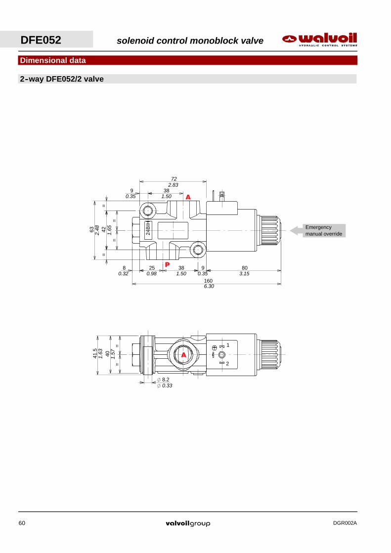
Emergencymanual override
Dimensional data
2--way DFE052/2 valve
P
A
A
DFE052 solenoid control monoblock valve
DGR002A60
1
2
20
4042
16
32
45∅
6.5 n.3 holes
1.65
1.57
0.79
0.63
1.26
0.26
1.77
∅
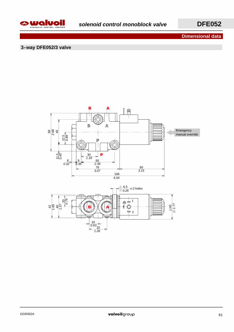
Emergencymanual override
30
6098
78 80
166
22.5
4511
.5
68
2.36
1.18
0.32
3.07 3.15
0.35
0.45
0.89
2.68
Dimensional data
3--way DFE052/3 valve
6.54
P
AB
AB
solenoid control monoblock valve DFE052
DGR002A 61

DFE052 solenoid control monoblock valve
DGR002A62
29.3
92.68
180.6
0.47
5276
1
2
45
80
26
34
46.3
∅
Emergencymanual override
1.82
2.99
2.05
12
1.02
1.15 1.34
0.32 3.65 3.15
7.11
1.77
∅
20
33
55
6.5n.3 holes
2.17
1.30
0.79
0.26
Emergencymanual override
Dimensional data
6--way DFE052/6 valve
FE
DC
BA
FE
BA

10 125 10
36,75 39 39
42.54038
14580
305
1073 9345
∅
10100.394.92
1.45 1.54 1.54
0.39
12.0
5.713.15
1.50 1.57 1.67
1.77
∅
2.87
3.66
0.39
10 0.39
6.5 n.3 holes0.26
1
2
1
2
36.753939
21.5 30
66.5
68.5
Emergencymanual override
1.54 1.54 1.45
0.85 1.
18
2.62 2.70
Emergencymanual override
Dimensional data
8--way DFE52/8 valve
C
A
GF
H B
E D
C
GF
H B
solenoid control monoblock valve DFE052
DGR002A 63
DFE052 solenoid control monoblock valve
DGR002A64
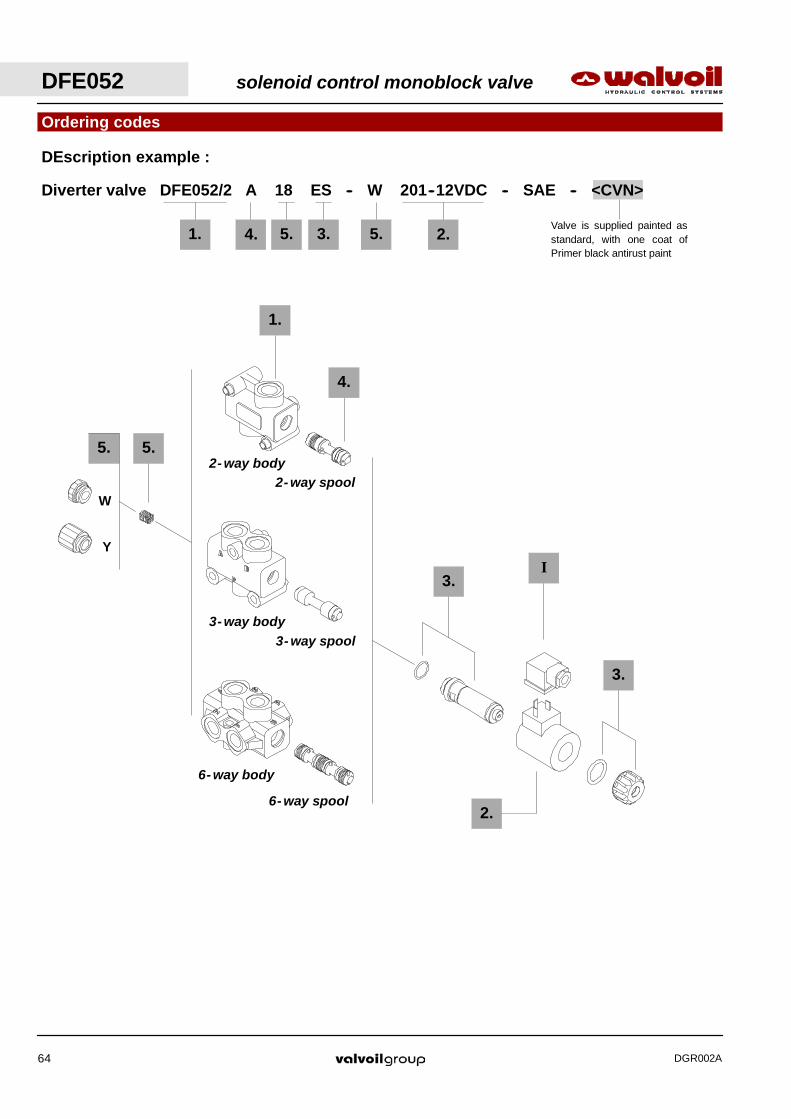
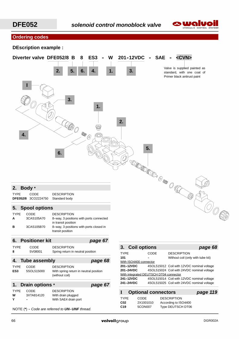
Valve is supplied painted asstandard, with one coat ofPrimer black antirust paint
Ordering codes
Diverter valve DFE052/2 A 18 ES -- W 201--12VDC -- SAE -- <CVN>
DEscription example :
5.
1.
4.
W
1. 4. 5. 3. 2.5.
2.
Y
5.
I
3- way body3- way spool
6- way body
6- way spool
2- way body2- way spool
3.
3.

solenoid control monoblock valve DFE052
DGR002A 65
NOTE (*) -- Codes are referred to UN- UNF thread.
4. Spool optionsTYPE CODE DESCRIPTIONA 3CAS105645 6--way, 2 positions with ports connected
in transit positionB 3CAS105746 6--way, 2 positions with ports closed in
transit positionH 3CAS105845 6--way, 2 positions, D↔C in position 1,
F↔E in position 2, ports closed intransit position
1. Body *TYPE CODE DESCRIPTIONDFE052/6 3CO2222725 Standard body
6- way
1. Body *TYPE CODE DESCRIPTIONDFE052/3 3CO2221725 Standard body
4. Spool optionsTYPE CODE DESCRIPTIONA 3CAS105345 3--way, 2 positions with ports connected
in transit positionB 3CAS105445 3--way, 2 positions with ports closed in
transit positionD 3CAS105546 3--way, 2 positions, without transit
position, with ports closed in rest position
3- way
1. Body *TYPE CODE DESCRIPTIONDFE052/2 3CO2220721 Standard body
4. Spool optionsTYPE CODE DESCRIPTIONA 3CAS105245 2 positions with open centre in neutralB 3CAS105145 2 positions with closed centre in neutral
2- way
Ordering codes
TYPE CODE DESCRIPTIONC02 2X1001010 According to ISO4400C19 5CON007 Type DEUTSCH DT06
I Optional connectors page 119
5. Positioner kits page 67YPE CODE DESCRIPTION18...W 5TAP001 Spring return in position 1
18...Y 5GIU003 * Spring return in position 1, with SAE6drain port
3. Tube assembly page 68TTYPE CODE DESCRIPTIONES 5SOL515000 Spring return in position 1 (without coil)
2. Coil options page 68TYPE CODE DESCRIPTION101 -- Without coil (only with tube kit)With ISO4400 connector201--12VDC 4SOL515012 Coil with 12VDC nominal voltage201--24VDC 4SOL515024 Coil with 24VDC nominal voltageWith integrated DEUTSCH DT04 connector241--12VDC 4SOL515014 Coil with 12VDC nominal voltage241--24VDC 4SOL515025 Coil with 24VDC nominal voltage
DFE052 solenoid control monoblock valve
DGR002A66
Valve is supplied painted asstandard, with one coat ofPrimer black antirust paint
Ordering codes
Diverter valve DFE052/8 B 8 ES3 -- W 201--12VDC -- SAE -- <CVN>
DEscription example :
4.
2.
2. 5. 6. 4. 1. 3.
6.
3.1.
I
5.
1. Drain options * page 67TYPE CODE DESCRIPTIONW 3XTA814120 With drain pluggedY -- With SAE4 drain port
2. Body *TYPE CODE DESCRIPTIONDFE052/8 3CO2224750 Standard body
5. Spool optionsTYPE CODE DESCRIPTIONA 3CAS105A70 8--way, 3 positions with ports connected
in transit positionB 3CAS105B70 8--way, 3 positions with ports closed in
transit position
6. Positioner kit page 67TYPE CODE DESCRIPTION8 5V08001 Spring return in neutral position
4. Tube assembly page 68TYPE CODE DESCRIPTIONES3 5SOL515000 With spring return in neutral position
(without coil)
TYPE CODE DESCRIPTIONC02 2X1001010 According to ISO4400C19 5CON007 Type DEUTSCH DT06
I Optional connectors page 119
3. Coil options page 68TYPE CODE DESCRIPTION101 -- Without coil (only with tube kit)With ISO4400 connector201--12VDC 4SOL515012 Coil with 12VDC nominal voltage201--24VDC 4SOL515024 Coil with 24VDC nominal voltageWith integrated DEUTSCH DT04 connector241--12VDC 4SOL515014 Coil with 12VDC nominal voltage241--24VDC 4SOL515025 Coil with 24VDC nominal voltage
NOTE (*) -- Code are referred to UN- UNF thread.
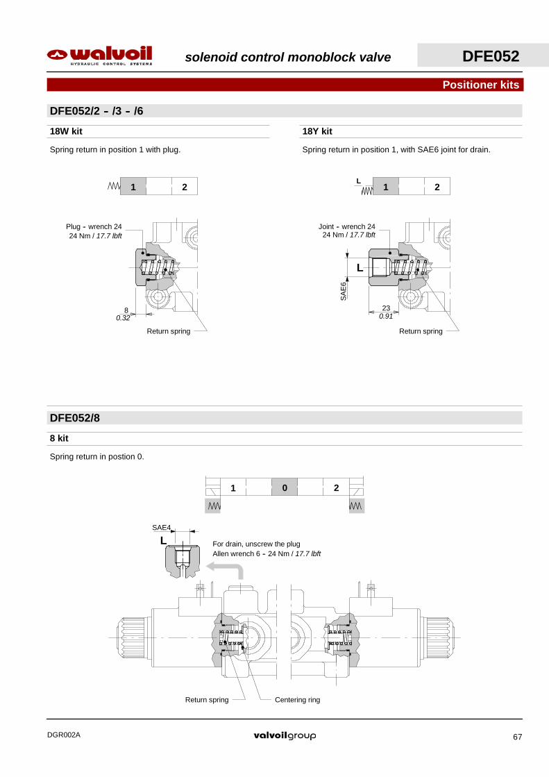
LSAE4
L
SA
E6
23
Joint -- wrench 2424 Nm / 17.7 lbft
Return spring
0.91
8 kit
Spring return in postion 0.
Return spring Centering ring
For drain, unscrew the plugAllen wrench 6 -- 24 Nm / 17.7 lbft
18W kit 18Y kit
Spring return in position 1 with plug. Spring return in position 1, with SAE6 joint for drain.
8
Plug -- wrench 2424 Nm / 17.7 lbft
Return spring
0.32
DFE052/2 -- /3 -- /6
Positioner kits
DFE052/8
01 2
1 2 1 2L
solenoid control monoblock valve DFE052
DGR002A 67

M20
x1
87.3
23
3.44
0.91
Manual tightening;max. torque 6.6 Nm / 4.9 lbft
Wrench 2020 Nm / 14.7 lbft
54
452353.7
2.11
0.91
2.13
1.77Operating featuresPlunger stroke : 7.1 mm / 0.28 in. . . . . . . . . . . . .
Coil options
ES tube assembly
Solenoid parts
Thermoplasticprotective covering
Needs C02 connector,see page 119.
With ISO4400 connector(weather protection IP65)
With integrated DEUTSCH 04 connector(weather protection IP67)
Needs C19 connector,see page 119.
Operating featuresNominal voltage : 12VDC / 24VDC. . . . . . . . . . .Nominal voltage tolerance : ±10%. . .Power rating : 38 W. . . . . . . . . . . . . .Duty cycle : 100%. . . . . . . . . . . . . . . .Weather protection : Depending on connector type. . . . . . . . .Coil insulation : Class H. . . . . . . . . . . . .
Push for manualoverride
DFE052 solenoid control monoblock valve
DGR002A68

solenoid control monoblock valve DFE10
DGR002A 69
2
1
34.7 437 121
240.4
32.5
6511
.75
88.5 64 2.52
4.76
9.46
1.37 1.690.28
1.28
3.48
2.56
0.46
62
40
23
56.2
112.4
8.3N 3 holes
4.43
2.21
2.44
1.57
0.91
0.33
25
5074
12
32.5
65
10.27 121
213.5
1
2
Emergencymanual override2.
91
1.97
0.47
0.98
1.280.28 0.40
8.41
4.76
2.56
22.5
4546.5
18
36 8.3 n.3 holes
64
85.43.36
2.52
0.71
1.42 0.33
1.83
1.77
0.89
Emergencymanual override
Dimensional data
3--way DFE10/3 valve
6--way DFE10/6 valve
P
AB
AB
FE
BA
FE
DC
BA

DFE10 solenoid control monoblock valve
DGR002A70
Valve is supplied painted asstandard, with one coat ofPrimer black antirust paint
Ordering codes
Diverter valve DFE10/3 A 18 ES -- W 202--12VDC -- SAE -- <CVN>
Description example :
1. 4. 5. 3. 2.5.
5.1.
4.W
2.
Y
5.
I
3.
3.
II
3- way body
3- way spool
6- way body
6- way spool

solenoid control monoblock valve DFE10
DGR002A 71
TYPE CODE DESCRIPTION
SAE10 3XTAP826160* Body conversion from 3--way to 2--waycircuit
II Ports plug
4. Spool optionsTYPE CODE DESCRIPTIONA 3CAS110641 6--way, 2 positions with ports connected
in transit positionB 3CAS110741 6--way, 2 positions with ports closed in
transit positionH 3CAS110840 6--way, 2 positions, D↔C in position 1,
F↔E in position 2, ports closed intransit position
N 3CAS110952 6--way, 2 positions with ports closed intransit position, with check valve
6- way
1. Body *TYPE CODE DESCRIPTIONDFE10/6 3CO2242721 Standard body
1. Body *TYPE CODE DESCRIPTIONDFE10/3 3CO2241720 Standard body
4. Spool optionsTYPE CODE DESCRIPTIONA 3CAS110341 3--way, 2 positions with ports connected
in transit positionB 3CAS110441 3--way, 2 positions with ports closed in
transit positionD 3CAS110540 3--way, 2 positions, without transit
position, with ports closed in rest position
3- way
Ordering codes
NOTE (*) -- Codes are referred to UN- UNF thread.
TYPE CODE DESCRIPTIONC02 2X1001010 According ISO4400C04 2X1001040 According to ISO4400 with rectifierC19 5CON007 Type DEUTSCH DT06
I Optional connectors page 119
5. Positioner kits page 72TYPE CODE DESCRIPTION18...W 5TAP002 Spring return in position 1
18...Y 5GIU005 * Spring return in position 1, with SAE6drain port
3. Tube assembly page 73TYPE CODE DESCRIPTIONES 5SOL516000 Spring return in position 1 (without coil)
2. Coil options page 73TYPE CODE DESCRIPTION102 -- Without coil (only with tube kit)With ISO4400 connector202--12VDC 4SOL516012 Coil with 12VDC nominal voltage202--24VDC 4SOL516024 Coil with 24VDC nominal voltage202--48VDC 4SOL516048 Coil with 48VDC nominal voltage202--92VDC 4SOL516094 Coil with 92VDC nominal voltage
(for 110VAC): need C04 connector202--192VDC 4SOL516192 Coil with 192VDC nominal voltage
(for 220VAC): need C04 connectorWith flying leads and DEUTSCH DT04 connector241--12VDC 4SOL516412 Coil with 12VDC nominal voltage241--24VDC 4SOL516424 Coil with 24VDC nominal voltage
23
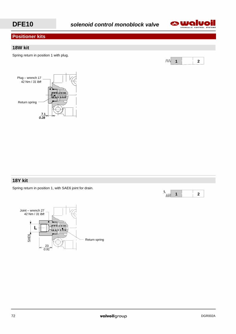
Return springSA
E6
L
0.91
Joint -- wrench 2742 Nm / 31 lbft
Spring return in position 1 with plug.
Plug -- wrench 1742 Nm / 31 lbft
Return spring
7.10.28
Spring return in position 1, with SAE6 joint for drain.
Plug -- wrench 1742 Nm / 31 lbft
Return spring
7.10.28
Positioner kits
1 2
1 2L
18W kit
18Y kit
DFE10 solenoid control monoblock valve
DGR002A72

115
129.5
25.5
M22
x1.5
Manual tightening;max. torque 6.6 Nm / 4.9 lbft
Wrench 1324 Nm / 17.7 lbft
1.00
4.53
5.10
65
25.5 6276
78
2.44
1.00
3.07
2.99
2.56
Operating featuresPlunger stroke : 10.2 mm / 0.40 in. . . . . . . . . . . . .
Solenoid parts
ES tube assembly
Coil options
With ISO4400 connector(weather protection IP65)
Needs C02 connector,see page 119.
Thermoplasticprotective covering
With flying leads and DEUTSCH DT04 connector(weather protection IP67)
100
Needs C19 connector,see page 119.
Push for manualoverride
3.94
Operating featuresNominal voltage : 12--24--48--92--192VDC. . . . . . . . . . .Nominal voltage tolerance : ±10%. . .Power rating : 60 W. . . . . . . . . . . . . .Duty cycle : 100%. . . . . . . . . . . . . . . .Weather protection : depending on connector type. . . . . . . . .Coil insulation : Class H. . . . . . . . . . . . .
solenoid control monoblock valve DFE10
DGR002A 73

DFE20 solenoid control monoblock valve
DGR002A74
26
52
27.5
555765
10.2n.3 holes
2.56
2.24
2.17
1.08
2.05
1.02
0.41
42.5
8512.59
110 107
226
Emergencymanual override
3.350.490.35
1.67
4.33 4.21
8.90
30
6085
12.5
3.35
2.36
1.18
0.49
Dimensional data
3--way DFE20/3 valve
P
AB
AB
solenoid control monoblock valve DFE20
DGR002A 75
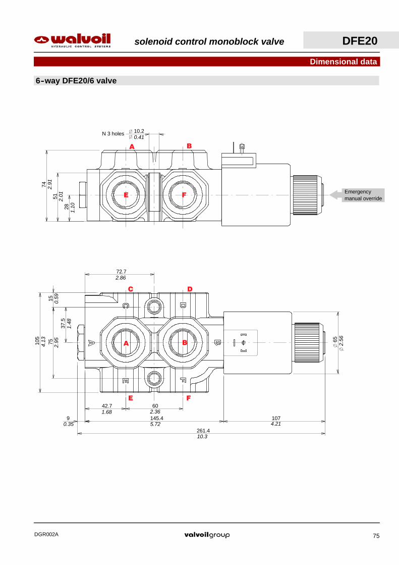
42.7 60
145.49 107
261.4
37.5
7515
105 65
72.72.86
0.59
4.13
2.95
1.48
4.215.720.35
1.68 2.36
10.3
2.56
74
51
28
10.2N 3 holes
1.10
2.01
2.91
0.41
Emergencymanual override
Dimensional data
6--way DFE20/6 valve
FE
BA
FE
DC
BA

DFE20 solenoid control monoblock valve
DGR002A76
Valve is supplied painted asstandard, with one coat ofPrimer black antirust paint
Ordering codes
Diverter valve DFE20/3 A 18 ES -- W 201--12VDC -- SAE -- <CVN>
Description example :
1. 4. 5. 3. 2.5.
5.
1.
4.
W
Y
5.
I
3.
2.
3.
3- way body
3- way spool
6- way body
6- way spool
II

solenoid control monoblock valve DFE20
DGR002A 77
4. Spool optionsTYPE CODE DESCRIPTIONA 3CAS120641 6--way, 2 positions with ports connected
in transit positionB 3CAS120741 6--way, 2 positions with ports closed in
transit positionH 3CAS120841 6--way, 2 positions, D↔C in position 1,
F↔E in position 2, ports closed intransit position
1. Body *TYPE CODE DESCRIPTIONDFE20/6 3CO2263720 Standard body
6- way
1. Body *TYPE CODE DESCRIPTIONDFE20/3 3CO2261720 Standard body
3- way
4. Spool optionsTYPE CODE DESCRIPTIONA 3CAS120341 3--way, 2 positions with ports connected
in transit positionB 3CAS120441 3--way, 2 positions with ports closed in
transit position
Ordering codes
TYPE CODE DESCRIPTIONC02 2X1001010 According ISO4400C04 2X1001040 According to ISO4400 with rectifierC19 5CON007 Type DEUTSCH DT06
I Optional connectors page 119
5. Positioner kits page 78TYPE CODE DESCRIPTION18...W 5TAP003 Spring return in position 1
18...Y 5GIU008 * Spring return in position 1, with SAE4drain port
3. Tube assembly page 78TYPE CODE DESCRIPTIONES 5SOL519001 Spring return in position 1 (without coil)
2. Coil options page 79TYPE CODE DESCRIPTION101 Without coil (only with tube kit)With ISO4400 connector201--12VDC 4SOL519112 Coil with 12VDC nominal voltage201--24VDC 4SOL519124 Coil with 24VDC nominal voltage201--20VDC 4SOL519120 Coil with 20VDC nominal voltage
(for 24VAC): need C04 connector201--94VDC 4SOL519094 Coil with 94VDC nominal voltage
(for 110VAC): need C04 connector201--192VDC 4SOL519192 Coil with 192VDC nominal voltage
(for 220VAC): need C04 connectorWith flying leads and DEUTSCH DT04 connector241--12VDC 4SOL519412 Coil with 12VDC nominal voltage241--24VDC 4SOL519424 Coil with 24VDC nominal voltage
NOTE (*) -- Codes are referred to UN- UNF thread.
TYPE CODE DESCRIPTION
SAE12 3XTAP832200* Body conversion from 3--way to 2--waycircuit
II Ports plug
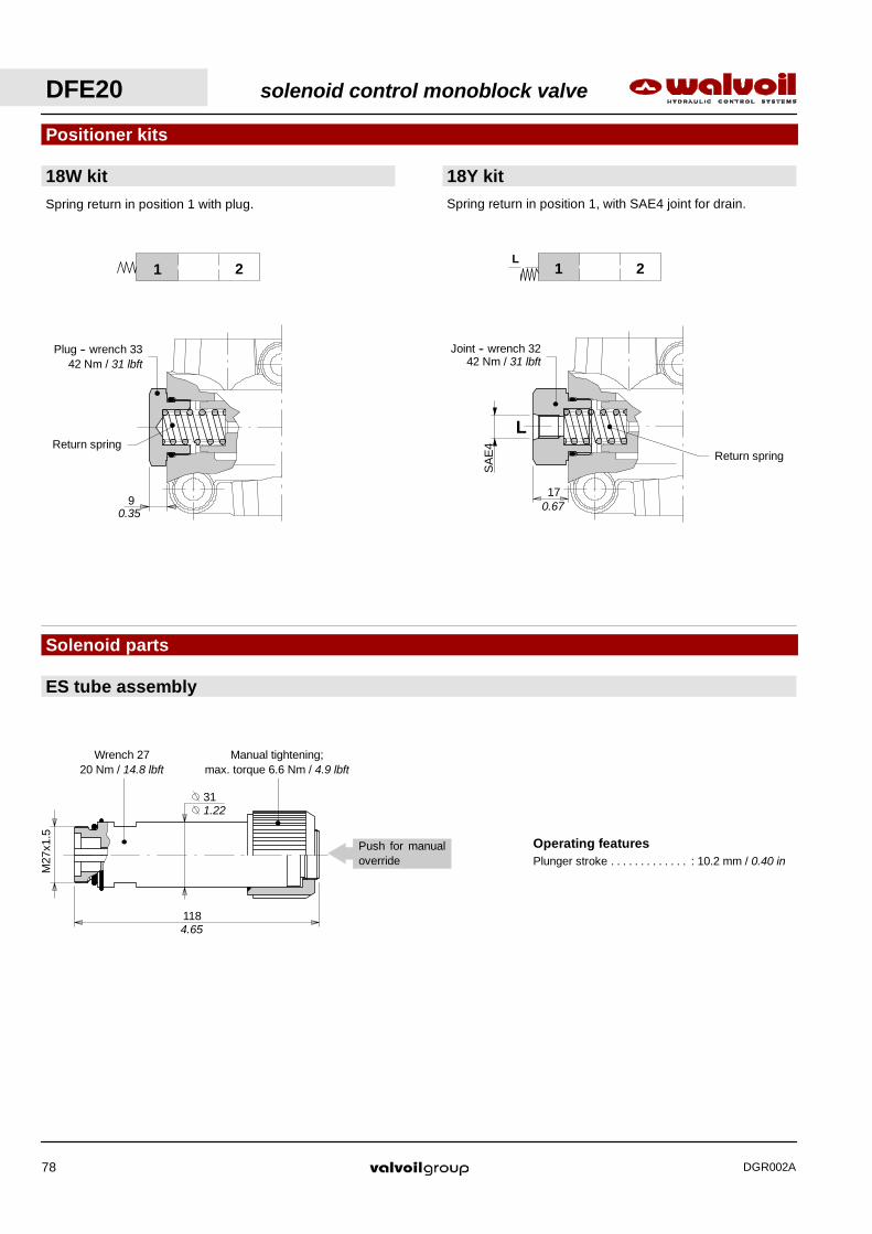
Manual tightening;max. torque 6.6 Nm / 4.9 lbft
Wrench 2720 Nm / 14.8 lbft
M27
x1.5
31
1184.65
1.22
Return spring
17
Joint -- wrench 3242 Nm / 31 lbft
SA
E4
L
0.67
Operating featuresPlunger stroke : 10.2 mm / 0.40 in. . . . . . . . . . . . .
Push for manualoverride
Spring return in position 1 with plug.
9
Plug -- wrench 3342 Nm / 31 lbft
Return spring
0.35
Positioner kits
1 2 1 2L
Solenoid parts
ES tube assembly
18W kit 18Y kitSpring return in position 1, with SAE4 joint for drain.
DFE20 solenoid control monoblock valve
DGR002A78

3176
65
72.3
2.99
2.56
1.22
2.84
Solenoid parts
Coil options
Needs C02 connector,see page 119.
With ISO4400 connector(weather protection IP65)
With flying leads and DEUTSCH DT04 connector(weather protection IP67)
100Thermoplasticprotective covering
Needs C19 connector,see page. 119.
Operating featuresNominal voltage : 12--20--24--94--192VDC. . . . . . . . . . .Nominal voltage tolerance : ±10%. . .Power rating : 60 W. . . . . . . . . . . . . .Duty cycle : 100%. . . . . . . . . . . . . . . .Weather protection : depending on connector type. . . . . . . . .Coil insulation : Class H. . . . . . . . . . . . .
solenoid control monoblock valve DFE20
DGR002A 79

Dimensional data
11 180
27
55
33.537 37 37
318
45.537
91.5
180.1
80.1
130.1
30.1
12 M8
25
70
40
1.46 1.46 1.46 1.32
( n°12 ports)
A2 B2 C2 D2
D1C1B1A1
D3C3B3A3
37 37
7.09
5.12
3.15
1.19
0.47
0.98
2.76
2.17
1.06
7.090.43
3.60
1.57
1.46 1.46 1.46 1.79
12.52
Emergencymanual override
DFE110 solenoid control monoblock valve
DGR002A80

solenoid control monoblock valve DFE110
DGR002A 81
Valve is supplied painted asstandard, with one coat ofPrimer black antirust paint
TYPE CODE DESCRIPTIONC02 2X1001010 According ISO4400C04 2X1001040 According to ISO4400 with rectifierC19 5CON007 Type DEUTSCH DT06
Diverter valve DFE110/12 B 18 ES -- W 201--12VDC -- SAE -- <CVN>
38.Ordering codes
Description example :
1. 2. 3. 4. 5.3.
I
1.
5.
I3.
I Optional connectors page 119
1. Body *TYPE CODE DESCRIPTION110/12 3CO2243720 12--way standard body
3. Positioner kits page 82TYPE CODE DESCRIPTION18...W 5TAP005 Spring return in position 1
18...Y 5GIU011* Spring return in position 1, with SAE6drain port
4. Tube assembly page 82TYPE CODE DESCRIPTIONES 5SOL519001 Spring return in position 1 (without coil)
5. Coil options page 83TYPE CODE DESCRIPTION101 Without coil (only with tube kit)With ISO4400 connector201--12VDC 4SOL519112 Coil with 12VDC nominal voltage201--24VDC 4SOL519124 Coil with 24VDC nominal voltage201--20VDC 4SOL519120 Coil with 20VDC nominal voltage
(for 24VAC): need C04 connector201--94VDC 4SOL519094 Coil with 94VDC nominal voltage
(for 110VAC): need C04 connector201--192VDC 4SOL519192 Coil with 192VDC nominal voltage
(for 220VAC): need C04 connectorWith flying leads and DEUTSCH DT04 connector241--12VDC 4SOL519412 Coil with 12VDC nominal voltage241--24VDC 4SOL519424 Coil with 24VDC nominal voltage
2. Spool optionsTYPE CODE DESCRIPTIONB 3CAS108H40 2 positions with ports closed in transit
position
4.
2.
NOTE (*) -- Codes are referred to UN- UNF thread.

Manual tightening;max. torque 6.6 Nm / 4.9 lbft
Wrench 2720 Nm / 14.8 lbft
M27
x1.5
31
1184.65
1.22
Operating featuresPlunger stroke : 10.2 mm / 0.40 in. . . . . . . . . . . . .
18Y kitSpring return in position 1, with SAE6 joint for drain.Spring return in position 1 with plug.
18W kit
Positioner kits
1 2 1 2L
Solenoid parts
ES tube assembly
Plug -- wrench 3242 Nm / 31 lbft
8.8
REturn spring
0.35
Push for manualoverride
23S
AE
6
L
Joint -- wrench 3342 Nm / 31 lbft
Return spring
0.91
DFE110 solenoid control monoblock valve
DGR002A82
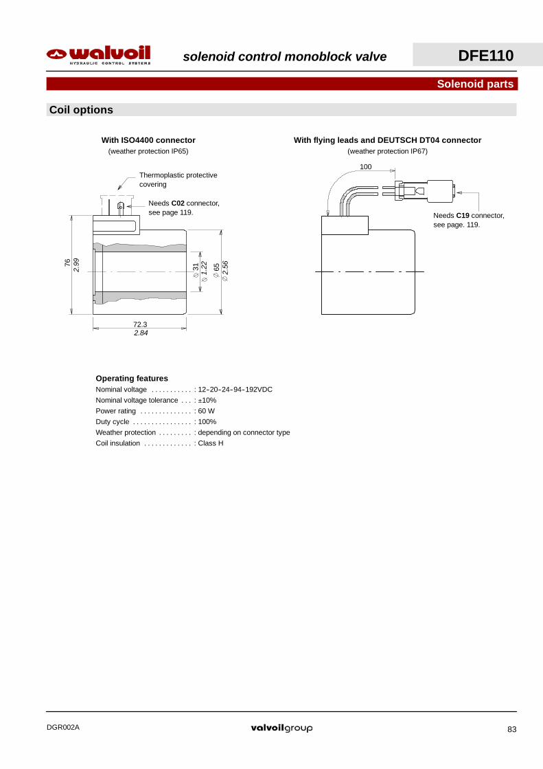
With flying leads and DEUTSCH DT04 connector(weather protection IP67)
100
Needs C19 connector,see page. 119.
3176
65
72.3
2.99
2.56
1.22
2.84
Needs C02 connector,see page 119.
With ISO4400 connector(weather protection IP65)
Thermoplastic protectivecovering
Solenoid parts
Coil options
Operating featuresNominal voltage : 12--20--24--94--192VDC. . . . . . . . . . .Nominal voltage tolerance : ±10%. . .Power rating : 60 W. . . . . . . . . . . . . .Duty cycle : 100%. . . . . . . . . . . . . . . .Weather protection : depending on connector type. . . . . . . . .Coil insulation : Class H. . . . . . . . . . . . .
solenoid control monoblock valve DFE110
DGR002A 83

DFE110 solenoid control monoblock valve
DGR002A84
solenoid control sectional valve DFE
DGR002A 85
Content
Working condition 86. . . . . . . . . . . . . . . . . . . . . . . . . . . . . . . . .
Hydraulic circuit 87. . . . . . . . . . . . . . . . . . . . . . . . . . . . . . . . . . .
DFE080
Dimensional data 89. . . . . . . . . . . . . . . . . . . . . . . . . . . . . . .
Ordering codes 90. . . . . . . . . . . . . . . . . . . . . . . . . . . . . . . .
Positioner kits 92. . . . . . . . . . . . . . . . . . . . . . . . . . . . . . . . . .
Solenoid parts 92. . . . . . . . . . . . . . . . . . . . . . . . . . . . . . . . .
DFE100
Dimensional data 93. . . . . . . . . . . . . . . . . . . . . . . . . . . . . . .
Ordering codes 94. . . . . . . . . . . . . . . . . . . . . . . . . . . . . . . .
Positioner kits 96. . . . . . . . . . . . . . . . . . . . . . . . . . . . . . . . . .
Solenoid parts 96. . . . . . . . . . . . . . . . . . . . . . . . . . . . . . . . .
DFE140
Dimensional data 97. . . . . . . . . . . . . . . . . . . . . . . . . . . . . . .
Ordering codes 98. . . . . . . . . . . . . . . . . . . . . . . . . . . . . . . .
Positioner kits 100. . . . . . . . . . . . . . . . . . . . . . . . . . . . . . . . .
Solenoid parts 100. . . . . . . . . . . . . . . . . . . . . . . . . . . . . . . .
Valvole antiurto 102. . . . . . . . . . . . . . . . . . . . . . . . . . . . . . . .

Working conditions
This catalogue shows technical specifications and diagrams measured with mineral oil of 46 mm2/s -- 46 cSt viscosity at 40°C --
104°F temperature.
Standard threads
DFE solenoid control sectional valve
DGR002A86
DFE080 DFE100 DFE140N. of available ways 6--8--10 6--8--10 6--8--10
Nominal flow rating in steady conditions 25 l/min6.6 US gpm
50 l/min13 US gpm
80 l/min21 US gpm
Operating pressure (maximum) * without drain 200 bar -- 2900 psip g p ( )with drain 315 bar -- 4600 psi
Available nominal voltage VDC 12--24 12--24 12--24g
VAC 50Hz(with C04 connector) 24--110--220 24--110--220 24--110--220
Nominal power W 38 60 60
Internal leakage A(B)→T ∆p=100 bar 1450 psi with fuidand valve at 40°C − 104°F
7 cm3/min0.43 in3/min
10 cm3/min0.61 in3/min
10 cm3/min0.61 in3/min
Tie rods tightening torque 9.8 Nm7.2 lbft
18 Nm13.3 lbft
25 Nm18.4 lbft
Hydraulic fluid Mineral base oil
Fluid temperature with NBR seals from --20°C to 80°C / from --4°F to 176°F
with FPM seals from --20°C to 100°C / from --4°F to 212°F
Viscosity operating range from 15 to 75 mm2/s / from 15 to 75 cSty
minimum 12 mm2/s / 12 cSt
maximum 400 mm2/s / 400 cSt
Max. level of contamination --/19/16 -- ISO 4406 / NAS 1638 -- class10
Ambient temperature forworking conditions from --20°C to 50°C / from --4°F to 122°F
NOTE -- For different working conditions please contact Sales Dept.(*) -- This value is reachable only in steady conditions; for dynamic working conditions see the related pages.
REFERENCE STANDARDS
BSP UN--UNF METRIC
THREADACCORDING TO
ISO 228/1 ISO 263 ISO 262 ISO 262ACCORDING TO BS 2779 ANSI B1.1 unified
CAVITYACCORDING TO
ISO 1179 11926 9974--1 6149ACCORDING TO SAE J1926 J2244
DIN 3852--2shape X or Y
3852--1shape X or Y
PORTS THREAD
ALL PORTS BSP UN--UNF METRIC(ISO 9974--1)
METRIC(ISO 6149)
DFE080 G 1/4 7/16--20 (SAE 4)
DFE100 G 3/8 3/4--16 (SAE 8) M18x1.5 M18x1.5
DFE140 G 1/2 7/8--14 (SAE 10)
DRAIN PORT
L G 1/4 7/16--20 (SAE 4)*9/16--18 (SAE 6) M12x1.5 M12x1.5
(*) For DFE080 diverter valve Optional threads: for availability contactSales Department

solenoid control sectional valve DFE
DGR002A 87
0
10
20
30
40
50
0 5 10 15 20 250
2
4
6
8
10
0 20 40 60 80
Hydraulic circuit
A1
C1
A2
C2L
B1B2
Performace data
A1
C1
A2
C2L C1’ C2’L
B1B2
A1
C1
A2
C2L C1” C2”L
B1B2
C1’ C2’L
6--way 8--way 10--way
0
2
4
6
8
10
0 10 20 30 40 50
A1⇒B1 / A1⇒C1
A1⇒B1’ / A1⇒C1’A1⇒B1” / A1⇒C1”
DFE100
Pre
ssur
e
Flow (l/min)
(bar)
DFE080
Pre
ssur
e
Flow (l/min)
(bar)
Pressure drop versus flow
Flow
Pre
ssur
e
(l/min)
(bar)
DFE140
Minimum dynamic conditions: (supply = Vn--10%, coil at 70 °C -- 158 °F)
0
100
200
300
400
0 20 40 60 80
Flow
Pre
ssur
e
(l/min)
(bar)
DFE140
0
100
200
300
400
0 5 10 15 20 25
Pre
ssur
e
Flow (l/min)
(bar)
DFE080
0
100
200
300
400
0 10 20 30 40 50
Pre
ssur
e
Flow (l/min)
(bar)
DFE100
With drain Without drain
400
200
(psi)600
80
40
(psi)120
80
40
(psi)120
3000
1500
(psi)
4500
3000
1500
(psi)
4500
3000
1500
(psi)
4500
2 4 6 (US gpm) 4 8 12 (US gpm) 5 10 15 (US gpm)20
2 4 6 (US gpm) 4 8 12 (US gpm) 5 10 15 (US gpm)20
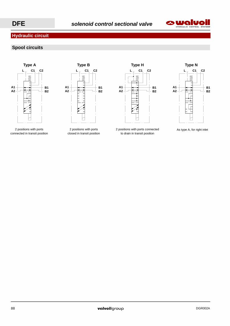
DFE solenoid control sectional valve
DGR002A88
Hydraulic circuit
A1
C1
A2
C2L
B1B2
A1
C1
A2
C2L
B1B2
A1
C1
A2
C2L
B1B2
Spool circuits
A1
C1
A2
C2L
B1B2
Type A Type B Type H Type N
2 positions with portsconnected in transit position
2 positions with portsclosed in transit position
2 positions with ports connectedto drain in transit position
As type A, for right inlet

Dimensional data
The drawing below show diverter valve in 10--way configuration.
20.3
21.3
7054
.325
.5
158.
221.4 44 44 22.6
5.45.45.4
F
25.4 49.4 49.4
E
827
.721
24.8
6
47
23
54
10.5
4712
.5
7 35.4 14 35.4 14 35.4 7
nr.6 holes M6
B1
B2
C1”
C2”
C1’
C2’
C1
C2
A1
A2
A1
A2
28.3
21
B1
B2
D
D
Section D--D
1.11
0.83
6.23
2.14
1.00
0.80
0.84
1.00 1.94 1.94
0.84 1.73 1.73 0.89
0.21 0.21 0.21 1.85
0.98
1.09
0.83
0.31
0.24
0.91
2.13
0.41
1.85
0.49
0.28 1.39 0.55 1.39 1.390.55 0.28
thread depth = 9 mm / 0.35 in
Emergencymanual override
2.76
solenoid control sectional valve DFE080
DGR002A 89
TYPEE F Weight
TYPEmm in mm in kg lb
DFE080/6 49.4 1.94 49.4 1.94 1.4 3.1
DFE080/8 105 4.13 98.8 3.86 2.8 6.2
DFE080/10 155 6.10 148.2 5.84 4.3 9.5

DFE080 solenoid control sectional valve
DGR002A90
Valve body is suppliedgalvanized
Diverter valve DFE080/10 A 18 ES -- W 201--12VDC -- SAE -- CRZ
Ordering codes44.
Description example :
1. 2. 3. 4. 5.3.
I
1.
4.
3.
2.
5.
I
6.
6.

Ordering codes
NOTE (*) -- Codes are referred to UN- UNF thread.
TYPE CODE DESCRIPTIONC02 2X1001010 According to ISO4400C19 5CON007 Type DEUTSCH DT06
I Optional connectors page 119
1. Body *TYPE CODE DESCRIPTION080/6 3CO2208720 6--way body080/8 “ Nr 2 of 6--way body for 8--way circuit080/10 “ Nr 3 of 6--way body for 10--way circuit
3. Positioner kits page 92TYPE CODE DESCRIPTION18...W 5TAP007 Spring return in position 1
18...Y 5GIU015 * Spring return in position 1, with SAE4drain port
4. Tube assembly page 92TYPE CODE DESCRIPTIONES 5SOL515000 Spring return in position 1 (without coil)
5. Coil options page 92TYPE CODE DESCRIPTION101 -- Without coil (only with tube kit)With ISO4400 connector201--12VDC 4SOL515012 Coil with 12VDC nominal voltage201--24VDC 4SOL515024 Coil with 24VDC nominal voltageWith integrated DEUTSCH DT04 connector241--12VDC 4SOL515014 Coil with 12VDC nominal voltage241--24VDC 4SOL515025 Coil with 24VDC nominal voltage
2. Spool optionsTYPE CODE DESCRIPTIONA 3CAS108640 2 positions with ports connected in transit
positionB 3CAS108740 2 positions with ports closed in transit
positionH 3CAS108840 2 positions with ports connected to drain
in transit positionN 3CAS108940 As type A, for right inlet
6. Tie rods kit and O--ring sealsCODE MOUNTED ON5TIR080008 DFE080/8 diverter valve5TIR080010 DFE080/10 diverter valve
solenoid control sectional valve DFE080
DGR002A 91

M20
x1
87.3
23
3.44
0.91
Manual tightening;max. torque 6.6 Nm / 4.9 lbft
Wrench 2020 Nm / 14.7 lbft
54
452353.7
2.11
0.91
2.13
1.77
Operating featuresPlunger stroke : 7.1 mm / 0.28 in. . . . . . . . . . . . .
Spring return in position 1 with plug.
18W kit 18Y kitSpring return in position 1, with SAE4 joint for drain.
Positioner kits
1 2 1 2L
Solenoid parts
ES tube assemply
23S
AE
4
L
Return spring
Plug -- wrench 2442 Nm / 31 lbft
Return spring8
Coil options
With ISO4400 connector(weather protection IP65)
With integrated DEUTSCH 04 connector(weather protection IP67)
Needs C19 connector,see page 119.
Needs C02 connector,see page 119.
Thermoplasticprotective covering
0.31 0.91
Operating featuresNominal voltage : 12VDC / 24VDC. . . . . . . . . . .Nominal voltage tolerance : ±10%. . .Power rating : 38 W. . . . . . . . . . . . . .Duty cycle : 100%. . . . . . . . . . . . . . . .Weather protection : Depending on connector. . . . . . . . .
typeCoil insulation : Class H. . . . . . . . . . . . .
Joint -- wrench 2442 Nm / 31 lbft
Push for manualoverride
DFE080 solenoid control sectional valve
DGR002A92
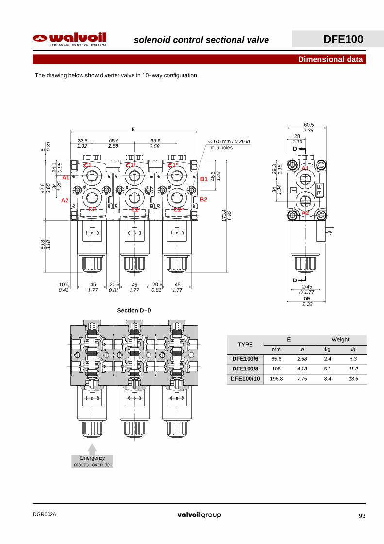
Dimensional data
8
3424
.1
92.6
80.8
10.6 45 20.6 45 20.6 45
65.665.633.5
E
46.3
173.
4
28
60.5
59
29.3
34
45∅
The drawing below show diverter valve in 10--way configuration.
C1
C2
C1’
C2’
C1”
C2”
B1
B2
A1
A2
A1
A2
Section D--D
D
D
Emergencymanual override
3.65
0.95
1.35
3.18
0.42 1.77 0.81 1.77 0.81 1.77
0.31 1.32 2.58 2.58
1.82
6.83
nr. 6 holes∅ 6.5 mm / 0.26 in
2.38
1.10
1.15
1.34
591.77∅
2.32
solenoid control sectional valve DFE100
DGR002A 93
TYPEE Weight
TYPEmm in kg lb
DFE100/6 65.6 2.58 2.4 5.3
DFE100/8 105 4.13 5.1 11.2
DFE100/10 196.8 7.75 8.4 18.5
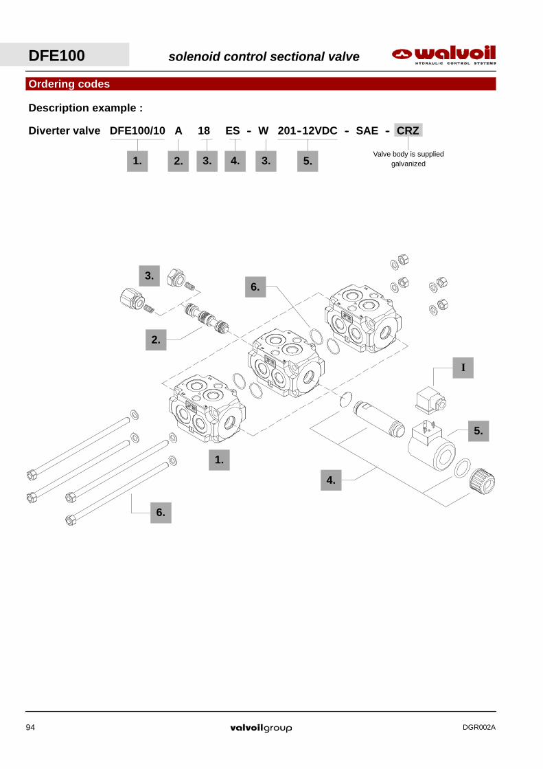
DFE100 solenoid control sectional valve
DGR002A94
Valve body is suppliedgalvanized
Diverter valve DFE100/10 A 18 ES -- W 201--12VDC -- SAE -- CRZ
Ordering codes47.
Description example :
1. 2. 3. 4. 5.3.
1.
4.
3.
2.
5.
I
6.
6.
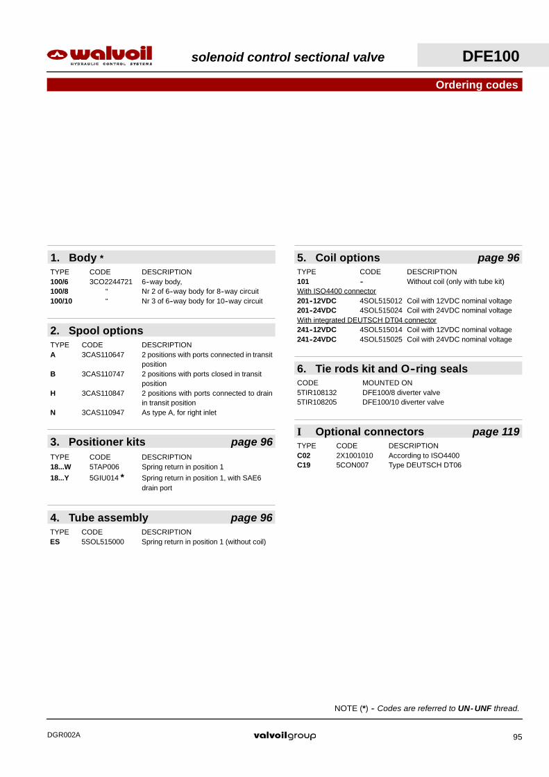
Ordering codes
NOTE (*) -- Codes are referred to UN- UNF thread.
TYPE CODE DESCRIPTIONC02 2X1001010 According to ISO4400C19 5CON007 Type DEUTSCH DT06
I Optional connectors page 119
1. Body *TYPE CODE DESCRIPTION100/6 3CO2244721 6--way body,100/8 “ Nr 2 of 6--way body for 8--way circuit100/10 “ Nr 3 of 6--way body for 10--way circuit
3. Positioner kits page 96TYPE CODE DESCRIPTION18...W 5TAP006 Spring return in position 1
18...Y 5GIU014 * Spring return in position 1, with SAE6drain port
4. Tube assembly page 96TYPE CODE DESCRIPTIONES 5SOL515000 Spring return in position 1 (without coil)
5. Coil options page 96TYPE CODE DESCRIPTION101 -- Without coil (only with tube kit)With ISO4400 connector201--12VDC 4SOL515012 Coil with 12VDC nominal voltage201--24VDC 4SOL515024 Coil with 24VDC nominal voltageWith integrated DEUTSCH DT04 connector241--12VDC 4SOL515014 Coil with 12VDC nominal voltage241--24VDC 4SOL515025 Coil with 24VDC nominal voltage
2. Spool optionsTYPE CODE DESCRIPTIONA 3CAS110647 2 positions with ports connected in transit
positionB 3CAS110747 2 positions with ports closed in transit
positionH 3CAS110847 2 positions with ports connected to drain
in transit positionN 3CAS110947 As type A, for right inlet
6. Tie rods kit and O--ring sealsCODE MOUNTED ON5TIR108132 DFE100/8 diverter valve5TIR108205 DFE100/10 diverter valve
solenoid control sectional valve DFE100
DGR002A 95

M20
x1
87.3
23
3.44
0.91
Manual tightening;max. torque 6.6 Nm / 4.9 lbft
Wrench 2020 Nm / 14.7 lbft
Push for manualoverride
54
452353.7
2.11
0.91
2.13
1.77
Operating featuresPlunger stroke : 7.1 mm / 0.28 in. . . . . . . . . . . . .
Solenoid parts
ES tube assemply
Coil options
With ISO4400 connector(weather protection IP65)
With integrated DEUTSCH 04 connector(weather protection IP67)
Needs C19 connector,see page 119.
Needs C02 connector,see page 119.
Thermoplasticprotective covering
Operating featuresNominal voltage : 12VDC / 24VDC. . . . . . . . . . .Nominal voltage tolerance : ±10%. . .Power rating : 38 W. . . . . . . . . . . . . .Duty cycle : 100%. . . . . . . . . . . . . . . .Weather protection : Depending on connector. . . . . . . . .
typeCoil insulation : Class H. . . . . . . . . . . . .
Spring return in position 1 with plug.
18W kit 18Y kitSpring return in position 1, with SAE6 joint for drain.
Positioner kits
1 2 1 2L
23
L
Return spring
Plug: wrench 24 -- 42 Nm / 31 lbft
8Return spring0.31
0.91
SA
E6
Joint: wrench 24 -- 42 Nm / 31 lbft
DFE100 solenoid control sectional valve
DGR002A96

solenoid control sectional valve DFE140
DGR002A 97
TYPEE Weight
TYPEmm in Kg lb
DFE140/6 68 2.68 4.6 10.1
DFE140/8 136 5.35 9.5 20.9
DFE140/10 204 8.03 14.4 31.7
With valves E WeightWith valvesblock mm in Kg lb
DFE140/6 122 4.80 7.8 17.2
DFE140/8 190 7.48 12.5 27.6
DFE140/10 258 10.16 17.6 38.8
107
13.4
120
95
4043
12 44 24 44 19 40
190.
5
260.
5
34 68 61
F
E
8.8
68
44 24
Dimensional data
38
75
8.5
4321
81.5
48
28
B1
B2
The drawing below show diverter valve in 10--way configuration with anti--shock valves block.
D
D
Section D--D
Emergencymanual override
2.95
1.89
1.69
0.83
0.33
1.10
1.50
3.21
1.34 2.68 2.68 2.40
4.21
0.53
4.72
3.74
1.57
1.69
0.35
0.47 1.73 1.73 1.730.94 0.94 0.75 1.57
7.5
10.2
6
C1
C2
C1’
C2’
C1”
C2”
B1
B2
A1
A2

DFE140 solenoid control sectional valve
DGR002A98
Valve body is suppliedgalvanized
Ordering codes50.
2.
1.
Diverter valve DFE 140 / 10 B 18 ES . P3 (D4--185) -- W 201--12VDC -- SAE -- CRZ *
2. 3. 4. 5.
3.
6.
W
Y
7.3.
Valve setting in barDescription example :
8.
8.
1.
4.
I
7.
8.
5.
6.

solenoid control sectional valve DFE140
DGR002A 99
I Optional connectors page 119
8. Tie rods kit and O--ring seals
7. Coil options page 101
6. Anti--shock valve page 102
Ordering codes
NOTE (*) -- Codes are referred to UN- UNF thread.
TYPE CODE DESCRIPTION101 Without coil (only with tube kit)With ISO4400 connector201--12VDC 4SOL519112 Coil with 12VDC nominal voltage201--24VDC 4SOL519124 Coil with 24VDC nominal voltage201--20VDC 4SOL519120 Coil with 20VDC nominal voltage
(for 24VAC): need C04 connector201--94VDC 4SOL519094 Coil with 94VDC nominal voltage
(for 110VAC): need C04 connector201--192VDC 4SOL519192 Coil with 192VDC nominal voltage
(for 220VAC): need C04 connectorWith flying leads and DEUTSCH DT04 connector241--12VDC 4SOL519412 Coil with 12VDC nominal voltage241--24VDC 4SOL519424 Coil with 24VDC nominal voltage
CODE MOUNTED ON5TIR108121 DFE140/6 with P3 valves block5TIR108134 DFE140/85TIR108189 DFE140/8 with P3 valves block5TIR108202 DFE140/10
TYPE CODE DESCRIPTIONC02 2X1001010 According ISO4400C04 2X1001040 According to ISO4400 with rectifierC19 5CON007 Type DEUTSCH DT06
With fixed setting: setting is referred to valve openingTYPE CODE DESCRIPTION(D2--80) X005125095 Setting 80 bar / 1150 psi(D3--125) X005125145 Setting 125 bar / 1800 psi(D3--140) X005125155 Setting 140 bar / 2050 psi(D3--170) X005125190 Setting 170 bar / 2450 psi(D4--185) X005125216 Setting 185 bar / 2700 psi(D4--210) X005125245 Setting 210 bar / 3050 psi(D4--240) X005125270 Setting 240 bar / 3500 psi
5. Valves block * page 102
4. Tube assembly page 100
3. Positioner kits page 100
2. Spool option
1. Body *TYPE CODE DESCRIPTION140/6 3CO2280302 6--way body140/8 “ Nr 2 of 6--way body for 8--way circuit140/10 “ Nr 3 of 6--way body for 10--way circuit
TYPE CODE DESCRIPTIONB 3CAS110740 2 positions with ports closed in transit
position
TYPE CODE DESCRIPTIONES 5SOL519001 Spring return in position 1 (without coil)
TYPE CODE DESCRIPTIONP3 3CO2780301 Cross--over anti--shock valve body
TYPE CODE DESCRIPTION18...W 5TAP005 Spring return in position 1
18...Y 5GIU011* Spring return in position 1, with SAE6drain port
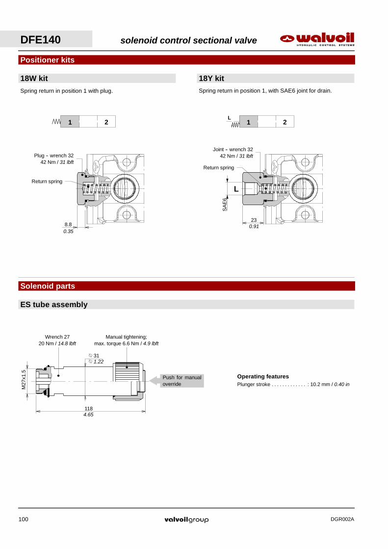
Manual tightening;max. torque 6.6 Nm / 4.9 lbft
Wrench 2720 Nm / 14.8 lbft
M27
x1.5
31
1184.65
1.22
Operating featuresPlunger stroke : 10.2 mm / 0.40 in. . . . . . . . . . . . .
Push for manualoverride
Spring return in position 1 with plug.
18W kit 18Y kitSpring return in position 1, with SAE6 joint for drain.
Positioner kits
1 2 1 2L
23
L
Solenoid parts
ES tube assembly
Return spring
Plug -- wrench 3242 Nm / 31 lbft
8.80.35
Return spring
Joint -- wrench 3242 Nm / 31 lbft
SA
E6
0.91
DFE140 solenoid control sectional valve
DGR002A100
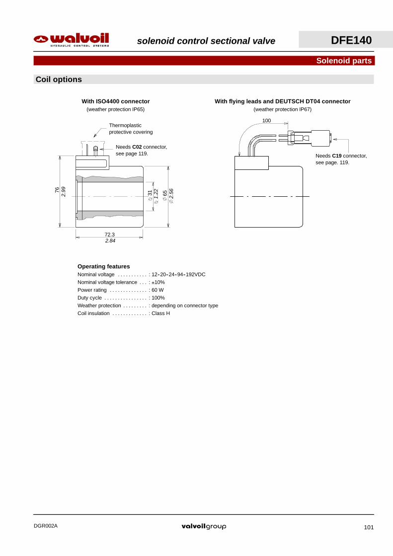
With flying leads and DEUTSCH DT04 connector(weather protection IP67)
100
Needs C19 connector,see page. 119.
3176
65
72.3
2.99
2.56
1.22
2.84
Needs C02 connector,see page 119.
With ISO4400 connector(weather protection IP65)
Thermoplasticprotective covering
Solenoid parts
Coil options
Operating featuresNominal voltage : 12--20--24--94--192VDC. . . . . . . . . . .Nominal voltage tolerance : ±10%. . .Power rating : 60 W. . . . . . . . . . . . . .Duty cycle : 100%. . . . . . . . . . . . . . . .Weather protection : depending on connector type. . . . . . . . .Coil insulation : Class H. . . . . . . . . . . . .
solenoid control sectional valve DFE140
DGR002A 101

A1 B1
B2A2
Hydraulic circuit
¡ ©
0
100
200
300
400
0 30 60 90Flow
Pre
ssur
e
(l/min)
(bar)
Anti--shock valves performance data(setting: 80--125--140--170--185--210--240 bar /1150--1800--2050--2450--2700--3050--3500 psi)
P3 block complete with anti--shock valves
7 40
54
9545
.1
190.
5
A1
A2
B1
B2
Wrench 2742Nm / 31 lbft
33.1
75
8.5
4321
D
D
B1
B2
Section D--DD
D
Anti--shock valve ¡
Anti--shock valve©1.30
1.78
3.74 7.5
1.57
2.13
0.28
1.69
0.83 ∅
0.33
∅
2.95
5 10 15 (US gpm)20
(psi)
4500
3000
1500
DFE140 solenoid control sectional valve
DGR002A102

rotary control valve DH
DGR002A 103
Contents
Working conditions 104. . . . . . . . . . . . . . . . . . . . . . . . . . . . . . .
Hydraulic circuit 105. . . . . . . . . . . . . . . . . . . . . . . . . . . . . . . . . .
DH5 106. . . . . . . . . . . . . . . . . . . . . . . . . . . . . . . . . . . . . . . . . . . .
DH10 107. . . . . . . . . . . . . . . . . . . . . . . . . . . . . . . . . . . . . . . . . . .
DH20 108. . . . . . . . . . . . . . . . . . . . . . . . . . . . . . . . . . . . . . . . . . .
DH25 109. . . . . . . . . . . . . . . . . . . . . . . . . . . . . . . . . . . . . . . . . . .
DH30 111. . . . . . . . . . . . . . . . . . . . . . . . . . . . . . . . . . . . . . . . . . .

Working conditions
This catalogue shows technical specifications and diagrams measured with mineral oil of 46 mm2/s -- 46 cSt viscosity aat 40°C --
104°F temperature. DH rotary spool diverter valve position cannot be changed when valve is pressurized.
Designation
Standard threads
Diverter valve DH10 / 3 A
Circuit type
Valve type
Nr. of ways
DH rotary control valve
DGR002A104
DH5 DH10 DH20 DH25 DH30N. of available ways 3--4--6--8 3--4--6--8 3--4--6--8 3--4--6--8 3--6
Nominal flow rating 60 l/min16 US gpm
90 l/min24 US gpm
140 l/min37 US gpm
200 l/min53 US gpm
280 l/min74 US gpm
Operating pressure(maximum)
315 bar4600 psi
315 bar4600 psi
315 bar4600 psi
250 bar3600 psi
210 bar3050 psi
Internal leakage A(B)→T ∆p=100 bar 1450 psi with fuidand valve at 40°C − 104°F
3 cm3/min0.18 in3/min
3 cm3/min0.18 in3/min
3 cm3/min0.18 in3/min
3 cm3/min0.18 in3/min
3 cm3/min0.18 in3/min
Hydraulic fluid Mineral base oil
Fluid temperature with NBR seals from --20°C to 80°C / from --4°F to 176°F
with FPM seals from --20°C to 100°C / from --4°F to 212°F
Viscosity operating range from 15 to 75 mm2/s -- from 15 to 75 cSty
minima 12 mm2/s -- 12 cSt
massima 400 mm2/s -- 400 cS
Max. level of contamination --/19/16 -- ISO 4406 / NAS 1638 -- class10
Ambient temperature forworking conditions from --40°C to 60°C / from --40°F to 140°F
NOTE -- For different working conditions please contact Sales Dept
REFERENCE STANDARDS
BSP UN--UNF METRIC
THREADACCORDING TO
ISO 228/1 ISO 263 ISO 262 ISO 262ACCORDING TO BS 2779 ANSI B1.1 unified
CAVITYACCORDING TO
ISO 1179 11926 9974--1 6149ACCORDING TO SAE J1926 J2244
DIN 3852--2shape X or Y
3852--1shape X or Y
PORTS THREAD
ALL PORTS BSP UN--UNF
DH5 G 3/8 3/4--16 (SAE 8)
DH10 G 1/2 7/8--14 (SAE 10)
DH20 G 3/4 1 1/16--12 (SAE 12)
DH25 G 1 1 5/16--12 (SAE 16)
DH30 G 1 1/2 1 7/8--12 (SAE 24)
NOTE -- For different thread contact Sales Department

rotary control valve DH
DGR002A 105
0
5
10
15
20
0 80 160 240 320
Spool
Pre
ssur
e
(bar)
(l/min)
DH30
Spool A
Spool B200
100
(psi)
20 40 60 (US gpm)80
0
5
10
15
20
0 60 120 180 240
Flow
Pre
ssur
e
(bar)
(l/min)
DH25
Spool B
Spool A
200
100
(psi)
20 40 60 (US gpm)
0
5
10
15
20
0 40 80 120 160
Flow
Pre
ssur
e
(bar)
(l/min)
DH20
Spool B
Spool A
200
100
(psi)
10 20 30 (US gpm)40
0
5
10
15
20
0 30 60 90 120
Flow
Pre
ssur
e
(bar)
(l/min)
DH10
Spool B
Spool A
200
100
(psi)
10 20 30 (US gpm)
0
5
10
15
20
0 20 40 60 80
Flow
Pre
ssur
e
(bar)
(l/min)
DH5
Spool B
Spool A
200
100
(psi)
5 10 15 (US gpm)20
3--way and 6--way6--way diverter valve is obtained by coupling two 3--way
bodies using assembling kit.
4--way and 8--way8--way diverter valve is obtained by coupling two 4--way
bodies using assembling kit.
A B
P
1 201 2
A B
P
0
Hydraulic circuit
Spool type BSpool type A Spool type BSpool type A
1 2
A B
P
0
T
1 20
A B
P T
Knob type 02; standardwith spool type B
Knob type 01; standardwith spool type A
Spool
4A 4B3A 3B
1 2 1 2 1 2
Spool
1 2
Performance data
Pressure drop versus flow P→A(B): spool in position 1 (2)
3--way and 6--way valves
4--way and 8--way valves
P
A B
P
A B
P
A B
T
P
A B
T
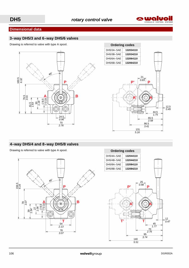
DH5 rotary control valve
DGR002A106
12
45
95
140
A’
P’ P
A
T’ T
25
70
0.98
0.47
1.77
2.76
3.74
5.51
12.5
44.5
86.5
131
A’
P’ P
A
21
65.5
0.49
1.75
2.58
3.41
5.16
0.83
Ordering codes
DH5/4A--SAE 132044110
DH5/4B--SAE 132044210
DH5/8A--SAE 132084110
DH5/8B--SAE 132084210
Ordering codes
DH5/3A--SAE 132034110
DH5/3B--SAE 132034210
DH5/6A--SAE 132064110
DH5/6B--SAE 132064210
4--way DH5/4 and 8--way DH5/8 valves
78
54
8,5
27
39
78
156.
5
A B
P
T
∅
6.16
3.07
1.54 1.
06 0.33
∅
2.13
3.07
Drawing is referred to valve with type A spool.
8.5
30
41.5
70
24.5
76.5
160.
5
∅
A B
P
3--way DH5/3 and 6--way DH5/6 valves
6.32
3.01
1.63 1.
18 0.33
∅
0.96
2.76
Drawing is referred to valve with type A spool.
Dimensional data
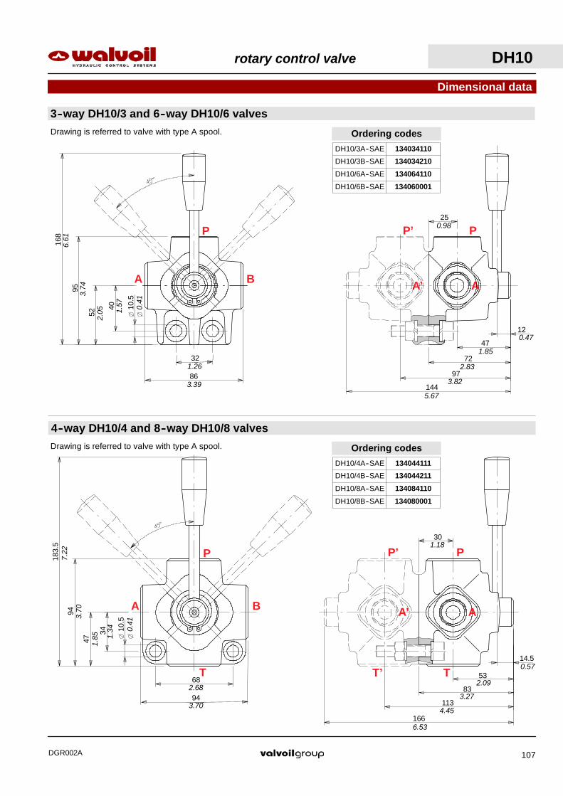
rotary control valve DH10
DGR002A 107
166
113
0.57
A’
P’ P
A
T’ T
30
83
53
1.18
6.53
4.45
3.27
2.09
14.5
Ordering codes
DH10/4A--SAE 134044111
DH10/4B--SAE
DH10/8A--SAE 134084110
DH10/8B--SAE 134080001
134044211
144
97
47
12
A’
P’ P
A
25
72
0.47
1.85
2.83
3.82
5.67
0.98
Ordering codes
DH10/3A--SAE 134034110
DH10/3B--SAE 134034210
DH10/6A--SAE 134064110
DH10/6B--SAE 134060001
4--way DH10/4 and 8--way DH10/8 valves
94
68
183.
5
94
47
34 10.5
A B
P
T2.68
3.70
7.22
3.70
1.85 1.
34 0.41
Drawing is referred to valve with type A spool.
3--way DH10/3 and 6--way DH10/6 valves
168
95
52
40 10.5
32
86
A B
P
6.61
3.74
2.05 1.
57 0.41
3.39
1.26
Drawing is referred to valve with type A spool.
Dimensional data
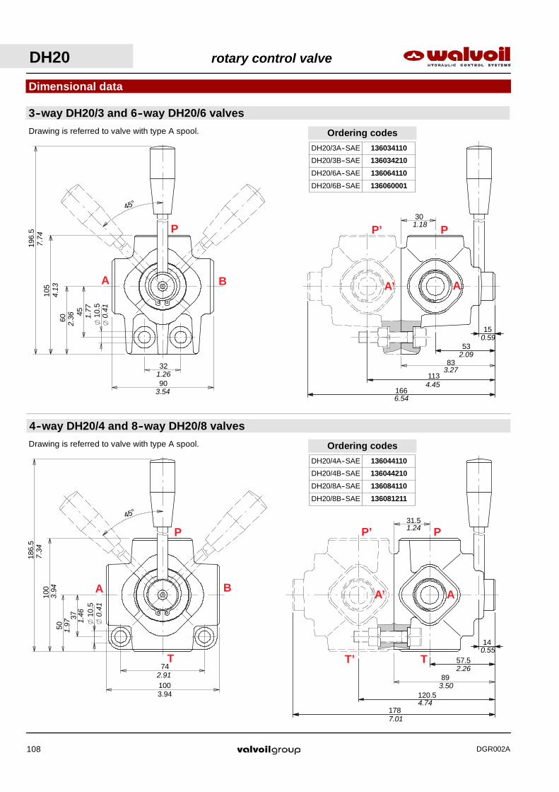
DH20 rotary control valve
DGR002A108
178
120.5
57.5
14
A’
P’ P
A
T’ T
89
31.51.24
0.55
2.26
3.50
4.74
7.01
166
113
53
15
A’
P’ P
A
30
83
1.18
6.54
4.45
3.27
2.09
0.59
Ordering codes
DH20/4A--SAE 136044110
DH20/4B--SAE 136044210
DH20/8A--SAE 136084110
DH20/8B--SAE 136081211
Ordering codes
DH20/3A--SAE 136034110
DH20/3B--SAE 136034210
DH20/6A--SAE 136064110
DH20/6B--SAE 136060001
4--way DH20/4 and 8--way DH20/8 valves
74
100
186.
5
100
50
37 10.5
A B
P
T
7.34
3.94
1.97 1.
46 0.41
2.91
3.94
Drawing is referred to valve with type A spool.
3--way DH20/3 and 6--way DH20/6 valves
32
90
196.
5
105
60
45 10.5
A B
P
7.74
4.13
2.36 1.
77
0.41
1.26
3.54
Drawing is referred to valve with type A spool.
Dimensional data
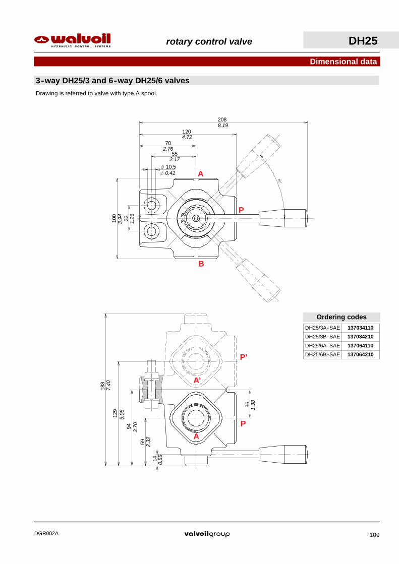
rotary control valve DH25
DGR002A 109
188
129
59
14
A’
P’
P
A
35
94
2.32
0.55
3.70
5.08
7.40
1.38
Ordering codes
DH25/3A--SAE 137034110
DH25/3B--SAE 137034210
DH25/6A--SAE 137064110
DH25/6B--SAE 137064210
3--way DH25/3 and 6--way DH25/6 valves
32100
208
70
120
55
10.5A
B
P
8.19
4.72
2.76
0.41
2.17
1.26
3.94
Drawing is referred to valve with type A spool.
Dimensional data

DH25 rotary control valve
DGR002A110
190
130
60
13.5
A’
T’
P
A
P’
T95
35
0.53
2.36
3.74
5.12
7.48
1.38
Ordering codesDH25/4A--SAE 137044110
DH25/4B--SAE 137044210
DH25/8A--SAE 137084110
DH25/8B--SAE 137084210
4--way DH25/4 and 8--way DH25/8 valves
88112
251
112
56
44
10,5
A
B
PT
9.88
4.41
2.20
1.73
0.41
3.46
4.41
Drawing is referred to valve with type A spool.
Dimensional data

rotary control valve DH30
DGR002A 111
Ordering codesDH30/3A--SAE 139034110
DH30/3B--SAE 139034210
DH30/6A--SAE 139064110
DH30/6B--SAE 139061211
232
162
70
15
A’
P’
P
A
46
116
9.13
6.38
4.57
2.76
0.59
1.81
3--way DH30/3 and 6--way DH30/6 valves
49130
282.5
150
85
65
10.5A
B
P
11.1
5.91
3.35
2.56
0.41
1.93
5.12
Drawing is referred to valve with type A spool.
Dimensional data

Diverter valve
DGR002A112
Product marking
walvoilDFE110/12P0681389
12A500002MADE IN ITALY
Production batch :P06 = production year (2006)81389 = progressive number
Product type(optional)
Part codeManifacture country :on demand it is possible to inserta customer reference:example Ref. 133453
Building firm
Marking example
Marking zone depending on valve type, as indicate below.
All Walvoil diverter valves are marked according to EN 982 normative.
This marking includes: building firm, part code, production batch and manufacture country.
2--way and 3--way DF mechanical control type 6--way DF mechanical control type
walvoilP0681389122050051
MADE IN ITALY
walvoilP068138912080031
MADE IN ITALY
2--way and 3--way DFE solenoid controlmonoblock type
walvoilP0681389
12A240022MADE IN ITALY
6--way DFE solenoid controlmonoblock type
1
2
walvoilP0681389
12A270034MADE IN ITALY

Diverter valve
DGR002A 113
Product marking
DH rotary control typeDFE140 solenoid control sectional type
DFE100 solenoid control sectional type
walvoilP0681389
12G060005MADE IN ITALY
walvoilP068138912F060005
DFE080 solenoid control sectional type
walvoilDFE140/6P0681389
12CMADE IN ITALY
walvoilP0681389132034110
MADE IN ITALY
DFE110 solenoid control monoblock type
walvoilDFE110/12P0681389
12A500002MADE IN ITALY
8--way DFE solenoid control monoblock type
walvoilP0681389
12B020025MADE IN ITALY
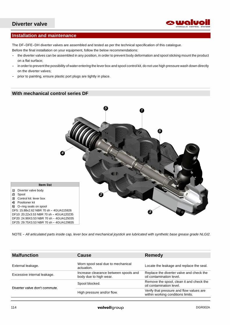
Installation and maintenance
Item list
1) Diverter valve body2) Spool3) Control kit: lever box4) Positioner kit5) O--ring seals on spoolDF5: 15.88x2.62 NBR 70 sh -- 4GUA115926DF10: 20.22x3.53 NBR 70 sh -- 4GUA120235DF20: 24.99X3.53 NBR 70 sh -- 4GUA125035DF25: 29.75X3.53 NBR 70 sh -- 4GUA129835
NOTE -- All articulated parts inside cap, lever box and mechanical joystick are lubricated with synthetic base grease grade NLGI2.
With mechanical control series DF
The DF--DFE--DH diverter valves are assembled and tested as per the technical specification of this catalogue.
Before the final installation on your equipment, follow the below recommendations:
-- the diverter valves can be assembled in any position, in order to prevent body deformation and spool sticking mount the product
on a flat surface;
-- in order to prevent the possibility of water entering the lever box and spool control kit, do not use high pressure wash down directly
on the diverter valves;
-- prior to painting, ensure plastic port plugs are tightly in place.
Diverter valve
DGR002A114
Malfunction Cause Remedy
External leakage. Worn spool seal due to mechanicalactuation. Locate the leakage and replace the seal.
Excessive internal leakage. Increase clearance between spools andbody due to high wear.
Replace the diverter valve and check theoil contamination level.
Diverter valve don’t commuteSpool blocked. Remove the spool, clean it and check the
oil contamination level.Diverter valve don’t commute.
High pressure and/or flow. Verify that pressure and flow values arewithin working conditions limits.

Diverter valve
DGR002A 115
Malfunction Cause Remedy
External leakage. Worn body seal due to mechanicalactuation Locate the leakage and replace the seal.
Excessive internal leakage. Increase clearance between spools andbody due to high wear.
Replace the diverter valve and check theoil contamination level.
Spool blocked. Remove the spool, clean it and check theoil contamination level.
Diverter valve don’t commuteCoil winding burnt. Replace the coil and check the supply
voltage value.Diverter valve don’t commute.
Uncorrected supply voltage. Test the electric circuit and check thesupply voltage value.
High pressure and/or flow. Verify that pressure and flow values arewithin working conditions limits.
Installation and maintenance
Item list
1) Diverter valve body2) Spool3) Coil4) Tube assembly (with O--ring seals)5) Lock ring6) Positioner kit, with or without drain7) O--ring seals on bodyDFE052: 17.17x1.78 NBR 70 sh -- 4GUA117218DFE10: 18.77x1.78 NBR 70 sh -- 4GUA118818DFE20: 23.47x2.62 NBR 70 sh -- 4GUA123526DFE110: 23.47x2.62 NBR 70 sh -- 4GUA123526
With ON/OFF solenoid control series DFE monoblock type

Installation and maintenance
Item list
1) Diverter valve body 10) O--ring seals on body2) Spool DFE080: 17.17x1.78 NBR 70 sh -- 4GUA1172183) Coil DFE100: 17.17x1.78 NBR 70 sh -- 4GUA1172184) Tube assemply (with O--ring seals) DFE140: 23.47x2.62 NBR 70 sh -- 4GUA1235265) Lock ring 11) O--ring seals between sections6) Positioner kit, with or without drain DFE080: 18.77x1.78 NBR 90 sh -- 4GUA3188187) Tie rods kit DFE100: 26.70x1.78 NBR 90 sh -- 4GUA3267188) Valves block (only for DFE140) DFE140: 28.30x1.78 NBR 90 sh -- 4GUA3283189) Anti--shock valves (only for DFE140)
With ON/OFF solenoid control series DFE sectional type
Diverter valve
DGR002A116
Malfunction Cause Remedy
Worn body seal. Locate the leakage and replace the seal.
External leakage.Worn section seal.
Locate the leakage and replace the seal.Be sure to tignten the tie rods to correctvalue.
Excessive internal leakage. Increase clearance between spools andbody due to high wear.
Replace the diverter valve and check theoil contamination level.
Spool blocked. Remove the spool, clean it and check theoil contamination level.
Diverter valve don’t commuteCoil winding burnt. Replace the coil and check the supply
voltage value.Diverter valve don’t commute.
Uncorrected supply voltage. Test the electric circuit and check thesupply voltage value.
High pressure and/or flow. Verify that pressure and flow values arewithin working conditions limits.

Diverter valve
DGR002A 117
Malfunction Cause Remedy
External leakage. Worn spool seal due to mechanicalactuation. Locate the leakage and replace the seal.
Excessive internal leakage. Increase clearance between spools andbody due to high wear.
Replace the diverter valve and check theoil contamination level.
Diverter valve don’t commuteSpool blocked. Remove the spool, clean it and check the
oil contamination level.Diverter valve don’t commute.
High pressure and/or flow. Verify that pressure and flow values arewithin working conditions limits.
Installation and maintenance
Item list
1) Diverter valve body2) Rotative spool3) Handlever4) Upper O--ring sealDH5: 20.29X2.62 NBR 90 sh -- 4GUA320326DH10: 24.99X3.53 NBR 90 sh -- 4GUA325035DH20: 29.75X3.53 NBR 90 sh -- 4GUA329835DH25: 34.52X3.53 NBR 90 sh -- 4GUA334535DH30: 49.21X3.53 NBR 90 sh -- 4GUA3492355) Bottom O--ring sealDH5: 15.08X2.62 NBR 90 sh -- 4GUA315126DH10: 18.64X3.53 NBR 90 sh -- 4GUA318635DH20: 23.39X3.53 NBR 90 sh -- 4GUA323435DH25: 28.17X3.53 NBR 90 sh -- 4GUA328235DH30: 42.86X3.53 NBR 90 sh -- 4GUA342935
With rotary control series DH

Diverter valve
DGR002A118
MECHANICAL CONTROL DIVERTER VALVE VALVESTHREADS TYPE DF5 DF10 DF20 DF25
BSP G 3/8 G 1/2 G 3/4 G 1
With O--Ring seal 35 / 25.8 50 / 37 90 / 66.4 100 / 73.8
With copper washer 40 / 29.5 60 / 44.3 60 / 44.3 90 / 66.4
With steel and rubberwasher 30 / 22 60 / 44.3 70 / 51.6 100 / 73.8
UN--UNF 3/4--16 (SAE 8) 7/8--14 (SAE 10) 1 1/16--12 (SAE 12) 1 5/16--12 (SAE 16)
With O--Ring seal 50 / 37 60 / 44.3 95 / 70 150 / 111
SOLENOID CONTROL MONOBLOCK DIVERTER VALVESDFE052 DFE10 DFE110 DFE20
THREADS TYPE Ports Drain Drain * Ports Drain Ports Drain Ports Drain
BSP G 3/8 G 1/4 G 1/4 G 1/2 G 1/4 G 1/2 G 1/4 G 3/4 G 1/4
With O--Ring seal 35 / 25.8 20 / 14.8 20 / 14.8 50 / 37 20 / 14.8 50 / 37 20 / 14.8 90 / 66.4 20 / 14.8
With copper washer 40 / 29.5 25 / 18.4 25 / 18.4 60 / 44.3 25 / 18.4 60 / 44.3 25 / 18.4 60 / 44.3 25 / 18.4
With steel and rubberwasher 30 / 22 16 / 11.8 16 / 11.8 60 / 44.3 16 / 11.8 60 / 44.3 16 / 11.8 70 / 51.6 16 / 11.8
UN--UNF 3/4--16(SAE 8)
9/16--18(SAE 6)
7/16--20(SAE4)
7/8--14(SAE 10)
9/16--18(SAE 6)
7/8--14(SAE 10)
9/16--18(SAE 6)
1 1/16--12(SAE 12)
7/16--20(SAE4)
With O--Ring seal 50 / 37 30 / 22.1 15 / 11 60 / 44.3 30 / 22.1 60 / 44.3 30 / 22.1 95 / 70 15 / 11
(*) drain only for DFE052/8
SOLENOID CONTROL SECTIONAL DIVERTER VALVESDFE080 DFE100 DFE140
THREADS TYPE Bocche Drenaggio Bocche Drenaggio Bocche Drenaggio
BSP G 1/4 G 1/4 G 3/8 G 1/4 G 1/2 G 1/4
With O--Ring seal 20 / 14.8 20 / 14.8 35 / 25.8 20 / 14.8 50 / 37 20 / 14.8
With copper washer 25 / 18.4 25 / 18.4 40 / 29.5 25 / 18.4 60 / 44.3 25 / 18.4
With steel and rubberwasher 16 / 11.8 16 / 11.8 30 / 22 16 / 11.8 60 / 44.3 16 / 11.8
UN--UNF 7/16--20(SAE 4)
7/16--20(SAE 4)
7/8--14(SAE 10)
9/16--18(SAE 6)
7/8--14(SAE 10)
9/16--18(SAE 6)
With O--Ring seal 15 / 11 15 / 11 50 / 37 30 / 22.1 60 / 44.3 30 / 22.1
ROTARY CONTROL DIVERTER VALVESTHREADS TYPE DH5 DH10 DH20 DH25 DH30
BSP G 3/8 G 1/2 G 3/4 G 1 G 1 1/2
With O--Ring seal 35 / 25.8 50 / 37 90 / 66.4 100 / 73.8 120 / 44.3
With copper washer 40 / 29.5 60 / 44.3 60 / 44.3 90 / 66.4 100 / 73.8
With steel and rubberwasher 30 / 22 60 / 44.3 70 / 51.6 100 / 73.8 120 / 44.3
UN--UNF 3/4--16(SAE 8)
7/8--14(SAE 10)
1 1/16--12(SAE 12)
1 5/16--12(SAE 16)
1 7/8--12(SAE 24)
With O--Ring seal 50 / 37 60 / 44.3 95 / 70 150 / 111 210 / 155
Installation and maintenance
Fittings tightening torque -- Nm / lbftThese torque are recommended.
Assembly tightening torque depends on many factors, including lubrication, coating and surface finish. The manufacturer shall be
consulted.

2P+T according to ISO4400 / EN175301--803With bridge rectifier, to use with VAC supply.
50.4
40.5
18
1 39.7
35
28
PG09
Type C04 code: 2X1001040
1.59
1.10
0.71
1.98
1.38
1.56
28.4
15
2P male case with female endtype Deutsch DT06--2S
Type C19 code: 5CON007
1.12
0.59
2P female case with female endtype AMP “Junior--Power--Timer”
Type C08 code: 5CON003
37.5
11.817
16 0.63
0.67 0.46
1.48
23 17.50.91 0.69
Accessories
Optional connectors
50
33
2P+T according toISO4400 / EN175301--803
12
PG09
30
Type C02 code: 2X1001010
1.30
1.97
1.18
Diverter valve
DGR002A 119
Type Poles Nominal voltage Nominalcurrent
Permitted conductorsection range
Permitted cablediameter range
Weatherprotection
C02 2P + T 250 VAC / 300 VDC 10 A max.1.5 mm2 / max.0.0023 in2 6--8 mm / 0.24--0.31 in IP65
C04 2P + T / 10 A max.1.5 mm2 / max.0.0023 in2 6--8 mm / 0.24--0.31 in IP65
C08 2P 250 VAC 12 A 0.5--1 mm2 / 0.00077--0.00155 in2 1.4--1.6 mm / 0.055--0.063 in IP65
C19 2P / 13 A 1--1.2 mm2 / 0.00155--0.00186 in2 2.2--3.5 mm / 0.088--0.14 in IP67

WALVOIL S.P.A.
42100 REGGIO EMILIA • ITALY • VIA ADIGE, 13/DTEL. +39.0522.932411 • FAX +39.0522.300984
E--MAIL: [email protected] • HTTP: //WWW.WALVOIL.COM
SERVIZIO COMMERCIALE
TEL. +39.0522.932555 • FAX +39.0522.932455
D1409808IDGR002A