div wright-patterson ehe~lk · a-0-a103 657 foreign4 technology div wright-patterson afr oh f/g...
TRANSCRIPT
A-0-A103 657 FOREIGN4 TECHNOLOGY DIV WRIGHT-PATTERSON AFR OH F/G 20/7TIE ANNUAL REPORT OF THE INSTITUTE OF ATOMIC ENERGY (SELECTED P-ETC(U)
UCAUGS 81UNCLASSIFIED FTO-IO(RS)T 0526-81 N
EhE~lK

/FTD-ID(RS)T-0526-81
FOREIGN TECHNOLOGY DIVISION
THE ANNUAL REPORT OF THE INSTITUTE OF ATOMIC ENERGY
(Selected Pages)
D DTIC~SEP 218
LmApproved for public release;~distribution unlimited.
4_1
-

EDITED TRANSLATIONLD-ID(RS)T-0526-8 12 -got1!
MICROFICHE NR: FTD-81-C-000759
Qj HE ANNUAL REPORT OF THE INSTITUTE OF ATOMIC;NERTYx (Sefected Pages). .Eng
Sou Attacment to IR 5 300 0026-81
P4P., 58-6 2~p
Country of origin: China *
Translated by: SCITRAN f/F33657-78-D-0619 *-
Requester: FTD/TQTDApproved for public release; distributionunlimited.
THIS TRANSLATION IS A RENDITION OF THE ORIGI.NAL FOREIGN TEXT WITHOUT ANY ANALYTICAL O REDITORIAL COMMENT. STATEMENTS OR THEORIES PREPARED BY:ADVOCATED OR IMPLIED ARE THOSE OF THE SOURCEAND DO NOT NECESSARILY REFLECT THE POSITION TRANSLATION DIVISIONOR OPINION OF THE FOREIGN TECHNOLOGY DI. FOREIGN TECHNOLOGY DIVISIONVISION. WP-AFB, OHIO.
FTD -ID(RS)T-0526-81 Date 12 Aug 1981
77T /± 777=9w
A!:::UAL REPORT OF TILE INSTITUTE OF ATO1MIC ENERGY
LJE"...... FOW ELECTfEON PULSE ACCELERATOR
. le Yen
Preface
In order to strengthen the scientific and technical interchange, it was
decided to publish "the Annual Report of the Institute of Atomic Energy"
(ARIAE). This issue mainly introdncL. the progrcsses in scientific research
and production as well as the situation of academic exchange of our insti-
tute in 1979 (from Jan. I to Dec. 31). IAE, situated in the south-westcrn
suburbs of Beijing, is a multidisciplinary institute of nuclear science. Its
predecessor was the Institute of Modern Physics of the Chinese Academy of
Sciences, which was founded in 1950. It was renamed the Institute of
Atomic Energy in 1958. The famous nuclear physicists, the late Prof. Wu
Youxun and Prof. Qian Sanqiang had been the directors of this Institute
successively. The director today is the well-known nuclear physicist, Prof.
Wang Ganchang
At present,the main fields of scientific research in the IAE areg nuclear
physics, accelerator, radiochemistry, radiochemical engineering, reactor,
isotopes preparation etc. There are 21. laboratories in the Institute. The
main facilities in IAE are, a heavy-water research reactor, a swimming-
pool light-water reactor, three accelerators, two 180" electromagnetic
separators, several zero-energy reactors and various kinds of hot cells used
for the examination of irradiated reactor materials, the nuclear fuel
reprocessing and the production of radioactive isotopes. Besides these, a
linear electron accelerator with high current and short pulse is under
construction. A tandem accelerator, type HI-13, will be imported from
abroad as well, Aeer~on
NTIS GlI%-DTIC TA4R
J".;t ifticct t, ,C1
Jutitc~ ir o
, 7....

T.his iNsue consists uf ii piarts. Abstructs of over :iIm articles are
preseiited. It can1 be sulzamil ited bs follows.
1. In the research on basic scienco and tho foundarnntats of applied sci-ence,* some notuorothy progrc;ss has boen ,:ido* For example, by using a
boine-niade scniicoaductor dctcctor spectroineter with a nmguetic analyzer
for piarticle identification at Van de Graiff accelerator, the intermediate
structure in nuclear reaction hias been studicd and a possible intermediate
resonance with a widtL of about 2GokeV wa% discovered in the excitationfunction Of 26Si (d,p))29Si reaction at E8 1.90 MeV. After detailed inca-
surtment and analysis, a gross structure in the excitation curve of the)"Io nn) 1 reaction around E.=2.7 MseV was observed. Combiningwith the experimental investigation ,the quasi free cluster L-Dockout reactions
in OLi were asnalysed 'with DWIA and PW]A. The results indicated thatthe OWVIA is superior. A calculation based on the precquilibrium emission
model with excitoui-phonon coupling gives good agreemnent with our expe-rimental data in the radiation capture cross section of fast neutron on235U, 5 GFe and 20SPb. A work about the relation between the quark-
quark interaction and the nucleon-nucleon interaction was initiated.Research on the inertial confinement for nuclear fusion with chargedparticle beam has been developed. The physical design and the preparation
of some components for high current electron LINAC have been performed.
The work of compilation, evaluation and measurement of nuclear
data has moved forward. The evaluation of neutron data in the resonanc e
region and the data of -y-ray production have been undertaken .The nucleardata library about the fission yields has been tentatively established ona NOVA-840 computer and the automatization of evaluation has been
realized. The first batch of group constants for thermal reac tor has been
prpduced as well.
Using the method of functional analysis, we have already investigated
the dominant cigenvalue of the neutron transport operator for the energy-
dependent physical system which has the isotropic scattering and/or fissionand contains the cavity, In this year, by. suitable mathematical treatment we
bave proved the existence of the dominant cigenvalue of the neutron trans-port integrodiffcrential B~oltzmann operator for the case of the Anisotropicscattering and/or fission. Thus we have solved one of the basic problemsin the neutron transport theory.
In 1079, the accuracy of the burnup measurement or the fuel elementwas improved by means of a variety of methods Including quantitative
1,nai!YS uf muiny fission f rtiv~snent eltnitnts, An extractioni process f eituriogthle e ~ raction of the transplutu'nium elements, N'p , Ami, Cmn aud the
f zfrineat eirments Tc, Sr. Cs, Im etc. from high level radioactivewaste wa'ter wits stiggestet!. Study of the adsorption property of a newsyntlittic thiourca chla~tt resiu on the nobkt metal ions indicated that
it can be usrd for the sirnultaucous trace determination of seven nqblonittat clements, %uch as Pd, Au, Pt etc. [Besides, study o the Appli-cation of crown compounds to the septrutica and analysis has been iziit!Mtcd,
For txptriments in renctor pbysics,after completing the investigation inthe pulsed neutron source technique, particular emphasis was laid on therelearCh Of staitiStical techuique And measuring the in-core neutron spectra.The precision in mueasuring the heat transfer of gas flow in pipes At hightemperature difference and that of sodium in distorted. structure was imp-roved. The dt~tcrminttion of the heat conductiVity Of U0 2 Pellet, thestudy on the creep of the uranium-aluminum alloy fuel element and therunning water corrosion test were carried out and better results were ob-tained,
For medical protection research, study on the -chromosome aberrationsof husuan lymphocytes induced in vitro by neutron irradiation has beenpursued.
2. Advances in the applied research serving to the national economy.For example, A prototype oil logging device based on the measurement ofinelastic scattering y-ray spectrak induced by neutrons had passed the fieldtest. Its ability in discriminating oil layers from water layers makes it anadvanced measuring tool for oil prospecting and exploitation. An zirconiasolid electrolyte analyser (type 20-101) based on the practical equation,suitable for the on-line analysis of oxygen concentration in a pure argonOr nitrogen syst em, achieved better sensitivity and accuracy. This projectjwon the third prize of invention awarded by the People's Republic of China.
Blesides, a lot of new' isotopes have been developed. Study on ex-traiction of 9'Mo- 9 0 -Tc generator, 1321'e-1321 generator and 133Xe physi-ological saline injection from fission products of 2"5U has been completed.Since their 4uality has come up to the international standard, they arePut into production and supplied to various customers at present. Over 10new varieties of labelled organic compounds and three new types of radio-Immunciassay kits in vitro have been tentatively supplied to medicine circles.14 respect of radioactive source, the new assortments, such as 5 Fc disc
sources, 2301u and 2 41Am winulur sources were added to the ctalu/ueofcommodities.
Study of the neutron transinulation doping (NTD) on silicon by rea-
ctor was initiated.
In brief, the applied research for the national economy now becomesan important domain of our Institute.
5. Some experimental facilities have boen con,;tructed, reconstructedor extonded and some electronic equipments have been prepared.The out-of-d;ited heavy water research reactQr as 'put into reconstru-
ction. The disassembly of the reactor, the lifting up and burial of theold reactor vessel, putting the new vessel to the right position and the
mounting of equipments and piping systems have been safely carried out.
As a result of close coordination of various departments and the adoptionof a series of effective steps, the disassembly of the reactor was performed
safely and smoothly. Moreover, a weaiih of experiences in the disassemblyof a reactor and the operation under intense radiation fields has been
accumulated. It is expected that after the reconstruction, the maximum
thermal neutron flux per unit power will be raised by 50%, the usable in-
core space for irradiation will be increased by 2.6 times and the excessreactivity will be increased by 3%, so it will be more suitable forcomprehensive uses of the reactor, such as radioactive isotope production,
various physical experiments, NTD silicon irradiation and fuel element test-ing.In the preparation of the prototype high current and short pulse electronLINAC, achievements have been obtained for the short pulse electron
gun and the adjustment of the cavity type coupler. The phase measurement,the power transmission of microwaves and the mounting of variousassemblies before the bunching section were completed. The beam currentwas extracted while there was accelerating electric field in the bunchingsection and the picture of high current was presented. Due to the closecooperation between theorists and experimentalists, many difficulties wereovercome. The improvement of the cyclotron continued in 1979. The speedand the precision in 'magnetic field measurements wre raised by means ofan home made automatic magnetometer.In the field of computer technology,a home made digital computer of model TQ-6 in the rank of 106/s was
successfully installed and adjustedand officially put into operation early inNovember,t979.Besides,we have adopted measures to extend the applicationof the swimming-pool light-water reactor, such as the prod%.ction of radio-active isotopes Cr, P, Mo-Tc etc, activation analysis and some nuclear
iv
physics expesimnents. In the field of nuclear clvctronic , a photogrii, Lic
recording oscilloscope for siclI,L pulse hijd the interface of 1024 multichan-
ncl enalyzcr with a t, bl, computer of viodel "Great wull 203" wcie set
up. A data acqui.itin 1*ad processing system based on a computer passedthe test for separate sinfglc-user terminal.'he pieparation of the staudL~rd
NIM plug-in units and the study of the CAMAC system moved forward.In
ordcr to extend the production of rbdioactive i4otopes, a new building forproducig jind tetiuig isotopes was nearly completed.
In 1979, the academic exchange was quite active. In our Institute,
after the symposium on nuclear physics in 1q78, symposiums on reactor,
chemistry, mathematics, detectors and nuclear electronics, clectrophysics
and ri.diation protection were successively held early in 1979. There were
398 articles presented in these symposiums. The number of various confe-
rences, meetiugs and symposiums that we took part in totalled 259. The
international academic exchange also became increasingly strengthened
in this years 98. foreign friends visited our Institute and 54 lectures and
discussions were held. These academic pursuits enlivened the academic
atmosphere, promoted the academic exchange and improved the friendship
between scientists from different countries.
In consequence of the lack of experience, shortcomings and mistakes in
this Annual Report are unavoidable, so advices and criticisms are surely
welcome.
Editor
I . " . o o ... . . .. .
INTENSE FLOW ELECTRON PULSE ACCELERATOR
by
THE CHARGED PARTICLE INERTIA CONTROL RESEARCH GROUP
Translated from 1979 Inst. of Atomic Energy Annual Report, Beijing,
P.R.C.
CHAPTER 6. INTENSE FLOW ELECTRON PULSE ACCELERATOR
1. The physical and engineering designs of the intense flow
electron pulse acceterator.
(by charged particle inertia control research group)
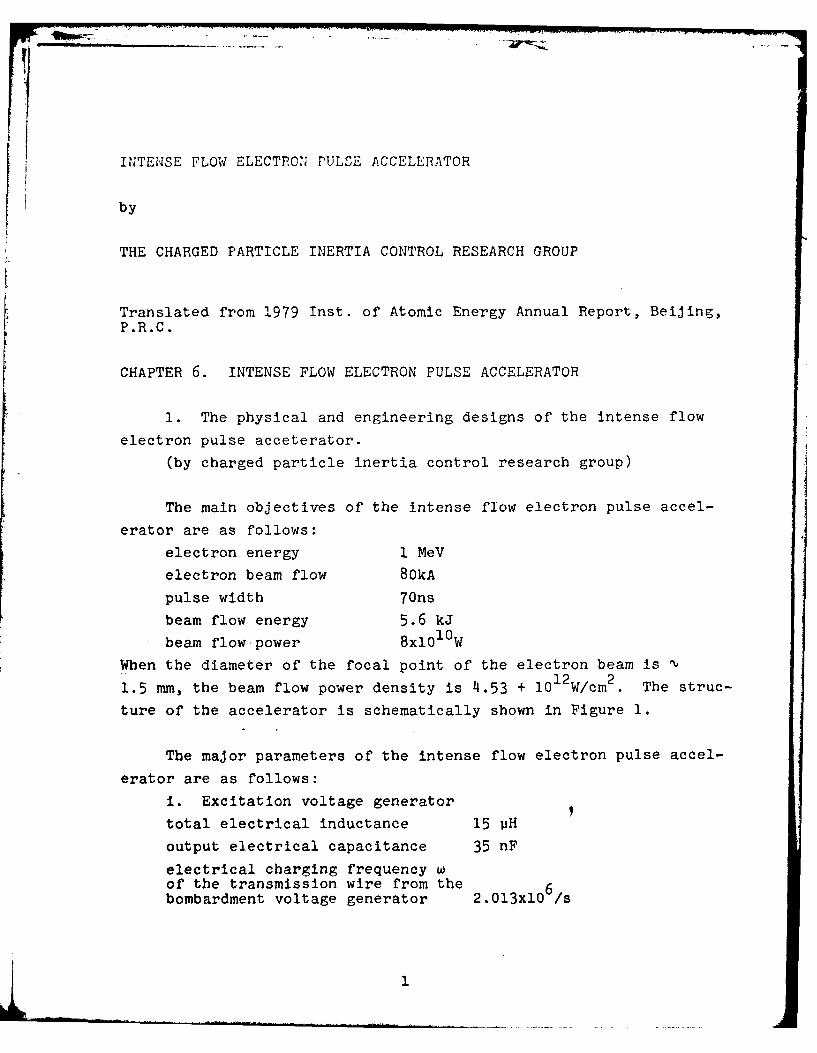
The main objectives of the intense flow electron pulse accel-
erator are as follows:
electron energy I MeV
electron beam flow 8OkA
pulse width 7Ons
beam flow energy 5.6 kJ
beam flow-power 8xl0 1 0W
When the diameter of the focal point of the electron beam is12 2
1.5 mm, the beam flow power density is 4.53 + 10 W/cm 2. The struc-
ture of the accelerator is schematically shown in Figure 1.
The major parameters of the intense flow electron pulse accel-
erator are as follows:
i. Excitation voltage generator
total electrical inductance 15 vH
output electrical capacitance 35 nF
electrical charging frequency wof the transmission wire from the 6bombardment voltage generator 2.013x10 /s
L1
ii. Water-medium double-layer coaxial transmission wire:
maximum charging voltage 1.12 MV and 1.21 MV
internal wire resistance 4.217 Q
external wire resistance 2.17 Q
transition section resistance 6.474 n
internal wire capacitance 8.48 nF
external wire capacitance 22.6 nF
electrical length of transmission wire 70 ns
outer diameter of inner cylinder(diameter) 48 cm
inside diameter of the middlecylinder 90 cm
outside diameter of the middlecylinder 91 cm
inside diameter of the outercylinder 126 cm
iii. Main switchdistance between electrodes \2 cm
maximum electrical field in themain switch 0.54 MV/cm
inductance of the main switch "14.9 nH
iv. The diode
diode resistance -v6 adiode capacitance "32.9 nF
diode inductance P35.5 nF
electron beam rising time "'25 ns
2
IM
i~1 ........ \u a 4ill
I oi,.oI,
7wo]
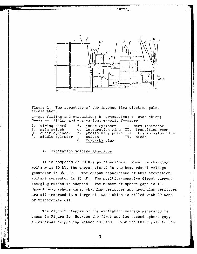
Figure 1. The structure of the intense flow electron pulseaccelerator.
a--gas filling and evacuation; b--evacuation; c--evacuation;
d--water filling and evacuation; e--oil; f--water
1. wiring board 5. inner cylinder I. Marx generator2. main switch 6. integration ring II. transition room3. outer cylinder 7. preliminary pulse III. transmission line4. middle cylinder switch IV. diode
8. Zokovsky ring
A. Excitation voltage generator
It is composed of 20 0.7 pF capacitors. When the charging
voltage is 70 kV, the energy stored in the bombardment voltage
generator is 34.3 kJ. The output capacitance of this excitation
voltage generator is 35 nF. The positive-negative direct current
charging method is adopted. The number of sphere gaps is 10.
Capacitors, sphere gaps, charging resistors and grounding resistors
are all immersed in a large oil tank which is filled with 30 tons
of transformer oil.
The circuit diagram of the excitation voltage generator is
shown in Figure 2. Between the first and the second sphere gap,
an external triggering method is used. From the third pair to the
!3

tenth pair of sphere gaps, it relies on the penetrating voltage
to sequentially break them through.
The total in uctance of the excitation voltage generator
is 14.3 pH which includes the inductance of the connecting wire
8.83 UH. The charging time of the excitation voltage generator
with respect to the transmission line is about 0.9 us. It is
advisable to minimize the electrical inductance of the excitation
voltage generator in order to reduce the charging time for the
transmission wire, to increase the pressure resistance capability
of the transmission wire and to reduce the energy loss from the
water medium of the transmission line (the time constant of leak-
age through the water medium is 7 ps). Improving the quality of
the pulsing capacitors, reducing the volume and to minimize the
inductance of the connecting wire are the important ways to reduce
the inductance of the excitation voltage generator. A resistance
network simulation method was used to calculate the values of break
through voltage for each sphere gap.
B. Water-medium double-layer coaxial tranmission wire
Using the excitation voltage generator to charge the double-
layer coaxial transmission line by harmonic oscillation charging,
the efficiency of energy transmission can be raised. In the physi-
cal design of the accelerator, a computer is used to obtain the
numerical so.lutions using the Laplace transformation method and
the state equation method respectively for the accurate determina-
tion of the voltage transmission efficiency as well as the energy
transmission efficiency.
As for the consideration of the insulating voltage endurance
and the geometric dimension of the transmission line, it primarily
follows the electrical break through equation in the water medium
[lJ.to select the diameters of the inner, middle and outer cylin-
ders in the transmission line in order to ensure that the actual
4
-I. It
It Ja ic c{ oif 10 _taes
___C C D.It i
Figure 2. Basic principle schematic diagram of theexcitation voltage generator
field strength at any point inside the transmission line is less
than the allowed field strength plus a sufficient safety coeffi-
cient (see the K value in Table 2). We have carried out as opti-
mal parametric calculation using the computer with regard to the
requirements of the combined voltage endurance, voltage trans-
mission and energy transmission.
The major field strength parameters in the design of the
transmission line are listed in the table below. The field
strength of the transmission line is calculated using a network
method by a TQ-6 electronic computer. The emphasis was especially
placed on the study of the distribution of electric field near the
end of the middle cylinder and the beginning of the outer cylinder.
Furthermore, special arrangement was made to modif'y the shape of
the end of the middle cylinder and the head of the outer cylinder
to raise the voltage endurance of the transmission wire.
The cylinder support material in the transmission line is
the gold red stone ceramic. Its dielectric constant E = 75-80.
5
It was experimentally obtained that its voltafe e:ndurance in
water is 12 kV/mm with respect to a cross wave pulse with a
rising time of 2 lis. Because its dielectric constant is very
close-to that of water (81), the effect of the support material
on the propagation of electromagnetic wave in water can be
minimized.
Under the short pulse high voltage condition, water is a rela-
tively ideal transmitting medium. Deionization process must be
carried out to ensure that the resistivity of water is larger
than 1 MS1 cm. The deionization system provides 0.5 tons of water
per hour. In order to prevent bubble formation due to air orig-
inally in the transmission wire during the injection process of
water into the transmission wire which makes the electrical break
through much easier, gas evacuation procedure was adopted before
water injection into the transmission wire.
C. Sphere gap and main switch
The material of the spark sphere gap outer cylinder is nylon
6. The outer diameter of the tube is 150 mm, inner diameter is
110 mm and length of the cylinder is 300 mm. The design of the
shape of the sphere gap electrode is mainly to assure that there
is a uniform electric field area at the center of the sphere gap.
For this the tips of both electrodes must have a plateau area.
The TQ-6 computer was used to compute the electric fields under
various conditions of the diameter of the plateau and the radius of
curvature from the plateau tip to the rear of the electrode. The
electrode material of the sphere gap tip is stainless steel or a
copper-tungsten alloy. The sphere gap is filled with 1-4 atmos-
pheric pressure of N2 or a gas mixture (90% N2 and 10% SF6 ).
At various electrode distances, the relation between break
through voltage and the gas pressure is plotted.
In orde~r to reduce the inductance of the main switch, it Is
filled with 10 atmospheric pressure of SF 6 gas to decrease the
electrode distance.
D. Diode
The designed resistance of the diode is 6 Q. Because the
resistance of the transmission line is 6.47 0, a 6Q resistance for
the diode is ideal from the energy transmission efficiency point
of view. Considering the self-constriction of the electron beam,
it requires a higher V/y ratio for better performance. The opti-
mal diode resistance may be lower than the matching resistance.
This can be obtained by changing the distance between the cathode
and the anode. The cathode of the diode was experimented using
several types of shape and structure . It included needle shaped
cathode , solid cone cathode , hollow cone cathode. , etc. The
materials used were tungsten, graphite, bronze and stainless steel.
The material and thickness of the anode will be determined by
future physical experiments. At this moment, the design adopted
the use of 2-6 mm thick aluminum plate for testing.
The diode used a radical insulation arrangement. An 8 cm
thick organic glass plate was used to separate the deionized water
and the vacuum zone. The outside diameter of the insulating
plate was selected to be 2.72 times that of its inner diameter.
The maximum value of field strength exerted on the inner diameter
of the insulating plate is 45 kV/cm. This is much lower than the
voltage endurance strength for organic glass reported in the lit-
erature. From the angle of voltage endurance, it is very reliaule.
In order to control the reaction of the pulse to the diode,
a section of organic glass is inserted in the conducting red of
the cathode. Its length can vary. Through the capacitive voltage
divider, the magnitude of the pulse can be adjusted. When the
main pulse reached the section inserted by the organic glass, it
7
2 MV 3 tm1 4 kV/cm 5 kY/cm "
G F4 1 4 i 0.09 17300 It.2 141.2 0.5168
7 I* N A -1.12 4BOM 42.7 2'7.Z 0.166
L, 3 U t ft -1.12 4h00 76 257.6 0.2L"
9 6 & 4 4 t 0 72400 S 125 0.44
10 4. a7*'3k 5330 108 314 0.344
11 P * h ± A F(Ifir.C.Marti ,-. f itt I.J.i'61 0.6" Is R 14
1--electric field parameter of Blumlein transmission line design;2--charging voltage; 3--electrode area; 4--experimental fieldstrength E; 5--allowable field strength F; 6--outside surfaceof outer cylinder; 7--inside surface of middle cylinder; 8--outside surface of middle cylinder; 9--inside surface of outercylinder; 10--end of the middle cylinder; 11--the allowablefield strength value F is obtained using J. C. Martin equationwithin an effective charging time teff 0.6 Vs.
is conducting through surface discharge.
The electric field distribution and electron trajectory
inside the diode have been calculated in the computer.
E. Physical measurement of the electron beam parameters
Resistance voltage divider and capacitance voltage divider
were designed to measure the high voltage pulse in the diode, in
transmission wireand at the output end of the excitation voltage
generator. In the meantime, design and modification were made to
use Zokovsky coil, integration ring and current divider to measure
the current in the diode and the return current.
Prototype experimental apparatus to measure current and volt-
age as described above which can be used on small transmission
lines has been designed.
The various parts of the accelerator are in the process of
being fabricated.
8

(written by Wang Nie Yen)
REFERENCES
(I] J.D.ShipmAu, IEEE Transactioa on nuclear science. NS-16. No.4, p.243.E2) K.R.Prestvwicb and D.L.Jobason, IEEE Transaction on nuclear science, NS-16, No.5. P.64.
2. The calculation of electrical field of Blumlein
transmission line
Kung Fong, Yang Da Wei, Wang Shu Moa and Wang Nie Yen
The basic method used in the calculation of electric field
is the square network super relax iteration method. Using the
difference equation format in the Laplace equation in the axial
symmetric cylindrical coordinate system, the solution is obtained
using iteration at the network matrix point. The iteration was
realized in a 129x 561 matrix. A method similar to the one used
by J. E. Boers Eli was used to treat the difference equation on
the interface of different media. We also deduced the difference
equations at different intersecting points at the interface.
Using the program compiled with BCY language, the calculation
was carried out on a TQ-6 computer. The program can directly out-
put the coordinates of equi-potential lines. The equl-potential
value is determined in steps of 5% of the potential between thetwo electrodes. The program also has the capability to directly
use the wide outputer printer to plot the distribution of equi-
potential lines. It is also capable of magnifying the portion
of area in the equi-potential distribution diagram which is of
interest.
I9
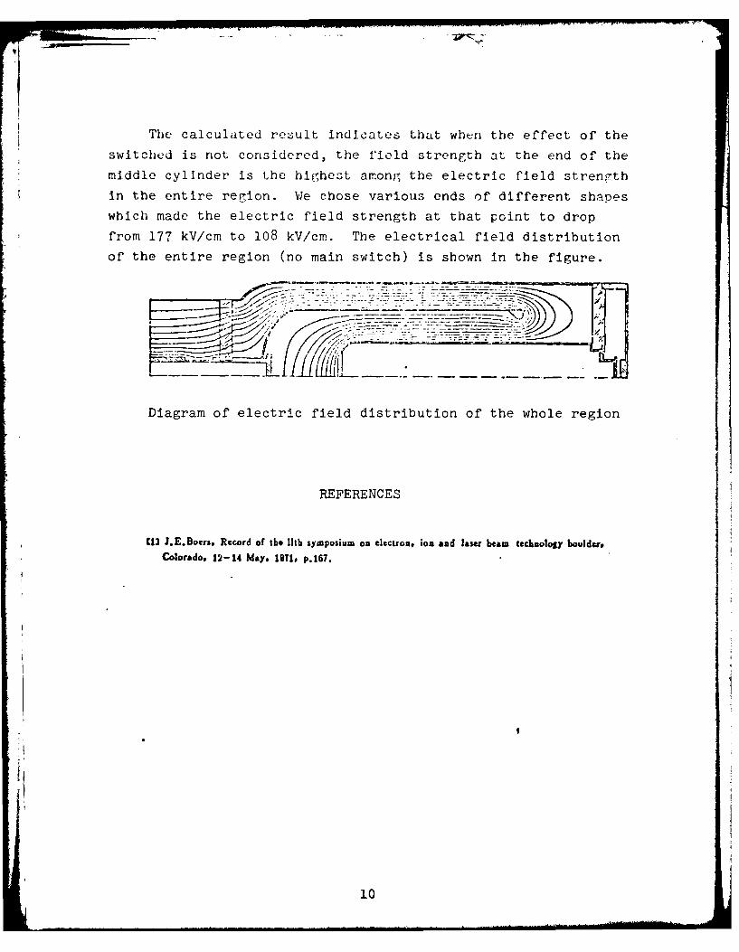
The calculated result indicates that when the effect of the
switched is not considered, the field strength at the end of the
middle cylinder is the highest among the electric field streng.th
in the entire region. We chose various ends of different shapes
which made the electric field strength at that point to drop
from 177 kV/cm to 108 kV/cm. The electrical field distribution
of the entire region (no main switch) is shown In the figure.
Diagram of electric field distribution of the whole region
REFERENCES
1] J.E.Boers. Record of the lth symposium on electron, ion and laser besm technology boulder,Colorado. 12-14 May, 1971. p.167.
10

I